EP4175020A1 - Battery module and battery pack including same - Google Patents
Battery module and battery pack including same Download PDFInfo
- Publication number
- EP4175020A1 EP4175020A1 EP22786739.7A EP22786739A EP4175020A1 EP 4175020 A1 EP4175020 A1 EP 4175020A1 EP 22786739 A EP22786739 A EP 22786739A EP 4175020 A1 EP4175020 A1 EP 4175020A1
- Authority
- EP
- European Patent Office
- Prior art keywords
- lower plate
- bottom part
- battery module
- battery
- module
- Prior art date
- Legal status (The legal status is an assumption and is not a legal conclusion. Google has not performed a legal analysis and makes no representation as to the accuracy of the status listed.)
- Pending
Links
- 239000003507 refrigerant Substances 0.000 claims abstract description 19
- 229910052751 metal Inorganic materials 0.000 claims abstract description 15
- 239000002184 metal Substances 0.000 claims abstract description 15
- 150000002739 metals Chemical class 0.000 claims abstract description 4
- 239000000463 material Substances 0.000 claims description 93
- 229910000838 Al alloy Inorganic materials 0.000 claims description 11
- 229910052782 aluminium Inorganic materials 0.000 claims description 11
- 238000005304 joining Methods 0.000 claims description 11
- 229910052802 copper Inorganic materials 0.000 claims description 10
- 229910052749 magnesium Inorganic materials 0.000 claims description 10
- 229910052748 manganese Inorganic materials 0.000 claims description 10
- 238000002844 melting Methods 0.000 claims description 9
- 230000008018 melting Effects 0.000 claims description 9
- XAGFODPZIPBFFR-UHFFFAOYSA-N aluminium Chemical compound [Al] XAGFODPZIPBFFR-UHFFFAOYSA-N 0.000 claims description 8
- 230000004907 flux Effects 0.000 claims description 7
- 229910052710 silicon Inorganic materials 0.000 claims description 6
- 229910052792 caesium Inorganic materials 0.000 claims description 4
- TVFDJXOCXUVLDH-UHFFFAOYSA-N caesium atom Chemical compound [Cs] TVFDJXOCXUVLDH-UHFFFAOYSA-N 0.000 claims description 4
- 238000004806 packaging method and process Methods 0.000 claims description 2
- 238000001816 cooling Methods 0.000 description 21
- 238000003466 welding Methods 0.000 description 14
- 239000011347 resin Substances 0.000 description 13
- 229920005989 resin Polymers 0.000 description 13
- 239000007769 metal material Substances 0.000 description 11
- 238000005520 cutting process Methods 0.000 description 10
- 238000000034 method Methods 0.000 description 8
- WHXSMMKQMYFTQS-UHFFFAOYSA-N Lithium Chemical compound [Li] WHXSMMKQMYFTQS-UHFFFAOYSA-N 0.000 description 6
- 229910052744 lithium Inorganic materials 0.000 description 6
- 239000000956 alloy Substances 0.000 description 5
- 230000008569 process Effects 0.000 description 5
- PXHVJJICTQNCMI-UHFFFAOYSA-N Nickel Chemical compound [Ni] PXHVJJICTQNCMI-UHFFFAOYSA-N 0.000 description 4
- 230000000694 effects Effects 0.000 description 4
- 230000004048 modification Effects 0.000 description 4
- 238000012986 modification Methods 0.000 description 4
- 230000008901 benefit Effects 0.000 description 3
- 238000005219 brazing Methods 0.000 description 3
- 230000008859 change Effects 0.000 description 2
- 230000006866 deterioration Effects 0.000 description 2
- 238000004880 explosion Methods 0.000 description 2
- 230000017525 heat dissipation Effects 0.000 description 2
- 238000004519 manufacturing process Methods 0.000 description 2
- 239000007773 negative electrode material Substances 0.000 description 2
- 229910052759 nickel Inorganic materials 0.000 description 2
- 239000007774 positive electrode material Substances 0.000 description 2
- 238000007789 sealing Methods 0.000 description 2
- JOYRKODLDBILNP-UHFFFAOYSA-N Ethyl urethane Chemical compound CCOC(N)=O JOYRKODLDBILNP-UHFFFAOYSA-N 0.000 description 1
- UFHFLCQGNIYNRP-UHFFFAOYSA-N Hydrogen Chemical compound [H][H] UFHFLCQGNIYNRP-UHFFFAOYSA-N 0.000 description 1
- NIXOWILDQLNWCW-UHFFFAOYSA-N acrylic acid group Chemical group C(C=C)(=O)O NIXOWILDQLNWCW-UHFFFAOYSA-N 0.000 description 1
- 239000000853 adhesive Substances 0.000 description 1
- 230000001070 adhesive effect Effects 0.000 description 1
- 238000003915 air pollution Methods 0.000 description 1
- 229910045601 alloy Inorganic materials 0.000 description 1
- OJIJEKBXJYRIBZ-UHFFFAOYSA-N cadmium nickel Chemical compound [Ni].[Cd] OJIJEKBXJYRIBZ-UHFFFAOYSA-N 0.000 description 1
- 239000003575 carbonaceous material Substances 0.000 description 1
- 239000000498 cooling water Substances 0.000 description 1
- 238000007599 discharging Methods 0.000 description 1
- 238000010292 electrical insulation Methods 0.000 description 1
- 239000008151 electrolyte solution Substances 0.000 description 1
- 238000005516 engineering process Methods 0.000 description 1
- 230000001747 exhibiting effect Effects 0.000 description 1
- 238000001125 extrusion Methods 0.000 description 1
- 239000002803 fossil fuel Substances 0.000 description 1
- 230000005484 gravity Effects 0.000 description 1
- 229910052739 hydrogen Inorganic materials 0.000 description 1
- 239000001257 hydrogen Substances 0.000 description 1
- 239000007788 liquid Substances 0.000 description 1
- 230000003446 memory effect Effects 0.000 description 1
- QELJHCBNGDEXLD-UHFFFAOYSA-N nickel zinc Chemical compound [Ni].[Zn] QELJHCBNGDEXLD-UHFFFAOYSA-N 0.000 description 1
- 230000001151 other effect Effects 0.000 description 1
- 229920001296 polysiloxane Polymers 0.000 description 1
- 230000003014 reinforcing effect Effects 0.000 description 1
- 239000000243 solution Substances 0.000 description 1
- 239000000126 substance Substances 0.000 description 1
Images


Classifications
-
- H—ELECTRICITY
- H01—ELECTRIC ELEMENTS
- H01M—PROCESSES OR MEANS, e.g. BATTERIES, FOR THE DIRECT CONVERSION OF CHEMICAL ENERGY INTO ELECTRICAL ENERGY
- H01M10/00—Secondary cells; Manufacture thereof
- H01M10/60—Heating or cooling; Temperature control
- H01M10/65—Means for temperature control structurally associated with the cells
- H01M10/655—Solid structures for heat exchange or heat conduction
- H01M10/6551—Surfaces specially adapted for heat dissipation or radiation, e.g. fins or coatings
-
- H—ELECTRICITY
- H01—ELECTRIC ELEMENTS
- H01M—PROCESSES OR MEANS, e.g. BATTERIES, FOR THE DIRECT CONVERSION OF CHEMICAL ENERGY INTO ELECTRICAL ENERGY
- H01M50/00—Constructional details or processes of manufacture of the non-active parts of electrochemical cells other than fuel cells, e.g. hybrid cells
- H01M50/20—Mountings; Secondary casings or frames; Racks, modules or packs; Suspension devices; Shock absorbers; Transport or carrying devices; Holders
- H01M50/218—Mountings; Secondary casings or frames; Racks, modules or packs; Suspension devices; Shock absorbers; Transport or carrying devices; Holders characterised by the material
- H01M50/22—Mountings; Secondary casings or frames; Racks, modules or packs; Suspension devices; Shock absorbers; Transport or carrying devices; Holders characterised by the material of the casings or racks
- H01M50/222—Inorganic material
- H01M50/224—Metals
-
- B—PERFORMING OPERATIONS; TRANSPORTING
- B23—MACHINE TOOLS; METAL-WORKING NOT OTHERWISE PROVIDED FOR
- B23K—SOLDERING OR UNSOLDERING; WELDING; CLADDING OR PLATING BY SOLDERING OR WELDING; CUTTING BY APPLYING HEAT LOCALLY, e.g. FLAME CUTTING; WORKING BY LASER BEAM
- B23K1/00—Soldering, e.g. brazing, or unsoldering
- B23K1/0008—Soldering, e.g. brazing, or unsoldering specially adapted for particular articles or work
- B23K1/0012—Brazing heat exchangers
-
- B—PERFORMING OPERATIONS; TRANSPORTING
- B23—MACHINE TOOLS; METAL-WORKING NOT OTHERWISE PROVIDED FOR
- B23K—SOLDERING OR UNSOLDERING; WELDING; CLADDING OR PLATING BY SOLDERING OR WELDING; CUTTING BY APPLYING HEAT LOCALLY, e.g. FLAME CUTTING; WORKING BY LASER BEAM
- B23K1/00—Soldering, e.g. brazing, or unsoldering
- B23K1/0008—Soldering, e.g. brazing, or unsoldering specially adapted for particular articles or work
- B23K1/0016—Brazing of electronic components
-
- B—PERFORMING OPERATIONS; TRANSPORTING
- B23—MACHINE TOOLS; METAL-WORKING NOT OTHERWISE PROVIDED FOR
- B23K—SOLDERING OR UNSOLDERING; WELDING; CLADDING OR PLATING BY SOLDERING OR WELDING; CUTTING BY APPLYING HEAT LOCALLY, e.g. FLAME CUTTING; WORKING BY LASER BEAM
- B23K1/00—Soldering, e.g. brazing, or unsoldering
- B23K1/19—Soldering, e.g. brazing, or unsoldering taking account of the properties of the materials to be soldered
-
- B—PERFORMING OPERATIONS; TRANSPORTING
- B23—MACHINE TOOLS; METAL-WORKING NOT OTHERWISE PROVIDED FOR
- B23K—SOLDERING OR UNSOLDERING; WELDING; CLADDING OR PLATING BY SOLDERING OR WELDING; CUTTING BY APPLYING HEAT LOCALLY, e.g. FLAME CUTTING; WORKING BY LASER BEAM
- B23K35/00—Rods, electrodes, materials, or media, for use in soldering, welding, or cutting
- B23K35/22—Rods, electrodes, materials, or media, for use in soldering, welding, or cutting characterised by the composition or nature of the material
- B23K35/36—Selection of non-metallic compositions, e.g. coatings, fluxes; Selection of soldering or welding materials, conjoint with selection of non-metallic compositions, both selections being of interest
- B23K35/362—Selection of compositions of fluxes
-
- H—ELECTRICITY
- H01—ELECTRIC ELEMENTS
- H01M—PROCESSES OR MEANS, e.g. BATTERIES, FOR THE DIRECT CONVERSION OF CHEMICAL ENERGY INTO ELECTRICAL ENERGY
- H01M10/00—Secondary cells; Manufacture thereof
- H01M10/60—Heating or cooling; Temperature control
- H01M10/64—Heating or cooling; Temperature control characterised by the shape of the cells
- H01M10/647—Prismatic or flat cells, e.g. pouch cells
-
- H—ELECTRICITY
- H01—ELECTRIC ELEMENTS
- H01M—PROCESSES OR MEANS, e.g. BATTERIES, FOR THE DIRECT CONVERSION OF CHEMICAL ENERGY INTO ELECTRICAL ENERGY
- H01M10/00—Secondary cells; Manufacture thereof
- H01M10/60—Heating or cooling; Temperature control
- H01M10/65—Means for temperature control structurally associated with the cells
- H01M10/653—Means for temperature control structurally associated with the cells characterised by electrically insulating or thermally conductive materials
-
- H—ELECTRICITY
- H01—ELECTRIC ELEMENTS
- H01M—PROCESSES OR MEANS, e.g. BATTERIES, FOR THE DIRECT CONVERSION OF CHEMICAL ENERGY INTO ELECTRICAL ENERGY
- H01M10/00—Secondary cells; Manufacture thereof
- H01M10/60—Heating or cooling; Temperature control
- H01M10/65—Means for temperature control structurally associated with the cells
- H01M10/655—Solid structures for heat exchange or heat conduction
- H01M10/6554—Rods or plates
- H01M10/6555—Rods or plates arranged between the cells
-
- H—ELECTRICITY
- H01—ELECTRIC ELEMENTS
- H01M—PROCESSES OR MEANS, e.g. BATTERIES, FOR THE DIRECT CONVERSION OF CHEMICAL ENERGY INTO ELECTRICAL ENERGY
- H01M10/00—Secondary cells; Manufacture thereof
- H01M10/60—Heating or cooling; Temperature control
- H01M10/65—Means for temperature control structurally associated with the cells
- H01M10/655—Solid structures for heat exchange or heat conduction
- H01M10/6556—Solid parts with flow channel passages or pipes for heat exchange
-
- H—ELECTRICITY
- H01—ELECTRIC ELEMENTS
- H01M—PROCESSES OR MEANS, e.g. BATTERIES, FOR THE DIRECT CONVERSION OF CHEMICAL ENERGY INTO ELECTRICAL ENERGY
- H01M50/00—Constructional details or processes of manufacture of the non-active parts of electrochemical cells other than fuel cells, e.g. hybrid cells
- H01M50/20—Mountings; Secondary casings or frames; Racks, modules or packs; Suspension devices; Shock absorbers; Transport or carrying devices; Holders
- H01M50/218—Mountings; Secondary casings or frames; Racks, modules or packs; Suspension devices; Shock absorbers; Transport or carrying devices; Holders characterised by the material
- H01M50/22—Mountings; Secondary casings or frames; Racks, modules or packs; Suspension devices; Shock absorbers; Transport or carrying devices; Holders characterised by the material of the casings or racks
- H01M50/231—Mountings; Secondary casings or frames; Racks, modules or packs; Suspension devices; Shock absorbers; Transport or carrying devices; Holders characterised by the material of the casings or racks having a layered structure
-
- B—PERFORMING OPERATIONS; TRANSPORTING
- B23—MACHINE TOOLS; METAL-WORKING NOT OTHERWISE PROVIDED FOR
- B23K—SOLDERING OR UNSOLDERING; WELDING; CLADDING OR PLATING BY SOLDERING OR WELDING; CUTTING BY APPLYING HEAT LOCALLY, e.g. FLAME CUTTING; WORKING BY LASER BEAM
- B23K2101/00—Articles made by soldering, welding or cutting
- B23K2101/04—Tubular or hollow articles
- B23K2101/14—Heat exchangers
-
- B—PERFORMING OPERATIONS; TRANSPORTING
- B23—MACHINE TOOLS; METAL-WORKING NOT OTHERWISE PROVIDED FOR
- B23K—SOLDERING OR UNSOLDERING; WELDING; CLADDING OR PLATING BY SOLDERING OR WELDING; CUTTING BY APPLYING HEAT LOCALLY, e.g. FLAME CUTTING; WORKING BY LASER BEAM
- B23K2101/00—Articles made by soldering, welding or cutting
- B23K2101/36—Electric or electronic devices
-
- H—ELECTRICITY
- H01—ELECTRIC ELEMENTS
- H01M—PROCESSES OR MEANS, e.g. BATTERIES, FOR THE DIRECT CONVERSION OF CHEMICAL ENERGY INTO ELECTRICAL ENERGY
- H01M10/00—Secondary cells; Manufacture thereof
- H01M10/60—Heating or cooling; Temperature control
- H01M10/61—Types of temperature control
- H01M10/613—Cooling or keeping cold
-
- H—ELECTRICITY
- H01—ELECTRIC ELEMENTS
- H01M—PROCESSES OR MEANS, e.g. BATTERIES, FOR THE DIRECT CONVERSION OF CHEMICAL ENERGY INTO ELECTRICAL ENERGY
- H01M10/00—Secondary cells; Manufacture thereof
- H01M10/60—Heating or cooling; Temperature control
- H01M10/62—Heating or cooling; Temperature control specially adapted for specific applications
- H01M10/625—Vehicles
-
- H—ELECTRICITY
- H01—ELECTRIC ELEMENTS
- H01M—PROCESSES OR MEANS, e.g. BATTERIES, FOR THE DIRECT CONVERSION OF CHEMICAL ENERGY INTO ELECTRICAL ENERGY
- H01M2220/00—Batteries for particular applications
- H01M2220/20—Batteries in motive systems, e.g. vehicle, ship, plane
-
- H—ELECTRICITY
- H01—ELECTRIC ELEMENTS
- H01M—PROCESSES OR MEANS, e.g. BATTERIES, FOR THE DIRECT CONVERSION OF CHEMICAL ENERGY INTO ELECTRICAL ENERGY
- H01M50/00—Constructional details or processes of manufacture of the non-active parts of electrochemical cells other than fuel cells, e.g. hybrid cells
- H01M50/20—Mountings; Secondary casings or frames; Racks, modules or packs; Suspension devices; Shock absorbers; Transport or carrying devices; Holders
- H01M50/204—Racks, modules or packs for multiple batteries or multiple cells
- H01M50/207—Racks, modules or packs for multiple batteries or multiple cells characterised by their shape
- H01M50/209—Racks, modules or packs for multiple batteries or multiple cells characterised by their shape adapted for prismatic or rectangular cells
-
- H—ELECTRICITY
- H01—ELECTRIC ELEMENTS
- H01M—PROCESSES OR MEANS, e.g. BATTERIES, FOR THE DIRECT CONVERSION OF CHEMICAL ENERGY INTO ELECTRICAL ENERGY
- H01M50/00—Constructional details or processes of manufacture of the non-active parts of electrochemical cells other than fuel cells, e.g. hybrid cells
- H01M50/20—Mountings; Secondary casings or frames; Racks, modules or packs; Suspension devices; Shock absorbers; Transport or carrying devices; Holders
- H01M50/204—Racks, modules or packs for multiple batteries or multiple cells
- H01M50/207—Racks, modules or packs for multiple batteries or multiple cells characterised by their shape
- H01M50/211—Racks, modules or packs for multiple batteries or multiple cells characterised by their shape adapted for pouch cells
-
- H—ELECTRICITY
- H01—ELECTRIC ELEMENTS
- H01M—PROCESSES OR MEANS, e.g. BATTERIES, FOR THE DIRECT CONVERSION OF CHEMICAL ENERGY INTO ELECTRICAL ENERGY
- H01M50/00—Constructional details or processes of manufacture of the non-active parts of electrochemical cells other than fuel cells, e.g. hybrid cells
- H01M50/20—Mountings; Secondary casings or frames; Racks, modules or packs; Suspension devices; Shock absorbers; Transport or carrying devices; Holders
- H01M50/249—Mountings; Secondary casings or frames; Racks, modules or packs; Suspension devices; Shock absorbers; Transport or carrying devices; Holders specially adapted for aircraft or vehicles, e.g. cars or trains
-
- Y—GENERAL TAGGING OF NEW TECHNOLOGICAL DEVELOPMENTS; GENERAL TAGGING OF CROSS-SECTIONAL TECHNOLOGIES SPANNING OVER SEVERAL SECTIONS OF THE IPC; TECHNICAL SUBJECTS COVERED BY FORMER USPC CROSS-REFERENCE ART COLLECTIONS [XRACs] AND DIGESTS
- Y02—TECHNOLOGIES OR APPLICATIONS FOR MITIGATION OR ADAPTATION AGAINST CLIMATE CHANGE
- Y02E—REDUCTION OF GREENHOUSE GAS [GHG] EMISSIONS, RELATED TO ENERGY GENERATION, TRANSMISSION OR DISTRIBUTION
- Y02E60/00—Enabling technologies; Technologies with a potential or indirect contribution to GHG emissions mitigation
- Y02E60/10—Energy storage using batteries
Definitions
- the present disclosure relates to a battery module and a battery pack including the same, and more particularly, to a heat sink that is integrated with the module frame and is formed of the module frame and dissimilar metals.
- chargeable/dischargeable secondary batteries are used as a power source for an electric vehicle (EV), a hybrid electric vehicle (HEV), a plug-in hybrid electric vehicle (P-HEV) and the like, in an attempt to solve air pollution and the like caused by existing gasoline vehicles using fossil fuel. Therefore, there is a growing need for development of the secondary battery.
- EV electric vehicle
- HEV hybrid electric vehicle
- P-HEV plug-in hybrid electric vehicle
- commercialized secondary batteries include a nickel cadmium battery, a nickel hydrogen battery, a nickel zinc battery, and a lithium secondary battery.
- the lithium secondary battery has come into the spotlight because they have advantages, for example, hardly exhibiting memory effects compared to nickel-based secondary batteries and thus being freely charged and discharged, and having very low self-discharge rate and high energy density.
- Such lithium secondary battery mainly uses a lithium-based oxide and a carbonaceous material as a positive electrode active material and a negative electrode active material, respectively.
- the lithium secondary battery includes an electrode assembly in which a positive electrode plate and a negative electrode plate, each being coated with the positive electrode active material and the negative electrode active material, are arranged with a separator being interposed between them, and a battery case which seals and houses the electrode assembly together with an electrolyte solution.
- the lithium secondary battery may be classified based on the shape of the exterior material into a can type secondary battery in which the electrode assembly is mounted in a metal can, and a pouch-type secondary battery in which the electrode assembly is mounted in a pouch of an aluminum laminate sheet.
- a battery module in which a large number of battery cells are electrically connected is used.
- a large number of battery cells are connected to each other in series or parallel to form a cell assembly, thereby improving capacity and output.
- one or more battery modules can be mounted together with various control and protection systems such as a BMS (battery management system) and a cooling system to form a battery pack.
- BMS battery management system
- a large number of secondary batteries that is, a battery module or a battery pack having battery cells, can add up the heat generated from the large number of battery cells in a narrow space, so that the temperature can rise more quickly and excessively.
- a battery module in which a large number of battery cells are stacked, and a battery pack equipped with such a battery module can obtain high output, but it is not easy to remove heat generated from the battery cells during charging and discharging.
- a battery module included in a vehicle battery pack it is frequently exposed to direct sunlight and may be placed under high-temperature conditions such as summer or desert areas.
- Fig. 1 is a perspective view which shows a conventional battery module.
- Fig. 2 is a cross-section taken along the cutting line A-A' of Fig. 1 .
- the conventional battery module 10 is configured such that a plurality of battery cells 11 are stacked to form a battery cell stack 20, and the battery cell stack 20 is housed in the module frame 30.
- the battery module 10 since the battery module 10 includes a plurality of battery cells 11, it generates a large amount of heat in a charge and discharge process.
- the battery module 10 may include a thermal conductive resin layer 40 located between the battery cell stack 20 and the bottom part 31 of the module frame 30.
- the battery module 10 since the battery module 10 includes a plurality of battery cells 11, it generates a large amount of heat in a charge and discharge process.
- the battery module 10 may include a thermal conductive resin layer 40 located between the battery cell stack 20 and the bottom part 31 of the module frame 30. Further, when the battery module 10 is mounted on the pack frame to form a battery pack, a heat transfer member 50 and a heat sink 60 may be sequentially located below the battery module 10.
- the heat transfer member 50 may be a heat dissipation pad, and the heat sink 60 may have a refrigerant flow path formed therein.
- Fig. 3 is an enlarged view of a region A1 of Fig. 2 .
- the heat generated from the battery cell 11 sequentially passes through a thermal conductive resin layer 40, a bottom part 31 of a module frame 30, a heat transfer member 50, and a heat sink 60 along the direction toward the heat sink 60 to be transferred to the outside of the battery module 10.
- the heat transfer path is complicated as described above, which makes it difficult to effectively transfer the heat generated from the battery cell 11 to the outside.
- the module frame 30 itself may deteriorate the heat conduction characteristics, and a fine air layer such as an air gap that can be formed between each of the module frame 30, the heat transfer member 50 and the heat sink 60 may also deteriorate the heat conduction characteristics.
- a battery module comprising: a battery cell stack in which a plurality of battery cells are stacked; a module frame for housing the battery cell stack; and a heat sink located at the bottom part of the module frame, wherein the heat sink comprises an upper plate and a lower plate, wherein the upper plate of the heat sink constitutes a bottom part of the module frame, wherein a refrigerant flow path is formed between the bottom part and the lower plate, and wherein the bottom part and the lower plate are formed of dissimilar metals from each other.
- the bottom part and the lower plate may be formed of aluminum materials which are dissimilar from each other.
- the bottom part may include a first material containing Mg
- the lower plate may include a second material containing Si and a third material containing Mn.
- the first material may be an aluminum alloy containing Mg, Si, Cu and Mn.
- the second material may be an aluminum alloy containing Si.
- the third material may be an aluminum alloy containing Mn, Mg and Cu.
- the first material may be an aluminum alloy containing Mg, Si, Cu and Mn
- the third material may be an aluminum alloy containing Mn, Mg and Cu, and a content of Mg contained in the first material may be larger than a content of Mg contained in the third material.
- the lower plate has a structure in which two layers are stacked and may include a first lower plate and a second lower plate.
- the first lower plate has a structure stacked on the second lower plate, wherein one surface of the first lower plate may be located opposite to the bottom part, and one surface of the second lower plate may be located while making contact with the other surface of the first lower plate.
- the bottom part may include a first material containing Mg
- the first lower plate may include a second material containing Si
- the second lower plate may include a third material containing Mn.
- the bottom part may further include an auxiliary layer which is located between a layer formed of a first material containing Mg and the lower plates.
- the auxiliary layer may be formed of a third material containing Mn.
- the bottom part and the lower plate may be joined by melting a metal located between the bottom part and the lower plate.
- the battery module may further include a clad layer located between the bottom part and the lower plate.
- the clad layer may have a lower melting point than the materials constituting the bottom part and the lower plate.
- the clad layer may include aluminum.
- the bottom part includes a first material containing Mg
- the lower plate includes a first lower plate including a second material containing Si and a second lower plate comprising a third material containing Mn
- the first lower plate may be stacked and located on the second lower plate.
- the flux used for joining the bottom part and the lower plate may include cesium (Cs).
- a battery pack comprising the above-mentioned at least one battery module, and a pack case for packaging the at least one battery module.
- the heat sink is integrated with the module frame, thereby capable of improving the cooling performance of the formed battery module and the battery pack including the same, increasing the rate of space utilization and reducing the manufacturing cost.
- the bottom part of the module frame constituting the heat sink and the lower plate joined thereto are formed of different types of metal series, thereby improving the cooling performance .
- planar when referred to as “planar”, it means when a target portion is viewed from the upper side, and when referred to as “cross-sectional”, it means when a target portion is viewed from the side of a cross section cut vertically.
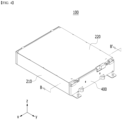
- Fig. 4 is a perspective view which shows a battery module according to an embodiment of the present disclosure.
- Fig. 5 is an exploded perspective view of the battery module of Fig. 4 .
- Fig. 6 is a perspective view which shows a heat sink included in the battery module of Fig. 4 .
- Fig. 7 is a cross-sectional view which shows a part of a cross-section taken along the cutting line D-D' of Fig. 6 .
- the battery module 100 includes a battery cell stack 120 in which a plurality of battery cells 110 are stacked, a module frame 200 for housing the battery cell stack 120, and a heat sink 300 located below the bottom part 210a of the module frame 200.
- the bottom part 210a of the module frame 200 constitutes an upper plate of the heat sink 300, and the recessed part 340 of the heat sink 300 and the bottom part 210a form a refrigerant flow path.
- the specific structure of the heat sink 300 will be described later in detail with reference to Figs. 6 to 7 .
- the battery cells 110 may be preferably pouch-type battery cells.
- the pouch-type battery cells can be manufactured by housing the electrode assembly in a pouch case of a laminated sheet including a resin layer and a metal layer, and then heat-sealing a sealing part of the pouch case. At this time, the battery cell 110 may be formed in a rectangular sheet-like structure.
- Such battery cells 110 may be formed in plural numbers, and the plurality of battery cells 110 form a battery cell stack 120 stacked so as to be electrically connected to each other.
- a plurality of battery cells 110 may be stacked along a direction parallel to the x-axis.
- the module frame 200 for housing the battery cell stack 120 may include an upper cover 220 and a U-shaped frame 210.
- the U-shaped frame 210 may include a bottom part 210a and two side surface parts 211 extending upward from both ends of the bottom part 210a.
- the bottom part 210a may cover the lower surface (-z-axis direction) of the battery cell stack 120
- the side surface part 211 may cover both side surfaces (x-axis direction and -x-axis direction) of the battery cell stack 120.
- the upper cover 220 may be formed in a single plate-shaped structure that wraps the lower surface wrapped by the U-shaped frame 210 and the remaining upper surface (z-axis direction) excluding the both side surfaces.
- the upper cover 220 and the U-shaped frame 210 can be joined by welding or the like in a state in which the corresponding corner portions are in contact with each other, thereby forming a structure that covers the battery cell stack 120 vertically and horizontally.
- the battery cell stack 120 can be physically protected through the upper cover 220 and the U-shaped frame 210.
- the upper cover 220 and the U-shaped frame 210 may include a metal material having a predetermined strength.
- the module frame 200 may be a mono frame in the form of a metal plate in which the upper surface, the lower surface, and both side surfaces are integrated. That is, this is not a structure in which the U-shaped frame 210 and the upper cover 220 are coupled with each other, but a structure in which the upper surface, the lower surface, and both side surfaces are integrated by being manufactured by extrusion molding.
- the end plate 400 may be located on the opened first side (y-axis direction) and the second side (-y-side direction) of the module frame 200, so that it may be formed so as to cover the battery cell stack 120.
- the end plate 400 can physically protect the battery cell stack 120 and other electronic instruments from external impact.
- a busbar frame mounted with a busbar, an insulating cover for electrical insulation, and the like may be located between the battery cell stack 120 and the end plate 400.
- the bottom part 210a of the module frame 200 constitutes the upper plate of the heat sink 300, and the recessed part 340 of the heat sink 300 and the bottom part 210a of the module frame 200 can form a refrigerant flow path C.
- the heat sink 300 may be formed at the lower part of the module frame 200.
- the heat sink 300 may be formed while making contact with the bottom part 210a of the module frame 200.
- the heat sink 300 includes a lower plate 310 that forms a skeleton of the heat sink 300 and is joined to the bottom part 210a of the module frame 200 and a recessed part 340 that is a path through which refrigerant flows.
- the bottom part 210a of the module frame 200 is not particularly limited, but may include a metal material.
- the bottom part 210a may include a first material including a metal material.
- the first material may include a material having high rigidity.
- the first material may include a material having a high Mg content.
- the first material may be an alloy material containing Al, Mg, Si, Cu, and Mn.
- the first material may include an Al60-based material. That is, the bottom part 210a may include the first material for strength of the battery module.
- the bottom part 210a of the module frame 200 is composed of an upper plate of the heat sink 300, and the bottom part 210a comes into direct contact with the refrigerant. Therefore, there is an advantage that more direct cooling by the refrigerant is possible.
- the heat sink 300 is integrated with the bottom part 210a of the module frame 200, the space utilization rate on the battery module 100 and the battery pack on which the battery module 100 is mounted can be further improved. This can be distinguished from the conventional case in which as shown in Figs. 2 and 3 , the upper configuration of the heat transfer member 50 and the heat sink 60 is located between the bottom part 31 and the refrigerant to indirectly cool the battery cell stack, thereby causing deterioration of the cooling efficiency.
- the recessed part 340 of the heat sink 300 corresponds to a portion formed such that the lower plate 310 is recessed downward.
- the recessed part 340 may be a tube having a U-shaped cross section cut in an xy plane vertically with respect to the direction in which the refrigerant flow path extends, and the bottom part 210a may be located on the opened upper side of the U-shaped tube.
- the recessed part 340 is a tube having a U-shaped cross section cut in the yz plane or the xz plane, and may be opened at the upper part. While the lower plate 310 of the heat sink 300 comes into contact with the bottom part 210a, the space between the recessed part 340 and the bottom part 210a is a region where the refrigerant flows, that is, the refrigerant flow path C. Thereby, the bottom part 210a of the module frame 200 may be brought into contact with the refrigerant.
- the refrigerant is a medium for cooling, and is not particularly limited, but may be cooling water.
- the method for manufacturing the recessed part 340 of heat sink 300 is not particularly limited, but it can be formed by providing a structure recessed and formed with respect to the plate-shaped heat sink 300.
- a part of the lower plate 310 may be recessed in the lower direction to form the U-shaped recessed part 340 of which the upper side is opened.
- the recessed part 340 is formed over the entire area corresponding to the bottom part 210a of the module frame 200.
- the recessed part 340 may be bent at least once to extend from one side to the other.
- the recessed part 340 is preferably bent several times. As the refrigerant moves from the start point to the end point of the refrigerant flow path formed over the entire region corresponding to the bottom part 210a of the module frame 200, efficient cooling can be performed over the entire region of the battery cell stack 120, and thus the cooling performance can be further improved.
- the bottom part 210a of the module frame 200 can be joined to a portion of the lower plate 310, in which the recessed part 340 is not formed in the heat sink 300, by welding.
- the bottom part 210a of the module frame 200 serves to correspond to the upper plate of the heat sink 300, so that a cooling integrated structure can be realized and the efficiency due to direct cooling can be increased.
- it can have the effect of supporting the load of the battery cell stack 120 housed in the module frame 200 and reinforcing the rigidity of the battery module 100.
- the lower plate 310 may include a metal material.
- the lower plate 310 may be made of an aluminum alloy material.
- a thermal conductive resin layer 600 (see Fig. 6 ) including a thermal conductive resin may be located between the bottom part 210a of the module frame 200 and the battery cell stack 120.
- the thermal conductive resin layer 600 may be formed by applying a thermal conductive resin to the bottom part 210a and curing the applied thermal conductive resin.
- the thermal conductive resin may include a thermal conductive adhesive material, and specifically, may include at least one of a silicone material, a urethane material, and an acrylic material.
- the thermal conductive resin is a liquid during application but is cured after application, so that it can perform the role of fixing one battery cell 110 constituting the battery cell stack 120. Further, since the thermal conductive resin has excellent heat transfer properties, heat generated from the battery cell 110 can be quickly transferred to the outside of the battery module 100.
- Heat generated from the battery cell 110 can pass through a thermal conductive resin layer 600 located between the battery cell stack 120 and the bottom part 210a, the bottom part 210a of the module frame 200 and the refrigerant, and then can be transferred to the outside of the battery module 100.
- a thermal conductive resin layer 600 located between the battery cell stack 120 and the bottom part 210a, the bottom part 210a of the module frame 200 and the refrigerant, and then can be transferred to the outside of the battery module 100.
- the height of the battery module 100 is reduced and thus, the cost can be reduced and the space utilization rate can be increased. Furthermore, since the battery module 100 can be disposed in a compact manner, the capacity or output of the battery pack 1000 including a plurality of battery modules 100 can be increased.
- Fig. 8 is a cross-sectional view which shows a battery module according to an embodiment of the present disclosure taken along the cutting line B-B' of Fig. 4 .
- the bottom part 210a can be joined to the lower plate 310 of the heat sink 300 by a welding method.
- the bottom part 210a and the lower plate 310 of the heat sink 300 may be joined by placing a metal between the bottom part 210a and the lower plate 310 and melting the metal.
- brazing welding using a clad metal can be used.
- Brazing welding is a method in which in joining between metal materials, a low-melting-point metal is provided between metal materials and the metal materials are joined without melting.
- the clad layer 700 can be formed between the bottom part 210a and the lower plate 310.
- the clad layer 700 may include a material having a melting point of 600°C or less.
- the clad layer 700 may include aluminum or an alloy containing aluminum.
- the bottom part 210a of the module frame 200 and the lower plate 310 of the heat sink 300 are sealed by welding, whereby the refrigerant can flow without leakage in the recessed part 340 formed inside the lower plate 310, and thus the cooling efficiency can be improved.
- Fig. 9 is a cross-sectional view which shows a battery module according to another embodiment of the present disclosure taken along the cutting line B-B' of Fig. 4 .
- the battery module according to another embodiment of the present disclosure may be a modification of the battery module according to the embodiment of the present disclosure shown in Fig. 8 . Therefore, only the parts that are different from rom those in Fig. 8 will be described in detail below.
- the lower plate 310 of the heat sink 300 may include a first lower plate 310a and a second lower plate 310b.
- the lower plate 310 may have a stacked structure. Specifically, it may have a structure in which the first lower plate 310a is stacked on the second lower plate 310b. Specifically, one surface of the first lower plate 310a is located opposite to the bottom part 210a, and the other surface of the first lower plate 310a may have a structure in contact with one surface of the second lower plate 310b.
- the first lower plate 310a is not particularly limited, but may include a metal material.
- the first lower plate 310a may include a second material including a metal material.
- the second material may include a material having a high Si content.
- the second material may be an alloy material containing Al and Si.
- the second material may include an Al40-based material.
- the first lower plate 310a can include a material having a melting point lower than the material constituting the bottom part 210a of the module frame 200 in order to improve the degree of joining with the bottom part 210a of the module frame 200.
- the second material may be a material for welding.
- the second lower plate 310b is not particularly limited, but may include a metal material.
- the second lower plate 310b may include a third material containing a metal material.
- the third material may include a material having a high Mn content.
- the third material may be an alloy material containing Al, Mn, Mg, and Cu.
- the third material may include an Al30-based material.
- the bottom part 210a of the module frame 200 including the first material can be joined to the first lower plate 310a including the second material by welding.
- the bottom part 210a of the module frame 200 including the first material can be joined to the first lower plate 310a including the second material by melting aluminum.
- the bottom part 210a of the module frame 200 including the first material can be joined to the first lower plate 310a including the second material by brazing welding.
- the second material constituting the first lower plate 310a can be for forming the clad layer 700 in welding. That is, since the material constituting the second material may be a kind of clad material, joining force between the bottom part 210a and the first lower plate 310a can be improved. However, in this case, micro cracks can occur during welding due to the content of Mg contained in the first material, and thus a change in flux may be required.
- the flux is a substance used to protect the surface of the weld metal from the atmosphere and clean the surface during welding.
- the flux used for joining the bottom part 210a of the battery module and the first lower plate 310a according to an embodiment of the present disclosure may include cesium (Cs).
- Fig. 10 is a cross-sectional view which shows a battery module according to another embodiment of the present disclosure taken along the cutting line B-B' of Fig. 4 .
- the battery module according to another embodiment of the present disclosure may be a modification of the battery module according to another embodiment of the present disclosure shown in Fig. 9 . Therefore, only the parts that are different from those in Fig. 9 will be described in detail below.
- the bottom part 210a of the module frame 200 may have a stacked structure.
- the bottom part 210a of the module frame 200 may further include an auxiliary layer 210b located between the bottom part 210a and the lower plate 310. That is, the bottom part 210a of the module frame 200 may be formed by stacking the bottom part 210a on the auxiliary layer 210b.
- the bottom part 210a of the module frame 200 may include a first material, and the auxiliary layer 210b may include a third material.
- Both the first material and the third material may include Mg, and the content of Mg contained in the first material may be larger than the content of Mg contained in the third material. Therefore, the strength of the first material may be larger than that of the third material due to the difference in the Mg content, but the joining force can be smaller.
- auxiliary layer 210b in the bottom part 210a of the module frame 200, the joining process with the lower plate 310 can be improved.
- the auxiliary layer 210b including the third material is j oined to the first lower plate 310a including the second material by welding, due to the difference in Mg content between the first lower plate 310a and the auxiliary layer 210b, microcracks may occur less as compared with the embodiment of Fig. 9 , and a change of the flux may be unnecessary.
- the flux used for joining the auxiliary layer 210b and the first lower plate 310a may not contain cesium (Cs), so that the process cost is reduced, and a joining process between the auxiliary layer 210b and the lower plate 310 of the heat sink 300 can be improved.
- Cs cesium
- the above-mentioned battery module and the battery pack including the same can be applied to various devices.
- a device can be applied to a vehicle means such as an electric bicycle, an electric vehicle, or a hybrid vehicle, but the present disclosure is not limited thereto, and is applicable to various devices that can use a battery module and a battery pack including the same, which also falls within the scope of the present disclosure.
Landscapes
- Chemical & Material Sciences (AREA)
- Engineering & Computer Science (AREA)
- Chemical Kinetics & Catalysis (AREA)
- Electrochemistry (AREA)
- General Chemical & Material Sciences (AREA)
- Manufacturing & Machinery (AREA)
- Mechanical Engineering (AREA)
- Inorganic Chemistry (AREA)
- Aviation & Aerospace Engineering (AREA)
- Materials Engineering (AREA)
- Secondary Cells (AREA)
- Battery Mounting, Suspending (AREA)
Abstract
Description
- This application claims the benefit of
Korean Patent Application No. 10-2021-0080813 filed on June 22, 2021 Korean Patent Application No. 10-2022-0031526 filed on March 14, 2022 - The present disclosure relates to a battery module and a battery pack including the same, and more particularly, to a heat sink that is integrated with the module frame and is formed of the module frame and dissimilar metals.
- In modern society, as portable devices such as a mobile phone, a notebook computer, a camcorder and a digital camera has been daily used, the development of technologies in the fields related to mobile devices as described above has been activated. In addition, chargeable/dischargeable secondary batteries are used as a power source for an electric vehicle (EV), a hybrid electric vehicle (HEV), a plug-in hybrid electric vehicle (P-HEV) and the like, in an attempt to solve air pollution and the like caused by existing gasoline vehicles using fossil fuel. Therefore, there is a growing need for development of the secondary battery.
- Currently, commercialized secondary batteries include a nickel cadmium battery, a nickel hydrogen battery, a nickel zinc battery, and a lithium secondary battery. Among them, the lithium secondary battery has come into the spotlight because they have advantages, for example, hardly exhibiting memory effects compared to nickel-based secondary batteries and thus being freely charged and discharged, and having very low self-discharge rate and high energy density.
- Such lithium secondary battery mainly uses a lithium-based oxide and a carbonaceous material as a positive electrode active material and a negative electrode active material, respectively. The lithium secondary battery includes an electrode assembly in which a positive electrode plate and a negative electrode plate, each being coated with the positive electrode active material and the negative electrode active material, are arranged with a separator being interposed between them, and a battery case which seals and houses the electrode assembly together with an electrolyte solution.
- Generally, the lithium secondary battery may be classified based on the shape of the exterior material into a can type secondary battery in which the electrode assembly is mounted in a metal can, and a pouch-type secondary battery in which the electrode assembly is mounted in a pouch of an aluminum laminate sheet.
- In the case of a secondary battery used for small-sized devices, two to three battery cells are arranged, but in the case of a secondary battery used for a middle or large-sized device such as an automobile, a battery module in which a large number of battery cells are electrically connected is used. In such a battery module, a large number of battery cells are connected to each other in series or parallel to form a cell assembly, thereby improving capacity and output. In addition, one or more battery modules can be mounted together with various control and protection systems such as a BMS (battery management system) and a cooling system to form a battery pack.
- When the temperature of the secondary battery rises higher than an appropriate temperature, the performance of the secondary battery may be deteriorated, and in the worst case, there is also a risk of an explosion or ignition. In particular, a large number of secondary batteries, that is, a battery module or a battery pack having battery cells, can add up the heat generated from the large number of battery cells in a narrow space, so that the temperature can rise more quickly and excessively. In other words, a battery module in which a large number of battery cells are stacked, and a battery pack equipped with such a battery module can obtain high output, but it is not easy to remove heat generated from the battery cells during charging and discharging. When the heat dissipation of the battery cell is not properly performed, deterioration of the battery cells is accelerated, the lifespan is shortened, and the possibility of explosion or ignition increases.
- Moreover, in the case of a battery module included in a vehicle battery pack, it is frequently exposed to direct sunlight and may be placed under high-temperature conditions such as summer or desert areas.
- Therefore, when a battery module or a battery pack is configured, it may be very important to stably and effectively ensure the cooling performance.
-
Fig. 1 is a perspective view which shows a conventional battery module.Fig. 2 is a cross-section taken along the cutting line A-A' ofFig. 1 . - Referring to
Figs. 1 and2 , theconventional battery module 10 is configured such that a plurality ofbattery cells 11 are stacked to form abattery cell stack 20, and thebattery cell stack 20 is housed in themodule frame 30. - As described above, since the
battery module 10 includes a plurality ofbattery cells 11, it generates a large amount of heat in a charge and discharge process. As a cooling means, thebattery module 10 may include a thermalconductive resin layer 40 located between thebattery cell stack 20 and thebottom part 31 of themodule frame 30. - As described above, since the
battery module 10 includes a plurality ofbattery cells 11, it generates a large amount of heat in a charge and discharge process. As a cooling means, thebattery module 10 may include a thermalconductive resin layer 40 located between thebattery cell stack 20 and thebottom part 31 of themodule frame 30. Further, when thebattery module 10 is mounted on the pack frame to form a battery pack, aheat transfer member 50 and aheat sink 60 may be sequentially located below thebattery module 10. Theheat transfer member 50 may be a heat dissipation pad, and theheat sink 60 may have a refrigerant flow path formed therein. -
Fig. 3 is an enlarged view of a region A1 ofFig. 2 . - Referring to
Figs. 1 to 3 , the heat generated from thebattery cell 11 sequentially passes through a thermalconductive resin layer 40, abottom part 31 of amodule frame 30, aheat transfer member 50, and aheat sink 60 along the direction toward theheat sink 60 to be transferred to the outside of thebattery module 10. By the way, in the case of theconventional battery module 10, the heat transfer path is complicated as described above, which makes it difficult to effectively transfer the heat generated from thebattery cell 11 to the outside. In particular, themodule frame 30 itself may deteriorate the heat conduction characteristics, and a fine air layer such as an air gap that can be formed between each of themodule frame 30, theheat transfer member 50 and theheat sink 60 may also deteriorate the heat conduction characteristics. - Therefore, in a tendency where requirements for the battery module such as the increase in capacity continues to increase, it is practically necessary to develop a battery module that can meet these various requirements together while improving the cooling performance.
- It is an object of the present disclosure to provide a battery module that simplifies the cooling structure, thereby improving the cooling performance and increasing the rate of space utilization, and a battery pack including the same.
- However, the problem to be solved by the embodiments of the present disclosure is not limited to the above-described problems, and can be variously expanded within the scope of the technical idea included in the present disclosure.
- According to one embodiment of the present disclosure, there is provided a battery module comprising: a battery cell stack in which a plurality of battery cells are stacked; a module frame for housing the battery cell stack; and a heat sink located at the bottom part of the module frame, wherein the heat sink comprises an upper plate and a lower plate, wherein the upper plate of the heat sink constitutes a bottom part of the module frame, wherein a refrigerant flow path is formed between the bottom part and the lower plate, and wherein the bottom part and the lower plate are formed of dissimilar metals from each other.
- The bottom part and the lower plate may be formed of aluminum materials which are dissimilar from each other.
- The bottom part may include a first material containing Mg, and the lower plate may include a second material containing Si and a third material containing Mn.
- The first material may be an aluminum alloy containing Mg, Si, Cu and Mn.
- The second material may be an aluminum alloy containing Si.
- The third material may be an aluminum alloy containing Mn, Mg and Cu.
- The first material may be an aluminum alloy containing Mg, Si, Cu and Mn, and the third material may be an aluminum alloy containing Mn, Mg and Cu, and a content of Mg contained in the first material may be larger than a content of Mg contained in the third material.
- The lower plate has a structure in which two layers are stacked and may include a first lower plate and a second lower plate.
- The first lower plate has a structure stacked on the second lower plate, wherein one surface of the first lower plate may be located opposite to the bottom part, and one surface of the second lower plate may be located while making contact with the other surface of the first lower plate.
- The bottom part may include a first material containing Mg, the first lower plate may include a second material containing Si, and the second lower plate may include a third material containing Mn.
- The bottom part may further include an auxiliary layer which is located between a layer formed of a first material containing Mg and the lower plates.
- The auxiliary layer may be formed of a third material containing Mn.
- The bottom part and the lower plate may be joined by melting a metal located between the bottom part and the lower plate.
- The battery module may further include a clad layer located between the bottom part and the lower plate.
- The clad layer may have a lower melting point than the materials constituting the bottom part and the lower plate.
- The clad layer may include aluminum.
- The bottom part includes a first material containing Mg, the lower plate includes a first lower plate including a second material containing Si and a second lower plate comprising a third material containing Mn, and the first lower plate may be stacked and located on the second lower plate.
- The flux used for joining the bottom part and the lower plate may include cesium (Cs).
- According to another embodiment of the present disclosure, there is provided a battery pack comprising the above-mentioned at least one battery module, and a pack case for packaging the at least one battery module.
- According to embodiments of the present disclosure, the heat sink is integrated with the module frame, thereby capable of improving the cooling performance of the formed battery module and the battery pack including the same, increasing the rate of space utilization and reducing the manufacturing cost.
- Additionally, the bottom part of the module frame constituting the heat sink and the lower plate joined thereto are formed of different types of metal series, thereby improving the cooling performance .
- The effects of the present disclosure are not limited to the effects mentioned above and additional other effects not described above will be clearly understood from the description of the appended claims by those skilled in the art.
-
-
Fig. 1 is a perspective view which shows a conventional battery module; -
Fig. 2 is a cross-section taken along the cutting line A-A' ofFig. 1 ; -
Fig. 3 is an enlarged view of a region A1 ofFig. 2 ; -
Fig. 4 is a perspective view which shows a battery module according to an embodiment of the present disclosure; -
Fig. 5 is an exploded perspective view of the battery module ofFig. 4 ; -
Fig. 6 is a perspective view which shows a heat sink included in the battery module ofFig. 4 ; -
Fig. 7 is a cross-sectional view which shows a part of a cross-section taken along the cutting line D-D' ofFig. 6 ; -
Fig. 8 is a cross-sectional view which shows a battery module according to an embodiment of the present disclosure taken along the cutting line B-B' ofFig. 4 ; -
Fig. 9 is a cross-sectional view which shows a battery module according to another embodiment of the present disclosure taken along the cutting line B-B' ofFig. 4 ; and -
Fig. 10 is a cross-sectional view which shows a battery module according to another embodiment of the present disclosure taken along the cutting line B-B' ofFig. 4 . - Hereinafter, various embodiments of the present disclosure will be described in detail with reference to the accompanying drawings so that those skilled in the art can easily carry out them. The present disclosure may be modified in various different ways, and is not limited to the embodiments set forth herein.
- Portions that are irrelevant to the description will be omitted to clearly describe the present disclosure, and same reference numerals designate same or like elements throughout the description.
- Further, in the drawings, the size and thickness of each element are arbitrarily illustrated for convenience of description, and the present disclosure is not necessarily limited to those illustrated in the drawings. In the drawings, the thickness of layers, regions, etc. are exaggerated for clarity. In the drawings, for convenience of description, the thicknesses of some layers and regions are exaggerated.
- In addition, it will be understood that when an element such as a layer, film, region, or plate is referred to as being "on" or "above" another element, it can be directly on the other element or intervening elements may also be present. In contrast, when an element is referred to as being "directly on" another element, it means that other intervening elements are not present. Further, the word "on" or "above" means arranged on or below a reference portion, and does not necessarily mean being arranged on the upper end of the reference portion toward the opposite direction of gravity.
- Further, throughout the description, when a portion is referred to as "including" or "comprising" a certain component, it means that the portion can further include other components, without excluding the other components, unless otherwise stated.
- Further, throughout the description, when referred to as "planar", it means when a target portion is viewed from the upper side, and when referred to as "cross-sectional", it means when a target portion is viewed from the side of a cross section cut vertically.
-
Fig. 4 is a perspective view which shows a battery module according to an embodiment of the present disclosure.Fig. 5 is an exploded perspective view of the battery module ofFig. 4 .Fig. 6 is a perspective view which shows a heat sink included in the battery module ofFig. 4 .Fig. 7 is a cross-sectional view which shows a part of a cross-section taken along the cutting line D-D' ofFig. 6 . - Referring to
Figs. 4 to 7 , thebattery module 100 according to an embodiment of the present disclosure includes abattery cell stack 120 in which a plurality ofbattery cells 110 are stacked, amodule frame 200 for housing thebattery cell stack 120, and aheat sink 300 located below thebottom part 210a of themodule frame 200. Thebottom part 210a of themodule frame 200 constitutes an upper plate of theheat sink 300, and the recessedpart 340 of theheat sink 300 and thebottom part 210a form a refrigerant flow path. The specific structure of theheat sink 300 will be described later in detail with reference toFigs. 6 to 7 . - First, the
battery cells 110 may be preferably pouch-type battery cells. The pouch-type battery cells can be manufactured by housing the electrode assembly in a pouch case of a laminated sheet including a resin layer and a metal layer, and then heat-sealing a sealing part of the pouch case. At this time, thebattery cell 110 may be formed in a rectangular sheet-like structure. -
Such battery cells 110 may be formed in plural numbers, and the plurality ofbattery cells 110 form abattery cell stack 120 stacked so as to be electrically connected to each other. In particular, as shown inFig. 5 , a plurality ofbattery cells 110 may be stacked along a direction parallel to the x-axis. - The
module frame 200 for housing thebattery cell stack 120 may include anupper cover 220 and aU-shaped frame 210. - The
U-shaped frame 210 may include abottom part 210a and twoside surface parts 211 extending upward from both ends of thebottom part 210a. Thebottom part 210a may cover the lower surface (-z-axis direction) of thebattery cell stack 120, and theside surface part 211 may cover both side surfaces (x-axis direction and -x-axis direction) of thebattery cell stack 120. - The
upper cover 220 may be formed in a single plate-shaped structure that wraps the lower surface wrapped by theU-shaped frame 210 and the remaining upper surface (z-axis direction) excluding the both side surfaces. Theupper cover 220 and theU-shaped frame 210 can be joined by welding or the like in a state in which the corresponding corner portions are in contact with each other, thereby forming a structure that covers thebattery cell stack 120 vertically and horizontally. Thebattery cell stack 120 can be physically protected through theupper cover 220 and theU-shaped frame 210. For this purpose, theupper cover 220 and theU-shaped frame 210 may include a metal material having a predetermined strength. - Meanwhile, although not specifically shown in the figure, the
module frame 200 according to a modification may be a mono frame in the form of a metal plate in which the upper surface, the lower surface, and both side surfaces are integrated. That is, this is not a structure in which theU-shaped frame 210 and theupper cover 220 are coupled with each other, but a structure in which the upper surface, the lower surface, and both side surfaces are integrated by being manufactured by extrusion molding. - The
end plate 400 may be located on the opened first side (y-axis direction) and the second side (-y-side direction) of themodule frame 200, so that it may be formed so as to cover thebattery cell stack 120. Theend plate 400 can physically protect thebattery cell stack 120 and other electronic instruments from external impact. - Meanwhile, although not specifically shown in the figure, a busbar frame mounted with a busbar, an insulating cover for electrical insulation, and the like may be located between the
battery cell stack 120 and theend plate 400. - Next, a heat sink according to the present embodiment will be described in detail with reference to
Figs. 5 to 7 . - As described above, the
bottom part 210a of themodule frame 200 constitutes the upper plate of theheat sink 300, and the recessedpart 340 of theheat sink 300 and thebottom part 210a of themodule frame 200 can form a refrigerant flow path C. - Specifically, the
heat sink 300 may be formed at the lower part of themodule frame 200. Theheat sink 300 may be formed while making contact with thebottom part 210a of themodule frame 200. Theheat sink 300 includes alower plate 310 that forms a skeleton of theheat sink 300 and is joined to thebottom part 210a of themodule frame 200 and a recessedpart 340 that is a path through which refrigerant flows. - The
bottom part 210a of themodule frame 200 is not particularly limited, but may include a metal material. Thebottom part 210a may include a first material including a metal material. The first material may include a material having high rigidity. The first material may include a material having a high Mg content. The first material may be an alloy material containing Al, Mg, Si, Cu, and Mn. The first material may include an Al60-based material. That is, thebottom part 210a may include the first material for strength of the battery module. - The
bottom part 210a of themodule frame 200 is composed of an upper plate of theheat sink 300, and thebottom part 210a comes into direct contact with the refrigerant. Therefore, there is an advantage that more direct cooling by the refrigerant is possible. Through a structure in which theheat sink 300 is integrated with thebottom part 210a of themodule frame 200, the space utilization rate on thebattery module 100 and the battery pack on which thebattery module 100 is mounted can be further improved. This can be distinguished from the conventional case in which as shown inFigs. 2 and3 , the upper configuration of theheat transfer member 50 and theheat sink 60 is located between thebottom part 31 and the refrigerant to indirectly cool the battery cell stack, thereby causing deterioration of the cooling efficiency. - The recessed
part 340 of theheat sink 300 corresponds to a portion formed such that thelower plate 310 is recessed downward. The recessedpart 340 may be a tube having a U-shaped cross section cut in an xy plane vertically with respect to the direction in which the refrigerant flow path extends, and thebottom part 210a may be located on the opened upper side of the U-shaped tube. - More specifically, as shown in
Fig. 6 or Fig. 7 , the recessedpart 340 is a tube having a U-shaped cross section cut in the yz plane or the xz plane, and may be opened at the upper part. While thelower plate 310 of theheat sink 300 comes into contact with thebottom part 210a, the space between the recessedpart 340 and thebottom part 210a is a region where the refrigerant flows, that is, the refrigerant flow path C. Thereby, thebottom part 210a of themodule frame 200 may be brought into contact with the refrigerant. The refrigerant is a medium for cooling, and is not particularly limited, but may be cooling water. - The method for manufacturing the recessed
part 340 ofheat sink 300 is not particularly limited, but it can be formed by providing a structure recessed and formed with respect to the plate-shapedheat sink 300. As an example, a part of thelower plate 310 may be recessed in the lower direction to form the U-shaped recessedpart 340 of which the upper side is opened. - For effective cooling, as shown in
Fig. 5 , it is preferable that the recessedpart 340 is formed over the entire area corresponding to thebottom part 210a of themodule frame 200. For this purpose, the recessedpart 340 may be bent at least once to extend from one side to the other. In particular, in order to form the recessedpart 340 over the entire area corresponding to thebottom part 210a of themodule frame 200, the recessedpart 340 is preferably bent several times. As the refrigerant moves from the start point to the end point of the refrigerant flow path formed over the entire region corresponding to thebottom part 210a of themodule frame 200, efficient cooling can be performed over the entire region of thebattery cell stack 120, and thus the cooling performance can be further improved. - Meanwhile, as will be described later, the
bottom part 210a of themodule frame 200 can be joined to a portion of thelower plate 310, in which the recessedpart 340 is not formed in theheat sink 300, by welding. In the present embodiment, thebottom part 210a of themodule frame 200 serves to correspond to the upper plate of theheat sink 300, so that a cooling integrated structure can be realized and the efficiency due to direct cooling can be increased. In addition, it can have the effect of supporting the load of thebattery cell stack 120 housed in themodule frame 200 and reinforcing the rigidity of thebattery module 100. - At this time, the
lower plate 310 may include a metal material. Thelower plate 310 may be made of an aluminum alloy material. - A thermal conductive resin layer 600 (see
Fig. 6 ) including a thermal conductive resin may be located between thebottom part 210a of themodule frame 200 and thebattery cell stack 120. The thermalconductive resin layer 600 may be formed by applying a thermal conductive resin to thebottom part 210a and curing the applied thermal conductive resin. - The thermal conductive resin may include a thermal conductive adhesive material, and specifically, may include at least one of a silicone material, a urethane material, and an acrylic material. The thermal conductive resin is a liquid during application but is cured after application, so that it can perform the role of fixing one
battery cell 110 constituting thebattery cell stack 120. Further, since the thermal conductive resin has excellent heat transfer properties, heat generated from thebattery cell 110 can be quickly transferred to the outside of thebattery module 100. - Heat generated from the
battery cell 110 can pass through a thermalconductive resin layer 600 located between thebattery cell stack 120 and thebottom part 210a, thebottom part 210a of themodule frame 200 and the refrigerant, and then can be transferred to the outside of thebattery module 100. By removing the unnecessary cooling structure according to the conventional one, the heat transfer path can be simplified and an air gap between respective layers can be reduced, so that the cooling efficiency or performance can be enhanced. - Further, through the removal of the unnecessary cooling structure, the height of the
battery module 100 is reduced and thus, the cost can be reduced and the space utilization rate can be increased. Furthermore, since thebattery module 100 can be disposed in a compact manner, the capacity or output of the battery pack 1000 including a plurality ofbattery modules 100 can be increased. - Next, the joining of the
bottom part 210a of themodule frame 200 and thelower plate 310 of theheat sink 300 will be described in detail with reference toFig. 8 and the like. -
Fig. 8 is a cross-sectional view which shows a battery module according to an embodiment of the present disclosure taken along the cutting line B-B' ofFig. 4 . - Referring to
Fig. 8 , as described above, thebottom part 210a can be joined to thelower plate 310 of theheat sink 300 by a welding method. Thebottom part 210a and thelower plate 310 of theheat sink 300 may be joined by placing a metal between thebottom part 210a and thelower plate 310 and melting the metal. For example, brazing welding using a clad metal can be used. Brazing welding is a method in which in joining between metal materials, a low-melting-point metal is provided between metal materials and the metal materials are joined without melting. By the above-mentioned welding, theclad layer 700 can be formed between thebottom part 210a and thelower plate 310. Theclad layer 700 may include a material having a melting point of 600°C or less. Theclad layer 700 may include aluminum or an alloy containing aluminum. - The
bottom part 210a of themodule frame 200 and thelower plate 310 of theheat sink 300 are sealed by welding, whereby the refrigerant can flow without leakage in the recessedpart 340 formed inside thelower plate 310, and thus the cooling efficiency can be improved. -
Fig. 9 is a cross-sectional view which shows a battery module according to another embodiment of the present disclosure taken along the cutting line B-B' ofFig. 4 . The battery module according to another embodiment of the present disclosure may be a modification of the battery module according to the embodiment of the present disclosure shown inFig. 8 . Therefore, only the parts that are different from rom those inFig. 8 will be described in detail below. - Referring to
Fig. 9 , thelower plate 310 of theheat sink 300 may include a firstlower plate 310a and a secondlower plate 310b. Thelower plate 310 may have a stacked structure. Specifically, it may have a structure in which the firstlower plate 310a is stacked on the secondlower plate 310b. Specifically, one surface of the firstlower plate 310a is located opposite to thebottom part 210a, and the other surface of the firstlower plate 310a may have a structure in contact with one surface of the secondlower plate 310b. - The first
lower plate 310a is not particularly limited, but may include a metal material. The firstlower plate 310a may include a second material including a metal material. The second material may include a material having a high Si content. The second material may be an alloy material containing Al and Si. The second material may include an Al40-based material. The firstlower plate 310a can include a material having a melting point lower than the material constituting thebottom part 210a of themodule frame 200 in order to improve the degree of joining with thebottom part 210a of themodule frame 200. The second material may be a material for welding. - The second
lower plate 310b is not particularly limited, but may include a metal material. The secondlower plate 310b may include a third material containing a metal material. The third material may include a material having a high Mn content. The third material may be an alloy material containing Al, Mn, Mg, and Cu. The third material may include an Al30-based material. - The
bottom part 210a of themodule frame 200 including the first material can be joined to the firstlower plate 310a including the second material by welding. Thebottom part 210a of themodule frame 200 including the first material can be joined to the firstlower plate 310a including the second material by melting aluminum. Thebottom part 210a of themodule frame 200 including the first material can be joined to the firstlower plate 310a including the second material by brazing welding. - The second material constituting the first
lower plate 310a can be for forming theclad layer 700 in welding. That is, since the material constituting the second material may be a kind of clad material, joining force between thebottom part 210a and the firstlower plate 310a can be improved. However, in this case, micro cracks can occur during welding due to the content of Mg contained in the first material, and thus a change in flux may be required. The flux is a substance used to protect the surface of the weld metal from the atmosphere and clean the surface during welding. The flux used for joining thebottom part 210a of the battery module and the firstlower plate 310a according to an embodiment of the present disclosure may include cesium (Cs). -
Fig. 10 is a cross-sectional view which shows a battery module according to another embodiment of the present disclosure taken along the cutting line B-B' ofFig. 4 . The battery module according to another embodiment of the present disclosure may be a modification of the battery module according to another embodiment of the present disclosure shown inFig. 9 . Therefore, only the parts that are different from those inFig. 9 will be described in detail below. - The
bottom part 210a of themodule frame 200 may have a stacked structure. Thebottom part 210a of themodule frame 200 may further include anauxiliary layer 210b located between thebottom part 210a and thelower plate 310. That is, thebottom part 210a of themodule frame 200 may be formed by stacking thebottom part 210a on theauxiliary layer 210b. - The
bottom part 210a of themodule frame 200 may include a first material, and theauxiliary layer 210b may include a third material. - Both the first material and the third material may include Mg, and the content of Mg contained in the first material may be larger than the content of Mg contained in the third material. Therefore, the strength of the first material may be larger than that of the third material due to the difference in the Mg content, but the joining force can be smaller.
- By further including an
auxiliary layer 210b in thebottom part 210a of themodule frame 200, the joining process with thelower plate 310 can be improved. When theauxiliary layer 210b including the third material is j oined to the firstlower plate 310a including the second material by welding, due to the difference in Mg content between the firstlower plate 310a and theauxiliary layer 210b, microcracks may occur less as compared with the embodiment ofFig. 9 , and a change of the flux may be unnecessary. That is, the flux used for joining theauxiliary layer 210b and the firstlower plate 310a may not contain cesium (Cs), so that the process cost is reduced, and a joining process between theauxiliary layer 210b and thelower plate 310 of theheat sink 300 can be improved. - The above-mentioned battery module and the battery pack including the same can be applied to various devices. Such a device can be applied to a vehicle means such as an electric bicycle, an electric vehicle, or a hybrid vehicle, but the present disclosure is not limited thereto, and is applicable to various devices that can use a battery module and a battery pack including the same, which also falls within the scope of the present disclosure.
- Although preferred embodiments of the present disclosure have been described in detail above, the scope of the present disclosure is not limited thereto, and various modifications and improvements made by those skilled in the art using the basic concepts of the present disclosure, which are defined in the appended claims, also falls within the scope of the present disclosure.
-
- 100: battery module
- 110: battery cell
- 120: battery cell stack
- 200: module frame
- 210: U-shaped frame
- 210a: bottom part
- 210b: auxiliary layer
- 211: side surface part
- 220: upper cover
- 300: heat sink
- 310: lower plate
- 310a: first lower plate
- 310b: second lower plate
- 340: recessed part
- 400: end plate
Claims (19)
- A battery module comprising:a battery cell stack in which a plurality of battery cells are stacked;a module frame for housing the battery cell stack; anda heat sink located at the bottom part of the module frame,wherein the heat sink comprises an upper plate and a lower plate,wherein the upper plate of the heat sink constitutes a bottom part of the module frame,wherein a refrigerant flow path is formed between the bottom part and the lower plate, andwherein the bottom part and the lower plate are formed of dissimilar metals from each other.
- The battery module of claim 1, wherein:
the bottom part and the lower plate are formed of aluminum materials which are dissimilar from each other. - The battery module of claim 1, wherein:the bottom part comprises a first material containing Mg, andthe lower plate comprises a second material containing Si and a third material containing Mn.
- The battery module of claim 3, wherein:
the first material is an aluminum alloy containing Mg, Si, Cu and Mn. - The battery module of claim 3, wherein:
the second material is an aluminum alloy containing Si. - The battery module of claim 3, wherein:
the third material is an aluminum alloy containing Mn, Mg and Cu. - The battery module of claim 3, wherein:the first material is an aluminum alloy containing Mg, Si, Cu and Mn, and the third material is an aluminum alloy containing Mn, Mg and Cu, anda content of Mg contained in the first material is larger than a content of Mg contained in the third material.
- The battery module of claim 1, wherein:
the lower plate has a structure in which two layers are stacked and comprises a first lower plate and a second lower plate. - The battery module of claim 8, wherein:the first lower plate has a structure stacked on the second lower plate,wherein one surface of the first lower plate is located opposite to the bottom part, and one surface of the second lower plate is located while making contact with the other surface of the first lower plate.
- The battery module of claim 8, wherein:the bottom part comprises a first material containing Mg,the first lower plate comprises a second material containing Si, andthe second lower plate comprises a third material containing Mn.
- The battery module of claim 8, wherein:
the bottom part further comprises an auxiliary layer which is located between a layer formed of a first material containing Mg and the lower plates. - The battery module of claim 11, wherein:
the auxiliary layer is formed of a third material containing Mn. - The battery module of claim 1, wherein:
the bottom part and the lower plate are joined by melting a metal located between the bottom part and the lower plate. - The battery module of claim 13,
which further comprises a clad layer located between the bottom part and the lower plate. - The battery module of claim 14, wherein:
the clad layer has a lower melting point than the materials constituting the bottom part and the lower plate. - The battery module of claim 14, wherein:
the clad layer comprises aluminum. - The battery module of claim 13, wherein:the bottom part comprises a first material containing Mg,the lower plate comprises a first lower plate including a second material containing Si and a second lower plate comprising a third material containing Mn,the first lower plate is stacked and located on the second lower plate, andthe clad layer is the second material constituting the lower plate.
- The battery module of claim 13, wherein:
the flux used for joining the bottom part and the lower plate comprises cesium (Cs). - A battery pack comprising:at least one battery module as set forth in claim 1, anda pack case for packaging the at least one battery module.
Applications Claiming Priority (3)
| Application Number | Priority Date | Filing Date | Title |
|---|---|---|---|
| KR20210080813 | 2021-06-22 | ||
| KR1020220031526A KR20220170339A (en) | 2021-06-22 | 2022-03-14 | Battery module and battery pack including the same |
| PCT/KR2022/003664 WO2022270718A1 (en) | 2021-06-22 | 2022-03-16 | Battery module and battery pack including same |
Publications (2)
| Publication Number | Publication Date |
|---|---|
| EP4175020A1 true EP4175020A1 (en) | 2023-05-03 |
| EP4175020A4 EP4175020A4 (en) | 2024-01-24 |
Family
ID=84539403
Family Applications (1)
| Application Number | Title | Priority Date | Filing Date |
|---|---|---|---|
| EP22786739.7A Pending EP4175020A4 (en) | 2021-06-22 | 2022-03-16 | Battery module and battery pack including same |
Country Status (6)
| Country | Link |
|---|---|
| US (1) | US20240222769A1 (en) |
| EP (1) | EP4175020A4 (en) |
| JP (1) | JP2023534352A (en) |
| KR (1) | KR20220170339A (en) |
| CN (1) | CN115943517A (en) |
| WO (1) | WO2022270718A1 (en) |
Family Cites Families (15)
| Publication number | Priority date | Publication date | Assignee | Title |
|---|---|---|---|---|
| US9548476B2 (en) * | 2010-12-20 | 2017-01-17 | Samsung Sdi Co., Ltd. | Multi-cell battery module with integral cooling and assembly aids |
| JP2014053126A (en) * | 2012-09-06 | 2014-03-20 | Panasonic Corp | Battery pack module |
| DE102013011895A1 (en) * | 2013-07-16 | 2015-01-22 | Audi Ag | Receiving device for receiving at least one energy storage component |
| JP2015125930A (en) * | 2013-12-26 | 2015-07-06 | 株式会社東芝 | Battery pack module |
| KR101589931B1 (en) * | 2014-01-06 | 2016-01-29 | 희성정밀 주식회사 | Battery cooling apparatus for electric vehicle |
| CN105789728B (en) * | 2014-12-23 | 2020-07-10 | 比亚迪股份有限公司 | Battery liquid cooling plate, preparation method thereof, battery module, battery pack and electric automobile |
| KR102173142B1 (en) * | 2016-02-12 | 2020-11-02 | 주식회사 엘지화학 | Battery module and battery pack including the same |
| KR20180054064A (en) * | 2016-11-14 | 2018-05-24 | 엘지전자 주식회사 | Heat exchanger and Battery pack having the same |
| DE102017202552A1 (en) * | 2017-02-16 | 2018-08-16 | Reinz-Dichtungs-Gmbh | Radiator plate and method for its production |
| CN112514141A (en) * | 2018-08-03 | 2021-03-16 | 三井化学株式会社 | Cooling plate and battery structure |
| KR102373774B1 (en) * | 2018-08-21 | 2022-03-14 | 에스케이온 주식회사 | Battery Module and Battery Pack including the same |
| JP6808903B2 (en) * | 2018-11-09 | 2021-01-06 | 矢崎総業株式会社 | Battery module and battery pack |
| EP3895231A1 (en) * | 2018-12-14 | 2021-10-20 | 3M Innovative Properties Company | Electric vehicle battery cold plate assemblies |
| KR20210077415A (en) * | 2019-12-17 | 2021-06-25 | 에스케이이노베이션 주식회사 | Bettery module |
| JP7442920B2 (en) * | 2020-04-09 | 2024-03-05 | エルジー エナジー ソリューション リミテッド | Battery module and battery pack containing it |
-
2022
- 2022-03-14 KR KR1020220031526A patent/KR20220170339A/en unknown
- 2022-03-16 CN CN202280004262.8A patent/CN115943517A/en active Pending
- 2022-03-16 EP EP22786739.7A patent/EP4175020A4/en active Pending
- 2022-03-16 JP JP2022564813A patent/JP2023534352A/en active Pending
- 2022-03-16 US US17/920,296 patent/US20240222769A1/en active Pending
- 2022-03-16 WO PCT/KR2022/003664 patent/WO2022270718A1/en active Application Filing
Also Published As
| Publication number | Publication date |
|---|---|
| WO2022270718A1 (en) | 2022-12-29 |
| EP4175020A4 (en) | 2024-01-24 |
| JP2023534352A (en) | 2023-08-09 |
| CN115943517A (en) | 2023-04-07 |
| US20240222769A1 (en) | 2024-07-04 |
| KR20220170339A (en) | 2022-12-29 |
Similar Documents
| Publication | Publication Date | Title |
|---|---|---|
| EP3926733A1 (en) | Battery pack and device comprising same | |
| EP4016703A1 (en) | Battery module and battery pack including same | |
| EP3958379B1 (en) | Battery module and battery pack including the same | |
| US20220247009A1 (en) | Battery module and battery pack including the same | |
| EP4047720A1 (en) | Battery module and battery pack including same | |
| EP4087018A1 (en) | Battery pack and device including same | |
| JP7536356B2 (en) | Battery module and battery pack including same | |
| EP4181275A1 (en) | Battery module and battery pack including same | |
| JP2024107034A (en) | Battery module and battery pack including same | |
| JP7523593B2 (en) | Battery module and battery pack including same | |
| EP4044325A1 (en) | Battery module and battery pack comprising same | |
| EP4037077A1 (en) | Battery pack and device including same | |
| EP4175020A1 (en) | Battery module and battery pack including same | |
| US20240258607A1 (en) | Battery pack and device including the same | |
| US20240113357A1 (en) | Battery pack and device including the same | |
| EP4020672B1 (en) | Battery pack and device including same | |
| EP4210154A1 (en) | Battery pack and device comprising same | |
| EP4391156A1 (en) | Battery pack and device comprising same | |
| EP4266456A1 (en) | Battery module and battery pack including same | |
| EP4428990A1 (en) | Battery module and battery pack comprising same | |
| KR20210125938A (en) | Battery module and battery pack including the same | |
| KR20210107472A (en) | Battery module and battery pack including the same |
Legal Events
| Date | Code | Title | Description |
|---|---|---|---|
| STAA | Information on the status of an ep patent application or granted ep patent |
Free format text: STATUS: UNKNOWN |
|
| STAA | Information on the status of an ep patent application or granted ep patent |
Free format text: STATUS: THE INTERNATIONAL PUBLICATION HAS BEEN MADE |
|
| PUAI | Public reference made under article 153(3) epc to a published international application that has entered the european phase |
Free format text: ORIGINAL CODE: 0009012 |
|
| STAA | Information on the status of an ep patent application or granted ep patent |
Free format text: STATUS: REQUEST FOR EXAMINATION WAS MADE |
|
| 17P | Request for examination filed |
Effective date: 20221020 |
|
| AK | Designated contracting states |
Kind code of ref document: A1 Designated state(s): AL AT BE BG CH CY CZ DE DK EE ES FI FR GB GR HR HU IE IS IT LI LT LU LV MC MK MT NL NO PL PT RO RS SE SI SK SM TR |
|
| A4 | Supplementary search report drawn up and despatched |
Effective date: 20231222 |
|
| RIC1 | Information provided on ipc code assigned before grant |
Ipc: H01M 10/647 20140101ALI20231219BHEP Ipc: H01M 10/613 20140101ALI20231219BHEP Ipc: H01M 50/211 20210101ALI20231219BHEP Ipc: H01M 50/209 20210101ALI20231219BHEP Ipc: H01M 50/224 20210101ALI20231219BHEP Ipc: H01M 10/6554 20140101ALI20231219BHEP Ipc: H01M 50/20 20210101ALI20231219BHEP Ipc: H01M 10/653 20140101ALI20231219BHEP Ipc: H01M 10/655 20140101AFI20231219BHEP |