EP4428605A1 - Optical element - Google Patents
Optical element Download PDFInfo
- Publication number
- EP4428605A1 EP4428605A1 EP22886440.1A EP22886440A EP4428605A1 EP 4428605 A1 EP4428605 A1 EP 4428605A1 EP 22886440 A EP22886440 A EP 22886440A EP 4428605 A1 EP4428605 A1 EP 4428605A1
- Authority
- EP
- European Patent Office
- Prior art keywords
- liquid crystal
- transparent electrode
- axis direction
- substrate
- crystal cell
- Prior art date
- Legal status (The legal status is an assumption and is not a legal conclusion. Google has not performed a legal analysis and makes no representation as to the accuracy of the status listed.)
- Pending
Links
Images








Classifications
-
- G—PHYSICS
- G02—OPTICS
- G02F—OPTICAL DEVICES OR ARRANGEMENTS FOR THE CONTROL OF LIGHT BY MODIFICATION OF THE OPTICAL PROPERTIES OF THE MEDIA OF THE ELEMENTS INVOLVED THEREIN; NON-LINEAR OPTICS; FREQUENCY-CHANGING OF LIGHT; OPTICAL LOGIC ELEMENTS; OPTICAL ANALOGUE/DIGITAL CONVERTERS
- G02F1/00—Devices or arrangements for the control of the intensity, colour, phase, polarisation or direction of light arriving from an independent light source, e.g. switching, gating or modulating; Non-linear optics
- G02F1/01—Devices or arrangements for the control of the intensity, colour, phase, polarisation or direction of light arriving from an independent light source, e.g. switching, gating or modulating; Non-linear optics for the control of the intensity, phase, polarisation or colour
- G02F1/13—Devices or arrangements for the control of the intensity, colour, phase, polarisation or direction of light arriving from an independent light source, e.g. switching, gating or modulating; Non-linear optics for the control of the intensity, phase, polarisation or colour based on liquid crystals, e.g. single liquid crystal display cells
- G02F1/133—Constructional arrangements; Operation of liquid crystal cells; Circuit arrangements
- G02F1/1333—Constructional arrangements; Manufacturing methods
- G02F1/1343—Electrodes
-
- G—PHYSICS
- G02—OPTICS
- G02F—OPTICAL DEVICES OR ARRANGEMENTS FOR THE CONTROL OF LIGHT BY MODIFICATION OF THE OPTICAL PROPERTIES OF THE MEDIA OF THE ELEMENTS INVOLVED THEREIN; NON-LINEAR OPTICS; FREQUENCY-CHANGING OF LIGHT; OPTICAL LOGIC ELEMENTS; OPTICAL ANALOGUE/DIGITAL CONVERTERS
- G02F1/00—Devices or arrangements for the control of the intensity, colour, phase, polarisation or direction of light arriving from an independent light source, e.g. switching, gating or modulating; Non-linear optics
- G02F1/01—Devices or arrangements for the control of the intensity, colour, phase, polarisation or direction of light arriving from an independent light source, e.g. switching, gating or modulating; Non-linear optics for the control of the intensity, phase, polarisation or colour
- G02F1/13—Devices or arrangements for the control of the intensity, colour, phase, polarisation or direction of light arriving from an independent light source, e.g. switching, gating or modulating; Non-linear optics for the control of the intensity, phase, polarisation or colour based on liquid crystals, e.g. single liquid crystal display cells
- G02F1/133—Constructional arrangements; Operation of liquid crystal cells; Circuit arrangements
- G02F1/1333—Constructional arrangements; Manufacturing methods
- G02F1/1337—Surface-induced orientation of the liquid crystal molecules, e.g. by alignment layers
- G02F1/13378—Surface-induced orientation of the liquid crystal molecules, e.g. by alignment layers by treatment of the surface, e.g. embossing, rubbing or light irradiation
- G02F1/133784—Surface-induced orientation of the liquid crystal molecules, e.g. by alignment layers by treatment of the surface, e.g. embossing, rubbing or light irradiation by rubbing
-
- G—PHYSICS
- G02—OPTICS
- G02F—OPTICAL DEVICES OR ARRANGEMENTS FOR THE CONTROL OF LIGHT BY MODIFICATION OF THE OPTICAL PROPERTIES OF THE MEDIA OF THE ELEMENTS INVOLVED THEREIN; NON-LINEAR OPTICS; FREQUENCY-CHANGING OF LIGHT; OPTICAL LOGIC ELEMENTS; OPTICAL ANALOGUE/DIGITAL CONVERTERS
- G02F1/00—Devices or arrangements for the control of the intensity, colour, phase, polarisation or direction of light arriving from an independent light source, e.g. switching, gating or modulating; Non-linear optics
- G02F1/01—Devices or arrangements for the control of the intensity, colour, phase, polarisation or direction of light arriving from an independent light source, e.g. switching, gating or modulating; Non-linear optics for the control of the intensity, phase, polarisation or colour
- G02F1/13—Devices or arrangements for the control of the intensity, colour, phase, polarisation or direction of light arriving from an independent light source, e.g. switching, gating or modulating; Non-linear optics for the control of the intensity, phase, polarisation or colour based on liquid crystals, e.g. single liquid crystal display cells
- G02F1/133—Constructional arrangements; Operation of liquid crystal cells; Circuit arrangements
- G02F1/1333—Constructional arrangements; Manufacturing methods
- G02F1/1343—Electrodes
- G02F1/134309—Electrodes characterised by their geometrical arrangement
- G02F1/134363—Electrodes characterised by their geometrical arrangement for applying an electric field parallel to the substrate, i.e. in-plane switching [IPS]
-
- G—PHYSICS
- G02—OPTICS
- G02F—OPTICAL DEVICES OR ARRANGEMENTS FOR THE CONTROL OF LIGHT BY MODIFICATION OF THE OPTICAL PROPERTIES OF THE MEDIA OF THE ELEMENTS INVOLVED THEREIN; NON-LINEAR OPTICS; FREQUENCY-CHANGING OF LIGHT; OPTICAL LOGIC ELEMENTS; OPTICAL ANALOGUE/DIGITAL CONVERTERS
- G02F1/00—Devices or arrangements for the control of the intensity, colour, phase, polarisation or direction of light arriving from an independent light source, e.g. switching, gating or modulating; Non-linear optics
- G02F1/01—Devices or arrangements for the control of the intensity, colour, phase, polarisation or direction of light arriving from an independent light source, e.g. switching, gating or modulating; Non-linear optics for the control of the intensity, phase, polarisation or colour
- G02F1/13—Devices or arrangements for the control of the intensity, colour, phase, polarisation or direction of light arriving from an independent light source, e.g. switching, gating or modulating; Non-linear optics for the control of the intensity, phase, polarisation or colour based on liquid crystals, e.g. single liquid crystal display cells
- G02F1/133—Constructional arrangements; Operation of liquid crystal cells; Circuit arrangements
- G02F1/1333—Constructional arrangements; Manufacturing methods
- G02F1/1337—Surface-induced orientation of the liquid crystal molecules, e.g. by alignment layers
-
- G—PHYSICS
- G02—OPTICS
- G02F—OPTICAL DEVICES OR ARRANGEMENTS FOR THE CONTROL OF LIGHT BY MODIFICATION OF THE OPTICAL PROPERTIES OF THE MEDIA OF THE ELEMENTS INVOLVED THEREIN; NON-LINEAR OPTICS; FREQUENCY-CHANGING OF LIGHT; OPTICAL LOGIC ELEMENTS; OPTICAL ANALOGUE/DIGITAL CONVERTERS
- G02F1/00—Devices or arrangements for the control of the intensity, colour, phase, polarisation or direction of light arriving from an independent light source, e.g. switching, gating or modulating; Non-linear optics
- G02F1/01—Devices or arrangements for the control of the intensity, colour, phase, polarisation or direction of light arriving from an independent light source, e.g. switching, gating or modulating; Non-linear optics for the control of the intensity, phase, polarisation or colour
- G02F1/13—Devices or arrangements for the control of the intensity, colour, phase, polarisation or direction of light arriving from an independent light source, e.g. switching, gating or modulating; Non-linear optics for the control of the intensity, phase, polarisation or colour based on liquid crystals, e.g. single liquid crystal display cells
- G02F1/133—Constructional arrangements; Operation of liquid crystal cells; Circuit arrangements
- G02F1/1333—Constructional arrangements; Manufacturing methods
- G02F1/1337—Surface-induced orientation of the liquid crystal molecules, e.g. by alignment layers
- G02F1/13378—Surface-induced orientation of the liquid crystal molecules, e.g. by alignment layers by treatment of the surface, e.g. embossing, rubbing or light irradiation
- G02F1/133788—Surface-induced orientation of the liquid crystal molecules, e.g. by alignment layers by treatment of the surface, e.g. embossing, rubbing or light irradiation by light irradiation, e.g. linearly polarised light photo-polymerisation
-
- G—PHYSICS
- G02—OPTICS
- G02F—OPTICAL DEVICES OR ARRANGEMENTS FOR THE CONTROL OF LIGHT BY MODIFICATION OF THE OPTICAL PROPERTIES OF THE MEDIA OF THE ELEMENTS INVOLVED THEREIN; NON-LINEAR OPTICS; FREQUENCY-CHANGING OF LIGHT; OPTICAL LOGIC ELEMENTS; OPTICAL ANALOGUE/DIGITAL CONVERTERS
- G02F1/00—Devices or arrangements for the control of the intensity, colour, phase, polarisation or direction of light arriving from an independent light source, e.g. switching, gating or modulating; Non-linear optics
- G02F1/01—Devices or arrangements for the control of the intensity, colour, phase, polarisation or direction of light arriving from an independent light source, e.g. switching, gating or modulating; Non-linear optics for the control of the intensity, phase, polarisation or colour
- G02F1/13—Devices or arrangements for the control of the intensity, colour, phase, polarisation or direction of light arriving from an independent light source, e.g. switching, gating or modulating; Non-linear optics for the control of the intensity, phase, polarisation or colour based on liquid crystals, e.g. single liquid crystal display cells
- G02F1/133—Constructional arrangements; Operation of liquid crystal cells; Circuit arrangements
- G02F1/1333—Constructional arrangements; Manufacturing methods
- G02F1/1343—Electrodes
- G02F1/13439—Electrodes characterised by their electrical, optical, physical properties; materials therefor; method of making
-
- G—PHYSICS
- G02—OPTICS
- G02F—OPTICAL DEVICES OR ARRANGEMENTS FOR THE CONTROL OF LIGHT BY MODIFICATION OF THE OPTICAL PROPERTIES OF THE MEDIA OF THE ELEMENTS INVOLVED THEREIN; NON-LINEAR OPTICS; FREQUENCY-CHANGING OF LIGHT; OPTICAL LOGIC ELEMENTS; OPTICAL ANALOGUE/DIGITAL CONVERTERS
- G02F1/00—Devices or arrangements for the control of the intensity, colour, phase, polarisation or direction of light arriving from an independent light source, e.g. switching, gating or modulating; Non-linear optics
- G02F1/01—Devices or arrangements for the control of the intensity, colour, phase, polarisation or direction of light arriving from an independent light source, e.g. switching, gating or modulating; Non-linear optics for the control of the intensity, phase, polarisation or colour
- G02F1/13—Devices or arrangements for the control of the intensity, colour, phase, polarisation or direction of light arriving from an independent light source, e.g. switching, gating or modulating; Non-linear optics for the control of the intensity, phase, polarisation or colour based on liquid crystals, e.g. single liquid crystal display cells
- G02F1/133—Constructional arrangements; Operation of liquid crystal cells; Circuit arrangements
- G02F1/1333—Constructional arrangements; Manufacturing methods
- G02F1/1347—Arrangement of liquid crystal layers or cells in which the final condition of one light beam is achieved by the addition of the effects of two or more layers or cells
-
- G—PHYSICS
- G02—OPTICS
- G02F—OPTICAL DEVICES OR ARRANGEMENTS FOR THE CONTROL OF LIGHT BY MODIFICATION OF THE OPTICAL PROPERTIES OF THE MEDIA OF THE ELEMENTS INVOLVED THEREIN; NON-LINEAR OPTICS; FREQUENCY-CHANGING OF LIGHT; OPTICAL LOGIC ELEMENTS; OPTICAL ANALOGUE/DIGITAL CONVERTERS
- G02F1/00—Devices or arrangements for the control of the intensity, colour, phase, polarisation or direction of light arriving from an independent light source, e.g. switching, gating or modulating; Non-linear optics
- G02F1/01—Devices or arrangements for the control of the intensity, colour, phase, polarisation or direction of light arriving from an independent light source, e.g. switching, gating or modulating; Non-linear optics for the control of the intensity, phase, polarisation or colour
- G02F1/13—Devices or arrangements for the control of the intensity, colour, phase, polarisation or direction of light arriving from an independent light source, e.g. switching, gating or modulating; Non-linear optics for the control of the intensity, phase, polarisation or colour based on liquid crystals, e.g. single liquid crystal display cells
- G02F1/133—Constructional arrangements; Operation of liquid crystal cells; Circuit arrangements
- G02F1/1333—Constructional arrangements; Manufacturing methods
- G02F1/1347—Arrangement of liquid crystal layers or cells in which the final condition of one light beam is achieved by the addition of the effects of two or more layers or cells
- G02F1/13471—Arrangement of liquid crystal layers or cells in which the final condition of one light beam is achieved by the addition of the effects of two or more layers or cells in which all the liquid crystal cells or layers remain transparent, e.g. FLC, ECB, DAP, HAN, TN, STN, SBE-LC cells
Definitions
- An embodiment of the present invention relates to an optical element that controls a distribution of light emitted from a light source.
- An optical element which is a so-called liquid crystal lens has been conventionally known in which a change in the refractive index of a liquid crystal is utilized by adjusting a voltage applied to the liquid crystal (for example, see Patent Literature 1, Patent Literature 2, or Patent Literature 3).
- the lighting devices disclosed in the Patent Literature 1 and the Patent Literature 2 use a liquid crystal lens to distribute light from a light source in a circular shape.
- the beam shaping device disclosed in the Patent Literature 3 changes the distribution shape of light by changing patterns of an electrode applied to a liquid crystal.
- an optical element in which liquid crystal cells having a lens function are stacked can change the shape of light incident from a light source using the lens function and emit the light.
- the emitted light may cause color unevenness.
- color unevenness near the outline of the emitted light may become noticeable.
- one object of an embodiment of the present invention is to provide an optical element in which color unevenness in a light distribution is suppressed.
- An optical element includes a plurality of stacked liquid crystal cells.
- the plurality of liquid crystal cells each includes a first substrate on which a first transparent electrode, a second transparent electrode, and a first alignment film covering the first transparent electrode and the second transparent electrode are provided, a second substrate on which a third transparent electrode, a fourth transparent electrode, and a second alignment film covering the third transparent electrode and the second transparent electrode are provided, and a liquid crystal layer between the first substrate and the second substrate.
- the plurality of liquid crystal cells includes a first liquid crystal cell.
- the first liquid crystal cell includes the first transparent electrode and the second transparent electrode extending in a first direction, the third transparent electrode and the fourth transparent electrode extending in a second direction orthogonal to the first direction, the first alignment film aligning liquid crystal molecules in the liquid crystal layer in the second direction when no voltages are applied to the first transparent electrode and the second transparent electrode, and the second alignment film aligning liquid crystal molecules in the liquid crystal layer in the second direction when no voltages are applied to the third transparent electrode and the fourth transparent electrode.
- An optical element includes a plurality of stacked liquid crystal cells.
- the plurality of liquid crystal cells each includes a first substrate on which a first transparent electrode, a second transparent electrode, and a first alignment film covering the first transparent electrode and the second transparent electrode are provided, a second substrate on which a third transparent electrode, a fourth transparent electrode, and a second alignment film covering the third transparent electrode and the second transparent electrode are provided, and a liquid crystal layer between the first substrate and the second substrate.
- the plurality of liquid crystal cells includes a first liquid crystal cell.
- the first liquid crystal cell includes the first transparent electrode and the second transparent electrode extending in a first direction, the third transparent electrode and the fourth transparent electrode extending in the first direction, the first alignment film aligning liquid crystal molecules in the liquid crystal layer in a second direction orthogonal to the first direction when no voltages are applied to the first transparent electrode and the second transparent electrode, and the second alignment film aligning liquid crystal molecules in the liquid crystal layer in the second direction when no voltages are applied to the third transparent electrode and the fourth transparent electrode.
- An optical element includes a plurality of stacked liquid crystal cells.
- the plurality of liquid crystal cells each includes a first substrate on which a first transparent electrode, a second transparent electrode, and a first alignment film covering the first transparent electrode and the second transparent electrode are provided, a second substrate on which a third transparent electrode, a fourth transparent electrode, and a second alignment film covering the third transparent electrode and the second transparent electrode are provided, and a liquid crystal layer between the first substrate and the second substrate.
- the plurality of liquid crystal cells includes a first liquid crystal cell.
- the first liquid crystal cell includes the first transparent electrode and the second transparent electrode extending in a first direction, the third transparent electrode and the fourth transparent electrode extending in the first direction, the first alignment film aligning liquid crystal molecules in the liquid crystal layer in a second direction orthogonal to the first direction when no voltages are applied to the first transparent electrode and the second transparent electrode, and the second alignment film aligning liquid crystal molecules in the liquid crystal layer in the first direction when no voltages are applied to the third transparent electrode and the fourth transparent electrode.
- each structural body may have different functions and roles, and the bases formed beneath each structural body may also be different.
- the plurality of structural bodies is derived from films formed in the same layer by the same process and have the same material. Therefore, the plurality of these films is defined as existing in the same layer.
- FIGS. 1 to 4 An optical element 10 according to an embodiment of the present invention is described with reference to FIGS. 1 to 4 .
- FIG. 1 is a schematic perspective view of the optical element 10 according to an embodiment of the present invention.
- the optical element 10 includes a plurality of liquid crystal cells 100 (a first liquid crystal cell 100-1, a second liquid crystal cell 100-2, a third liquid crystal cell 100-3, and a fourth liquid crystal cell 100-4) stacked in the z-axis direction.
- a light source is placed above the first liquid crystal cell 100-1. Therefore, light emitted from the light source transmits through the first liquid crystal cell 100-1, the second liquid crystal cell 100-2, the third liquid crystal cell 100-3, and the fourth liquid crystal cell 100-4 in order.
- Light from the light source transmits through the optical element 10.
- the light from the light source transmits through the optical element 10 without changing its shape.
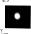
- the transmitted light of the optical element 10 maintains a circular shape (see FIG. 8A ).
- the shape of the light from the light source changes as the light transmits through the optical element 10.
- the optical element 10 can control a light distribution so that the transmitted light has a cross shape, for example (see FIG. 8B ).
- the shape of the transmitted light of the optical element 10 can be distributed in any shape between the shape shown in FIG. 8A and the shape shown in FIG. 8B .
- Two adjacent liquid crystal cells 100 of the plurality of liquid crystal cells 100 are bonded to each other via an optical elastic resin layer 160.
- a translucent adhesive containing an acrylic resin or an epoxy resin can be used for the optical elastic resin layer 160.
- the number of the liquid crystal cells 100 included in the optical element 10 is not limited to four. However, when the number of the liquid crystal cells 100 increases, the transmittance of the optical element 10 decreases. Therefore, it is preferable that the number of the liquid crystal cells 100 included in the optical element 10 is four.
- FIGS. 2A and 2B are schematic cross-sectional views of the optical element 10 according to an embodiment of the present invention.
- FIG. 2A is a schematic cross-sectional view in a zx plane taken along a line A1-A2 shown in FIG. 1
- FIG. 2B is a schematic cross-sectional view in a yz plane taken along a line B1-B2 shown in FIG. 1 .
- the x-axis direction and the y-axis direction may be described as a first direction and a second direction, respectively. That is, the second direction is a direction orthogonal to the first direction.
- each of the plurality of liquid crystal cells 100 includes a first substrate 110-1, a second substrate 110-2, a first transparent electrode 120-1, a second transparent electrode 120-2, a third transparent electrode 120-3, a fourth transparent electrode 120-4, a first alignment film 130-1, a second alignment film 130-2, a sealing member 140, and a liquid crystal layer 150.
- the first transparent electrode 120-1, the second transparent electrode 120-2, and the first alignment film 130-1 covering the first transparent electrode 120-1 and the second transparent electrode 120-2 are provided on the first substrate 110-1.
- the third transparent electrode 120-3, the fourth transparent electrode 120-4, and the second alignment film 130-2 covering the third transparent electrode 120-3 and the fourth transparent electrode 120-4 are provided on the second substrate 110-2.
- the first substrate 110-1 and the second substrate 110-2 are arranged so that the first transparent electrode 120-1 and the second transparent electrode 120-2 on the first substrate 110-1 and the third transparent electrode 120-3 and the fourth transparent electrode 120-4 on the second substrate 110-2 face each other. Further, the first substrate 110-1 and the second substrate 110-2 are bonded to each other via the sealing member 140 that is provided in the peripheral portion of the first substrate 110-1 and the second substrate 110-2. Furthermore, the liquid crystal layer 150 is provided between the first substrate 110-1 and the second substrate 110-2 by sealing a liquid crystal in a space surrounded by the first substrate 110-1 (more specifically, the first alignment film 130-1), the second substrate 110-2 (more specifically, the second alignment film 130-2), and the sealing member 140.
- a rigid substrate having light-transmitting properties such as a glass substrate, a quartz substrate, or a sapphire substrate is used as each of the first substrate 110-1 and the second substrate.
- a flexible substrate having light-transmitting properties such as a polyimide resin substrate, an acrylic resin substrate, a siloxane resin substrate, or a fluorine resin substrate can also be used as each of the first substrate 110-1 and the second substrate 110-2.
- Each of the first transparent electrode 120-1, the second transparent electrode 120-2, the third transparent electrode 120-3, and the fourth transparent electrode 120-4 functions as an electrode for forming an electric field in the liquid crystal layer 150.
- a transparent conductive material such as indium tin oxide (ITO) or indium zinc oxide (IZO) is used for each of the first transparent electrode 120-1, the second transparent electrode 120-2, the third transparent electrode 120-3, and the fourth transparent electrode 120-4.
- the liquid crystal layer 150 can refract transmitted light or change the polarization state of transmitted light according to the alignment state of the liquid crystal molecules.
- nematic liquid crystal can be used as the liquid crystal of the liquid crystal layer 150.
- a positive liquid crystal is described as the liquid crystal in the present embodiment, a negative liquid crystal can also be adopted by changing the initial alignment directions of the liquid crystal molecules.
- the liquid crystal preferably contains a chiral agent that imparts twist to the liquid crystal molecules.
- Each of the first alignment film 130-1 and the second alignment film 130-2 aligns the liquid crystal molecules in the liquid crystal layer 150 in a predetermined direction.
- a polyimide resin or the like can be used for each of the first alignment film 130-1 and the second alignment film 130-2.
- each of the first alignment film 130-1 and the second alignment film 130-2 may be imparted with alignment properties by an alignment treatment such as a rubbing method or a photo-alignment method.
- the rubbing method is a method of rubbing the surface of the alignment film in one direction.
- the photo-alignment method is a method of irradiating an alignment film with linearly polarized ultraviolet rays.
- An adhesive material containing epoxy resin, acrylic resin, or the like can be used for the sealing member 140.
- the adhesive material may be of an ultraviolet curable type or a heat curable type.
- the first liquid crystal cell 100-1, the second liquid crystal cell 100-2, the third liquid crystal cell 100-3, and the fourth liquid crystal cell 100-4 have the same basic structure.
- the arrangement of the transparent electrodes 120 and the alignment properties of the alignment films 130 are different from each other between the first liquid crystal cell 100-1, the second liquid crystal cell 100-2, the third liquid crystal cell 100-3, and the fourth liquid crystal cell 100-4.
- the first transparent electrode 120-1 and the second transparent electrode 120-2 extend in the x-axis direction
- the third transparent electrode 120-3 and the fourth transparent electrode 120-4 extend in the y-axis direction. That is, in the first liquid crystal cell 100-1 and the second liquid crystal cell 100-2, the extending direction of each of the first transparent electrode 120-1 and the second transparent electrode 120-2 is the x-axis direction, and the extending direction of each of the third transparent electrode 120-3 and the fourth transparent electrode 120-4 is the y-axis direction.
- the first transparent electrode 120-1 and the second transparent electrode 120-2 have a comb-teeth shape, and the first transparent electrode 120-1 and the second transparent electrode 120-2 are arranged alternately in the y-axis direction. Further, the third transparent electrode 120-3 and the fourth transparent electrode 120-4 have a comb-teeth shape, and the third transparent electrode 120-3 and the fourth transparent electrode 120-4 are arranged alternately in the x-axis direction.
- the first transparent electrode 120-1 and the second transparent electrode 120-2 extend in the y-axis direction
- the third transparent electrode 120-3 and the fourth transparent electrode 120-4 extend in the x-axis direction. That is, in the third liquid crystal cell 100-3 and the fourth liquid crystal cell 100-4, the extending direction of each of the first transparent electrode 120-1 and the second transparent electrode 120-2 is the y-axis direction, and the extending direction of each of the third transparent electrode 120-3 and the fourth transparent electrode 120-4 is the x-axis direction.
- the first transparent electrode 120-1 and the second transparent electrode 120-2 have a comb-teeth shape, and the first transparent electrode 120-1 and the second transparent electrode 120-2 are arranged alternately in the x-axis direction. Further, the third transparent electrode 120-3 and the fourth transparent electrode 120-4 have a comb-teeth shape, and the third transparent electrode 120-3 and the fourth transparent electrode 120-4 are arranged alternately in the y-axis direction.
- the extending direction of the first transparent electrode 120-1 and the second transparent electrode 120-2 is orthogonal to the extending direction of the third transparent electrode 120-3 and the fourth transparent electrode 120-4, the extending directions may intersect with a slight deviation (within approximately ⁇ 10 degrees) from orthogonality.
- the optical element 10 can control a distribution of unpolarized light by including at least two liquid crystal cells 100. Therefore, the optical element 10 does not require providing a pair of polarizing plates that, for example, are provided on the front and back surfaces of the liquid crystal display element.
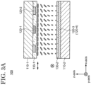
- FIGS. 3A to 3D are schematic cross-sectional views illustrating alignment directions of liquid crystal molecules in the liquid crystal layer 150 of the liquid crystal cell 100 and properties of light transmitting through the liquid crystal cell 100 of the optical element 10 according to an embodiment of the present invention.
- the first transparent electrode 120-1 and the second transparent electrode 120-2 extend in the y-axis direction
- the third transparent electrode 120-3 and the fourth transparent electrode 120-4 extend in the x-axis direction.
- FIG. 3A shows the liquid crystal cell 100 in a state where no voltages are applied to the transparent electrodes 120.
- the first alignment film 130-1 is aligned in the x-axis direction. Therefore, the long axes of the liquid crystal molecules on the first alignment film 130-1 are aligned along the x-axis direction. In other words, the initial alignment direction of the liquid crystal molecules closer to the first substrate 110-1 is the x-axis direction.
- the second alignment film 130-2 is aligned in the y-axis direction. Therefore, the long axes of the liquid crystal molecules on the second alignment film 130-2 are aligned along the y-axis direction. In other words, the initial alignment direction of the liquid crystal molecules closer to the second substrate 110-2 is the y-axis direction.
- the liquid crystal molecules in the liquid crystal layer 150 rotate little by little continuously from the first substrate 110-1 to the second substrate 110-2 and their directions of the long axes change from the x-direction to the y-axis direction, viewed from the thickness direction (z-axis direction) of the liquid crystal layer 150.
- the liquid crystal layer 150 is in the above state, it is said that the liquid crystal layer 150 is in a twisted state.
- the polarization axis of light transmitting through the liquid crystal layer 150 is rotated from the x-axis direction to the y-axis direction according to the alignment directions of the liquid crystal molecules. That is, the polarization component of the light transmitting through the liquid crystal layer 150 is rotated. In other words, the light transmitting through the liquid crystal layer 150 has optical rotation.
- FIG. 3B shows the liquid crystal cell 100 of FIG. 3A in a state where voltages are applied to the transparent electrodes 120.
- high voltages (H) are applied to the first transparent electrode 120-1 and the third transparent electrode 120-3
- low voltages (L) are applied to the second transparent electrode 120-2 and the fourth transparent electrode 120-4. That is, voltages are applied so that a potential difference is generated between two adjacent transparent electrodes 120.
- the electric field generated between two adjacent transparent electrodes 120 may be referred to as a lateral electric field.
- the liquid crystal molecules closer to the first substrate 110-1 are aligned in a convex arc shape in the x-axis direction with respect to the first substrate 110-1 by the influence of the lateral electric field between the first transparent electrode 120-1 and the second transparent electrode 120-2. Further, the liquid crystal molecules closer to the second substrate 110-2 are aligned in a convex arc shape in the y-axis direction with respect to the second substrate 110-2 by the influence of the lateral electric field between the third transparent electrode 120-3 and the fourth transparent electrode 120-4.
- the alignment direction of the liquid crystal molecules in the center between the first substrate 110-1 and the second substrate 110-2 are hardly changed due to any lateral electric field.
- the first substrate 110-1 and the second substrate 110-2 are far apart with a sufficient inter-substrate distance, the lateral electric field between the first transparent electrode 120-1 and the second transparent electrode 120-2 of the first substrate 110-1 does not affect the alignment of the liquid crystal molecules on the side of the second substrate 110-2, or is negligibly small.
- the lateral electric field between the third transparent electrode 120-3 and the fourth transparent electrode 120-4 of the second substrate 110-2 does not affect the alignment of the liquid crystal molecules on the side of the first substrate 110-1, or is negligibly small. Therefore, the liquid crystal molecules in the twisted state before the generation of the lateral electric field maintain the twisted state even after the generation of the lateral electric field as shown in FIG. 3B , and the liquid crystal layer 150 has a refractive index distribution. In this case, the light transmitting through the liquid crystal layer 150 has optical rotation while diffusing the polarization component in the direction parallel to the alignment directions of the liquid crystal molecules.
- the light emitted from the light source has a polarization component in the x-axis direction (P-polarization component) and a polarization component in the y-axis direction (S-polarization component).
- P-polarization component polarization component in the x-axis direction
- S-polarization component polarization component in the y-axis direction
- the polarization component of the light is divided into the P-polarization component and the S-polarization component in the following description. That is, the light emitted from the light source includes a first polarized light 1000-1 having the P-polarization component and a second polarized light 1000-2 having the S-polarization component (see (1) in FIG. 3B ).
- the first polarized light 1000-1 incident on the liquid crystal cell 100 is the same as the alignment direction of the liquid crystal molecules on the side of the first substrate 110-1, the first polarized light 1000-1 is diffused in the x-axis direction according to the refractive index distribution of the liquid crystal molecules (see (2) in FIG. 3B ).
- the first polarized light 1000-1 travels from the first substrate 110-1 to the second substrate 110-2, the first polarized light 1000-1 undergoes optical rotation, and the polarized light component changes from the P-polarization component to the S-polarization component.
- the first polarized light 1000-1 Since the S-polarization component of the first polarized light 1000-1 is the same as the alignment direction of the liquid crystal molecules on the side of the second substrate 110-2, the first polarized light 1000-1 is diffused in the y-axis direction according to the refractive index distribution of the liquid crystal molecules (see (3) in Figure 3B ). Further, the first polarized light 1000-1 emitted from the liquid crystal cell 100 has the S-polarization component (see (4) in FIG. 3B ).
- the second polarized light 1000-2 is not diffused (See (2) in FIG. 3B ).
- the second polarized light 1000-2 travels from the first substrate 110-1 to the second substrate 110-2, the second polarized light 1000-2 undergoes optical rotation, and the polarization component changes from the S-polarization component to the P-polarization component.
- the second polarized light 1000-2 having the P-polarization component is different from the alignment direction of the liquid crystal molecules on the side of the second substrate 110-2, the second polarized light 1000-2 is not diffused (see (3) in FIG. 3B ). Further, the second polarized light 1000-2 emitted from the liquid crystal cell 100 has the P-polarization component (see (4) in FIG. 3B ).
- FIG. 3C shows the liquid crystal cell 100 in which no voltages are applied to the transparent electrodes 120.
- the rubbing treatment is performed on the first alignment film 130-1 in the x-axis direction.
- the rubbing treatment is performed on the second alignment film 130-2 in the x-axis direction. Therefore, the long axes of the liquid crystal molecules on the second alignment film 130-2 are aligned along the x-axis direction. In other words, the alignment directions of the liquid crystal molecules closer to the second substrate 110-2 are the x-axis direction.
- the liquid crystal molecules in the liquid crystal layer 150 are not changed to smoothly align from the first substrate 110-1 to the second substrate 110-2 as shown in FIG. 3A .
- the liquid crystal layer 150 is in the above state, it is said that the liquid crystal layer 150 is not in a twisted state. In this case, the polarization component of the light transmitting through the liquid crystal layer 150 is not rotated. In other words, the light transmitting through the liquid crystal layer 150 does not have optical rotation.
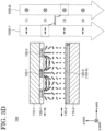
- FIG. 3D shows the liquid crystal cell 100 of FIG. 3C in a state where voltages are applied to the transparent electrodes 120.
- the liquid crystal molecules closer to the first substrate 110-1 are aligned in a convex arc shape in the x-axis direction with respect to the first substrate 110-1 by the influence of the lateral electric field between the first transparent electrode 120-1 and the second transparent electrode 120-2.
- the liquid crystal molecules closer to the second substrate 110-2 rotate so as to change their long axes in the y-axis direction and are aligned in a convex arc shape in the y-axis direction with respect to the second substrate 110-2 by the influence of the lateral electric field between the third transparent electrode 120-3 and the fourth transparent electrode 120-4.
- the liquid crystal molecules in the center between the first substrate 110-1 and the second substrate 110-2 are far away with a sufficient inter-substrate distance, the alignment of the liquid crystal molecules are hardly changed due to any lateral electric field on the side of the first substrate 110-2 or on the side of the second substrate 110-2. Therefore, in the liquid crystal cell 100 shown in FIG. 3D , even when the liquid crystal molecules closer to the first substrate 110-1 and the liquid crystal molecules closer to the second substrate 110-2 are aligned in the x-axis direction and the y-axis direction, respectively, the liquid crystal molecules in the liquid crystal layer 150 do not rotate little by little continuously from the first substrate 110-2 to the second substrate 110-2.
- the alignment state is only changed separately on the side of each substrate 110. Therefore, the liquid crystal molecules not in the twisted state before the generation of the lateral electric field maintain their not twisted state even after the generation of the lateral electric field as shown in FIG. 3D , and the liquid crystal layer 150 has a refractive index distribution. In this way, when the alignment directions of the liquid crystal molecules are discontinuously changed when viewed from the thickness direction of the liquid crystal layer 150, the light transmitting through the liquid crystal layer 150 does not have optical rotation while diffusing the polarization component in the direction parallel to the alignment directions of the liquid crystal molecules.
- the case in which the light transmits through the liquid crystal cell 100 shown in FIG. 3D is described in detail.
- the P-polarization component of the first polarized light 1000-1 incident on the liquid crystal cell 100 is the same as the alignment direction of the liquid crystal molecules on the side of the first substrate 110-1, the first polarized light 1000-1 is diffused in the x-axis direction according to the refractive index distribution of the liquid crystal molecules (see (2) in FIG. 3D ). Since the first polarized light 1000-1 traveling from the first substrate 110-1 to the second substrate 110-2 does not undergo optical rotation, the first polarized light 1000-1 maintains the P-polarization component.
- the first polarized light 1000-1 Since the P-polarization component of the first polarized light 1000-1 is different from the alignment direction of the liquid crystal molecules on the side of the second substrate 110-2, the first polarized light 1000-1 is not diffused (see (3) in FIG. 3D ). Further, the first polarized light 1000-1 emitted from the liquid crystal cell 100 has the P polarized light component (see (4) in FIG. 3D ).
- the second polarized light 1000-2 is not diffused (See (2) in FIG. 3D ).
- the second polarized light 1000-2 traveling from the first substrate 110-1 to the second substrate 110-2 does not undergo optical rotation, the second polarized light 1000-2 maintains the S-polarization component.
- the second polarized light 1000-2 having the S-polarization component is the same as the alignment direction of the liquid crystal molecules on the side of the second substrate 110-2, the second polarized light 1000-2 is diffused in the y-axis direction according to the refractive index distribution of the liquid crystal molecules (see (3) in FIG. 3D ). Further, the second polarized light 1000-2 emitted from the liquid crystal cell 100 has the S-polarization component (see (4) in FIG. 3D ).
- the alignment of the liquid crystal molecules in the liquid crystal layer 150 can be controlled by the extending direction of the transparent electrode 120, the rubbing direction of the alignment film 130, and the voltages applied to the transparent electrodes 120. Therefore, the optical element 10 can diffuse light in a predetermined direction by using the optical rotation and refractive index distribution of liquid crystal molecules of each of the plurality of liquid crystal cells 100.
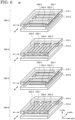
- FIG. 4 is a schematic diagram illustrating a relationship between the extending direction of the transparent electrodes 120 and the alignment directions of the liquid crystal molecules on the transparent electrodes 120 in a state where no voltages are applied to the transparent electrode 120 of the optical element 10 according to an embodiment of the present invention. Arrows in FIG. 4 indicate alignment directions of the liquid crystal molecules closer to each substrate 110. Table 1 shows each parameter of the optical element 10 shown in FIG. 4 .
- the liquid crystal molecules closer to the first substrate 110-1 are aligned in a convex arc shape in the y-axis direction, and the liquid crystal molecules closer to the second substrate 110-2 rotate from the y-axis direction to the x-axis direction to be aligned in a convex arc shape in the x-axis direction. Since the liquid crystal molecules in the first liquid crystal cell 100-1 are not in a twisted state, the liquid crystal layer 150 does not have optical rotation.
- the liquid crystal molecules closer to the first substrate 110-1 rotate from the x-axis direction to the y-axis direction to be aligned in a convex arc shape in the y-axis direction, and the liquid crystal molecules closer to the second substrate 110-2 are aligned in a convex arc shape in the x-axis direction. Since the liquid crystal molecules in the second liquid crystal cell 100-2 are not in a twisted state, the liquid crystal layer 150 does not have optical rotation.
- the liquid crystal molecules closer to the first substrate 110-1 rotate from the y-axis direction to the x-axis direction to be aligned in a convex arc shape in the x-axis direction, and the liquid crystal molecules closer to the second substrate 110-2 are aligned in a convex arc shape in the y-axis direction. Since the liquid crystal molecules in the third liquid crystal cell 100-3 are not in a twisted state, the liquid crystal layer 150 does not have optical rotation.
- the liquid crystal molecules closer to the first substrate 110-1 are aligned in a convex arc shape in the x-axis direction, and the liquid crystal molecules closer to the second substrate 110-2 rotate from the x-axis direction to the y-axis direction to be aligned in a convex arc shape in the y-axis direction. Since the liquid crystal molecules in the fourth liquid crystal cell 100-4 are not in a twisted state, the liquid crystal layer 150 does not have optical rotation. Therefore, when light transmits through the optical element 10, the P-polarization component and the S-polarization component of the light at the time of incidence on the optical element 10 are controlled as shown in Table 2.
- the P-polarization component of the incident light is diffused four times in the x-axis direction
- the S-polarized light component is diffused four times in the y-axis direction.
- both the P-polarization component and the S-polarization component are diffused not only on the side of the first substrate 110-1 but also on the side of the second substrate 110-2.
- a light distribution having a cross shape can be obtained by increasing the number of times of diffusion compared to the conventional optical element. Therefore, color unevenness in the light distribution having a cross shape can be suppressed. Further, since the number of times of diffusion can be increased without increasing the number of liquid crystal cells 100 in the optical element 10, a decrease in transmittance and an increase in manufacturing cost can be suppressed.
- An optical element 20 according to an embodiment of the present invention is described with reference to FIG. 5 .
- the description of the configuration of the optical element 20 may be omitted.
- FIG. 5 is a schematic diagram illustrating a relationship between extending directions of transparent electrodes 220 and alignment directions of liquid crystal molecules on the transparent electrodes 220 in a state where no voltages are applied to the transparent electrode 220 of the optical element 20 according to an embodiment of the present invention.
- a first liquid crystal cell 200-1, a second liquid crystal cell 200-2, a third liquid crystal cell 200-3, and a fourth liquid crystal cell 200-4 of the optical element 20 a first transparent electrode 220-1 and a second transparent electrode 220-2 are provided on a first substrate 210-1 and a third transparent electrode 220-3 and a fourth transparent electrode 220-4 are provided on the second substrate 210-2.
- Table 3 shows each parameter of the optical element 20 shown in FIG. 5 .
- [Table 3] extending direction of transparent electrode initial alignment direction of liquid crystal molecules first liquid crystal cell first substrate side x-axis direction y-axis direction second substrate side x-axis direction y-axis direction second liquid first substrate side y-axis direction x-axis direction crystal cell second substrate side y-axis direction x-axis direction third liquid crystal cell first substrate side x-axis direction y-axis direction second substrate side x-axis direction y-axis direction fourth liquid crystal cell first substrate side y-axis direction x-axis direction second substrate side y-axis direction x-axis direction x-axis direction
- the third liquid crystal cell 200-3 and the fourth liquid crystal cell 200-4 have the same structure as the first liquid crystal cell 200-1 and the second liquid crystal cell 200-2, respectively.
- the optical element 20 has a structure in which the first liquid crystal cells 200-1 and the second liquid crystal cell 200-2 are alternately stacked.
- the liquid crystal molecules closer to each of the first substrate 210-1 and the second substrate 210-2 are aligned in a convex arc shape in the y-axis direction. Since the liquid crystal molecules in the first liquid crystal cell 200-1 are not in a twisted state, the liquid crystal layer does not have optical rotation.
- the liquid crystal molecules closer to each of the first substrate 210-1 and the second substrate 210-2 are aligned in a convex arc shape in the x-axis direction. Since the liquid crystal molecules in the second liquid crystal cell 200-2 are not in a twisted state, the liquid crystal layer does not have optical rotation.
- the third liquid crystal cell 200-3 and the fourth liquid crystal cell 200-4 have the same configuration as the first liquid crystal cell 200-1 and the second liquid crystal cell 200-2, respectively. Therefore, when light transmits through the optical element 20, the P-polarization component and the S-polarization component of the light at the time of incidence on the optical element 20 are controlled as shown in Table 4.
- the P-polarization component of the incident light is diffused four times in the x-axis direction
- the S-polarized light component is diffused four times in the y-axis direction.
- both the P-polarization component and the S-polarization component are diffused not only on the side of the first substrate 210-1 but also on the side of the second substrate 210-2.
- a light distribution having a cross shape can be obtained by increasing the number of times of diffusion compared to the conventional optical element. Therefore, color unevenness in the light distribution having a cross shape can be suppressed. Further, since the number of times of diffusion can be increased without increasing the number of liquid crystal cells 200 in the optical element 20, a decrease in transmittance and an increase in manufacturing cost can be suppressed.
- An optical element 30 according to an embodiment of the present invention is described with reference to FIG. 6 .
- the description of the configuration of the optical element 30 may be omitted.
- FIG. 6 is a schematic diagram illustrating a relationship between extending directions of transparent electrodes 320 and alignment directions of liquid crystal molecules on the transparent electrodes 320 in a state where no voltages are applied to the transparent electrode 320 of the optical element 30 according to an embodiment of the present invention.
- a first liquid crystal cell 300-1, a second liquid crystal cell 300-2, a third liquid crystal cell 300-3, and a fourth liquid crystal cell 300-4 of the optical element 30 a first transparent electrode 320-1 and a second transparent electrode 320-2 are provided on a first substrate 310-1 and a third transparent electrode 320-3 and a fourth transparent electrode 320-4 are provided on the second substrate 310-2.
- Table 6 indicate the alignment directions (the initial alignment directions) of the liquid crystal molecules closer to each substrate 310.
- Table 6 shows each parameter of the optical element 30 shown in FIG. 6 .
- [Table 5] extending direction of transparent electrode initial alignment direction of liquid crystal molecules first liquid crystal cell first substrate side x-axis direction x-axis direction second substrate side x-axis direction y-axis direction second liquid crystal cell first substrate side y-axis direction x-axis direction second substrate side y-axis direction y-axis direction third liquid crystal cell first substrate side x-axis direction x-axis direction second substrate side x-axis direction y-axis direction fourth liquid crystal cell first substrate side y-axis direction x-axis direction second substrate side y-axis direction y-axis direction
- the third liquid crystal cell 300-3 and the fourth liquid crystal cell 300-4 have the same structure as the first liquid crystal cell 300-1 and the second liquid crystal cell 300-2, respectively.
- the optical element 30 has a structure in which the first liquid crystal cells 300-1 and the second liquid crystal cell 300-2 are alternately stacked.
- the liquid crystal molecules closer to the first substrate 310-1 rotate from the x-axis direction to the y-axis direction to be aligned in a convex arc shape in the y-axis direction, and the liquid crystal molecules closer to the second substrate 310-2 are aligned in a convex arc shape in the y-axis direction. Since the liquid crystal molecules in the first liquid crystal cell 300-1 are not in a twisted state, the liquid crystal layer does not have optical rotation.
- the liquid crystal molecules closer to the first substrate 310-1 are aligned in a convex arc shape in the x-axis direction, and the liquid crystal molecules closer to the second substrate 310-2 rotate from the y-axis direction to the x-axis direction to be aligned in a convex arc shape in the x-axis direction. Since the liquid crystal molecules in the second liquid crystal cell 300-2 are not in a twisted state, the liquid crystal layer does not have optical rotation.
- the third liquid crystal cell 300-3 and the fourth liquid crystal cell 300-4 have the same configuration as the first liquid crystal cell 300-1 and the second liquid crystal cell 300-2, respectively.
- the P-polarization component of the incident light is diffused four times in the x-axis direction
- the S-polarized light component is diffused four times in the y-axis direction.
- both the P-polarization component and the S-polarization component are diffused not only on the side of the first substrate 310-1 but also on the side of the second substrate 310-2.
- a light distribution having a cross shape can be obtained by increasing the number of times of diffusion compared to the conventional optical element. Therefore, color unevenness in the light distribution having a cross shape can be suppressed. Further, since the number of times of diffusion can be increased without increasing the number of liquid crystal cells 300 in the optical element 30, a decrease in transmittance and an increase in manufacturing cost can be suppressed.
- a shape of the light distribution obtained by the optical element 30 is not limited to the cross shape.
- various shapes of the light distribution can be obtained. For example, in each of the first liquid crystal cell 300-1 and the second liquid crystal cell 300-2, high voltages are applied to the first transparent electrode 320-1 and the third transparent electrode 320-3, and low voltages are applied to the second transparent electrode 320-2 and the fourth transparent electrode 320-4. Further, in the third liquid crystal cell 300-3, no voltages are applied to the first transparent electrode 320-1 and the second transparent electrode 320-2, and a high voltage and a low voltage are applied to the third transparent electrode 320-3 and the fourth transparent electrode 320-4, respectively.
- a high voltage and a low voltage are applied to the first transparent electrode 320-1 and the second transparent electrode 320-2, respectively, and no voltages are applied to the third transparent electrode 320-3 and the fourth transparent electrode 320-4.
- the liquid crystal molecules closer to the first substrate 310-1 rotate from the x-direction to the y-axis direction so as to be aligned in a convex arc shape in the y-axis direction, and the liquid crystal molecules closer to the second substrate 310-2 are aligned in a convex arc shape in the y-axis direction. Since the liquid crystal molecules in the first liquid crystal cell 300-1 are not in a twisted state, the liquid crystal layer does not have optical rotation.
- the liquid crystal molecules closer to the first substrate 310-1 are aligned in a convex arc shape in the x-axis direction, and the liquid crystal molecules closer to the second substrate 310-2 rotate from the y-axis direction to the x-axis direction so as to be aligned in a convex arc shape in the x-axis direction. Since the liquid crystal molecules in the second liquid crystal cell 300-2 are not in a twisted state, the liquid crystal layer does not have optical rotation.
- the liquid crystal molecules closer to the first substrate 310-1 are aligned in the x-direction, and the liquid crystal molecules closer to the second substrate 310-2 are aligned in a convex arc shape in the y-direction. Since the liquid crystal molecules in the third liquid crystal cell 300-3 are in a twisted state, the liquid crystal layer has optical rotation.
- the liquid crystal molecules closer to the first substrate 310-1 are aligned in a convex arc in the y-axis direction, and the liquid crystal molecules closer to the second substrate 310-2 are aligned in the x-axis direction.
- the liquid crystal layer Since the liquid crystal molecules in the fourth liquid crystal cell 300-4 are in a twisted state, the liquid crystal layer has optical rotation. Therefore, when light transmits through the optical element 30, the P-polarization component and the S-polarization component of the light at the time of incidence on the optical element 30 are controlled as shown in Table 7.
- the P-polarization component of the incident light is diffused three times and the S-polarization component of the incident light is diffused three times. Specifically, the P-polarization is diffused twice and once in the x-axis direction and the y-axis direction, respectively.
- the S-polarization component is diffused once and twice in the x-axis direction and the y-axis direction, respectively.
- Both the P-polarization component and the S-polarization component are diffused not only in the x-axis direction but also in the y-axis direction, and the number of times of the diffusion each in the x-axis direction and the y-axis direction is the same, so that a light distribution having a circular shape is obtained.
- a shape of the light distribution obtained by the optical element 30 is not limited to the circular shape.
- the first liquid crystal cell 300-1 and the third liquid crystal cell 300-3 no voltages are applied to the first transparent electrode 320-1 and the second transparent electrode 320-2, and a high voltage and a low voltage are applied to the third transparent electrode 320-3 and the fourth transparent electrode 320-4, respectively.
- the second liquid crystal cell 300-2 and the fourth liquid crystal cell 300-4 high voltages are applied to the first transparent electrode 320-1 and the third transparent electrode 320-3, and low voltages are applied to the second transparent electrode 320-2 and the fourth transparent electrodes 320-4.
- the liquid crystal molecules closer to the first substrate 310-1 are aligned in the x-axis direction, and the liquid crystal molecules closer to the second substrate 310-2 are aligned in a convex arc shape in the y-axis direction. Since the liquid crystal molecules in the first liquid crystal cell 300-1 are in a twisted state, the liquid crystal layer has optical rotation.
- the third liquid crystal cell 300-3 and the fourth liquid crystal cell 300-4 have the same configuration as the first liquid crystal cell 300-1 and the second liquid crystal cell 300-2, respectively.
- the P-polarization component of the incident light is diffused three times and the S-polarization component of the incident light is diffused three times. Specifically, the P-polarization is diffused twice and once in the x-axis direction and the y-axis direction, respectively.
- the S-polarization component is diffused twice and once in the x-axis direction and the y-axis direction, respectively.
- Both the P-polarization component and the S-polarization component are diffused not only in the x-axis direction but also in the y-axis direction, and the number of times of the diffusion in the x-axis direction is more than the number of times of the diffusion in the y-axis direction, so that a light distribution having an elliptical shape is obtained.
- An optical element 40 according to an embodiment of the present invention is described with reference to FIG. 7 .
- the description of the configuration of the optical element 40 may be omitted.
- FIG. 7 is a schematic diagram illustrating a relationship between extending directions of transparent electrodes 420 and alignment directions of liquid crystal molecules on the transparent electrodes 420 in a state where no voltages are applied to the transparent electrode 420 of the optical element 40 according to an embodiment of the present invention.
- a first liquid crystal cell 400-1, a second liquid crystal cell 400-2, a third liquid crystal cell 400-3, and a fourth liquid crystal cell 400-4 of the optical element 40 a first transparent electrode 420-1 and a second transparent electrode 420-2 are provided on a first substrate 410-1 and a third transparent electrode 420-3 and a fourth transparent electrode 420-4 are provided on the second substrate 410-2.
- Table 9 shows each parameter of the optical element 30 shown in FIG. 6 .
- [Table 9] extending direction of transparent electrode initial alignment direction of liquid crystal molecules first liquid crystal cell first substrate side x-axis direction y-axis direction second substrate side x-axis direction y-axis direction second liquid crystal cell first substrate side y-axis direction x-axis direction second substrate side y-axis direction x-axis direction third liquid crystal cell first substrate side x-axis direction x-axis direction second substrate side x-axis direction y-axis direction fourth liquid crystal cell first substrate side y-axis direction x-axis direction second substrate side y-axis direction y-axis direction y-axis direction
- the liquid crystal molecules closer to the first substrate 410-1 are aligned in a convex arc shape in the y-axis direction, and the liquid crystal molecules closer to the second substrate 410-2 are aligned in the y-axis direction. Since the liquid crystal molecules in the first liquid crystal cell 400-1 are not in a twisted state, the liquid crystal layer does not have optical rotation.
- the liquid crystal molecules closer to the first substrate 410-1 are aligned in a convex arc shape in the x-axis direction, and the liquid crystal molecules closer to the second substrate 410-2 are aligned in a convex arc shape in the x-axis direction. Since the liquid crystal molecules in the second liquid crystal cell 400-2 are not in a twisted state, the liquid crystal layer does not have optical rotation.
- the liquid crystal molecules closer to the first substrate 410-1 rotate from the x-axis direction to the y-axis direction to be aligned in a convex arc shape in the y-axis direction, and the liquid crystal molecules closer to the second substrate 410-2 are aligned in a convex arc shape in the y-axis direction. Since the liquid crystal molecules in the third liquid crystal cell 400-3 are not in a twisted state, the liquid crystal layer does not have optical rotation.
- the liquid crystal molecules closer to the first substrate 410-1 are aligned in a convex arc shape in the x-axis direction, and the liquid crystal molecules closer to the second substrate 410-2 rotate from the y-axis direction to the x-axis direction to be aligned in a convex arc shape in the x-axis direction. Since the liquid crystal molecules in the fourth liquid crystal cell 400-4 are not in a twisted state, the liquid crystal layer does not have optical rotation. Therefore, when light transmits through the optical element 40, the P-polarization component and the S-polarization component of the light at the time of incidence on the optical element 40 are controlled as shown in Table 10.
- the P-polarization component of the incident light is diffused four times in the x-axis direction
- the S-polarized light component is diffused four times in the y-axis direction.
- both the P-polarization component and the S-polarization component are diffused not only on the side of the first substrate 410-1 but also on the side of the second substrate 410-2.
- a light distribution having a cross shape can be obtained by increasing the number of times of diffusion compared to the conventional optical element. Therefore, color unevenness in the light distribution having a cross shape can be suppressed. Further, since the number of times of diffusion can be increased without increasing the number of liquid crystal cells 400 in the optical element 40, a decrease in transmittance and an increase in manufacturing cost can be suppressed.
- a shape of the light distribution obtained by the optical element 40 is not limited to the cross shape.
- various shapes of the light distribution can be obtained. For example, in each of the first liquid crystal cell 400-1 and the second liquid crystal cell 400-2, high voltages are applied to the first transparent electrode 420-1 and the third transparent electrode 420-3, and low voltages are applied to the second transparent electrode 420-2 and the fourth transparent electrode 420-4. Further, in the third liquid crystal cell 400-3, no voltages are applied to the first transparent electrode 420-1 and the second transparent electrode 420-2, and a high voltage and a low voltage are applied to the third transparent electrode 420-3 and the fourth transparent electrode 420-4, respectively.
- a high voltage and a low voltage are applied to the first transparent electrode 420-1 and the second transparent electrode 420-2, respectively, and no voltages are applied to the third transparent electrode 420-3 and the fourth transparent electrode 420-4.
- the liquid crystal molecules closer to the first substrate 410-1 are aligned in a convex arc shape in the y-axis direction, and the liquid crystal molecules closer to the second substrate 410-2 are aligned in a convex arc shape in the y-axis direction. Since the liquid crystal molecules in the first liquid crystal cell 400-1 are not in a twisted state, the liquid crystal layer does not have optical rotation.
- the liquid crystal molecules closer to the first substrate 410-1 are aligned in a convex arc shape in the x-axis direction, and the liquid crystal molecules closer to the second substrate 410-2 are aligned in a convex arc shape in the x-axis direction. Since the liquid crystal molecules in the second liquid crystal cell 400-2 are not in a twisted state, the liquid crystal layer does not have optical rotation.
- the liquid crystal molecules closer to the first substrate 410-1 are aligned in the x-direction, and the liquid crystal molecules closer to the second substrate 410-2 are aligned in a convex arc shape in the y-direction.
- the liquid crystal layer Since the liquid crystal molecules in the third liquid crystal cell 400-3 are in a twisted state, the liquid crystal layer has optical rotation.
- the liquid crystal molecules closer to the first substrate 410-1 are aligned in a convex arc in the x-axis direction, and the liquid crystal molecules closer to the second substrate 410-2 are aligned in the y-axis direction. Since the liquid crystal molecules in the fourth liquid crystal cell 400-4 are in a twisted state, the liquid crystal layer has optical rotation. Therefore, when light transmits through the optical element 40, the P-polarization component and the S-polarization component of the light at the time of incidence on the optical element 30 are controlled as shown in Table 11.
- the P-polarization component of the incident light is diffused three times and the S-polarization component of the incident light is diffused three times. Specifically, the P-polarization is diffused twice and once in the x-axis direction and the y-axis direction, respectively.
- the S-polarization component is diffused once and twice in the x-axis direction and the y-axis direction, respectively.
- Both the P-polarization component and the S-polarization component are diffused not only in the x-axis direction but also in the y-axis direction, and the number of times of the diffusion each in the x-axis direction and the y-axis direction is the same, so that a light distribution having a circular shape is obtained.
Landscapes
- Physics & Mathematics (AREA)
- Nonlinear Science (AREA)
- Mathematical Physics (AREA)
- Chemical & Material Sciences (AREA)
- Crystallography & Structural Chemistry (AREA)
- General Physics & Mathematics (AREA)
- Optics & Photonics (AREA)
- Spectroscopy & Molecular Physics (AREA)
- Geometry (AREA)
- Liquid Crystal (AREA)
Abstract
Description
- An embodiment of the present invention relates to an optical element that controls a distribution of light emitted from a light source.
- An optical element which is a so-called liquid crystal lens has been conventionally known in which a change in the refractive index of a liquid crystal is utilized by adjusting a voltage applied to the liquid crystal (for example, see
Patent Literature 1,Patent Literature 2, or Patent Literature 3). For example, the lighting devices disclosed in thePatent Literature 1 and thePatent Literature 2 use a liquid crystal lens to distribute light from a light source in a circular shape. Further, the beam shaping device disclosed in thePatent Literature 3 changes the distribution shape of light by changing patterns of an electrode applied to a liquid crystal. -
- Patent Literature 1:
Japanese laid-open patent publication No. 2005-317879 - Patent Literature 2:
Japanese laid-open patent publication No. 2010-230887 - Patent Literature 3:
Japanese laid-open patent publication No. 2014-160277 - For example, an optical element in which liquid crystal cells having a lens function are stacked can change the shape of light incident from a light source using the lens function and emit the light. However, when the shape of the light is changed, the emitted light may cause color unevenness. In particular, in an optical element that greatly changes the shape of light from a light source, when light transmitting through the optical element is irradiated on a wall or the like, color unevenness near the outline of the emitted light may become noticeable.
- In view of the above problem, one object of an embodiment of the present invention is to provide an optical element in which color unevenness in a light distribution is suppressed.
- An optical element according to an embodiment of the present invention includes a plurality of stacked liquid crystal cells. The plurality of liquid crystal cells each includes a first substrate on which a first transparent electrode, a second transparent electrode, and a first alignment film covering the first transparent electrode and the second transparent electrode are provided, a second substrate on which a third transparent electrode, a fourth transparent electrode, and a second alignment film covering the third transparent electrode and the second transparent electrode are provided, and a liquid crystal layer between the first substrate and the second substrate. The plurality of liquid crystal cells includes a first liquid crystal cell. The first liquid crystal cell includes the first transparent electrode and the second transparent electrode extending in a first direction, the third transparent electrode and the fourth transparent electrode extending in a second direction orthogonal to the first direction, the first alignment film aligning liquid crystal molecules in the liquid crystal layer in the second direction when no voltages are applied to the first transparent electrode and the second transparent electrode, and the second alignment film aligning liquid crystal molecules in the liquid crystal layer in the second direction when no voltages are applied to the third transparent electrode and the fourth transparent electrode.
- An optical element includes a plurality of stacked liquid crystal cells. The plurality of liquid crystal cells each includes a first substrate on which a first transparent electrode, a second transparent electrode, and a first alignment film covering the first transparent electrode and the second transparent electrode are provided, a second substrate on which a third transparent electrode, a fourth transparent electrode, and a second alignment film covering the third transparent electrode and the second transparent electrode are provided, and a liquid crystal layer between the first substrate and the second substrate. The plurality of liquid crystal cells includes a first liquid crystal cell. The first liquid crystal cell includes the first transparent electrode and the second transparent electrode extending in a first direction, the third transparent electrode and the fourth transparent electrode extending in the first direction, the first alignment film aligning liquid crystal molecules in the liquid crystal layer in a second direction orthogonal to the first direction when no voltages are applied to the first transparent electrode and the second transparent electrode, and the second alignment film aligning liquid crystal molecules in the liquid crystal layer in the second direction when no voltages are applied to the third transparent electrode and the fourth transparent electrode.
- An optical element includes a plurality of stacked liquid crystal cells. The plurality of liquid crystal cells each includes a first substrate on which a first transparent electrode, a second transparent electrode, and a first alignment film covering the first transparent electrode and the second transparent electrode are provided, a second substrate on which a third transparent electrode, a fourth transparent electrode, and a second alignment film covering the third transparent electrode and the second transparent electrode are provided, and a liquid crystal layer between the first substrate and the second substrate. The plurality of liquid crystal cells includes a first liquid crystal cell. The first liquid crystal cell includes the first transparent electrode and the second transparent electrode extending in a first direction, the third transparent electrode and the fourth transparent electrode extending in the first direction, the first alignment film aligning liquid crystal molecules in the liquid crystal layer in a second direction orthogonal to the first direction when no voltages are applied to the first transparent electrode and the second transparent electrode, and the second alignment film aligning liquid crystal molecules in the liquid crystal layer in the first direction when no voltages are applied to the third transparent electrode and the fourth transparent electrode.
-
-
FIG. 1 is a schematic perspective view of an optical element according to an embodiment of the present invention. -
FIG. 2A is a schematic cross-sectional view of an optical element according to an embodiment of the present invention. -
FIG. 2B is a schematic cross-sectional view of an optical element according to an embodiment of the present invention. -
FIG. 3A is a schematic cross-sectional view illustrating alignment directions of liquid crystal molecules in a liquid crystal layer of a liquid crystal cell and properties of light transmitting through the liquid crystal cell of an optical element according to an embodiment of the present invention. -
FIG. 3B is a schematic cross-sectional view illustrating alignment directions of liquid crystal molecules in a liquid crystal layer of a liquid crystal cell and properties of light transmitting through the liquid crystal cell of an optical element according to an embodiment of the present invention. -
FIG. 3C is a schematic cross-sectional view illustrating alignment directions of liquid crystal molecules in a liquid crystal layer of a liquid crystal cell and properties of light transmitting through the liquid crystal cell of an optical element according to an embodiment of the present invention. -
FIG. 3D is a schematic cross-sectional view illustrating alignment directions of liquid crystal molecules in a liquid crystal layer of a liquid crystal cell and properties of light transmitting through the liquid crystal cell of an optical element according to an embodiment of the present invention. -
FIG. 4 is a schematic diagram illustrating a relationship between extending directions of transparent electrodes and alignment directions of liquid crystal molecules on the transparent electrodes in a state where no voltages are applied to the transparent electrode of an optical element according to an embodiment of the present invention.
element according to an embodiment of the present invention. -
FIG. 5 is a schematic diagram illustrating a relationship between extending directions of transparent electrodes and alignment directions of liquid crystal molecules on the transparent electrodes in a state where no voltages are applied to the transparent electrode of an optical element according to an embodiment of the present invention. -
FIG. 6 is a schematic diagram illustrating a relationship between extending directions of transparent electrodes and alignment directions of liquid crystal molecules on the transparent electrodes in a state where no voltages are applied to the transparent electrode of an optical element according to an embodiment of the present invention. -
FIG. 7 is a schematic diagram illustrating a relationship between extending directions of transparent electrodes and alignment directions of liquid crystal molecules on the transparent electrodes in a state where no voltages are applied to the transparent electrode of an optical element according to an embodiment of the present invention. -
FIG. 8A is a photograph showing transmitted light of an optical element according to an embodiment of the present invention. -
FIG. 8B is a photograph showing a cross-shaped light distribution obtained by controlling an optical element according to an embodiment of the present invention. - Hereinafter, each of the embodiments of the present invention is described with reference to the drawings. However, the present invention can be implemented in various modes without departing from the gist of the invention and should not be interpreted as being limited to the description of the embodiments exemplified below.
- Although the drawings may be schematically represented in terms of width, thickness, shape, and the like of each part as compared with their actual mode in order to make explanation clearer, they are only an example and an interpretation of the present invention is not limited. In addition, in the drawings, the same reference numerals are provided to the same elements as those described previously with reference to preceding figures and repeated explanations may be omitted accordingly.
- In the case when a single film is processed to form a plurality of structural bodies, each structural body may have different functions and roles, and the bases formed beneath each structural body may also be different. However, the plurality of structural bodies is derived from films formed in the same layer by the same process and have the same material. Therefore, the plurality of these films is defined as existing in the same layer.
- When expressing a mode in which another structure is arranged over a certain structure, in the case where it is simply described as "over", unless otherwise noted, a case where another structure is arranged directly over a certain structure as if in contact with that structure, and a case where another structure is arranged via another structure over a certain structure, are both included.
- An
optical element 10 according to an embodiment of the present invention is described with reference toFIGS. 1 to 4 . -
FIG. 1 is a schematic perspective view of theoptical element 10 according to an embodiment of the present invention. As shown inFIG. 1 , theoptical element 10 includes a plurality of liquid crystal cells 100 (a first liquid crystal cell 100-1, a second liquid crystal cell 100-2, a third liquid crystal cell 100-3, and a fourth liquid crystal cell 100-4) stacked in the z-axis direction. Although not shown in the figures, a light source is placed above the first liquid crystal cell 100-1. Therefore, light emitted from the light source transmits through the first liquid crystal cell 100-1, the second liquid crystal cell 100-2, the third liquid crystal cell 100-3, and the fourth liquid crystal cell 100-4 in order. - Light from the light source transmits through the
optical element 10. At this time, when no voltages are applied to electrodes of each liquid crystal cell 100 (details of the electrodes are described later.), the light from the light source transmits through theoptical element 10 without changing its shape. For example, when the light from the light source has a circular shape, the transmitted light of theoptical element 10 maintains a circular shape (seeFIG. 8A ). On the other hand, when voltages are applied to the electrodes of eachliquid crystal cell 100, the shape of the light from the light source changes as the light transmits through theoptical element 10. When the light from the light source has a circular shape, theoptical element 10 can control a light distribution so that the transmitted light has a cross shape, for example (seeFIG. 8B ). In addition, when the voltages applied to the electrodes of eachliquid crystal cell 100 are adjusted, the shape of the transmitted light of theoptical element 10 can be distributed in any shape between the shape shown inFIG. 8A and the shape shown inFIG. 8B . - Two adjacent
liquid crystal cells 100 of the plurality ofliquid crystal cells 100 are bonded to each other via an opticalelastic resin layer 160. For example, a translucent adhesive containing an acrylic resin or an epoxy resin can be used for the opticalelastic resin layer 160. - Although four
liquid crystal cells 100 are shown inFIG. 1 , the number of theliquid crystal cells 100 included in theoptical element 10 is not limited to four. However, when the number of theliquid crystal cells 100 increases, the transmittance of theoptical element 10 decreases. Therefore, it is preferable that the number of theliquid crystal cells 100 included in theoptical element 10 is four. -
FIGS. 2A and2B are schematic cross-sectional views of theoptical element 10 according to an embodiment of the present invention. Specifically,FIG. 2A is a schematic cross-sectional view in a zx plane taken along a line A1-A2 shown inFIG. 1 , andFIG. 2B is a schematic cross-sectional view in a yz plane taken along a line B1-B2 shown inFIG. 1 . In addition, hereinafter, the x-axis direction and the y-axis direction may be described as a first direction and a second direction, respectively. That is, the second direction is a direction orthogonal to the first direction. - As shown in
FIGS. 2A and2B , each of the plurality ofliquid crystal cells 100 includes a first substrate 110-1, a second substrate 110-2, a first transparent electrode 120-1, a second transparent electrode 120-2, a third transparent electrode 120-3, a fourth transparent electrode 120-4, a first alignment film 130-1, a second alignment film 130-2, a sealingmember 140, and aliquid crystal layer 150. The first transparent electrode 120-1, the second transparent electrode 120-2, and the first alignment film 130-1 covering the first transparent electrode 120-1 and the second transparent electrode 120-2 are provided on the first substrate 110-1. Further, the third transparent electrode 120-3, the fourth transparent electrode 120-4, and the second alignment film 130-2 covering the third transparent electrode 120-3 and the fourth transparent electrode 120-4 are provided on the second substrate 110-2. The first substrate 110-1 and the second substrate 110-2 are arranged so that the first transparent electrode 120-1 and the second transparent electrode 120-2 on the first substrate 110-1 and the third transparent electrode 120-3 and the fourth transparent electrode 120-4 on the second substrate 110-2 face each other. Further, the first substrate 110-1 and the second substrate 110-2 are bonded to each other via the sealingmember 140 that is provided in the peripheral portion of the first substrate 110-1 and the second substrate 110-2. Furthermore, theliquid crystal layer 150 is provided between the first substrate 110-1 and the second substrate 110-2 by sealing a liquid crystal in a space surrounded by the first substrate 110-1 (more specifically, the first alignment film 130-1), the second substrate 110-2 (more specifically, the second alignment film 130-2), and the sealingmember 140. - For example, a rigid substrate having light-transmitting properties such as a glass substrate, a quartz substrate, or a sapphire substrate is used as each of the first substrate 110-1 and the second substrate. Further, a flexible substrate having light-transmitting properties such as a polyimide resin substrate, an acrylic resin substrate, a siloxane resin substrate, or a fluorine resin substrate can also be used as each of the first substrate 110-1 and the second substrate 110-2.
- Each of the first transparent electrode 120-1, the second transparent electrode 120-2, the third transparent electrode 120-3, and the fourth transparent electrode 120-4 functions as an electrode for forming an electric field in the
liquid crystal layer 150. For example, a transparent conductive material such as indium tin oxide (ITO) or indium zinc oxide (IZO) is used for each of the first transparent electrode 120-1, the second transparent electrode 120-2, the third transparent electrode 120-3, and the fourth transparent electrode 120-4. - The
liquid crystal layer 150 can refract transmitted light or change the polarization state of transmitted light according to the alignment state of the liquid crystal molecules. For example, nematic liquid crystal can be used as the liquid crystal of theliquid crystal layer 150. Although a positive liquid crystal is described as the liquid crystal in the present embodiment, a negative liquid crystal can also be adopted by changing the initial alignment directions of the liquid crystal molecules. Further, the liquid crystal preferably contains a chiral agent that imparts twist to the liquid crystal molecules. - Each of the first alignment film 130-1 and the second alignment film 130-2 aligns the liquid crystal molecules in the
liquid crystal layer 150 in a predetermined direction. For example, a polyimide resin or the like can be used for each of the first alignment film 130-1 and the second alignment film 130-2. In addition, each of the first alignment film 130-1 and the second alignment film 130-2 may be imparted with alignment properties by an alignment treatment such as a rubbing method or a photo-alignment method. The rubbing method is a method of rubbing the surface of the alignment film in one direction. The photo-alignment method is a method of irradiating an alignment film with linearly polarized ultraviolet rays. - An adhesive material containing epoxy resin, acrylic resin, or the like can be used for the sealing
member 140. The adhesive material may be of an ultraviolet curable type or a heat curable type. - As described above, the first liquid crystal cell 100-1, the second liquid crystal cell 100-2, the third liquid crystal cell 100-3, and the fourth liquid crystal cell 100-4 have the same basic structure. However, the arrangement of the transparent electrodes 120 and the alignment properties of the
alignment films 130 are different from each other between the first liquid crystal cell 100-1, the second liquid crystal cell 100-2, the third liquid crystal cell 100-3, and the fourth liquid crystal cell 100-4. - In the first liquid crystal cell 100-1 and the second liquid crystal cell 100-2, the first transparent electrode 120-1 and the second transparent electrode 120-2 extend in the x-axis direction, and the third transparent electrode 120-3 and the fourth transparent electrode 120-4 extend in the y-axis direction. That is, in the first liquid crystal cell 100-1 and the second liquid crystal cell 100-2, the extending direction of each of the first transparent electrode 120-1 and the second transparent electrode 120-2 is the x-axis direction, and the extending direction of each of the third transparent electrode 120-3 and the fourth transparent electrode 120-4 is the y-axis direction. The first transparent electrode 120-1 and the second transparent electrode 120-2 have a comb-teeth shape, and the first transparent electrode 120-1 and the second transparent electrode 120-2 are arranged alternately in the y-axis direction. Further, the third transparent electrode 120-3 and the fourth transparent electrode 120-4 have a comb-teeth shape, and the third transparent electrode 120-3 and the fourth transparent electrode 120-4 are arranged alternately in the x-axis direction.
- In the third liquid crystal cell 100-3 and the fourth liquid crystal cell 100-4, the first transparent electrode 120-1 and the second transparent electrode 120-2 extend in the y-axis direction, and the third transparent electrode 120-3 and the fourth transparent electrode 120-4 extend in the x-axis direction. That is, in the third liquid crystal cell 100-3 and the fourth liquid crystal cell 100-4, the extending direction of each of the first transparent electrode 120-1 and the second transparent electrode 120-2 is the y-axis direction, and the extending direction of each of the third transparent electrode 120-3 and the fourth transparent electrode 120-4 is the x-axis direction. The first transparent electrode 120-1 and the second transparent electrode 120-2 have a comb-teeth shape, and the first transparent electrode 120-1 and the second transparent electrode 120-2 are arranged alternately in the x-axis direction. Further, the third transparent electrode 120-3 and the fourth transparent electrode 120-4 have a comb-teeth shape, and the third transparent electrode 120-3 and the fourth transparent electrode 120-4 are arranged alternately in the y-axis direction.
- In addition, although the extending direction of the first transparent electrode 120-1 and the second transparent electrode 120-2 is orthogonal to the extending direction of the third transparent electrode 120-3 and the fourth transparent electrode 120-4, the extending directions may intersect with a slight deviation (within approximately ±10 degrees) from orthogonality.
- Further, the
optical element 10 can control a distribution of unpolarized light by including at least twoliquid crystal cells 100. Therefore, theoptical element 10 does not require providing a pair of polarizing plates that, for example, are provided on the front and back surfaces of the liquid crystal display element. - Here, properties of light transmitting through the
liquid crystal cell 100 are described with reference toFIGS. 3A to 3D . -
FIGS. 3A to 3D are schematic cross-sectional views illustrating alignment directions of liquid crystal molecules in theliquid crystal layer 150 of theliquid crystal cell 100 and properties of light transmitting through theliquid crystal cell 100 of theoptical element 10 according to an embodiment of the present invention. In theliquid crystal cell 100 shown inFIGS. 3A to 3D , the first transparent electrode 120-1 and the second transparent electrode 120-2 extend in the y-axis direction, and the third transparent electrode 120-3 and the fourth transparent electrode 120-4 extend in the x-axis direction. -
FIG. 3A shows theliquid crystal cell 100 in a state where no voltages are applied to the transparent electrodes 120. The first alignment film 130-1 is aligned in the x-axis direction. Therefore, the long axes of the liquid crystal molecules on the first alignment film 130-1 are aligned along the x-axis direction. In other words, the initial alignment direction of the liquid crystal molecules closer to the first substrate 110-1 is the x-axis direction. The second alignment film 130-2 is aligned in the y-axis direction. Therefore, the long axes of the liquid crystal molecules on the second alignment film 130-2 are aligned along the y-axis direction. In other words, the initial alignment direction of the liquid crystal molecules closer to the second substrate 110-2 is the y-axis direction. In this way, when the initial alignment directions of the liquid crystal molecules intersect between the substrates 110 of the liquid crystal cell 100 (or the alignment directions of thealignment films 130 intersect), the liquid crystal molecules in theliquid crystal layer 150 rotate little by little continuously from the first substrate 110-1 to the second substrate 110-2 and their directions of the long axes change from the x-direction to the y-axis direction, viewed from the thickness direction (z-axis direction) of theliquid crystal layer 150. In addition, hereinafter, when theliquid crystal layer 150 is in the above state, it is said that theliquid crystal layer 150 is in a twisted state. In this case, the polarization axis of light transmitting through theliquid crystal layer 150 is rotated from the x-axis direction to the y-axis direction according to the alignment directions of the liquid crystal molecules. That is, the polarization component of the light transmitting through theliquid crystal layer 150 is rotated. In other words, the light transmitting through theliquid crystal layer 150 has optical rotation. -
FIG. 3B shows theliquid crystal cell 100 ofFIG. 3A in a state where voltages are applied to the transparent electrodes 120. For example, high voltages (H) are applied to the first transparent electrode 120-1 and the third transparent electrode 120-3, and low voltages (L) are applied to the second transparent electrode 120-2 and the fourth transparent electrode 120-4. That is, voltages are applied so that a potential difference is generated between two adjacent transparent electrodes 120. In addition, hereinafter, the electric field generated between two adjacent transparent electrodes 120 may be referred to as a lateral electric field. - The liquid crystal molecules closer to the first substrate 110-1 are aligned in a convex arc shape in the x-axis direction with respect to the first substrate 110-1 by the influence of the lateral electric field between the first transparent electrode 120-1 and the second transparent electrode 120-2. Further, the liquid crystal molecules closer to the second substrate 110-2 are aligned in a convex arc shape in the y-axis direction with respect to the second substrate 110-2 by the influence of the lateral electric field between the third transparent electrode 120-3 and the fourth transparent electrode 120-4. At this time, the alignment direction of the liquid crystal molecules in the center between the first substrate 110-1 and the second substrate 110-2 (the liquid crystal molecules located near the top of the liquid crystal molecules in the above-mentioned convex arc shape) are hardly changed due to any lateral electric field. In addition, since the first substrate 110-1 and the second substrate 110-2 are far apart with a sufficient inter-substrate distance, the lateral electric field between the first transparent electrode 120-1 and the second transparent electrode 120-2 of the first substrate 110-1 does not affect the alignment of the liquid crystal molecules on the side of the second substrate 110-2, or is negligibly small. Similarly, the lateral electric field between the third transparent electrode 120-3 and the fourth transparent electrode 120-4 of the second substrate 110-2 does not affect the alignment of the liquid crystal molecules on the side of the first substrate 110-1, or is negligibly small. Therefore, the liquid crystal molecules in the twisted state before the generation of the lateral electric field maintain the twisted state even after the generation of the lateral electric field as shown in
FIG. 3B , and theliquid crystal layer 150 has a refractive index distribution. In this case, the light transmitting through theliquid crystal layer 150 has optical rotation while diffusing the polarization component in the direction parallel to the alignment directions of the liquid crystal molecules. - Further, the case in which the light transmits through the
liquid crystal cell 100 shown inFIG. 3B is described in detail. The light emitted from the light source has a polarization component in the x-axis direction (P-polarization component) and a polarization component in the y-axis direction (S-polarization component). However, for convenience, the polarization component of the light is divided into the P-polarization component and the S-polarization component in the following description. That is, the light emitted from the light source includes a first polarized light 1000-1 having the P-polarization component and a second polarized light 1000-2 having the S-polarization component (see (1) inFIG. 3B ). - In
FIG. 3B , since the P-polarization component of the first polarized light 1000-1 incident on theliquid crystal cell 100 is the same as the alignment direction of the liquid crystal molecules on the side of the first substrate 110-1, the first polarized light 1000-1 is diffused in the x-axis direction according to the refractive index distribution of the liquid crystal molecules (see (2) inFIG. 3B ). When the first polarized light 1000-1 travels from the first substrate 110-1 to the second substrate 110-2, the first polarized light 1000-1 undergoes optical rotation, and the polarized light component changes from the P-polarization component to the S-polarization component. Since the S-polarization component of the first polarized light 1000-1 is the same as the alignment direction of the liquid crystal molecules on the side of the second substrate 110-2, the first polarized light 1000-1 is diffused in the y-axis direction according to the refractive index distribution of the liquid crystal molecules (see (3) inFigure 3B ). Further, the first polarized light 1000-1 emitted from theliquid crystal cell 100 has the S-polarization component (see (4) inFIG. 3B ). - In contrast, since the S-polarization component of the second polarized light 1000-2 incident on the
liquid crystal cell 100 is different from the alignment direction of the liquid crystal molecules on the side of the first substrate 110-1, the second polarized light 1000-2 is not diffused (See (2) inFIG. 3B ). When the second polarized light 1000-2 travels from the first substrate 110-1 to the second substrate 110-2, the second polarized light 1000-2 undergoes optical rotation, and the polarization component changes from the S-polarization component to the P-polarization component. Since the second polarized light 1000-2 having the P-polarization component is different from the alignment direction of the liquid crystal molecules on the side of the second substrate 110-2, the second polarized light 1000-2 is not diffused (see (3) inFIG. 3B ). Further, the second polarized light 1000-2 emitted from theliquid crystal cell 100 has the P-polarization component (see (4) inFIG. 3B ). - Next, a configuration of an alignment of the liquid crystal molecules different from the above-mentioned alignment is described.
-
FIG. 3C shows theliquid crystal cell 100 in which no voltages are applied to the transparent electrodes 120. As the above-described, the rubbing treatment is performed on the first alignment film 130-1 in the x-axis direction. On the other hand, unlike the above-described treatment, the rubbing treatment is performed on the second alignment film 130-2 in the x-axis direction. Therefore, the long axes of the liquid crystal molecules on the second alignment film 130-2 are aligned along the x-axis direction. In other words, the alignment directions of the liquid crystal molecules closer to the second substrate 110-2 are the x-axis direction. In this way, when the initial alignment directions of the liquid crystal molecules do not intersect between the substrates 110 of the liquid crystal cell 100 (or the alignment direction of the first alignment film 130-1 and the alignment direction of the second alignment film 130-2 do not intersect), the liquid crystal molecules in theliquid crystal layer 150 are not changed to smoothly align from the first substrate 110-1 to the second substrate 110-2 as shown inFIG. 3A . In addition, hereinafter, when theliquid crystal layer 150 is in the above state, it is said that theliquid crystal layer 150 is not in a twisted state. In this case, the polarization component of the light transmitting through theliquid crystal layer 150 is not rotated. In other words, the light transmitting through theliquid crystal layer 150 does not have optical rotation. -
FIG. 3D shows theliquid crystal cell 100 ofFIG. 3C in a state where voltages are applied to the transparent electrodes 120. The liquid crystal molecules closer to the first substrate 110-1 are aligned in a convex arc shape in the x-axis direction with respect to the first substrate 110-1 by the influence of the lateral electric field between the first transparent electrode 120-1 and the second transparent electrode 120-2. On the other hand, the liquid crystal molecules closer to the second substrate 110-2 rotate so as to change their long axes in the y-axis direction and are aligned in a convex arc shape in the y-axis direction with respect to the second substrate 110-2 by the influence of the lateral electric field between the third transparent electrode 120-3 and the fourth transparent electrode 120-4. At this time, since the liquid crystal molecules in the center between the first substrate 110-1 and the second substrate 110-2 are far away with a sufficient inter-substrate distance, the alignment of the liquid crystal molecules are hardly changed due to any lateral electric field on the side of the first substrate 110-2 or on the side of the second substrate 110-2. Therefore, in theliquid crystal cell 100 shown inFIG. 3D , even when the liquid crystal molecules closer to the first substrate 110-1 and the liquid crystal molecules closer to the second substrate 110-2 are aligned in the x-axis direction and the y-axis direction, respectively, the liquid crystal molecules in theliquid crystal layer 150 do not rotate little by little continuously from the first substrate 110-2 to the second substrate 110-2. In this case, optically, the alignment state is only changed separately on the side of each substrate 110. Therefore, the liquid crystal molecules not in the twisted state before the generation of the lateral electric field maintain their not twisted state even after the generation of the lateral electric field as shown inFIG. 3D , and theliquid crystal layer 150 has a refractive index distribution. In this way, when the alignment directions of the liquid crystal molecules are discontinuously changed when viewed from the thickness direction of theliquid crystal layer 150, the light transmitting through theliquid crystal layer 150 does not have optical rotation while diffusing the polarization component in the direction parallel to the alignment directions of the liquid crystal molecules. - Further, the case in which the light transmits through the
liquid crystal cell 100 shown inFIG. 3D is described in detail. InFIG. 3D , since the P-polarization component of the first polarized light 1000-1 incident on theliquid crystal cell 100 is the same as the alignment direction of the liquid crystal molecules on the side of the first substrate 110-1, the first polarized light 1000-1 is diffused in the x-axis direction according to the refractive index distribution of the liquid crystal molecules (see (2) inFIG. 3D ). Since the first polarized light 1000-1 traveling from the first substrate 110-1 to the second substrate 110-2 does not undergo optical rotation, the first polarized light 1000-1 maintains the P-polarization component. Since the P-polarization component of the first polarized light 1000-1 is different from the alignment direction of the liquid crystal molecules on the side of the second substrate 110-2, the first polarized light 1000-1 is not diffused (see (3) inFIG. 3D ). Further, the first polarized light 1000-1 emitted from theliquid crystal cell 100 has the P polarized light component (see (4) inFIG. 3D ). - In contrast, since the S-polarization component of the second polarized light 1000-2 incident on the
liquid crystal cell 100 is different from the alignment direction of the liquid crystal molecules on the side of the first substrate 110-1, the second polarized light 1000-2 is not diffused (See (2) inFIG. 3D ). When the second polarized light 1000-2 traveling from the first substrate 110-1 to the second substrate 110-2 does not undergo optical rotation, the second polarized light 1000-2 maintains the S-polarization component. Since the second polarized light 1000-2 having the S-polarization component is the same as the alignment direction of the liquid crystal molecules on the side of the second substrate 110-2, the second polarized light 1000-2 is diffused in the y-axis direction according to the refractive index distribution of the liquid crystal molecules (see (3) inFIG. 3D ). Further, the second polarized light 1000-2 emitted from theliquid crystal cell 100 has the S-polarization component (see (4) inFIG. 3D ). - As can be seen from the above, in the
liquid crystal cell 100, the alignment of the liquid crystal molecules in theliquid crystal layer 150 can be controlled by the extending direction of the transparent electrode 120, the rubbing direction of thealignment film 130, and the voltages applied to the transparent electrodes 120. Therefore, theoptical element 10 can diffuse light in a predetermined direction by using the optical rotation and refractive index distribution of liquid crystal molecules of each of the plurality ofliquid crystal cells 100. - Next, the extending directions of the transparent electrodes 120 and the alignment directions of the liquid crystal molecules in the
liquid crystal layer 150 in theoptical element 10 are described. -
FIG. 4 is a schematic diagram illustrating a relationship between the extending direction of the transparent electrodes 120 and the alignment directions of the liquid crystal molecules on the transparent electrodes 120 in a state where no voltages are applied to the transparent electrode 120 of theoptical element 10 according to an embodiment of the present invention. Arrows inFIG. 4 indicate alignment directions of the liquid crystal molecules closer to each substrate 110. Table 1 shows each parameter of theoptical element 10 shown inFIG. 4 .[Table 1] extending direction of transparent electrode initial alignment direction of liquid crystal molecules first liquid crystal cell first substrate side x-axis direction y-axis direction second substrate side y-axis direction y-axis direction second liquid crystal cell first substrate side x-axis direction x-axis direction second substrate side y-axis direction x-axis direction third liquid crystal cell first substrate side y-axis direction y-axis direction second substrate side x-axis direction y-axis direction fourth liquid crystal cell first substrate side y-axis direction x-axis direction second substrate side x-axis direction x-axis direction - In order to obtain a light distribution having a cross shape by the
optical element 10, in each of the first liquid crystal cell 100-1, the second liquid crystal cell 100-2, the third liquid crystal cell 100-3, and the fourth liquid crystal cell 100-4, high voltages are applied to the first transparent electrode 120-1 and the third transparent electrode 120-3, and low voltages are applied to the second transparent electrode 120-2 and the fourth transparent electrode 120-4. - In the first liquid crystal cell 100-1, when voltages are applied to the transparent electrodes 120 as described above, the liquid crystal molecules closer to the first substrate 110-1 are aligned in a convex arc shape in the y-axis direction, and the liquid crystal molecules closer to the second substrate 110-2 rotate from the y-axis direction to the x-axis direction to be aligned in a convex arc shape in the x-axis direction. Since the liquid crystal molecules in the first liquid crystal cell 100-1 are not in a twisted state, the
liquid crystal layer 150 does not have optical rotation. In the second liquid crystal cell 100-2, the liquid crystal molecules closer to the first substrate 110-1 rotate from the x-axis direction to the y-axis direction to be aligned in a convex arc shape in the y-axis direction, and the liquid crystal molecules closer to the second substrate 110-2 are aligned in a convex arc shape in the x-axis direction. Since the liquid crystal molecules in the second liquid crystal cell 100-2 are not in a twisted state, theliquid crystal layer 150 does not have optical rotation. In the third liquid crystal cell 100-3, the liquid crystal molecules closer to the first substrate 110-1 rotate from the y-axis direction to the x-axis direction to be aligned in a convex arc shape in the x-axis direction, and the liquid crystal molecules closer to the second substrate 110-2 are aligned in a convex arc shape in the y-axis direction. Since the liquid crystal molecules in the third liquid crystal cell 100-3 are not in a twisted state, theliquid crystal layer 150 does not have optical rotation. In the fourth liquid crystal cell 100-4, the liquid crystal molecules closer to the first substrate 110-1 are aligned in a convex arc shape in the x-axis direction, and the liquid crystal molecules closer to the second substrate 110-2 rotate from the x-axis direction to the y-axis direction to be aligned in a convex arc shape in the y-axis direction. Since the liquid crystal molecules in the fourth liquid crystal cell 100-4 are not in a twisted state, theliquid crystal layer 150 does not have optical rotation. Therefore, when light transmits through theoptical element 10, the P-polarization component and the S-polarization component of the light at the time of incidence on theoptical element 10 are controlled as shown in Table 2.[Table 2] P-polarization component S-polarization component first liquid crystal cell first substrate side - diffusion in the y-axis direction second substrate side diffusion in the x-axis direction - second liquid crystal cell first substrate side - diffusion in the y-axis direction second substrate side diffusion in the x-axis direction - third liquid crystal cell first substrate side diffusion in the x-axis direction - second substrate side - diffusion in the y-axis direction fourth liquid crystal cell first substrate side diffusion in the x-axis direction - second substrate side - diffusion in the y-axis direction - As can be seen from Table 2, in the
optical element 10, the P-polarization component of the incident light is diffused four times in the x-axis direction, and the S-polarized light component is diffused four times in the y-axis direction. Further, in theoptical element 10, both the P-polarization component and the S-polarization component are diffused not only on the side of the first substrate 110-1 but also on the side of the second substrate 110-2. - As described above, in the
optical element 10 according to an embodiment of the present invention, a light distribution having a cross shape can be obtained by increasing the number of times of diffusion compared to the conventional optical element. Therefore, color unevenness in the light distribution having a cross shape can be suppressed. Further, since the number of times of diffusion can be increased without increasing the number ofliquid crystal cells 100 in theoptical element 10, a decrease in transmittance and an increase in manufacturing cost can be suppressed. - <Second Embodiment>
- An
optical element 20 according to an embodiment of the present invention is described with reference toFIG. 5 . In the description, when a configuration of theoptical element 20 is similar to the configuration of theoptical element 10, the description of the configuration of theoptical element 20 may be omitted. -
FIG. 5 is a schematic diagram illustrating a relationship between extending directions of transparent electrodes 220 and alignment directions of liquid crystal molecules on the transparent electrodes 220 in a state where no voltages are applied to the transparent electrode 220 of theoptical element 20 according to an embodiment of the present invention. In each of a first liquid crystal cell 200-1, a second liquid crystal cell 200-2, a third liquid crystal cell 200-3, and a fourth liquid crystal cell 200-4 of theoptical element 20, a first transparent electrode 220-1 and a second transparent electrode 220-2 are provided on a first substrate 210-1 and a third transparent electrode 220-3 and a fourth transparent electrode 220-4 are provided on the second substrate 210-2. Arrows inFIG. 5 indicate the alignment directions (the initial alignment directions) of the liquid crystal molecules closer to each substrate 210. Table 3 shows each parameter of theoptical element 20 shown inFIG. 5 .[Table 3] extending direction of transparent electrode initial alignment direction of liquid crystal molecules first liquid crystal cell first substrate side x-axis direction y-axis direction second substrate side x-axis direction y-axis direction second liquid first substrate side y-axis direction x-axis direction crystal cell second substrate side y-axis direction x-axis direction third liquid crystal cell first substrate side x-axis direction y-axis direction second substrate side x-axis direction y-axis direction fourth liquid crystal cell first substrate side y-axis direction x-axis direction second substrate side y-axis direction x-axis direction - As can be seen from Table 3, the third liquid crystal cell 200-3 and the fourth liquid crystal cell 200-4 have the same structure as the first liquid crystal cell 200-1 and the second liquid crystal cell 200-2, respectively. In other words, the
optical element 20 has a structure in which the first liquid crystal cells 200-1 and the second liquid crystal cell 200-2 are alternately stacked. - In order to obtain a light distribution having a cross shape by the
optical element 20, in each of the first liquid crystal cell 200-1, the second liquid crystal cell 200-2, the third liquid crystal cell 200-3, and the fourth liquid crystal cell 200-4, high voltages are applied to the first transparent electrode 220-1 and the third transparent electrode 220-3, and low voltages are applied to the second transparent electrode 220-2 and the fourth transparent electrode 220-4. - In the first liquid crystal cell 200-1, when voltages are applied to the transparent electrodes 220 as described above, the liquid crystal molecules closer to each of the first substrate 210-1 and the second substrate 210-2 are aligned in a convex arc shape in the y-axis direction. Since the liquid crystal molecules in the first liquid crystal cell 200-1 are not in a twisted state, the liquid crystal layer does not have optical rotation. In the second liquid crystal cell 200-2, the liquid crystal molecules closer to each of the first substrate 210-1 and the second substrate 210-2 are aligned in a convex arc shape in the x-axis direction. Since the liquid crystal molecules in the second liquid crystal cell 200-2 are not in a twisted state, the liquid crystal layer does not have optical rotation. The third liquid crystal cell 200-3 and the fourth liquid crystal cell 200-4 have the same configuration as the first liquid crystal cell 200-1 and the second liquid crystal cell 200-2, respectively. Therefore, when light transmits through the
optical element 20, the P-polarization component and the S-polarization component of the light at the time of incidence on theoptical element 20 are controlled as shown in Table 4.[Table 4] P-polarization component S-polarization component first liquid crystal cell first substrate side - diffusion in the y-axis direction second substrate side - diffusion in the y-axis direction second liquid crystal cell first substrate side diffusion in the x-axis direction - second substrate side diffusion in the x-axis direction - third liquid crystal cell first substrate side - diffusion in the y-axis direction second substrate side - diffusion in the y-axis direction fourth liquid crystal cell first substrate side diffusion in the x-axis direction - second substrate side diffusion in the x-axis direction - - As can be seen from Table 4, in the
optical element 20, the P-polarization component of the incident light is diffused four times in the x-axis direction, and the S-polarized light component is diffused four times in the y-axis direction. Further, in theoptical element 10, both the P-polarization component and the S-polarization component are diffused not only on the side of the first substrate 210-1 but also on the side of the second substrate 210-2. - As described above, in the
optical element 20 according to an embodiment of the present invention, a light distribution having a cross shape can be obtained by increasing the number of times of diffusion compared to the conventional optical element. Therefore, color unevenness in the light distribution having a cross shape can be suppressed. Further, since the number of times of diffusion can be increased without increasing the number of liquid crystal cells 200 in theoptical element 20, a decrease in transmittance and an increase in manufacturing cost can be suppressed. - An
optical element 30 according to an embodiment of the present invention is described with reference toFIG. 6 . In the description, when a configuration of theoptical element 30 is similar to the configuration of theoptical element 10 or theoptical element 20, the description of the configuration of theoptical element 30 may be omitted. -
FIG. 6 is a schematic diagram illustrating a relationship between extending directions of transparent electrodes 320 and alignment directions of liquid crystal molecules on the transparent electrodes 320 in a state where no voltages are applied to the transparent electrode 320 of theoptical element 30 according to an embodiment of the present invention. In each of a first liquid crystal cell 300-1, a second liquid crystal cell 300-2, a third liquid crystal cell 300-3, and a fourth liquid crystal cell 300-4 of theoptical element 30, a first transparent electrode 320-1 and a second transparent electrode 320-2 are provided on a first substrate 310-1 and a third transparent electrode 320-3 and a fourth transparent electrode 320-4 are provided on the second substrate 310-2. Arrows inFIG. 6 indicate the alignment directions (the initial alignment directions) of the liquid crystal molecules closer to each substrate 310. Table 6 shows each parameter of theoptical element 30 shown inFIG. 6 .[Table 5] extending direction of transparent electrode initial alignment direction of liquid crystal molecules first liquid crystal cell first substrate side x-axis direction x-axis direction second substrate side x-axis direction y-axis direction second liquid crystal cell first substrate side y-axis direction x-axis direction second substrate side y-axis direction y-axis direction third liquid crystal cell first substrate side x-axis direction x-axis direction second substrate side x-axis direction y-axis direction fourth liquid crystal cell first substrate side y-axis direction x-axis direction second substrate side y-axis direction y-axis direction - As can be seen from Table 5, the third liquid crystal cell 300-3 and the fourth liquid crystal cell 300-4 have the same structure as the first liquid crystal cell 300-1 and the second liquid crystal cell 300-2, respectively. In other words, the
optical element 30 has a structure in which the first liquid crystal cells 300-1 and the second liquid crystal cell 300-2 are alternately stacked. - In order to obtain a light distribution having a cross shape by the
optical element 30, in each of the first liquid crystal cell 300-1, the second liquid crystal cell 300-2, the third liquid crystal cell 300-3, and the fourth liquid crystal cell 300-4, high voltages are applied to the first transparent electrode 320-1 and the third transparent electrode 320-3, and low voltages are applied to the second transparent electrode 320-2 and the fourth transparent electrode 320-4. - In the first liquid crystal cell 300-1, when voltages are applied to the transparent electrodes 320 as described above, the liquid crystal molecules closer to the first substrate 310-1 rotate from the x-axis direction to the y-axis direction to be aligned in a convex arc shape in the y-axis direction, and the liquid crystal molecules closer to the second substrate 310-2 are aligned in a convex arc shape in the y-axis direction. Since the liquid crystal molecules in the first liquid crystal cell 300-1 are not in a twisted state, the liquid crystal layer does not have optical rotation. In the second liquid crystal cell 300-2, the liquid crystal molecules closer to the first substrate 310-1 are aligned in a convex arc shape in the x-axis direction, and the liquid crystal molecules closer to the second substrate 310-2 rotate from the y-axis direction to the x-axis direction to be aligned in a convex arc shape in the x-axis direction. Since the liquid crystal molecules in the second liquid crystal cell 300-2 are not in a twisted state, the liquid crystal layer does not have optical rotation. The third liquid crystal cell 300-3 and the fourth liquid crystal cell 300-4 have the same configuration as the first liquid crystal cell 300-1 and the second liquid crystal cell 300-2, respectively. Therefore, when light transmits through the
optical element 30, the P-polarization component and the S-polarization component of the light at the time of incidence on theoptical element 30 are controlled as shown in Table 6.[Table 6] P-polarization component S-polarization component first liquid crystal cell first substrate side - diffusion in the y-axis direction second substrate side - diffusion in the y-axis direction second liquid crystal cell first substrate side diffusion in the x-axis direction - second substrate side diffusion in the x-axis direction - third liquid crystal cell first substrate side - diffusion in the y-axis direction second substrate side - diffusion in the y-axis direction fourth liquid crystal cell first substrate side diffusion in the x-axis direction - second substrate side diffusion in the x-axis direction - - As can be seen from Table 6, in the
optical element 30, the P-polarization component of the incident light is diffused four times in the x-axis direction, and the S-polarized light component is diffused four times in the y-axis direction. Further, in theoptical element 30, both the P-polarization component and the S-polarization component are diffused not only on the side of the first substrate 310-1 but also on the side of the second substrate 310-2. - As described above, in the
optical element 30 according to an embodiment of the present invention, a light distribution having a cross shape can be obtained by increasing the number of times of diffusion compared to the conventional optical element. Therefore, color unevenness in the light distribution having a cross shape can be suppressed. Further, since the number of times of diffusion can be increased without increasing the number of liquid crystal cells 300 in theoptical element 30, a decrease in transmittance and an increase in manufacturing cost can be suppressed. - A shape of the light distribution obtained by the
optical element 30 is not limited to the cross shape. When voltages applied to the transparent electrodes 320 are controlled, various shapes of the light distribution can be obtained. For example, in each of the first liquid crystal cell 300-1 and the second liquid crystal cell 300-2, high voltages are applied to the first transparent electrode 320-1 and the third transparent electrode 320-3, and low voltages are applied to the second transparent electrode 320-2 and the fourth transparent electrode 320-4. Further, in the third liquid crystal cell 300-3, no voltages are applied to the first transparent electrode 320-1 and the second transparent electrode 320-2, and a high voltage and a low voltage are applied to the third transparent electrode 320-3 and the fourth transparent electrode 320-4, respectively. Furthermore, in the fourth liquid crystal cell 300-4, a high voltage and a low voltage are applied to the first transparent electrode 320-1 and the second transparent electrode 320-2, respectively, and no voltages are applied to the third transparent electrode 320-3 and the fourth transparent electrode 320-4. - In the first liquid crystal cell 300-1, when voltages are applied to the transparent electrodes 320 as described above, the liquid crystal molecules closer to the first substrate 310-1 rotate from the x-direction to the y-axis direction so as to be aligned in a convex arc shape in the y-axis direction, and the liquid crystal molecules closer to the second substrate 310-2 are aligned in a convex arc shape in the y-axis direction. Since the liquid crystal molecules in the first liquid crystal cell 300-1 are not in a twisted state, the liquid crystal layer does not have optical rotation. In the second liquid crystal cell 300-2, the liquid crystal molecules closer to the first substrate 310-1 are aligned in a convex arc shape in the x-axis direction, and the liquid crystal molecules closer to the second substrate 310-2 rotate from the y-axis direction to the x-axis direction so as to be aligned in a convex arc shape in the x-axis direction. Since the liquid crystal molecules in the second liquid crystal cell 300-2 are not in a twisted state, the liquid crystal layer does not have optical rotation. In the third liquid crystal cell 300-3, the liquid crystal molecules closer to the first substrate 310-1 are aligned in the x-direction, and the liquid crystal molecules closer to the second substrate 310-2 are aligned in a convex arc shape in the y-direction. Since the liquid crystal molecules in the third liquid crystal cell 300-3 are in a twisted state, the liquid crystal layer has optical rotation. In the fourth liquid crystal cell 300-4, the liquid crystal molecules closer to the first substrate 310-1 are aligned in a convex arc in the y-axis direction, and the liquid crystal molecules closer to the second substrate 310-2 are aligned in the x-axis direction. Since the liquid crystal molecules in the fourth liquid crystal cell 300-4 are in a twisted state, the liquid crystal layer has optical rotation. Therefore, when light transmits through the
optical element 30, the P-polarization component and the S-polarization component of the light at the time of incidence on theoptical element 30 are controlled as shown in Table 7.[Table 7] P-polarization component S-polarization component first liquid crystal cell first substrate side - diffusion in the y-axis direction second substrate side - diffusion in the y-axis direction second liquid crystal cell first substrate side diffusion in the x-axis direction - second substrate side diffusion in the x-axis direction - third liquid crystal cell first substrate side - - second substrate side diffusion in the y-axis direction - fourth liquid crystal cell first substrate side - diffusion in the x-axis direction second substrate side - - - As can be seen from Table 7, when voltages applied to the transparent electrodes 320 are controlled in the
optical element 30, the P-polarization component of the incident light is diffused three times and the S-polarization component of the incident light is diffused three times. Specifically, the P-polarization is diffused twice and once in the x-axis direction and the y-axis direction, respectively. The S-polarization component is diffused once and twice in the x-axis direction and the y-axis direction, respectively. Both the P-polarization component and the S-polarization component are diffused not only in the x-axis direction but also in the y-axis direction, and the number of times of the diffusion each in the x-axis direction and the y-axis direction is the same, so that a light distribution having a circular shape is obtained. - A shape of the light distribution obtained by the
optical element 30 is not limited to the circular shape. For example, in the first liquid crystal cell 300-1 and the third liquid crystal cell 300-3, no voltages are applied to the first transparent electrode 320-1 and the second transparent electrode 320-2, and a high voltage and a low voltage are applied to the third transparent electrode 320-3 and the fourth transparent electrode 320-4, respectively. In the second liquid crystal cell 300-2 and the fourth liquid crystal cell 300-4, high voltages are applied to the first transparent electrode 320-1 and the third transparent electrode 320-3, and low voltages are applied to the second transparent electrode 320-2 and the fourth transparent electrodes 320-4. - In the first liquid crystal cell 300-1, when voltages are applied to the transparent electrodes 320 as described above, the liquid crystal molecules closer to the first substrate 310-1 are aligned in the x-axis direction, and the liquid crystal molecules closer to the second substrate 310-2 are aligned in a convex arc shape in the y-axis direction. Since the liquid crystal molecules in the first liquid crystal cell 300-1 are in a twisted state, the liquid crystal layer has optical rotation. The third liquid crystal cell 300-3 and the fourth liquid crystal cell 300-4 have the same configuration as the first liquid crystal cell 300-1 and the second liquid crystal cell 300-2, respectively. Therefore, when light transmits through the
optical element 30, the P-polarization component and the S-polarization component of the light at the time of incidence on theoptical element 30 are controlled as shown in Table 8.[Table 8] P-polarization component S-polarization component first liquid crystal cell first substrate side diffusion in the y-axis direction - second substrate side - diffusion in the x-axis direction second liquid crystal cell first substrate side - diffusion in the x-axis direction second substrate side - - third liquid crystal cell first substrate side - diffusion in the y-axis direction second substrate side diffusion in the x-axis direction - fourth liquid crystal cell first substrate side diffusion in the x-axis direction - second substrate side diffusion in the y-axis direction - - As can be seen from Table 8, when voltages applied to the transparent electrodes 320 are controlled in the
optical element 30, the P-polarization component of the incident light is diffused three times and the S-polarization component of the incident light is diffused three times. Specifically, the P-polarization is diffused twice and once in the x-axis direction and the y-axis direction, respectively. The S-polarization component is diffused twice and once in the x-axis direction and the y-axis direction, respectively. Both the P-polarization component and the S-polarization component are diffused not only in the x-axis direction but also in the y-axis direction, and the number of times of the diffusion in the x-axis direction is more than the number of times of the diffusion in the y-axis direction, so that a light distribution having an elliptical shape is obtained. - As described above in
Modification 1 andModification 2, not only the light distribution having a cross shape but also the light distribution having a circular shape or an elliptical shape can be obtained in theoptical element 30 according to an embodiment of the present invention. - An
optical element 40 according to an embodiment of the present invention is described with reference toFIG. 7 . In the description, when a configuration of theoptical element 40 is similar to theoptical element 10, theoptical element 20, or theoptical element 30, the description of the configuration of theoptical element 40 may be omitted. -
FIG. 7 is a schematic diagram illustrating a relationship between extending directions of transparent electrodes 420 and alignment directions of liquid crystal molecules on the transparent electrodes 420 in a state where no voltages are applied to the transparent electrode 420 of theoptical element 40 according to an embodiment of the present invention. In each of a first liquid crystal cell 400-1, a second liquid crystal cell 400-2, a third liquid crystal cell 400-3, and a fourth liquid crystal cell 400-4 of theoptical element 40, a first transparent electrode 420-1 and a second transparent electrode 420-2 are provided on a first substrate 410-1 and a third transparent electrode 420-3 and a fourth transparent electrode 420-4 are provided on the second substrate 410-2. Arrows inFIG. 7 indicate the alignment directions (the initial alignment directions) of the liquid crystal molecules closer to each substrate 410. Table 9 shows each parameter of theoptical element 30 shown inFIG. 6 .[Table 9] extending direction of transparent electrode initial alignment direction of liquid crystal molecules first liquid crystal cell first substrate side x-axis direction y-axis direction second substrate side x-axis direction y-axis direction second liquid crystal cell first substrate side y-axis direction x-axis direction second substrate side y-axis direction x-axis direction third liquid crystal cell first substrate side x-axis direction x-axis direction second substrate side x-axis direction y-axis direction fourth liquid crystal cell first substrate side y-axis direction x-axis direction second substrate side y-axis direction y-axis direction - In order to obtain a light distribution having a cross shape by the
optical element 40, in each of the first liquid crystal cell 400-1, the second liquid crystal cell 400-2, the third liquid crystal cell 400-3, and the fourth liquid crystal cell 400-4, high voltages are applied to the first transparent electrode 420-1 and the third transparent electrode 420-3, and low voltages are applied to the second transparent electrode 420-2 and the fourth transparent electrode 420-4. - In the first liquid crystal cell 400-1, when voltages are applied to the transparent electrodes 420 as described above, the liquid crystal molecules closer to the first substrate 410-1 are aligned in a convex arc shape in the y-axis direction, and the liquid crystal molecules closer to the second substrate 410-2 are aligned in the y-axis direction. Since the liquid crystal molecules in the first liquid crystal cell 400-1 are not in a twisted state, the liquid crystal layer does not have optical rotation. In the second liquid crystal cell 400-2, the liquid crystal molecules closer to the first substrate 410-1 are aligned in a convex arc shape in the x-axis direction, and the liquid crystal molecules closer to the second substrate 410-2 are aligned in a convex arc shape in the x-axis direction. Since the liquid crystal molecules in the second liquid crystal cell 400-2 are not in a twisted state, the liquid crystal layer does not have optical rotation. In the third liquid crystal cell 400-3, the liquid crystal molecules closer to the first substrate 410-1 rotate from the x-axis direction to the y-axis direction to be aligned in a convex arc shape in the y-axis direction, and the liquid crystal molecules closer to the second substrate 410-2 are aligned in a convex arc shape in the y-axis direction. Since the liquid crystal molecules in the third liquid crystal cell 400-3 are not in a twisted state, the liquid crystal layer does not have optical rotation. In the fourth liquid crystal cell 400-4, the liquid crystal molecules closer to the first substrate 410-1 are aligned in a convex arc shape in the x-axis direction, and the liquid crystal molecules closer to the second substrate 410-2 rotate from the y-axis direction to the x-axis direction to be aligned in a convex arc shape in the x-axis direction. Since the liquid crystal molecules in the fourth liquid crystal cell 400-4 are not in a twisted state, the liquid crystal layer does not have optical rotation. Therefore, when light transmits through the
optical element 40, the P-polarization component and the S-polarization component of the light at the time of incidence on theoptical element 40 are controlled as shown in Table 10.[Table 10] P-polarization component S-polarization component first liquid crystal cell first substrate side - diffusion in the y-axis direction second substrate side - diffusion in the y-axis direction second liquid crystal cell first substrate side diffusion in the x-axis direction - second substrate side diffusion in the x-axis direction - third liquid crystal cell first substrate side - diffusion in the y-axis direction second substrate side - diffusion in the y-axis direction fourth liquid crystal cell first substrate side diffusion in the x-axis direction - second substrate side diffusion in the x-axis direction - - As can be seen from Table 10, in the
optical element 40, the P-polarization component of the incident light is diffused four times in the x-axis direction, and the S-polarized light component is diffused four times in the y-axis direction. Further, in theoptical element 40, both the P-polarization component and the S-polarization component are diffused not only on the side of the first substrate 410-1 but also on the side of the second substrate 410-2. - As described above, in the
optical element 40 according to an embodiment of the present invention, a light distribution having a cross shape can be obtained by increasing the number of times of diffusion compared to the conventional optical element. Therefore, color unevenness in the light distribution having a cross shape can be suppressed. Further, since the number of times of diffusion can be increased without increasing the number of liquid crystal cells 400 in theoptical element 40, a decrease in transmittance and an increase in manufacturing cost can be suppressed. - A shape of the light distribution obtained by the
optical element 40 is not limited to the cross shape. When voltages applied to the transparent electrodes 420 are controlled, various shapes of the light distribution can be obtained. For example, in each of the first liquid crystal cell 400-1 and the second liquid crystal cell 400-2, high voltages are applied to the first transparent electrode 420-1 and the third transparent electrode 420-3, and low voltages are applied to the second transparent electrode 420-2 and the fourth transparent electrode 420-4. Further, in the third liquid crystal cell 400-3, no voltages are applied to the first transparent electrode 420-1 and the second transparent electrode 420-2, and a high voltage and a low voltage are applied to the third transparent electrode 420-3 and the fourth transparent electrode 420-4, respectively. Furthermore, in the fourth liquid crystal cell 400-4, a high voltage and a low voltage are applied to the first transparent electrode 420-1 and the second transparent electrode 420-2, respectively, and no voltages are applied to the third transparent electrode 420-3 and the fourth transparent electrode 420-4. - In the first liquid crystal cell 400-1, when voltages are applied to the transparent electrodes 420 as described above, the liquid crystal molecules closer to the first substrate 410-1 are aligned in a convex arc shape in the y-axis direction, and the liquid crystal molecules closer to the second substrate 410-2 are aligned in a convex arc shape in the y-axis direction. Since the liquid crystal molecules in the first liquid crystal cell 400-1 are not in a twisted state, the liquid crystal layer does not have optical rotation. In the second liquid crystal cell 400-2, the liquid crystal molecules closer to the first substrate 410-1 are aligned in a convex arc shape in the x-axis direction, and the liquid crystal molecules closer to the second substrate 410-2 are aligned in a convex arc shape in the x-axis direction. Since the liquid crystal molecules in the second liquid crystal cell 400-2 are not in a twisted state, the liquid crystal layer does not have optical rotation. In the third liquid crystal cell 400-3, the liquid crystal molecules closer to the first substrate 410-1 are aligned in the x-direction, and the liquid crystal molecules closer to the second substrate 410-2 are aligned in a convex arc shape in the y-direction. Since the liquid crystal molecules in the third liquid crystal cell 400-3 are in a twisted state, the liquid crystal layer has optical rotation. In the fourth liquid crystal cell 400-4, the liquid crystal molecules closer to the first substrate 410-1 are aligned in a convex arc in the x-axis direction, and the liquid crystal molecules closer to the second substrate 410-2 are aligned in the y-axis direction. Since the liquid crystal molecules in the fourth liquid crystal cell 400-4 are in a twisted state, the liquid crystal layer has optical rotation. Therefore, when light transmits through the
optical element 40, the P-polarization component and the S-polarization component of the light at the time of incidence on theoptical element 30 are controlled as shown in Table 11.[Table 11] P-polarization component S-polarization component first liquid crystal cell first substrate side - diffusion in the y-axis direction second substrate side - diffusion in the y-axis direction second liquid crystal cell first substrate side diffusion in the x-axis direction - second substrate side diffusion in the x-axis direction - third liquid crystal cell first substrate side - - second substrate side diffusion in the y-axis direction - fourth liquid crystal cell first substrate side - diffusion in the x-axis direction second substrate side - - - As can be seen from Table 11, when voltages applied to the transparent electrodes 420 are controlled in the
optical element 40, the P-polarization component of the incident light is diffused three times and the S-polarization component of the incident light is diffused three times. Specifically, the P-polarization is diffused twice and once in the x-axis direction and the y-axis direction, respectively. The S-polarization component is diffused once and twice in the x-axis direction and the y-axis direction, respectively. Both the P-polarization component and the S-polarization component are diffused not only in the x-axis direction but also in the y-axis direction, and the number of times of the diffusion each in the x-axis direction and the y-axis direction is the same, so that a light distribution having a circular shape is obtained. - As described above in the Modification section, not only the light distribution having a cross shape but also the light distribution having a circular shape can be obtained in the
optical element 40 according to an embodiment of the present invention. - Within the scope of the present invention, those skilled in the art may conceive of examples of changes and modifications, and it is understood that these examples of changes and modifications are also included within the scope of the present invention. For example, additions, deletions, or design changes of constituent elements, or additions, omissions, or changes to conditions of steps as appropriate based on the respective embodiments described above are also included within the scope of the present invention as long as the gist of the present invention is provided.
- Further, other effects which differ from those brought about by the embodiment, but which are apparent from the description herein or which can be readily predicted by those skilled in the art, are naturally understood to be brought about by the present invention.
-
- 10, 20, 30, 40: optical element,
- 100, 200, 300, 400: liquid crystal cell,
- 110, 210, 310, 410: substrate,
- 120, 220, 320, 420: transparent electrode,
- 130: alignment film,
- 140: sealing member,
- 150: liquid crystal layer,
- 160: optical elastic resin layer,
- 1000-1: first polarized light,
- 1000-2: second polarized light
Claims (11)
- An optical element comprising a plurality of stacked liquid crystal cells, the plurality of liquid crystal cells each comprising:a first substrate on which a first transparent electrode, a second transparent electrode, and a first alignment film covering the first transparent electrode and the second transparent electrode are provided;a second substrate on which a third transparent electrode, a fourth transparent electrode, and a second alignment film covering the third transparent electrode and the second transparent electrode are provided; anda liquid crystal layer between the first substrate and the second substrate,wherein the plurality of liquid crystal cells comprises a first liquid crystal cell, andthe first liquid crystal cell comprises:the first transparent electrode and the second transparent electrode extending in a first direction,the third transparent electrode and the fourth transparent electrode extending in a second direction orthogonal to the first direction,the first alignment film aligning liquid crystal molecules in the liquid crystal layer in the second direction when no voltages are applied to the first transparent electrode and the second transparent electrode, andthe second alignment film aligning liquid crystal molecules in the liquid crystal layer in the second direction when no voltages are applied to the third transparent electrode and the fourth transparent electrode.
- The optical element according to claim 1,wherein the plurality of liquid crystal cells comprises a second liquid crystal cell, andthe second liquid crystal cell comprises:the first transparent electrode and the second transparent electrode extending in the first direction,the third transparent electrode and the fourth transparent electrode extending in the second direction,the first alignment film aligning liquid crystal molecules in the liquid crystal layer in the first direction when no voltages are applied to the first transparent electrode and the second transparent electrode, andthe second alignment film aligning liquid crystal molecules in the liquid crystal layer in the first direction when no voltages are applied to the third transparent electrode and the fourth transparent electrode.
- The optical element according to claim 2,wherein the plurality of liquid crystal cells comprises a third liquid crystal cell, andthe third liquid crystal cell comprises:the first transparent electrode and the second transparent electrode extending in the second direction,the third transparent electrode and the fourth transparent electrode extending in the first direction,the first alignment film aligning liquid crystal molecules in the liquid crystal layer in the second direction when no voltages are applied to the first transparent electrode and the second transparent electrode, andthe second alignment film aligning liquid crystal molecules in the liquid crystal layer in the second direction when no voltages are applied to the third transparent electrode and the fourth transparent electrode.
- The optical element according to claim 3,wherein the plurality of liquid crystal cells comprises a fourth liquid crystal cell, andthe fourth liquid crystal cell comprises:the first transparent electrode and the second transparent electrode extending in the second direction,the third transparent electrode and the fourth transparent electrode extending in the first direction,the first alignment film aligning liquid crystal molecules in the liquid crystal layer in the first direction when no voltages are applied to the first transparent electrode and the second transparent electrode, andthe second alignment film aligning liquid crystal molecules in the liquid crystal layer in the first direction when no voltages are applied to the third transparent electrode and the fourth transparent electrode.
- An optical element comprising a plurality of stacked liquid crystal cells, the plurality of liquid crystal cells each comprising:a first substrate provided on a first transparent electrode, a second transparent electrode, and a first alignment film covering the first transparent electrode and the second transparent electrode;a second substrate provided on a third transparent electrode, a fourth transparent electrode, and a second alignment film covering the third transparent electrode and the second transparent electrode; anda liquid crystal layer between the first substrate and the second substrate,wherein the plurality of liquid crystal cells comprises a first liquid crystal cell, andthe first liquid crystal cell comprises:the first transparent electrode and the second transparent electrode extending in a first direction,the third transparent electrode and the fourth transparent electrode extending in the first direction,the first alignment film aligning liquid crystal molecules in the liquid crystal layer in a second direction orthogonal to the first direction when no voltages are applied to the first transparent electrode and the second transparent electrode, andthe second alignment film aligning liquid crystal molecules in the liquid crystal layer in the second direction when no voltages are applied to the third transparent electrode and the fourth transparent electrode.
- The optical element according to claim 5,wherein the plurality of liquid crystal cells comprises a second liquid crystal cell, andthe second liquid crystal cell comprises:the first transparent electrode and the second transparent electrode extending in the second direction,the third transparent electrode and the fourth transparent electrode extending in the second direction,the first alignment film aligning liquid crystal molecules in the liquid crystal layer in the first direction when no voltages are applied to the first transparent electrode and the second transparent electrode, andthe second alignment film aligning liquid crystal molecules in the liquid crystal layer in the first direction when no voltages are applied to the third transparent electrode and the fourth transparent electrode.
- The optical element according to claim 6,wherein the plurality of liquid crystal cells comprises a third liquid crystal cell, andthe third liquid crystal cell comprises:the first transparent electrode and the second transparent electrode extending in the first direction,the third transparent electrode and the fourth transparent electrode extending in the first direction,the first alignment film aligning liquid crystal molecules in the liquid crystal layer in the first direction when no voltages are applied to the first transparent electrode and the second transparent electrode, andthe second alignment film aligning liquid crystal molecules in the liquid crystal layer in the second direction when no voltages are applied to the third transparent electrode and the fourth transparent electrode.
- The optical element according to claim 7,wherein the plurality of liquid crystal cells comprises a fourth liquid crystal cell, andthe fourth liquid crystal cell comprises:the first transparent electrode and the second transparent electrode extending in the second direction,the third transparent electrode and the fourth transparent electrode extending in the second direction,the first alignment film aligning liquid crystal molecules in the liquid crystal layer in the first direction when no voltages are applied to the first transparent electrode and the second transparent electrode, andthe second alignment film aligning liquid crystal molecules in the liquid crystal layer in the second direction when no voltages are applied to the third transparent electrode and the fourth transparent electrode.
- An optical element comprising a plurality of stacked liquid crystal cells, the plurality of liquid crystal cells each comprising:a first substrate on which a first transparent electrode, a second transparent electrode, and a first alignment film covering the first transparent electrode and the second transparent electrode are provided;a second substrate on which a third transparent electrode, a fourth transparent electrode, and a second alignment film covering the third transparent electrode and the second transparent electrode are provided; anda liquid crystal layer between the first substrate and the second substrate,wherein the plurality of liquid crystal cells comprises a first liquid crystal cell, andthe first liquid crystal cell comprises:the first transparent electrode and the second transparent electrode extending in a first direction,the third transparent electrode and the fourth transparent electrode extending in the first direction,the first alignment film aligning liquid crystal molecules in the liquid crystal layer in a second direction orthogonal to the first direction when no voltages are applied to the first transparent electrode and the second transparent electrode, andthe second alignment film aligning liquid crystal molecules in the liquid crystal layer in the first direction when no voltages are applied to the third transparent electrode and the fourth transparent electrode.
- The optical element according to claim 10,wherein the plurality of liquid crystal cells comprises a second liquid crystal cell, andthe second liquid crystal cell comprises:the first transparent electrode and the second transparent electrode extending in the second direction,the third transparent electrode and the fourth transparent electrode extending in the second direction,the first alignment film aligning liquid crystal molecules in the liquid crystal layer in the first direction when no voltages are applied to the first transparent electrode and the second transparent electrode, andthe second alignment film aligning liquid crystal molecules in the liquid crystal layer in the first direction when no voltages are applied to the third transparent electrode and the fourth transparent electrode.
- The optical element according to claim 6 or 10, wherein the first liquid crystal cell and the second liquid crystal cell are alternately stacked.
Applications Claiming Priority (2)
| Application Number | Priority Date | Filing Date | Title |
|---|---|---|---|
| JP2021179072 | 2021-11-01 | ||
| PCT/JP2022/032203 WO2023074106A1 (en) | 2021-11-01 | 2022-08-26 | Optical element |
Publications (2)
| Publication Number | Publication Date |
|---|---|
| EP4428605A1 true EP4428605A1 (en) | 2024-09-11 |
| EP4428605A4 EP4428605A4 (en) | 2025-10-15 |
Family
ID=86159349
Family Applications (1)
| Application Number | Title | Priority Date | Filing Date |
|---|---|---|---|
| EP22886440.1A Pending EP4428605A4 (en) | 2021-11-01 | 2022-08-26 | OPTICAL ELEMENT |
Country Status (6)
| Country | Link |
|---|---|
| US (1) | US12253762B2 (en) |
| EP (1) | EP4428605A4 (en) |
| JP (1) | JPWO2023074106A1 (en) |
| KR (1) | KR102899341B1 (en) |
| CN (1) | CN118140173A (en) |
| WO (1) | WO2023074106A1 (en) |
Family Cites Families (23)
| Publication number | Priority date | Publication date | Assignee | Title |
|---|---|---|---|---|
| JP4471729B2 (en) | 2004-04-30 | 2010-06-02 | シチズン電子株式会社 | Light emitting device with liquid crystal lens |
| KR101222951B1 (en) * | 2005-10-13 | 2013-01-17 | 엘지디스플레이 주식회사 | Liquid Crystal Display Device to Control Viewing Angle |
| US20100149444A1 (en) * | 2007-04-17 | 2010-06-17 | Koninklijke Philips Electronics N.V. | Beam-shaping device |
| JP5417005B2 (en) | 2009-03-26 | 2014-02-12 | パナソニック株式会社 | Lighting device |
| JP2012128276A (en) * | 2010-12-16 | 2012-07-05 | Asahi Glass Co Ltd | Laser source device |
| US9405167B2 (en) | 2012-01-30 | 2016-08-02 | Nippon Electric Glass Co., Ltd. | Liquid-crystal lens and liquid-crystal lens-cell |
| CN103984181B (en) * | 2014-03-12 | 2017-02-15 | 京东方科技集团股份有限公司 | Liquid crystal lens and display device |
| EP3224673B1 (en) * | 2014-11-24 | 2021-04-28 | LensVector Inc. | Liquid crystal beam control device with improved zone transition and method of manufacture thereof |
| KR20160087045A (en) | 2015-01-12 | 2016-07-21 | 삼성디스플레이 주식회사 | Optical modulatoin device including liquid crystal, driving method thereof, and optical display device using the same |
| CN108139590B (en) * | 2015-09-12 | 2021-10-01 | 兰斯维克托公司 | Liquid crystal beam control device and manufacturing method |
| US10126607B2 (en) * | 2015-09-12 | 2018-11-13 | Lensvector Inc. | Liquid crystal beam control device |
| CN110582719B (en) * | 2017-04-20 | 2021-11-30 | 兰斯维克托公司 | Liquid crystal beam widening device with improved beam uniformity |
| CN111983865B (en) * | 2019-05-24 | 2025-07-01 | 京东方科技集团股份有限公司 | Dimming glass |
| JP2021124665A (en) * | 2020-02-07 | 2021-08-30 | 株式会社ジャパンディスプレイ | Optical control device and illumination device |
| JP2022070474A (en) * | 2020-10-27 | 2022-05-13 | 株式会社ジャパンディスプレイ | Liquid crystal device |
| JP7558783B2 (en) * | 2020-12-10 | 2024-10-01 | 株式会社ジャパンディスプレイ | Liquid Crystal Devices |
| WO2022176361A1 (en) * | 2021-02-18 | 2022-08-25 | 株式会社ジャパンディスプレイ | Optical element |
| JP7500859B2 (en) * | 2021-03-12 | 2024-06-17 | 株式会社ジャパンディスプレイ | Liquid Crystal Devices |
| JP7505107B2 (en) * | 2021-03-12 | 2024-06-24 | 株式会社ジャパンディスプレイ | Liquid Crystal Devices |
| WO2022190785A1 (en) * | 2021-03-12 | 2022-09-15 | 株式会社ジャパンディスプレイ | Liquid crystal device |
| JP7527472B2 (en) * | 2021-03-31 | 2024-08-02 | 株式会社ジャパンディスプレイ | Liquid crystal light control device |
| CN117178226B (en) * | 2021-04-28 | 2026-03-17 | 株式会社日本显示器 | Optical devices |
| EP4394490A4 (en) * | 2021-08-23 | 2025-08-20 | Japan Display Inc | LIQUID CRYSTAL LIGHT CONTROL ELEMENT AND LIGHTING DEVICE |
-
2022
- 2022-08-26 EP EP22886440.1A patent/EP4428605A4/en active Pending
- 2022-08-26 KR KR1020247012731A patent/KR102899341B1/en active Active
- 2022-08-26 JP JP2023556145A patent/JPWO2023074106A1/ja active Pending
- 2022-08-26 CN CN202280070757.0A patent/CN118140173A/en active Pending
- 2022-08-26 WO PCT/JP2022/032203 patent/WO2023074106A1/en not_active Ceased
-
2024
- 2024-04-26 US US18/647,842 patent/US12253762B2/en active Active
Also Published As
| Publication number | Publication date |
|---|---|
| EP4428605A4 (en) | 2025-10-15 |
| WO2023074106A1 (en) | 2023-05-04 |
| US20240272487A1 (en) | 2024-08-15 |
| JPWO2023074106A1 (en) | 2023-05-04 |
| US12253762B2 (en) | 2025-03-18 |
| KR20240068706A (en) | 2024-05-17 |
| KR102899341B1 (en) | 2025-12-12 |
| CN118140173A (en) | 2024-06-04 |
Similar Documents
| Publication | Publication Date | Title |
|---|---|---|
| US10663797B2 (en) | Composite optical sheet, liquid crystal display device using same, and method for manufacturing same | |
| US12140306B2 (en) | Optical element and lighting device | |
| US12422717B2 (en) | Optical element | |
| US12078891B2 (en) | Liquid crystal device | |
| US12619115B2 (en) | Optical element | |
| US20240345441A1 (en) | Optical element | |
| WO2023157508A1 (en) | Lighting device | |
| US12248227B2 (en) | Method for driving optical element | |
| US12163642B2 (en) | Lighting device | |
| US12253762B2 (en) | Optical element including stacked liquid crystal cells | |
| WO2022199191A1 (en) | Photo-alignment device and photo-alignment method | |
| JPS5895378A (en) | Liquid crystal display | |
| HK40107057A (en) | Optical element |
Legal Events
| Date | Code | Title | Description |
|---|---|---|---|
| STAA | Information on the status of an ep patent application or granted ep patent |
Free format text: STATUS: THE INTERNATIONAL PUBLICATION HAS BEEN MADE |
|
| PUAI | Public reference made under article 153(3) epc to a published international application that has entered the european phase |
Free format text: ORIGINAL CODE: 0009012 |
|
| STAA | Information on the status of an ep patent application or granted ep patent |
Free format text: STATUS: REQUEST FOR EXAMINATION WAS MADE |
|
| 17P | Request for examination filed |
Effective date: 20240603 |
|
| AK | Designated contracting states |
Kind code of ref document: A1 Designated state(s): AL AT BE BG CH CY CZ DE DK EE ES FI FR GB GR HR HU IE IS IT LI LT LU LV MC MK MT NL NO PL PT RO RS SE SI SK SM TR |
|
| DAV | Request for validation of the european patent (deleted) | ||
| DAX | Request for extension of the european patent (deleted) | ||
| REG | Reference to a national code |
Ref country code: DE Ref legal event code: R079 Free format text: PREVIOUS MAIN CLASS: G02F0001130000 Ipc: G02F0001134700 |
|
| A4 | Supplementary search report drawn up and despatched |
Effective date: 20250911 |
|
| RIC1 | Information provided on ipc code assigned before grant |
Ipc: G02F 1/1347 20060101AFI20250905BHEP Ipc: G02F 1/1343 20060101ALI20250905BHEP |