EP4428490B1 - Vermessungsziel und verfahren mit lichtsektorleistungsoptimierung - Google Patents
Vermessungsziel und verfahren mit lichtsektorleistungsoptimierung Download PDFInfo
- Publication number
- EP4428490B1 EP4428490B1 EP23161296.1A EP23161296A EP4428490B1 EP 4428490 B1 EP4428490 B1 EP 4428490B1 EP 23161296 A EP23161296 A EP 23161296A EP 4428490 B1 EP4428490 B1 EP 4428490B1
- Authority
- EP
- European Patent Office
- Prior art keywords
- target
- surveying instrument
- orientation
- light sources
- reference frame
- Prior art date
- Legal status (The legal status is an assumption and is not a legal conclusion. Google has not performed a legal analysis and makes no representation as to the accuracy of the status listed.)
- Active
Links
Images


Classifications
-
- G—PHYSICS
- G01—MEASURING; TESTING
- G01C—MEASURING DISTANCES, LEVELS OR BEARINGS; SURVEYING; NAVIGATION; GYROSCOPIC INSTRUMENTS; PHOTOGRAMMETRY OR VIDEOGRAMMETRY
- G01C15/00—Surveying instruments or accessories not provided for in groups G01C1/00 - G01C13/00
- G01C15/002—Active optical surveying means
-
- H—ELECTRICITY
- H05—ELECTRIC TECHNIQUES NOT OTHERWISE PROVIDED FOR
- H05B—ELECTRIC HEATING; ELECTRIC LIGHT SOURCES NOT OTHERWISE PROVIDED FOR; CIRCUIT ARRANGEMENTS FOR ELECTRIC LIGHT SOURCES, IN GENERAL
- H05B45/00—Circuit arrangements for operating light-emitting diodes [LED]
- H05B45/10—Controlling the intensity of the light
- H05B45/12—Controlling the intensity of the light using optical feedback
-
- G—PHYSICS
- G01—MEASURING; TESTING
- G01S—RADIO DIRECTION-FINDING; RADIO NAVIGATION; DETERMINING DISTANCE OR VELOCITY BY USE OF RADIO WAVES; LOCATING OR PRESENCE-DETECTING BY USE OF THE REFLECTION OR RERADIATION OF RADIO WAVES; ANALOGOUS ARRANGEMENTS USING OTHER WAVES
- G01S19/00—Satellite radio beacon positioning systems; Determining position, velocity or attitude using signals transmitted by such systems
- G01S19/01—Satellite radio beacon positioning systems transmitting time-stamped messages, e.g. GPS [Global Positioning System], GLONASS [Global Orbiting Navigation Satellite System] or GALILEO
- G01S19/13—Receivers
- G01S19/14—Receivers specially adapted for specific applications
Definitions
- One general aim of the present disclosure is to optimize power consumption by the target to increase battery time and improve autonomy of the target. Specifically, there is a desire to be able to improve the control of light sources of the target.
- the orientation of the target relative to the surveying instrument describes how the target is rotated relative to a position of the surveying instrument.
- the orientation of the target relative to the surveying instrument may for example be expressed as an angle between a reference direction of a target reference frame and a direction pointing towards the surveying instrument.
- control unit may be configured to select a number of light sources for the first subset of light sources that correspond to a predetermined sector of the target (or that cover a predetermined field of view of the surveying instrument).
- the control unit may control the plurality of light sources such that the second subset of light sources emit light with less than 50% of the intensity of the light emitted by the first plurality of light sources. More specifically, the control unit may control the plurality of light sources such that the second subset of light sources emit light with less than 25% of the intensity of the light emitted by the first plurality of light sources. Even more specifically, the control unit may control the plurality of light sources such that the second subset of light sources emit light with less than 10% of the intensity of the light emitted by the first plurality of light sources. Alternatively, the control unit may control the second plurality of light sources to be turned off.
- only a subset of the light sources of the target may be turned on, or may be emitting light at a higher intensity, thereby resulting in a more energy efficient way of operating the target.
- the sensor unit may comprise a plurality of sensors distributed around the longitudinal axis of the base element of the target.
- the plurality of sensors may be configured to detect a signal emitted by the surveying instrument toward the target.
- the information regarding the orientation of the target relative to the surveying instrument may be obtained by obtaining, from said plurality of sensors, a detection of a signal emitted by the surveying instrument toward the target.
- Obtaining the information may further comprise determining the orientation of the target relative to the surveying instrument based on a relative signal strength, of the signal, detected by the plurality of sensors.
- control unit may further be configured to obtain/receive, a detection of a signal emitted by the surveying instrument toward the target, from said plurality of sensors.
- the control unit may determine the orientation of the target relative to the surveying instrument based on a relative signal strength, of the signal, detected by the plurality of sensors.
- the method may further comprise obtaining, from said plurality of sensors, a detection of a signal emitted by the surveying instrument toward the target and determining the orientation of the target relative to the surveying instrument based on a relative signal strength, of the signal, detected by the plurality of sensors.
- the plurality of sensors may each have a known position in the target. Thus, by comparing a signal strength received at each (or at least some) of the sensors, a direction from which the signal was received may be determined. In other words, the orientation of the target relative to the surveying equipment may be determined based on a comparing a signal strength received by the plurality of sensors.
- control unit may be configured to determine an orientation of the target relative to the surveying instrument based on which of the plurality of sensors detect the laser beam emitted by the surveying instrument.
- the sensor unit may comprise at least one imaging sensor configured to obtain at least one image of a surrounding of the target.
- the information regarding the orientation of the target relative to the surveying instrument may be obtained by obtaining, from the at least one imaging sensor, at least one image of a surrounding of the target.
- Obtaining the information may further comprise identifying a surveying instrument in the obtained image and determining the orientation of the target relative to the surveying instrument based on a position of the identified surveying instrument in the obtained image.
- the common reference frame may, e.g., be a local reference frame, a global reference frame or a surveying instrument reference frame.
- the orientation of the target relative to the surveying instrument may be determined from the target orientation and the surveying instrument orientation in a same reference frame, such as the common reference frame.
- the sensor unit may comprise a compass.
- the common reference frame may be a global reference frame.
- the determination of the target orientation in the common reference frame may comprise receiving a measurement from the compass.
- the determination of the target orientation may be based on the measurement from the compass.
- the compass may for example provide an angle between a reference direction of a target reference frame and north.
- the sensor unit may comprise an inertial measurement unit (IMU).
- IMU inertial measurement unit
- the determination of the target orientation in the common reference frame may comprise determining a first position track of the target in a target reference frame based on measurements from the IMU.
- the determination may further comprise obtaining a second position track of the target in the common reference frame, based on a position input received from an external sender.
- the orientation of the target in the common reference may be determined by aligning the first position track with the second position track.
- the position input may comprise individual positions of the target, in the common reference frame, received over time or together.
- Obtaining the second position track may comprise determining the second position track based on a plurality of received positions of the target in the common reference frame.
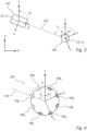
- the target control unit 214 may obtain information regarding an orientation ⁇ of the target 100 relative to the surveying instrument 120 based on at least a measurement received from the sensor unit 216.
- the orientation ⁇ of the target 100 relative to the surveying instrument is illustrated as an angle between the sighting axis 130 and a reference direction y t of the target reference frame ( x t , y t ).
- An instrument control unit may for example determine the orientation A Z i , based on measurements received from at least one sensor of the surveying instrument 120.
- the surveying instrument may comprise an orientation sensor, such as an IMU, a compass, or an angular measurement unit.
- the external sender may comprise a Global Navigation Satellite System (GNSS), as illustrated by the plurality of satellites 10 in Figure 1 .
- GNSS Global Navigation Satellite System
- the control unit 214 may receive the position input via the GNSS receiver 102 illustrated in Figures 1 and 2 .
Landscapes
- Physics & Mathematics (AREA)
- Engineering & Computer Science (AREA)
- General Physics & Mathematics (AREA)
- Radar, Positioning & Navigation (AREA)
- Remote Sensing (AREA)
- Measurement Of Optical Distance (AREA)
Claims (12)
- Ziel (100) zur Verwendung in Vermessungsanwendungen, wobei das Ziel aufweist:mehrere Lichtquellen (106), welche um eine Längsachse (A) eines Basiselements (108) des Ziels herum angeordnet sind und zum radialen Aussenden von Licht konfiguriert sind;eine Sensoreinheit (216); undeine Steuereinheit (214), konfiguriert zum:Erhalten von Informationen über eine Orientierung (α) des Ziels in Bezug auf ein Vermessungsinstrument (120), welches auf das Ziel gerichtet ist, basierend auf zumindest einer Messung, die von der Sensoreinheit empfangen wird;Identifizieren, basierend auf den erhaltenen Informationen über die Orientierung des Ziels in Bezug auf das Vermessungsinstrument, einer ersten Teilgruppe (106c bis 106e) der mehreren Lichtquellen, welche so eingerichtet ist, dass sie Licht in Richtung des Vermessungsinstruments ausgesendet, und einer zweiten Teilgruppe (106a, 106b, 106f bis 106h) der mehreren Lichtquellen, welche so eingerichtet ist, dass sie Licht von dem Vermessungsinstrument weg ausgesendet; undSteuern der mehreren Lichtquellen derart, dass die erste Teilgruppe von Lichtquellen Licht mit einer höheren Intensität ausgesendet als die zweite Teilgruppe von Lichtquellen.
- Verfahren zum Betreiben eines Ziels zur Verwendung in Vermessungsanwendungen, wobei das Ziel mehrere Lichtquellen, welche um eine Längsachse eines Basiselements des Ziels herum angeordnet sind und zum radialen Aussenden von Licht konfiguriert sind, wobei das Verfahren umfasst:Erhalten von Informationen über eine Orientierung (α) des Ziels in Bezug auf ein Vermessungsinstrument (120), welches auf das Ziel gerichtet ist, basierend auf zumindest einer Messung, die von einer Sensoreinheit empfangen wird;Identifizieren, basierend auf den erhaltenen Informationen über die Orientierung des Ziels in Bezug auf das Vermessungsinstrument, einer ersten Teilgruppe der mehreren Lichtquellen, welche so eingerichtet ist, dass sie Licht in Richtung des Vermessungsinstruments ausgesendet, und einer zweiten Teilgruppe der mehreren Lichtquellen, welche so eingerichtet ist, dass sie Licht von dem Vermessungsinstrument weg ausgesendet; undSteuern der mehreren Lichtquellen derart, dass die erste Teilgruppe von Lichtquellen Licht mit einer höheren Intensität ausgesendet als die zweite Teilgruppe von Lichtquellen.
- Ziel nach Anspruch 1 oder Verfahren nach Anspruch 2, wobei:die Sensoreinheit mehrere Sensoren aufweist, welche um die Längsachse des Basiselements des Ziels herum verteilt sind und zum Erfassen eines Signals konfiguriert sind, das von dem Vermessungsinstrument ausgesendet wird; unddie Informationen über die Orientierung des Ziels in Bezug auf das Vermessungsinstrument erhalten werden durch:Erhalten einer Erfassung eines Signals, das von dem Vermessungsinstrument in Richtung des Ziels ausgesendet wird, von den mehreren Sensoren; undBestimmen der Orientierung des Ziels in Bezug auf das Vermessungsinstrument basierend auf einer relativen Signalstärke des Signals, das von den mehreren Sensoren erfasst wird.
- Ziel nach einem der Ansprüche 1 oder 3 oder Verfahren nach einem der Ansprüche 2 oder 3, wobei:die Sensoreinheit mindestens einen bildgebenden Sensor aufweist, welcher zum Erhalten mindestens eines Bildes einer Umgebung des Ziels konfiguriert ist; unddie Informationen über die Orientierung des Ziels in Bezug auf das Vermessungsinstrument erhalten werden durch:Erhalten mindestens eines Bildes einer Umgebung des Ziels von dem mindestens einen bildgebenden Sensor;Identifizieren eines Vermessungsinstruments in dem erhaltenen Bild; undBestimmen der Orientierung des Ziels in Bezug auf das Vermessungsinstrument basierend auf einer Position des identifizierten Vermessungsinstruments in dem erhaltenen Bild.
- Ziel nach einem der Ansprüche 1 oder 3 bis 4 oder Verfahren nach einem der Ansprüche 2 bis 4, wobei die Informationen über die Orientierung des Ziels in Bezug auf das Vermessungsinstrument erhalten werden durch:Empfangen einer Eingabe von dem Vermessungsinstrument (120), welche eine Vermessungsinstrumentorientierung (Ai z ) in einem gemeinsamen Referenzrahmen (X, Y) anzeigt;Bestimmen einer Zielorientierung (At z ) in dem gemeinsamen Referenzrahmen basierend auf Messungen, die von der Sensoreinheit empfangen werden; undBestimmen der Orientierung des Ziels in Bezug auf das Vermessungsinstrument basierend auf der empfangenen Eingabe und der bestimmten Zielorientierung in dem gemeinsamen Referenzrahmen.
- Ziel oder Verfahren nach Anspruch 5, wobei:die Sensoreinheit einen Kompass aufweist;der gemeinsame Referenzrahmen ein globaler Referenzrahmen ist; unddie Bestimmung der Zielorientierung in dem gemeinsamen Referenzrahmen umfasst:Empfangen einer Messung von dem Kompass; undBestimmen der Zielorientierung in dem gemeinsamen Referenzrahmen basierend auf der Messung von dem Kompass.
- Ziel oder Verfahren nach Anspruch 5 oder 6, wobei:die Sensoreinheit eine Trägheitsmesseinheit, Inertial Measurement Unit, IMU, aufweist; unddie Bestimmung der Zielorientierung in dem gemeinsamen Referenzrahmen umfasst:Bestimmen einer ersten Positionsspur (430) des Ziels in einem Zielreferenzrahmen basierend auf Messungen von der IMU;Erhalten einer zweiten Positionsspur (532) des Ziels in dem gemeinsamen Referenzrahmen basierend auf einer Positionseingabe, die von einem externen Sender empfangen wird; undBestimmen der Zielorientierung in dem gemeinsamen Referenzrahmen durch In-Ausrichtung-Bringen der ersten Positionsspur und der zweiten Positionsspur.
- Ziel nach einem der Ansprüche 1 oder 3 bis 7 oder Verfahren nach einem der Ansprüche 2 bis 7, wobei:
die Informationen über eine Orientierung des Ziels in Bezug auf das Vermessungsinstrument erhalten werden durch:Empfangen einer Position (Xi, Yi ) des Vermessungsinstruments in dem gemeinsamen Referenzrahmen von dem Vermessungsinstrument;Erhalten einer Position (Xt, Yt ) des Ziels in dem gemeinsamen Referenzrahmen basierend auf einer Positionseingabe, die von einem externen Sender empfangen wird;Bestimmen einer Zielorientierung (At z ) in dem gemeinsamen Referenzrahmen basierend auf Messungen, die von der Sensoreinheit empfangen werden; undBestimmen der Orientierung des Ziels in Bezug auf das Vermessungsinstrument basierend auf der Position des Vermessungsinstruments, der Position des Ziels und der Zielorientierung in dem gemeinsamen Referenzrahmen. - Ziel oder Verfahren nach Anspruch 7 oder 8, wobei:die Sensoreinheit einen Global-Navigation-Satellite-System-Empfänger, GNSS-Empfänger (102), aufweist; undwobei die Positionseingabe, die von einem externen Sender empfangen wird, eine Zielpositionseingabe umfasst, die über den GNSS-Empfänger empfangen wird.
- Ziel oder Verfahren nach einem der Ansprüche 7 bis 9, wobei:
die Positionseingabe, die von einem externen Sender empfangen wird, eine Zielpositionseingabe umfasst, die von dem Vermessungsinstrument empfangen wird. - Ziel nach einem der Ansprüche 1 oder 3 bis 10 oder Verfahren nach einem der Ansprüche 2 bis 10, wobei die Steuerung der mehreren Lichtquellen Steuern der zweiten Teilgruppe von Lichtquellen derart umfasst, dass sie ausgeschaltet sind.
- Ziel nach einem der Ansprüche 1 oder 3 bis 11 oder Verfahren nach einem der Ansprüche 2 bis 11, wobei die mehreren Lichtquellen mindestens sechs Lichtquellen umfassen, welche symmetrisch um die Längsachse des Basiselements herum angeordnet sind.
Priority Applications (2)
| Application Number | Priority Date | Filing Date | Title |
|---|---|---|---|
| EP23161296.1A EP4428490B1 (de) | 2023-03-10 | 2023-03-10 | Vermessungsziel und verfahren mit lichtsektorleistungsoptimierung |
| US18/542,415 US20240302166A1 (en) | 2023-03-10 | 2023-12-15 | Surveying target and method with light sector power optimization |
Applications Claiming Priority (1)
| Application Number | Priority Date | Filing Date | Title |
|---|---|---|---|
| EP23161296.1A EP4428490B1 (de) | 2023-03-10 | 2023-03-10 | Vermessungsziel und verfahren mit lichtsektorleistungsoptimierung |
Publications (2)
| Publication Number | Publication Date |
|---|---|
| EP4428490A1 EP4428490A1 (de) | 2024-09-11 |
| EP4428490B1 true EP4428490B1 (de) | 2025-07-02 |
Family
ID=85571243
Family Applications (1)
| Application Number | Title | Priority Date | Filing Date |
|---|---|---|---|
| EP23161296.1A Active EP4428490B1 (de) | 2023-03-10 | 2023-03-10 | Vermessungsziel und verfahren mit lichtsektorleistungsoptimierung |
Country Status (2)
| Country | Link |
|---|---|
| US (1) | US20240302166A1 (de) |
| EP (1) | EP4428490B1 (de) |
Family Cites Families (2)
| Publication number | Priority date | Publication date | Assignee | Title |
|---|---|---|---|---|
| US8040528B2 (en) * | 2007-05-30 | 2011-10-18 | Trimble Ab | Method for target tracking, and associated target |
| JP6316568B2 (ja) * | 2013-10-31 | 2018-04-25 | 株式会社トプコン | 測量システム |
-
2023
- 2023-03-10 EP EP23161296.1A patent/EP4428490B1/de active Active
- 2023-12-15 US US18/542,415 patent/US20240302166A1/en active Pending
Also Published As
| Publication number | Publication date |
|---|---|
| EP4428490A1 (de) | 2024-09-11 |
| US20240302166A1 (en) | 2024-09-12 |
Similar Documents
| Publication | Publication Date | Title |
|---|---|---|
| US11486704B2 (en) | Intelligent positioning module | |
| CN114585875B (zh) | 计量系统 | |
| US7728963B2 (en) | Method for determining the orientation of an orientation indicator | |
| CN100580373C (zh) | 用于确定手持测量仪的空间位置的方法和系统 | |
| JP7378545B2 (ja) | ターゲット装置および測量方法 | |
| US20150116693A1 (en) | Three-Dimensional Measuring Method And Surveying System | |
| CN101095061B (zh) | 用于确定至少一个对象的姿态信息项的方法和旋转激光器 | |
| US20090115655A1 (en) | Managed traverse system and method to acquire accurate survey data in absence of precise GPS data | |
| JP2001509851A (ja) | 作業部の位置を決定するための装置と方法 | |
| CN103477187A (zh) | 用于确定新点的测量系统和方法 | |
| CN104101334A (zh) | 点云的大地测量参照 | |
| CN101529203A (zh) | 使用gps和激光基准的导航系统 | |
| JP2001509852A (ja) | 作業部の位置を決定するための装置と方法 | |
| US12111156B2 (en) | Target device and surveying system | |
| US20260002781A1 (en) | Surveying target and method with distance power optimization | |
| US12209862B2 (en) | Automatic, stationing of a geodetic survey instrument based on reference marker database | |
| US20230288201A1 (en) | Reference free calibration method for a point cloud measuring module combined with a geodetic single point measurement unit | |
| EP4428490B1 (de) | Vermessungsziel und verfahren mit lichtsektorleistungsoptimierung | |
| US20210080257A1 (en) | Survey pole with indicia for automatic tracking | |
| JP2000234929A (ja) | 中継式自動位置姿勢計測システム | |
| US7982685B2 (en) | Radome | |
| US20210199784A1 (en) | Calibrating a total station | |
| US20250146817A1 (en) | Integrated gnss and optical system | |
| JP2019113491A (ja) | ターゲット装置、測量方法、測量装置および測量用プログラム | |
| ITMI20081879A1 (it) | Metodo e dispositivo per la rilevazione della posizione geografica di unobiettivo |
Legal Events
| Date | Code | Title | Description |
|---|---|---|---|
| PUAI | Public reference made under article 153(3) epc to a published international application that has entered the european phase |
Free format text: ORIGINAL CODE: 0009012 |
|
| STAA | Information on the status of an ep patent application or granted ep patent |
Free format text: STATUS: THE APPLICATION HAS BEEN PUBLISHED |
|
| AK | Designated contracting states |
Kind code of ref document: A1 Designated state(s): AL AT BE BG CH CY CZ DE DK EE ES FI FR GB GR HR HU IE IS IT LI LT LU LV MC ME MK MT NL NO PL PT RO RS SE SI SK SM TR |
|
| STAA | Information on the status of an ep patent application or granted ep patent |
Free format text: STATUS: REQUEST FOR EXAMINATION WAS MADE |
|
| 17P | Request for examination filed |
Effective date: 20241003 |
|
| RBV | Designated contracting states (corrected) |
Designated state(s): AL AT BE BG CH CY CZ DE DK EE ES FI FR GB GR HR HU IE IS IT LI LT LU LV MC ME MK MT NL NO PL PT RO RS SE SI SK SM TR |
|
| GRAP | Despatch of communication of intention to grant a patent |
Free format text: ORIGINAL CODE: EPIDOSNIGR1 |
|
| STAA | Information on the status of an ep patent application or granted ep patent |
Free format text: STATUS: GRANT OF PATENT IS INTENDED |
|
| RIC1 | Information provided on ipc code assigned before grant |
Ipc: G01C 15/00 20060101AFI20250115BHEP |
|
| INTG | Intention to grant announced |
Effective date: 20250131 |
|
| GRAS | Grant fee paid |
Free format text: ORIGINAL CODE: EPIDOSNIGR3 |
|
| GRAA | (expected) grant |
Free format text: ORIGINAL CODE: 0009210 |
|
| STAA | Information on the status of an ep patent application or granted ep patent |
Free format text: STATUS: THE PATENT HAS BEEN GRANTED |
|
| AK | Designated contracting states |
Kind code of ref document: B1 Designated state(s): AL AT BE BG CH CY CZ DE DK EE ES FI FR GB GR HR HU IE IS IT LI LT LU LV MC ME MK MT NL NO PL PT RO RS SE SI SK SM TR |
|
| REG | Reference to a national code |
Ref country code: GB Ref legal event code: FG4D |
|
| REG | Reference to a national code |
Ref country code: CH Ref legal event code: EP |
|
| REG | Reference to a national code |
Ref country code: DE Ref legal event code: R096 Ref document number: 602023004392 Country of ref document: DE |
|
| REG | Reference to a national code |
Ref country code: IE Ref legal event code: FG4D |
|
| REG | Reference to a national code |
Ref country code: NL Ref legal event code: MP Effective date: 20250702 |
|
| PG25 | Lapsed in a contracting state [announced via postgrant information from national office to epo] |
Ref country code: PT Free format text: LAPSE BECAUSE OF FAILURE TO SUBMIT A TRANSLATION OF THE DESCRIPTION OR TO PAY THE FEE WITHIN THE PRESCRIBED TIME-LIMIT Effective date: 20251103 |
|
| PG25 | Lapsed in a contracting state [announced via postgrant information from national office to epo] |
Ref country code: NL Free format text: LAPSE BECAUSE OF FAILURE TO SUBMIT A TRANSLATION OF THE DESCRIPTION OR TO PAY THE FEE WITHIN THE PRESCRIBED TIME-LIMIT Effective date: 20250702 |
|
| REG | Reference to a national code |
Ref country code: AT Ref legal event code: MK05 Ref document number: 1809664 Country of ref document: AT Kind code of ref document: T Effective date: 20250702 |
|
| PG25 | Lapsed in a contracting state [announced via postgrant information from national office to epo] |
Ref country code: IS Free format text: LAPSE BECAUSE OF FAILURE TO SUBMIT A TRANSLATION OF THE DESCRIPTION OR TO PAY THE FEE WITHIN THE PRESCRIBED TIME-LIMIT Effective date: 20251102 |
|
| PG25 | Lapsed in a contracting state [announced via postgrant information from national office to epo] |
Ref country code: NO Free format text: LAPSE BECAUSE OF FAILURE TO SUBMIT A TRANSLATION OF THE DESCRIPTION OR TO PAY THE FEE WITHIN THE PRESCRIBED TIME-LIMIT Effective date: 20251002 |
|
| REG | Reference to a national code |
Ref country code: LT Ref legal event code: MG9D |
|
| PG25 | Lapsed in a contracting state [announced via postgrant information from national office to epo] |
Ref country code: AT Free format text: LAPSE BECAUSE OF FAILURE TO SUBMIT A TRANSLATION OF THE DESCRIPTION OR TO PAY THE FEE WITHIN THE PRESCRIBED TIME-LIMIT Effective date: 20250702 |
|
| PG25 | Lapsed in a contracting state [announced via postgrant information from national office to epo] |
Ref country code: FI Free format text: LAPSE BECAUSE OF FAILURE TO SUBMIT A TRANSLATION OF THE DESCRIPTION OR TO PAY THE FEE WITHIN THE PRESCRIBED TIME-LIMIT Effective date: 20250702 |
|
| PG25 | Lapsed in a contracting state [announced via postgrant information from national office to epo] |
Ref country code: HR Free format text: LAPSE BECAUSE OF FAILURE TO SUBMIT A TRANSLATION OF THE DESCRIPTION OR TO PAY THE FEE WITHIN THE PRESCRIBED TIME-LIMIT Effective date: 20250702 |
|
| PG25 | Lapsed in a contracting state [announced via postgrant information from national office to epo] |
Ref country code: GR Free format text: LAPSE BECAUSE OF FAILURE TO SUBMIT A TRANSLATION OF THE DESCRIPTION OR TO PAY THE FEE WITHIN THE PRESCRIBED TIME-LIMIT Effective date: 20251003 |
|
| PG25 | Lapsed in a contracting state [announced via postgrant information from national office to epo] |
Ref country code: CZ Free format text: LAPSE BECAUSE OF FAILURE TO SUBMIT A TRANSLATION OF THE DESCRIPTION OR TO PAY THE FEE WITHIN THE PRESCRIBED TIME-LIMIT Effective date: 20250702 Ref country code: SE Free format text: LAPSE BECAUSE OF FAILURE TO SUBMIT A TRANSLATION OF THE DESCRIPTION OR TO PAY THE FEE WITHIN THE PRESCRIBED TIME-LIMIT Effective date: 20250702 |
|
| PG25 | Lapsed in a contracting state [announced via postgrant information from national office to epo] |
Ref country code: LV Free format text: LAPSE BECAUSE OF FAILURE TO SUBMIT A TRANSLATION OF THE DESCRIPTION OR TO PAY THE FEE WITHIN THE PRESCRIBED TIME-LIMIT Effective date: 20250702 |
|
| PG25 | Lapsed in a contracting state [announced via postgrant information from national office to epo] |
Ref country code: BG Free format text: LAPSE BECAUSE OF FAILURE TO SUBMIT A TRANSLATION OF THE DESCRIPTION OR TO PAY THE FEE WITHIN THE PRESCRIBED TIME-LIMIT Effective date: 20250702 Ref country code: PL Free format text: LAPSE BECAUSE OF FAILURE TO SUBMIT A TRANSLATION OF THE DESCRIPTION OR TO PAY THE FEE WITHIN THE PRESCRIBED TIME-LIMIT Effective date: 20250702 |
|
| PG25 | Lapsed in a contracting state [announced via postgrant information from national office to epo] |
Ref country code: RS Free format text: LAPSE BECAUSE OF FAILURE TO SUBMIT A TRANSLATION OF THE DESCRIPTION OR TO PAY THE FEE WITHIN THE PRESCRIBED TIME-LIMIT Effective date: 20251002 |
|
| PG25 | Lapsed in a contracting state [announced via postgrant information from national office to epo] |
Ref country code: ES Free format text: LAPSE BECAUSE OF FAILURE TO SUBMIT A TRANSLATION OF THE DESCRIPTION OR TO PAY THE FEE WITHIN THE PRESCRIBED TIME-LIMIT Effective date: 20250702 |
|
| PG25 | Lapsed in a contracting state [announced via postgrant information from national office to epo] |
Ref country code: SM Free format text: LAPSE BECAUSE OF FAILURE TO SUBMIT A TRANSLATION OF THE DESCRIPTION OR TO PAY THE FEE WITHIN THE PRESCRIBED TIME-LIMIT Effective date: 20250702 |
|
| PG25 | Lapsed in a contracting state [announced via postgrant information from national office to epo] |
Ref country code: DK Free format text: LAPSE BECAUSE OF FAILURE TO SUBMIT A TRANSLATION OF THE DESCRIPTION OR TO PAY THE FEE WITHIN THE PRESCRIBED TIME-LIMIT Effective date: 20250702 |
|
| PGFP | Annual fee paid to national office [announced via postgrant information from national office to epo] |
Ref country code: DE Payment date: 20260320 Year of fee payment: 4 |
|
| PG25 | Lapsed in a contracting state [announced via postgrant information from national office to epo] |
Ref country code: IT Free format text: LAPSE BECAUSE OF FAILURE TO SUBMIT A TRANSLATION OF THE DESCRIPTION OR TO PAY THE FEE WITHIN THE PRESCRIBED TIME-LIMIT Effective date: 20250702 |
|
| PGFP | Annual fee paid to national office [announced via postgrant information from national office to epo] |
Ref country code: FR Payment date: 20260323 Year of fee payment: 4 |