EP4428445A1 - Fume extraction device, combination appliance and method for operating a fume extraction device or a combination appliance - Google Patents
Fume extraction device, combination appliance and method for operating a fume extraction device or a combination appliance Download PDFInfo
- Publication number
- EP4428445A1 EP4428445A1 EP23160227.7A EP23160227A EP4428445A1 EP 4428445 A1 EP4428445 A1 EP 4428445A1 EP 23160227 A EP23160227 A EP 23160227A EP 4428445 A1 EP4428445 A1 EP 4428445A1
- Authority
- EP
- European Patent Office
- Prior art keywords
- extraction device
- fume extraction
- cooking
- cover element
- suction opening
- Prior art date
- Legal status (The legal status is an assumption and is not a legal conclusion. Google has not performed a legal analysis and makes no representation as to the accuracy of the status listed.)
- Pending
Links
Images




Classifications
-
- F—MECHANICAL ENGINEERING; LIGHTING; HEATING; WEAPONS; BLASTING
- F24—HEATING; RANGES; VENTILATING
- F24C—DOMESTIC STOVES OR RANGES ; DETAILS OF DOMESTIC STOVES OR RANGES, OF GENERAL APPLICATION
- F24C15/00—Details
- F24C15/20—Removing cooking fumes
- F24C15/2064—Removing cooking fumes illumination for cooking hood
-
- F—MECHANICAL ENGINEERING; LIGHTING; HEATING; WEAPONS; BLASTING
- F24—HEATING; RANGES; VENTILATING
- F24C—DOMESTIC STOVES OR RANGES ; DETAILS OF DOMESTIC STOVES OR RANGES, OF GENERAL APPLICATION
- F24C15/00—Details
- F24C15/20—Removing cooking fumes
- F24C15/2042—Devices for removing cooking fumes structurally associated with a cooking range e.g. downdraft
Definitions
- the present invention relates to a downdraft fume extraction device according to claim 1.
- the present invention relates further to a combination appliance comprising a cooking hob and a fume extraction device according to claim 9 and to a method for operating a fume extraction device or a combination appliance according to claim 12.
- cooking hobs comprise cooking zones for placement of cookware receiving the food to be cooked.
- the cooking zones are generally arranged on a cooktop, in particular a glass ceramic cooktop, which forms an upper wall of the cooking hob.
- cooking fumes are generated, which are distributed over the cooking area.
- an extraction hood above the cooking area for an aspiration of these fumes.
- downdraft fume extraction devices which are arranged or arrangeable below a worktop of a kitchen furniture, particularly in a side-by-side arrangement with a cooking hob.
- cooking hobs known, in which such a cooking fumes extraction functionality is integrated.
- such kind of a combination appliance comprises a cooking hob and an integrated downdraft extraction device with an extraction opening in the cooktop of the cooking hob. With this combination of a cooking hob and an extraction device, a compact solution is provided. Extraction hood or extraction device can be operated in parallel to the cooking hob, thereby sucking in those cooking fumes in order to filter out particles and tiny droplets and/or to blow the cooking fumes to the outside of the building.
- the document EP 3 951 267 A1 discloses a combination appliance comprising a cooking hob and an extraction device, in which air is sucked through a recess of a support surface, and which comprises a lid for covering the recess.
- An illumination device comprising light sources is arranged in the area of the recess and is configured to provide information about operating parameters of the combination appliance to the user by changing one or more light parameters over time.
- the object is achieved for a fume extraction device, more specifically a downdraft fume extraction device, according to a first aspect of the present invention, according to the preamble of claim 1 by the features of the characterizing part of claim 1.
- a fume extraction device which is arranged or arrangeable below a worktop.
- the fume extraction device is particularly designed using the downdraft principle with sucking air in downwards direction.
- the fume extraction device in general comprises a fan for sucking air from the area above the cooking hob through a suction opening of the fume extraction device, a cover element, which is arranged at the suction opening, and at least one light source.
- the cover element is preferably a flat and/or plate-shaped cover element and/or is configured to partially or completely cover the suction opening.
- the at least one light source is arranged in the area of the suction opening. Additionally or alternatively, the at least one light source is arranged at or on the cover element.
- the at least one light source comprises a display means configured to provide visual information to a user of the fume extraction device.
- the at least one light source is configured to display an operational parameter and/or status information of the fume extraction device. Additionally, or alternatively, information about status or parameters of a cooking process may particularly be displayable.
- a preferred embodiment of the fume extraction device also includes at least one filter element for removing particles and/or odours from the air sucked in, which air may comprise fumes from a cooking process, so that the at least one filter element particularly provides a grease and/or odour filter function.
- the cover element is moveable from a first position to at least a second position
- the display means is arranged at or on the moveable cover element and is configured to display the visual information both in the first position and in the at least second position of the cover element.
- the first position and the at least a second position particularly differ from each other in a horizontal displacement and/or in a vertical displacement and/or in an angular alignment.
- the cover element and/or the display means is or are designed in such a manner as to provide the visual information wherever the cover element is currently positioned, which position may depend on a specific operational mode and/or on a specific process step.
- said first position and at least a second position may also mean that the cover element can be positioned arbitrarily and electrical connection is possible on a continuous path.
- the fume extraction device may be assigned to or included in a cooking hood.
- the at least one filter element may also be adapted for a filtering of other substances or compounds of specifically cooking fumes, such as vapours or volatile organic compounds.
- the at least one filter element may be arranged or arrangeable in a fixed filter holder, but preferably it is supported by a filter carrier, which advantageously is removable from its operative position, particularly removable from the fume extraction unit.
- the extraction device may further include an outlet opening for exhaust air, which may be exhausted into the ambient air.
- the fan may be provided for sucking air from the area above the cooking hob through the suction opening of the cover plate or worktop and for conveying it through an air duct of the extraction device comprising the at least one filter element to the outlet opening.
- the filter element may be arranged or arrangeable upstream of the fan and downstream of the suction opening.
- the object is achieved for a fume extraction device, more specifically a downdraft fume extraction device, according to a second aspect of the present invention, according to the preamble of claim 2 by the features of the characterizing part of claim 2.
- a fume extraction device which is arranged or arrangeable below a worktop.
- the fume extraction device is particularly designed using the downdraft principle with sucking air in downwards direction.
- the fume extraction device in general comprises a fan for sucking air from the area above the cooking hob through a suction opening of the fume extraction device, a cover element, which is arranged at the suction opening, and at least one light source.
- the cover element is preferably a flat and/or plate-shaped cover element and/or is configured to partially or completely cover the suction opening.
- the at least one light source is arranged in the area of the suction opening. Additionally or alternatively, the at least one light source is arranged at or on the cover element.
- the at least one light source comprises a display means configured to provide visual information to a user of the fume extraction device.
- the at least one light source is configured to display an operational parameter and/or status information of the fume extraction device. Additionally, or alternatively, information about status or parameters of a cooking process may particularly be displayable.
- a preferred embodiment of the fume extraction device also includes at least one filter element for removing particles and/or odours from the air sucked in, which air may comprise fumes from a cooking process, so that the at least one filter element particularly provides a grease and/or odour filter function.
- the fume extraction device according to the second aspect of the invention may be a specific design of the fume extraction device according to the first aspect of the invention.
- the display means comprises at least one display element for a display of alphanumeric and/or symbol characters.
- the display element preferably includes at least one of an LED display, an OLED display, an LCD display, a TFT display, and a seven-segment display.
- Such types of characters particularly have an increased explanatory power compared to any kind of light signals, possibly differentiated by intensity, colouring and/or blinking frequency.
- the cover element may be a grid or any kind of covering means with full-surface or part surface extension, particularly at least temporarily fully or partly covering the suction opening.
- the cover element may be designed as a fixed and/or immovable element, or it may be configured to cover only sections of the suction opening, but changing sections at different times.
- the fume extraction device may be assigned to or included in a cooking hood.
- the at least one filter element may also be adapted for a filtering of other substances or compounds of specifically cooking fumes, such as vapours or volatile organic compounds.
- the at least one filter element may be arranged or arrangeable in a fixed filter holder, but preferably it is supported by a filter carrier, which advantageously is removable from its operative position, particularly removable from the fume extraction unit.
- the extraction device may further include an outlet opening for exhaust air, which may be exhausted into the ambient air.
- the fan may be provided for sucking air from the area above the cooking hob through the suction opening of the cover plate or worktop and for conveying it through an air duct of the extraction device comprising the at least one filter element to the outlet opening.
- the filter element may be arranged or arrangeable upstream of the fan and downstream of the suction opening.
- the cover element may be electrically connected to a control unit of the fume extraction device, so that an operative control may be centrally performable. Additionally or alternatively, at least a part of a control functionality may be outsourced to a unit arranged on the cover element.
- the connection between the control unit of the extraction device and the light source on the cover element, specifically the display means, is particularly established via an electrical contact, in particular at least one contact element or contact pair. Said electrical contact may be arranged in the area, more particularly at a rim or border, surrounding the suction opening.
- the cover element is preferably removably arranged at the suction opening, more preferably removably arranged within the area of the suction opening, and the electrical connection is configured to be disconnected and reconnected.
- the electrical connection is configured to be interrupted at the electrical contact, in particular by disconnecting the at least one contact pair.
- the electrical connection in particular the electrical contact, comprises a plurality of contact points discretely arranged in a row arranged in the area, which surrounds the suction opening. Said surrounding area is more specifically a rim or border of or around the suction opening.
- the electrical connection may be established by a sliding contact, which may provide a continuous maintaining of the electrical connection between display means and control unit, whichever position may be the current one for the cover element.
- a particular embodiment is characterized in that at least one moveable contact pin and at least one fixed contact rail are included.
- the electrical connection is a multicore connection including at least two electrical wires and comprises at least a first contact pair and a second contact pair.
- the first and second contact pairs may be arranged at the same side of the cover element.
- the first and second contact pairs may be arranged at different sides, preferably at opposite sides, of the cover element, which may particularly be relevant in the case of a rectangular cover element.
- an incorrect placement, e. g. an upside-down arrangement, of the cover element may be prevented by a protection means for misplacement.
- the at least one light source comprises at least one illuminable lateral edge, preferably an illuminable rim, which particularly comprises or is covered with an LED array, a plurality of single LED and/or an OLED light strip.
- the at least one illuminable lateral edge in particular the illuminable rim, is arranged at the edge of the suction opening and/or at the circumferential edge of the cover element.
- a combination appliance comprises a cooking hob and a fume extraction device as herein disclosed, particularly as previously described in general or by embodiments.
- the cooking hob comprises a cover plate or worktop, which has an opening or a recess formed therein.
- the cover plate or worktop is in particular a glass plate.
- the fume extraction device is arranged below the cooking hob, in particular below the cover plate or worktop of the cooking hob. Said opening or recess forms the suction opening of the fume extraction device.
- the cooking hob may be of any type including electric or gas cooking hobs.
- an induction cooking hob is a part of the combination appliance.
- the cooking hob may further be an autarkic cooking appliance, particularly integrated in a countertop of kitchen furniture, or it may be part of a stove.
- a top surface of the cover plate or worktop which is accessible to a user of the combination appliance, may be used for putting cookware thereon, specifically in order to perform a cooking process.
- the cooking hob preferably comprises at least one heating element defining a cooking zone on the cover plate or worktop.
- the cover plate or worktop may be of any suitable design or material, but favourably it is made out of glass, notably of glass ceramics.
- the light source specifically the display means
- the display means is configured to display operational parameters and/or status information of the fume extraction device and/or of the cooking hob.
- the display means is preferably configured to display information supporting a user to perform a cooking process, which information is specifically a recipe information or any information related to a proper use of the cooking hob or the fume extraction device.
- At least a section or zone of the display means may be designed to be touch sensitive.
- an input means for the selection of a specific cooking zone on the cover plate or worktop of the cooking hob may be available, preferably next to the specific zone, which not only indicates to the user a dedicated assignment between this particular input means and the related cooking zone, but also allows a simple selection of this cooking zone, e. g. for the selection of a power level, with which the cooking zone shall be operated.
- the at least a section or zone of the display means may be useable for an activation of a function of the fume extraction device. This may include setting a power level or a rotational speed of the fan in order to set a specific suction force, which may depend on the amount of cooking fumes arising from the actual cooking process.
- the fume extraction device may be designed in a way as to steer the suction force to a certain suction direction, i. e. focussed on a fume source. In that case it is favourable to allocate the section or zone of the display means to a specific cooking zone on the cover plate or worktop of the cooking hob for a control of the suction direction.
- a displacement of the cover element may be performable, notably by a specific selection or operation of the at least a section or zone of the display means in order to provide a relevant inlet opening for cooking fumes related to the specific cooking zone.
- the object is also achieved by a method for operating a fume extraction device or a combination appliance, which comprises a cooking hob and an extraction device, according to the preamble of claim 12 by the characterizing part of claim 12.
- a method for operating a fume extraction device or a combination appliance which comprises a cooking hob and a fume extraction device.
- the fume extraction device and/or the combination appliance may be designed as herein disclosed, particularly as previously described in general or by embodiments.
- the fume extraction device or the combination appliance sucks in fumes, in particular cooking fumes, through a suction opening of the fume extraction device.
- a cover element which is preferably flat and/or plate-shaped, is arranged at the suction opening. The cover element preferably partially covers the suction opening at least during at least one process step.
- At least one light source of the fume extraction device or of the combination appliance provides visual information.
- Said light source comprises a display means and is arranged in the area of the suction opening and/or at or on the cover element.
- the visual information provided by the at least one light source of the fume extraction device or of the combination appliance may be about an operational parameter and/or status information of the fume extraction device and/or of the cooking hob. Additionally, or alternatively, information about status or parameters of a cooking process may particularly be displayed.
- the cover element is moveably arranged at the suction opening and the at least one light source, which may be the display means that is arranged at or on the moveable cover element, provides the visual information in the current position in which the cover element is located during the at least one process step. That means that the cover element may be located at any arbitrary position, whichever position is possible and accessible by the cover element, and in each position the display of the visual information is enabled. That way it is possible to display the information that currently shall be provided, without taking care of the actual position of the cover element.
- a method for operating a fume extraction device or a combination appliance which comprises a cooking hob and a fume extraction device, is provided.
- the fume extraction device and/or the combination appliance may be designed as herein disclosed, particularly as previously described in general or by embodiments. According to this method, the fume extraction device or the combination appliance sucks in fumes, in particular cooking fumes, through a suction opening of the fume extraction device. Further, a cover element, which is preferably flat and/or plate-shaped, is arranged at the suction opening. The cover element preferably partially covers the suction opening at least during at least one process step. In the at least one process step at least one light source of the fume extraction device or of the combination appliance provides visual information. Said light source comprises a display means and is arranged in the area of the suction opening and/or at or on the cover element.
- the visual information provided by the at least one light source of the fume extraction device or of the combination appliance may be about an operational parameter and/or status information of the fume extraction device and/or of the cooking hob. Additionally, or alternatively, information about status or parameters of a cooking process may particularly be displayed. According to the present invention, the visual information provided on the cover element comprises at least one alphanumeric and/or symbol characters.
- the cover element may be a grid or any kind of covering means with full-surface or part surface extension, particularly at least temporarily fully or partly covering the suction opening.
- the cover element may be fixed positioned in or at the suction opening and/or immovable at all times, or it may be cover only sections of the suction opening, but changing sections at different times.
- a preferred embodiment of the method according to the fourth aspect or according to the fifth aspect of the present invention is characterized in that the at least one light source comprises a light rim arranged at the edge of the suction opening and/or of the cover element, which at least one light source indicates by means of a specific light presentation method at least one of the following status information or error massages.
- One specific embodiment provides for at least one light source that is activated or triggered or controlled by a user interface input, which is particularly dependent on a selected cooking zone and/or a selected operating mode of the fume extraction device.
- Another specific embodiment which may be an addition or an alternative, provides for at least one light source that is activated or triggered or controlled by an input of a measuring or detection means.
- Said measuring or detection means is in particular a detection means for detection of the current position of cookware on the related cooking zone and/or a sensor for at least one of a humidity level, a temperature level, and a presence or amount of volatile organic compounds, wherein these parameters temperature, humidity and volatile organic compounds, which may cause odours, in general can work as an indication for the current air quality.
- At least one of the methods according to the present invention is characterized in that during at least one process step, the at least one light source visualizes an operation of the fume extraction device as an air purification device.
- a sanitation device preferably performs an air purification and/or a neutralization of microbiological contamination of the treated air.
- Such kind of air treatment may be performed independently from any fume extraction operation.
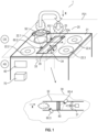
- Fig. 1 illustrates schematically a first example of a combination appliance 1, which comprises a hob 20 and a fume ex-traction device 30.
- the hob 20 comprises a cooktop plate 21 and cooking units 22.1 to 22.4 on a cooking side CS, which represents the area above the cooktop plate 21 accessible to the user of the combination appliance for performing the cooking process.
- the cooktop plate 21 is preferably configured essentially plate-shaped and/or essentially flat.
- the cooktop plate 21 is made, for example, of a glass-ceramic material.
- the orientation of the cooktop plate 21 may be described by a plane P21.
- the plane P21 is preferably a definable or determinable mid-plane or a reference plane of the cooktop plate 21. In the operating status or in an installed status of the combination appliance 1, the cooktop plate 21 is arranged substantially horizontally.
- the cooking units 22.1 to 22.4 are preferably induction cooking units 22.1 to 22.4 each comprising at least an induction coil and a power board (not shown in the figures for reasons of clarity).
- the cooking units 22.1 to 22.4 are configured differently with regard to the principle of generating heat, for example, as heating coils, gas burners or the like.
- a cooking vessel 50 is placed on cooking unit 22.1 in Fig. 1 and cooking unit 22.1 is activated for food preparation thus generating fumes by heating the content of the cooking vessel 50.
- Fumes comprise in particular at least grease and/or odors.
- the cooktop plate 21 further comprises a recess 23 with a recess cross-section 23A or defining a recess cross-section 23A.
- the recess 23 is formed in the cooktop plate 21 of the hob 20.
- the recess cross-section 23A may comprise, according to Figs. 1 and 2 , an essentially rectangular contour in a view, preferably in a top view.
- the second example according to Fig. 3 shows that the recess cross-section 23A may alternatively comprise an essentially circular or an oval contour in a view, preferably in a top view.
- the recess cross-section 23A forms at least partially or at least in sections the flow cross-section of the fumes at the entrance into fume extraction device 30, hence forming a suction opening for the fume extraction device 30, which will be described in further detail in the following.
- the fume extraction device 30 comprises a flow channel 32 for guiding, preferably extracting, fumes from the cooking side CS of the hob 20 through the recess 23 in the direction X of a blower unit 31 of the fume extraction device 30, which includes a fan wheel and a drive element such as an electric motor for driving the fan wheel in order to generate an extraction effect.
- the blower unit 31 is arranged below the cooktop plate 21 on the apparatus side AS, which is opposite to the cooking side CS with reference to the cooktop plate 21, preferably the plane P21 related to the cooktop plate 21.
- An inlet cavity 33 is arranged in or formed at the recess 23, preferably at the apparatus side AS.
- the inlet cavity 33 may be designed box-shaped.
- the inlet cavity 33 is in flow connection with the flow channel 32 and comprises or is connected to a cover element 35 for covering at least partially the recess 23 and preferably at least partially the recess cross-section 23A thus influencing a (resulting) flow cross-section of the fumes to be extracted from the hob 20.
- the inlet cavity 33 further comprises a drive unit 34.
- the drive unit 34 may be configured as an electromechanical drive unit or as a pneumatic drive unit or as a hydraulic drive unit or a combination thereof, which will be described in further detail below.
- the cover element 35 is configured for actuation by the drive unit 34 in order to at least partially cover the recess cross-section 23A on the basis of at least one parameter relating to at least one of the cooking units 22.1 to 22.4.
- the cover element 35 is a movable and/or dynamic element being driven, i.e., actuated by the drive unit 34 in order to further optimize the extraction effect of the fume extraction device 30.
- the cover element 35 may be configured essentially plate-shaped and/or flat. In other words, the cover element 35 may be formed as an essentially flat shield or an essentially flat lid.
- the combination appliance 1 further comprises several or a plurality of sensor units 60.1 to 60.4. At least one sensor unit 60.1, 60.2 is preferably arranged and/or integrated in the cooktop plate 21. It is possible that a further at least one sensor unit 60.3, 60.4 is arranged in the flow channel 32 upstream the blower unit 31.
- a filter unit 80 of the fume extraction device 30, comprising at least one grease filter element and/or at least one odor filter element, may be arranged in the flow channel 32 between a third sensor unit 60.3 and a fourth sensor unit 60.4.
- a sensor unit 60.1 to 60.4 preferably comprises at least one of the following: temperature sensor, humidity sensor and/or a (total) volatile compound (TVOC/VOC) sensor, at least the latter one being configured to detect air quality at least in the region between the recess 23 and thus the inlet cavity 33 and the first cooking unit 22.1 and/or second cooking unit 22.2.
- the at least one parameter may relate to at least one of the cooking units 22.1 to 22.4.
- cover element 35 As illustrated in Fig. 1 , it is configured to be actuated translationally by the drive unit 34. In addition, or alternatively, the drive unit 34 may be configured to actuate the cover element 35 rotationally.
- the translational movement options i.e., in this case directions of possible displacement of the cover element 35, are indicated in Fig. 1 in the area of the cover element 35 by the double arrow.
- the cover element 35 can be actuated by the drive unit 34 either in the direction of the cooking units 22.1 and 22.2 or in the direction of the cooking units 22.3 and 22.4 and thus changing the size of the recess cross-section 23A and/or the position or location of the (effective) flow cross-section of the fumes to be extracted from the hob 20.
- the combination appliance 1 further comprises a user interface unit 40 for a user of the combination appliance 1 to operate at least one of the cooking units 22.1 to 22.4 and/or the blower unit 31 of the fume extraction device 30.
- the combination appliance 1 comprises a control unit 70 that may be preferably an electronic control unit 70.
- the control unit 70 may be a separate component of the combination appliance 1 or may be integrated, for example, in the user interface unit 40.
- the control unit 70 can control at least one of the cooking units 22.1 to 22.4, i.e., preferably power boards of the cooking units 22.1 to 22.4 in the present example of the combination appliance 1 and/or the blower unit 31 of the fume extraction device 30 of the combination appliance 1.
- the control unit 70 may be configured for controlling the drive unit 34 dependent on the at least one parameter, inter alia preferably detected by at least one sensor unit 60.1 to 60.4 of the combination appliance 1.
- the control unit 70 may be connected at least to the cooking units 22.1 to 22.4, the sensor units 60.1 to 60.4, the blower unit 31 and the drive unit 34 via a data bus system (not shown in the figures for reasons of clarity) for signal communication and may control these components in a closed loop configuration.
- the control unit 70 may control the blower unit 31 and/or the drive unit 34 dependent on the operating status of the cooking unit 22.1 and/or a parameter being in relation to the cooking unit 22.1 such as temperature of the cooking unit 22.1 and/or temperature of the content of the cooking vessel 50, air quality and/or air composition at least between the recess 23 and the cooking unit 22.1.
- Controlling the blower unit 31 may comprise adjusting the rotational speed of the fan wheel of the blower unit 31 via the drive element, i.e., the electric motor, of the fan wheel.
- controlling the drive unit 34 may comprise or result in actuating the cover element 35 translationally in direction towards the cooking unit 22.1 (and the cooking unit 22.2) or in a direction away from the cooking unit 22.1 (and the cooking unit 22.2), which leads to an adjustment (increase or decrease) of the accessible recess cross-section 23A of the recess 23 and thus the (resulting) flow cross-section of the fumes to be extracted from the hob 20.
- This allows more or less an automatic and, in particular, optimized adjustment of the suction effect to the respective cooking conditions or cooking processes.
- At least one parameter further comprises information relating to detection of a cooking vessel 50 on at least one cooking unit 22.1 to 22.4.
- Fig. 2 illustrates schematically a top view of the region of the recess 23 in the cooktop plate 21 of the combination appliance 1 as illustrated in Fig. 1 .
- the recess 23 in the cooktop plate 21 comprises a recess cross-section 23A of essentially rectangular shape or contour.
- the inlet cavity 33 may be configured at least in sections channel-like or tub-shaped and comprises corresponding walls and/or wall sections of corresponding thicknesses (not explicitly labelled in the figures for reasons of clarity).
- the inlet cavity 33 may be configured as a separate part and inserted into the recess 23 at least in sections. It is also possible that the inlet cavity 33 is part of the flow channel 32, being preferably formed integrally with at least a channel section of the flow channel 32.
- the drive unit 34 preferably comprises an actuator unit 34A in the sense of an electromechanical actuator unit 34A that is operatively coupled to the cover element 35 for translational actuating the cover element 35 in at least one direction as illustrated graphically in Fig. 2 by the double arrow.
- the actuator unit 34A comprises a linkage assembly 34L.
- the drive unit 34 further comprises a motor 34M with a rotor and a stator.
- the cover element 35 is connected to the motor 34M, preferably the rotor of the motor 34M, via the linkage assembly 34L such that the motor 34M may actuate the cover element 35 correspondingly via the linkage assembly 34L and dependent on at least one parameter as described above.
- the linkage assembly 34L may comprise a plurality of links being connected to each other at least partially via joint connections.
- the combination appliance 1 comprises a first guidance element 36.1 and a second guidance element 36.2.
- the first and the second guidance elements 36.1, 36.2 are preferably arranged in the inlet cavity 33 of the fume extraction device 30.
- the first guidance element 36.1 and the second guidance element 36.2 allow a translational guidance of the cover element 35 that is mounted into or onto the guidance elements 36.1, 36.2 via, for example, a sled section of the cover element 35 (not explicitly labelled in Fig. 2 for the sake of clarity).
- the guidance elements 36.1, 36.2 may comprise a guide rail formed as a slide rail or formed as a ball bearing rail.
- Fig. 3 illustrates schematically a top view of a second example of a cut-out area around a recess of the combination appliance 1.
- the second example of the combination appliance 1 may comprise components and elements as described in the course of the first example of the combination appliance 1.
- the recess 23 comprises an essentially circular contour 23C.
- the cover element 35 comprises an essentially circular contour 35C being mounted movable in the region of the recess 23 via drive unit 34.
- the drive unit 34 comprises an actuator unit 34A and is configured to actuate translationally the cover element 35 dependent on at least one parameter as described above.
- the cover element 35 may be inter alia pivoted by the drive unit 34 with the actuator unit 34A to different positions within the recess 23, thereby changing the size and position of the accessible recess cross-section 23A according to or dependent on a cooking process.
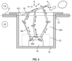
- the third example of the combination appliance 1 according to Fig. 4 comprises components and elements as described in the course of the first example of the combination appliance 1.
- the drive unit 34 for actuating an essentially plate-shaped and/or an essentially flat cover element 35 comprises an actuator unit 34A.
- the actuator unit 34A is preferably an electromechanical actuator unit 34A and comprises preferably a linkage assembly 34L.
- the cover element 35 is connected to the linkage assembly 34L and not further guided via guidance elements.
- the drive unit 34 further comprises at least one motor 34M for operating the linkage assembly 34L and thus actuating the cover element 35 accordingly.
- the linkage assembly 34L comprises at least one lifting cylinder that can be operated pneumatically or hydraulically additionally.
- the configuration as illustrated in Fig. 4 allows to actuate the cover element 35 translationally and/or rotationally and/or in an angular or oblique orientation with reference to the plane P21 being a reference plane of the cooktop plate 21.
- the cover element 35 comprises six degrees of freedom with regard to its possibilities of movement.
- a control unit 70 as illustrated in Fig. 1 controls the drive unit 34 dependent on at least one parameter relating to a cooking unit 22.1 to 22.4 in order to actuate the cover element 35 accordingly.
- the combination appliance 1 comprises display means 85, 87 arranged in the area of the recess 23 providing information to a user of the combination appliance 1 in different types of visualization.
- a first display means is provided by a light rim 85 arranged at a circumferential edge forming a border of the recess 23, which may be established by a plurality of stringed LED or by OLED stripes.
- a second display means is provided by a TFT display 87, preferably designed as a touch-screen unit, arranged on the top side of the cover element 35 facing the user of the combination appliance 1.
- the TFT display 87 may extend nearly over the entire top surface of the cover element 35, as roughly indicated in Figs. 5 to 9 .
- the illustration according to Fig. 5 represents an OFF state of the combination appliance 1 and no cookware is arranged on the cooktop plate 21. Only indicated in Figs. 5 to 9 is the electrical contact 89 between the control unit 70 or the user interface 40 of the combination appliance 1 with the TFT display 87 in order to supply the TFT display 87 with electrical power and/or with signals providing the information to be displayed.
- Said electrical contact 89 is established by electrical connection means, provided by a pair of connection elements (not shown in further detail in the figures), wherein the electrical contact 89 is configured to be interrupted, particularly when the cover element 35 is removed from the recess 23 in order to provide an access for the user to the filter unit 80 through the recess 23 for maintenance activities.
- Figs. 5 to 9 further includes three-pointed star symbols for illustrating the location of the cooking zones representing the cooking units 22.1 to 22.4 (instead of the schematic illustration as circles in Fig. 1 ), as well as a standard user interface 40 including one control bar 40.1 to 40.4 (only referenced in Fig. 5 , but shown also in Figs. 6 to 9 ) and one pair of seven-segment displays 40a to 40d (also only referenced in Fig. 5 ), respectively allocated to each one of the control bars 40.1 to 40.4 for each one of the four cooking zones 22.1 to 22.4.
- three-pointed star symbols for illustrating the location of the cooking zones representing the cooking units 22.1 to 22.4 (instead of the schematic illustration as circles in Fig. 1 ), as well as a standard user interface 40 including one control bar 40.1 to 40.4 (only referenced in Fig. 5 , but shown also in Figs. 6 to 9 ) and one pair of seven-segment displays 40a to 40d (also only referenced
- Fig. 6 the cooktop plate 21 of the combination appliance 1 is shown, wherein cooking zone 22.4 is occupied by a cooking vessel 50.
- a related segment of the light rim 85 is illuminated, that way indicating the presence of the cooking vessel 50 on the cooking zone 22.4.
- Such indication may be related to a specific colouring and/or to a specific blinking frequency.
- the same or a similar segment of the light rim 85 may indicate, particularly with a different colouring and/or blinking frequency, a residual heating indication, which means that the related cooking zone 22.4 is still hot after a finalization of a cooking process. This may go hand in hand with a respectively empty cooking zone 22.4. In both situations, i.e., with an only placement of a cooking vessel 50 on the cooking zone 22.4, or with a residual heating indication, the combination appliance 1 is not further operated, so that the TFT display 87 is in an OFF state, too.
- Fig. 7 represents the fume extraction device 30 being operated as an air purification device. Therefore, both lateral sides of the light rim 85 indicate this particular operation process by being illuminated, which may be performed by yet another colouring and/or blinking frequency. Moreover, also in this operational mode, there is no activation of the TFT display 87, particularly also because no cooking zone 22.1 to 22.4 is operated at this time.
- the recess 23, however, is partly covered by the cover element 35, but in order to provide a sufficient inlet opening for the aspirated air with fumes sourcing from the cooking vessels 50 on cooking zones 22.1, 22.2, the cover element 35 has been moved in the direction of cooking zones 22.3, 22.4, thereby being positioned adjacent to the related lateral side of the border surrounding the recess 23.
- the activation of the blower unit 31 of the fume extraction device 30 in order to aspirate the fumes sourcing from the cooking vessels 50 on cooking zones 22.1, 22.2 is also indicated to the user by an illumination of the related lateral side of the border next to the cooking zones 22.1, 22.2. Again, this illumination may be performed by yet another colouring and/or blinking frequency.
- Fig. 9 shows an actively operated TFT display 87
- this display means may be operated in any possible position it can be moved to. If, for example, instead of the cooking zones 22.1 and 22.2 at least one of the cooking zones 22.3, 22.4 will be occupied by cookware 50 and operated in order to perform a cooking process, the cover element 35 will be moved away from the lateral side of the recess 23 related to this at least one of cooking zones 22.3, 22.4 in order to provide a respectively great inlet opening for cooking fumes next to the operated cooking zone(s) 22.3, 22.4. Also in this position, different from that one shown in Figs. 8 and 9 , the TFT display 87 is operable.
- the cover element 35 is electrically connected to the control unit 70 of the fume extraction device 30 via an electrical contact 89 arranged at the border surrounding the recess 23.
- the electrical contact 89 is positioned at a rear side of the recess 23 (from a user's perspective), however, the electrical contact could be also located at the front side of the recess 23, or both the front and the rear side could be selected for a split contacting, e. g. with a plus contact being located at the rear side and a minus contact being located at the front side.
- the electrical contact 89 is also configured to be disconnected and reconnected.
- the combination appliance of the present embodiment includes an electrical contact 89, which comprises a sliding contact, which e. g. includes at least one moveable contact pin, preferably a spring-loaded contact pin or a magnetic pin, on the one hand, and at least one contact rail, on the other hand.
- the at least one contact pin is arranged at the cover element and connected there to the TFT display by wiring
- the at least one contact rail is arranged at the related border side of the recess 23 and connected there to the control unit 70 or the user interface unit 40.
- Fig. 8 illustrates the illumination for only the operation of the blower unit 31, what also can be the situation of a follower control of the blower unit 31 after finalization of the cooking process
- Fig. 9 additionally shows a display of operating parameters of related cooking zones 22.1, 22.2 by means of alphanumeric and symbol characters, specifically power levels, timer symbols and indication of an activated assisted cooking function 91. These characters are presented in a way making the allocation to the related cooking zone 22.1, 22.2 obvious.
- the power levels of the cooking zones 22.1, 22.2 may be presented by means of the seven-segment displays 40a, 40b, which illustrate by displaying "05" and "09” that the cooking zones 22.1, 22.2 are operated with power levels presently. This information is also provided on the TFT display 89.
Landscapes
- Engineering & Computer Science (AREA)
- Chemical & Material Sciences (AREA)
- Combustion & Propulsion (AREA)
- Mechanical Engineering (AREA)
- General Engineering & Computer Science (AREA)
- Ventilation (AREA)
Abstract
- a fan (31) for sucking air from the area (CS) above the cooking hob (20) through a suction opening (23) of the fume extraction device (30),
- a cover element (35), which is arranged at the suction opening (23), and
- at least one light source (85, 87), which is arranged in the area of the suction opening (23) and/or at or on the cover element (35). The at least one light source (85, 87) comprises a display means (85, 87) configured to provide visual information.
According to the invention, the cover element (35) is moveable from a first position to at least a second position, and the display means (87) is arranged at or on the moveable cover element (35) and is configured to display the visual information both in the first position and in the at least second position.
Description
- The present invention relates to a downdraft fume extraction device according to
claim 1. The present invention relates further to a combination appliance comprising a cooking hob and a fume extraction device according to claim 9 and to a method for operating a fume extraction device or a combination appliance according to claim 12. - In order to support persons in performing domestic work, household appliances of different kinds are known. In particular, cooking processes are performed using cooking appliances. For example, cooking hobs comprise cooking zones for placement of cookware receiving the food to be cooked. The cooking zones are generally arranged on a cooktop, in particular a glass ceramic cooktop, which forms an upper wall of the cooking hob. During cooking processes under use of such cooking hobs, cooking fumes are generated, which are distributed over the cooking area. In order to avoid these cooking fumes to be spread throughout the entire kitchen space, it is common to arrange an extraction hood above the cooking area for an aspiration of these fumes. Also downdraft fume extraction devices are known, which are arranged or arrangeable below a worktop of a kitchen furniture, particularly in a side-by-side arrangement with a cooking hob. Moreover, there are also cooking hobs known, in which such a cooking fumes extraction functionality is integrated. More specifically, such kind of a combination appliance comprises a cooking hob and an integrated downdraft extraction device with an extraction opening in the cooktop of the cooking hob. With this combination of a cooking hob and an extraction device, a compact solution is provided. Extraction hood or extraction device can be operated in parallel to the cooking hob, thereby sucking in those cooking fumes in order to filter out particles and tiny droplets and/or to blow the cooking fumes to the outside of the building.
- There are also solutions known, which use the extraction opening of the suction opening for fume extraction of said combination appliance also for a display of status information of the combination appliance. In particular, the document
EP 3 951 267 A1 discloses a combination appliance comprising a cooking hob and an extraction device, in which air is sucked through a recess of a support surface, and which comprises a lid for covering the recess. An illumination device comprising light sources is arranged in the area of the recess and is configured to provide information about operating parameters of the combination appliance to the user by changing one or more light parameters over time. - It is an object of the present invention to provide a fume extraction device, a combination appliance, which comprises a cooking hob and a fume extraction device, and a method for operating a fume extraction device or a combination appliance, which provide or provides not only a high fume extraction performance adaptable to current cooking activities, but also a clear visualization of information relevant for the user of the device or appliance at any time during the operation of the device or appliance.
- The object is achieved for a fume extraction device, more specifically a downdraft fume extraction device, according to a first aspect of the present invention, according to the preamble of
claim 1 by the features of the characterizing part ofclaim 1. - According to said first aspect, a fume extraction device is provided, which is arranged or arrangeable below a worktop. The fume extraction device is particularly designed using the downdraft principle with sucking air in downwards direction. The fume extraction device in general comprises a fan for sucking air from the area above the cooking hob through a suction opening of the fume extraction device, a cover element, which is arranged at the suction opening, and at least one light source. The cover element is preferably a flat and/or plate-shaped cover element and/or is configured to partially or completely cover the suction opening. The at least one light source is arranged in the area of the suction opening. Additionally or alternatively, the at least one light source is arranged at or on the cover element. Moreover, the at least one light source comprises a display means configured to provide visual information to a user of the fume extraction device. In particular, the at least one light source is configured to display an operational parameter and/or status information of the fume extraction device. Additionally, or alternatively, information about status or parameters of a cooking process may particularly be displayable. A preferred embodiment of the fume extraction device also includes at least one filter element for removing particles and/or odours from the air sucked in, which air may comprise fumes from a cooking process, so that the at least one filter element particularly provides a grease and/or odour filter function. According to the present invention, the cover element is moveable from a first position to at least a second position, and the display means is arranged at or on the moveable cover element and is configured to display the visual information both in the first position and in the at least second position of the cover element. The first position and the at least a second position particularly differ from each other in a horizontal displacement and/or in a vertical displacement and/or in an angular alignment. By this means, the cover element and/or the display means is or are designed in such a manner as to provide the visual information wherever the cover element is currently positioned, which position may depend on a specific operational mode and/or on a specific process step.
- More specifically, said first position and at least a second position may also mean that the cover element can be positioned arbitrarily and electrical connection is possible on a continuous path.
- The fume extraction device may be assigned to or included in a cooking hood. In addition to potential grease and/or odour filtering properties, the at least one filter element may also be adapted for a filtering of other substances or compounds of specifically cooking fumes, such as vapours or volatile organic compounds. Moreover, the at least one filter element may be arranged or arrangeable in a fixed filter holder, but preferably it is supported by a filter carrier, which advantageously is removable from its operative position, particularly removable from the fume extraction unit.
- The extraction device may further include an outlet opening for exhaust air, which may be exhausted into the ambient air. In that, the fan may be provided for sucking air from the area above the cooking hob through the suction opening of the cover plate or worktop and for conveying it through an air duct of the extraction device comprising the at least one filter element to the outlet opening. Further, the filter element may be arranged or arrangeable upstream of the fan and downstream of the suction opening.
- The object is achieved for a fume extraction device, more specifically a downdraft fume extraction device, according to a second aspect of the present invention, according to the preamble of claim 2 by the features of the characterizing part of claim 2.
- According to said second aspect, a fume extraction device is provided, which is arranged or arrangeable below a worktop. The fume extraction device is particularly designed using the downdraft principle with sucking air in downwards direction. The fume extraction device in general comprises a fan for sucking air from the area above the cooking hob through a suction opening of the fume extraction device, a cover element, which is arranged at the suction opening, and at least one light source. The cover element is preferably a flat and/or plate-shaped cover element and/or is configured to partially or completely cover the suction opening. The at least one light source is arranged in the area of the suction opening. Additionally or alternatively, the at least one light source is arranged at or on the cover element. Moreover, the at least one light source comprises a display means configured to provide visual information to a user of the fume extraction device. In particular, the at least one light source is configured to display an operational parameter and/or status information of the fume extraction device. Additionally, or alternatively, information about status or parameters of a cooking process may particularly be displayable. A preferred embodiment of the fume extraction device also includes at least one filter element for removing particles and/or odours from the air sucked in, which air may comprise fumes from a cooking process, so that the at least one filter element particularly provides a grease and/or odour filter function. The fume extraction device according to the second aspect of the invention may be a specific design of the fume extraction device according to the first aspect of the invention. According to the present invention, the display means comprises at least one display element for a display of alphanumeric and/or symbol characters. The display element preferably includes at least one of an LED display, an OLED display, an LCD display, a TFT display, and a seven-segment display. Such types of characters particularly have an increased explanatory power compared to any kind of light signals, possibly differentiated by intensity, colouring and/or blinking frequency. The cover element may be a grid or any kind of covering means with full-surface or part surface extension, particularly at least temporarily fully or partly covering the suction opening. The cover element may be designed as a fixed and/or immovable element, or it may be configured to cover only sections of the suction opening, but changing sections at different times.
- Also the fume extraction device according to the second aspect of the present invention may be assigned to or included in a cooking hood. In addition to potential grease and/or odour filtering properties, the at least one filter element may also be adapted for a filtering of other substances or compounds of specifically cooking fumes, such as vapours or volatile organic compounds. Moreover, the at least one filter element may be arranged or arrangeable in a fixed filter holder, but preferably it is supported by a filter carrier, which advantageously is removable from its operative position, particularly removable from the fume extraction unit.
- The extraction device may further include an outlet opening for exhaust air, which may be exhausted into the ambient air. In that, the fan may be provided for sucking air from the area above the cooking hob through the suction opening of the cover plate or worktop and for conveying it through an air duct of the extraction device comprising the at least one filter element to the outlet opening. Further, the filter element may be arranged or arrangeable upstream of the fan and downstream of the suction opening.
- Moreover, the cover element may be electrically connected to a control unit of the fume extraction device, so that an operative control may be centrally performable. Additionally or alternatively, at least a part of a control functionality may be outsourced to a unit arranged on the cover element. The connection between the control unit of the extraction device and the light source on the cover element, specifically the display means, is particularly established via an electrical contact, in particular at least one contact element or contact pair. Said electrical contact may be arranged in the area, more particularly at a rim or border, surrounding the suction opening.
- More specifically, in order to provide access to the interior of the suction opening for the user, e. g. for cleaning the interior space and/or for cleaning or replacing the filter element that may be accessible through the suction opening, the cover element is preferably removably arranged at the suction opening, more preferably removably arranged within the area of the suction opening, and the electrical connection is configured to be disconnected and reconnected. In particular, the electrical connection is configured to be interrupted at the electrical contact, in particular by disconnecting the at least one contact pair.
- According a specific embodiment, the electrical connection, in particular the electrical contact, comprises a plurality of contact points discretely arranged in a row arranged in the area, which surrounds the suction opening. Said surrounding area is more specifically a rim or border of or around the suction opening. As an alternative, the electrical connection may be established by a sliding contact, which may provide a continuous maintaining of the electrical connection between display means and control unit, whichever position may be the current one for the cover element. A particular embodiment is characterized in that at least one moveable contact pin and at least one fixed contact rail are included.
- Advantageously, the electrical connection is a multicore connection including at least two electrical wires and comprises at least a first contact pair and a second contact pair. The first and second contact pairs may be arranged at the same side of the cover element. As an alternative, the first and second contact pairs may be arranged at different sides, preferably at opposite sides, of the cover element, which may particularly be relevant in the case of a rectangular cover element. Independently from the arrangement of the contact pairs, an incorrect placement, e. g. an upside-down arrangement, of the cover element may be prevented by a protection means for misplacement.
- According to embodiments, the at least one light source comprises at least one illuminable lateral edge, preferably an illuminable rim, which particularly comprises or is covered with an LED array, a plurality of single LED and/or an OLED light strip.
- In some implementations, the at least one illuminable lateral edge, in particular the illuminable rim, is arranged at the edge of the suction opening and/or at the circumferential edge of the cover element.
- The object is further achieved for a combination appliance by the combination of the features of claim 9.
- According to a third aspect of the present invention, a combination appliance comprises a cooking hob and a fume extraction device as herein disclosed, particularly as previously described in general or by embodiments. The cooking hob comprises a cover plate or worktop, which has an opening or a recess formed therein. The cover plate or worktop is in particular a glass plate. The fume extraction device is arranged below the cooking hob, in particular below the cover plate or worktop of the cooking hob. Said opening or recess forms the suction opening of the fume extraction device.
- The cooking hob may be of any type including electric or gas cooking hobs. In particular, an induction cooking hob is a part of the combination appliance. The cooking hob may further be an autarkic cooking appliance, particularly integrated in a countertop of kitchen furniture, or it may be part of a stove.
- A top surface of the cover plate or worktop, which is accessible to a user of the combination appliance, may be used for putting cookware thereon, specifically in order to perform a cooking process. To this end, the cooking hob preferably comprises at least one heating element defining a cooking zone on the cover plate or worktop. The cover plate or worktop may be of any suitable design or material, but favourably it is made out of glass, notably of glass ceramics.
- One preferred solution of the invention is characterized in that the light source, specifically the display means, is configured to display operational parameters and/or status information of the fume extraction device and/or of the cooking hob. The display means is preferably configured to display information supporting a user to perform a cooking process, which information is specifically a recipe information or any information related to a proper use of the cooking hob or the fume extraction device.
- In order to provide an advanced solution for a combination appliance, specifically related to an ease of operation, at least a section or zone of the display means may be designed to be touch sensitive. By providing such at least one specific section or zone, an input means for the selection of a specific cooking zone on the cover plate or worktop of the cooking hob may be available, preferably next to the specific zone, which not only indicates to the user a dedicated assignment between this particular input means and the related cooking zone, but also allows a simple selection of this cooking zone, e. g. for the selection of a power level, with which the cooking zone shall be operated.
- Moreover, in addition or alternatively to the specific selection of a cooking zone, the at least a section or zone of the display means may be useable for an activation of a function of the fume extraction device. This may include setting a power level or a rotational speed of the fan in order to set a specific suction force, which may depend on the amount of cooking fumes arising from the actual cooking process. The fume extraction device may be designed in a way as to steer the suction force to a certain suction direction, i. e. focussed on a fume source. In that case it is favourable to allocate the section or zone of the display means to a specific cooking zone on the cover plate or worktop of the cooking hob for a control of the suction direction. In a particular specific embodiment, a displacement of the cover element may be performable, notably by a specific selection or operation of the at least a section or zone of the display means in order to provide a relevant inlet opening for cooking fumes related to the specific cooking zone.
- The object is also achieved by a method for operating a fume extraction device or a combination appliance, which comprises a cooking hob and an extraction device, according to the preamble of claim 12 by the characterizing part of claim 12.
- According to a fourth aspect of the present invention, a method for operating a fume extraction device or a combination appliance, which comprises a cooking hob and a fume extraction device, is provided. The fume extraction device and/or the combination appliance may be designed as herein disclosed, particularly as previously described in general or by embodiments. According to this method, the fume extraction device or the combination appliance sucks in fumes, in particular cooking fumes, through a suction opening of the fume extraction device. Further, a cover element, which is preferably flat and/or plate-shaped, is arranged at the suction opening. The cover element preferably partially covers the suction opening at least during at least one process step. In the at least one process step at least one light source of the fume extraction device or of the combination appliance provides visual information. Said light source comprises a display means and is arranged in the area of the suction opening and/or at or on the cover element. The visual information provided by the at least one light source of the fume extraction device or of the combination appliance may be about an operational parameter and/or status information of the fume extraction device and/or of the cooking hob. Additionally, or alternatively, information about status or parameters of a cooking process may particularly be displayed. According to the present invention, the cover element is moveably arranged at the suction opening and the at least one light source, which may be the display means that is arranged at or on the moveable cover element, provides the visual information in the current position in which the cover element is located during the at least one process step. That means that the cover element may be located at any arbitrary position, whichever position is possible and accessible by the cover element, and in each position the display of the visual information is enabled. That way it is possible to display the information that currently shall be provided, without taking care of the actual position of the cover element. According to a fifth aspect of the present invention, a method for operating a fume extraction device or a combination appliance, which comprises a cooking hob and a fume extraction device, is provided. The fume extraction device and/or the combination appliance may be designed as herein disclosed, particularly as previously described in general or by embodiments. According to this method, the fume extraction device or the combination appliance sucks in fumes, in particular cooking fumes, through a suction opening of the fume extraction device. Further, a cover element, which is preferably flat and/or plate-shaped, is arranged at the suction opening. The cover element preferably partially covers the suction opening at least during at least one process step. In the at least one process step at least one light source of the fume extraction device or of the combination appliance provides visual information. Said light source comprises a display means and is arranged in the area of the suction opening and/or at or on the cover element. The visual information provided by the at least one light source of the fume extraction device or of the combination appliance may be about an operational parameter and/or status information of the fume extraction device and/or of the cooking hob. Additionally, or alternatively, information about status or parameters of a cooking process may particularly be displayed. According to the present invention, the visual information provided on the cover element comprises at least one alphanumeric and/or symbol characters.
- The cover element may be a grid or any kind of covering means with full-surface or part surface extension, particularly at least temporarily fully or partly covering the suction opening. The cover element may be fixed positioned in or at the suction opening and/or immovable at all times, or it may be cover only sections of the suction opening, but changing sections at different times.
- A preferred embodiment of the method according to the fourth aspect or according to the fifth aspect of the present invention is characterized in that the at least one light source comprises a light rim arranged at the edge of the suction opening and/or of the cover element, which at least one light source indicates by means of a specific light presentation method at least one of the following status information or error massages.
- a. A residual heating indication by means of a specific light signal may inform the user of a heated cooking zone of the cooking hob, wherein the way and/or position of the light signal may be related to a particular cooking zone of the cooking hob.
- b. An indication of a detection of cookware to be present or to have been placed on a particular cooking zone of the cooking hob is visualized to the user. In excess of a pure visualization, preferably the cooking zone is triggered to form a selected cooking zone.
- c. An indication of a wrong or a less favourable positioning of cookware on a cooking zone suggests the user to better position the cookware in order to optimize the cooking performance.
- d. An indication of a wrong or a less favourable positioning of the cover element at the suction opening may inform the user of at least reduced functionality of the cover element and/or of display means arranged at the cover element, which could motivate the user to correct the positioning of the cover element.
- e. An indication of a wrong positioning of a filter element in the fume extraction device, informs the user of an at least reduced filtering performance of the fume extraction device.
- f. An indication of the operation of a fan of the fume extraction device visually informs the user of an operating fan, which is supportive in case of acoustically not recognizable low fan speeds.
- g. An operation of a particular cooking zone of the cooking hob is displayed to the user, particularly providing information about a cooking process.
- h. A visualization is provided for information about air quality, in particular provided by at least one air quality sensor.
- i. An activation of an air purification filter is provided to the user, preferably an activation of a PECO filter comprised by the fume extraction device.
- One specific embodiment provides for at least one light source that is activated or triggered or controlled by a user interface input, which is particularly dependent on a selected cooking zone and/or a selected operating mode of the fume extraction device. Another specific embodiment, which may be an addition or an alternative, provides for at least one light source that is activated or triggered or controlled by an input of a measuring or detection means. Said measuring or detection means is in particular a detection means for detection of the current position of cookware on the related cooking zone and/or a sensor for at least one of a humidity level, a temperature level, and a presence or amount of volatile organic compounds, wherein these parameters temperature, humidity and volatile organic compounds, which may cause odours, in general can work as an indication for the current air quality.
- In some implementations, at least one of the methods according to the present invention is characterized in that during at least one process step, the at least one light source visualizes an operation of the fume extraction device as an air purification device. During this operation, a sanitation device preferably performs an air purification and/or a neutralization of microbiological contamination of the treated air. Such kind of air treatment may be performed independently from any fume extraction operation.
- Novel and inventive features of the present invention are set forth in the appended claims.
- The present invention will be described in further detail with reference to the drawings, in which
- Fig. 1
- illustrates schematically a perspective view of a combination appliance comprising a recess with a cover element according to a first example;
- Fig. 2
- illustrates schematically a top view of a cut-out area around the recess in the cooktop plate of the combination appliance as illustrated in
Fig. 1 ; - Fig. 3
- illustrates schematically a top view of a second example of a cut-out area around a recess of the combination appliance;
- Fig. 4
- illustrates schematically a cross-sectional view of a third example of a cut-out area around a recess of the combination appliance;
- Fig. 5
- illustrates a top view of an actual embodiment of a combination appliance similar to the first example according to
Fig. 1 comprising display means in the area of the recess; - Fig. 6
- illustrates the combination appliance according to
Fig. 5 , but with visualization of a first operational state; - Fig. 7
- illustrates the combination appliance according to
Fig. 5 , visualizing a second operational state; - Fig. 8
- illustrates the combination appliance according to
Fig. 5 , visualizing a third operational state; and - Fig. 9
- illustrates the combination appliance according to
Fig. 5 , visualizing the third operational state shown byFig. 8 , and additionally providing information about cooking hob parameters. - Identical or functionally equivalent components or elements are marked or labeled in the figures with the same reference signs. For their explanation, reference is also made to the description of other examples and/or figures in order to avoid repetition.
- The following detailed description of the examples shown in the figures serves as a closer illustration or exemplification and is in no way intended to limit the scope of the present invention.
-
Fig. 1 illustrates schematically a first example of acombination appliance 1, which comprises ahob 20 and afume ex-traction device 30. Thehob 20 comprises acooktop plate 21 and cooking units 22.1 to 22.4 on a cooking side CS, which represents the area above thecooktop plate 21 accessible to the user of the combination appliance for performing the cooking process. Thecooktop plate 21 is preferably configured essentially plate-shaped and/or essentially flat. Thecooktop plate 21 is made, for example, of a glass-ceramic material. The orientation of thecooktop plate 21 may be described by a plane P21. The plane P21 is preferably a definable or determinable mid-plane or a reference plane of thecooktop plate 21. In the operating status or in an installed status of thecombination appliance 1, thecooktop plate 21 is arranged substantially horizontally. - The cooking units 22.1 to 22.4 are preferably induction cooking units 22.1 to 22.4 each comprising at least an induction coil and a power board (not shown in the figures for reasons of clarity). Alternatively, the cooking units 22.1 to 22.4 are configured differently with regard to the principle of generating heat, for example, as heating coils, gas burners or the like.
- A
cooking vessel 50 is placed on cooking unit 22.1 inFig. 1 and cooking unit 22.1 is activated for food preparation thus generating fumes by heating the content of thecooking vessel 50. Fumes comprise in particular at least grease and/or odors. - The
cooktop plate 21 further comprises arecess 23 with arecess cross-section 23A or defining arecess cross-section 23A. Therecess 23 is formed in thecooktop plate 21 of thehob 20. - The
recess cross-section 23A may comprise, according toFigs. 1 and2 , an essentially rectangular contour in a view, preferably in a top view. However, the second example according toFig. 3 shows that therecess cross-section 23A may alternatively comprise an essentially circular or an oval contour in a view, preferably in a top view. - In other words, the
recess cross-section 23A forms at least partially or at least in sections the flow cross-section of the fumes at the entrance intofume extraction device 30, hence forming a suction opening for thefume extraction device 30, which will be described in further detail in the following. - The
fume extraction device 30 comprises aflow channel 32 for guiding, preferably extracting, fumes from the cooking side CS of thehob 20 through therecess 23 in the direction X of ablower unit 31 of thefume extraction device 30, which includes a fan wheel and a drive element such as an electric motor for driving the fan wheel in order to generate an extraction effect. Theblower unit 31 is arranged below thecooktop plate 21 on the apparatus side AS, which is opposite to the cooking side CS with reference to thecooktop plate 21, preferably the plane P21 related to thecooktop plate 21. - An
inlet cavity 33 is arranged in or formed at therecess 23, preferably at the apparatus side AS. Theinlet cavity 33 may be designed box-shaped. Theinlet cavity 33 is in flow connection with theflow channel 32 and comprises or is connected to acover element 35 for covering at least partially therecess 23 and preferably at least partially therecess cross-section 23A thus influencing a (resulting) flow cross-section of the fumes to be extracted from thehob 20. - The
inlet cavity 33 further comprises adrive unit 34. Thedrive unit 34 may be configured as an electromechanical drive unit or as a pneumatic drive unit or as a hydraulic drive unit or a combination thereof, which will be described in further detail below. - The
cover element 35 is configured for actuation by thedrive unit 34 in order to at least partially cover therecess cross-section 23A on the basis of at least one parameter relating to at least one of the cooking units 22.1 to 22.4. In other words, thecover element 35 is a movable and/or dynamic element being driven, i.e., actuated by thedrive unit 34 in order to further optimize the extraction effect of thefume extraction device 30. - The
cover element 35 may be configured essentially plate-shaped and/or flat. In other words, thecover element 35 may be formed as an essentially flat shield or an essentially flat lid. - The
combination appliance 1 further comprises several or a plurality of sensor units 60.1 to 60.4. At least one sensor unit 60.1, 60.2 is preferably arranged and/or integrated in thecooktop plate 21. It is possible that a further at least one sensor unit 60.3, 60.4 is arranged in theflow channel 32 upstream theblower unit 31. Afilter unit 80 of thefume extraction device 30, comprising at least one grease filter element and/or at least one odor filter element, may be arranged in theflow channel 32 between a third sensor unit 60.3 and a fourth sensor unit 60.4. - A sensor unit 60.1 to 60.4 preferably comprises at least one of the following: temperature sensor, humidity sensor and/or a (total) volatile compound (TVOC/VOC) sensor, at least the latter one being configured to detect air quality at least in the region between the
recess 23 and thus theinlet cavity 33 and the first cooking unit 22.1 and/or second cooking unit 22.2. The at least one parameter may relate to at least one of the cooking units 22.1 to 22.4. - With regard to the
cover element 35 as illustrated inFig. 1 , it is configured to be actuated translationally by thedrive unit 34. In addition, or alternatively, thedrive unit 34 may be configured to actuate thecover element 35 rotationally. - The translational movement options, i.e., in this case directions of possible displacement of the
cover element 35, are indicated inFig. 1 in the area of thecover element 35 by the double arrow. - The
cover element 35 can be actuated by thedrive unit 34 either in the direction of the cooking units 22.1 and 22.2 or in the direction of the cooking units 22.3 and 22.4 and thus changing the size of therecess cross-section 23A and/or the position or location of the (effective) flow cross-section of the fumes to be extracted from thehob 20. - The
combination appliance 1 further comprises auser interface unit 40 for a user of thecombination appliance 1 to operate at least one of the cooking units 22.1 to 22.4 and/or theblower unit 31 of thefume extraction device 30. - In addition, the
combination appliance 1 comprises acontrol unit 70 that may be preferably anelectronic control unit 70. Thecontrol unit 70 may be a separate component of thecombination appliance 1 or may be integrated, for example, in theuser interface unit 40. Thecontrol unit 70 can control at least one of the cooking units 22.1 to 22.4, i.e., preferably power boards of the cooking units 22.1 to 22.4 in the present example of thecombination appliance 1 and/or theblower unit 31 of thefume extraction device 30 of thecombination appliance 1. - The
control unit 70 may be configured for controlling thedrive unit 34 dependent on the at least one parameter, inter alia preferably detected by at least one sensor unit 60.1 to 60.4 of thecombination appliance 1. - The
control unit 70 may be connected at least to the cooking units 22.1 to 22.4, the sensor units 60.1 to 60.4, theblower unit 31 and thedrive unit 34 via a data bus system (not shown in the figures for reasons of clarity) for signal communication and may control these components in a closed loop configuration. In other words, thecontrol unit 70 may control theblower unit 31 and/or thedrive unit 34 dependent on the operating status of the cooking unit 22.1 and/or a parameter being in relation to the cooking unit 22.1 such as temperature of the cooking unit 22.1 and/or temperature of the content of thecooking vessel 50, air quality and/or air composition at least between therecess 23 and the cooking unit 22.1. Controlling theblower unit 31 may comprise adjusting the rotational speed of the fan wheel of theblower unit 31 via the drive element, i.e., the electric motor, of the fan wheel. - Further, controlling the
drive unit 34 may comprise or result in actuating thecover element 35 translationally in direction towards the cooking unit 22.1 (and the cooking unit 22.2) or in a direction away from the cooking unit 22.1 (and the cooking unit 22.2), which leads to an adjustment (increase or decrease) of theaccessible recess cross-section 23A of therecess 23 and thus the (resulting) flow cross-section of the fumes to be extracted from thehob 20. This allows more or less an automatic and, in particular, optimized adjustment of the suction effect to the respective cooking conditions or cooking processes. - It is possible that at least one parameter further comprises information relating to detection of a
cooking vessel 50 on at least one cooking unit 22.1 to 22.4. - The relation between the
drive unit 34 and thecover element 35 and their configuration is described exemplary in further detail in the following. -
Fig. 2 illustrates schematically a top view of the region of therecess 23 in thecooktop plate 21 of thecombination appliance 1 as illustrated inFig. 1 . - The
recess 23 in thecooktop plate 21 comprises arecess cross-section 23A of essentially rectangular shape or contour. Theinlet cavity 33 may be configured at least in sections channel-like or tub-shaped and comprises corresponding walls and/or wall sections of corresponding thicknesses (not explicitly labelled in the figures for reasons of clarity). Theinlet cavity 33 may be configured as a separate part and inserted into therecess 23 at least in sections. It is also possible that theinlet cavity 33 is part of theflow channel 32, being preferably formed integrally with at least a channel section of theflow channel 32. - The
drive unit 34 preferably comprises anactuator unit 34A in the sense of anelectromechanical actuator unit 34A that is operatively coupled to thecover element 35 for translational actuating thecover element 35 in at least one direction as illustrated graphically inFig. 2 by the double arrow. Theactuator unit 34A comprises alinkage assembly 34L. Thedrive unit 34 further comprises amotor 34M with a rotor and a stator. Thecover element 35 is connected to themotor 34M, preferably the rotor of themotor 34M, via thelinkage assembly 34L such that themotor 34M may actuate thecover element 35 correspondingly via thelinkage assembly 34L and dependent on at least one parameter as described above. Thelinkage assembly 34L may comprise a plurality of links being connected to each other at least partially via joint connections. - In order to realize the movement of the
cover element 35, thecombination appliance 1 comprises a first guidance element 36.1 and a second guidance element 36.2. The first and the second guidance elements 36.1, 36.2 are preferably arranged in theinlet cavity 33 of thefume extraction device 30. - The first guidance element 36.1 and the second guidance element 36.2 allow a translational guidance of the
cover element 35 that is mounted into or onto the guidance elements 36.1, 36.2 via, for example, a sled section of the cover element 35 (not explicitly labelled inFig. 2 for the sake of clarity). The guidance elements 36.1, 36.2 may comprise a guide rail formed as a slide rail or formed as a ball bearing rail. -
Fig. 3 illustrates schematically a top view of a second example of a cut-out area around a recess of thecombination appliance 1. The second example of thecombination appliance 1 may comprise components and elements as described in the course of the first example of thecombination appliance 1. - As illustrated by
Fig. 3 , therecess 23 comprises an essentiallycircular contour 23C. Further, thecover element 35 comprises an essentiallycircular contour 35C being mounted movable in the region of therecess 23 viadrive unit 34. Thedrive unit 34 comprises anactuator unit 34A and is configured to actuate translationally thecover element 35 dependent on at least one parameter as described above. - In other words, the
cover element 35 may be inter alia pivoted by thedrive unit 34 with theactuator unit 34A to different positions within therecess 23, thereby changing the size and position of theaccessible recess cross-section 23A according to or dependent on a cooking process. - The third example of the
combination appliance 1 according toFig. 4 comprises components and elements as described in the course of the first example of thecombination appliance 1. - As it can be retrieved from
Fig. 4 , thedrive unit 34 for actuating an essentially plate-shaped and/or an essentiallyflat cover element 35 comprises anactuator unit 34A. Theactuator unit 34A is preferably anelectromechanical actuator unit 34A and comprises preferably alinkage assembly 34L. Thecover element 35 is connected to thelinkage assembly 34L and not further guided via guidance elements. Thedrive unit 34 further comprises at least onemotor 34M for operating thelinkage assembly 34L and thus actuating thecover element 35 accordingly. It is possible that thelinkage assembly 34L comprises at least one lifting cylinder that can be operated pneumatically or hydraulically additionally. - The configuration as illustrated in
Fig. 4 allows to actuate thecover element 35 translationally and/or rotationally and/or in an angular or oblique orientation with reference to the plane P21 being a reference plane of thecooktop plate 21. In other words, thecover element 35 comprises six degrees of freedom with regard to its possibilities of movement. - A
control unit 70 as illustrated inFig. 1 controls thedrive unit 34 dependent on at least one parameter relating to a cooking unit 22.1 to 22.4 in order to actuate thecover element 35 accordingly. - In the following and with reference to
Figs. 5 to 9 , an actual embodiment of thecombination appliance 1 similar to the previously described first example according toFig. 1 will be explained. Thecombination appliance 1 comprises display means 85, 87 arranged in the area of therecess 23 providing information to a user of thecombination appliance 1 in different types of visualization. A first display means is provided by alight rim 85 arranged at a circumferential edge forming a border of therecess 23, which may be established by a plurality of stringed LED or by OLED stripes. A second display means is provided by aTFT display 87, preferably designed as a touch-screen unit, arranged on the top side of thecover element 35 facing the user of thecombination appliance 1. TheTFT display 87 may extend nearly over the entire top surface of thecover element 35, as roughly indicated inFigs. 5 to 9 . The illustration according toFig. 5 represents an OFF state of thecombination appliance 1 and no cookware is arranged on thecooktop plate 21. Only indicated inFigs. 5 to 9 is theelectrical contact 89 between thecontrol unit 70 or theuser interface 40 of thecombination appliance 1 with theTFT display 87 in order to supply theTFT display 87 with electrical power and/or with signals providing the information to be displayed. Saidelectrical contact 89 is established by electrical connection means, provided by a pair of connection elements (not shown in further detail in the figures), wherein theelectrical contact 89 is configured to be interrupted, particularly when thecover element 35 is removed from therecess 23 in order to provide an access for the user to thefilter unit 80 through therecess 23 for maintenance activities. - The actual embodiment according to
Figs. 5 to 9 further includes three-pointed star symbols for illustrating the location of the cooking zones representing the cooking units 22.1 to 22.4 (instead of the schematic illustration as circles inFig. 1 ), as well as astandard user interface 40 including one control bar 40.1 to 40.4 (only referenced inFig. 5 , but shown also inFigs. 6 to 9 ) and one pair of seven-segment displays 40a to 40d (also only referenced inFig. 5 ), respectively allocated to each one of the control bars 40.1 to 40.4 for each one of the four cooking zones 22.1 to 22.4. - By
Fig. 6 thecooktop plate 21 of thecombination appliance 1 is shown, wherein cooking zone 22.4 is occupied by acooking vessel 50. With said occupation of cooking zone 22.4, a related segment of thelight rim 85 is illuminated, that way indicating the presence of thecooking vessel 50 on the cooking zone 22.4. Such indication may be related to a specific colouring and/or to a specific blinking frequency. On the other hand, the same or a similar segment of thelight rim 85 may indicate, particularly with a different colouring and/or blinking frequency, a residual heating indication, which means that the related cooking zone 22.4 is still hot after a finalization of a cooking process. This may go hand in hand with a respectively empty cooking zone 22.4. In both situations, i.e., with an only placement of acooking vessel 50 on the cooking zone 22.4, or with a residual heating indication, thecombination appliance 1 is not further operated, so that theTFT display 87 is in an OFF state, too. -
Fig. 7 represents thefume extraction device 30 being operated as an air purification device. Therefore, both lateral sides of thelight rim 85 indicate this particular operation process by being illuminated, which may be performed by yet another colouring and/or blinking frequency. Moreover, also in this operational mode, there is no activation of theTFT display 87, particularly also because no cooking zone 22.1 to 22.4 is operated at this time. - In contrast to the situation represented by
Fig. 6 , byFig. 8 not only an occupation of the cooking zones 22.1 and 22.2 by cookingvessels 50 is presented, but also an operation of thefume extraction device 30 is indicated. When performing cooking activities, cooking fumes are created in the way as illustrated inFig. 1 , which cooking fumes are sucked in by thefume extraction device 30 through therecess 23. Therecess 23, however, is partly covered by thecover element 35, but in order to provide a sufficient inlet opening for the aspirated air with fumes sourcing from thecooking vessels 50 on cooking zones 22.1, 22.2, thecover element 35 has been moved in the direction of cooking zones 22.3, 22.4, thereby being positioned adjacent to the related lateral side of the border surrounding therecess 23. Moreover, the activation of theblower unit 31 of thefume extraction device 30 in order to aspirate the fumes sourcing from thecooking vessels 50 on cooking zones 22.1, 22.2 is also indicated to the user by an illumination of the related lateral side of the border next to the cooking zones 22.1, 22.2. Again, this illumination may be performed by yet another colouring and/or blinking frequency. - Even though only
Fig. 9 shows an actively operatedTFT display 87, it is to be noted that this display means may be operated in any possible position it can be moved to. If, for example, instead of the cooking zones 22.1 and 22.2 at least one of the cooking zones 22.3, 22.4 will be occupied bycookware 50 and operated in order to perform a cooking process, thecover element 35 will be moved away from the lateral side of therecess 23 related to this at least one of cooking zones 22.3, 22.4 in order to provide a respectively great inlet opening for cooking fumes next to the operated cooking zone(s) 22.3, 22.4. Also in this position, different from that one shown inFigs. 8 and9 , theTFT display 87 is operable. In order to electrically drive theTFT display 87, thecover element 35 is electrically connected to thecontrol unit 70 of thefume extraction device 30 via anelectrical contact 89 arranged at the border surrounding therecess 23. According the illustrations ofFigs. 5 to 9 , theelectrical contact 89 is positioned at a rear side of the recess 23 (from a user's perspective), however, the electrical contact could be also located at the front side of therecess 23, or both the front and the rear side could be selected for a split contacting, e. g. with a plus contact being located at the rear side and a minus contact being located at the front side. - Moreover, since the
cover element 35 is removably arranged on or in therecess 23, theelectrical contact 89 is also configured to be disconnected and reconnected. In order to provide such anelectrical contact 89, which both is disconnectable and provides for anoperable TFT display 87 in at least two different positions of thecover element 35, the combination appliance of the present embodiment includes anelectrical contact 89, which comprises a sliding contact, which e. g. includes at least one moveable contact pin, preferably a spring-loaded contact pin or a magnetic pin, on the one hand, and at least one contact rail, on the other hand. For example, the at least one contact pin is arranged at the cover element and connected there to the TFT display by wiring, and the at least one contact rail is arranged at the related border side of therecess 23 and connected there to thecontrol unit 70 or theuser interface unit 40. - While
Fig. 8 illustrates the illumination for only the operation of theblower unit 31, what also can be the situation of a follower control of theblower unit 31 after finalization of the cooking process,Fig. 9 additionally shows a display of operating parameters of related cooking zones 22.1, 22.2 by means of alphanumeric and symbol characters, specifically power levels, timer symbols and indication of an activated assistedcooking function 91. These characters are presented in a way making the allocation to the related cooking zone 22.1, 22.2 obvious. As further shown inFig. 9 , the power levels of the cooking zones 22.1, 22.2 may be presented by means of the seven-segment displays TFT display 89. - The present invention is not limited to the examples described above. Rather, a large number of variants and modifications are possible, which also make use of the inventive idea and therefore fall within the scope of protection.
-
- 1
- combination appliance
- 20
- hob
- 21
- cooktop plate
- 22.1
- cooking unit/zone
- 22.2
- cooking unit/zone
- 22.3
- cooking unit/zone
- 22.4
- cooking unit/zone
- 23
- recess
- 23A
- recess cross-section
- 23C
- contour
- 30
- fume extraction device
- 31
- blower unit
- 32
- flow channel
- 33
- inlet cavity
- 34
- drive unit
- 34A
- actuator unit
- 34L
- linkage assembly
- 34M
- motor
- 35
- cover element
- 36.1
- guidance element
- 36.2
- guidance element
- 40
- user interface unit
- 40.1 ... 40.4
- control bars
- 40a ... 40d
- seven-segment displays
- 50
- cooking vessel
- 60.1
- sensor unit
- 60.2
- sensor unit
- 60.3
- sensor unit
- 60.4
- sensor unit
- 70
- control unit
- 80
- filter unit
- 85
- light rim
- 87
- TFT display
- 89
- electrical contact
- 91
- alphanumeric and/or symbol characters
- AS
- apparatus side
- CS
- cooking side
- P21
- plane related to the cooktop plate
- X
- direction to blower unit
Claims (16)
- A fume extraction device (30), in particular a downdraft fume extraction device, which fume extraction device (30) is arranged or arrangeable below a worktop (21) and comprises- a fan (31) for sucking air from the area (CS) above the cooking hob (20) through a suction opening (23) of the fume extraction device (30),- a cover element (35), preferably a flat and/or plate-shaped cover element, which is arranged at the suction opening (23) and is preferably configured to partially or completely cover the suction opening (23),- preferably a filter element (80), particularly including a grease and/or odour filter function, for removing particles and/or odours from the air sucked in, and- at least one light source (85, 87), wherein the at least one light source (85, 87) is arrangedcharacterized in thato in the area of the suction opening (23)
and/oro at or on the cover element (35),
and wherein the at least one light source (85, 87) comprises a display means (85, 87) configured to provide visual information, in particular to display an operational parameter and/or status information of the fume extraction device (30) and/or information about status or parameters of a cooking process,
the cover element (35) is moveable from a first position to at least a second position, wherein the display means (87) is arranged at or on the moveable cover element (35) and is configured to display the visual information both in the first position and in the at least second position, wherein the first position and the at least second position particularly differ from each other in a horizontal displacement and/or in a vertical displacement and/or in an angular alignment. - A fume extraction device (30), in particular a downdraft fume extraction device, which fume extraction device (30) is arranged or arrangeable below a worktop (21) and comprises- a fan (31) for sucking air from the area (CS) above the cooking hob (20) through a suction opening (23) of the fume extraction device (30),- a cover element (35), preferably a flat and/or plate-shaped cover element, which is arranged at the suction opening (23) and is preferably configured to partially or completely cover the suction opening (23),- preferably a filter element (80), particularly including a grease and/or odour filter function, for removing particles and/or odours from the air sucked in, and- at least one light source (85, 87), wherein the at least one light source (85, 87) is arrangedo in the area of the suction opening (23)
and/oro at or on the cover element (35),
and wherein the at least one light source (85, 87) comprises a display means (85, 87) configured to provide visual information, in particular to display an operational parameter and/or status information of the fume extraction device (30),in particular a fume extraction device according to claim 1, characterized in thatthe display means (87) comprises at least one display element (87) for a display of alphanumeric and/or symbol characters (91), the display element (87) preferably including at least one of- an LED display,- an OLED display- an LCD display,- a TFT display,- a seven-segment display. - The fume extraction device (30) according to claim 1 or 2, characterized in that
the cover element (35) is electrically connected to a control unit (70) of the fume extraction device (30), particularly via an electrical contact (89) arranged in the area, more particularly at a rim or border, surrounding the suction opening (23). - The fume extraction device (30) according to claim 3, characterized in that
the cover element (35) is removably arranged at the suction opening (23) and the electrical connection is configured to be disconnected and reconnected, in particular at the electrical contact (89). - The fume extraction device (30) according to claim 3 or 4, characterized in that
the electrical connection, in particular the electrical contact (89), comprises- a plurality of contact points discretely arranged in a row arranged in the area, more particularly at a rim or border, surrounding the suction opening (23),
or- a sliding contact, particularly including a moveable contact pin and fixed contact rail. - The fume extraction device (30) according to anyone of the claims 3 to 5,
characterized in that
the electrical connection is a multicore connection including at least two electrical wires and comprises at least a first contact pair and a second contact pair, wherein the first and second contact pairs are arranged at the same side or at opposite sides of the cover element (35), particularly of a rectangular cover element (35). - The fume extraction device (30) according to anyone of the preceding claims,
characterized in that
the at least one light source (85, 87) comprises at least one illuminable lateral edge (85), preferably an illuminable rim (85), which particularly comprises or is covered with- an LED array,- a plurality of single LED- an OLED light strip. - The fume extraction device (30) according to claim 7,
characterized in that
the at least one illuminable lateral edge (85), in particular the illuminable rim (85), is arranged at the edge of the suction opening (23) and/or at the circumferential edge of the cover element (35). - A combination appliance (1) comprising a cooking hob (20), which comprises a cover plate (21) or worktop, in particular a glass plate, having an opening or a recess (23) formed therein, and a fume extraction device (30) according to anyone of the preceding claims, which is arranged below the cooking hob (20), in particular below the cover plate (21) or worktop of the cooking hob (20), wherein the opening or the recess (23) forms the suction opening of the fume extraction device (30).
- The combination appliance (1) according to claim 9,
characterized in that
the display means (85, 87) is configured to display operational parameters and/or status information of the fume extraction device (30) and/or of the cooking hob (20), and preferably to display information supporting a user to perform a cooking process, specifically recipe information. - The combination appliance according to claim 9 or 10,
characterized in that
at least a section or zone of the display means (85, 87) is touch sensitive, wherein the at least a section or zone provides an input means- for the selection of a specific cooking zone (22.1, 22.2, 22.3, 22.4) on the cover plate (21) or worktop of the cooking hob (20), and/or- for an activation of a function of the fume extraction device (30), particularly related to a specific cooking zone (22.1, 22.2, 22.3, 22.4) on the cover plate (21) or worktop of the cooking hob (20), more particularly for performing a displacement of the cover element (35) in order to provide a specific inlet opening for cooking fumes related to the specific cooking zone (22.1, 22.2, 22.3, 22.4) . - A method for operating a fume extraction device (30) or a combination appliance (1), which comprises a cooking hob (20) and a fume extraction device (30), wherein- the fume extraction device (30) or the combination appliance (1) sucks in fumes, in particular cooking fumes, through a suction opening (23) of the fume extraction device (30),- a cover element (35), preferably a flat and/or plate-shaped cover element, is arranged at the suction opening (23) and preferably partially covers the suction opening (23) during at least one process step,- in particular the fume extraction device (30) is designed according to anyone of the claims 1 to 8 or the combination appliance (1) is designed according to anyone of the claims 9 to 11,- in the at least one process step at least one light source (85, 87) of the fume extraction device (30) or of the combination appliance (1), which at least one light source (85, 87) comprises a display means (85, 87) and is arrangedcharacterized in thato in the area of the suction opening (23)
and/oro at or on the cover element (35),
provides visual information, particularly about an operational parameter and/or status information of the fume extraction device (30) and/or of the cooking hob (20) and/or information about status or parameters of a cooking process,
the cover element (35) is moveably arranged at the suction opening (23), wherein the at least one light source (85, 87), in particular the display means (87) arranged at or on the moveable cover element (35), provides the visual information independently from the current position in which the cover element (35) is located during the at least one process step. - A method for operating a fume extraction device (30) or a combination appliance (1), which comprises a cooking hob (20) and a fume extraction device (30), wherein- the fume extraction device (30) or the combination appliance (1) sucks in fumes, in particular cooking fumes, through a suction opening (23) of the fume extraction device (30),- a cover element (35), preferably a flat and/or plate-shaped cover element, is arranged at the suction opening (23) and preferably partially covers the suction opening (23) during at least one process step,- in particular the fume extraction device (30) is designed according to anyone of the claims 1 to 8 or the combination appliance (1) is designed according to anyone of the claims 9 to 11,- in the at least one process step at least one light source (85, 87) of the fume extraction device (30) or of the combination appliance (1), which at least one light source (85, 87) comprises a display means (85, 87) and is arrangedo in the area of the suction opening (23)
and/oro at or on the cover element (35),
provides visual information, particularly about an operational parameter and/or status information of the fume extraction device (30) and/or of the cooking hob (20) and/or information about status or parameters of a cooking process,in particular a fume extraction device according to claim 12, characterized in thatthe visual information provided on the cover element (35) comprises at least one alphanumeric and/or symbol characters. - The method according to claim 12 or 13,
characterized in that
the at least one light source (85, 87) comprises a light rim (85) arranged at the edge of the suction opening (23) and/or of the cover element (35), which indicates by means of a specific light presentation method at least one of- residual heating indication related to a particular cooking zone (22.1, 22.2, 22.3, 22.4) of the cooking hob (20),- indication of detection of cookware (50) on a particular cooking zone (22.1, 22.2, 22.3, 22.4) of the cooking hob (20), which preferably causes the cooking zone (22.1, 22.2, 22.3, 22.4) to form a selected cooking zone(22.1, 22.2, 22.3, 22.4),- indication of a wrong or a less favourable positioning of cookware (50) on a cooking zone (22.1, 22.2, 22.3, 22.4),- indication of a wrong or a less favourable positioning of the cover element (35) at the suction opening (23),- indication of a wrong positioning of a filter element (80) in the fume extraction device (30),- an operation of a fan (31) of the fume extraction device (30),- an operation of a particular cooking zone (22.1, 22.2, 22.3, 22.4) of the cooking hob (20), particularly providing information about a cooking process,- visualization of air quality, in particular provided by at least one air quality sensor,- an activation of an air purification filter, preferably a PECO filter comprised by the fume extraction device (30). - The method according to anyone of the claims 12 to 14, characterized in that
the at least one light source (85, 87) is activated or triggered or controlled by- a user interface input, which is particularly dependent on a selected cooking zone (22.1, 22.2, 22.3, 22.4) and/or a selected operating mode of the fume extraction device (30),
and/or- by input of a measuring or detection means (60.1, 60.2, 60.3, 60.4), in particular a detection means for detection of the current position of cookware (50) on the related cooking zone (22.1, 22.2, 22.3, 22.4) and/or a sensor (60.1, 60.2, 60.3, 60.4) for at least one of a• humidity level,• temperature level,• presence or amount of volatile organic compounds. - The method according to anyone of the claims 12 to 15,
characterized in that
during at least one process step, the at least one light source (85, 87) visualizes an operation of the fume extraction device (30) as an air purification device, during which operation a sanitation device preferably performs an air purification and/or a neutralization of microbiological contamination of the treated air.
Priority Applications (3)
| Application Number | Priority Date | Filing Date | Title |
|---|---|---|---|
| EP23160227.7A EP4428445A1 (en) | 2023-03-06 | 2023-03-06 | Fume extraction device, combination appliance and method for operating a fume extraction device or a combination appliance |
| PCT/EP2024/054324 WO2024184067A1 (en) | 2023-03-06 | 2024-02-20 | Fume extraction device, combination appliance and method for operating a fume extraction device or a combination appliance |
| AU2024232989A AU2024232989A1 (en) | 2023-03-06 | 2024-02-20 | Fume extraction device, combination appliance and method for operating a fume extraction device or a combination appliance |
Applications Claiming Priority (1)
| Application Number | Priority Date | Filing Date | Title |
|---|---|---|---|
| EP23160227.7A EP4428445A1 (en) | 2023-03-06 | 2023-03-06 | Fume extraction device, combination appliance and method for operating a fume extraction device or a combination appliance |
Publications (1)
| Publication Number | Publication Date |
|---|---|
| EP4428445A1 true EP4428445A1 (en) | 2024-09-11 |
Family
ID=85505636
Family Applications (1)
| Application Number | Title | Priority Date | Filing Date |
|---|---|---|---|
| EP23160227.7A Pending EP4428445A1 (en) | 2023-03-06 | 2023-03-06 | Fume extraction device, combination appliance and method for operating a fume extraction device or a combination appliance |
Country Status (3)
| Country | Link |
|---|---|
| EP (1) | EP4428445A1 (en) |
| AU (1) | AU2024232989A1 (en) |
| WO (1) | WO2024184067A1 (en) |
Citations (9)
| Publication number | Priority date | Publication date | Assignee | Title |
|---|---|---|---|---|
| US20060278215A1 (en) * | 2005-05-02 | 2006-12-14 | Gagas John M | Adjustable downdraft ventilator |
| DE102009054792A1 (en) * | 2009-12-16 | 2011-06-22 | BSH Bosch und Siemens Hausgeräte GmbH, 81739 | Table ventilation device for arrangement behind cooking hob or in working area of worktop for sucking contaminated air, has cover extending over front wall, and functional unit provided in cover for additional function of device |
| CN109282321A (en) * | 2018-10-17 | 2019-01-29 | 合肥培恩电器有限公司 | An integrated stove for ultraviolet photolysis and oxidation purification of oil fume |
| DE102017127229A1 (en) * | 2017-11-20 | 2019-05-23 | Miele & Cie. Kg | Arrangement consisting of at least one extractor device and at least one hob and method for operating the device |
| EP3540316A1 (en) * | 2018-03-15 | 2019-09-18 | E.G.O. ELEKTRO-GERÄTEBAU GmbH | Hob with a hood and method for operating same |
| EP3848640A2 (en) * | 2019-12-19 | 2021-07-14 | BSH Hausgeräte GmbH | Kitchen assembly and fume extractor |
| CN110269522B (en) * | 2018-03-16 | 2021-09-07 | 漳州灿坤实业有限公司 | grill |
| EP3951267A1 (en) | 2020-08-05 | 2022-02-09 | Electrolux Appliances Aktiebolag | Combination appliance and the use of the combination appliance |
| US20220065458A1 (en) * | 2020-09-02 | 2022-03-03 | Haier Us Appliance Solutions, Inc. | Retractable display for an oven appliance |
Family Cites Families (1)
| Publication number | Priority date | Publication date | Assignee | Title |
|---|---|---|---|---|
| ES2659666B1 (en) * | 2016-09-16 | 2019-01-15 | Bsh Electrodomesticos Espana Sa | KITCHEN APPLIANCE WITH COOKING PLATE AND SMOKE EXTRACTOR DEVICE |
-
2023
- 2023-03-06 EP EP23160227.7A patent/EP4428445A1/en active Pending
-
2024
- 2024-02-20 AU AU2024232989A patent/AU2024232989A1/en active Pending
- 2024-02-20 WO PCT/EP2024/054324 patent/WO2024184067A1/en not_active Ceased
Patent Citations (9)
| Publication number | Priority date | Publication date | Assignee | Title |
|---|---|---|---|---|
| US20060278215A1 (en) * | 2005-05-02 | 2006-12-14 | Gagas John M | Adjustable downdraft ventilator |
| DE102009054792A1 (en) * | 2009-12-16 | 2011-06-22 | BSH Bosch und Siemens Hausgeräte GmbH, 81739 | Table ventilation device for arrangement behind cooking hob or in working area of worktop for sucking contaminated air, has cover extending over front wall, and functional unit provided in cover for additional function of device |
| DE102017127229A1 (en) * | 2017-11-20 | 2019-05-23 | Miele & Cie. Kg | Arrangement consisting of at least one extractor device and at least one hob and method for operating the device |
| EP3540316A1 (en) * | 2018-03-15 | 2019-09-18 | E.G.O. ELEKTRO-GERÄTEBAU GmbH | Hob with a hood and method for operating same |
| CN110269522B (en) * | 2018-03-16 | 2021-09-07 | 漳州灿坤实业有限公司 | grill |
| CN109282321A (en) * | 2018-10-17 | 2019-01-29 | 合肥培恩电器有限公司 | An integrated stove for ultraviolet photolysis and oxidation purification of oil fume |
| EP3848640A2 (en) * | 2019-12-19 | 2021-07-14 | BSH Hausgeräte GmbH | Kitchen assembly and fume extractor |
| EP3951267A1 (en) | 2020-08-05 | 2022-02-09 | Electrolux Appliances Aktiebolag | Combination appliance and the use of the combination appliance |
| US20220065458A1 (en) * | 2020-09-02 | 2022-03-03 | Haier Us Appliance Solutions, Inc. | Retractable display for an oven appliance |
Also Published As
| Publication number | Publication date |
|---|---|
| WO2024184067A1 (en) | 2024-09-12 |
| AU2024232989A1 (en) | 2025-07-17 |
Similar Documents
| Publication | Publication Date | Title |
|---|---|---|
| CN109416187B (en) | Device for extracting cooking fumes | |
| CN110017518B (en) | Extractor device for extracting cooking steam downwards | |
| AU2010257658B2 (en) | Control device for kitchen appliance | |
| AU2017101938A4 (en) | Control device for a modular hob system | |
| CN107830557B (en) | Kitchen utensils with cooking area and hood | |
| AU2019309424B2 (en) | Fume extraction device | |
| KR101617283B1 (en) | Cooker and Control method of the same | |
| US20240328631A1 (en) | Extraction device and combination apparatus with flexible cover element | |
| AU2020220259A1 (en) | Hob system | |
| CN101799183A (en) | The micro-wave oven that comprises hood | |
| US10443858B2 (en) | Cooking appliance | |
| WO2024184067A1 (en) | Fume extraction device, combination appliance and method for operating a fume extraction device or a combination appliance | |
| WO2022152505A1 (en) | Extracting device for removing air, combination appliance and suction arm | |
| KR100866501B1 (en) | Exhaust structure of hood with internal cooking space | |
| KR20220153501A (en) | Cooking apparatus and method for controlling thereof | |
| US20180283699A1 (en) | Oven range appliance having a ventilation system | |
| CN119452209A (en) | Cooker with integrated exhaust and lighting functions and use of cooker for lighting | |
| EP4332441A1 (en) | Filter assembly and combination appliance | |
| EP4703648A1 (en) | Cooking hob | |
| US20260095983A1 (en) | Cooking apparatus | |
| EP2862444A1 (en) | Convection oven | |
| JP2014121459A (en) | Heating cooker | |
| US20210127897A1 (en) | Rotisserie cooking appliance | |
| US20210127896A1 (en) | Rotisserie cooking appliance | |
| CN116745558A (en) | Extraction device |
Legal Events
| Date | Code | Title | Description |
|---|---|---|---|
| PUAI | Public reference made under article 153(3) epc to a published international application that has entered the european phase |
Free format text: ORIGINAL CODE: 0009012 |
|
| STAA | Information on the status of an ep patent application or granted ep patent |
Free format text: STATUS: THE APPLICATION HAS BEEN PUBLISHED |
|
| AK | Designated contracting states |
Kind code of ref document: A1 Designated state(s): AL AT BE BG CH CY CZ DE DK EE ES FI FR GB GR HR HU IE IS IT LI LT LU LV MC ME MK MT NL NO PL PT RO RS SE SI SK SM TR |
|
| STAA | Information on the status of an ep patent application or granted ep patent |
Free format text: STATUS: REQUEST FOR EXAMINATION WAS MADE |
|
| 17P | Request for examination filed |
Effective date: 20250311 |
|
| STAA | Information on the status of an ep patent application or granted ep patent |
Free format text: STATUS: EXAMINATION IS IN PROGRESS |
|
| 17Q | First examination report despatched |
Effective date: 20250818 |