EP4428416A1 - Magnetventil - Google Patents
Magnetventil Download PDFInfo
- Publication number
- EP4428416A1 EP4428416A1 EP24161320.7A EP24161320A EP4428416A1 EP 4428416 A1 EP4428416 A1 EP 4428416A1 EP 24161320 A EP24161320 A EP 24161320A EP 4428416 A1 EP4428416 A1 EP 4428416A1
- Authority
- EP
- European Patent Office
- Prior art keywords
- valve
- armature
- coil
- core
- closing element
- Prior art date
- Legal status (The legal status is an assumption and is not a legal conclusion. Google has not performed a legal analysis and makes no representation as to the accuracy of the status listed.)
- Withdrawn
Links
Images

Classifications
-
- F—MECHANICAL ENGINEERING; LIGHTING; HEATING; WEAPONS; BLASTING
- F16—ENGINEERING ELEMENTS AND UNITS; GENERAL MEASURES FOR PRODUCING AND MAINTAINING EFFECTIVE FUNCTIONING OF MACHINES OR INSTALLATIONS; THERMAL INSULATION IN GENERAL
- F16K—VALVES; TAPS; COCKS; ACTUATING-FLOATS; DEVICES FOR VENTING OR AERATING
- F16K31/00—Actuating devices; Operating means; Releasing devices
- F16K31/02—Actuating devices; Operating means; Releasing devices electric; magnetic
- F16K31/06—Actuating devices; Operating means; Releasing devices electric; magnetic using a magnet, e.g. diaphragm valves, cutting off by means of a liquid
- F16K31/0644—One-way valve
- F16K31/0655—Lift valves
-
- F—MECHANICAL ENGINEERING; LIGHTING; HEATING; WEAPONS; BLASTING
- F16—ENGINEERING ELEMENTS AND UNITS; GENERAL MEASURES FOR PRODUCING AND MAINTAINING EFFECTIVE FUNCTIONING OF MACHINES OR INSTALLATIONS; THERMAL INSULATION IN GENERAL
- F16K—VALVES; TAPS; COCKS; ACTUATING-FLOATS; DEVICES FOR VENTING OR AERATING
- F16K31/00—Actuating devices; Operating means; Releasing devices
- F16K31/003—Actuating devices; Operating means; Releasing devices operated without a stable intermediate position, e.g. with snap action
-
- F—MECHANICAL ENGINEERING; LIGHTING; HEATING; WEAPONS; BLASTING
- F16—ENGINEERING ELEMENTS AND UNITS; GENERAL MEASURES FOR PRODUCING AND MAINTAINING EFFECTIVE FUNCTIONING OF MACHINES OR INSTALLATIONS; THERMAL INSULATION IN GENERAL
- F16K—VALVES; TAPS; COCKS; ACTUATING-FLOATS; DEVICES FOR VENTING OR AERATING
- F16K31/00—Actuating devices; Operating means; Releasing devices
- F16K31/02—Actuating devices; Operating means; Releasing devices electric; magnetic
- F16K31/06—Actuating devices; Operating means; Releasing devices electric; magnetic using a magnet, e.g. diaphragm valves, cutting off by means of a liquid
- F16K31/0603—Multiple-way valves
- F16K31/0624—Lift valves
- F16K31/0627—Lift valves with movable valve member positioned between seats
-
- F—MECHANICAL ENGINEERING; LIGHTING; HEATING; WEAPONS; BLASTING
- F16—ENGINEERING ELEMENTS AND UNITS; GENERAL MEASURES FOR PRODUCING AND MAINTAINING EFFECTIVE FUNCTIONING OF MACHINES OR INSTALLATIONS; THERMAL INSULATION IN GENERAL
- F16K—VALVES; TAPS; COCKS; ACTUATING-FLOATS; DEVICES FOR VENTING OR AERATING
- F16K31/00—Actuating devices; Operating means; Releasing devices
- F16K31/02—Actuating devices; Operating means; Releasing devices electric; magnetic
- F16K31/06—Actuating devices; Operating means; Releasing devices electric; magnetic using a magnet, e.g. diaphragm valves, cutting off by means of a liquid
- F16K31/0644—One-way valve
- F16K31/0651—One-way valve the fluid passing through the solenoid coil
-
- F—MECHANICAL ENGINEERING; LIGHTING; HEATING; WEAPONS; BLASTING
- F16—ENGINEERING ELEMENTS AND UNITS; GENERAL MEASURES FOR PRODUCING AND MAINTAINING EFFECTIVE FUNCTIONING OF MACHINES OR INSTALLATIONS; THERMAL INSULATION IN GENERAL
- F16K—VALVES; TAPS; COCKS; ACTUATING-FLOATS; DEVICES FOR VENTING OR AERATING
- F16K31/00—Actuating devices; Operating means; Releasing devices
- F16K31/02—Actuating devices; Operating means; Releasing devices electric; magnetic
- F16K31/06—Actuating devices; Operating means; Releasing devices electric; magnetic using a magnet, e.g. diaphragm valves, cutting off by means of a liquid
- F16K31/08—Actuating devices; Operating means; Releasing devices electric; magnetic using a magnet, e.g. diaphragm valves, cutting off by means of a liquid using a permanent magnet
- F16K31/082—Actuating devices; Operating means; Releasing devices electric; magnetic using a magnet, e.g. diaphragm valves, cutting off by means of a liquid using a permanent magnet using a electromagnet and a permanent magnet
-
- F—MECHANICAL ENGINEERING; LIGHTING; HEATING; WEAPONS; BLASTING
- F16—ENGINEERING ELEMENTS AND UNITS; GENERAL MEASURES FOR PRODUCING AND MAINTAINING EFFECTIVE FUNCTIONING OF MACHINES OR INSTALLATIONS; THERMAL INSULATION IN GENERAL
- F16K—VALVES; TAPS; COCKS; ACTUATING-FLOATS; DEVICES FOR VENTING OR AERATING
- F16K31/00—Actuating devices; Operating means; Releasing devices
- F16K31/02—Actuating devices; Operating means; Releasing devices electric; magnetic
- F16K31/06—Actuating devices; Operating means; Releasing devices electric; magnetic using a magnet, e.g. diaphragm valves, cutting off by means of a liquid
- F16K31/08—Actuating devices; Operating means; Releasing devices electric; magnetic using a magnet, e.g. diaphragm valves, cutting off by means of a liquid using a permanent magnet
- F16K31/084—Actuating devices; Operating means; Releasing devices electric; magnetic using a magnet, e.g. diaphragm valves, cutting off by means of a liquid using a permanent magnet the magnet being used only as a holding element to maintain the valve in a specific position, e.g. check valves
Definitions
- the invention relates to a solenoid valve with a valve housing, with at least one electromagnetic coil which has a coil carrier connected to the valve housing and an electrically conductive winding arranged on the coil carrier, with at least one immovably arranged ferromagnetic core, an armature movably arranged within the coil coaxially to the coil longitudinal axis, a valve inlet opening formed on the valve housing with a valve seat, a valve outlet opening formed on the valve housing, and with a valve closing element connected to the armature, wherein at least the valve inlet opening can be closed pressure-tight by the valve closing element and the valve seat, and with a reset device which loads the armature and the valve closing element in the closing direction or in the opening direction.
- Such solenoid valves are known in various embodiments for a variety of applications, for example for operating switching devices in automated manual transmissions of motor vehicles.
- EN 10 2008 047 981 A1 and the EN 10 2019 133 007 A1 show embodiments of such solenoid valves, which are intended for use in a motor vehicle.
- a reset device designed there usually has a mechanical return spring, which holds the armature in a first setting position.
- the electromagnetic coil When energized, the electromagnetic coil generates a magnetic field, which exerts a magnetic force on the armature, which counteracts and outweighs the spring force of the return spring, whereby the armature is moved from the first setting position to a second setting position and held there. After the energization of the coil is switched off, the armature returns to its starting position due to the spring force of the return spring.
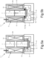
- the Fig. 5a shows in a schematic longitudinal section a known solenoid valve 1.1 in a de-energized state of the electromagnetic coil 3, and the Fig. 5b shows this solenoid valve 1.1 in the energized state of the coil 3.
- Such solenoid valves can, for example, be arranged in a hydraulic or pneumatic circuit for controlling the gearshift of an automated manual transmission.
- this known solenoid valve 1.1 has an electromagnetic coil 3 arranged in a valve housing 2 with a core 4 made of a soft magnetic material, an armature 5 made of a magnetic material and a winding 6 consisting of a copper wire.
- a valve inlet opening 7 is formed in the valve housing 2, which can be connected, for example, to a pneumatic or hydraulic supply pressure line.
- a valve outlet opening 8 is formed in the valve housing 2, which can be connected, for example, to a pneumatic or hydraulic control pressure line.
- the known solenoid valve 1.1 is designed as a monostable solenoid valve.
- the core 4 and the armature 5 of the solenoid valve 1.1 are arranged in the valve housing 2 radially inside the coil 6 and coaxially to a coil longitudinal axis 9.
- the armature 5 is arranged to be movable coaxially to the coil longitudinal axis 9, while the core 4 is attached to a housing part 2a in relation to the armature 5.
- Another component of the solenoid valve 1.1 is a sleeve-shaped coil carrier 10 in which the core 4 is at least partially placed and the armature 5 is guided to be movable coaxially.
- the winding 6 of the coil 3 is wound radially on the outside of the coil carrier 10 and has an electrical connection 11.
- the coil carrier 10 and the winding 6 of the coil 3 are surrounded radially on the outside by the aforementioned housing part 2a.
- the armature 5 is connected to a support plate 12 at the end and axially outside the coil carrier 10.
- An elastic valve closing element 13 is attached to the side of this support plate 12 remote from the armature, by means of which the coaxial valve inlet opening 7 remote from the armature can be sealed in a first setting position and released in a second setting position.
- the valve closing element 13 is placed against a valve seat 14 of the valve inlet opening 8 or it is arranged raised from this valve seat 14.
- the Fig. 5a shows the closed position of the solenoid valve 1.1, in which the movable armature 5 has a maximum axial distance from the core 4 and the valve closing element 13 is in sealing contact with the valve seat 14 of the valve inlet opening 7.
- the Fig. 5a shown closed position by means of the spring force of a return device 15 for the movable armature 5 in the form of a helical compression spring formed return spring 15a.
- the return spring 15a surrounds the armature 5 coaxially and is supported on the one hand via the coil carrier 10 on the housing part 2a of the valve housing 2 and on the other hand on the support plate 12 connected to the armature 5.
- the Fig. 5b shows the open position of the known solenoid valve 1.1.
- the coil 3 is energized, as a result of which the armature 5 lifts off the valve seat 14 and is moved towards the core 4.
- a medium for example compressed air, can then flow through the solenoid valve 1.1 via the ventilation path 16.
- the core 4 made of a soft magnetic material centers and strengthens the magnetic field generated by the coil 3, in such a way that the electromagnetic attraction force is stronger than the mechanical restoring force of the return spring 15a. If the current supply to the coil 3 is switched off, the armature 5 moves back to its closed position due to the force exerted by the return spring 15, after which the ventilation path 16 of the solenoid valve 1.1 is closed.
- the invention was based on the task of proposing a solenoid valve that is reliable, durable and also cost-effective to manufacture.
- a solenoid valve should be suitable for use in a switching system of a transmission in the drive train of a vehicle.
- the invention relates to a solenoid valve with a valve housing, at least one electromagnetic coil which has a coil carrier connected to the valve housing and an electrically conductive winding arranged on the coil carrier, at least one immovably arranged ferromagnetic core, an armature movably arranged within the coil coaxially to the coil longitudinal axis, a valve inlet opening formed on the valve housing with a valve seat, a valve outlet opening formed on the valve housing, and with a valve closing element connected to the armature, wherein at least the valve inlet opening can be closed pressure-tight by the valve closing element and the valve seat, and with a return device which loads the armature and the valve closing element in the closing direction or in the opening direction.
- this solenoid valve is provided with the reset device having at least two permanent magnets, a first permanent magnet being firmly connected to the core, a second permanent magnet being firmly connected to the armature, the two permanent magnets being arranged in such a way that a permanent magnetic force is effective between the core and the armature, by means of which the armature can be moved into a closed position or into an open position and held there in the de-energized state of the coil, and the armature can be moved out of the closed position or the open position in the energized state of the coil by an electromagnetic force of the coil which is greater than the permanent magnetic force effective between the core and the armature.
- the invention solves the technical problem mentioned at the beginning in a surprisingly simple way by means of a solenoid valve with a reset device which, unlike the design that has been common for many decades, does not have a return spring.
- the reset function is achieved according to the invention by a targeted arrangement of two permanent magnets.
- the invention makes use of the effect that that two permanent magnets repel each other when two similar poles, i.e. north pole and north pole or south pole and south pole, of the two permanent magnets are opposite each other, or attract each other when two dissimilar poles, i.e. north pole and south pole, are opposite each other.
- a first permanent magnet is arranged on the movable armature of the solenoid valve and a second permanent magnet with opposite magnetic orientations is arranged on the stationary core
- the movable armature is repelled by the permanent magnet arranged on the core and is thereby held in a defined rest position.
- the electromagnetic coil can be energized to generate an electromagnetic force which counteracts the permanent magnetic force between the armature and the core and is greater than this. The armature can therefore be moved out of the aforementioned rest position.
- the solenoid valve can be designed as a valve that is closed in the rest position (NC type) or a valve that is open in the rest position (NO type). This can be achieved by aligning the magnetic poles of the two permanent magnets accordingly.
- the reset device according to the invention has the advantage that it has no mechanical components, in particular no spring, which could be destroyed by frequent switching operations and/or external mechanical loads. This ensures a high level of operational reliability and durability of the solenoid valve, even under heavy use.
- the two permanent magnets require less installation space than a conventional return spring. This enables a very compact design of the solenoid valve.
- the solenoid valve is designed as a monostable solenoid valve, that the first permanent magnet is arranged on the end face of the core facing the armature, that the second permanent magnet is arranged on the end face of the armature facing the core, that the two permanent magnets are arranged coaxially to one another in such a way that two identical magnetic poles face one another, which generate a permanent magnetic repulsive force that repels the movable armature from the immobile core, that the armature is held in its closed position by the permanent magnetic repulsive force when the coil is de-energized, and that the armature is held in its closed position by an electromagnetic Attractive force of the coil, overcoming the permanent magnetic repulsion force, can be moved from the closed position to an open position.
- the solenoid valve can be designed as a monostable 2/2-way valve, which is closed in its rest position, i.e. when the coil is not energized.
- the positioning of the movable armature in its closed position is achieved by the mutual repulsion of the two permanent magnets. Since the core of the solenoid valve is immobile, the permanent magnetic repulsion force of the two permanent magnets presses the movable armature with its valve closing element against the valve seat of the valve housing, thereby closing the solenoid valve.
- the solenoid valve By energizing the coil, an electromagnetic force is exerted on the armature which is greater than the permanent magnetic repulsion force of the two permanent magnets. Therefore, when the coil is energized, the armature is moved towards the core, which opens the solenoid valve. As a result, a medium, such as compressed air, can flow via the valve inlet opening, through the valve housing and the valve outlet opening.
- the components of the solenoid valve namely the electromagnetic coil, the core, the armature and the two permanent magnets, are coordinated with one another in terms of their arrangement and properties in such a way that when the coil is energized, an electromagnetic force of attraction is generated which overcomes the permanent magnetic repulsion force, causing the armature to lift off the valve seat. As soon as the power to the coil is switched off, the armature returns to its rest position or to the closed position of the armature due to the repulsion force of the two permanent magnets.
- the solenoid valve is also designed as a monostable solenoid valve, but the immovable core has a first vent opening, that this first vent opening is designed as a continuous axial bore in the immovable core and in the first permanent magnet connected to the core, that in the closed position of the armature the first vent opening in the core is fluidically connected to the valve outlet opening in the valve housing, and that in the open position of the armature this first vent opening is blocked off.
- the solenoid valve can be designed as a monostable 3/2-way valve which is closed in its rest position, i.e. when the coil is not energized.
- the solenoid valve has a vent path which is open in the closed state, whereby the valve outlet opening or a pressure output line connected to it is depressurized.
- the permanent magnet attached to the core can be ring-shaped, through whose opening the vent path leads. This creates a vent device on a solenoid valve with the basic features of the invention in a comparatively simple manner.
- the permanent magnet of the armature closes the opening in the permanent magnet of the core.
- a sealing ring is arranged on the front side of the armature and/or the core.
- a solenoid valve designed according to the invention can be designed such that it is also designed as a monostable solenoid valve, that a second vent opening is designed in the valve housing, that the second vent opening is designed as a radial bore in the valve housing, that a bidirectionally effective valve closing element and a bidirectionally effective valve seat are present, that in the closed position of the armature the second vent opening in the valve housing is fluidically connected to the valve outlet opening, and that in the open position of the armature this vent opening is blocked off.
- the core does not have a vent hole. Instead, a vent outlet is formed by a radial hole in the valve housing.
- a second valve seat section is formed on the valve housing, which is formed coaxially opposite the first valve seat section. Both valve seat sections together form, by definition, a bidirectionally effective valve seat. Accordingly, this solenoid valve has a bidirectionally effective valve closing element, which has a first valve closing element section and a second valve closing element section coaxially opposite.
- the first valve closing element section When the armature is positioned in its closed position, the first valve closing element section rests with its side remote from the armature on the first valve seat section of the Valve inlet opening and thereby blocks it.
- the radial vent outlet is open when the armature is in this closed position and is therefore fluidically connected to the valve outlet opening.
- the second valve closing element section When the armature is in its open position, the second valve closing element section rests with its side closest to the armature on the second valve seat section and thereby blocks the radial vent outlet while the valve inlet opening is open. This means that the valve inlet opening is fluidically connected to the valve outlet opening.
- the armature is connected to an elongated connecting piece on its end face remote from the core, that the connecting piece extends coaxially to the longitudinal axis of the coil and penetrates an opening in the valve housing in a sealed manner, that the connecting piece is connected to a support plate on its end remote from the armature, that the bidirectional valve closing element is fastened to the support plate, that the bidirectional valve closing element has the first valve closing element section on its end face remote from the armature and the second valve closing element section on its end face close to the armature, that the first valve closing element section can be placed on the first valve seat section in a sealing manner against the valve inlet opening, and that the second valve closing element section can be placed on the second valve seat section in a sealing manner against the radial vent opening.
- the invention is designed for monostable solenoid valves, i.e. for valves with exactly one defined rest position of the movable armature when the coil is de-energized, but is not limited to this.
- the structure of a solenoid valve according to the invention can also be used advantageously on bistable solenoid valves, i.e. on solenoid valves with two defined rest positions of the movable armature when the coil is de-energized.
- bistable solenoid valves i.e. on solenoid valves with two defined rest positions of the movable armature when the coil is de-energized.
- two permanent magnet devices with two permanent magnets each can be used according to the teaching of the invention in order to implement a bidirectionally effective reset function.
- the electromagnetic coil in both monostable solenoid valves and bistable solenoid valves can be designed as a single piece with one winding and one electrical connection, or as a multi-piece with two windings and two electrical connections.
- a permanent magnet device according to the invention with an additional mechanical return spring are also possible, which work together in a return device of a solenoid valve.
- the mechanical spring can be designed to be weaker and smaller than a conventional return spring, since the latter is supported in its function by the permanent magnet device according to the invention. It is only important that at least two permanent magnets are arranged opposite one another on the movable armature and on at least one fixed core of the solenoid valve in such a way that their permanent magnet force provides an independent return force for the armature, which does not necessarily require a mechanical spring.
- the invention also relates to a transmission switching system of an automated manual transmission for a vehicle, such as a commercial vehicle or a passenger car, with at least one solenoid valve, which is constructed according to one of the device claims.
- the prior art solenoid valve 1.1 shown in Figures 1-4 has already been described above.
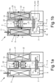
- the solenoid valve 1.1 shown in Figures 1-4 has Fig. 1a and 1b
- the solenoid valve 1 according to the invention shown in FIG. 1 has a reset device 20 which is designed as an arrangement of permanent magnets.
- a conventional reset device 15 with a return spring 15a, as described above, is therefore not present.
- the reset device 20 shown has, according to the invention, a first permanent magnet 21 and a second permanent magnet 22.
- the first permanent magnet 21 is arranged on the end face of the stationary core 4 facing the armature 5 and is connected to the core 4.
- the second permanent magnet 22 is arranged on the end face of the axially movable armature 5 facing the core 4 and is connected to the armature 5.
- the two permanent magnets 21, 22 are arranged coaxially to one another and aligned in such a way that the magnetic field lines of their magnetic fields 23, 24 each run between the magnetic north pole N and the magnetic south pole S approximately coaxially to the coil longitudinal axis 9, with two similar magnetic poles, in this case for example the first north pole N and the second north pole N, facing one another. Consequently, the movable armature 5 is repelled by a permanent magnetic repulsion force from the stationary core 4 and pushed axially in the direction of the valve inlet opening 7 until a valve closing element 13, which is arranged on the opposite other end face of the armature 5, rests against the valve seat 14 and closes the valve inlet opening 7.
- the Figures 1a to 4b The support plate 12 shown here does not serve as an abutment for a return spring, but as a fastening adapter for the respective sealing valve closing element 13, 44.
- the Fig. 1a shows the solenoid valve 1 in its closed position, in which the movable armature 5 has a maximum axial distance from the core 4, and the valve closing element 13 rests against the valve seat 14 of the valve inlet opening 7 due to the permanent magnetic repulsion between the stationary core 4 or the first permanent magnet 21 and the movable armature 5 or the second permanent magnet 22.
- the solenoid valve 1 is designed as a 2/2-way valve and of the NC type, which is closed when the coil 3 is de-energized. Accordingly, the valve inlet opening 7 is blocked when the solenoid valve 1 is not actuated.
- the Fig. 1b shows the open position of the solenoid valve 1.
- the electric coil 3 was energized.
- the coil 3 generated a magnetic field 25, which generated an attractive force in the core 4, which moved the armature 5 in the direction of the core 4.
- the armature 5 performed a stroke H in the direction of the core 4, whereby the valve inlet opening 7 was opened.
- a fluid can flow through the valve housing 2 via the ventilation path 16 shown and a fluid pressure can be available at the valve outlet opening 8.
- the Fig. 1b In the open position H_min of the armature 5 shown in the figure, the armature 5 has its smallest distance to the core 4.
- the position of the closed position H_max of the armature 5, which is also shown, has, as shown in the Fig. 1a shows its maximum distance from core 4.
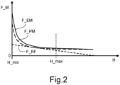
- the Fig.2 shows the course of the electromagnetic force F_EM and the course of the permanent magnetic force F_PM as a function of the valve stroke H of the solenoid valve 1.
- the Fig. 1a shows, in the closed position H_max of the armature 5 only the permanent magnetic restoring force of the restoring device 20 acts on the armature 5 and presses it against the valve seat 14.
- the electromagnetic force F_EM counteracts the permanent magnetic force F_PM and dominates over the latter.
- the armature 5 begins to lift off from the valve seat 14 because the electromagnetic attraction predominates.
- the repulsive permanent magnetic force F_PM of the restoring device 20 increases exponentially.
- the curve of the attractive electromagnetic force F_EM runs approximately parallel to the repulsive permanent magnetic force F_PM, but is always slightly above the permanent magnetic force F_PM. Accordingly, the attractive force on the armature 5 towards the core 4 predominates and the armature 5 finally reaches its smallest distance from the core 4 in the open position H_min, whereby the armature 5 according to Fig. 1b to the core 4.
- the armature 5 moves back to its closed position H_max, in which the solenoid valve 1 is closed, due to the force exerted by the permanent magnetic reset device 20.
- the armature 5 has Fig. 1a his maximum distance from the core 4.
- Fig.2 also the course of the restoring force F_RF of a conventional return spring 15a according to Fig. 5a and Fig. 5b which depends linearly on the deflection of the spring.
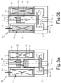
- Fig. 3a and Fig.3b show a second embodiment of a solenoid valve 30 with the features of the invention.
- This solenoid valve 30 is designed as a 3/2-way valve and has a first vent opening 31 for venting the solenoid valve 30 or for venting a pressure line connected to the valve outlet opening 8 when the solenoid valve 30 is not actuated.
- the vent opening 31 is designed as a continuous axial bore in the core 4 of the solenoid valve 30.
- the vent opening 31 is also guided coaxially through an annular first permanent magnet 32 connected to the core 4.
- a sleeve-shaped flow path 47 is formed between the radial outside of the armature 5 and the radial inside of the coil carrier 10, via which the valve outlet opening 8 and the first vent opening 31 are fluidically connected to one another.
- this second solenoid valve 30 is constructed in the same way as the first solenoid valve 1 according to the Figures 1a and 1b .
- the armature 5 In the closed position of the solenoid valve 30, the armature 5 is in accordance with Fig. 3a arranged axially spaced from the core 4.
- a vent path 33 is open between the valve outlet opening 8 and the vent opening 31, whereby a fluid can escape to the outside and a fluid pressure can be reduced.
- the ventilation path 16 is open and the vent path 33 is blocked, since the armature 5 then rests against the core 4 and closes the vent opening 31.
- Fig. 4a and Fig.4b show in a further embodiment a third solenoid valve 40, which has the features of the invention, but a different vent opening 41 than in the embodiment according to the Figures 3a and 3b
- This alternative vent opening 41 is designed as a radial bore in the valve housing 2*.
- the axially movable armature 42 has a rod-shaped axial connecting piece 43 which penetrates an opening in the valve housing 2* in a sealed manner and to whose end near the valve seat a bidirectionally effective valve closing element 44 is attached.
- the bidirectional valve closing element 44 is connected to a support plate 12 which is attached to the connecting piece 43.
- This bidirectional valve closing element 44 has a first valve closing element section 44a and a second valve closing element section 44b.
- the first valve closing element section 44a is arranged on the side of the support plate 12 connected to the connecting piece 43 facing away from the armature 5.
- the second valve closing element section 44b is arranged on the side of the support plate 12 facing the armature 5.
- a bidirectionally effective valve seat 45 is formed in the valve housing 2, which interacts with the bidirectional valve closing element 44.
- the bidirectional valve seat 45 has a first valve seat section 45a and a second valve seat section 45b.
- the first valve seat section 45a is formed remote from the armature in the valve housing 2* and is assigned to the valve inlet opening 7.
- the second valve seat section 45b is formed close to the armature in the valve housing 2* and is assigned to the radial vent opening 41.
- valve inlet opening 7 In the in the Fig. 4a In the closed position of the unactuated third solenoid valve 40 shown in the figure, the valve inlet opening 7 is blocked. At the same time, a vent path 46 between the valve outlet opening 8 and the outlet of the second vent opening 41 is open. In the position shown in the Fig. 4b In the open position of the actuated solenoid valve 40 shown, the valve inlet opening 7 is open and the ventilation path 16 is released. At the same time, the ventilation path 46 between the valve outlet opening 8 and the outlet of the ventilation opening 41 is blocked.
Landscapes
- Engineering & Computer Science (AREA)
- General Engineering & Computer Science (AREA)
- Mechanical Engineering (AREA)
- Physics & Mathematics (AREA)
- Electromagnetism (AREA)
- Magnetically Actuated Valves (AREA)
Abstract
Die Erfindung betrifft ein Magnetventil (1), mit einem Ventilgehäuse (2), mindestens einer elektromagnetischen Spule (3), welche einen mit dem Ventilgehäuse verbundenen Spulenträger (10) und eine an dem Spulenträger angeordnete elektrisch leitende Wicklung (6) aufweist, mindestens einem unbeweglich angeordneten ferromagnetischen Kern (4), einem innerhalb der Spule koaxial zur Spulenlängsachse (9) beweglich angeordneten Anker (5), einer am Ventilgehäuse ausgebildeten Ventileinlassöffnung (7) mit einem Ventilsitz (14), einer am Ventilgehäuse ausgebildeten Ventilauslassöffnung (8), und mit einem mit dem Anker (5) verbundenen Ventilschließelement (13), wobei zumindest die Ventileinlassöffnung (7) durch das Ventilschließelement (13) und den Ventilsitz (14) druckdicht verschließbar ist, sowie mit einer den Anker (5) und das Ventilschließelement in Schließrichtung oder in Öffnungsrichtung belastenden Rückstelleinrichtung.
Description
- Die Erfindung betrifft ein Magnetventil mit einem Ventilgehäuse, mit mindestens einer elektromagnetischen Spule, welche einen mit dem Ventilgehäuse verbundenen Spulenträger und eine an dem Spulenträger angeordnete elektrisch leitende Wicklung aufweist, mit mindestens einem unbeweglich angeordneten ferromagnetischen Kern, einem innerhalb der Spule koaxial zur Spulenlängsachse beweglich angeordneten Anker, eine am Ventilgehäuse ausgebildete Ventileinlassöffnung mit einem Ventilsitz, eine am Ventilgehäuse ausgebildete Ventilauslassöffnung, und mit einem mit dem Anker verbundenen Ventilschließelement, wobei zumindest die Ventileinlassöffnung durch das Ventilschließelement und den Ventilsitz druckdicht verschließbar ist, sowie mit einer den Anker und das Ventilschließelement in Schließrichtung oder in Öffnungsrichtung belastenden Rückstelleinrichtung.
- Derartige Magnetventile sind in verschiedenen Ausführungsformen für eine Vielzahl von Anwendungen bekannt, beispielsweise zur Betätigung von Schaltvorrichtungen in automatisierten Schaltgetrieben von Kraftfahrzeugen. Die
DE 10 2008 047 981 A1 und dieDE 10 2019 133 007 A1 zeigen Ausführungsbeispiele von derartigen Magnetventilen, welche für Anwendungen in einem Kraftfahrzeug vorgesehen sind. Bei den bekannten Magnetventilen weist eine dort ausgebildete Rückstelleinrichtung meistens eine mechanische Rückstellfeder auf, welche den Anker in einer ersten Stellposition festhält. Die elektromagnetische Spule erzeugt bei deren Bestromung ein Magnetfeld, die auf den Anker eine Magnetkraft ausübt, welche der Federkraft der Rückstellfeder entgegenwirkt und diese überwiegt, wodurch der Anker aus der ersten Stellposition hin zu einer zweiten Stellposition bewegt und dort festgehalten wird. Nach dem Ausschalten der Bestromung der Spule kehrt der Anker durch die Federkraft der Rückstellfeder wieder in seine Ausgangslage zurück. - Die
Fig. 5a zeigt in einem schematischen Längsschnitt ein bekanntes Magnetventil 1.1 in einem unbestromten Zustand der elektromagnetischen Spule 3, und dieFig. 5b zeigt dieses Magnetventil 1.1 im bestromten Zustand der Spule 3. Derartige Magnetventile können beispielswiese in einem hydraulischen oder pneumatischen Schaltkreis zur Schaltsteuerung eines automatisierten Schaltgetriebes angeordnet sein. - Wie die
Figuren 5a und 5b veranschaulichen, weist dieses bekannte Magnetventil 1.1 eine in einem Ventilgehäuse 2 angeordnete elektromagnetische Spule 3 mit einem Kern 4 aus einem weichmagnetischen Werkstoff, einen Anker 5 aus einem magnetischen Werkstoff sowie eine Wicklung 6 auf, welche aus einem Kupferdraht besteht. In dem Ventilgehäuse 2 ist eine Ventileinlassöffnung 7 ausgebildet, welche beispielweise mit einer pneumatischen oder hydraulischen Versorgungsdruckleitung verbunden sein kann. Außerdem ist in dem Ventilgehäuse 2 eine Ventilauslassöffnung 8 ausgebildet, welche beispielsweise mit einer pneumatischen oder hydraulischen Steuerdruckleitung verbunden sein kann. - Das bekannte Magnetventil 1.1 ist als ein monostabiles Magnetventil ausgebildet. Der Kern 4 und der Anker 5 des Magnetventils 1.1 sind in dem Ventilgehäuse 2 radial innerhalb der Spule 6 sowie koaxial zu einer Spulenlängsachse 9 angeordnet. Der Anker 5 ist koaxial zur Spulenlängsachse 9 beweglich angeordnet, während der Kern 4 in Bezug zum Anker 5 an einem Gehäuseteil 2a befestigt ist. Ein weiterer Bestandteil des Magnetventils 1.1 ist ein hülsenförmiger Spulenträger 10, in dem der Kern 4 zumindest teilweise platziert und der Anker 5 koaxial beweglich geführt ist. Die Wicklung 6 der Spule 3 ist radial außen auf dem Spulenträger 10 aufgewickelt und weist einen elektrischen Anschluss 11 auf. Der Spulenträger 10 und die Wicklung 6 der Spule 3 sind radial außen von dem erwähnten Gehäuseteil 2a umgeben. Der Anker 5 ist endseitig und axial außerhalb des Spulenträgers 10 mit einer Stützplatte 12 verbunden. Auf der ankerfernen Seite dieser Stützplatte 12 ist ein elastisches Ventilschließelement 13 befestigt, mittels dem die ankerfern ausgebildete koaxiale Ventileinlassöffnung 7 in einer ersten Stellposition abdichten und in einer zweiten Stellposition freigeben werden kann. Hierzu ist das Ventilschließelement 13 an einen Ventilsitz 14 der Ventileinlassöffnung 8 angelegt oder es ist von diesem Ventilsitz 14 abgehoben angeordnet.
- Die
Fig. 5a zeigt die Schließstellung des Magnetventils 1.1, in welcher der bewegliche Anker 5 zu dem Kern 4 einen axial maximalen Abstand aufweist und das Ventilschließelement 13 an dem Ventilsitz 14 der Ventileinlassöffnung 7 diese abdichtend anliegt. Erreicht wird die inFig. 5a dargestellte Schließstellung mittels der Federkraft einer Rückstelleinrichtung 15 für den beweglichen Anker 5 in Form einer als Schraubendruckfeder ausgebildeten Rückstellfeder 15a. Die Rückstellfeder 15a umgreift den Anker 5 koaxial und stützt sich einerseits über den Spulenträger 10 an dem Gehäuseteil 2a des Ventilgehäuses 2 und andererseits an der mit dem Anker 5 verbundenen Stützplatte 12 ab. - Das Magnetventil 1.1 ist dementsprechend vom NC-Typ (NC = normally closed), bei dem im stromlosen Zustand der Spule 3 ein Belüftungspfad 16 zwischen einem Anschluss für ein unter Druck stehendes Fluid, also der Ventileinlassöffnung 7, und einem Arbeitsanschluss, also der Ventilauslassöffnung 8, versperrt ist.
- Die
Fig. 5b zeigt die Offenstellung des bekannten Magnetventils 1.1. Um diese Offenstellung einzustellen wird die Spule 3 bestromt, in deren Folge der Anker 5 vom Ventilsitz 14 abhebt und hin zum Kern 4 bewegt wird. Sodann kann ein Medium, beispielsweise Druckluft, über den Belüftungspfad 16 durch das Magnetventil 1.1 hindurchströmen. Bei der Bestromung der Spule 3 bewirkt der Kern 4 aus einem weichmagnetischen Werkstoff eine Zentrierung und Verstärkung des durch die Spule 3 erzeugten Magnetfeldes, und zwar derart, dass die elektromagnetische Anziehungskraft stärker ist als die mechanische Rückstellkraft der Rückstellfeder 15a. Wird die Bestromung der Spule 3 abgeschaltet, so bewegt sich der Anker 5 durch die Kraftausübung der Rückstellfeder 15 wieder zurück zu seiner Schließstellung, nach deren Erreichen der Belüftungspfad 16 des Magnetventils 1.1 geschlossen ist. - Die bekannten Magnetventile mit einer Rückstelleinrichtung für einen beweglichen Anker in Form einer Rückstellfeder haben sich seit langem vielfach bewährt. Allerdings sind bei besonders beanspruchten Magnetventilen der eingangs genannten Bauart, insbesondere im Bereich von modernen automatisierten Schaltgetrieben von Kraftfahrzeugen, Ventilversagen festgestellt worden, welche auf einen Bruch der Rückstellfeder zurückzuführen sind. Um das Risiko eines Federbruchs zu verhindern, sind daher bei Magnetventilen, welche hohen Beschleunigungskräften und großen Betätigungszahlen ausgesetzt sind, zusätzliche Maßnahmen, wie eine Schmiermittelversorgung und/oder eine verstärkte Feder erforderlich. Dadurch entstehen höhere Herstellungskosten. Zudem ist der für die Anordnung einer Rückstellfeder verfügbare Bauraum begrenzt.
- Vor diesem Hintergrund lag der Erfindung die Aufgabe zugrunde, ein Magnetventil vorzuschlagen, das betriebssicher, langlebig und zudem kostengünstig in der Herstellung ist. Insbesondere soll ein solches Magnetventil für den Einsatz in einem Schaltsystem eines Getriebes im Antriebsstrang eines Fahrzeugs geeignet sein.
- Die Lösung dieser Aufgabe wird mit einem Magnetventil erreicht, welches die Merkmale des unabhängigen Anspruchs aufweist. Vorteilhafte Ausgestaltungen und Weiterbildungen der Erfindung in den abhängigen Ansprüchen definiert.
- Demnach betrifft die Erfindung ein Magnetventil mit einem Ventilgehäuse, mindestens einer elektromagnetischen Spule, welche einen mit dem Ventilgehäuse verbundenen Spulenträger und eine an dem Spulenträger angeordnete elektrisch leitende Wicklung aufweist, mindestens einem unbeweglich angeordneten ferromagnetischen Kern, einem innerhalb der Spule koaxial zur Spulenlängsachse beweglich angeordneten Anker, einer am Ventilgehäuse ausgebildeten Ventileinlassöffnung mit einem Ventilsitz, einer am Ventilgehäuse ausgebildeten Ventilauslassöffnung, und mit einem mit dem Anker verbundenen Ventilschließelement, wobei zumindest die Ventileinlassöffnung durch das Ventilschließelement und den Ventilsitz druckdicht verschließbar ist, sowie mit einer den Anker und das Ventilschließelement in Schließrichtung oder in Öffnungsrichtung belastenden Rückstelleinrichtung.
- Zur Lösung der gestellten Aufgabe ist bei diesem Magnetventil vorgesehen, dass die Rückstelleinrichtung mindestens zwei Permanentmagnete aufweist, dass ein erster Permanentmagnet mit dem Kern fest verbunden ist, dass ein zweiter Permanentmagnet mit dem Anker fest verbunden ist, dass die beiden Permanentmagnete derart angeordnet sind, dass eine Permanentmagnetkraft zwischen dem Kern und dem Anker wirksam ist, mittels welcher der Anker im unbestromten Zustand der Spule in eine Schließstellung oder in eine Offenstellung bewegbar und dort festhaltbar ist, und dass der Anker im bestromten Zustand der Spule durch eine Elektromagnetkraft der Spule, welche größer ist als die zwischen dem Kern und dem Anker wirksame Permanentmagnetkraft, aus der Schließstellung oder der Offenstellung herausbewegbar ist.
- Die Erfindung löst das eingangs erwähnte technische Problem auf überraschend einfache Weise durch ein Magnetventil mit einer Rückstelleinrichtung, welche abweichend von der seit vielen Jahrzehnten üblichen Konstruktion auf eine Rückstellfeder verzichtet. Die Rückstellfunktion wird erfindungsgemäß durch eine zielgerichtete Anordnung von zwei Permanentmagneten erreicht. Die Erfindung macht sich dabei den Effekt zu Nutze, dass sich zwei Permanentmagnete abstoßen, wenn sich zwei gleichartige Pole, also Nordpol und Nordpol oder Südpol und Südpol, der beiden Permanentmagnete gegenüberstehen, beziehungsweise sich anziehen, wenn sich zwei ungleichartige Pole, also Nordpol und Südpol, gegenüberstehen. Dadurch, dass an dem beweglichen Anker des Magnetventils ein erster Permanentmagnet und an dem ortsfesten Kern ein zweiter Permanentmagnet mit zueinander entgegengesetzten magnetischen Ausrichtungen angeordnet sind, wird der bewegliche Anker von dem am Kern angeordneten Permanentmagneten abgestoßen und dadurch in einer definierten Ruheposition gehalten. Die elektromagnetische Spule kann bestromt werden, um eine elektromagnetische Kraft zu erzeugen, welche der permanentmagnetischen Kraft zwischen dem Anker und dem Kern entgegenwirkt und größer ist als diese. Dadurch kann der Anker aus der erwähnten Ruheposition heraus bewegt werden.
- Das Magnetventil kann je nach Anforderung als in Ruhestellung geschlossenes Ventil (NC-Typ) oder in Ruhestellung geöffnetes Ventil (NO-Typ) ausgebildet sein. Dies kann durch eine entsprechende Ausrichtung der Magnetpole der beiden Permanentmagnete zueinander erreicht werden. Die Rückstelleinrichtung gemäß der Erfindung hat den Vorteil, dass sie keine mechanischen Bauelemente, insbesondere keine Feder aufweist, welche durch häufige Schaltvorgänge und/oder äußere mechanische Belastungen zerstört werden könnten. Dadurch wird eine hohe Betriebssicherheit und Langlebigkeit des Magnetventils auch bei starker Beanspruchung erreicht. Die beiden Permanentmagnete benötigen einen kleineren Einbauraum als eine herkömmliche Rückstellfeder. Dadurch ist eine sehr kompakte Bauform des Magnetventils erreichbar.
- Gemäß einer ersten Weiterbildung der Erfindung kann vorgesehen sein, dass das Magnetventil als ein monostabiles Magnetventil ausgebildet ist, dass der erste Permanentmagnet an der dem Anker zugewandten Stirnseite des Kerns angeordnet ist, dass der zweite Permanentmagnet an der dem Kern zugewandten Stirnseite des Ankers angeordnet ist, dass die beiden Permanentmagnete derart koaxial zueinander angeordnet sind, dass zwei gleichartige Magnetpole einander zugewandt sind, welche eine permanentmagnetische Abstoßungskraft erzeugen, die den beweglichen Anker von dem unbeweglichen Kern abstößt, dass der Anker im unbestromten Zustand der Spule durch die permanentmagnetische Abstoßungskraft in seiner Schließstellung festgehalten wird, und dass der Anker im bestromten Zustand der Spule durch eine elektromagnetische Anziehungskraft der Spule, die permanentmagnetische Abstoßungskraft überwindend, aus der Schließstellung in eine Offenstellung bewegbar ist.
- Demnach kann das Magnetventil als ein monostabiles 2/2-Wegeventil ausgebildet sein, welches in dessen Ruhestellung, also im unbestromten Zustand der Spule, geschlossen ist. Die Positionierung des beweglichen Ankers in seiner Schließstellung wird durch die gegenseitige Abstoßung der beiden Permanentmagnete erreicht. Da bei dem Magnetventil der Kern unbeweglich angeordnet ist, wird der bewegliche Anker durch die permanentmagnetische Abstoßungskraft der beiden Permanentmagnete mit seinem Ventilschließelement gegen den Ventilsitz des Ventilgehäuses gedrückt und dadurch das Magnetventil geschlossen.
- Durch Bestromen der Spule wird eine elektromagnetische Kraft auf den Anker ausgeübt, welche größer ist als die permanentmagnetische Abstoßungskraft der beiden Permanentmagnete. Daher wird Anker bei bestromter Spule in Richtung zum Kern bewegt, wodurch das Magnetventil geöffnet wird. In dessen Folge kann ein Medium, beispielsweise Druckluft, über die Ventileinlassöffnung durch das Ventilgehäuse und die Ventilauslassöffnung hindurchströmen. Die Komponenten des Magnetventils, nämlich die elektromagnetische Spule, der Kern, der Anker sowie die beiden Permanentmagneten sind hinsichtlich deren Anordnung und Eigenschaften derart aufeinander abgestimmt, dass bei einer Bestromung der Spule eine elektromagnetische Anziehungskraft erzeugt wird, welche die permanentmagnetische Abstoßungskraft überwindet, wodurch der Anker von dem Ventilsitz abhebt. Sobald die Bestromung der Spule abgeschaltet wird, kehrt der Anker durch die Abstoßungskraft der beiden Permanentmagnete in seine Ruheposition beziehungsweise in die Schließstellung des Ankers zurück.
- Gemäß einer zweiten Weiterbildung der Erfindung ist vorgesehen, dass das Magnetventil ebenfalls als ein monostabiles Magnetventil ausgebildet ist, wobei der unbewegliche Kern jedoch eine erste Entlüftungsöffnung aufweist, dass diese erste Entlüftungsöffnung als eine durchgehende Axialbohrung in dem unbeweglichen Kern sowie in dem mit dem Kern verbundenen ersten Permanentmagneten ausgebildet ist, dass in der Schließstellung des Ankers die erste Entlüftungsöffnung in dem Kern mit der Ventilauslassöffnung im Ventilgehäuse strömungstechnisch verbunden ist, und dass in der Offenstellung des Ankers diese erste Entlüftungsöffnung abgesperrt ist.
- Demnach kann das Magnetventil als monostabiles 3/2-Wegeventil ausgebildet sein, welches in dessen Ruhestellung, also im unbestromten Zustand der Spule, geschlossen ist. Das Magnetventil weist einen im Schließzustand geöffneten Entlüftungspfad auf, wodurch die Ventilauslassöffnung beziehungsweise eine daran angeschlossene Druckausgangleitung drucklos geschaltet ist. Der am Kern befestigte Permanentmagnet kann ringförmig ausgebildet sein, durch dessen Öffnung der Entlüftungspfad hindurch führt. Dadurch ist vergleichsweise einfach eine Entlüftungseinrichtung an einem Magnetventil mit den grundlegenden Merkmalen der Erfindung geschaffen. Im geöffneten Zustand dieses Magnetventils, in welchem der Anker stirnseitig an dem Kern anliegt, verschließt der Permanentmagnet des Ankers die Öffnung im Permanentmagnet des Kerns. Um eine gute Abdichtwirkung zu erreichen kann vorgesehen sein, dass stirnseitig an dem Anker und/oder dem Kern ein Dichtring angeordnet ist.
- Alternativ zu der gerade erläuterten Ausführungsform kann bei einem erfindungsgemäß ausgebildeten Magnetventil vorgesehen sein, dass dieses ebenfalls als ein monostabiles Magnetventil ausgebildet ist, dass in dem Ventilgehäuse eine zweite Entlüftungsöffnung ausgebildet ist, dass die zweite Entlüftungsöffnung als eine Radialbohrung in dem Ventilgehäuse ausgebildet ist, dass ein bidirektional wirksames Ventilschließelement sowie ein bidirektional wirksamer Ventilsitz vorhanden sind, dass in der Schließstellung des Ankers die zweite Entlüftungsöffnung in dem Ventilgehäuse mit der Ventilauslassöffnung strömungstechnisch verbunden ist, und dass in der Offenstellung des Ankers diese Entlüftungsöffnung abgesperrt ist.
- Bei dieser Ausführungsform eines monostabiles 3/2-Wegeventil weist der Kern keine Entlüftungsbohrung auf. Vielmehr ist ein Entlüftungsausgang durch eine Radialbohrung in dem Ventilgehäuse gebildet. Außerdem ist an dem Ventilgehäuse ein zweiter Ventilsitzabschnitt ausgebildet, welcher koaxial gegenüber dem ersten Ventilsitzabschnitt ausgebildet ist. Beide Ventilsitzabschnitte bilden zusammen definitionsgemäß einen bidirektional wirksamen Ventilsitz. Dementsprechend ist bei diesem Magnetventil ein bidirektional wirksames Ventilschließelement vorhanden, welches einen ersten Ventilschließelementabschnitt und koaxial gegenüberliegend einen zweiten Ventilschlie-ßelementabschnitt aufweist.
- Wenn der Anker in seiner Schließstellung positioniert ist, liegt der erste Ventilschlie-ßelementabschnitt mit seiner ankerfernen Seite an dem ersten Ventilsitzabschnitt der Ventileinlassöffnung an und sperrt diese dadurch ab. Der radiale Entlüftungsausgang ist bei dieser Schließstellung des Ankers geöffnet und daher strömungstechnisch mit der Ventilauslassöffnung verbunden. Wenn sich der Anker in seiner Offenstellung befindet liegt der zweite Ventilschließelementabschnitt mit seiner ankernahen Seite an dem zweiten Ventilsitzabschnitt an und versperrt dadurch den radialen Entlüftungsausgang, während die Ventileinlassöffnung geöffnet ist. Hierdurch ist die Ventileinlassöffnung mit der Ventilauslassöffnung strömungstechnisch verbunden.
- Bei dieser Bauform des Magnetventils kann zusätzlich vorgesehen sein, dass der Anker an seiner vom Kern fernen Stirnseite mit einem langgestreckten Verbindungsstück verbunden ist, dass sich das Verbindungsstück koaxial zur Spulenlängsachse erstreckt und eine Öffnung im Ventilgehäuse abgedichtet durchdringt, dass das Verbindungsstück an seinem ankerfernen Ende mit einer Stützplatte verbunden ist, dass an der Stützplatte das bidirektionale Ventilschließelement befestigt ist, dass das bidirektionale Ventilschließelement an seiner ankerfernen Stirnseite den ersten Ventilschließelementabschnitt sowie an seiner ankernahen Stirnseite den zweiten Ventilschließelementabschnitt aufweist, dass der erste Ventilschließelementabschnitt an dem ersten Ventilsitzabschnitt die Ventileinlassöffnung abdichtend anlegbar ist, und dass der zweite Ventilschließelementabschnitt an dem zweiten Ventilsitzabschnitt die radiale Entlüftungsöffnung abdichtend anlegbar ist.
- Die Erfindung ist zwar für monostabile Magnetventile, also für Ventile mit genau einer definierten Ruhestellung des beweglichen Ankers im unbestromten Zustand der Spule konzipiert, aber nicht darauf beschränkt. Der erfindungsgemäße Aufbau eines Magnetventils kann ebenso vorteilhaft an bistabilen Magnetventilen genutzt werden, also an Magnetventilen mit zwei definierten Ruhestellungen des beweglichen Ankers im stromlosen Zustand der Spule. Dabei können beispielsweise zwei Permanentmagneteinrichtungen mit jeweils zwei Permanentmagneten gemäß der Lehre der Erfindung zum Einsatz kommen, um eine bidirektional wirksame Rückstellungsfunktion zu realisieren.
- Außerdem kann die elektromagnetische Spule sowohl bei monostabilen Magnetventilen als auch bei bistabilen Magnetventilen einteilig mit einer Wicklung sowie einem elektrischen Anschluss, oder mehrteilig mit zwei Wicklungen und zwei elektrischen Anschlüssen ausgebildet sein.
- Weiter sind auch Kombinationen einer Permanentmagneteinrichtung gemäß der Erfindung mit einer zusätzlichen mechanischen Rückstellfeder möglich, welche in einer Rückstelleinrichtung eines Magnetventils zusammenwirken. Die mechanische Feder kann in diesem Fall schwächer und kleiner ausgelegt sein als eine herkömmliche Rückstellfeder, da diese von der Permanentmagneteinrichtung gemäß der Erfindung in ihrer Funktion unterstützt wird. Wichtig ist lediglich, dass an dem beweglichen Anker und an zumindest einem feststehenden Kern des Magnetventils zumindest zwei Permanentmagnete derart gegenüberstehend angeordnet sind, dass mittels deren Permanentmagnetkraft eine eigenständige Rückstellkraft für den Anker verfügbar ist, welche keine mechanische Feder zwingend benötigt.
- Schließlich betrifft die Erfindung auch eine Getriebeschaltanlage eines automatisierten Schaltgetriebes für ein Fahrzeug, wie ein Nutzfahrzeug oder ein Personenkraftwagen, mit wenigstens einem Magnetventil, welches gemäß einem der Vorrichtungsansprüche aufgebaut ist.
- Die Erfindung wird nachstehend anhand von in der beigefügten Zeichnung dargestellten Ausführungsbeispielen näher erläutert. In der Zeichnung zeigt
-
Fig. 1a eine schematische Längsschnittdarstellung eines Magnetventils gemäß einer ersten Ausführungsform der Erfindung in dessen Schließstellung, -
Fig. 1b das Magnetventil gemäßFig. 1a in dessen Offenstellung, -
Fig. 2 ein Kraft-Weg-Diagramm eines Ventilhubs eines Magnetventils gemäß der Erfindung, im Vergleich zu einem Magnetventil gemäß dem Stand der Technik, -
Fig. 3a eine schematische Längsschnittdarstellung eines Magnetventils gemäß einer zweiten Ausführungsform der Erfindung in dessen Schließstellung, -
Fig. 3b das Magnetventil gemäßFig. 2a in dessen Offenstellung, -
Fig. 4a eine schematische Längsschnittdarstellung eines Magnetventils gemäß einer dritten Ausführungsform der Erfindung in dessen Schließstellung, -
Fig. 4b das Magnetventil gemäßFig. 3a in dessen Offenstellung, -
Fig. 5a eine schematische Längsschnittdarstellung eines Magnetventils gemäß dem Stand der Technik in dessen Schließstellung, und -
Fig. 5b das Magnetventil gemäßFig. 5a in dessen Offenstellung, - Einige Bauelemente in den Figuren stimmen überein, sodass diese mit denselben Bezugsziffern bezeichnet sind.
- Das in
Fig. 5a und Fig. 5b dargestellte Magnetventil 1.1 gemäß dem Stand der Technik ist bereits eingangs beschrieben worden. Im Unterschied zu dem bekannten Magnetventil 1.1 weist das in den FigurenFig. 1a und 1b dargestellte erfindungsgemäße Magnetventil 1 eine Rückstelleinrichtung 20 auf, welche als eine Anordnung von Permanentmagneten ausgebildet ist. Eine herkömmliche Rückstelleinrichtung 15 mit einer Rückstellfeder 15a, wie eingangs beschrieben, ist demnach nicht vorhanden. Die inFig. 1a und inFig. 1b gezeigte Rückstelleinrichtung 20 weist gemäß der Erfindung einen ersten Permanentmagnet 21 und einen zweiten Permanentmagnet 22 auf. Der erste Permanentmagnet 21 ist an der dem Anker 5 zugewandten Stirnseite des ortsfesten Kerns 4 angeordnet und mit dem Kern 4 verbunden. Der zweite Permanentmagnet 22 ist an der dem Kern 4 zugewandten Stirnseite des axial beweglichen Ankers 5 angeordnet und mit dem Anker 5 verbunden. - Die beiden Permanentmagnete 21, 22 sind koaxial zueinander angeordnet und so ausgerichtet, dass die Magnetfeldlinien ihrer Magnetfelder 23, 24 jeweils zwischen dem magnetischen Nordpol N und dem magnetischen Südpol S etwa koaxial zur Spulenlängsachse 9 verlaufen, wobei sich zwei gleichartige Magnetpole, vorliegend beispielsweise der erste Nordpol N und der zweite Nordpol N, zueinander gegenüberstehen. Folglich wird der bewegliche Anker 5 durch eine permanentmagnetische Abstoßungskraft von dem ortsfesten Kern 4 abgestoßen und soweit in Richtung zu der Ventileinlassöffnung 7 axial geschoben, bis ein Ventilschließelement 13, welches an der gegenüberliegenden anderen Stirnseite des Ankers 5 angeordnet ist, an dem Ventilsitz 14 anliegt und die Ventileinlassöffnung 7 verschließt. Die in den
Figuren 1a bis 4b dargestellte Stützplatte 12 dient hier nicht als Widerlager für eine Rückstellfeder, sondern als Befestigungsadapter für das jeweils abdichtende Ventilschließelement 13, 44. - Die
Fig. 1a zeigt das Magnetventil 1 in seiner Schließstellung, in welcher der bewegliche Anker 5 vom Kern 4 einen maximalen axialen Abstand aufweist, und das Ventilschließelement 13 aufgrund der permanentmagnetischen Abstoßung zwischen dem ortsfesten Kern 4 beziehungsweise dem ersten Permanentmagneten 21 und dem beweglichen Anker 5 beziehungsweise dem zweiten Permanentmagnet 22 an dem Ventilsitz 14 der Ventileinlassöffnung 7 anliegt. Das Magnetventil 1 ist als ein 2/2-Wegeventil ausgebildet und von der NC-Bauart, welches im stromlosen Zustand der Spule 3 geschlossen ist. Dementsprechend ist die Ventileinlassöffnung 7 im unbetätigten Zustand des Magnetventils 1 versperrt. - Die
Fig. 1b zeigt die Offenstellung des Magnetventils 1. Zur Betätigung des Magnetventils 1 wurde dazu die elektrische Spule 3 bestromt. Die Spule 3 erzeugte dabei ein Magnetfeld 25, welches im Kern 4 eine Anziehungskraft erzeugte, die den Anker 5 in Richtung zum Kern 4 bewegte. Der Anker 5 vollzog dabei einen Hub H in Richtung zum Kern 4, wodurch die Ventileinlassöffnung 7 geöffnet wurde. In Folge dessen kann ein Fluid über den dargestellten Belüftungspfad 16 durch das Ventilgehäuse 2 hindurchströmen und an der Ventilauslassöffnung 8 ein Fluiddruck zur Verfügung stehen. Gemäß der in derFig. 1b dargestellten Position der Offenstellung H_min des Ankers 5 weist dieser dabei seinen geringsten Abstand zum Kern 4 auf. Bei der in derFig. 1b ebenfalls eingezeichneten Position der Schließstellung H_max des Ankers 5 weist dieser, wie es dieFig. 1a zeigt, seinen maximalen Abstand zum Kern 4 auf. - Die
Fig. 2 zeigt den Verlauf der elektromagnetischen Kraft F_EM und den Verlauf der permanentmagnetischen Kraft F_PM in Abhängigkeit vom Ventilhub H des Magnetventils 1. Wie ein Vergleich mit derFig. 1a zeigt, wirkt in der Schließstellung H_max des Ankers 5 nur die permanentmagnetische Rückstellkraft der Rückstelleinrichtung 20 auf den Anker 5 und drückt diesen gegen den Ventilsitz 14. Sobald die Bestromung der Spule 3 eingeschaltet wird, wirkt die elektromagnetische Kraft F_EM der permanentmagnetischen Kraft F_PM entgegen und dominiert über letztere. Der Anker 5 beginnt sich von dem Ventilsitz 14 abzuheben, da die elektromagnetische Anziehung überwiegt. Bei der Annäherung des Ankers 5 an den Kern 4 steigt die abstoßende permanentmagnetische Kraft F_PM der Rückstelleinrichtung 20 exponentiell an. Die Kurve der anziehenden elektromagnetischen Kraft F_EM verläuft annähernd parallel zur abstoßenden permanentmagnetischen Kraft F_PM, liegt dabei jedoch stets etwas oberhalb der permanentmagnetischen Kraft F_PM. Demnach überwiegt die Anziehungskraft auf den Anker 5 hin zum Kern 4 und der Anker 5 erreicht schließlich seinen geringsten Abstand zum Kern 4 in der Offenstellung H_min, wobei der Anker 5 gemäßFig. 1b an den Kern 4 anschlägt. Sobald die elektromagnetische Spule 3 ausgeschaltet ist, bewegt sich der Anker 5 durch die Kraftausübung der permanentmagnetischen Rückstelleinrichtung 20 wieder hin zu seiner Schließstellung H_max, in welcher das Magnetventil 1 geschlossen ist. In dieser Schließstellung H_max hat der Anker 5 gemäßFig. 1a seinen maximalen Abstand von dem Kern 4 eingenommen. Zum Vergleich mit dem Stand der Technik ist inFig. 2 auch der Verlauf der Rückstellkraft F_RF einer herkömmlichen Rückstellfeder 15a gemäßFig. 5a und Fig. 5b dargestellt, welche linear von der Auslenkung der Feder abhängt. -
Fig. 3a und Fig.3b zeigen ein zweites Ausführungsbeispiel eines Magnetventils 30 mit den Merkmalen der Erfindung. Dieses Magnetventil 30 ist als ein 3/2-Wegeventil ausgebildet und weist eine erste Entlüftungsöffnung 31 zur Entlüftung des Magnetventils 30 beziehungsweise zur Entlüftung einer mit der Ventilauslassöffnung 8 verbundenen Druckleitung im unbetätigten Zustand des Magnetventils 30 auf. Die Entlüftungsöffnung 31 ist als eine durchgehende Axialbohrung in dem Kern 4 des Magnetventils 30 ausgebildet. Die Entlüftungsöffnung 31 ist außerdem durch einen mit dem Kern 4 verbundenen ringförmigen ersten Permanentmagnet 32 koaxial hindurchgeführt. Zudem ist zwischen der radialen Außenseite des Ankers 5 und der radialen Innenseite des Spulenträgers 10 ein hülsenförmiger Strömungsweg 47 ausgebildet, über den die Ventilauslassöffnung 8 und die erste Entlüftungsöffnung 31 strömungstechnisch miteinander verbunden sind. Im Übrigen ist dieses zweite Magnetventil 30 baugleich ausgebildet wie das erste Magnetventil 1 gemäß denFiguren 1a und 1b . In der Schließstellung des Magnetventils 30 ist der Anker 5 gemäßFig. 3a axial beabstandet von dem Kern 4 angeordnet. Dadurch ist ein Entlüftungspfad 33 zwischen der Ventilauslassöffnung 8 und der Entlüftungsöffnung 31 offen, wodurch ein Fluid nach außen entweichen und ein Fluiddruck abgebaut werden kann. In der Offenstellung des Magnetventils 30 ist der Belüftungspfad 16 offen und Entlüftungspfad 33 versperrt, da der Anker 5 dann an dem Kern 4 anliegt und die Entlüftungsöffnung 31 verschließt. -
Fig. 4a und Fig.4b zeigen in einem weiteren Ausführungsbeispiel ein drittes Magnetventil 40, welches die Merkmale der Erfindung aufweist, jedoch eine andere Entlüftungsöffnung 41 als bei der Ausführungsform gemäß denFiguren 3a und 3b hat. Diese alternative Entlüftungsöffnung 41 ist als eine Radialbohrung in dem Ventilgehäuse 2* ausgebildet. Außerdem weist der axial bewegliche Anker 42 ein stabförmiges axiales Verbindungsstück 43 auf, welches eine Öffnung im Ventilgehäuse 2* abgedichtet durchdringt, und an dessen ventilsitznahem Ende ein bidirektional wirksames Ventilschließelement 44 befestigt ist. Das bidirektionale Ventilschließelement 44 ist mit einer Stützplatte 12 verbunden, welche an dem Verbindungsstück 43 befestigt ist. - Dieses bidirektionale Ventilschließelement 44 weist einen ersten Ventilschließelementabschnitt 44a und einen zweiten Ventilschließelementabschnitt 44b auf. Der erste Ventilschließelementabschnitt 44a ist auf der von dem Anker 5 abgewandten Seite der mit dem Verbindungsstück 43 verbundenen Stützplatte 12 angeordnet. Der zweite Ventilschließelementabschnitt 44b ist auf der dem Anker 5 zugewandten Seite der Stützplatte 12 angeordnet. Außerdem ist in dem Ventilgehäuse 2 ein bidirektional wirksamer Ventilsitz 45 ausgebildet, welcher mit dem bidirektionalen Ventilschließelement 44 zusammenwirkt. Der bidirektionale Ventilsitz 45 weist einen ersten Ventilsitzabschnitt 45a und einen zweiten Ventilsitzabschnitt 45b auf. Der erste Ventilsitzabschnitt 45a ist ankerfern im Ventilgehäuse 2* ausgebildet und der Ventileinlassöffnung 7 zugeordnet. Der zweite Ventilsitzabschnitt 45b ist ankernah im Ventilgehäuse 2* ausgebildet und der radialen Entlüftungsöffnung 41 zugeordnet.
- In der in der
Fig. 4a gezeigten Schließstellung des unbetätigten dritten Magnetventils 40 ist die Ventileinlassöffnung 7 abgesperrt. Gleichzeitig ist ein Entlüftungspfad 46 zwischen der Ventilauslassöffnung 8 und dem Ausgang der zweiten Entlüftungsöffnung 41 offen. In der in derFig. 4b gezeigten Offenstellung des betätigten Magnetventils 40 ist die Ventileinlassöffnung 7 offen und der Belüftungspfad 16 freigeschaltet. Gleichzeitig ist der Entlüftungspfad 46 zwischen der Ventilauslassöffnung 8 und dem Ausgang der Entlüftungsöffnung 41 abgesperrt. -
- 1
- Magnetventil (1. Ausführungsform)
- 1.1
- Magnetventil (Stand der Technik)
- 2
- Ventilgehäuse (1. Ausführungsform)
- 2*
- Ventilgehäuse (2. Ausführungsform)
- 2a
- Gehäuseteil des Ventilgehäuses 2, 2*
- 3
- Elektromagnetische Spule
- 4
- Kern
- 5
- Anker
- 6
- Wicklung der Spule
- 7
- Ventileinlassöffnung
- 8
- Ventilauslassöffnung
- 9
- Spulenlängsachse
- 10
- Spulenträger
- 11
- Elektrischer Anschluss
- 12
- Stützplatte
- 13
- Ventilschließelement
- 14
- Ventilsitz
- 15
- Federartige Rückstelleinrichtung (Stand der Technik)
- 15a
- Rückstellfeder der Rückstelleinrichtung 15
- 16
- Belüftungspfad
- 20
- Permanentmagnetische Rückstelleinrichtung
- 21
- Erster Permanentmagnet (1. Ausführungsform)
- 22
- Zweiter Permanentmagnet der Rückstelleinrichtung
- 23
- Magnetfeld des ersten Permanentmagnets
- 24
- Magnetfeld des zweiten Permanentmagnets
- 25
- Magnetfeld der elektromagnetischen Spule
- 30
- Magnetventil (2. Ausführungsform)
- 31
- Erste Entlüftungsöffnung (2. Ausführungsform)
- 32
- Ringförmiger erster Permanentmagnet (2. Ausführungsform)
- 33
- Erster Entlüftungspfad (2. Ausführungsform)
- 40
- Magnetventil (3. Ausführungsform)
- 41
- Zweite Entlüftungsöffnung (3. Ausführungsform)
- 42
- Zweiter Anker (3. Ausführungsform)
- 43
- Verbindungsstück des zweiten Ankers (3. Ausführungsform)
- 44
- Bidirektionales Ventilschließelement (3. Ausführungsform)
- 44a
- Erster Ventilschließelementabschnitt des Ventilschließelements 44
- 44b
- Zweiter Ventilschließelementabschnitt des Ventilschließelements 44
- 45
- Bidirektionaler Ventilsitz (3. Ausführungsform)
- 45a
- Ersten Ventilsitzabschnitt des Ventilsitzes 45
- 45b
- Zweiter Ventilsitzabschnitt des Ventilsitzes 45
- 46
- Zweiter Entlüftungspfad (3. Ausführungsform)
- 47
- Hülsenförmiger Strömungsweg
- 48
- Öffnung im Ventilgehäuse 2*
- F_EM
- Elektromagnetische Kraft
- F_PM
- Permanentmagnetische Kraft
- F_RF
- Federrückstellkraft (Stand der Technik)
- H
- Ankerhub
- H_min
- Offenstellung des Ankers
- H_max
- Schließstellung des Ankers
- N
- Magnetischer Nordpol
- S
- Magnetischer Südpol
Claims (6)
- Magnetventil (1, 30, 40), mit einem Ventilgehäuse (2, 2a, 2*), mindestens einer elektromagnetischen Spule (3), welche einen mit dem Ventilgehäuse (2, 2a, 2*) verbundenen Spulenträger (10) und eine an dem Spulenträger (10) angeordnete elektrisch leitende Wicklung (6) aufweist, mindestens einem unbeweglich angeordneten ferromagnetischen Kern (4), einem innerhalb der Spule (3) koaxial zur Spulenlängsachse (9) beweglich angeordneten Anker (5, 42), einer am Ventilgehäuse (2, 2*) ausgebildeten Ventileinlassöffnung (7) mit einem Ventilsitz (14, 45, 45a, 45b), einer am Ventilgehäuse (2) ausgebildeten Ventilauslassöffnung (8), und mit einem mit dem Anker (5, 42) verbundenen Ventilschließelement (13, 44, 44a, 44b), wobei zumindest die Ventileinlassöffnung (7) durch das Ventilschließelement (13, 44, 44a, 44b) und den Ventilsitz (14, 45, 45a, 45b) druckdicht verschließbar ist, sowie mit einer den Anker (5, 42) und das Ventilschließelement (13, 44, 44a, 44b) in Schließrichtung oder in Öffnungsrichtung belastende Rückstelleinrichtung (20), dadurch gekennzeichnet, dass die Rückstelleinrichtung (20) mindestens zwei Permanentmagnete (21, 22, 32) aufweist, dass ein erster Permanentmagnet (21, 32) mit dem Kern (4) fest verbunden ist, dass ein zweiter Permanentmagnet (22) mit dem Anker (5, 42) fest verbunden ist, dass die beiden Permanentmagnete (21, 22, 32) derart angeordnet sind, dass eine Permanentmagnetkraft zwischen dem Kern (4) und dem Anker (5, 42) wirksam ist, mittels welcher der Anker (5, 42) im unbestromten Zustand der Spule (3) in eine Schließstellung oder in eine Offenstellung bewegbar und dort festhaltbar ist, und dass der Anker (5, 42) im bestromten Zustand der Spule (3) durch eine Elektromagnetkraft der Spule (3), welche größer ist als die zwischen dem Kern (4) und dem Anker (5, 42) wirksame Permanentmagnetkraft, aus der Schließstellung oder der Offenstellung herausbewegbar ist.
- Magnetventil nach Anspruch 1, dadurch gekennzeichnet, dass dieses als ein monostabiles Magnetventil (1, 30, 40) ausgebildet ist, dass der erste Permanentmagnet (21, 32) an der dem Anker (5, 42) zugewandten Stirnseite des Kerns (4) angeordnet ist, dass der zweite Permanentmagnet (22) an der dem Kern (4) zugewandten Stirnseite des Ankers (5, 42) angeordnet ist, dass die beiden Permanentmagnete (21, 22, 32) derart koaxial zueinander angeordnet sind, dass zwei gleichartige Magnetpole (N-N, S-S) einander zugewandt sind, welche eine permanentmagnetische Abstoßungskraft erzeugen, die den beweglichen Anker (5, 42) von dem unbeweglichen Kern (4) abstößt, dass der Anker (5, 42) im unbestromten Zustand der Spule (3) durch die permanentmagnetische Abstoßungskraft in seiner Schließstellung festgehalten wird, und dass der Anker (5, 42) im bestromten Zustand der Spule (3) durch eine elektromagnetische Anziehungskraft der Spule (3), die permanentmagnetische Abstoßungskraft überwindend, aus der Schließstellung in eine Offenstellung bewegbar ist.
- Magnetventil nach Anspruch 1 oder 2, dadurch gekennzeichnet, dass dieses als ein monostabiles Magnetventil (30) ausgebildet ist, wobei der unbewegliche Kern (3) eine erste Entlüftungsöffnung (31) aufweist, dass die erste Entlüftungsöffnung (31) als eine durchgehende Axialbohrung in dem unbeweglichen Kern (3) sowie in dem mit dem Kern (3) verbundenen ersten Permanentmagneten (32) ausgebildet ist, dass in der Schließstellung des Ankers (5) die erste Entlüftungsöffnung (31) in dem Kern (3) mit der Ventilauslassöffnung (8) verbunden ist, und dass in der Offenstellung des Ankers (5) die erste Entlüftungsöffnung (31) abgesperrt ist.
- Magnetventil nach Anspruch 1 oder 2, dadurch gekennzeichnet, dass dieses als ein monostabiles Magnetventil (40) ausgebildet ist, dass in dem Ventilgehäuse (2*) eine zweite Entlüftungsöffnung (41) ausgebildet ist, dass die zweite Entlüftungsöffnung (41) als eine Radialbohrung in dem Ventilgehäuse (2) ausgebildet ist, dass ein bidirektional wirksames Ventilschließelement (44, 44a, 44b) sowie ein bidirektional wirksamer Ventilsitz (45, 45a, 45b) vorhanden sind, dass in der Schließstellung des Ankers (42) die zweite Entlüftungsöffnung (41) in dem Ventilgehäuse (2*) mit der Ventilauslassöffnung (8) strömungstechnisch verbunden ist, und dass in der Offenstellung des Ankers (42) diese Entlüftungsöffnung (41) abgesperrt ist.
- Magnetventil nach Anspruch 4, dadurch gekennzeichnet, dass der Anker (42) an seiner vom Kern (4) fernen Stirnseite mit einem langgestreckten Verbindungsstück (43) verbunden ist, dass sich das Verbindungsstück (43) koaxial zur Spulenlängsachse (9) erstreckt und eine Öffnung (48) im Ventilgehäuse (2*) abgedichtet durchdringt, dass das Verbindungsstück (43) an seinem ankerfernen Ende mit einer Stützplatte (12) verbunden ist, dass an der Stützplatte (12) das Ventilschließelement (44) befestigt ist, dass das Ventilschließelement (44) an seiner ankerfernen Stirnseite einen ersten Ventilschließelementabschnitt (44a) sowie an seiner ankernahen Stirnseite einen zweiten Ventilschließelementabschnitt (44b) aufweist, dass der erste Ventilschließelementabschnitt (44a) an einem ersten Ventilsitzabschnitt (45a) die Ventileinlassöffnung (7) abdichtend anlegbar ist, und dass der zweite Ventilschließelementabschnitt (44b) an einem zweiten Ventilsitzabschnitt (45b) die radiale Entlüftungsöffnung (41) abdichtend anlegbar ist.
- Getriebeschaltanlage, wie automatisiertes Schaltgetriebe, für ein Fahrzeug, wie Nutzfahrzeug oder Personenkraftwagen, mit wenigstens einem Magnetventil (1, 30, 40), welches gemäß einem der Vorrichtungsansprüche aufgebaut ist.
Applications Claiming Priority (1)
| Application Number | Priority Date | Filing Date | Title |
|---|---|---|---|
| DE102023105529.1A DE102023105529A1 (de) | 2023-03-07 | 2023-03-07 | Magnetventil |
Publications (1)
| Publication Number | Publication Date |
|---|---|
| EP4428416A1 true EP4428416A1 (de) | 2024-09-11 |
Family
ID=90361832
Family Applications (1)
| Application Number | Title | Priority Date | Filing Date |
|---|---|---|---|
| EP24161320.7A Withdrawn EP4428416A1 (de) | 2023-03-07 | 2024-03-05 | Magnetventil |
Country Status (2)
| Country | Link |
|---|---|
| EP (1) | EP4428416A1 (de) |
| DE (1) | DE102023105529A1 (de) |
Cited By (1)
| Publication number | Priority date | Publication date | Assignee | Title |
|---|---|---|---|---|
| CN120444421A (zh) * | 2025-07-11 | 2025-08-08 | 西安瀚海天行科技有限公司 | 一种平衡式常闭型电磁阀 |
Citations (7)
| Publication number | Priority date | Publication date | Assignee | Title |
|---|---|---|---|---|
| DE19623162A1 (de) * | 1996-05-29 | 1997-12-04 | Mannesmann Ag | Magnetventil |
| CH694279A5 (fr) * | 2001-03-13 | 2004-10-29 | Parker Lucifer Sa | Valve à commande électromagnétique pour fluide. |
| EP1936248A2 (de) * | 2006-12-20 | 2008-06-25 | A. u. K. Müller GmbH & Co. KG | Elektromagnetventil für flüssige und gasförmige Medien |
| DE102008047981A1 (de) | 2008-09-19 | 2010-03-25 | Wabco Gmbh | Magnetventil |
| US20100133453A1 (en) * | 2007-06-21 | 2010-06-03 | Reinhard Hoppe | Valve, particularly glue valve |
| CN106545683A (zh) * | 2016-12-05 | 2017-03-29 | 中国煤炭科工集团太原研究院有限公司 | 防爆车辆变速箱用浇封型高速开关电磁阀 |
| DE102019133007A1 (de) | 2019-12-04 | 2021-06-10 | Wabco Europe Bvba | Magnetventil |
Family Cites Families (2)
| Publication number | Priority date | Publication date | Assignee | Title |
|---|---|---|---|---|
| DE102016100604A1 (de) * | 2016-01-14 | 2017-07-20 | Eto Magnetic Gmbh | Elektromagnetventil und Verwendung eines solchen |
| DE102019101556A1 (de) * | 2019-01-23 | 2020-07-23 | Wabco Gmbh | Entlüftungskappe an einem Magnetventil in Druckluftanlagen, beispielsweise für Fahrzeuge |
-
2023
- 2023-03-07 DE DE102023105529.1A patent/DE102023105529A1/de not_active Withdrawn
-
2024
- 2024-03-05 EP EP24161320.7A patent/EP4428416A1/de not_active Withdrawn
Patent Citations (7)
| Publication number | Priority date | Publication date | Assignee | Title |
|---|---|---|---|---|
| DE19623162A1 (de) * | 1996-05-29 | 1997-12-04 | Mannesmann Ag | Magnetventil |
| CH694279A5 (fr) * | 2001-03-13 | 2004-10-29 | Parker Lucifer Sa | Valve à commande électromagnétique pour fluide. |
| EP1936248A2 (de) * | 2006-12-20 | 2008-06-25 | A. u. K. Müller GmbH & Co. KG | Elektromagnetventil für flüssige und gasförmige Medien |
| US20100133453A1 (en) * | 2007-06-21 | 2010-06-03 | Reinhard Hoppe | Valve, particularly glue valve |
| DE102008047981A1 (de) | 2008-09-19 | 2010-03-25 | Wabco Gmbh | Magnetventil |
| CN106545683A (zh) * | 2016-12-05 | 2017-03-29 | 中国煤炭科工集团太原研究院有限公司 | 防爆车辆变速箱用浇封型高速开关电磁阀 |
| DE102019133007A1 (de) | 2019-12-04 | 2021-06-10 | Wabco Europe Bvba | Magnetventil |
Cited By (1)
| Publication number | Priority date | Publication date | Assignee | Title |
|---|---|---|---|---|
| CN120444421A (zh) * | 2025-07-11 | 2025-08-08 | 西安瀚海天行科技有限公司 | 一种平衡式常闭型电磁阀 |
Also Published As
| Publication number | Publication date |
|---|---|
| DE102023105529A1 (de) | 2024-09-12 |
Similar Documents
| Publication | Publication Date | Title |
|---|---|---|
| EP1128106B1 (de) | Ventileinrichtung für die Vorsteuereinheit eines Bremsdruckmodulators | |
| EP2004428B1 (de) | Schaltventil | |
| EP3464968B1 (de) | Elektromagnetische ventilvorrichtung und system | |
| EP3239572B1 (de) | Vorrichtung zur durchflussregelung eines fluids | |
| EP0681128A1 (de) | Magnetventil | |
| DE102011013702A1 (de) | Elektromagnetischer Aktor | |
| EP2336619A2 (de) | Ventil mit einem Betätigungsglied | |
| DE102011078104A1 (de) | Elektromagnetisch betätigtes Sitzventil | |
| DE19716856B4 (de) | Baueinheit für ein Hydraulikventil | |
| DE3804100A1 (de) | Elektromagnetisches ventil zur durchflusssteuerung insbesondere zur drucksteuerung | |
| DE102010025171A1 (de) | Fluiddruckumschaltventil | |
| DE102023105529A1 (de) | Magnetventil | |
| DE102004015661B4 (de) | Elektropneumatisches Ventil, insbesondere Vorsteuerventil für ein pneumatisches Wegeventil | |
| EP3403008A1 (de) | Elektromagnetventil und verwendung eines solchen | |
| EP0710790A1 (de) | Magnetventil und dessen Verwendung | |
| DE102020103476B4 (de) | Ventilantrieb und Ventil | |
| EP2716946B1 (de) | Ventileinrichtung und Verfahren zu ihrer Herstellung | |
| DE102009032367A1 (de) | Elektromagnetantrieb für ein Ventil | |
| EP3698383A1 (de) | Elektromagnetische aktuatorvorrichtung und verwendung einer solchen | |
| DE102004021528B4 (de) | Elektropneumatisches Sitzventil mit einem nach Art des Hubankersystems ausgebildeten elektromagnetischen Antrieb | |
| WO2017186449A1 (de) | Elektromagnetventil sowie betriebsverfahren | |
| DE102016206882A1 (de) | Magnetaktor, Ventil und Sperrvorrichtung mit einem Druckübersetzer | |
| EP4295065B1 (de) | 3/2-wegeventil | |
| EP4264647B1 (de) | Elektromagnet zur erzeugung einer linearen bewegung | |
| EP2452345A2 (de) | Elektromagnetantrieb für ein ventil |
Legal Events
| Date | Code | Title | Description |
|---|---|---|---|
| PUAI | Public reference made under article 153(3) epc to a published international application that has entered the european phase |
Free format text: ORIGINAL CODE: 0009012 |
|
| STAA | Information on the status of an ep patent application or granted ep patent |
Free format text: STATUS: THE APPLICATION HAS BEEN PUBLISHED |
|
| AK | Designated contracting states |
Kind code of ref document: A1 Designated state(s): AL AT BE BG CH CY CZ DE DK EE ES FI FR GB GR HR HU IE IS IT LI LT LU LV MC ME MK MT NL NO PL PT RO RS SE SI SK SM TR |
|
| STAA | Information on the status of an ep patent application or granted ep patent |
Free format text: STATUS: THE APPLICATION IS DEEMED TO BE WITHDRAWN |
|
| 18D | Application deemed to be withdrawn |
Effective date: 20250312 |