EP4428405A1 - Bedieneinrichtung für ein ventiloberteil für sanitärarmaturen - Google Patents
Bedieneinrichtung für ein ventiloberteil für sanitärarmaturen Download PDFInfo
- Publication number
- EP4428405A1 EP4428405A1 EP23161220.1A EP23161220A EP4428405A1 EP 4428405 A1 EP4428405 A1 EP 4428405A1 EP 23161220 A EP23161220 A EP 23161220A EP 4428405 A1 EP4428405 A1 EP 4428405A1
- Authority
- EP
- European Patent Office
- Prior art keywords
- handle
- control
- operating device
- adjusting sleeve
- spindle
- Prior art date
- Legal status (The legal status is an assumption and is not a legal conclusion. Google has not performed a legal analysis and makes no representation as to the accuracy of the status listed.)
- Granted
Links
Images




Classifications
-
- F—MECHANICAL ENGINEERING; LIGHTING; HEATING; WEAPONS; BLASTING
- F16—ENGINEERING ELEMENTS AND UNITS; GENERAL MEASURES FOR PRODUCING AND MAINTAINING EFFECTIVE FUNCTIONING OF MACHINES OR INSTALLATIONS; THERMAL INSULATION IN GENERAL
- F16K—VALVES; TAPS; COCKS; ACTUATING-FLOATS; DEVICES FOR VENTING OR AERATING
- F16K1/00—Lift valves or globe valves, i.e. cut-off apparatus with closure members having at least a component of their opening and closing motion perpendicular to the closing faces
- F16K1/32—Details
- F16K1/52—Means for additional adjustment of the rate of flow
- F16K1/523—Means for additional adjustment of the rate of flow for limiting the maximum flow rate, using a stop
-
- F—MECHANICAL ENGINEERING; LIGHTING; HEATING; WEAPONS; BLASTING
- F16—ENGINEERING ELEMENTS AND UNITS; GENERAL MEASURES FOR PRODUCING AND MAINTAINING EFFECTIVE FUNCTIONING OF MACHINES OR INSTALLATIONS; THERMAL INSULATION IN GENERAL
- F16K—VALVES; TAPS; COCKS; ACTUATING-FLOATS; DEVICES FOR VENTING OR AERATING
- F16K31/00—Actuating devices; Operating means; Releasing devices
- F16K31/44—Mechanical actuating means
- F16K31/52—Mechanical actuating means with crank, eccentric, or cam
- F16K31/524—Mechanical actuating means with crank, eccentric, or cam with a cam
- F16K31/52408—Mechanical actuating means with crank, eccentric, or cam with a cam comprising a lift valve
-
- F—MECHANICAL ENGINEERING; LIGHTING; HEATING; WEAPONS; BLASTING
- F16—ENGINEERING ELEMENTS AND UNITS; GENERAL MEASURES FOR PRODUCING AND MAINTAINING EFFECTIVE FUNCTIONING OF MACHINES OR INSTALLATIONS; THERMAL INSULATION IN GENERAL
- F16K—VALVES; TAPS; COCKS; ACTUATING-FLOATS; DEVICES FOR VENTING OR AERATING
- F16K31/00—Actuating devices; Operating means; Releasing devices
- F16K31/44—Mechanical actuating means
- F16K31/56—Mechanical actuating means without stable intermediate position, e.g. with snap action
-
- F—MECHANICAL ENGINEERING; LIGHTING; HEATING; WEAPONS; BLASTING
- F16—ENGINEERING ELEMENTS AND UNITS; GENERAL MEASURES FOR PRODUCING AND MAINTAINING EFFECTIVE FUNCTIONING OF MACHINES OR INSTALLATIONS; THERMAL INSULATION IN GENERAL
- F16K—VALVES; TAPS; COCKS; ACTUATING-FLOATS; DEVICES FOR VENTING OR AERATING
- F16K2200/00—Details of valves
- F16K2200/50—Self-contained valve assemblies
- F16K2200/501—Cartridge valves
Definitions
- the invention relates to an operating device for a valve upper part for sanitary fittings, which has a control spindle via which a valve body can be actuated and which has a connection section, wherein the operating device comprises a handle which has a receptacle for the rotationally fixed, in particular positive-locking connection to the connection section of the control spindle.
- Valve tops are used to control the discharge of media from fittings.
- the valve top is screwed into the housing of a fitting using its head piece.
- Valve tops of the aforementioned type are known in a wide variety of designs.
- EP 1 696 162 A1 a valve top is known which has a head piece through which a spindle passes, which is connected in the head piece in a form-fitting manner to a control disk which rests against a stationary inlet disk. The water flow is controlled by rotating the control disk relative to the inlet disk.
- the front side protruding from the head piece is designed as an external polygon and is provided with a threaded blind hole on the inside for the form-fitting attachment of a rotary handle.
- a valve upper part is also known in which a valve body is provided to control the flow of a fluid, which can be moved linearly within the head piece via a spindle.
- a spindle is rotatably mounted in a head piece and is connected via a thread to a valve body which is guided axially in the head piece in a rotationally secure manner. A rotation of the spindle thus causes an axial movement of the valve body within the head piece.
- valve top When designing fittings, it is increasingly desired that the valve top can be operated using a push button or key. Electromagnetically operated valves are regularly used for this purpose. The disadvantage of these valve tops However, the electromagnetic contacts can be damaged when the valve upper part is screwed or glued, which impairs reliability. In addition, such valves require an additional voltage source. In addition, quantity control is generally not possible with these valves.
- the EP 3 366 959 A1 a valve upper part is proposed in which the handle has a control cap with which it can be moved along the head piece and via which a control piston can be actuated, wherein a curved track with two locking positions is introduced into the outer surface of the head piece, into which a guide pin arranged on the control cap engages.
- a guided axial movement of the control piston is achieved, which can be locked in at least two positions, for example in the "valve open” and “valve closed” positions.
- the invention is based on the object of providing an operating device for a valve top for sanitary fittings, which can be manufactured with minimal effort and which allows existing valve tops to be retrofitted. According to the invention, this object is achieved by an operating device with the features of patent claim 1.
- the invention provides an operating device for a valve head for sanitary fittings, which can be manufactured with minimal effort and which allows existing valve heads to be retrofitted. Because the handle is arranged to be displaceable in the axial direction relative to the receptacle, a locking device is arranged via which the handle can be moved in at least two defined axial positions relative to a control spindle held by the holder, a simple retrofitting of a valve upper part with a pressing function is possible by connecting its spindle to the holder. The only requirement is that the valve upper part has a spindle, the rotation of which actuates a valve body.
- the locking device comprises a control piston which is guided in a control cylinder and which has a control slot into which an engagement part arranged on the control cylinder engages.
- the engagement part is preferably formed by a ball which is guided in the control cylinder so that it can move radially.
- the ball is also preferably guided in a circumferential manner. This prevents the handle from rotating when it is operated, as indicated by the balls.
- the balls also have the advantage over the guide pins known in the prior art that occasional malfunctions due to guide pins or their guides being deformed by overloading are avoided.
- the handle has an adjusting sleeve that at least partially surrounds the control piston. This guides the handle along the control piston, with the locking device acting between the control piston and the control cylinder arranged in the adjusting sleeve.
- the ball can be arranged in a cage arranged on the control cylinder.
- the control piston preferably has a non-circular outer cross-section and the control cylinder has an inner cross-section that corresponds to this outer cross-section, whereby the control piston is guided in the control cylinder in a rotationally fixed but displaceable manner.
- a spring is arranged between the control cylinder and the control piston, which is pre-tensioned against the control cylinder. This causes the control cylinder connected to the handle to automatically return along the control piston after an actuating force is applied.
- the adjusting sleeve has an internal toothing that engages an external toothing arranged on the control piston, whereby the handle is guided axially displaceably along the control piston.
- a driver piece is arranged that has the external toothing and is rotationally fixedly connected to the control piston.
- the receptacle is arranged on the control piston for connection to the connection section of a control spindle.
- the receptacle is designed for a positive connection to a correspondingly non-circular connection section of a control spindle. This enables a torque to be transmitted from the handle to the control piston and a control spindle of a valve upper part connected to it. By pressing on the handle, it can be moved via the locking device from a retracted position into an operating position, after which a valve upper part connected to it can be actuated by turning the handle.
- the control cylinder has an external thread onto which an adapter piece is screwed with its internal thread, whereby the adapter piece is held in the adjusting sleeve of the handle in a rotationally fixed and longitudinally displaceable manner.
- This enables a fine adjustment of the axial position of the handle on the control spindle of a valve upper part installed in a wall.
- a longitudinal adjustment of the adapter piece along the external thread of the control cylinder is carried out by turning the handle. Inaccuracies during the installation of a valve upper part and the cutting of the control spindle to length as required, which is usually carried out in this process, can thus be compensated for by adjusting the adapter piece.
- the adapter piece has locking lugs, with at least one locking groove being arranged inside the adjusting sleeve, with which the locking lugs can be locked in a defined position of the adapter piece.
- At least two locking grooves are arranged inside the adjusting sleeve, preferably radially circumferentially and axially spaced from one another. This enables a first axial positioning of the adapter piece for adjustment and a second defined positioning of the adapter piece in the operating position with engagement of its internal toothing in the external toothing of the control piston.
- an installation sleeve is arranged, the inner diameter of which essentially corresponds to the outer diameter of the handle, whereby the position of the handle can be adjusted at a defined distance from the installation sleeve.
- the installation sleeve preferably has a circumferential collar which forms a common plane with the surface of the handle when the handle is positioned in a defined position in the installation sleeve. This enables a visually appealing integration of the handle into a plane surrounding it.
- the collar can be designed either in the shape of a ring or in the form of a plate of any geometric shape.
- the present invention further relates to a valve upper part for sanitary fittings with such an operating device according to patent claim 13 and a sanitary fitting with a valve upper part for sanitary fittings with such an operating device according to patent claim 14.
- the adjustment position is the position of the handle in which the locking lugs of the adapter piece engage in the second, lower locking groove of the adjusting sleeve. In this position, adjustment is possible via the thread engagement between the external thread of the control cylinder and the internal thread of the adapter piece. The internal teeth of the adjusting sleeve are not engaged with the external teeth of the control piston.
- the operating position is the position of the handle in which the locking lugs of the adapter piece engage in the first, upper locking groove of the adjusting sleeve.
- the internal teeth of the adjusting sleeve are in engagement with the external teeth of the control piston. Adjustment via the thread engagement between the external thread of the control cylinder and the internal thread of the adapter piece is not possible.
- the operating position is the position of the handle in which the balls are in the upper position of the control gate.
- the handle is thus "extended” for easy operation.
- the retracted position is the position of the handle in which the balls rest in the holding area of the control link.
- the handle is locked in a retracted position in which, for example, the handle is flush with the area surrounding it.
- the selected operating device essentially comprises a handle 1 in which an adapter piece 2 is arranged so that it can move axially, which receives a control cylinder 3 with which it is in threaded engagement, which is provided at the end with a limiting sleeve 4 and in which a control piston 5 is arranged so that it can move axially, which is provided at the end with a driver piece 6 and which has a receptacle for the positive connection with the connection section 82 of the control spindle 81 of a valve upper part 8, which in this example is non-circular.
- the connection section of the control spindle 81 can also be cylindrical. In this case, a rotationally fixed connection is required, for example by means of gluing.
- the handle 1 is formed from a hollow cylindrical, pot-shaped handle 11, which has a central threaded hole 12 on the inside, into which an adjusting sleeve 14 is screwed and glued coaxially to the cylindrical side wall of the handle 11.
- the handle 1 can also be made in one piece.
- the handle 11 is provided with a sealing groove 13, which accommodates an O-ring 131.
- the handle 11 and adjusting sleeve 12 are manufactured as turned brass parts.
- the adjusting sleeve 14 is essentially hollow-cylindrical and has a first section 141, which is followed by a second, larger-diameter section 143.
- the first section 141 is provided on the outside with an external thread 15, with which the adjusting sleeve 14 is screwed into the threaded hole 12 of the handle 11 and glued.
- a first, upper locking groove 16 and a second, lower locking groove 17 are arranged in the first section 141 at a distance from this.
- the largely dodecagonal cross-sectional contour of the inner surface of the first section 141 serves to hold the adapter piece 2 in a rotationally fixed manner, the outer surface of which has a corresponding dodecagonal cross-sectional contour.
- the largely dodecagonal cross-sectional contour of the inner surface of the first section 141 and the outer surface of the adapter piece 2 is formed by six regularly spaced rectangular flattenings 142, 21 are introduced into the cylinder surface.
- the second section 143 is provided with an internal toothing 18 which extends largely over the entire inner surface of the second section 143.
- the inner surface of the second section 143 has a largely octagonal cross-sectional contour which is achieved by four rectangular flattenings 144 which are regularly spaced apart in the inner surface of the cylinder provided with the internal toothing 18.
- the adapter piece 2 is essentially hollow-cylindrical and, as already explained, has an outer surface with an almost dodecagonal cross-section that corresponds to the inner surface of the adjusting sleeve 14.
- a rectangular recess is made in the adapter piece 2 on its side facing the threaded bore 12 of the handle 11, which defines six locking tongues 22 arranged at regular intervals from one another, which have radially extending, outwardly projecting locking lugs 23 for engagement in the locking grooves 16, 17 of the adjusting sleeve 14.
- the adapter piece 2 is provided with an internal thread 24 on its inner surface.
- the adapter piece 2 is made of plastic.
- the control cylinder 3 is designed as a substantially hollow cylindrical brass turned part. On its end face facing the adapter piece 2, the control cylinder 3 has a shoulder 31 with a tapered inner diameter, into which a step 32 is introduced on the inside. On the outside, the control cylinder 3 has an external thread 33 that extends approximately over half its length. A groove 34 for receiving an O-ring 341 is arranged at a distance from the external thread 33. The groove 34 is followed by two diametrically opposed, radially extending elongated holes 35, which are surrounded by two axially spaced, circumferential webs 36.
- the control cylinder has 3 has a shoulder 37 with a tapered diameter on the inside, into which four guide notches 371 are made at radial intervals all the way around.
- the guide notches 371 serve to guide the control piston 4 in a rotationally fixed manner.
- a ball 38 is inserted into each of the two elongated holes 35, the diameter of which is slightly smaller than the width of the elongated hole 35, so that it partially protrudes through the respective elongated hole 35 and is guided between the webs 36 so that it can move radially and circumferentially.
- the control cylinder 3 has a limiting sleeve 4 in which an annular spring 9 is arranged.
- the limiting sleeve 4 surrounds the webs 36 and is held by an O-ring 341.
- the limiting sleeve 4 together with the webs 36, the annular spring 9 and the elongated holes 35, forms a ball cage for the two balls 38, by which their movement in the radial direction is limited.
- the control piston 5 is designed as a substantially cylindrical brass turned part.
- Four flats 51 are introduced into its cylindrical outer surface at a radial distance from one another, whereby a substantially octagonal cross section is formed.
- the control piston 5 is guided in the guide notches 371 of the control cylinder 3 via the corners thus formed.
- Two control guides 52 are also introduced into the outer surface diametrically opposite each other between each two flats 51.
- a reduced-diameter shoulder 53 is arranged, which has an external thread 531.
- a receptacle 54 in the form of an inner polygon extends through the shoulder 53 for the control spindle 81 of a valve upper part 8, which has an outer polygon.
- the receptacle 54 is followed by a section 55 with a tapered inner diameter, in which a conical bore 56 is made centrally for receiving the head of a countersunk screw 82.
- the section 55 with a tapered inner diameter is followed by a section 58 with an enlarged inner diameter, through which a shoulder 57 is formed, which serves as a spring seat for a compression spring 59.
- the driver piece 6 is designed as a substantially hollow cylindrical brass turned part and has, at its end opposite the control cylinder 3, a section 61 with a tapered inner diameter, which is provided with an internal thread 62.
- the outer surface of the driver piece 6 is provided with an external toothing 63 for engagement in the internal toothing 18 of the adjusting sleeve 14.
- the adapter piece 2 is screwed with its internal thread 24 onto the external thread 33 of the control cylinder 3.
- the control piston 5 is inserted into the control cylinder 3 and is guided in the control cylinder 3 in a rotationally fixed but axially displaceable manner by its non-circular outer surface, which corresponds to the inner surface of the control cylinder 3.
- the balls 38 which pass through the elongated holes 35 of the control cylinder 3 in certain areas, each engage in a control slot 52 of the control piston 5.
- the compression spring 59 rests on the shoulder 57 of the control piston 5 and is pre-tensioned on its opposite side against the adjusting sleeve.
- the internal toothing of the adjusting sleeve 14 is in engagement with the external toothing 63 of the driver piece 6.
- the valve upper part 8 is in the embodiment according to the EP 1 696 162 A1 It has a head piece 83 through which the control spindle 81 passes axially.
- valve top 8 When installing a sanitary fitting, such as a shower fitting, on the wall, the water pipes are connected by the installer in the wall to a valve top 8 of the fitting.
- the valve top 8 usually has a long control spindle 81, which is cut to the desired length after completion of the work on the wall, including any tiling work.
- the wall passage is provided with a mounting sleeve 7 framing the control spindle 81.
- the control spindle 81 is fitted with its external toothing into the internally toothed seat 54 of the control piston 5 and secured by a countersunk screw 82.
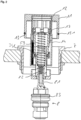
- FIG. 1 Such an installation situation is in Figure 1 shown schematically.
- the handle 11 of the handle 1 projects significantly beyond the collar 71 of the installation sleeve 7, which in this embodiment has an external thread 72 that is screwed with a lock nut 73.
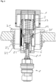
- the handle 1 can now be moved with its adjusting sleeve 14, which is connected to the adapter piece 2 in a longitudinally displaceable manner, by pulling on the handle piece 11 on the adapter piece 2 until the locking lugs 23 of the locking tongues 22 engage in the second, lower locking groove 17 of the adjusting sleeve 14. In this position, the internal toothing 18 of the adjusting sleeve 14 is not engaged with the external toothing 63 of the driver piece 6 (cf. Figure 2 ).
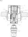
- the adapter piece 2 which is connected to the adjusting sleeve 14 in a rotationally fixed manner, can now be adjusted axially relative to the control cylinder 3 via the thread engagement with the external thread 33 of the control cylinder 3 (cf. Figure 3 ).
- the adjusting sleeve 14 can then be moved along the adapter piece 2 again by pressing on the handle 11 until the locking lugs 23 of the locking tongues 22 engage in the first, upper locking groove 16 of the adjusting sleeve 14.
- the operating unit is now adjusted relative to the installation sleeve 7. It is in the operating position (see. Figure 4 ).
- the control cylinder 3 By pressing the handle 1, the control cylinder 3 is moved via the adjusting sleeve 14 along the control piston 5, with the balls 38 running in the control guide 52.
- the balls 38 can move radially in the elongated holes 35.
- the control piston 5 stops in the control cylinder 3 the balls 38 reach the switching section 521 of the respective control curve 52.
- the control cylinder 3 is moved back by the restoring force of the compression spring 59, whereby the balls 38 are moved into the holding area 522 of the control guide 52.
- the handle 1 In this position, the handle 1 is held by the balls 38. In this position, the handle 1 is completely sunk into the installation sleeve 7 in the retracted position, with the surfaces of the handle 1 and the collar 71 of the installation sleeve 7 lying on the same level.
Landscapes
- Engineering & Computer Science (AREA)
- General Engineering & Computer Science (AREA)
- Mechanical Engineering (AREA)
- Physics & Mathematics (AREA)
- Fluid Mechanics (AREA)
- Mechanically-Actuated Valves (AREA)
- Domestic Plumbing Installations (AREA)
Abstract
Description
- Die Erfindung betrifft eine Bedieneinrichtung für ein Ventiloberteil für Sanitärarmaturen, das eine Steuerspindel aufweist, über die ein Ventilkörper betätigbar ist und die einen Anschlussabschnitt aufweist, wobei die Bedieneinrichtung einen Griff umfasst, der eine Aufnahme zur drehfesten, insbesondere formschlüssigen Verbindung mit dem Anschlussabschnitt der Steuerspindel aufweist.
- Mit Hilfe von Ventiloberteilen wird der Austritt von Medien aus Armaturen gesteuert. Zu diesem Zweck wird das Ventiloberteil mittels seines Kopfstücks in das Gehäuse einer Armatur geschraubt. Ventiloberteile der vorgenannten Art sind in den unterschiedlichsten Ausgestaltungen bekannt. So ist beispielsweise aus der
EP 1 696 162 A1 ein Ventiloberteil bekannt, das ein Kopfstück aufweist, das von einer Spindel durchsetzt ist, die in dem Kopfstück formschlüssig mit einer Steuerscheibe verbunden ist, die an einer ortsfest angeordneten Einlassscheibe anliegt. Durch Drehung der Steuerscheibe gegenüber der Einlassscheibe ist eine Steuerung des Wasserdurchflusses erzielt. Zur Betätigung der Spindel ist diese an ihrer aus dem Kopfstück herausragenden Stirnseite außen als Außenvielkant ausgeführt und innen mit einem Gewindesackloch für die formschlüssige Befestigung eines Drehgriffs versehen. - Aus der
EP 2 522 887 A1 ist weiterhin ein Ventiloberteil bekannt, bei dem zur Steuerung des Durchflusses eines Fluids ein Ventilkörper vorgesehen ist, der über eine Spindel innerhalb des Kopfstücks linear bewegbar ist. Hierbei ist eine Spindel drehbar in einem Kopfstück gelagert und über ein Gewinde mit einem verdrehsicher axial in dem Kopfstück geführten Ventilkörper verbunden. Eine Drehung der Spindel bewirkt so eine axiale Bewegung des Ventilkörpers innerhalb des Kopfstücks. - Bei der Gestaltung von Armaturen wird zunehmend eine Bedienung des Ventiloberteils über Drücker oder Taster gewünscht. Hierzu kommen regelmäßig elektromagnetisch betriebene Ventile zum Einsatz. Nachteilig an diesen Ventiloberteilen ist jedoch, dass die elektromagnetischen Kontakte bei der Verschraubung bzw. Verklebung des Ventiloberteils in Mitleidenschaft gezogen werden können, wodurch die Zuverlässigkeit beeinträchtigt ist. Darüber hinaus erfordern solche Ventile eine zusätzliche Spannungsquelle. Zudem ist bei diesen Ventilen in der Regel keine Mengensteuerung möglich.
- Zur Überwindung dieser Nachteile wird in der
EP 3 366 959 A1 ein Ventiloberteil vorgeschlagen, bei dem der Griff eine Steuerkappe aufweist ist, mit der er entlang des Kopfstücks verschiebbar ist und über die ein Steuerkolben betätigbar ist, wobei in die Mantelfläche des Kopfstücks außen eine zwei Arretierungspositionen aufweisende Kurvenbahn eingebracht ist, in die ein an der Steuerkappe angeordneter Führungsstift eingreift. Durch eine Druckbetätigung des Griffs mit der Steuerkappe ist eine geführte axiale Bewegung des Steuerkolbens erzielt, welche in wenigstens zwei Positionen, beispielsweise in den Positionen "Ventil geöffnet" und "Ventil geschlossen" arretierbar ist. - Die Arretierung über die in der Steuerkappe angeordneten Führungsstifte, die in die Kurvenbahnen eingreifen hat sich in der Praxis bewährt. Gleichwohl erfordert die vorgeschlagene Lösung ein Kopfstück mit einer integrierten Kurvenbahn, wodurch dieses aufwendig herzustellen ist. Darüber hinaus ist eine Nachrüstung von Ventiloberteilen mit einer solchen Druckbetätigung nicht möglich.
- Hier setzt die vorliegende Erfindung an. Der Erfindung liegt die Aufgabe zu Grunde, eine Bedieneinrichtung für ein Ventiloberteil für Sanitärarmaturen bereitzustellen, die aufwandminimiert herstellbar ist und bei der eine Nachrüstung vorhandener Ventiloberteile ermöglicht ist. Gemäß der Erfindung wird diese Aufgabe durch eine Bedieneinrichtung mit den Merkmalen des Patentanspruchs 1 gelöst.
- Mit der Erfindung ist eine Bedieneinrichtung für ein Ventiloberteil für Sanitärarmaturen bereitgestellt, die aufwandminimiert herstellbar ist und bei der eine Nachrüstung vorhandener Ventiloberteile ermöglicht ist. Dadurch, dass der Griff relativ zu der Aufnahme in axialer Richtung verschiebbar angeordnet ist, wobei eine Arretiereinrichtung angeordnet ist, über die der Griff in wenigstens zwei definierten axialen Positionen relativ zu einer von der Aufnahme aufgenommenen Steuerspindel festlegbar ist, ist eine einfache Nachrüstung eines Ventiloberteils mit einer Drückfunktion durch Verbindung dessen Spindel mit der Aufnahme ermöglicht. Die einzige Voraussetzung ist, dass das Ventiloberteil eine Spindel aufweist, durch dessen Drehung eine Betätigung eines Ventilkörpers erfolgt.
- In Weiterbildung der Erfindung umfasst die Arretiereinrichtung einen Steuerkolben, der in einem Steuerzylinder geführt ist und der eine Steuerkulisse aufweist, in die ein an dem Steuerzylinder angeordnetes Eingriffsteil eingreift. Vorzugsweise ist das Eingriffsteil durch eine Kugel gebildet, die in dem Steuerzylinder radial bewegbar geführt ist. Vorzugsweise ist die Kugel zusätzlich auch umlaufend geführt. Hierdurch ist eine durch die Kugeln indizierte Drehung des Griffs bei dessen Betätigung vermieden. Die Kugeln haben gegenüber den im Stand der Technik bekannten Führungsstiften zudem den Vorteil, dass gelegentlich auftretende Fehlfunktionen aufgrund von durch Überbelastung verformten Führungsstiften oder deren Führungen vermieden sind.
- In Ausgestaltung der Erfindung weist der Griff eine Stellhülse auf, die zumindest bereichsweise den Steuerkolben umgibt. Hierdurch ist der Griff entlang des Steuerkolbens geführt, wobei die Arretiereinrichtung zwischen dem Steuerkolben und dem in der Stellhülse angeordneten Steuerzylinder wirkt. Zur radial sowie umlaufend bewegbaren Anordnung einer Kugel, die in die Steuerkulisse des Steuerkolbens eingreift, kann diese in einem an dem Steuerzylinder angeordneten Käfig angeordnet sein. Bevorzugt weist der Steuerkolben einen unrunden Außenquerschnitt auf und der Steuerzylinder weist einen mit diesem Außenquerschnitt korrespondierenden Innenquerschnitt auf, wodurch der Steuerkolben drehfest, jedoch verschiebbar in dem Steuerzylinder geführt ist.
- In weiterer Ausgestaltung der Erfindung ist zwischen dem Steuerzylinder und dem Steuerkolben eine Feder angeordnet, die gegen den Steuerzylinder vorgespannt ist. Hierdurch ist eine automatische Rückführung des mit dem Griff verbundenen Steuerzylinders entlang des Steuerkolbens nach Einwirkung einer Betätigungskraft bewirkt.
- In Weiterbildung der Erfindung weist die Stellhülse eine Innenverzahnung auf, die in eine an dem Steuerkolben angeordnete Außenverzahnung eingreift, wodurch der Griff axial entlang dem Steuerkolben verschiebbar geführt ist. Hierdurch ist eine drehfeste Verbindung der Stellhülse mit dem Steuerkolben bei gleichzeitiger axialer Verschiebbarkeit erzielt. Vorzugsweise ist ein Mitnehmerstück angeordnet, dass die Außenverzahnung aufweist und das mit dem Steuerkolben drehfest verbunden ist.
- Bevorzugt ist die Aufnahme zur Verbindung mit dem Anschlussabschnitt einer Steuerspindel an dem Steuerkolben angeordnet. Vorteilhaft ist die Aufnahme zur formschlüssigen Verbindung mit einem entsprechend unrund ausgebildeten Anschlussabschnitt einer Steuerspindel ausgebildet. Dadurch ist eine Übertragung eines Drehmoments von dem Griff auf den Steuerkolben und einer mit diesem verbundenen Steuerspindel eines Ventiloberteils ermöglicht. Durch Drücken auf den Griff kann dieser über die Arretiereinrichtung aus einer eingefahrenen Position in eine Bedienposition herausbewegt werden, wonach durch Drehen an dem Griff eine Betätigung eines mit diesem verbundenen Ventiloberteils erfolgen kann.
- In Ausgestaltung der Erfindung weist der Steuerzylinder ein Außengewinde auf, auf das ein Adapterstück mit seinem Innengewinde aufgeschraubt ist, wobei das Adapterstück in der Stellhülse des Griffs drehfest sowie längsverschieblich gehalten ist. Hierdurch ist eine Feineinstellung der axialen Position des Griffs an der Steuerspindel eines in einer Wand eingebauten Ventiloberteils ermöglicht. Durch eine Längsverschiebung des Griffs in eine Justierposition, in welcher die Stellhülse nicht mit ihrer Innenverzahnung in die Außenverzahnung des Steuerkolbens eingreift, erfolgt durch eine Drehung des Griffs eine Längsverstellung des Adapterstücks entlang des Außengewindes des Steuerzylinders. Ungenauigkeiten im Zuge des Einbaus eines Ventiloberteils und der in diesem Zuge üblicherweise erfolgten bedarfsgerechten Ablängung der Steuerspindel können so durch Verstellung des Adapterstücks ausgeglichen werden.
- In weiterer Ausgestaltung weist das Adapterstück Rastnasen auf, wobei innen in der Stellhülse wenigstens eine Rastnut angeordnet ist, mit der die Rastnasen in einer definierten Position des Adapterstücks verrastbar sind. Hierdurch ist eine definierte axiale Positionierung des Adapterstücks in der Stellhülse ermöglicht, in der kein Eingriff ihrer Innenverzahnung in die Außenverzahnung des Steuerkolbens besteht (Justierposition).
- Bevorzugt sind innen in der Stellhülse axial beabstandet zueinander wenigstens zwei Rastnuten vorzugsweise radial umlaufend angeordnet. Hierdurch ist eine erste axiale Positionierung des Adapterstücks für die Justierung und eine zweite definierte Positionierung des Adapterstücks in Betriebsposition mit Eingriff ihrer Innenverzahnung in die Außenverzahnung des Steuerkolbens ermöglicht.
- In weiterer Ausgestaltung der Erfindung ist eine Einbauhülse angeordnet, deren Innendurchmesser im Wesentlichen dem Außendurchmesser des Griffs entspricht wobei die Position des Griffs in einem definierten Abstand zur Einbauhülse einstellbar ist. Vorzugsweise weist die Einbauhülse einen umlaufenden Kragen auf, der bei Positionierung des Griffs in einer definierten Position in der Einbauhülse mit der Oberfläche des Griffs eine gemeinsame Ebene ausbildet. Hierdurch ist eine optisch ansprechende Integration des Griffs in eine diese umgebene Ebene ermöglicht. Der Kragen kann sowohl ringförmig als auch in Form einer Platte jedweder geometrischen Form ausgebildet sein.
- Gegenstand der vorliegenden Erfindung ist weiterhin ein Ventiloberteil für Sanitärarmaturen mit einer solchen Bedieneinrichtung nach dem Patentanspruch 13 sowie eine Sanitärarmatur mit einem Ventiloberteil für Sanitärarmaturen mit einer solchen Bedieneinrichtung nach dem Patentanspruch 14.
- Unter der Justierposition ist vorliegend die Stellung des Griffs zu verstehen, in der die Rastnasen des Adapterstücks in die zweite, untere Rastnut der Stellhülse eingreift. In dieser Position ist eine Justierung über den Gewindeeingriff zwischen dem Außengewinde des Steuerzylinders und dem Innengewinde des Adapterstücks ermöglicht. Die Innenverzahnung der Stellhülse ist außer Eingriff mit der Außenverzahnung des Steuerkolbens.
- Unter der Betriebsposition ist vorliegend die Stellung des Griffs zu verstehen, in der die Rastnasen des Adapterstücks in die erste, obere Rastnut der Stellhülse eingreift. In dieser Position ist die Innenverzahnung der Stellhülse im Eingriff mit der Außenverzahnung des Steuerkolbens. Eine Justierung über den Gewindeeingriff zwischen dem Außengewinde des Steuerzylinders und dem Innengewinde des Adapterstücks ist nicht möglich.
- Unter der Bedienposition ist vorliegend die Stellung des Griffs zu verstehen, in der die Kugeln in der oberen Position der Steuerkulisse anliegen. Der Griff ist so zur einfachen Bedienung "ausgefahren".
- Unter der eingefahrenen Position ist vorliegend die Stellung des Griffs zu verstehen, in der die Kugeln im Haltebereich der Steuerkulisse anliegen. Der Griff ist hier in einer eingefahrenen Position arretiert, in der beispielsweise der Griff bündig mit einer diesen Griff einfassenden Umgebung ist.
- Andere Weiterbildungen und Ausgestaltungen der Erfindung sind in den übrigen Unteransprüchen angegeben. Ausführungsbeispiele sind in den Zeichnungen dargestellt und werden nachfolgend im Einzelnen beschrieben. Es zeigen:
- Figur 1:
- die schematische Darstellung eines Ventiloberteils mit einer Bedieneinrichtung nach einer Grobmontage mit Griff in Bedienposition;
- Figur 2:
- die schematische Darstellung des Ventiloberteils mit Bedieneinrichtung nach
Figur 1 mit Griff in Justierposition (vor erfolgter Justierung); - Figur 3:
- die schematische Darstellung des Ventiloberteils mit Bedieneinrichtung nach
Figur 2 nach erfolgter Justierung des Griffs; - Figur 4:
- die schematische Darstellung des Ventiloberteils mit Bedieneinrichtung nach
Figur 3 mit Griff in Betriebsposition; - Figur 5:
- die Darstellung des Ventiloberteils mit Bedieneinrichtung aus
Figur 4 mit Griff in eingefahrener Position; - Figur 6:
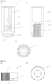
- die schematische Darstellung der Stellhülse des Griffs der Bedieneinrichtung aus Figur 1 a) im Teilschnitt, b) in der Draufsicht;
- Figur 7:
- die schematische Darstellung des Adapterstücks der Bedieneinrichtung aus Figur 1 a) im Teilschnitt, b) in der Draufsicht;
- Figur 8:
- die schematische Darstellung des Steuerzylinders der Bedieneinrichtung aus Figur 1 a) im Teilschnitt, b) in der Draufsicht;
- Figur 9:
- die schematische Darstellung der Begrenzungshülse des Steuerzylinders der Bedieneinrichtung aus Figur 1 a) im Teilschnitt, b) in der Draufsicht;
- Figur 10:
- die schematische Darstellung des Steuerkolbens der Bedieneinrichtung aus Figur 1 a) in der Seitenansicht; b) im Längsschnitt; c) in der Draufsicht;
- Figur 11:
- die schematische Darstellung des Mitnehmerstücks des Steuerkolbens der Bedieneinrichtung aus Figur 1 a) im Teilschnitt, b) in der Draufsicht.
- Figur 12:
- die schematische Darstellung der Bedieneinrichtung (ohne Griff) aus
Figur 3 in Bedienposition - Figur 13:
- die Detaildarstellung des Kugelkäfigs der Bedieneinrichtung aus
Figur 12 ; - Figur 14:
- die Darstellung der Bedieneinrichtung aus
Figur 12 mit erhöhter Zuglast am Steuerzylinder und - Figur 15:
- die Detaildarstellung des Kugelkäfigs der Bedieneinrichtung aus
Figur 14 . - Die als Ausführungsbeispiel gemäß
Figur 1 gewählte Bedieneinrichtung umfasst im Wesentlichen einen Griff 1, in dem ein Adapterstück 2 axial verschiebbar angeordnet ist, das einen Steuerzylinder 3 aufnimmt, mit dem es im Gewindeeingriff ist, der endseitig mit einer Begrenzungshülse 4 versehen ist und in dem ein Steuerkolben 5 axial verschiebbar angeordnet ist, der endseitig mit einem Mitnehmerstück 6 versehen ist und der eine Aufnahme zur formschlüssigen Verbindung mit dem in diesem Beispiel unrunden Anschlussabschnitt 82 der Steuerspindel 81 eines Ventiloberteils 8 aufweist. Alternativ kann der Anschlussabschnitt der Steuerspindel 81 auch zylindrisch ausgebildet sein. In diesem Fall ist eine drehfeste Verbindung beispielsweise mittels Kleben erforderlich. - Der Griff 1 ist aus einem hohlzylindrischen, topfförmig ausgebildeten Griffstück 11 gebildet, das innen zentrisch eine Gewindebohrung 12 aufweist, in die koaxial zur zylindrischen Seitenwand des Griffstücks 11 eine Stellhülse 14 eingeschraubt und verklebt ist. Alternativ kann der Griff 1 auch einteilig ausgeführt sein. Außen ist das Griffstück 11 mit einer Dichtungsnut 13 versehen, die einen O-Ring 131 aufnimmt. Griffstück 11 und Stellhülse 12 sind im Ausführungsbeispiel als Messingdrehteile hergestellt.
- Die Stellhülse 14 ist im Wesentlichen hohlzylindrisch ausgebildet und weist einen ersten Abschnitt 141 auf, an den sich ein zweiter, durchmessererweitertet Abschnitt 143 anschließt. Der erste Abschnitt 141 ist außen mit einem Außengewinde 15 versehen, mit dem die Stellhülse in 14 in die Gewindebohrung 12 des Griffstücks 11 eingeschraubt und verklebt ist. In seine einen weitgehend zwölfeckförmigen Querschnitt aufweisende Innenmantelfläche sind in dem ersten Abschnitt 141 eine erste, obere Rastnut 16 und beabstandet zu dieser eine zweite, untere Rastnut 17 angeordnet. Die weitgehend zwölfeckförmige Querschnittskontur der Innenmantelfläche des ersten Abschnitts 141 dient der drehfesten Aufnahme des Adapterstücks 2, dessen Außenmantelfläche eine hierzu korrespondierende zwölfeckförmige Querschnittskontur aufweist. Die weitgehend zwölfeckförmige Querschnittskontur der Innenmantelfläche des ersten Abschnitts 141 sowie der Außenmantelfläche des Adapterstücks 2 ist durch sechs regelmäßig beabstandet in die Zylindermantelfläche eingebrachte rechteckige Abflachungen 142, 21 erzielt.
- Alternativ kann an Stelle der zwölfeckförmigen Querschnittskontur auch jedwede andere unrunde, vorzugsweise vieleckige Kontur verwendet werden. Der zweite Abschnitt 143 ist mit einer Innenverzahnung 18 versehen, die sich weitgehend über die gesamte Innenmantelfläche des zweiten Abschnitts 143 erstreckt. Die Innenmantelfläche des zweiten Abschnitts 143 weist eine weitgehend achteckförmige Querschnittskontur auf, die durch vier regelmäßig beabstandet in die mit der Innenverzahnung 18 versehene Zylinderinnenmantelfläche eingebrachte rechteckige Abflachungen 144 erzielt ist.
- Das Adapterstück 2 ist im Wesentlichen hohlzylindrisch ausgebildet und weist, wie bereits ausgeführt, eine mit der Innenmantelfläche der Stellhülse 14 korrespondierende Außenmantelfläche mit nahezu zwölfeckförmigem Querschnitt auf. Im Bereich einer jeden Abflachung 21 ist in das Adapterstück 2 an seinem der Gewindebohrung 12 des Griffstücks 11 zugewandten Seite jeweils eine rechteckige Ausnehmung eingebracht, wodurch umlaufend sechs regelmäßig beabstandet zueinander angeordnete Rastzungen 22 begrenzt sind, die radial verlaufende, nach außen kragende Rastnasen 23 zum Eingriff in die Rastnuten 16, 17 der Stellhülse 14 aufweisen. Auf seiner Innenmantelfläche ist das Adapterstück 2 mit einem Innengewinde 24 versehen. Im Ausführungsbeispiel ist das Adapterstück 2 aus Kunststoff hergestellt.
- Der Steuerzylinder 3 ist als im Wesentlichen hohlzylindrisches Messingdrehteil ausgebildet. An seiner dem Adapterstück 2 zugewandten Stirnseite weist der Steuerzylinder 3 einen innendurchmesserverjüngenden Absatz 31 auf, in den innen eine Stufe 32 eingebracht ist. Außen weist der Steuerzylinder 3 ein Außengewinde 33 auf, das sich etwa über die Hälfe seiner Länge erstreckt. Beabstandet zu dem Außengewinde 33 ist eine Nut 34 zur Aufnahme eines O-rings 341 angeordnet. An die Nut 34 schließen sich zwei diametral gegenüberliegende, radial sich erstreckende Langlochbohrungen 35 an, die von zwei axial beabstandet angeordneten, umlaufenden Stegen 36 eingefasst sind. Zwischen den Langlochbohrungen 35 und dem Außengewinde 33 weist der Steuerzylinder 3 innen einen durchmesserverjüngenden Absatz 37 auf, in den umlaufend radial beabstandet vier Führungskerben 371 eingebracht sind. Die Führungskerben 371 dienen der drehfesten Führung des Steuerkolbens 4.
- In die beiden Langlochbohrungen 35 ist jeweils eine Kugel 38 eingebracht, deren Durchmesser etwas kleiner ist, als die Breite der Langlochbohrung 35, so dass diese bereichsweise durch die jeweilige Langlochbohrung 35 hindurchragt und zwischen den Stegen 36 radial und umlaufend beweglich geführt ist. An seinem die Langlochbohrungen 35 aufweisenden endseitigen Abschnitt ist auf dem Steuerzylinder 3 eine Begrenzungshülse 4 vorhanden, in der eine Ringfeder 9 angeordnet ist. Die Begrenzungshülse 4 umgreift die Stege 36 und ist durch einen O-Ring 341 gehalten. Die Begrenzungshülse 4 bildet mit den Stegen 36, der Ringfeder 9 und den Langlochbohrungen 35 einen Kugelkäfig für die beiden Kugeln 38 aus, durch den ihre Bewegung in radialer Richtung begrenzt ist.
- Der Steuerkolben 5 ist als im Wesentlichen zylindrisches Messingdrehteil ausgebildet. In seine zylindrische Außenmantelfläche sind radial beabstandet zueinander vier Abflachungen 51 eingebracht, wodurch ein im Wesentlichen achteckförmiger Querschnitt gebildet ist. Über die so gebildeten Ecken ist der Steuerkolben 5 in den Führungskerben 371 des Steuerzylinders 3 geführt. Jeweils zwischen zwei Abflachungen 51 sind in die Außenmantelfläche weiterhin diametral gegenüberliegend zwei Steuerkulissen 52 eingebracht. An seinem dem Steuerzylinder 3 abgewandten Ende ist ein durchmesserreduzierter Absatz 53 angeordnet, der ein Außengewinde 531 aufweist. Durch den Absatz 53 hindurch erstreckt sich eine in Form eines Innenvielecks ausgebildete Aufnahme 54 für die ein Außenvieleck aufweisende Steuerspindel 81 eines Ventiloberteils 8. An die Aufnahme 54 schließt sich ein innendurchmesserverjüngter Abschnitt 55 an, in den zentrisch eine Kegelbohrung 56 zur Aufnahme des Kopfes einer Senkkopfschraube 82 eingebracht ist. An den innendurchmesserverjüngten Abschnitt 55 schließt sich ein innendurchmessererweiterter Abschnitt 58 an, durch den ein Absatz 57 gebildet ist, der als Federsitz für eine Druckfeder 59 dient.
- Das Mitnehmerstück 6 ist als im Wesentlichen hohlzylindrisches Messingdrehteil ausgebildet und weist an seinem dem Steuerzylinder 3 entgegengesetzten Ende einen innendurchmesserverjüngten Abschnitt 61 auf, der mit einem Innengewinde 62 versehen ist. Die Außenmantelfläche des Mitnehmerstücks 6 ist mit einer Außenverzahnung 63 zum Eingriff in die Innenverzahnung 18 der Stellhülse 14 versehen.
- Das Adapterstück 2 ist mit seinem Innengewinde 24 auf das Außengewinde 33 des Steuerzylinders 3 geschraubt. In den Steuerzylinder 3 ist der Steuerkolben 5 eingesetzt, der durch seine mit der Innenmantelfläche des Steuerzylinders 3 korrespondierend ausgebildete unrunde Außenmantelfläche in dem Steuerzylinder 3 drehfest, jedoch axial verschiebbar geführt ist. Die durch die Langlochbohrungen 35 des Steuerzylinders 3 bereichsweise hindurchtretenden Kugeln 38 greifen dabei jeweils in eine Steuerkulisse 52 des Steuerkolbens 5 ein. An dem Absatz 57 des Steuerkolbens 5 liegt die Druckfeder 59 an, die auf ihrer gegenüberliegenden Seite gegen die Stellhülse vorgespannt ist.
- In Betriebsposition des Griffs 1 mit seiner Stellhülse 14, in der die Rastnasen 23 der Rastzungen 22 des auf diesem aufgeschraubten Adapterstücks 2 in die obere, erste Rastnut 16 der Stellhülse 14 eingreifen, ist die Innenverzahnung der Stellhülse 14 mit der Außenverzahnung 63 des Mitnehmerstücks 6 im Eingriff. In dieser Betriebsposition ist eine Übertragung eines Drehmoments von dem Griff 1 auf das mit der Steuerspindel 81 des Ventiloberteils 8 verbundenen Mitnehmerstücks 6 ermöglicht. Das Ventiloberteil 8 ist im Ausführungsbeispiel gemäß der
EP 1 696 162 A1 ausgebildet. Es weist eine Kopfstück 83 auf, das von der Steuerspindel 81 axial durchsetzt ist. - Bei der wandseitigen Montage einer Sanitärarmatur, beispielsweise einer Duscharmatur, werden die Wasserleitungen von dem Installateur in der Wand an ein Ventiloberteil 8 der Armatur angeschlossen. Das Ventiloberteil 8 weist regelmäßig eine lange Steuerspindel 81 auf, die nach Fertigstellung der wandseitigen Arbeiten, einschließlich möglicher Fliesenarbeiten, auf ein gewünschtes Maß abgelängt wird. Die Steuerspindel 81 einrahmend ist der Wanddurchtritt mit einer Einbauhülse 7 versehen. Die Steuerspindel 81 wird mit ihrer Außenverzahnung in die eine Innenverzahnung aufweisende Aufnahme 54 des Steuerkolbens 5 eingeführt und über eine Senkkopfschraube 82 befestigt. Eine solche Einbausituation ist in
Figur 1 schematisch dargestellt. Aufgrund von Ungenauigkeiten beim Einbau des Ventiloberteils 8 und dem Ablängen der Steuerspindel 81 ragt das Griffstück 11 des Griffs 1 deutlich über den Kragen 71 der Einbauhülse 7 hinaus, die in diesem Ausführungsbeispiel ein Außengewinde 72 aufweist, das mit einer Kontermutter 73 verschraubt ist. - Der Griff 1 kann nun mit seiner längsverschieblich mit dem Adapterstück 2 verbundenen Stellhülse 14 durch Ziehen an dem Griffstück 11 auf dem Adapterstück 2 verschoben werden, bis die Rastnasen 23 der Rastzungen 22 in die zweite, untere Rastnut 17 der Stellhülse 14 einrasten. In dieser Position ist die Innenverzahnung 18 der Stellhülse 14 außer Eingriff mit der Außenverzahnung 63 des Mitnehmerstücks 6 (vgl.
Figur 2 ). Durch Drehen an dem Griffstück 11 kann nun das drehfest mit der Stellhülse 14 verbundene Adapterstück 2 über den Gewindeeingriff mit dem Außengewinde 33 des Steuerzylinders 3 axial relativ zu diesem verstellt werden (vgl.Figur 3 ). - Bei der Umstellung des Griffs 1 mit seiner Stellhülse 14 aus der Betriebsposition in die Justierposition ist zum Ausbringen der Rastnasen 23 der Rastzungen 22 aus der ersten, oberen Rastnut 16 eine Zugkraft erforderlich, um die Rastnasen 23 in die zweite, untere Rastnut 17 zu verbringen. Durch diese Zugkraft wird zugleich eine Zugkraft zwischen Steuerzylinder 3 und Steuerkolben erzeugt, wodurch die an in der Steuerkulisse 52 des Steuerkolbens 5 geführten Kugeln 38 radial nach außen gegen die Ringfeder 9 gedrückt werden. Durch die Begrenzungshülse 4 ist ein Austreten der Kugeln 38 aus der Steuerkulisse 52 verhindert (vgl.
Figuren 13 und 15 ). - Nachfolgend kann die Stellhülse 14 durch Druck auf das Griffstück 11 wieder entlang des Adapterstücks 2 verschoben werden, bis die Rastnasen 23 der Rastzungen 22 in die erste, obere Rastnut 16 der Stellhülse 14 einrasten. Die Bedieneinheit ist nun gegenüber der Einbauhülse 7 justiert. Sie befindet sich in der Betriebsposition (vgl.
Figur 4 ). - Durch Drücken des Griffs 1 wird der Steuerzylinder 3 über die Stellhülse 14 entlang des Steuerkolbens 5 bewegt, wobei die Kugeln 38 in der Steuerkulisse 52 laufen. Hierbei können sich die Kugeln 38 in den Langlochbohrungen 35 radial bewegen. Am Anschlag des Steuerkolbens 5 in dem Steuerzylinder 3 erreichen die Kugeln 38 den Umschaltabschnitt 521 der jeweiligen Steuerkurve 52. Nach Loslassen des Griffs 1 wird der Steuerzylinder 3 durch die Rückstellkraft der Druckfeder 59 zurückbewegt, wodurch die Kugeln 38 in den Haltebereich 522 der Steuerkulisse 52 bewegt werden. In dieser Stellung ist der Griff 1 durch die Kugeln 38 gehalten. In dieser Position ist der Griff 1 vollständig in die Einbauhülse 7 versenkt in der eingefahrenen Position, wobei die Oberflächen von Griff 1 und Kragen 71 der Einbauhülse 7 auf einer Ebene liegen.
- Bei erneutem Drücken des Griffs 1 werden die Kugeln 38 aus dem Haltebereich 522 der Steuerkulisse 52 herausbewegt. Nach Loslassen des Griffs 1 wird der Steuerzylinder 3 durch die Rückstellkraft der Druckfeder 59 nun vollständig zurückbewegt. In dieser Bedienposition ragt der Griff weit aus der Einbauhülse 7 hinaus. Durch den Eingriff der Innenverzahnung 18 der Stellhülse 14 mit der Außenverzahnung 63 des Mitnehmerstücks 6, das über den Steuerkolben 5 mit der Steuerspindel 81 des Ventiloberteils 8 verbunden ist, kann nun eine Betätigung des Ventiloberteils 8 durch eine Drehung der Steuerspindel 81 über den Griff 1 erfolgen. Nach erfolgter Betätigung des Ventiloberteils 8 kann durch erneutes Drücken des Griffs 1 dieser wieder in der Einbauhülse 7 versenkt werden.
Claims (14)
- Bedieneinrichtung für ein Ventiloberteil für Sanitärarmaturen, das eine Steuerspindel aufweist, über die ein Ventilkörper betätigbar ist und die einen Anschlussabschnitt aufweist, wobei die Bedieneinrichtung einen Griff (1) umfasst, der eine Aufnahme (54) zur drehfesten Verbindung mit dem Anschlussabschnitt der Steuerspindel (81) aufweist, dadurch gekennzeichnet, dass der Griff (1) relativ zu der Aufnahme (54) in axialer Richtung verschiebbar angeordnet ist, wobei eine Arretiereinrichtung angeordnet ist, über die der Griff (1) in wenigstens zwei definierten axialen Positionen relativ zu einer von der Aufnahme (54) aufgenommenen Steuerspindel (81) festlegbar ist.
- Bedieneinrichtung nach Anspruch 1, dadurch gekennzeichnet, dass die Arretiereinrichtung einen Steuerkolben (5) umfasst, der in einem Steuerzylinder (3) geführt ist und der eine Steuerkulisse (52) aufweist, in die ein an dem Steuerzylinder (3) angeordnetes Eingriffsteil eingreift.
- Bedieneinrichtung nach Anspruch 2, dadurch gekennzeichnet, dass das Eingriffsteil durch eine Kugel (38) gebildet ist, die in dem Steuerzylinder (3) radial sowie vorzugsweise auch umlaufend bewegbar geführt ist.
- Bedieneinrichtung nach Anspruch 2 oder 3, dadurch gekennzeichnet, dass der Griff (1) eine Stellhülse (14) aufweist, die zumindest bereichsweise den Steuerkolben (5) umgibt.
- Bedieneinrichtung nach Anspruch 4, dadurch gekennzeichnet, dass zwischen dem Steuerzylinder (3) und dem Steuerkolben (5) eine Feder (59) angeordnet ist, die gegen den Steuerzylinder (3) vorgespannt ist.
- Bedieneinrichtung nach Anspruch 4 oder 5, dadurch gekennzeichnet, dass die Stellhülse (14) eine Innenverzahnung (18) aufweist, die in eine an dem Steuerkolben (5) angeordnete Außenverzahnung (63) eingreift, wodurch der Griff (1) axial entlang dem Steuerkolben (5) verschiebbar geführt ist.
- Bedieneinrichtung nach einem der vorgenannten Ansprüche, dadurch gekennzeichnet, dass die Aufnahme (54) zur Verbindung mit dem Anschlussabschnitt der Steuerspindel (81) an dem Steuerkolben (5) angeordnet ist.
- Bedieneinrichtung nach einem der Ansprüche 4 bis 7, dadurch gekennzeichnet, dass der Steuerzylinder (3) ein Außengewinde (33) aufweist, auf das ein Adapterstück (2) mit seinem Innengewinde (24) aufgeschraubt ist, wobei das Adapterstück (2) in der Stellhülse (14) des Griffs (1) drehfest sowie längsverschieblich gehalten ist.
- Bedieneinrichtung nach Anspruch 8, dadurch gekennzeichnet, dass das Adapterstück (2) Rastnasen (23) aufweist, wobei innen in der Stellhülse (14) wenigstens eine Rastnut (16, 17) angeordnet ist, mit der die Rastnasen (23) in einer definierten Position des Adapterstücks (2) in der Stellhülse (14) verrastbar sind.
- Bedieneinrichtung nach Anspruch 9, dadurch gekennzeichnet, dass innen in der Stellhülse (14) axial beabstandet zueinander wenigstens zwei Rastnuten (16, 17) vorzugsweise radial umlaufend angeordnet sind.
- Bedieneinrichtung nach einem der vorgenannten Ansprüche, dadurch gekennzeichnet, dass eine Einbauhülse (7) angeordnet ist, deren Innendurchmesser im Wesentlichen dem Außendurchmesser des Griffs (1) entspricht, wobei die Position des Griffs (1) in einem definierten Abstand zur Einbauhülse (7) einstellbar ist.
- Bedieneinrichtung nach Anspruch 11, dadurch gekennzeichnet, dass die Einbauhülse (7) einen umlaufenden Kragen (71) aufweist, der bei Positionierung des Griffs (1) in einer definierten Position in der Einbauhülse (7) mit der Oberfläche des Griffs (1) eine gemeinsame Ebene ausbildet.
- Ventiloberteil für Sanitärarmaturen, das eine Steuerspindel (81) aufweist, über die ein Ventilkörper betätigbar ist und die einen unrunden Anschlussabschnitt aufweist, dadurch gekennzeichnet, dass die Steuerspindel (81) mit der Aufnahme (54) einer Bedieneinrichtung nach einem der vorgenannten Ansprüche verbunden ist.
- Sanitärarmatur mit einem Ventiloberteil, das eine Steuerspindel (81) aufweist, über die ein Ventilkörper betätigbar ist und die einen unrunden Anschlussabschnitt aufweist, dadurch gekennzeichnet, dass die Steuerspindel (81) mit der Aufnahme einer Bedieneinrichtung nach einem der Ansprüche 1 bis 12 verbunden ist.
Priority Applications (6)
| Application Number | Priority Date | Filing Date | Title |
|---|---|---|---|
| ES23161220T ES3035643T3 (en) | 2023-03-10 | 2023-03-10 | Operating device for a valve top for sanitary fittings |
| EP23161220.1A EP4428405B1 (de) | 2023-03-10 | 2023-03-10 | Bedieneinrichtung für ein ventiloberteil für sanitärarmaturen |
| DE112024000368.0T DE112024000368A5 (de) | 2023-03-10 | 2024-02-08 | Bedieneinrichtung für ein Ventiloberteil für Sanitärarmaturen |
| PCT/EP2024/053246 WO2024188558A1 (de) | 2023-03-10 | 2024-02-08 | Bedieneinrichtung für ein ventiloberteil für sanitärarmaturen |
| CN202480017431.0A CN120858246A (zh) | 2023-03-10 | 2024-02-08 | 用于针对卫生配件的阀上部件的操作装置 |
| TW113105991A TW202445049A (zh) | 2023-03-10 | 2024-02-20 | 針對用於衛浴水龍頭的閥門上部的操作裝置 |
Applications Claiming Priority (1)
| Application Number | Priority Date | Filing Date | Title |
|---|---|---|---|
| EP23161220.1A EP4428405B1 (de) | 2023-03-10 | 2023-03-10 | Bedieneinrichtung für ein ventiloberteil für sanitärarmaturen |
Publications (3)
| Publication Number | Publication Date |
|---|---|
| EP4428405A1 true EP4428405A1 (de) | 2024-09-11 |
| EP4428405B1 EP4428405B1 (de) | 2025-04-16 |
| EP4428405C0 EP4428405C0 (de) | 2025-04-16 |
Family
ID=85571190
Family Applications (1)
| Application Number | Title | Priority Date | Filing Date |
|---|---|---|---|
| EP23161220.1A Active EP4428405B1 (de) | 2023-03-10 | 2023-03-10 | Bedieneinrichtung für ein ventiloberteil für sanitärarmaturen |
Country Status (6)
| Country | Link |
|---|---|
| EP (1) | EP4428405B1 (de) |
| CN (1) | CN120858246A (de) |
| DE (1) | DE112024000368A5 (de) |
| ES (1) | ES3035643T3 (de) |
| TW (1) | TW202445049A (de) |
| WO (1) | WO2024188558A1 (de) |
Citations (11)
| Publication number | Priority date | Publication date | Assignee | Title |
|---|---|---|---|---|
| DE2856242A1 (de) * | 1978-12-27 | 1980-07-03 | Integral Hydraulik Co | Einfach entsperrbares rueckschlagventil |
| JP2005264459A (ja) * | 2004-03-16 | 2005-09-29 | Toto Ltd | 開閉弁装置及びそれを備えた水栓装置 |
| EP1696162A1 (de) | 2005-02-23 | 2006-08-30 | Flühs Drehtechnik GmbH | Ventiloberteil für Armaturen |
| EP1736695A1 (de) * | 2005-06-24 | 2006-12-27 | Weidmann Plastics Technology AG | Ventil insbesondere für eine Sanitärarmatur |
| EP2522887A1 (de) | 2011-05-09 | 2012-11-14 | Flühs Drehtechnik GmbH | Ventiloberteil |
| DE102012221043A1 (de) * | 2012-11-19 | 2014-05-22 | Hansgrohe Se | Sanitärventil |
| EP3366959A1 (de) | 2017-02-23 | 2018-08-29 | Flühs Drehtechnik GmbH | Ventiloberteil |
| JP2019066007A (ja) * | 2017-10-03 | 2019-04-25 | 株式会社Lixil | 弁装置 |
| US20190178398A1 (en) * | 2017-12-07 | 2019-06-13 | Hansgrohe Se | Valve actuation device and sanitary valve |
| EP3561351A1 (de) * | 2018-04-25 | 2019-10-30 | Hansgrohe SE | Misch- und absperrventilvorrichtung sowie sanitäre misch- und absperrarmatur |
| EP3919797A1 (de) * | 2020-05-26 | 2021-12-08 | Kohler Mira Limited | Steuerung einer armatur für rituelle waschung |
-
2023
- 2023-03-10 EP EP23161220.1A patent/EP4428405B1/de active Active
- 2023-03-10 ES ES23161220T patent/ES3035643T3/es active Active
-
2024
- 2024-02-08 WO PCT/EP2024/053246 patent/WO2024188558A1/de not_active Ceased
- 2024-02-08 DE DE112024000368.0T patent/DE112024000368A5/de active Pending
- 2024-02-08 CN CN202480017431.0A patent/CN120858246A/zh active Pending
- 2024-02-20 TW TW113105991A patent/TW202445049A/zh unknown
Patent Citations (12)
| Publication number | Priority date | Publication date | Assignee | Title |
|---|---|---|---|---|
| DE2856242A1 (de) * | 1978-12-27 | 1980-07-03 | Integral Hydraulik Co | Einfach entsperrbares rueckschlagventil |
| JP2005264459A (ja) * | 2004-03-16 | 2005-09-29 | Toto Ltd | 開閉弁装置及びそれを備えた水栓装置 |
| EP1696162A1 (de) | 2005-02-23 | 2006-08-30 | Flühs Drehtechnik GmbH | Ventiloberteil für Armaturen |
| EP1736695A1 (de) * | 2005-06-24 | 2006-12-27 | Weidmann Plastics Technology AG | Ventil insbesondere für eine Sanitärarmatur |
| EP2522887A1 (de) | 2011-05-09 | 2012-11-14 | Flühs Drehtechnik GmbH | Ventiloberteil |
| DE102012221043A1 (de) * | 2012-11-19 | 2014-05-22 | Hansgrohe Se | Sanitärventil |
| EP3366959A1 (de) | 2017-02-23 | 2018-08-29 | Flühs Drehtechnik GmbH | Ventiloberteil |
| EP3366958A1 (de) * | 2017-02-23 | 2018-08-29 | Flühs Drehtechnik GmbH | Ventiloberteil |
| JP2019066007A (ja) * | 2017-10-03 | 2019-04-25 | 株式会社Lixil | 弁装置 |
| US20190178398A1 (en) * | 2017-12-07 | 2019-06-13 | Hansgrohe Se | Valve actuation device and sanitary valve |
| EP3561351A1 (de) * | 2018-04-25 | 2019-10-30 | Hansgrohe SE | Misch- und absperrventilvorrichtung sowie sanitäre misch- und absperrarmatur |
| EP3919797A1 (de) * | 2020-05-26 | 2021-12-08 | Kohler Mira Limited | Steuerung einer armatur für rituelle waschung |
Also Published As
| Publication number | Publication date |
|---|---|
| CN120858246A (zh) | 2025-10-28 |
| EP4428405B1 (de) | 2025-04-16 |
| ES3035643T3 (en) | 2025-09-05 |
| EP4428405C0 (de) | 2025-04-16 |
| DE112024000368A5 (de) | 2025-10-09 |
| WO2024188558A1 (de) | 2024-09-19 |
| TW202445049A (zh) | 2024-11-16 |
Similar Documents
| Publication | Publication Date | Title |
|---|---|---|
| EP3366959B1 (de) | Ventiloberteil | |
| DE202023101160U1 (de) | Ventiloberteil für Sanitärarmaturen | |
| DE202023101163U1 (de) | Ventiloberteil für Sanitärarmaturen | |
| DE19901654A1 (de) | Eckventil mit Rosettengriff | |
| DE4025488A1 (de) | Rueckschlagventil | |
| EP1870526A1 (de) | Sanitärarmatur | |
| EP4428405B1 (de) | Bedieneinrichtung für ein ventiloberteil für sanitärarmaturen | |
| EP4428414B1 (de) | Ventiloberteil für sanitärarmaturen | |
| EP4428406B1 (de) | Ventiloberteil für sanitärarmaturen | |
| EP4428407B1 (de) | Ventiloberteil für sanitärarmaturen | |
| DE3621559C2 (de) | ||
| EP4585838B1 (de) | Ventiloberteil für sanitärarmaturen | |
| DE202023101162U1 (de) | Bedieneinrichtung für ein Ventiloberteil für Sanitärarmaturen | |
| DE202023101164U1 (de) | Ventiloberteil für Sanitärarmaturen | |
| WO2005093299A1 (de) | Vorrichtung zum antrieb eines doppelsitzventils | |
| EP4224042B1 (de) | Rückflussverhindererventil | |
| EP0093783B1 (de) | Durchströmventil | |
| EP4522552B1 (de) | Hauptventileinsatz für ein zapfventil | |
| DE69412427T2 (de) | Kraftstoffeinspritzdüse | |
| EP3537017A1 (de) | Ventil | |
| EP3693643B1 (de) | Ventiloberteil für sanitärarmaturen | |
| EP4513064A1 (de) | Absperrventil | |
| EP4286723A1 (de) | Absperrventil | |
| DE1629877C (de) | Sicherheitsgasanschlußhahn für Steckeranschluß | |
| EP1384924B1 (de) | Plättchen-Rückschlagventil |
Legal Events
| Date | Code | Title | Description |
|---|---|---|---|
| PUAI | Public reference made under article 153(3) epc to a published international application that has entered the european phase |
Free format text: ORIGINAL CODE: 0009012 |
|
| STAA | Information on the status of an ep patent application or granted ep patent |
Free format text: STATUS: REQUEST FOR EXAMINATION WAS MADE |
|
| 17P | Request for examination filed |
Effective date: 20231208 |
|
| AK | Designated contracting states |
Kind code of ref document: A1 Designated state(s): AL AT BE BG CH CY CZ DE DK EE ES FI FR GB GR HR HU IE IS IT LI LT LU LV MC ME MK MT NL NO PL PT RO RS SE SI SK SM TR |
|
| GRAP | Despatch of communication of intention to grant a patent |
Free format text: ORIGINAL CODE: EPIDOSNIGR1 |
|
| STAA | Information on the status of an ep patent application or granted ep patent |
Free format text: STATUS: GRANT OF PATENT IS INTENDED |
|
| INTG | Intention to grant announced |
Effective date: 20241204 |
|
| GRAS | Grant fee paid |
Free format text: ORIGINAL CODE: EPIDOSNIGR3 |
|
| GRAA | (expected) grant |
Free format text: ORIGINAL CODE: 0009210 |
|
| STAA | Information on the status of an ep patent application or granted ep patent |
Free format text: STATUS: THE PATENT HAS BEEN GRANTED |
|
| AK | Designated contracting states |
Kind code of ref document: B1 Designated state(s): AL AT BE BG CH CY CZ DE DK EE ES FI FR GB GR HR HU IE IS IT LI LT LU LV MC ME MK MT NL NO PL PT RO RS SE SI SK SM TR |
|
| REG | Reference to a national code |
Ref country code: GB Ref legal event code: FG4D Free format text: NOT ENGLISH |
|
| REG | Reference to a national code |
Ref country code: CH Ref legal event code: EP Ref country code: DE Ref legal event code: R096 Ref document number: 502023000827 Country of ref document: DE |
|
| REG | Reference to a national code |
Ref country code: IE Ref legal event code: FG4D Free format text: LANGUAGE OF EP DOCUMENT: GERMAN |
|
| U01 | Request for unitary effect filed |
Effective date: 20250514 |
|
| U07 | Unitary effect registered |
Designated state(s): AT BE BG DE DK EE FI FR IT LT LU LV MT NL PT RO SE SI Effective date: 20250520 |
|
| REG | Reference to a national code |
Ref country code: ES Ref legal event code: FG2A Ref document number: 3035643 Country of ref document: ES Kind code of ref document: T3 Effective date: 20250905 |
|
| PG25 | Lapsed in a contracting state [announced via postgrant information from national office to epo] |
Ref country code: NO Free format text: LAPSE BECAUSE OF FAILURE TO SUBMIT A TRANSLATION OF THE DESCRIPTION OR TO PAY THE FEE WITHIN THE PRESCRIBED TIME-LIMIT Effective date: 20250716 Ref country code: GR Free format text: LAPSE BECAUSE OF FAILURE TO SUBMIT A TRANSLATION OF THE DESCRIPTION OR TO PAY THE FEE WITHIN THE PRESCRIBED TIME-LIMIT Effective date: 20250717 |
|
| PG25 | Lapsed in a contracting state [announced via postgrant information from national office to epo] |
Ref country code: PL Free format text: LAPSE BECAUSE OF FAILURE TO SUBMIT A TRANSLATION OF THE DESCRIPTION OR TO PAY THE FEE WITHIN THE PRESCRIBED TIME-LIMIT Effective date: 20250416 |
|
| PG25 | Lapsed in a contracting state [announced via postgrant information from national office to epo] |
Ref country code: HR Free format text: LAPSE BECAUSE OF FAILURE TO SUBMIT A TRANSLATION OF THE DESCRIPTION OR TO PAY THE FEE WITHIN THE PRESCRIBED TIME-LIMIT Effective date: 20250416 |
|
| PG25 | Lapsed in a contracting state [announced via postgrant information from national office to epo] |
Ref country code: RS Free format text: LAPSE BECAUSE OF FAILURE TO SUBMIT A TRANSLATION OF THE DESCRIPTION OR TO PAY THE FEE WITHIN THE PRESCRIBED TIME-LIMIT Effective date: 20250716 |
|
| PG25 | Lapsed in a contracting state [announced via postgrant information from national office to epo] |
Ref country code: IS Free format text: LAPSE BECAUSE OF FAILURE TO SUBMIT A TRANSLATION OF THE DESCRIPTION OR TO PAY THE FEE WITHIN THE PRESCRIBED TIME-LIMIT Effective date: 20250816 |
|
| PG25 | Lapsed in a contracting state [announced via postgrant information from national office to epo] |
Ref country code: SM Free format text: LAPSE BECAUSE OF FAILURE TO SUBMIT A TRANSLATION OF THE DESCRIPTION OR TO PAY THE FEE WITHIN THE PRESCRIBED TIME-LIMIT Effective date: 20250416 |
|
| PG25 | Lapsed in a contracting state [announced via postgrant information from national office to epo] |
Ref country code: CZ Free format text: LAPSE BECAUSE OF FAILURE TO SUBMIT A TRANSLATION OF THE DESCRIPTION OR TO PAY THE FEE WITHIN THE PRESCRIBED TIME-LIMIT Effective date: 20250416 |
|
| PG25 | Lapsed in a contracting state [announced via postgrant information from national office to epo] |
Ref country code: SK Free format text: LAPSE BECAUSE OF FAILURE TO SUBMIT A TRANSLATION OF THE DESCRIPTION OR TO PAY THE FEE WITHIN THE PRESCRIBED TIME-LIMIT Effective date: 20250416 |
|
| PLBE | No opposition filed within time limit |
Free format text: ORIGINAL CODE: 0009261 |
|
| STAA | Information on the status of an ep patent application or granted ep patent |
Free format text: STATUS: NO OPPOSITION FILED WITHIN TIME LIMIT |
|
| REG | Reference to a national code |
Ref country code: CH Ref legal event code: L10 Free format text: ST27 STATUS EVENT CODE: U-0-0-L10-L00 (AS PROVIDED BY THE NATIONAL OFFICE) Effective date: 20260225 |
|
| 26N | No opposition filed |
Effective date: 20260119 |
|
| U20 | Renewal fee for the european patent with unitary effect paid |
Year of fee payment: 4 Effective date: 20260223 |
|
| PGFP | Annual fee paid to national office [announced via postgrant information from national office to epo] |
Ref country code: ES Payment date: 20260420 Year of fee payment: 4 |
|
| PGFP | Annual fee paid to national office [announced via postgrant information from national office to epo] |
Ref country code: TR Payment date: 20260424 Year of fee payment: 4 |