EP4427939A1 - Printing device - Google Patents
Printing device Download PDFInfo
- Publication number
- EP4427939A1 EP4427939A1 EP22889937.3A EP22889937A EP4427939A1 EP 4427939 A1 EP4427939 A1 EP 4427939A1 EP 22889937 A EP22889937 A EP 22889937A EP 4427939 A1 EP4427939 A1 EP 4427939A1
- Authority
- EP
- European Patent Office
- Prior art keywords
- light
- head
- face
- printing device
- ink
- Prior art date
- Legal status (The legal status is an assumption and is not a legal conclusion. Google has not performed a legal analysis and makes no representation as to the accuracy of the status listed.)
- Pending
Links
Images


Classifications
-
- B—PERFORMING OPERATIONS; TRANSPORTING
- B41—PRINTING; LINING MACHINES; TYPEWRITERS; STAMPS
- B41J—TYPEWRITERS; SELECTIVE PRINTING MECHANISMS, i.e. MECHANISMS PRINTING OTHERWISE THAN FROM A FORME; CORRECTION OF TYPOGRAPHICAL ERRORS
- B41J11/00—Devices or arrangements of selective printing mechanisms, e.g. ink-jet printers or thermal printers, for supporting or handling copy material in sheet or web form
- B41J11/0015—Devices or arrangements of selective printing mechanisms, e.g. ink-jet printers or thermal printers, for supporting or handling copy material in sheet or web form for treating before, during or after printing or for uniform coating or laminating the copy material before or after printing
- B41J11/002—Curing or drying the ink on the copy materials, e.g. by heating or irradiating
- B41J11/0021—Curing or drying the ink on the copy materials, e.g. by heating or irradiating using irradiation
- B41J11/00214—Curing or drying the ink on the copy materials, e.g. by heating or irradiating using irradiation using UV radiation
-
- B—PERFORMING OPERATIONS; TRANSPORTING
- B41—PRINTING; LINING MACHINES; TYPEWRITERS; STAMPS
- B41J—TYPEWRITERS; SELECTIVE PRINTING MECHANISMS, i.e. MECHANISMS PRINTING OTHERWISE THAN FROM A FORME; CORRECTION OF TYPOGRAPHICAL ERRORS
- B41J11/00—Devices or arrangements of selective printing mechanisms, e.g. ink-jet printers or thermal printers, for supporting or handling copy material in sheet or web form
- B41J11/0015—Devices or arrangements of selective printing mechanisms, e.g. ink-jet printers or thermal printers, for supporting or handling copy material in sheet or web form for treating before, during or after printing or for uniform coating or laminating the copy material before or after printing
- B41J11/002—Curing or drying the ink on the copy materials, e.g. by heating or irradiating
- B41J11/0021—Curing or drying the ink on the copy materials, e.g. by heating or irradiating using irradiation
- B41J11/00218—Constructional details of the irradiation means, e.g. radiation source attached to reciprocating print head assembly or shutter means provided on the radiation source
-
- B—PERFORMING OPERATIONS; TRANSPORTING
- B41—PRINTING; LINING MACHINES; TYPEWRITERS; STAMPS
- B41J—TYPEWRITERS; SELECTIVE PRINTING MECHANISMS, i.e. MECHANISMS PRINTING OTHERWISE THAN FROM A FORME; CORRECTION OF TYPOGRAPHICAL ERRORS
- B41J2/00—Typewriters or selective printing mechanisms characterised by the printing or marking process for which they are designed
- B41J2/005—Typewriters or selective printing mechanisms characterised by the printing or marking process for which they are designed characterised by bringing liquid or particles selectively into contact with a printing material
- B41J2/01—Ink jet
-
- B—PERFORMING OPERATIONS; TRANSPORTING
- B41—PRINTING; LINING MACHINES; TYPEWRITERS; STAMPS
- B41J—TYPEWRITERS; SELECTIVE PRINTING MECHANISMS, i.e. MECHANISMS PRINTING OTHERWISE THAN FROM A FORME; CORRECTION OF TYPOGRAPHICAL ERRORS
- B41J2/00—Typewriters or selective printing mechanisms characterised by the printing or marking process for which they are designed
- B41J2/005—Typewriters or selective printing mechanisms characterised by the printing or marking process for which they are designed characterised by bringing liquid or particles selectively into contact with a printing material
- B41J2/01—Ink jet
- B41J2/17—Ink jet characterised by ink handling
- B41J2/1714—Conditioning of the outside of ink supply systems, e.g. inkjet collector cleaning, ink mist removal
-
- B—PERFORMING OPERATIONS; TRANSPORTING
- B41—PRINTING; LINING MACHINES; TYPEWRITERS; STAMPS
- B41J—TYPEWRITERS; SELECTIVE PRINTING MECHANISMS, i.e. MECHANISMS PRINTING OTHERWISE THAN FROM A FORME; CORRECTION OF TYPOGRAPHICAL ERRORS
- B41J29/00—Details of, or accessories for, typewriters or selective printing mechanisms not otherwise provided for
- B41J29/12—Guards, shields or dust excluders
- B41J29/13—Cases or covers
-
- B—PERFORMING OPERATIONS; TRANSPORTING
- B41—PRINTING; LINING MACHINES; TYPEWRITERS; STAMPS
- B41J—TYPEWRITERS; SELECTIVE PRINTING MECHANISMS, i.e. MECHANISMS PRINTING OTHERWISE THAN FROM A FORME; CORRECTION OF TYPOGRAPHICAL ERRORS
- B41J2/00—Typewriters or selective printing mechanisms characterised by the printing or marking process for which they are designed
- B41J2/005—Typewriters or selective printing mechanisms characterised by the printing or marking process for which they are designed characterised by bringing liquid or particles selectively into contact with a printing material
- B41J2/01—Ink jet
- B41J2/17—Ink jet characterised by ink handling
- B41J2/175—Ink supply systems ; Circuit parts therefor
- B41J2/17503—Ink cartridges
- B41J2/17506—Refilling of the cartridge
- B41J2/17509—Whilst mounted in the printer
-
- B—PERFORMING OPERATIONS; TRANSPORTING
- B41—PRINTING; LINING MACHINES; TYPEWRITERS; STAMPS
- B41J—TYPEWRITERS; SELECTIVE PRINTING MECHANISMS, i.e. MECHANISMS PRINTING OTHERWISE THAN FROM A FORME; CORRECTION OF TYPOGRAPHICAL ERRORS
- B41J2/00—Typewriters or selective printing mechanisms characterised by the printing or marking process for which they are designed
- B41J2/005—Typewriters or selective printing mechanisms characterised by the printing or marking process for which they are designed characterised by bringing liquid or particles selectively into contact with a printing material
- B41J2/01—Ink jet
- B41J2/17—Ink jet characterised by ink handling
- B41J2/175—Ink supply systems ; Circuit parts therefor
- B41J2/17503—Ink cartridges
- B41J2/17513—Inner structure
Definitions
- the present invention relates to a printing device.
- Printing devices of ink curing type have been known (see, for example, Patent Literature 1).
- the printing devices eject ultraviolet-curable ink, for example, from a head to a medium to be printed.
- the printing devices cure the ejected ink by irradiating the ink with ultraviolet light from a light irradiation device.
- Patent Literature 1 JP 2004-314304 A
- a part of the ultraviolet light radiated from the light irradiation device can become a stray light.
- a part of the radiated ultraviolet light is reflected by a medium, and the ultraviolet light reflected by the medium is reflected by a surface facing the medium, of the light irradiation device.
- the ultraviolet light can reach the head as a result of repeating such reflections.
- ink in the head is cured, and can cause an ink clogging.
- the present invention has been made in view of the above, and an object thereof is to provide a printing device capable of suppressing generation of stray light.
- a printing device is equipped with: a head configured to eject ink which cures by being irradiated with light, toward a mounting face on which a medium is mounted; a light irradiation device that is arranged side by side with the head and irradiates the mounting face with a light which cures the ink from a light-emission area disposed on an irradiation face facing the mounting face; and an electrostatic flocking part arranged in at least a part of a facing portion facing the mounting face between the light-emission area and the head.
- the electrostatic flocking part is provided over the entire area on the head side of the light-emission area of the irradiation face.
- the irradiation face has a planar shape, and disposed inclined so as to have an end portion on the head side positioned lower than an end portion on the opposite side to the head.
- the printing device is further equipped with a duct arranged between the head and the light irradiation device, that has a suction port for sucking mist generated from the head.
- the light irradiation device has a light source that emits the light and a cooling fan that cools the light source, and the duct is connected to a negative pressure side of the cooling fan.
- the electrostatic flocking part is arranged in a portion of the duct facing the mounting face.
- Fig. 1 is a perspective view illustrating an example of a printing device 100 according to the present embodiment.
- the printing device 100 is an inkjet type printing device, and is equipped with a main body unit 10, an ink supply unit 20, a head 30, a duct 40, and a light irradiation device 50.
- Examples of such printing device 100 may include those of various types, for example, a vertical type or a flat bed type.
- the main body unit 10 has a medium supporting unit 11 and a medium driving unit 12.
- the medium supporting unit 11 supports a medium M on a mounting face 11a.
- the medium driving unit 12 moves the medium M in a medium transporting direction D2.
- the medium transporting direction D2 is a direction orthogonal to a main scanning direction D1.
- the main scanning direction D1 and the medium transporting direction D2 are directions orthogonal to the vertical line direction.
- the ink supply unit 20 has, for example, an ink container which is not illustrated. An ink contained in the ink container is supplied to the head 30 via a supply path which is not illustrated, and is ejected as droplets from the head 30.
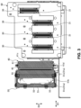
- Figs. 2 and 3 are views each illustrating an arrangement example of the head 30, the duct 40, and the light irradiation device 50.
- Fig. 2 is a view of a carriage 60 as viewed from the side
- Fig. 3 is a view of the carriage 60 as viewed from below.
- the head 30, the duct 40, and the light irradiation device 50 are mounted on the carriage 60 and arranged side by side in the main scanning direction D1.
- the head 30, the duct 40, and the light irradiation device 50 move integrally with the carriage 60 in the main scanning direction D1.
- a plurality of the heads 30 are arranged in the main scanning direction D1.
- Each of the heads 30 has a nozzle face 31 facing the mounting face 11a.
- the nozzle face 31 has, for example, a planar shape.
- the nozzle face 31 is provided with a plurality of nozzles for ejecting ink, which are not illustrated.
- the ink may include ultraviolet-curable ink.
- Examples of type of the ultraviolet-curable ink which can appropriately be used may include white ink, coloring ink of cyan (C), magenta (M), yellow (Y), and black (K), etc., and transparent ink, according to a color of an image to be formed on the medium M.
- the head 30 is electrically connected to a control unit CONT (see Fig. 1 ), and driving of the head 30 is controlled by the control unit CONT.
- the head 30 ejects the ink toward the medium M mounted on the mounting face 11a, while being reciprocated along the main scanning direction D1 by the movement of the carriage
- the light irradiation device 50 irradiates the ultraviolet-curable ink ejected on the medium M with an ultraviolet light.
- the light irradiation device 50 consists of, for example, an LED module capable of radiating ultraviolet light.
- the light irradiation device 50 is mounted on the carriage 60, and capable of reciprocating in the main scanning direction D1 along with movement of the carriage 60 along the main scanning direction D1.
- the light irradiation device 50 is electrically connected to the control unit CONT (see Fig. 1 ), and driving of the head 30 is controlled by the control unit CONT.
- the light irradiation device 50 has a housing 51.
- the housing 51 is provided with an irradiation face 51a facing the mounting face 11a.
- the irradiation face 51a has, for example, a planar shape.
- the irradiation face 51a is inclined so as to have an end portion on the head 30 side positioned lower than an end portion on the opposite side to the head 30, in the main scanning direction D1. That is, the irradiation face 51a is inclined so as to face opposite to the head 30.
- the irradiation face 51a is provided with a light-emission area 51b.
- the light-emission area 51b is an opening area provided to a part of the irradiation face 51a.
- the light-emission area 51b is arranged in the center portion of the irradiation face 51a in the main scanning direction D1, so as to extend in the medium transporting direction D2.
- the light-emission area 51b irradiates the mounting face 11a with an ultraviolet light.
- a plurality of light sources 52 are disposed in the housing 51.
- the plurality of light sources 52 are arranged in a matrix-like state on a substrate 53 in the light-emission area 51b.
- the plurality of light sources 52 are provided overlapping the light-emission area 51b when viewed from the vertical direction.
- the plurality of light sources 52 are, for example, LED chips, and are arranged in a state where light emitting faces thereof are directed to the side of the light-emission area 51b (lower side in the vertical direction).
- a cooling fan 54 that cools the plurality of light sources 52 and the substrate 53 (see Fig. 3 ).
- the cooling fan 54 is disposed above the substrate 53.
- the cooling fan 54 sprays the air toward the substrate 53 side.
- an upper side of the cooling fan 54 inside the housing 51 namely, a space 51K on the opposite side to the substrate 53 has a negative pressure.
- an electrostatic flocking part 55 is arranged in an outer area 51c of the irradiation face 51a excluding the light-emission area 51b.
- the electrostatic flocking part 55 is provided over the entire area of the outer area 51c.
- the electrostatic flocking part 55 is formed using a material, for example, nylon.
- the electrostatic flocking part 55 is formed, for example, by applying an adhesive to the entire face of the outer area 51c and attaching a flocking material in a form of short fibers thereto, for example, with a direct-current (DC) voltage.
- the dimension in the longitudinal direction (vertical direction) of the flocking material constituting the electrostatic flocking part 55 may be, for example, 0.1 mm to 3.0 mm, and preferably 0.2 mm to 1.0 mm, approximately.
- the duct 40 is arranged between the head 30 and the light irradiation device 50 in the main scanning direction D1.
- the duct 40 has a tube member 41.
- the tube member 41 has a first end portion 41a on the upper side and a second end portion 41b on the lower side, in the vertical direction.
- the first end portion 41a is attached to an upper portion of the housing 51 and communicates with the space 51K inside the housing 51. That is, the first end portion 41a is connected to the space 51K inside the housing 51 where a negative pressure is formed by the cooling fan 54.
- the second end portion 41b of the tube member 41 has a bottom face 41d facing the mounting face 11a and a suction port 41c provided on the upper side of the bottom face 41d and opens toward the head 30 side.
- a mist-state an ink mist
- the duct 40 sucks the mist-state ink (the ink mist) from the suction port 41c.
- an electrostatic flocking part 45 is arranged on the bottom face 41d of the second end portion 41b.
- the electrostatic flocking part 45 is provided over the entire area of the bottom face 41d.
- the electrostatic flocking part 45 is formed by using a material, for example, nylon, similarly as the electrostatic flocking part 55.
- the electrostatic flocking part 45 is formed, for example, by applying an adhesive to the entire face of the bottom face 41d and attaching a flocking material in a form of short fibers thereto, for example, with a DC voltage.
- the dimension in the longitudinal direction of the flocking material constituting the electrostatic flocking part 45 may be, for example, 0.1 mm to 3.0 mm, and preferably 0.2 mm to 1.0 mm, approximately.
- the duct 40 has an inclination adjustment unit 42.
- the inclination adjustment unit 42 may consist of a connecting member that connects the second end portion 41b to a portion above the second end portion 41b of the tube member 41.
- the second end portion 41b is rotatable about the connecting member by applying a force of a certain degree or more (see the dash-dotted lines in Fig. 4 ).
- the inclination adjustment unit 42 allows the second end portion 41b to have an inclination adjusted with respect to the vertical line direction.
- By adjusting inclination of the second end portion 41b of the duct 40 it is possible to change opening direction of the suction port 41c.
- inclination of the second end portion 41b By adjusting inclination of the second end portion 41b, inclination of the bottom face 41d with respect to the mounting face 11a is changed.
- the duct 40 is capable of adjusting inclination of the second end portion 41b such that the suction port 41c has an opening direction downward obliquely toward the head 30 side.
- the bottom face 41d is inclined so as to have an end portion on the head 30 side in the main scanning direction D1 positioned lower than an end portion on the opposite side to the head 30. That is, the bottom face 41d is inclined so as to be directed opposite to the head 30.
- the printing device 100 is set in a state, in advance, that the medium M is mounted on the mounting face 11a of the medium supporting unit 11.
- the control unit CONT moves the carriage 60 in the main scanning direction D1.
- the control unit CONT causes the head 30 to eject ink in conjunction with the movement of the carriage 60, and causes the light irradiation device 50 to emit an ultraviolet light.
- the control unit CONT operates the cooling fan 54 of the light irradiation device 50.
- the ink adheres to the medium M, and the adhered ink is irradiated with the ultraviolet light.
- ink mist floating between the head 30 and the medium M or the mounting face 11a is sucked from the suction port 41c of the duct 40.
- the control unit CONT repeats the operation, while moving the medium M in the medium transporting direction D2. By this control, an image is formed on the medium M.
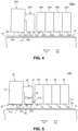
- Fig. 4 is a view illustrating an example of operation of a printing device according to a comparative example.
- Fig. 4 illustrates a state in which a medium M is mounted on a mounting face 16a of a medium supporting unit 16, in a printing device 100A according to the comparative example.
- a component LA traveling toward a head 30A side that is a part of ultraviolet light radiated from a light irradiation device 50A, is reflected by the medium M.
- the reflected ultraviolet light LA sometimes reaches an outer area 56c of a light irradiation device 50A.
- the ultraviolet light LA which reached the outer area 56c is reflected by the outer area 56c, and this reflected ultraviolet light LA is reflected by the medium M again and travels toward the head 30A side, sometimes.
- the ultraviolet light LA which irradiated the medium M is reflected between the medium M and the outer area 56c repeatedly, to travel toward the head 30A side.
- the ultraviolet light LA further travels toward the head 30A side, similarly by being reflected repeatedly between the medium M and a bottom face 46d of a duct 40.
- the ultraviolet light LA radiated from the light irradiation device 50A travels toward the head 30A side, and reaches a nozzle face 31A of the head 30A, as a stray light.
- An ink held in the nozzle face 31A can be cured by being irradiated with the stray light.
- Fig. 5 is a view illustrating an example of operation of a printing device according to the present embodiment.
- Fig. 5 shows a state in which the medium M is mounted on the mounting face 11a of the medium supporting unit 11, in the printing device 100 according to the present embodiment.
- the electrostatic flocking part 55 is provided in the outer area 51c of the housing 51 of the light irradiation device 50.
- the electrostatic flocking part 55 absorbs at least a part of the ultraviolet light L. Therefore, it is possible to inhibit the ultraviolet light L which has reached the outer area 51c from being reflected by the outer area 51c.
- the electrostatic flocking part 55 is capable of attenuating the ultraviolet light L while the ultraviolet light L repeats reflection between the outer area 51c and the medium M. This allows inhibiting the stray light of the ultraviolet light L from traveling toward the head 30 side, to reach the nozzle face 31.
- the irradiation face 51a of the light irradiation device 50 is inclined so as to be directed opposite to the head 30. This configuration allows inhibiting the ultraviolet light L from being reflected toward the head 30 side by the outer area 51c of the irradiation face 51a.
- the bottom face 41d of the duct 40 positioned between the light irradiation device 50 and the head 30 in the main scanning direction D1 is also provided with the electrostatic flocking part 45.
- the electrostatic flocking part 45 absorbs at least a part of the ultraviolet light L that has reached the bottom face 41d of the duct 40. This allows inhibiting the bottom face 41d of the duct 40 from reflecting the ultraviolet light L that has reached the bottom face 41d.
- the electrostatic flocking part 45 is capable of attenuating the ultraviolet light L while the ultraviolet light L repeats reflection between the bottom face 41d and the medium M. This allows inhibiting the stray light of the ultraviolet light L from reaching the head 30.
- a printing device 100 is equipped with, for example, the following configuration.
- the present invention was described by describing the configuration in which the electrostatic flocking part 55 is formed over the entire face of the outer area 51c of the irradiation face 51a in the light irradiation device 50, as an example.
- the present invention is not limited thereto.
- it could be a configuration in which the electrostatic flocking part 55 is provided only to an area on the head 30 side with respect to the light-emission area 51b in the main scanning direction D1 of the outer area 51c.
- the present invention was described by describing the configuration in which the duct 40 and the light irradiation device 50 are respectively provided with the electrostatic flocking parts 45 and 55, as an example.
- the present invention is not limited thereto.
- it could be a configuration in which either the electrostatic flocking part 45 or the electrostatic flocking part 55 is not provided.
- the facing portion facing the mounting face 11a, between the light-emission area 51b and the head 30 was described by describing the bottom face 41d of the duct 40 and the outer area 51c of the light irradiation device 50 as examples.
- the present invention is not limited thereto. It is also possible to dispose another configuration facing the mounting face 11a, between the light-emission area 51b and the head 30. In this case, it is possible to arrange the electrostatic flocking part in at least a part of the facing portion facing the mounting face 11a of the another configuration.
- the present invention was described by describing the configuration in which the duct 40 is arranged between the head 30 and the light irradiation device 50, as an example.
- the present invention is not limited thereto.
- the description of the above embodiment may be applied also to a configuration in which the duct 40 is not arranged between the head 30 and the light irradiation device 50.
- the present invention was described by describing the configuration in which the light irradiation device 50 is disposed only on one side of the main scanning direction D1 with respect to the head 30, as an example.
- the present invention is not limited thereto. It could be a configuration in which the light irradiation device 50 is disposed only on the other side than the side in the above-described embodiment in the main scanning direction D1 with respect to the head 30, or could be a configuration in which the light irradiation device 50 is disposed on both sides in the main scanning direction D1 with respect to the head 30.
- the present invention was described by describing the configuration in which the electrostatic flocking part is not disposed on the head 30, as an example.
- the present invention is not limited thereto. It could be a configuration in which the electrostatic flocking part is arranged between the end portion and the nozzle face 31 in the main scanning direction D 1 of the head 30.
Landscapes
- Health & Medical Sciences (AREA)
- General Health & Medical Sciences (AREA)
- Toxicology (AREA)
- Ink Jet (AREA)
Abstract
Description
- The present invention relates to a printing device.
- Printing devices of ink curing type have been known (see, for example, Patent Literature 1). The printing devices eject ultraviolet-curable ink, for example, from a head to a medium to be printed. The printing devices cure the ejected ink by irradiating the ink with ultraviolet light from a light irradiation device.
- Patent Literature 1:
JP 2004-314304 A - In the printing device as described above, a part of the ultraviolet light radiated from the light irradiation device can become a stray light. For example, a part of the radiated ultraviolet light is reflected by a medium, and the ultraviolet light reflected by the medium is reflected by a surface facing the medium, of the light irradiation device. The ultraviolet light can reach the head as a result of repeating such reflections. When the head is irradiated with such a stray light, ink in the head is cured, and can cause an ink clogging.
- The present invention has been made in view of the above, and an object thereof is to provide a printing device capable of suppressing generation of stray light.
- A printing device according to the present invention is equipped with: a head configured to eject ink which cures by being irradiated with light, toward a mounting face on which a medium is mounted; a light irradiation device that is arranged side by side with the head and irradiates the mounting face with a light which cures the ink from a light-emission area disposed on an irradiation face facing the mounting face; and an electrostatic flocking part arranged in at least a part of a facing portion facing the mounting face between the light-emission area and the head.
- In the printing device, the electrostatic flocking part is provided over the entire area on the head side of the light-emission area of the irradiation face.
- In the printing device, the irradiation face has a planar shape, and disposed inclined so as to have an end portion on the head side positioned lower than an end portion on the opposite side to the head.
- The printing device is further equipped with a duct arranged between the head and the light irradiation device, that has a suction port for sucking mist generated from the head.
- In the printing device, the light irradiation device has a light source that emits the light and a cooling fan that cools the light source, and the duct is connected to a negative pressure side of the cooling fan.
- In the printing device, the electrostatic flocking part is arranged in a portion of the duct facing the mounting face.
- According to the present invention, it is possible to suppress generation of stray light.
-
-
Fig. 1 is a perspective view illustrating an example of a printing device according to the present embodiment. -
Fig. 2 is a view illustrating an arrangement example of the head, the duct, and the light irradiation device. -
Fig. 3 is a view illustrating an arrangement example of the head, the duct, and the light irradiation device. -
Fig. 4 is a view illustrating an example of operation of a printing device according to a comparative example. -
Fig. 5 is a view illustrating an example of operation of a printing device according to the present embodiment. - Hereinafter, embodiments of a printing device according to the present invention will be described with reference to the drawings. It should be noted that each of the embodiments shows one aspect of the present invention as an example, and does not limit the present invention. Constituent elements in the following embodiments include those easily replaceable by a person skilled in the art or those substantially the same with each other.
-
Fig. 1 is a perspective view illustrating an example of aprinting device 100 according to the present embodiment. As shown inFig. 1 , theprinting device 100 is an inkjet type printing device, and is equipped with amain body unit 10, anink supply unit 20, ahead 30, aduct 40, and alight irradiation device 50. Examples ofsuch printing device 100 may include those of various types, for example, a vertical type or a flat bed type. - The
main body unit 10 has a medium supportingunit 11 and amedium driving unit 12. Themedium supporting unit 11 supports a medium M on a mountingface 11a. Themedium driving unit 12 moves the medium M in a medium transporting direction D2. The medium transporting direction D2 is a direction orthogonal to a main scanning direction D1. The main scanning direction D1 and the medium transporting direction D2 are directions orthogonal to the vertical line direction. - The
ink supply unit 20 has, for example, an ink container which is not illustrated. An ink contained in the ink container is supplied to thehead 30 via a supply path which is not illustrated, and is ejected as droplets from thehead 30. -
Figs. 2 and3 are views each illustrating an arrangement example of thehead 30, theduct 40, and thelight irradiation device 50.Fig. 2 is a view of acarriage 60 as viewed from the side, andFig. 3 is a view of thecarriage 60 as viewed from below. As illustrated inFigs. 2 and3 , thehead 30, theduct 40, and thelight irradiation device 50 are mounted on thecarriage 60 and arranged side by side in the main scanning direction D1. Thehead 30, theduct 40, and thelight irradiation device 50 move integrally with thecarriage 60 in the main scanning direction D1. - For example, a plurality of the
heads 30 are arranged in the main scanning direction D1. Each of theheads 30 has anozzle face 31 facing themounting face 11a. Thenozzle face 31 has, for example, a planar shape. Thenozzle face 31 is provided with a plurality of nozzles for ejecting ink, which are not illustrated. Examples of the ink may include ultraviolet-curable ink. Examples of type of the ultraviolet-curable ink which can appropriately be used may include white ink, coloring ink of cyan (C), magenta (M), yellow (Y), and black (K), etc., and transparent ink, according to a color of an image to be formed on the medium M. Thehead 30 is electrically connected to a control unit CONT (seeFig. 1 ), and driving of thehead 30 is controlled by the control unit CONT. Thehead 30 ejects the ink toward the medium M mounted on themounting face 11a, while being reciprocated along the main scanning direction D1 by the movement of thecarriage 60. - The
light irradiation device 50 irradiates the ultraviolet-curable ink ejected on the medium M with an ultraviolet light. Thelight irradiation device 50 consists of, for example, an LED module capable of radiating ultraviolet light. Thelight irradiation device 50 is mounted on thecarriage 60, and capable of reciprocating in the main scanning direction D1 along with movement of thecarriage 60 along the main scanning direction D1. Thelight irradiation device 50 is electrically connected to the control unit CONT (seeFig. 1 ), and driving of thehead 30 is controlled by the control unit CONT. - As illustrated in
Fig. 2 , thelight irradiation device 50 has ahousing 51. Thehousing 51 is provided with anirradiation face 51a facing themounting face 11a. Theirradiation face 51a has, for example, a planar shape. Theirradiation face 51a is inclined so as to have an end portion on thehead 30 side positioned lower than an end portion on the opposite side to thehead 30, in the main scanning direction D1. That is, theirradiation face 51a is inclined so as to face opposite to thehead 30. - As illustrated in
Fig. 3 , theirradiation face 51a is provided with a light-emission area 51b. The light-emission area 51b is an opening area provided to a part of theirradiation face 51a. For example, the light-emission area 51b is arranged in the center portion of theirradiation face 51a in the main scanning direction D1, so as to extend in the medium transporting direction D2. The light-emission area 51b irradiates the mountingface 11a with an ultraviolet light. A plurality oflight sources 52 are disposed in thehousing 51. The plurality oflight sources 52 are arranged in a matrix-like state on asubstrate 53 in the light-emission area 51b. The plurality oflight sources 52 are provided overlapping the light-emission area 51b when viewed from the vertical direction. The plurality oflight sources 52 are, for example, LED chips, and are arranged in a state where light emitting faces thereof are directed to the side of the light-emission area 51b (lower side in the vertical direction). - As illustrated in
Fig. 2 , inside of thehousing 51 is provided with a coolingfan 54 that cools the plurality oflight sources 52 and the substrate 53 (seeFig. 3 ). The coolingfan 54 is disposed above thesubstrate 53. The coolingfan 54 sprays the air toward thesubstrate 53 side. When the coolingfan 54 operates, an upper side of the coolingfan 54 inside thehousing 51, namely, aspace 51K on the opposite side to thesubstrate 53 has a negative pressure. - As illustrated in
Fig. 3 , an electrostatic flockingpart 55 is arranged in anouter area 51c of theirradiation face 51a excluding the light-emission area 51b. The electrostatic flockingpart 55 is provided over the entire area of theouter area 51c. The electrostatic flockingpart 55 is formed using a material, for example, nylon. The electrostatic flockingpart 55 is formed, for example, by applying an adhesive to the entire face of theouter area 51c and attaching a flocking material in a form of short fibers thereto, for example, with a direct-current (DC) voltage. The dimension in the longitudinal direction (vertical direction) of the flocking material constituting the electrostatic flockingpart 55 may be, for example, 0.1 mm to 3.0 mm, and preferably 0.2 mm to 1.0 mm, approximately. - The
duct 40 is arranged between thehead 30 and thelight irradiation device 50 in the main scanning direction D1. Theduct 40 has atube member 41. As illustrated inFig. 2 , thetube member 41 has afirst end portion 41a on the upper side and asecond end portion 41b on the lower side, in the vertical direction. Thefirst end portion 41a is attached to an upper portion of thehousing 51 and communicates with thespace 51K inside thehousing 51. That is, thefirst end portion 41a is connected to thespace 51K inside thehousing 51 where a negative pressure is formed by the coolingfan 54. Thesecond end portion 41b of thetube member 41 has abottom face 41d facing the mountingface 11a and asuction port 41c provided on the upper side of thebottom face 41d and opens toward thehead 30 side. As an ink is ejected from thehead 30, the ink in a mist-state (an ink mist) sometimes floats around thehead 30. Theduct 40 sucks the mist-state ink (the ink mist) from thesuction port 41c. - As illustrated in
Fig. 3 , an electrostatic flockingpart 45 is arranged on thebottom face 41d of thesecond end portion 41b. The electrostatic flockingpart 45 is provided over the entire area of thebottom face 41d. The electrostatic flockingpart 45 is formed by using a material, for example, nylon, similarly as the electrostatic flockingpart 55. The electrostatic flockingpart 45 is formed, for example, by applying an adhesive to the entire face of thebottom face 41d and attaching a flocking material in a form of short fibers thereto, for example, with a DC voltage. The dimension in the longitudinal direction of the flocking material constituting the electrostatic flockingpart 45 may be, for example, 0.1 mm to 3.0 mm, and preferably 0.2 mm to 1.0 mm, approximately. - The
duct 40 has aninclination adjustment unit 42. For example, theinclination adjustment unit 42 may consist of a connecting member that connects thesecond end portion 41b to a portion above thesecond end portion 41b of thetube member 41. For example, thesecond end portion 41b is rotatable about the connecting member by applying a force of a certain degree or more (see the dash-dotted lines inFig. 4 ). In theduct 40, theinclination adjustment unit 42 allows thesecond end portion 41b to have an inclination adjusted with respect to the vertical line direction. By adjusting inclination of thesecond end portion 41b of theduct 40, it is possible to change opening direction of thesuction port 41c. By adjusting inclination of thesecond end portion 41b, inclination of thebottom face 41d with respect to the mountingface 11a is changed. - For example, the
duct 40 is capable of adjusting inclination of thesecond end portion 41b such that thesuction port 41c has an opening direction downward obliquely toward thehead 30 side. In this case, it is possible to efficiently suck the ink mist from thehead 30 side. Additionally, in this case, thebottom face 41d is inclined so as to have an end portion on thehead 30 side in the main scanning direction D1 positioned lower than an end portion on the opposite side to thehead 30. That is, thebottom face 41d is inclined so as to be directed opposite to thehead 30. - Next, an example of operation of the
printing device 100 configured as described above will be described. Theprinting device 100 is set in a state, in advance, that the medium M is mounted on the mountingface 11a of themedium supporting unit 11. - In this state, for example, when there is an instruction to perform a printing operation from an external device, the control unit CONT moves the
carriage 60 in the main scanning direction D1. The control unit CONT causes thehead 30 to eject ink in conjunction with the movement of thecarriage 60, and causes thelight irradiation device 50 to emit an ultraviolet light. In addition, the control unit CONT operates the coolingfan 54 of thelight irradiation device 50. By this operation, the ink adheres to the medium M, and the adhered ink is irradiated with the ultraviolet light. In addition, ink mist floating between thehead 30 and the medium M or the mountingface 11a is sucked from thesuction port 41c of theduct 40. The control unit CONT repeats the operation, while moving the medium M in the medium transporting direction D2. By this control, an image is formed on the medium M. -
Fig. 4 is a view illustrating an example of operation of a printing device according to a comparative example.Fig. 4 illustrates a state in which a medium M is mounted on a mountingface 16a of amedium supporting unit 16, in aprinting device 100A according to the comparative example. - In this state, for example, a component LA traveling toward a
head 30A side, that is a part of ultraviolet light radiated from alight irradiation device 50A, is reflected by the medium M. The reflected ultraviolet light LA sometimes reaches anouter area 56c of alight irradiation device 50A. The ultraviolet light LA which reached theouter area 56c is reflected by theouter area 56c, and this reflected ultraviolet light LA is reflected by the medium M again and travels toward thehead 30A side, sometimes. - In this manner, the ultraviolet light LA which irradiated the medium M is reflected between the medium M and the
outer area 56c repeatedly, to travel toward thehead 30A side. The ultraviolet light LA further travels toward thehead 30A side, similarly by being reflected repeatedly between the medium M and abottom face 46d of aduct 40. Thus, there is a possibility that the ultraviolet light LA radiated from thelight irradiation device 50A travels toward thehead 30A side, and reaches anozzle face 31A of thehead 30A, as a stray light. An ink held in thenozzle face 31A can be cured by being irradiated with the stray light. -
Fig. 5 is a view illustrating an example of operation of a printing device according to the present embodiment.Fig. 5 shows a state in which the medium M is mounted on the mountingface 11a of themedium supporting unit 11, in theprinting device 100 according to the present embodiment. - In the present embodiment, the electrostatic flocking
part 55 is provided in theouter area 51c of thehousing 51 of thelight irradiation device 50. Thus, when a component L of ultraviolet light radiated from thelight irradiation device 50, which is reflected by the medium M has reached theouter area 51c, the electrostatic flockingpart 55 absorbs at least a part of the ultraviolet light L. Therefore, it is possible to inhibit the ultraviolet light L which has reached theouter area 51c from being reflected by theouter area 51c. Thus, the electrostatic flockingpart 55 is capable of attenuating the ultraviolet light L while the ultraviolet light L repeats reflection between theouter area 51c and the medium M. This allows inhibiting the stray light of the ultraviolet light L from traveling toward thehead 30 side, to reach thenozzle face 31. - In addition, the
irradiation face 51a of thelight irradiation device 50 is inclined so as to be directed opposite to thehead 30. This configuration allows inhibiting the ultraviolet light L from being reflected toward thehead 30 side by theouter area 51c of theirradiation face 51a. - In the present embodiment, the
bottom face 41d of theduct 40 positioned between thelight irradiation device 50 and thehead 30 in the main scanning direction D1 is also provided with the electrostatic flockingpart 45. By this configuration, the electrostatic flockingpart 45 absorbs at least a part of the ultraviolet light L that has reached thebottom face 41d of theduct 40. This allows inhibiting thebottom face 41d of theduct 40 from reflecting the ultraviolet light L that has reached thebottom face 41d. Accordingly, the electrostatic flockingpart 45 is capable of attenuating the ultraviolet light L while the ultraviolet light L repeats reflection between thebottom face 41d and the medium M. This allows inhibiting the stray light of the ultraviolet light L from reaching thehead 30. Besides, it is also possible to direct thebottom face 41d opposite to thehead 30, by adjusting inclination of thesecond end portion 41b side of thetube member 41. This allows inhibiting the ultraviolet light L from being reflected toward thehead 30 side by thebottom face 41d. - As described above, a
printing device 100 according to the present embodiment is equipped with, for example, the following configuration. - (1) The
printing device 100 is equipped with ahead 30, alight irradiation device 50, and electrostatic flockingparts head 30 ejects an ink which cures by being irradiated with ultraviolet light (light) toward a mountingface 11a on which a medium M is mounted. Thelight irradiation device 50 is arranged side by side with thehead 30, and irradiates the mountingface 11a with an ultraviolet light (a light) which cures ink from a light-emission area 51b disposed on anirradiation face 51a facing the mountingface 11a. The electrostatic flockingparts face 11a (theirradiation face 51a and abottom face 41d) between the light-emission area 51b and thehead 30 in a main scanning direction D1.
According to this configuration, when an ultraviolet light L reflected by the medium M has reached the facing portion facing the mountingface 11a (theirradiation face 51a or thebottom face 41d), a part of the ultraviolet light is absorbed in the electrostatic flockingpart head 30 as a stray light. - (2) In the
printing device 100 according to the present embodiment, the electrostatic flockingpart 55 may be provided over the entire area of thehead 30 side of the light-emission area 51b of theirradiation face 51a. As an example, the electrostatic flockingpart 55 may be provided on the entire area of theouter area 51c excluding the light-emission area 51b of theirradiation face 51a.
According to this configuration, the electrostatic flockingpart 55 is capable of absorbing and attenuating the ultraviolet light L radiated from the light-emission area 51b of theirradiation face 51a, which is then reflected by the medium M, and has reached the portion on thehead 30 side of theouter area 51c. In addition, since the electrostatic flockingpart 55 is formed on the entire area on thehead 30 side from the light-emission area 51b of theouter area 51c, it is not necessary to apply a mask or the like, which allows forming the electrostatic flockingpart 55 in a small number of steps. - (3) In the
printing device 100 according to the present embodiment, theirradiation face 51a has a planar shape. Theirradiation face 51a is arranged inclined so as to have an end portion on thehead 30 side in the main scanning direction D1 positioned lower than an end portion on the opposite side to thehead 30. This configuration allows inhibiting the ultraviolet light L that has reached theirradiation face 51a from being reflected toward thehead 30 side. - (4) The
printing device 100 according to the present embodiment is equipped with aduct 40. Theduct 40 is arranged between thehead 30 and thelight irradiation device 50 in the main scanning direction D1. Theduct 40 has asuction port 41c for sucking the mist generated from thehead 30. According to this configuration, theduct 40 is capable of sucking ink mist, and thus it is possible to inhibit the ink mist from adhering to the electrostatic flockingparts part - (5) In the
printing device 100 according to the present embodiment, thelight irradiation device 50 has alight source 52 that emits light and a coolingfan 54 that cools thelight source 52. Theduct 40 is connected to a negative pressure side of the coolingfan 54. According to this configuration, it is possible to suck the ink mist efficiently utilizing a negative pressure generated by the coolingfan 54. - (6) In the
printing device 100 according to the present embodiment, the electrostatic flockingpart 45 is arranged on thebottom face 41d of theduct 40, that is a portion facing the mountingface 11a. According to this configuration, the electrostatic flockingpart 45 is capable of absorbing a part of the ultraviolet light L reaching thebottom face 41d of theduct 40. - The technical scope of the present invention is not limited to the above embodiments, and may appropriately be changed without departing from gist of the present invention. For example, in the above embodiment, the present invention was described by describing the configuration in which the electrostatic flocking
part 55 is formed over the entire face of theouter area 51c of theirradiation face 51a in thelight irradiation device 50, as an example. However, the present invention is not limited thereto. For example, it could be a configuration in which the electrostatic flockingpart 55 is provided only to an area on thehead 30 side with respect to the light-emission area 51b in the main scanning direction D1 of theouter area 51c. - In the above embodiment, the present invention was described by describing the configuration in which the
duct 40 and thelight irradiation device 50 are respectively provided with the electrostatic flockingparts part 45 or the electrostatic flockingpart 55 is not provided. - In the above embodiment, the facing portion facing the mounting
face 11a, between the light-emission area 51b and thehead 30 was described by describing thebottom face 41d of theduct 40 and theouter area 51c of thelight irradiation device 50 as examples. However, the present invention is not limited thereto. It is also possible to dispose another configuration facing the mountingface 11a, between the light-emission area 51b and thehead 30. In this case, it is possible to arrange the electrostatic flocking part in at least a part of the facing portion facing the mountingface 11a of the another configuration. - In the above embodiment, the present invention was described by describing the configuration in which the
duct 40 is arranged between thehead 30 and thelight irradiation device 50, as an example. However, the present invention is not limited thereto. For example, the description of the above embodiment may be applied also to a configuration in which theduct 40 is not arranged between thehead 30 and thelight irradiation device 50. - In the above embodiment, the present invention was described by describing the configuration in which the
light irradiation device 50 is disposed only on one side of the main scanning direction D1 with respect to thehead 30, as an example. However, the present invention is not limited thereto. It could be a configuration in which thelight irradiation device 50 is disposed only on the other side than the side in the above-described embodiment in the main scanning direction D1 with respect to thehead 30, or could be a configuration in which thelight irradiation device 50 is disposed on both sides in the main scanning direction D1 with respect to thehead 30. - In the above embodiment, the present invention was described by describing the configuration in which the electrostatic flocking part is not disposed on the
head 30, as an example. However, the present invention is not limited thereto. It could be a configuration in which the electrostatic flocking part is arranged between the end portion and thenozzle face 31 in the main scanning direction D 1 of thehead 30. -
- D1 Main
- scanning direction
- D2
- Medium moving direction
- M
- Medium
- CONT
- Control unit
- 10
- Main body unit
- 11
- Medium supporting unit
- 11a
- Mounting face
- 12
- Medium driving unit
- 20
- Ink supply unit
- 30
- Head
- 31
- Nozzle face
- 40
- Duct
- 41
- Tube member
- 41a
- First end portion
- 41b
- Second end portion
- 41c
- Suction port
- 41d
- Bottom face
- 45, 55
- Electrostatic flocking part
- 50
- Light irradiation device
- 54
- Housing
- 51a
- Irradiation face
- 51b
- Light-emission area
- 51c
- Outer area
- 52
- Light source
- 53
- Substrate
- 54
- Cooling fan
- 60
- Carriage
- 100
- Printing device
Claims (6)
- A printing device comprising:a head configured to eject an ink that cures by being irradiated with light, toward a mounting face on which a medium is mounted;a light irradiation device that is arranged side by side with the head and that is configured to irradiate the mounting face with light for curing the ink from a light-emission area disposed on an irradiation face facing the mounting face; andan electrostatic flocking part arranged in at least a part of a facing portion facing the mounting face between the light-emission area and the head.
- The printing device as set forth in claim 1, wherein the electrostatic flocking part is provided over an entire area of the head side of the light-emission area of the irradiation face.
- The printing device as set forth in claim 1 or 2, wherein the irradiation face has a planar shape, and is inclined so as to have an end portion on the head side that is positioned lower than an end portion on a side opposite to the head.
- The printing device as set forth in any one of claims 1 to 3, further comprising a duct that is arranged between the head and the light irradiation device and comprises a suction port for sucking a mist generated from the head.
- The printing device as set forth in claim 4, wherein the light irradiation device comprises a light source configured to emit light and a cooling fan configured to cool the light source, and the duct is connected to a negative pressure side of the cooling fan.
- The printing device as set forth in claim 4 or 5, wherein the electrostatic flocking part is arranged in a portion facing the mounting face, of the duct.
Applications Claiming Priority (2)
| Application Number | Priority Date | Filing Date | Title |
|---|---|---|---|
| JP2021181124A JP2023069339A (en) | 2021-11-05 | 2021-11-05 | printer |
| PCT/JP2022/040752 WO2023080117A1 (en) | 2021-11-05 | 2022-10-31 | Printing device |
Publications (2)
| Publication Number | Publication Date |
|---|---|
| EP4427939A1 true EP4427939A1 (en) | 2024-09-11 |
| EP4427939A4 EP4427939A4 (en) | 2025-02-26 |
Family
ID=86241102
Family Applications (1)
| Application Number | Title | Priority Date | Filing Date |
|---|---|---|---|
| EP22889937.3A Pending EP4427939A4 (en) | 2021-11-05 | 2022-10-31 | PRINTING DEVICE |
Country Status (5)
| Country | Link |
|---|---|
| US (1) | US20250269665A1 (en) |
| EP (1) | EP4427939A4 (en) |
| JP (1) | JP2023069339A (en) |
| CN (1) | CN118139746A (en) |
| WO (1) | WO2023080117A1 (en) |
Family Cites Families (13)
| Publication number | Priority date | Publication date | Assignee | Title |
|---|---|---|---|---|
| JP2004314304A (en) | 2002-03-27 | 2004-11-11 | Konica Minolta Holdings Inc | Ink-jet printer |
| JP4617670B2 (en) * | 2003-12-25 | 2011-01-26 | コニカミノルタエムジー株式会社 | Image recording device |
| JP5251479B2 (en) * | 2008-12-16 | 2013-07-31 | セイコーエプソン株式会社 | Recording device |
| JP2010234818A (en) * | 2010-07-30 | 2010-10-21 | Konica Minolta Medical & Graphic Inc | Image recorder |
| CN103510674A (en) * | 2012-06-29 | 2014-01-15 | 无锡新大中薄板有限公司 | Method for manufacturing flocking hot galvanizing spraying decoration plate |
| US9162444B2 (en) * | 2012-11-30 | 2015-10-20 | Seiko Epson Corporation | Printing apparatus |
| JP6003617B2 (en) * | 2012-12-19 | 2016-10-05 | セイコーエプソン株式会社 | Printing device |
| JP2014136314A (en) * | 2013-01-15 | 2014-07-28 | Seiko Epson Corp | Printer |
| JP2014184666A (en) * | 2013-03-25 | 2014-10-02 | Seiko Epson Corp | Image recording device |
| JP6198465B2 (en) * | 2013-05-28 | 2017-09-20 | 株式会社ミマキエンジニアリング | Inkjet recording device |
| JP6699437B2 (en) * | 2016-08-09 | 2020-05-27 | セイコーエプソン株式会社 | Recording device |
| JP6694353B2 (en) * | 2016-08-24 | 2020-05-13 | 株式会社ミマキエンジニアリング | inkjet printer |
| JP2020001296A (en) * | 2018-06-29 | 2020-01-09 | 武藤工業株式会社 | Light trap for ink jet printer and ultraviolet lamp |
-
2021
- 2021-11-05 JP JP2021181124A patent/JP2023069339A/en active Pending
-
2022
- 2022-10-31 US US18/703,717 patent/US20250269665A1/en active Pending
- 2022-10-31 WO PCT/JP2022/040752 patent/WO2023080117A1/en not_active Ceased
- 2022-10-31 EP EP22889937.3A patent/EP4427939A4/en active Pending
- 2022-10-31 CN CN202280071011.1A patent/CN118139746A/en active Pending
Also Published As
| Publication number | Publication date |
|---|---|
| EP4427939A4 (en) | 2025-02-26 |
| WO2023080117A1 (en) | 2023-05-11 |
| US20250269665A1 (en) | 2025-08-28 |
| CN118139746A (en) | 2024-06-04 |
| JP2023069339A (en) | 2023-05-18 |
Similar Documents
| Publication | Publication Date | Title |
|---|---|---|
| CN102355998B (en) | Ultraviolet irradiation unit | |
| US7762658B2 (en) | Ink jet printer | |
| JP2009226692A (en) | Inkjet printer | |
| JP5007675B2 (en) | Inkjet printing device | |
| JP2005186422A (en) | Image recorder | |
| JP2019069549A (en) | Printing device and printing method | |
| CN107825850B (en) | Ink jet head, ink jet recording apparatus, and method of manufacturing ink jet head | |
| US20250269665A1 (en) | Printing device | |
| CN111497438B (en) | Photo-curing type ink-jet printer | |
| JP7186665B2 (en) | inkjet printer | |
| CN101412316A (en) | Recording apparatus and liquid ejecting apparatus | |
| JP4400541B2 (en) | Pattern forming method and droplet discharge apparatus | |
| JP2004001326A (en) | Inkjet recording device | |
| KR100765402B1 (en) | Method for forming a pattern and liquid ejection apparatus | |
| JP5720768B2 (en) | Printing device | |
| JP5440656B2 (en) | Inkjet printing device | |
| JP7200752B2 (en) | Liquid ejection head and device for ejecting liquid | |
| JP2016016550A (en) | Cleaning device for droplet discharge part, cleaning method, droplet discharge device, and image formation device | |
| JP2021079613A (en) | Inkjet printer and control method of inkjet printer | |
| JP7428031B2 (en) | printing device | |
| JP2010111090A (en) | Liquid jetting apparatus | |
| JP2004001328A (en) | Inkjet recording device | |
| CN1944050A (en) | Method for forming a pattern and liquid ejection apparatus | |
| JP2016196125A (en) | Liquid ejecting head and liquid ejecting apparatus | |
| JP6310218B2 (en) | Inkjet printer |
Legal Events
| Date | Code | Title | Description |
|---|---|---|---|
| STAA | Information on the status of an ep patent application or granted ep patent |
Free format text: STATUS: THE INTERNATIONAL PUBLICATION HAS BEEN MADE |
|
| PUAI | Public reference made under article 153(3) epc to a published international application that has entered the european phase |
Free format text: ORIGINAL CODE: 0009012 |
|
| STAA | Information on the status of an ep patent application or granted ep patent |
Free format text: STATUS: REQUEST FOR EXAMINATION WAS MADE |
|
| 17P | Request for examination filed |
Effective date: 20240321 |
|
| AK | Designated contracting states |
Kind code of ref document: A1 Designated state(s): AL AT BE BG CH CY CZ DE DK EE ES FI FR GB GR HR HU IE IS IT LI LT LU LV MC ME MK MT NL NO PL PT RO RS SE SI SK SM TR |
|
| DAV | Request for validation of the european patent (deleted) | ||
| DAX | Request for extension of the european patent (deleted) | ||
| A4 | Supplementary search report drawn up and despatched |
Effective date: 20250127 |
|
| RIC1 | Information provided on ipc code assigned before grant |
Ipc: B41J 2/175 20060101ALN20250121BHEP Ipc: B41J 29/13 20060101ALI20250121BHEP Ipc: B41J 2/17 20060101ALI20250121BHEP Ipc: B41J 11/00 20060101ALI20250121BHEP Ipc: B41J 2/01 20060101AFI20250121BHEP |