EP4427903A1 - Tire molding mold and tire manufacturing method - Google Patents
Tire molding mold and tire manufacturing method Download PDFInfo
- Publication number
- EP4427903A1 EP4427903A1 EP22889607.2A EP22889607A EP4427903A1 EP 4427903 A1 EP4427903 A1 EP 4427903A1 EP 22889607 A EP22889607 A EP 22889607A EP 4427903 A1 EP4427903 A1 EP 4427903A1
- Authority
- EP
- European Patent Office
- Prior art keywords
- segment
- tire
- molding portion
- tread
- tread molding
- Prior art date
- Legal status (The legal status is an assumption and is not a legal conclusion. Google has not performed a legal analysis and makes no representation as to the accuracy of the status listed.)
- Granted
Links
Images







Classifications
-
- B—PERFORMING OPERATIONS; TRANSPORTING
- B29—WORKING OF PLASTICS; WORKING OF SUBSTANCES IN A PLASTIC STATE IN GENERAL
- B29D—PRODUCING PARTICULAR ARTICLES FROM PLASTICS OR FROM SUBSTANCES IN A PLASTIC STATE
- B29D30/00—Producing pneumatic or solid tyres or parts thereof
- B29D30/06—Pneumatic tyres or parts thereof (e.g. produced by casting, moulding, compression moulding, injection moulding, centrifugal casting)
- B29D30/0601—Vulcanising tyres; Vulcanising presses for tyres
- B29D30/0606—Vulcanising moulds not integral with vulcanising presses
- B29D30/0629—Vulcanising moulds not integral with vulcanising presses with radially movable sectors
-
- B—PERFORMING OPERATIONS; TRANSPORTING
- B29—WORKING OF PLASTICS; WORKING OF SUBSTANCES IN A PLASTIC STATE IN GENERAL
- B29C—SHAPING OR JOINING OF PLASTICS; SHAPING OF MATERIAL IN A PLASTIC STATE, NOT OTHERWISE PROVIDED FOR; AFTER-TREATMENT OF THE SHAPED PRODUCTS, e.g. REPAIRING
- B29C33/00—Moulds or cores; Details thereof or accessories therefor
- B29C33/02—Moulds or cores; Details thereof or accessories therefor with incorporated heating or cooling means
-
- B—PERFORMING OPERATIONS; TRANSPORTING
- B29—WORKING OF PLASTICS; WORKING OF SUBSTANCES IN A PLASTIC STATE IN GENERAL
- B29C—SHAPING OR JOINING OF PLASTICS; SHAPING OF MATERIAL IN A PLASTIC STATE, NOT OTHERWISE PROVIDED FOR; AFTER-TREATMENT OF THE SHAPED PRODUCTS, e.g. REPAIRING
- B29C35/00—Heating, cooling or curing, e.g. crosslinking or vulcanising; Apparatus therefor
- B29C35/02—Heating or curing, e.g. crosslinking or vulcanizing during moulding, e.g. in a mould
-
- B—PERFORMING OPERATIONS; TRANSPORTING
- B29—WORKING OF PLASTICS; WORKING OF SUBSTANCES IN A PLASTIC STATE IN GENERAL
- B29D—PRODUCING PARTICULAR ARTICLES FROM PLASTICS OR FROM SUBSTANCES IN A PLASTIC STATE
- B29D30/00—Producing pneumatic or solid tyres or parts thereof
- B29D30/06—Pneumatic tyres or parts thereof (e.g. produced by casting, moulding, compression moulding, injection moulding, centrifugal casting)
- B29D30/0601—Vulcanising tyres; Vulcanising presses for tyres
- B29D30/0606—Vulcanising moulds not integral with vulcanising presses
- B29D2030/0607—Constructional features of the moulds
-
- B—PERFORMING OPERATIONS; TRANSPORTING
- B29—WORKING OF PLASTICS; WORKING OF SUBSTANCES IN A PLASTIC STATE IN GENERAL
- B29D—PRODUCING PARTICULAR ARTICLES FROM PLASTICS OR FROM SUBSTANCES IN A PLASTIC STATE
- B29D30/00—Producing pneumatic or solid tyres or parts thereof
- B29D30/06—Pneumatic tyres or parts thereof (e.g. produced by casting, moulding, compression moulding, injection moulding, centrifugal casting)
- B29D30/0601—Vulcanising tyres; Vulcanising presses for tyres
- B29D30/0606—Vulcanising moulds not integral with vulcanising presses
- B29D30/0629—Vulcanising moulds not integral with vulcanising presses with radially movable sectors
- B29D2030/0631—Means for forcing adjacent mould sectors away one from another, e.g. using springs or the like, to create repulsive forces
Definitions
- the present disclosure relates to a mold for forming a tire and a tire production method.
- a circular tread molding portion for forming a tire tread is divided into a plurality of circumferentially aligned segments and it opens and closes due to radial movement of each segment (see, for example, Patent Literature 1 to 3).
- each segment moves radially outward while maintaining its posture with respect to the tire tread, so that the entire tread design surface, which is for molding the tread, of each segment is detached from the tread at the same time. Therefore, a large driving force is required to drive the segments until the segments are detached from the tire.
- the tread design surface of the segment must be detached from the tread, and protrusions of the segment corresponding to the design surface pattern of the tire must be pulled out therefrom. Therefore, when the tread design surface of the segment was detached from the tread, a large driving force was required to release the adhesion between the tread design surface and the tread. In addition, during the period until the segment is detached from the tire, due to the undercut resistance which is generated when the protrusions of the segment corresponding to the design surface pattern of the tire is pulled out therefrom, large driving force was required to drive the segment.
- This disclosure has been made in view of these circumstances, and its purpose is to provide a mold for forming a tire and a tire production method that can reduce the driving force required to drive the segment in the initial stage of releasing a tire from the mold.
- the mold for forming a tire in accordance with the present disclosure to achieve the above-mentioned purpose comprises:
- This disclosure can provide a mold for forming a tire and a tire production method that can reduce the driving force required to drive the segment in the initial stage of releasing a tire from a mold.
- a mold 1 for forming a tire in accordance with one embodiment of the present disclosure, illustrated in Figure 1 , is used to produce a tire 2 by molding a raw tire formed mainly of unvulcanized (pre-vulcanized) synthetic rubber into a predetermined shape while vulcanizing it.
- the tire 2 is a hollow tire made mainly of synthetic rubber, having a pair of sidewalls 2a and 2b and a tread 2c, and formed into a shape with an interior space filled with air, nitrogen or other gas.
- the mold 1 for forming a tire has a sidewall molding portion 10 and a tread molding portion 20.
- the sidewall molding portion 10 can, for example, consist of a circular lower sidewall molding portion 11 fixed to the upper surface of a lower container 3 and a circular upper sidewall molding portion 12 fixed to the lower surface of a upper container 4.
- the sidewall molding portion 10 can position (store) the circular tire 2 or a raw tire between the lower sidewall molding portion 11 and the upper sidewall molding portion 12 in an orientation where the center axis of the tire is coaxial with the center axis O of the sidewall molding portion 10.
- the lower sidewall molding portion 11 comprises a circular, upward-facing lower sidewall design surface 11a, centered on the central axis O.
- the lower sidewall design surface 11a can be used to mold the outer surface of one sidewall 2a of the tire 2 or the raw tire (the side facing downward in Figure 1 ).
- the upper sidewall molding portion 12 comprises a circular, downward-facing upper sidewall design surface 12a, centered on the central axis O.
- the upper sidewall design surface 12a can be used to mold the outer surface of the other sidewall 2b of the tire 2 or the raw tire (the side facing upward in Figure 1 ).
- the sidewall molding portion 10 is opened by moving the upper container 4 relative to the lower container 3 upward from the position illustrated in Figure 1 (in the direction where both are separated along the central axis of the tire 2), and the tire 2 is released from the sidewall molding portion 10. Meanwhile, as the upper container 4 moves downward to its original position illustrated in Figure 1 , the sidewall molding portion 10 is closed from its open state to a state where the tire 2 or the raw tire can be molded.
- the configuration of the sidewall molding portion 10 can be changed as needed.
- the sidewall molding portion 10 is opened by moving the lower container 3 downward relative to the upper container 4.
- the tread molding portion 20 is circular and coaxial with the sidewall molding portion 10.
- the tread molding portion 20 is disposed radially outward of the lower sidewall molding portion 11 and the upper sidewall portion 12 adjacent to them.
- the inner surface of the tread molding portion 20 facing radially inward is a tread design surface 20a, which molds the outer surface of the tread 2c of the tire 2.
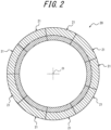
- the tread molding portion 20 is divided into a plurality of circumferentially aligned segments 21.
- Each of the segments 21 is arc-shaped when viewed from the top.
- Each of the segments 21 is assembled circumferentially to form the tread molding portion 20, which is a circular mold as a whole.
- the tread molding portion 20 consists of nine segments 21 that are identical to each other in circumferential length. Note, that the number of circumferential divisions of the tread molding portion 20 is preferably from 7 to 13, but is not limited to this and can be changed as appropriate.
- the plurality of segments 21 which constitute the tread molding portion 20 each have a holder 22 and a design surface-divided mold section 23.
- the holder 22 can be formed by cutting a block of metal, such as low-carbon steel, for example.
- the design surface-divided mold section 23 is the portion that constitutes the tread design surface 20a for molding the tread 2c of the tire 2. It is arc-shaped when viewed from the top, and its radially inner side constitutes a circumferentially divided portion of the tread design surface 20a.
- the design surface-divided mold section 23 is disposed radially inner side of the corresponding holder 22 and is fixed to the holder 22 using bolts or other fixing members not illustrated in the figure.
- the design surface-divided mold section 23 can be configured with a plurality of protrusions 24 protruding radially inner side along the radial direction from the tread design surface 20a.
- the plurality of protrusions 24 are for forming grooves or sipes, etc., which make up a tread pattern 2d as a pattern of design surface on the tread 2c of the tire 2 during vulcanizing and molding.
- the plurality of protrusions 24 can be of various shapes or sizes (lengths), such as those extending in the tire width direction or in the tire circumferential direction, corresponding to the tread pattern 2d.
- the design surface-divided mold section 23 is preferably formed by casting a metal material with high thermal conductivity, such as an aluminum alloy, for example.
- the design surface-divided mold section 23 can be configured by integrating the rib- or blade-shaped protrusions 24 made of steel into the design surface-divided mold section 23 at the time of casting the design surface-divided mold section 23.
- each segment 21 comprises a pivot shaft 5 that is provided at one end side (lower end side in the case illustrated in Figure 3 ), in the direction of the center axis of the tread molding portion 20, perpendicular to each of the direction of movement (radial direction) of the segments 21 and the center axis of the tread molding portion 20 at one end.
- this embodiment describes a case in which the pivot shaft 5 is provided at the lower end portion of the holder 22.
- the pivot shaft 5 may be provided in the design surface-divided mold section 23.
- each segment 21 an individual base member 6 corresponding to the segment 21 is disposed below each segment 21, an individual base member 6 corresponding to the segment 21 is disposed.
- the base member 6 supports the pivot shaft 5, thereby pivotally supporting the segment 21 about the pivot shaft 5.
- the segment 21 is pivotally movable with respect to the base member 6 about the pivot shaft 5.
- the tread molding portion 20 can be opened, after vulcanizing the tire 2 with the respective segments 21 in the defined position, by pivotally moving the respective segments 21 radially outward from the defined position about the pivot shaft 5 so that to release the tread 2c from the tread design surface 20a.
- the mold 1 for forming a tire comprises a guide rail 25 that extends along the radial direction of the segment 21, supported by the lower container 3 and the lower sidewall molding portion 11.
- the guide rail 25 supports the base member 6 so that the base member 6 is movable in the radial direction of the tread molding portion 20. This allows the base member 6 a radial movement about the enter axis of the tread molding portion 20 (center axis O, see Figures 1 and 2 ).
- a spring member for sliding 26 is disposed between the base member 6 and the lower sidewall molding portion 11, and that biases the base member 6 radially outward of the tread molding portion 20.
- Each of the segments 21 is urged radially outward by the corresponding spring member for sliding 26.
- an external force application mechanism 30 that applies an external force to the segment 21 in a direction to cause the segment 21 pivotally moving about the pivot shaft 5 so that the upper end side of the segment 21 moves radially outward, when the tread molding portion 20 is opened radially outward after vulcanizing and molding of the tire 2.
- the external force application mechanism 30 comprises a spring member for pivotal movement 31 that applies a spring force to the segment 21 as an external force.
- the external force application mechanism 30 is not limited to a configuration with the spring member for pivotal movement 31 that applies a spring force to the segment 21 as an external force, but can also be configured to apply an external force to the segment 21 by a drive source such as an air cylinder, for example.
- the external force application mechanism 30 comprises a shaft body 32 fixed in a vertical position extending vertically on the top surface of the base member 6.
- the shaft body32 is inserted into a hole 22a provided in the holder 22 constituting the segment 21, and a flange 33 at its upper end is disposed in the hole 22a.
- the spring member for pivotal movement 31 is a compression coil spring and is disposed in a compressed state between the flange 33 and the bottom wall of the hole 22a. This applies an external force to the segment 21 from the external force application mechanism 30 in a direction to cause the segment 21 pivotally moving about the pivot shaft 5 so that the upper end side of the segment 21 moves radially outward.
- an outer ring 7 is disposed on the radially outer side of each segment 21 so that to hold the segment 21 in a defined position against the external force applied by the external force application mechanism 30.
- the outer ring 7 is disposed on the radially outer side of the segment 21 and is movable between a holding position that holds the segment 21 in the defined position and a release position that allows the segment 21 to tilt radially outward of the tread molding portion 20.
- the outer ring 7 is fixed to the upper container 4 via the upper sidewall molding portion 12 and can move with the upper container 4 relative to the segment 21 supported by the lower container 3 or the base member 6 in the vertical direction.
- the defined position is the position where the tread design surface 20a provided on the design surface-divided mold section 23 of one segment 21 is in a continuous posture along the circumferential direction with respect to the tread design surface 20a provided on the design surface-divided mold section 23 of the other segments 21.
- the outer ring 7 comprises a first inclined surface 7a on its inner circumferential surface facing radially inward, which slopes upward to gradually decrease in outer diameter. Also, the outer ring 7 comprises a second inclined surface 7b on its outer circumferential surface facing radially outward, which slopes upward to gradually decrease in outer diameter.
- the second inclined surface 7b is a surface along the first inclined surface 7a.
- each segment 21 comprises a tapered surface 21a on its outer circumferential surface facing radially outward, that slopes upward to gradually decrease in outer diameter.
- the tapered surface 21a is provided on the outer circumference of the holder 22.
- the tapered surface 21a is an inclined surface roughly along the first inclined surface 7a.
- the first inclined surface 7a contacts the tapered surface 21a of the segment 21 to hold the segment 21 in the defined position.
- the outer ring 7 can move along the direction of the center axis with the upper container 4 to the release position, which is located on the upper side than the holding position, when the upper container 4 moves upward and the tread molding portion 20 is opened. Note, that the outer ring 7 can close the tread molding portion 20 by moving along the direction of the center axis of the segment from the release position to the holding position.
- a tilting mechanism is provided to adjust the tilting state of the segment 1 by pivotally moving the segment 21 radially outward or inward about the pivot shaft 5, when the tread molding portion 20 is opened radially outward after vulcanizing and molding the tire 2.
- the tilting mechanism tilts the segment 21 radially outward and applies an external force to the segment 21 to revert the tilt of the segment 21.
- the tilting mechanism is configured to revert the tilt of the segment 21 after the tread molding portion 20 is opened and before the tread molding portion 20 is completely separated from the tire tread.
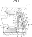
- the tilting mechanism in addition to the above-mentioned pivot shaft 5 (see Figure 3 ) and the base member 6, further includes: a first link 50 as a first tilting mechanism that pivotally moves the segment 21 about the pivot shaft 5, as a center of pivotal movement, to tilt the segment 21 when the tread molding portion is opened; and a second link 40 as a second tilting mechanism that pivotally moves the segment 21 about the pivot shaft 5, as a center of pivotal movement, to revert the tilt of the segment 21 after the tread molding portion is opened (after it has started to open).
- a first link 50 as a first tilting mechanism that pivotally moves the segment 21 about the pivot shaft 5, as a center of pivotal movement, to tilt the segment 21 when the tread molding portion is opened
- a second link 40 as a second tilting mechanism that pivotally moves the segment 21 about the pivot shaft 5, as a center of pivotal movement, to revert the tilt of the segment 21 after the tread molding portion is opened (after it has started to open).
- the first link 50 is a member with a shape similar to the shape of U, a capital letter of the alphabet, as illustrated in Figure 3 .
- the first link 50 in this embodiment is longer at one end than at the other end when viewed from the valley portion in the U-shape.
- the first link 50 is bridged from the segment 21 to the outer ring 7.
- the first link 50 is connected to one end portion of the segment 21 and is capable of engaging with the second inclined surface 7b.
- the first link 50 is connected to the segment 21 at one end thereof by being supported on a support axis 65 extending in the circumferential direction of the tread molding portion 20 at the upper end side of the segment 21 (holder 22, as an example, in this embodiment).
- the first link 50 is supported by a support axis 61 of the link support 60 extending from the top surface of the lower container 3 and is capable of engaging with the second inclined surface 7b.
- a long hole 51 is formed at one end of the first link 50.
- the first link 50 is connected to the segment 21 by the support axis 65 inserted through this long hole 51.
- the first link 50 is supported by the support axis 61 at the end portion of the segment 21 side in the U-shaped valley portion, and be pivotally movable about the support axis 61 as the pivot center.
- the first link 50 has its other end disposed radially outer side of the tread molding portion 20 than the second inclined surface 7b and is capable of engaging with the second inclined surface 7b.
- the first link 50 has a projection 52 facing the second inclined surface 7b on the tip side (upper end portion) at the other end.
- the first link 50 is towed by the second inclined surface 7b to tow the upper end portion of the segment 21 radially outward to tilt the segment 21.
- the pivotal movement of the segment 21 radially outward about the pivot shaft 5 moves the upper-end side of the segment 21 radially outward, thereby causing the segment 21 to be tilted. Note, that in the following description, the movement of the outer ring 7 from the defined position to the release position may simply be described as the raising of the outer ring 7, etc.
- the second link 40 is a member with a shape similar to the shape of U, a capital letter of the alphabet, as illustrated in Figure 3 .
- the second link 40 in this embodiment is shorter or approximately the same length at one end than at the other end when viewed from the valley portion in the U-shape.
- the second link 40 is bridged from the segment 21 to the outer ring 7.
- the second link 40 is connected to a different end of the segment 21 than the side to which the first link 50 is connected, and is capable of engaging with the second inclined surface 7b.
- the second link 40 is connected to the segment 21 by being supported on a support axis 64 extending in the circumferential direction of the tread molding portion 20 at the lower end side of the segment 21 (holder 22, as an example, in this embodiment), that is, below the position where the first link 50 is connected to the segment 21.
- the second link 40 is engaged to the support axis 61 of the link support 60 and the second inclined surface 7b.
- a long hole 41 is formed at one end of the second link 40.
- the second link 40 is engaged to the segment 21 by the support axis 64 inserted through this long hole 41.
- the second link 40 is supported by the support axis 61 at the end portion of the segment 21 side in the U-shaped valley portion, and is pivotally movable about the support axis 61 as the pivot center.
- the second link 40 has its other end disposed radially outer side of the tread molding portion 20 than the second inclined surface 7b and is capable of engaging with the second inclined surface 7b.
- the second link 40 has a projection 42 facing the second inclined surface 7b on the tip side (upper end portion) at the other end.
- the projection 42 is disposed above the projection 52 of the first link 50.
- the projection 42 is disposed farther radially outward from the second inclined surface 7b than the projection 52.
- the second link 40 is towed by the second inclined surface 7b as the outer ring 7 rises, thereby towing the tilted segment 21 radially outward to revert the tilt of the segment 21.
- the pivotal movement of the segment 21 radially inward about the pivot shaft 5 moves the lower-end side of the segment 21 radially outward, thereby getting up the segment 21.
- the first link 50 may be disposed circumferentially outer side of the tread molding portion 20 than the second link 40, as illustrated in Figure 5 , as an example. On the radially outer side from the second inclined surface 7b, the upper end of the first link 50 is positioned lower than the upper end of the second link 40.
- the mold 1 for forming a tire comprises a bladder 8 that is disposed inside a raw tire and expands when pressurized steam is supplied.
- the mold 1 for forming a tire comprises a heater (not illustrated) for heating the sidewall molding portion 10 and the tread molding portion 20.
- the installation position of the heater can be set as appropriate.
- a tire production method for producing the tire 2 of a predetermined shape by vulcanizing and molding a raw tire using the tire mold 1 for forming a tire having the above configuration i.e., a tire production method, which is an embodiment of the present disclosure will be described.
- a raw tire is placed inside the mold 1 for forming a tire with the sidewall molding portion 10 and the tread molding portion 20 in the open position, and then the sidewall molding portion 10 and tread molding portion 20 are closed, as illustrated in Figures 1 and 3 .
- the outer ring 7 contacts the segment 21 with its first inclined surface 7a, which biases the segment 21 radially inward and moves the segment 21 inward in the radial direction.
- the projection 52 of the first link 50 and the projection 42 of the second link 40 are separated from the second inclined surface 7b (see Figure 3 ).
- the projection 42 is positioned further away from the second inclined surface 7b than the projection 52. In other words, the distance between the projection 42 and the second inclined surface 7b is longer than the distance between the projection 52 and the second inclined surface 7b.
- pressurized steam is supplied to the bladder 8 disposed inside the raw tire to expand the bladder 8, which presses both sidewalls of the raw tire against the lower sidewall design surface 11a or the upper sidewall design surface 12a of the sidewall molding portion 10, respectively, and also presses the tread against the tread design surface 20a of the tread molding portion 2.
- the sidewall molding portion 10 and the tread molding portion 20 are heated by a heater, and the synthetic rubber that constitutes the raw tire is vulcanized by the heat to form a tire 2 of a predetermined shape.
- the sidewall molding portion 10 and the tread molding portion 20 are opened and the molded tire 2 is removed.
- a first process in which the segment 21 is tilted radially outward of the tread molding portion 20 is performed.
- the projection 52 of the first link 50 contacts the second inclined surface 7b as the outer ring 7 rises, and the first link 50 is engaged to the second inclined surface 7b.
- the projection 52 is towed radially outward while sliding downward and radially outward relative to the second inclined surface 7b. This causes the first link 50 to tow the segment 21 and tilt the segment 21 radially outward.
- the tread design surface 20a of the design surface-divided mold section 23 is inclined with respect to the tread 2c of the tire 2.
- one end in the width direction of tire 2 (upper end side in Figure 6 ) of the tread design surface 20a in the design surface-divided mold section 23 is gradually detached from the tread 2c of the tire 2 before the other end (lower end side in Figure 6 ).
- This allows outside air to be gradually introduced between the tread 2c and the tread design surface 20a from that one end side, thereby reducing the release resistance from the tread design surface 20a of the tread 2c of the tire 2.
- the projection 42 of the second link 40 may remain separated from the second inclined surface 7b.
- a second process (see the operation from Figure 6 to Figure 7 ) is performed to revert the tilt of the segment 21.
- the second process should be performed when a portion of the tread design surface 20a in the design surface-divided mold section 23 has been detached, but the protrusions 24 are not fully detached from the tread pattern 2d, i.e., before the tread design surface 20a in the segment 21 is completely separated from the tread 2c of tire 2. In this process, as illustrated in Fig.
- the projection 52 slips off from the second inclined surface 7b as the outer ring 7 rises, the first link 50 is released from its engagement to the second inclined surface 7b, and the projection 42 of the second link 40 contacts the second inclined surface 7b, and the second link 40 is engaged to the second inclined surface 7b.
- the second link 40 can tow the lower end of the segment 21 radially outward.
- the tread design surface 20a of the design surface-divided mold section 23 is along (parallel to in this embodiment) the tread 2c of the tire 2.
- the tread design surface 20a of the design surface-divided mold section 23 is along the tread 2c of the tire 2, for example, the protrusions 24 are aligned with the grooves, etc. of the tread pattern 2d, i.e., any of the protrusions 24 can be pulled straight out of the tread pattern 2d.
- the tire release resistance from the tread design surface 20a that is brought on the tread 2c of the tire 2 can be reduced.
- the tread molding portion 20 opens as the outer ring 7 is further raised, and the segment 21 moves radially outward (see the movement from Figure 7 to Figure 8 ), thereby completing the detachment of the tread design surface 20a in the design surface-divided mold section 23 (see Figure 8 ).
- the projection 42 also slides off from the second inclined surface 7b, the engagement of the second link 40 to the second inclined surface 7b is also released, and the tread molding portion 20 then fully opens as described below (see Figure 9 ).
- the mold 1 for forming a tire in this embodiment has a guide rail 25 that supports the base member 6 freely movable in the radial direction of the tread molding portion 20 and a spring member for sliding 26 that biases the base member 6 radially outward of the tread molding portion 20, as illustrated in Figure 4 .
- the segment 21 spontaneously pivotally moves radially outward from the defined position about the pivot shaft 5 by the external force applied by the external force application mechanism 30, and at the same time, the segment 21 is energized by the spring member for sliding 26 and moves radially outward along the guide rail 25 together with the base member 6.
- the tread molding portion 20 is completely opened.
- the segment 21 is tilted in the radial direction (radially outward in the example of this embodiment) by the tilting mechanism (see Figure 6 ), so that at the beginning of the release of the tire 2 from the mold, the force required to release the tread 2c of the tire 2 from the tread design surface 20a can be reduced.
- the driving force applied to the segment 21 can be reduced, which reduces the energy required for production and thus lowers production costs.
- the mold release resistance of the tread 2c of the tire 2 from the tread design surface 20a can be reduced, residual strain (permanent deformation) in the tire 2 after releasing from the mold can be prevented and the initial performance of the tire 2 can be improved.
- the segment 21 is got up by the tilting mechanism to bring the tread design surface 20a in the design surface-divided mold section 23 to being along the tread 2c of the tire 2 (see Figure 7 ), so that to reduce the undercut resistance brought by the protrusions 24 against the tread 2c of the tire 2, thereby reducing the driving force required to drive the segment 21 during releasing the tire 2 from the mold. Furthermore, when releasing the tire 2 from the tread molding portion 20, the excessive undercut resistance can be prevented, so that to control the defects such as permanent deformation of the tread 2c of the tire 2 after molding or the damage to the protrusions 24, etc.
- the mold 1 for forming a tire of this embodiment is configured, as described above, such that when the outer ring 7 is moved (raised) to the release position, as illustrated in figure 9 , the segment 21 spontaneously pivotally moves radially outward from the defined position about the pivot shaft 5 by the external force applied by the external force application mechanism 30, and at the same time, the segment 21 is energized by the spring member for sliding 26 and moves radially outward along the guide rail 25 together with the base member 6.
- segment 21 This allows the segment 21 to reduce the undercut resistance brought by the protrusions 24 against the tread 2c of the tire 2 when the segment 21 pivotally moves about the pivot shaft 5, for example, when the height of the protrusion 24 on the tread design surface 20a is high, such as when molding large tires used for construction vehicles, etc.
- segment 21 can be moved to a position where the protrusions 24 are not in the way when releasing the tire 2 so that the tire 2 can be released more easily.
- the mold 1 for forming a tire of this embodiment is configured with the outer ring 7 which is disposed on the radially outer side of the segment 21 and is movable between the holding position that holds the segment 21 in a defined position and the release position that allows the segment 21 to move pivotally about the pivot shaft 5, the opening and closing mechanism of the segment 21 can be simplified to further reduce the production cost of the tire 2.
- the mold 1 for forming a tire of this embodiment can be configured so that when the tread molding portion 20 is opened after vulcanizing and molding the tire 2, one segment (first segment) 21 of the plurality of segments 21 pivotally moves (tilts) radially outward about the pivot shaft 5 (first pivot shaft) as a center, and then the other segment (second segment) 21 pivotally moves (tilts) radially outwards about the pivot shaft 5 (second pivot shaft) as a center.
- a plurality of segments 21 can be configured to pivotally move in sequence, with a time difference between each segment 21. This reduces the maximum driving force required to drive the segments.
- the segments 21 can be configured to pivotally move radially outward about the pivot shaft 5 as a center, in turn along the circumferential direction, so that after one segment 21 pivotally moves radially outward about the pivot shaft 5 as a center, the segment 21 adjacent to that segment 21 pivotally moves radially outward about the pivot shaft 5 as a center, and then the segment 21 adjacent to that segment 21 pivotally moves radially outward about the pivot shaft 5 as a center, and so on.
- This configuration allows the tread 2c of the tire 2 to be released from the tread design surface 20a with a smaller driving force by causing the tread 2c of the tire 2 to be released in circumferential order from a portion of the tread design surface 20c in the initial stage of releasing the tire 2 from the mold.
- the above embodiment describes a case in which the projection 42 is disposed above the projection 52 of the first link 50, and the projection 42 is disposed further away from the second inclined surface 7b than the projection 52.
- the projection 42 can be disposed below the projection 52 of the first link 50 and the projection 52 can be disposed further away from the second inclined surface portion 7b than the projection 42.
- the first link 50 can tow the upper end of the segment 21 radially outward.
- the first embodiment describes a case in which the mold 1 for forming a tire has a first tilting mechanism and a second tilting mechanism as a tilting mechanism, and the first tilting mechanism being a first link 50 and the second tilting mechanism being a second link 40.
- the second embodiment includes, instead of the first link 50 and the second link 40, an engagement groove 28 formed in a tapered surface 21a of the segment 21 and a rail 70 formed in the first inclined surface 7a of the outer ring 7 as a tilting mechanism, as illustrated in Figure 11 .
- the following description will focus on the parts that differ from the first embodiment, and redundant explanations will be omitted where appropriate.
- the engagement groove 28 is formed as a groove extending along the vertical and radial directions in the tapered surface 21a.
- the rail 70 is formed as a rail-like member extending along the vertical and radial directions in the first inclined surface 7a.
- the engagement groove 28 and the rail 70 are of any shape as long as: the rail 70 can be engaged by, for example, fitting into the engagement groove 28; and the rail 70 can be pulled out by towing the segment 21 radially outward through the engagement groove 28 in an engaged state; and the combination is capable of sliding along the extending direction of the engagement groove 28 in the engaged state.
- the engagement groove 28 has a shape in which the bottom of the groove expands circumferentially back and forth, as illustrated in Figures 12 and 13 , as an example.
- the engagement groove 28 is T-shaped, a capital letter T of the alphabet, in a cross-section when viewed along the extending direction of the engagement groove 28, for example.
- the radially inner surface is indicated as an inner surface 28a
- the radially outer surface is indicated as an outer surface 28b.
- the rail 70 in this embodiment, extends from the first inclined surface 7a and further has a tip portion protruding back and forth in the circumferential direction.
- the rail 70 is T-shaped, a capital letter T of the alphabet, in a cross-section when viewed along the extending direction of the rail 70, for example.
- the rail 70 when fitted into the engagement groove 28, has a horizontal bar portion at the tip of T-shape that engages with the engagement groove 28.
- the radial outer surface of the rail 70 is generally flat 71 (see Figure 12 ), and the upper end of the rail 70 has a convex part 72 that projects radially outward (see Figure 13 ).
- the convex part 72 is formed at a predetermined range along the extending direction of the rail 70 at the upper end of the rail 70.
- the portion of the rail 70 below the convex part 72 is a flat part 71.
- the outer ring 7 has its first inclined surface 7a in contact with the segment 21.
- the outer ring 7 has its first inclined surface 7a in contact with the segment 21, which biases the segment 21 radially inward and moves the segment 21 radially inward.
- the rail 70 is in contact with or separated from the inner surface 28a of the engagement groove 28 and separated from the outer surface 28b (see Figures 12 and 13 ).
- a first process is performed to tilt the segment 21 radially outward of the tread molding portion 20.
- the raising of the outer ring 7 causes the convex part 72 to contact the outer side 28b, and the convex part 72 biases the upper end of the segment 21 radially outward through the outer side 28b, thereby causing the segment 21 to pivotally move and tilt.
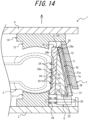
- This causes the tread 2c of the tire 2 to be gradually released, with one-end side of the tread design surface 20a in the width direction of the tire 2 (the upper-end side in Figure 14 ) released before the other-end side (the lower-end side in Figure 14 ).
- the convex part 72 is in contact with the outer surface 28b, the flat part 71 is separated from the outer surface 28b, or only the lower edge portion of the flat part 71 is in contact with the outer surface 28b.
- a second process is performed to revert the tilt of the segment 21 (see the operation from Figure 14 to Figure 15 ).
- the second process should be performed before the tread design surface 20a in the segment 21 has completely been separated from the tread 2c of the tire 2.
- the raising of the outer ring 7 causes the convex part 72 to exit the engagement groove 28, thereby leaving the flat part 71 in broad contact with the outer surface 28b of the engagement groove 28.
- the tread molding portion 20 opens as the outer ring 7 is further raised, and the segment 21 moves radially outward (see the movement from Figure 15 to Figure 16 ) to complete the detaching of the tread design surface 20a (see Fig. 16 ).
- the upper end of the segment 21 may slope radially outward when only the lower end of the flat part 71 is in contact with the upper end in the outer surface 28b of the engagement groove 28.
- the segment 21 spontaneously pivotally moves radially outward about the pivot shaft 5 from the defined position by the external force applied by the external force application mechanism 30.
- the segment 21 is energized by the spring member for sliding 26 and moves radially outward along the guide rail 25 together with the base member 6.
- the tread molding portion 20 is completely opened.
- the tilting mechanism is composed of the engagement groove 28 and the rail 70, as in this embodiment, there is no need to use movable parts, e.g. the first link 50 and the second link 40 in the first embodiment, as the tilting mechanism and the structure is simplified, thereby enabling cost reduction.
Landscapes
- Engineering & Computer Science (AREA)
- Mechanical Engineering (AREA)
- Physics & Mathematics (AREA)
- Health & Medical Sciences (AREA)
- Oral & Maxillofacial Surgery (AREA)
- Thermal Sciences (AREA)
- Moulds For Moulding Plastics Or The Like (AREA)
- Heating, Cooling, Or Curing Plastics Or The Like In General (AREA)
- Tyre Moulding (AREA)
Abstract
Description
- The present disclosure relates to a mold for forming a tire and a tire production method.
- As a conventional mold for forming a tire used in producing a tire by vulcanizing and molding an unvulcanized raw tire, it is known that a circular tread molding portion (tread mold) for forming a tire tread is divided into a plurality of circumferentially aligned segments and it opens and closes due to radial movement of each segment (see, for example,
Patent Literature 1 to 3). -
- PTL 1:
JP 2000/326332 A1 - PTL 2:
JP 2000/334740 A1 - PTL 3:
JP 2009/149079 A1 - However, in the above conventional mold for forming a tire or tire production method, when the tire is released from the tread molding portion after vulcanizing and molding, each segment moves radially outward while maintaining its posture with respect to the tire tread, so that the entire tread design surface, which is for molding the tread, of each segment is detached from the tread at the same time. Therefore, a large driving force is required to drive the segments until the segments are detached from the tire.
- For example, in the early stages of tire releasing from a mold, the tread design surface of the segment must be detached from the tread, and protrusions of the segment corresponding to the design surface pattern of the tire must be pulled out therefrom. Therefore, when the tread design surface of the segment was detached from the tread, a large driving force was required to release the adhesion between the tread design surface and the tread. In addition, during the period until the segment is detached from the tire, due to the undercut resistance which is generated when the protrusions of the segment corresponding to the design surface pattern of the tire is pulled out therefrom, large driving force was required to drive the segment.
- This disclosure has been made in view of these circumstances, and its purpose is to provide a mold for forming a tire and a tire production method that can reduce the driving force required to drive the segment in the initial stage of releasing a tire from the mold.
- The mold for forming a tire in accordance with the present disclosure to achieve the above-mentioned purpose comprises:
- a circular tread molding portion divided into a plurality of circumferentially aligned segments; and
- a tilting mechanism that tilts the segments radially outward when the tread molding portion is opened radially outward, and
- the tilting mechanism reverts the tilt of the segments after the tread molding portion is opened.
- The tire production method in accordance with the present disclosure to achieve the above-mentioned purpose is,
- a tire production method using a mold for forming a tire which comprises a circular tread molding portion divided into a plurality of circumferentially aligned segments, including:
- a first process of tilting the segment radially outward of the tread molding portion when the tread molding portion is opened after vulcanizing and molding an unvulcanized raw tire; and
- a second process of reverting the tilt of the segment after the tread molding portion is opened.
- This disclosure can provide a mold for forming a tire and a tire production method that can reduce the driving force required to drive the segment in the initial stage of releasing a tire from a mold.
- In the accompanying drawings:
-
FIG. 1 is a cross-sectional view of a mold for forming a tire according to one embodiment of this disclosure when viewed from the front; -
FIG. 2 is a cross-sectional view of a tread molding portion when viewed from the top; -
FIG. 3 is an enlarged cross-sectional view when viewed from the front, illustrating a detailed structure of key parts of the mold for forming a tire in the first embodiment; -
FIG. 4 is an enlarged cross-sectional view when viewed from the front, illustrating a detailed structure of a lower part of one segment in the first embodiment; -
FIG. 5 illustrates one segment in the first embodiment viewed from radially outer side of the tread molding portion; -
FIG. 6 is a cross-sectional view when viewed from the front, illustrating the state of key parts of the mold for forming a tire in the first embodiment at the initial stage of releasing a tire from the mold; -
FIG. 7 is a cross-sectional view when viewed from the front, illustrating the state of the key parts of the mold for forming a tire when the tire releasing is further advanced from the state illustrated inFIG. 6 ; -
FIG. 8 is a cross-sectional view when viewed from the front, illustrating the state of the key parts of the mold for forming a tire when the tire releasing has been completed; -
FIG. 9 is a cross-sectional view when viewed from the front, illustrating the state of the key parts of the mold for forming a tire when the tread molding portion is fully open; -
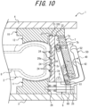
FIG. 10 is an enlarged cross-sectional view when viewed from the front, illustrating a detailed structure of key parts of the mold for forming a tire in a variation of the first embodiment; -
FIG. 11 is an enlarged cross-sectional view when viewed from the front, illustrating a detailed structure of key parts of the mold for forming a tire in the second embodiment; -
FIG. 12 is a cross-sectional view along A-A inFig. 11 ; -
FIG. 13 is a cross-sectional view along B-B inFig. 11 ; -
FIG. 14 is a cross-sectional view when viewed from the front, illustrating the state of key parts of the mold for forming a tire in the second embodiment at the initial stage of releasing a tire from the mold; -
FIG. 15 is a cross-sectional view when viewed from the front, illustrating the state of the key parts of the mold for forming a tire when the tire releasing is further advanced from the state illustrated inFIG. 14 ; and -
FIG. 16 is a cross-sectional view when viewed from the front, illustrating the state of the key parts of the mold for forming a tire when the tire releasing has been completed. - The following is a detailed illustration of a mold for forming a tire and a tire production method, with reference to the drawings. Note that the same reference numerals are given to common members and parts in each figure.
- A
mold 1 for forming a tire in accordance with one embodiment of the present disclosure, illustrated inFigure 1 , is used to produce atire 2 by molding a raw tire formed mainly of unvulcanized (pre-vulcanized) synthetic rubber into a predetermined shape while vulcanizing it. - The
tire 2 is a hollow tire made mainly of synthetic rubber, having a pair ofsidewalls tread 2c, and formed into a shape with an interior space filled with air, nitrogen or other gas. - The
mold 1 for forming a tire has asidewall molding portion 10 and atread molding portion 20. - The
sidewall molding portion 10 can, for example, consist of a circular lowersidewall molding portion 11 fixed to the upper surface of alower container 3 and a circular uppersidewall molding portion 12 fixed to the lower surface of aupper container 4. - The
sidewall molding portion 10 can position (store) thecircular tire 2 or a raw tire between the lowersidewall molding portion 11 and the uppersidewall molding portion 12 in an orientation where the center axis of the tire is coaxial with the center axis O of thesidewall molding portion 10. - The lower
sidewall molding portion 11 comprises a circular, upward-facing lowersidewall design surface 11a, centered on the central axis O. The lowersidewall design surface 11a can be used to mold the outer surface of onesidewall 2a of thetire 2 or the raw tire (the side facing downward inFigure 1 ). - Similarly, the upper
sidewall molding portion 12 comprises a circular, downward-facing uppersidewall design surface 12a, centered on the central axis O. The uppersidewall design surface 12a can be used to mold the outer surface of theother sidewall 2b of thetire 2 or the raw tire (the side facing upward inFigure 1 ). - The
sidewall molding portion 10 is opened by moving theupper container 4 relative to thelower container 3 upward from the position illustrated inFigure 1 (in the direction where both are separated along the central axis of the tire 2), and thetire 2 is released from thesidewall molding portion 10. Meanwhile, as theupper container 4 moves downward to its original position illustrated inFigure 1 , thesidewall molding portion 10 is closed from its open state to a state where thetire 2 or the raw tire can be molded. - Note, that the configuration of the
sidewall molding portion 10 can be changed as needed. For example, thesidewall molding portion 10 is opened by moving thelower container 3 downward relative to theupper container 4. - The
tread molding portion 20 is circular and coaxial with thesidewall molding portion 10. Thetread molding portion 20 is disposed radially outward of the lowersidewall molding portion 11 and theupper sidewall portion 12 adjacent to them. The inner surface of thetread molding portion 20 facing radially inward is atread design surface 20a, which molds the outer surface of thetread 2c of thetire 2. - As illustrated in
Figure 2 , thetread molding portion 20 is divided into a plurality of circumferentially alignedsegments 21. Each of thesegments 21 is arc-shaped when viewed from the top. Each of thesegments 21 is assembled circumferentially to form thetread molding portion 20, which is a circular mold as a whole. In this embodiment, thetread molding portion 20 consists of ninesegments 21 that are identical to each other in circumferential length. Note, that the number of circumferential divisions of thetread molding portion 20 is preferably from 7 to 13, but is not limited to this and can be changed as appropriate. - As illustrated in
Figure 3 , in this embodiment, the plurality ofsegments 21 which constitute thetread molding portion 20 each have aholder 22 and a design surface-dividedmold section 23. - The
holder 22 can be formed by cutting a block of metal, such as low-carbon steel, for example. - The design surface-divided
mold section 23 is the portion that constitutes thetread design surface 20a for molding thetread 2c of thetire 2. It is arc-shaped when viewed from the top, and its radially inner side constitutes a circumferentially divided portion of thetread design surface 20a. The design surface-dividedmold section 23 is disposed radially inner side of the correspondingholder 22 and is fixed to theholder 22 using bolts or other fixing members not illustrated in the figure. - The design surface-divided
mold section 23 can be configured with a plurality ofprotrusions 24 protruding radially inner side along the radial direction from thetread design surface 20a. The plurality ofprotrusions 24 are for forming grooves or sipes, etc., which make up atread pattern 2d as a pattern of design surface on thetread 2c of thetire 2 during vulcanizing and molding. The plurality ofprotrusions 24 can be of various shapes or sizes (lengths), such as those extending in the tire width direction or in the tire circumferential direction, corresponding to thetread pattern 2d. - The design surface-divided
mold section 23 is preferably formed by casting a metal material with high thermal conductivity, such as an aluminum alloy, for example. In this case, for example, the design surface-dividedmold section 23 can be configured by integrating the rib- or blade-shapedprotrusions 24 made of steel into the design surface-dividedmold section 23 at the time of casting the design surface-dividedmold section 23. - As illustrated in
Figure 3 , eachsegment 21 comprises apivot shaft 5 that is provided at one end side (lower end side in the case illustrated inFigure 3 ), in the direction of the center axis of thetread molding portion 20, perpendicular to each of the direction of movement (radial direction) of thesegments 21 and the center axis of thetread molding portion 20 at one end. As an example, this embodiment describes a case in which thepivot shaft 5 is provided at the lower end portion of theholder 22. Thepivot shaft 5 may be provided in the design surface-dividedmold section 23. - Below each
segment 21, anindividual base member 6 corresponding to thesegment 21 is disposed. Thebase member 6 supports thepivot shaft 5, thereby pivotally supporting thesegment 21 about thepivot shaft 5. In other words, thesegment 21 is pivotally movable with respect to thebase member 6 about thepivot shaft 5. - The
tread molding portion 20 can be opened, after vulcanizing thetire 2 with therespective segments 21 in the defined position, by pivotally moving therespective segments 21 radially outward from the defined position about thepivot shaft 5 so that to release thetread 2c from thetread design surface 20a. - In this embodiment, as illustrated in
Figure 4 , themold 1 for forming a tire comprises aguide rail 25 that extends along the radial direction of thesegment 21, supported by thelower container 3 and the lowersidewall molding portion 11. Theguide rail 25 supports thebase member 6 so that thebase member 6 is movable in the radial direction of thetread molding portion 20. This allows the base member 6 a radial movement about the enter axis of the tread molding portion 20 (center axis O, seeFigures 1 and2 ). - In addition, as illustrated in
Figure 4 , a spring member for sliding 26 is disposed between thebase member 6 and the lowersidewall molding portion 11, and that biases thebase member 6 radially outward of thetread molding portion 20. Each of thesegments 21 is urged radially outward by the corresponding spring member for sliding 26. When thebase member 6 moves in the radial direction, thesegment 21 supported thereby also moves in the radial direction together with thebase member 6. - Between each
segment 21 and thebase member 6 corresponding to thesegment 21, an externalforce application mechanism 30 is provided, that applies an external force to thesegment 21 in a direction to cause thesegment 21 pivotally moving about thepivot shaft 5 so that the upper end side of thesegment 21 moves radially outward, when thetread molding portion 20 is opened radially outward after vulcanizing and molding of thetire 2. - In this embodiment, the external
force application mechanism 30 comprises a spring member forpivotal movement 31 that applies a spring force to thesegment 21 as an external force. Note, that the externalforce application mechanism 30 is not limited to a configuration with the spring member forpivotal movement 31 that applies a spring force to thesegment 21 as an external force, but can also be configured to apply an external force to thesegment 21 by a drive source such as an air cylinder, for example. - More specifically, as illustrated in
Figure 4 , the externalforce application mechanism 30 comprises ashaft body 32 fixed in a vertical position extending vertically on the top surface of thebase member 6. The shaft body32 is inserted into ahole 22a provided in theholder 22 constituting thesegment 21, and aflange 33 at its upper end is disposed in thehole 22a. The spring member forpivotal movement 31 is a compression coil spring and is disposed in a compressed state between theflange 33 and the bottom wall of thehole 22a. This applies an external force to thesegment 21 from the externalforce application mechanism 30 in a direction to cause thesegment 21 pivotally moving about thepivot shaft 5 so that the upper end side of thesegment 21 moves radially outward. - As illustrated in
Figures 1 ,3 , and4 , anouter ring 7 is disposed on the radially outer side of eachsegment 21 so that to hold thesegment 21 in a defined position against the external force applied by the externalforce application mechanism 30. - The
outer ring 7 is disposed on the radially outer side of thesegment 21 and is movable between a holding position that holds thesegment 21 in the defined position and a release position that allows thesegment 21 to tilt radially outward of thetread molding portion 20. - The
outer ring 7 is fixed to theupper container 4 via the uppersidewall molding portion 12 and can move with theupper container 4 relative to thesegment 21 supported by thelower container 3 or thebase member 6 in the vertical direction. Note, that the defined position is the position where thetread design surface 20a provided on the design surface-dividedmold section 23 of onesegment 21 is in a continuous posture along the circumferential direction with respect to thetread design surface 20a provided on the design surface-dividedmold section 23 of theother segments 21. - The
outer ring 7 comprises a firstinclined surface 7a on its inner circumferential surface facing radially inward, which slopes upward to gradually decrease in outer diameter. Also, theouter ring 7 comprises a secondinclined surface 7b on its outer circumferential surface facing radially outward, which slopes upward to gradually decrease in outer diameter. The secondinclined surface 7b is a surface along the firstinclined surface 7a. - On the other hand, each
segment 21 comprises atapered surface 21a on its outer circumferential surface facing radially outward, that slopes upward to gradually decrease in outer diameter. In this embodiment, thetapered surface 21a is provided on the outer circumference of theholder 22. Thetapered surface 21a is an inclined surface roughly along the firstinclined surface 7a. - When the
outer ring 7 is in the holding position illustrated inFigures 1 and3 , the firstinclined surface 7a contacts the taperedsurface 21a of thesegment 21 to hold thesegment 21 in the defined position. Theouter ring 7 can move along the direction of the center axis with theupper container 4 to the release position, which is located on the upper side than the holding position, when theupper container 4 moves upward and thetread molding portion 20 is opened. Note, that theouter ring 7 can close thetread molding portion 20 by moving along the direction of the center axis of the segment from the release position to the holding position. - Between each
segment 21 and thebase member 6 and theouter ring 7 corresponding to thesegment 21, a tilting mechanism is provided to adjust the tilting state of thesegment 1 by pivotally moving thesegment 21 radially outward or inward about thepivot shaft 5, when thetread molding portion 20 is opened radially outward after vulcanizing and molding thetire 2. The tilting mechanism tilts thesegment 21 radially outward and applies an external force to thesegment 21 to revert the tilt of thesegment 21. - The tilting mechanism is configured to revert the tilt of the
segment 21 after thetread molding portion 20 is opened and before thetread molding portion 20 is completely separated from the tire tread. - As illustrated in
Figures 3 and5 , the tilting mechanism, in addition to the above-mentioned pivot shaft 5 (seeFigure 3 ) and thebase member 6, further includes: afirst link 50 as a first tilting mechanism that pivotally moves thesegment 21 about thepivot shaft 5, as a center of pivotal movement, to tilt thesegment 21 when the tread molding portion is opened; and asecond link 40 as a second tilting mechanism that pivotally moves thesegment 21 about thepivot shaft 5, as a center of pivotal movement, to revert the tilt of thesegment 21 after the tread molding portion is opened (after it has started to open). - The
first link 50 is a member with a shape similar to the shape of U, a capital letter of the alphabet, as illustrated inFigure 3 . Thefirst link 50 in this embodiment is longer at one end than at the other end when viewed from the valley portion in the U-shape. Thefirst link 50 is bridged from thesegment 21 to theouter ring 7. Thefirst link 50 is connected to one end portion of thesegment 21 and is capable of engaging with the secondinclined surface 7b. In this embodiment, thefirst link 50 is connected to thesegment 21 at one end thereof by being supported on asupport axis 65 extending in the circumferential direction of thetread molding portion 20 at the upper end side of the segment 21 (holder 22, as an example, in this embodiment). In addition, thefirst link 50 is supported by asupport axis 61 of thelink support 60 extending from the top surface of thelower container 3 and is capable of engaging with the secondinclined surface 7b. - A
long hole 51 is formed at one end of thefirst link 50. Thefirst link 50 is connected to thesegment 21 by thesupport axis 65 inserted through thislong hole 51. In addition, thefirst link 50 is supported by thesupport axis 61 at the end portion of thesegment 21 side in the U-shaped valley portion, and be pivotally movable about thesupport axis 61 as the pivot center. Thefirst link 50 has its other end disposed radially outer side of thetread molding portion 20 than the secondinclined surface 7b and is capable of engaging with the secondinclined surface 7b. In this embodiment, thefirst link 50 has aprojection 52 facing the secondinclined surface 7b on the tip side (upper end portion) at the other end. - As the
outer ring 7 moves from the defined position to the release position, thefirst link 50 is towed by the secondinclined surface 7b to tow the upper end portion of thesegment 21 radially outward to tilt thesegment 21. In this embodiment, the pivotal movement of thesegment 21 radially outward about thepivot shaft 5 moves the upper-end side of thesegment 21 radially outward, thereby causing thesegment 21 to be tilted. Note, that in the following description, the movement of theouter ring 7 from the defined position to the release position may simply be described as the raising of theouter ring 7, etc. - The
second link 40 is a member with a shape similar to the shape of U, a capital letter of the alphabet, as illustrated inFigure 3 . Thesecond link 40 in this embodiment is shorter or approximately the same length at one end than at the other end when viewed from the valley portion in the U-shape. Thesecond link 40 is bridged from thesegment 21 to theouter ring 7. Thesecond link 40 is connected to a different end of thesegment 21 than the side to which thefirst link 50 is connected, and is capable of engaging with the secondinclined surface 7b. In this embodiment, thesecond link 40 is connected to thesegment 21 by being supported on asupport axis 64 extending in the circumferential direction of thetread molding portion 20 at the lower end side of the segment 21 (holder 22, as an example, in this embodiment), that is, below the position where thefirst link 50 is connected to thesegment 21. In addition, thesecond link 40 is engaged to thesupport axis 61 of thelink support 60 and the secondinclined surface 7b. - A
long hole 41 is formed at one end of thesecond link 40. Thesecond link 40 is engaged to thesegment 21 by thesupport axis 64 inserted through thislong hole 41. In addition, thesecond link 40 is supported by thesupport axis 61 at the end portion of thesegment 21 side in the U-shaped valley portion, and is pivotally movable about thesupport axis 61 as the pivot center. Thesecond link 40 has its other end disposed radially outer side of thetread molding portion 20 than the secondinclined surface 7b and is capable of engaging with the secondinclined surface 7b. In this embodiment, thesecond link 40 has aprojection 42 facing the secondinclined surface 7b on the tip side (upper end portion) at the other end. Theprojection 42 is disposed above theprojection 52 of thefirst link 50. Theprojection 42 is disposed farther radially outward from the secondinclined surface 7b than theprojection 52. - The
second link 40 is towed by the secondinclined surface 7b as theouter ring 7 rises, thereby towing the tiltedsegment 21 radially outward to revert the tilt of thesegment 21. In this embodiment, the pivotal movement of thesegment 21 radially inward about thepivot shaft 5 moves the lower-end side of thesegment 21 radially outward, thereby getting up thesegment 21. - The
first link 50 may be disposed circumferentially outer side of thetread molding portion 20 than thesecond link 40, as illustrated inFigure 5 , as an example. On the radially outer side from the secondinclined surface 7b, the upper end of thefirst link 50 is positioned lower than the upper end of thesecond link 40. - The
mold 1 for forming a tire comprises abladder 8 that is disposed inside a raw tire and expands when pressurized steam is supplied. In addition, themold 1 for forming a tire comprises a heater (not illustrated) for heating thesidewall molding portion 10 and thetread molding portion 20. The installation position of the heater can be set as appropriate. - Next, a tire production method for producing the
tire 2 of a predetermined shape by vulcanizing and molding a raw tire using thetire mold 1 for forming a tire having the above configuration, i.e., a tire production method, which is an embodiment of the present disclosure will be described. - First, a raw tire is placed inside the
mold 1 for forming a tire with thesidewall molding portion 10 and thetread molding portion 20 in the open position, and then thesidewall molding portion 10 and treadmolding portion 20 are closed, as illustrated inFigures 1 and3 . - When closing the
tread molding portion 20, theouter ring 7 contacts thesegment 21 with its firstinclined surface 7a, which biases thesegment 21 radially inward and moves thesegment 21 inward in the radial direction. When thetread molding portion 20 is closed, theprojection 52 of thefirst link 50 and theprojection 42 of thesecond link 40 are separated from the secondinclined surface 7b (seeFigure 3 ). Theprojection 42 is positioned further away from the secondinclined surface 7b than theprojection 52. In other words, the distance between theprojection 42 and the secondinclined surface 7b is longer than the distance between theprojection 52 and the secondinclined surface 7b. - Next, pressurized steam is supplied to the
bladder 8 disposed inside the raw tire to expand thebladder 8, which presses both sidewalls of the raw tire against the lowersidewall design surface 11a or the uppersidewall design surface 12a of thesidewall molding portion 10, respectively, and also presses the tread against thetread design surface 20a of thetread molding portion 2. In this state, thesidewall molding portion 10 and thetread molding portion 20 are heated by a heater, and the synthetic rubber that constitutes the raw tire is vulcanized by the heat to form atire 2 of a predetermined shape. - After the molding of the
tire 2 is completed, thesidewall molding portion 10 and thetread molding portion 20 are opened and the moldedtire 2 is removed. - Here, after vulcanizing and molding the
tire 2, as theouter ring 7 moves upward (rises) from the holding position to the release position with respect to eachsegment 21 and thetread molding portion 20 is started opened, as illustrated inFigure 6 , a first process in which thesegment 21 is tilted radially outward of thetread molding portion 20 is performed. In this process, theprojection 52 of thefirst link 50 contacts the secondinclined surface 7b as theouter ring 7 rises, and thefirst link 50 is engaged to the secondinclined surface 7b. When theouter ring 7 rises further after theprojection 52 contacts the secondinclined surface 7b, with theprojection 52 is in contact with the secondinclined surface 7b, theprojection 52 is towed radially outward while sliding downward and radially outward relative to the secondinclined surface 7b. This causes thefirst link 50 to tow thesegment 21 and tilt thesegment 21 radially outward. In this state, thetread design surface 20a of the design surface-dividedmold section 23 is inclined with respect to thetread 2c of thetire 2. - Due to the inclination of the
segment 21 described above, one end in the width direction of tire 2 (upper end side inFigure 6 ) of thetread design surface 20a in the design surface-dividedmold section 23 is gradually detached from thetread 2c of thetire 2 before the other end (lower end side inFigure 6 ). This allows outside air to be gradually introduced between thetread 2c and thetread design surface 20a from that one end side, thereby reducing the release resistance from thetread design surface 20a of thetread 2c of thetire 2. - Note, that when the
projection 52 is in contact with the secondinclined surface 7b, theprojection 42 of thesecond link 40 may remain separated from the secondinclined surface 7b. - Furthermore, after the
tread molding portion 20 is opened (after a portion of thetread design surface 20a in the design surface-dividedmold section 23 is detached), a second process (see the operation fromFigure 6 to Figure 7 ) is performed to revert the tilt of thesegment 21. The second process should be performed when a portion of thetread design surface 20a in the design surface-dividedmold section 23 has been detached, but theprotrusions 24 are not fully detached from thetread pattern 2d, i.e., before thetread design surface 20a in thesegment 21 is completely separated from thetread 2c oftire 2. In this process, as illustrated inFig. 7 , theprojection 52 slips off from the secondinclined surface 7b as theouter ring 7 rises, thefirst link 50 is released from its engagement to the secondinclined surface 7b, and theprojection 42 of thesecond link 40 contacts the secondinclined surface 7b, and thesecond link 40 is engaged to the secondinclined surface 7b. In other words, after thefirst link 50 tows the upper end of thesegment 21 radially outward, thesecond link 40 can tow the lower end of thesegment 21 radially outward. The details are as follows. As illustrated inFigure 6 , when theouter ring 7 rises further after theprojection 42 contacts the secondinclined surface 7b, with theprojection 42 is in contact with the secondinclined surface 7b, theprojection 42 is towed radially outward while sliding downward and radially outward relative to the secondinclined surface 7b. This causes thesecond link 40 to tow the lower end of thesegment 21 and promptly revert the tilt of thesegment 21. In other words, thesecond link 40 tows the lower part of thesegment 21, thereby causing thesegment 21 to pivotally move radially inward, but thesegment 21 to be got up while moving radially outward as a whole. With thesecond link 40 towing thesegment 21, thetread design surface 20a of the design surface-dividedmold section 23 is along (parallel to in this embodiment) thetread 2c of thetire 2. When thetread design surface 20a of the design surface-dividedmold section 23 is along thetread 2c of thetire 2, for example, theprotrusions 24 are aligned with the grooves, etc. of thetread pattern 2d, i.e., any of theprotrusions 24 can be pulled straight out of thetread pattern 2d. This reduces the undercut resistance brought by theprotrusions 24 against thetread 2c of thetire 2. In other words, the tire release resistance from thetread design surface 20a that is brought on thetread 2c of thetire 2 can be reduced. - As illustrated in
Figure 7 , after the tile of thesegment 21 is reverted, thetread molding portion 20 opens as theouter ring 7 is further raised, and thesegment 21 moves radially outward (see the movement fromFigure 7 to Figure 8 ), thereby completing the detachment of thetread design surface 20a in the design surface-divided mold section 23 (seeFigure 8 ). With further raising of theouter ring 7, theprojection 42 also slides off from the secondinclined surface 7b, the engagement of thesecond link 40 to the secondinclined surface 7b is also released, and thetread molding portion 20 then fully opens as described below (seeFigure 9 ). - As illustrated in
Figure 9 , after thesecond link 40 is released from its engagement to the secondinclined surface 7b, thesegment 21 is driven by the external force applied by the externalforce application mechanism 30 and spontaneously pivotally moves radially outward about thepivot shaft 5. - As described above, the
mold 1 for forming a tire in this embodiment has aguide rail 25 that supports thebase member 6 freely movable in the radial direction of thetread molding portion 20 and a spring member for sliding 26 that biases thebase member 6 radially outward of thetread molding portion 20, as illustrated inFigure 4 . As illustrated inFigure 9 , when theouter ring 7 is further raised to the release position after thesecond link 40 is released from its engagement to the secondinclined surface 7b, thesegment 21 spontaneously pivotally moves radially outward from the defined position about thepivot shaft 5 by the external force applied by the externalforce application mechanism 30, and at the same time, thesegment 21 is energized by the spring member for sliding 26 and moves radially outward along theguide rail 25 together with thebase member 6. As a result, thetread molding portion 20 is completely opened. - In this way, in the tire production method using the
mold 1 for forming a tire of this embodiment, when thetread molding portion 20 is opened after vulcanizing and molding thetire 2, thesegment 21 is tilted in the radial direction (radially outward in the example of this embodiment) by the tilting mechanism (seeFigure 6 ), so that at the beginning of the release of thetire 2 from the mold, the force required to release thetread 2c of thetire 2 from thetread design surface 20a can be reduced. In addition, the driving force applied to thesegment 21 can be reduced, which reduces the energy required for production and thus lowers production costs. Furthermore, since the mold release resistance of thetread 2c of thetire 2 from thetread design surface 20a can be reduced, residual strain (permanent deformation) in thetire 2 after releasing from the mold can be prevented and the initial performance of thetire 2 can be improved. - After a portion of the
tread design surface 20a in the design surface-dividedmold section 23 is detached, thesegment 21 is got up by the tilting mechanism to bring thetread design surface 20a in the design surface-dividedmold section 23 to being along thetread 2c of the tire 2 (seeFigure 7 ), so that to reduce the undercut resistance brought by theprotrusions 24 against thetread 2c of thetire 2, thereby reducing the driving force required to drive thesegment 21 during releasing thetire 2 from the mold. Furthermore, when releasing thetire 2 from thetread molding portion 20, the excessive undercut resistance can be prevented, so that to control the defects such as permanent deformation of thetread 2c of thetire 2 after molding or the damage to theprotrusions 24, etc. - Note, that the
mold 1 for forming a tire of this embodiment is configured, as described above, such that when theouter ring 7 is moved (raised) to the release position, as illustrated infigure 9 , thesegment 21 spontaneously pivotally moves radially outward from the defined position about thepivot shaft 5 by the external force applied by the externalforce application mechanism 30, and at the same time, thesegment 21 is energized by the spring member for sliding 26 and moves radially outward along theguide rail 25 together with thebase member 6. This allows thesegment 21 to reduce the undercut resistance brought by theprotrusions 24 against thetread 2c of thetire 2 when thesegment 21 pivotally moves about thepivot shaft 5, for example, when the height of theprotrusion 24 on thetread design surface 20a is high, such as when molding large tires used for construction vehicles, etc. In addition, thesegment 21 can be moved to a position where theprotrusions 24 are not in the way when releasing thetire 2 so that thetire 2 can be released more easily. - Furthermore, since the
mold 1 for forming a tire of this embodiment is configured with theouter ring 7 which is disposed on the radially outer side of thesegment 21 and is movable between the holding position that holds thesegment 21 in a defined position and the release position that allows thesegment 21 to move pivotally about thepivot shaft 5, the opening and closing mechanism of thesegment 21 can be simplified to further reduce the production cost of thetire 2. - The
mold 1 for forming a tire of this embodiment can be configured so that when thetread molding portion 20 is opened after vulcanizing and molding thetire 2, one segment (first segment) 21 of the plurality ofsegments 21 pivotally moves (tilts) radially outward about the pivot shaft 5 (first pivot shaft) as a center, and then the other segment (second segment) 21 pivotally moves (tilts) radially outwards about the pivot shaft 5 (second pivot shaft) as a center. In other words, instead of requiring allsegments 21 to be tilted at the same time, a plurality ofsegments 21 can be configured to pivotally move in sequence, with a time difference between eachsegment 21. This reduces the maximum driving force required to drive the segments. In this case, thesegments 21 can be configured to pivotally move radially outward about thepivot shaft 5 as a center, in turn along the circumferential direction, so that after onesegment 21 pivotally moves radially outward about thepivot shaft 5 as a center, thesegment 21 adjacent to thatsegment 21 pivotally moves radially outward about thepivot shaft 5 as a center, and then thesegment 21 adjacent to thatsegment 21 pivotally moves radially outward about thepivot shaft 5 as a center, and so on. This configuration allows thetread 2c of thetire 2 to be released from thetread design surface 20a with a smaller driving force by causing thetread 2c of thetire 2 to be released in circumferential order from a portion of the tread design surface 20c in the initial stage of releasing thetire 2 from the mold. - The above embodiment describes a case in which the
projection 42 is disposed above theprojection 52 of thefirst link 50, and theprojection 42 is disposed further away from the secondinclined surface 7b than theprojection 52. However, as illustrated inFigure 10 , theprojection 42 can be disposed below theprojection 52 of thefirst link 50 and theprojection 52 can be disposed further away from the secondinclined surface portion 7b than theprojection 42. In this case, after thesecond link 40 tows the lower end of thesegment 21 radially outward, thefirst link 50 can tow the upper end of thesegment 21 radially outward. This allows thesegment 21 to be tilted radially inward by thesecond link 40 when thetread molding portion 20 is opened after vulcanizing and molding thetire 2, and also allows thesegment 21 to be got up by thefirst link 50 after a portion of thetread design surface 20a in the design surface-dividedmold section 23 has been released to bring thetread design surface 20a of the design surface-dividedmold section 23 to being along thetread 2c of thetire 2, thereby reducing the driving force required to drive thesegment 21 at the beginning of and during releasing thetire 2 from the mold. - The first embodiment describes a case in which the
mold 1 for forming a tire has a first tilting mechanism and a second tilting mechanism as a tilting mechanism, and the first tilting mechanism being afirst link 50 and the second tilting mechanism being asecond link 40. Unlike the first embodiment, the second embodiment includes, instead of thefirst link 50 and thesecond link 40, anengagement groove 28 formed in atapered surface 21a of thesegment 21 and arail 70 formed in the firstinclined surface 7a of theouter ring 7 as a tilting mechanism, as illustrated inFigure 11 . The following description will focus on the parts that differ from the first embodiment, and redundant explanations will be omitted where appropriate. - The
engagement groove 28 is formed as a groove extending along the vertical and radial directions in the taperedsurface 21a. Therail 70 is formed as a rail-like member extending along the vertical and radial directions in the firstinclined surface 7a. Theengagement groove 28 and therail 70 are of any shape as long as: therail 70 can be engaged by, for example, fitting into theengagement groove 28; and therail 70 can be pulled out by towing thesegment 21 radially outward through theengagement groove 28 in an engaged state; and the combination is capable of sliding along the extending direction of theengagement groove 28 in the engaged state. - In this embodiment, the
engagement groove 28 has a shape in which the bottom of the groove expands circumferentially back and forth, as illustrated inFigures 12 and 13 , as an example. Theengagement groove 28 is T-shaped, a capital letter T of the alphabet, in a cross-section when viewed along the extending direction of theengagement groove 28, for example. InFigures 11 through 13 , of the inner surfaces of the groove, the radially inner surface is indicated as aninner surface 28a, and the radially outer surface is indicated as anouter surface 28b. - The
rail 70, in this embodiment, extends from the firstinclined surface 7a and further has a tip portion protruding back and forth in the circumferential direction. Therail 70 is T-shaped, a capital letter T of the alphabet, in a cross-section when viewed along the extending direction of therail 70, for example. Therail 70, when fitted into theengagement groove 28, has a horizontal bar portion at the tip of T-shape that engages with theengagement groove 28. - As illustrated in
Figure 11 , the radial outer surface of therail 70 is generally flat 71 (seeFigure 12 ), and the upper end of therail 70 has aconvex part 72 that projects radially outward (seeFigure 13 ). Theconvex part 72 is formed at a predetermined range along the extending direction of therail 70 at the upper end of therail 70. The portion of therail 70 below theconvex part 72 is aflat part 71. - As illustrated in
Figure 11 , with thesidewall molding portion 10 and thetread molding portion 20 closed, theouter ring 7 has its firstinclined surface 7a in contact with thesegment 21. When thetread molding portion 20 is closed, theouter ring 7 has its firstinclined surface 7a in contact with thesegment 21, which biases thesegment 21 radially inward and moves thesegment 21 radially inward. - With the
sidewall molding portion 10 and thetread molding portion 20 closed, therail 70 is in contact with or separated from theinner surface 28a of theengagement groove 28 and separated from theouter surface 28b (seeFigures 12 and 13 ). - As illustrated in
Figure 14 , in order to open thetread molding portion 20, as theouter ring 7 is raised to open thetread molding portion 20, a first process is performed to tilt thesegment 21 radially outward of thetread molding portion 20. In this process, the raising of theouter ring 7 causes theconvex part 72 to contact theouter side 28b, and theconvex part 72 biases the upper end of thesegment 21 radially outward through theouter side 28b, thereby causing thesegment 21 to pivotally move and tilt. This causes thetread 2c of thetire 2 to be gradually released, with one-end side of thetread design surface 20a in the width direction of the tire 2 (the upper-end side inFigure 14 ) released before the other-end side (the lower-end side inFigure 14 ). Note, that when theconvex part 72 is in contact with theouter surface 28b, theflat part 71 is separated from theouter surface 28b, or only the lower edge portion of theflat part 71 is in contact with theouter surface 28b. - Furthermore, after the
tread molding portion 20 is opened (after a portion of thetread design surface 20a is detached), a second process is performed to revert the tilt of the segment 21 (see the operation fromFigure 14 to Figure 15 ). The second process should be performed before thetread design surface 20a in thesegment 21 has completely been separated from thetread 2c of thetire 2. In this process, as illustrated inFigure 15 , the raising of theouter ring 7 causes theconvex part 72 to exit theengagement groove 28, thereby leaving theflat part 71 in broad contact with theouter surface 28b of theengagement groove 28. This biases thesegment 21 radially outward and pivotally moves thesegment 21 so that the segment get to being along theflat part 71, thereby reverting the tilt of thesegment 21 so that thetread design surface 20a is along (parallel in this embodiment) thetread 2c oftire 2. - After reverting the tilt of the segment 21 (see
Figure 15 ), thetread molding portion 20 opens as theouter ring 7 is further raised, and thesegment 21 moves radially outward (see the movement fromFigure 15 to Figure 16 ) to complete the detaching of thetread design surface 20a (seeFig. 16 ). As theouter ring 7 rises, the upper end of thesegment 21 may slope radially outward when only the lower end of theflat part 71 is in contact with the upper end in theouter surface 28b of theengagement groove 28. - When the
rail part 70 is completely out of theengagement groove 28 and theouter ring 7 is further raised to the release position, thesegment 21 spontaneously pivotally moves radially outward about thepivot shaft 5 from the defined position by the external force applied by the externalforce application mechanism 30. At the same time, thesegment 21 is energized by the spring member for sliding 26 and moves radially outward along theguide rail 25 together with thebase member 6. As a result, thetread molding portion 20 is completely opened. - When the tilting mechanism is composed of the
engagement groove 28 and therail 70, as in this embodiment, there is no need to use movable parts, e.g. thefirst link 50 and thesecond link 40 in the first embodiment, as the tilting mechanism and the structure is simplified, thereby enabling cost reduction. - It goes without saying that the present disclosure is not limited to the aforementioned embodiments and can be modified in various ways without departing from the gist thereof.
-
- 1
- Mold for forming a tire
- 10
- Sidewall molding portion
- 11
- Lower sidewall molding portion
- 11a
- Lower sidewall design surface
- 12
- Upper sidewall molding portion
- 12a
- Upper sidewall design surface
- 2
- Tire
- 20
- Tread molding portion
- 20a
- Tread design surface
- 20c
- Tread design surface
- 21
- Segment
- 21a
- Tapered surface
- 22
- Holder
- 22a
- Hole
- 23
- Design surface-divided mold section
- 24
- Protrusion
- 25
- Guide rail
- 26
- Spring member for sliding
- 28
- Engagement groove
- 28a
- Inner side
- 28b
- Outer side
- 2a
- Sidewall
- 2b
- Sidewall
- 2c
- Tread
- 2d
- Tread pattern
- 3
- Lower container
- 30
- External force application mechanism
- 31
- Spring member for pivotal movement
- 32
- Shaft body
- 33
- Flange portion
- 4
- Upper container
- 40
- Second link
- 41
- Long hole
- 42
- Projection
- 5
- Pivot shaft
- 50
- First link
- 51
- Long hole
- 52
- Projection
- 6
- Base member
- 60
- Link support
- 61
- Support axis
- 64
- Support axis
- 65
- Support axis
- 7
- Outer ring
- 70
- Rail
- 71
- Flat part
- 72
- Convex part
- 7a
- First inclined surface
- 7b
- Second inclined surface
- 8
- Bladder
- O
- Center axis
Claims (11)
- A mold for forming a tire comprising:a circular tread molding portion divided into a plurality of circumferentially aligned segments; anda tilting mechanism that tilts the segments radially outward when the tread molding portion is opened radially outward, andthe tilting mechanism reverts the tilt of the segments after the tread molding portion is opened.
- The mold for forming a tire according to claim 1, wherein the tilting mechanism reverts the tilt of the segments after the tread molding portion is opened and before the tread molding portion is completely separated from a tire tread.
- The mold for forming a tire according to claim 1 or 2, wherein the tilting mechanism includes,a pivot shaft that is provided at one end side, in a direction of center axis of the tread molding portion, of the segment, and is perpendicular to each of a direction of movement of the segment and the center axis of the tread molding portion,a base member that pivotally supports the segment about the pivot shaft,a first tilting mechanism that pivotally moves the segment about the pivot shaft as a center of pivotal movement to tilt the segment when the tread molding portion is opened, anda second tilting mechanism that pivotally moves the segment about the pivot shaft as a center of pivotal movement to revert the tilt of the segment after the tread molding portion is opened.
- The mold for forming a tire according to claim 3, further comprising an outer ring disposed radially outer side of the segment, and is movable between a holding position that holds the segment in a defined position and a release position that allows the segment to tilt radially outward.
- The mold for forming a tire according to claim 4, whereinthe outer ring has a first inclined surface that biases the segment radially inward when the tread molding portion is being closed, andthe outer ring closes the tread molding portion by moving along the direction of the center axis of the segment.
- The mold for forming a tire according to claim 5, wherein the outer ring has a rail that engages with an engagement groove formed on the segment and draws the segment radially outward when the tread molding portion is opened,the engagement groove and the rail are disposed along an inclination direction of the first inclined surface,the rail has a convex part and a flat part formed at one end portion,the rail biases, as the first tilting mechanism, the segment radially outward by the convex part to pivotally move the segment, andthe rail biases, as the second tilting mechanism, the segment radially outward by bringing the engagement groove to being along the flat part of the segment to pivotally move the segment, so that to revert the tilt of the segment.
- The mold for forming a tire according to claim 5, wherein the outer ring has a second inclined surface that engages the segment and tows the segment radially inward when the tread molding portion is opened,the second inclined surface is disposed along the first inclined surface,the tilting mechanism has:a first link, as the first tilting mechanism, connected to one end portion of the segment and engaged to the second inclined surface; anda second link, as the second tilting mechanism, connected to the other end portion of the segment than the side to which the first link is connected and engaged to the second inclined surface,the first link is towed by the second inclined surface and tows the segment radially outward to tilt the segment, andthe second link is towed by the second inclined surface and tows the segment radially outward to revert the tilt of the segment.
- The mold for forming a tire according to claim 7, wherein the first link is released from its engagement to the second inclined surface after the segment has been tilted.
- The mold for forming a tire according to any one of claims 1 to 8, wherein the first segment is tilted and then the second segment is tilted when the tread molding portion is opened.
- A tire production method using a mold for forming a tire which comprises a circular tread molding portion divided into a plurality of circumferentially aligned segments, including:a first process of tilting the segment radially outward of the tread molding portion when the tread molding portion is opened after vulcanizing and molding an unvulcanized raw tire; anda second process of reverting the tilt of the segment after the tread molding portion is opened.
- A tire production method according to claim 10, wherein the second process is performed after the tread molding portion is opened and before the tread molding portion is completely separated from a tire tread.
Applications Claiming Priority (2)
| Application Number | Priority Date | Filing Date | Title |
|---|---|---|---|
| JP2021179839A JP7789525B2 (en) | 2021-11-02 | 2021-11-02 | Tire molding mold and tire manufacturing method |
| PCT/JP2022/022542 WO2023079782A1 (en) | 2021-11-02 | 2022-06-02 | Tire molding mold and tire manufacturing method |
Publications (3)
| Publication Number | Publication Date |
|---|---|
| EP4427903A1 true EP4427903A1 (en) | 2024-09-11 |
| EP4427903A4 EP4427903A4 (en) | 2025-02-26 |
| EP4427903B1 EP4427903B1 (en) | 2026-04-01 |
Family
ID=86241071
Family Applications (1)
| Application Number | Title | Priority Date | Filing Date |
|---|---|---|---|
| EP22889607.2A Active EP4427903B1 (en) | 2021-11-02 | 2022-06-02 | Tire molding mold and tire manufacturing method |
Country Status (5)
| Country | Link |
|---|---|
| US (1) | US12502856B2 (en) |
| EP (1) | EP4427903B1 (en) |
| JP (1) | JP7789525B2 (en) |
| CN (1) | CN118159404A (en) |
| WO (1) | WO2023079782A1 (en) |
Families Citing this family (1)
| Publication number | Priority date | Publication date | Assignee | Title |
|---|---|---|---|---|
| CN116604852B (en) * | 2023-07-20 | 2023-10-10 | 山东豪迈机械科技股份有限公司 | Novel power die opening and closing tire mold structure |
Family Cites Families (25)
| Publication number | Priority date | Publication date | Assignee | Title |
|---|---|---|---|---|
| GB702189A (en) * | 1951-12-17 | 1954-01-13 | Us Rubber Co | Improvements in method of making curing bags for use in the manufacture of pneumatictyres |
| GB1176162A (en) | 1966-04-19 | 1970-01-01 | Dunlop Co Ltd | Improvements in or relating to Moulds for Pneumatic Tyres |
| US3704082A (en) | 1970-10-19 | 1972-11-28 | Dwight E Hottle | Segmented tire mold having hinged arcuate tread sectors |
| US3779677A (en) * | 1971-09-27 | 1973-12-18 | Goodyear Tire & Rubber | Segmented tire mold |
| DE2218562A1 (en) * | 1972-04-17 | 1973-10-31 | Uniroyal Ag | VULCANIZATION FORM FOR VEHICLE TIRES |
| FR2208780B1 (en) * | 1972-08-25 | 1975-01-03 | Uniroyal | |
| GB1473649A (en) * | 1973-07-12 | 1977-05-18 | Dunlop Ltd | Tyre moulds |
| IT1012225B (en) | 1974-02-27 | 1977-03-10 | Antraigue P | EQUIPMENT FOR TIRE MOLDING |
| FR2342153A1 (en) * | 1976-02-24 | 1977-09-23 | Kleber Colombes | SECTOR MOLD |
| US4902380A (en) * | 1988-07-06 | 1990-02-20 | Olson John C | Tire envelope expander |
| JP3722865B2 (en) * | 1995-04-12 | 2005-11-30 | 三菱重工業株式会社 | Tire vulcanization mold assembly |
| JP2810637B2 (en) * | 1995-06-05 | 1998-10-15 | 住友ゴム工業株式会社 | Tire vulcanizing mold for tire molding |
| JP3874507B2 (en) * | 1997-10-09 | 2007-01-31 | 株式会社ブリヂストン | Tire vulcanizer |
| JP2000084936A (en) * | 1998-09-14 | 2000-03-28 | Bridgestone Corp | Tire vulcanizing method and apparatus |
| JP3810585B2 (en) | 1999-05-18 | 2006-08-16 | 三菱重工業株式会社 | Tire vulcanizer |
| JP4138153B2 (en) | 1999-05-31 | 2008-08-20 | 三菱重工業株式会社 | Tire mold segment drive device |
| JP2006312251A (en) * | 2005-05-06 | 2006-11-16 | Bridgestone Corp | Tire vulcanizer |
| JP2007276252A (en) * | 2006-04-06 | 2007-10-25 | Bridgestone Corp | Elastic roller demolding method and elastic roller demolding apparatus used therefor |
| US20080152742A1 (en) * | 2006-12-20 | 2008-06-26 | Todd Andrew Bachochin | Three piece tire mold |
| US7572120B2 (en) | 2007-12-20 | 2009-08-11 | The Goodyear Tire & Rubber Company | Tire mold |
| FR2998830B1 (en) | 2012-12-04 | 2015-02-20 | Michelin & Cie | COOKING MOLD OF PNEUMATIC ENVELOPE BRAKE INCLUDING MOBILE SECTORS |
| FR3044951B1 (en) * | 2015-12-10 | 2018-01-26 | Compagnie Generale Des Etablissements Michelin | COOKING PRESS OF A PNEUMATIC BLANK COMPRISING A LINK |
| JP2018202787A (en) * | 2017-06-07 | 2018-12-27 | 株式会社ブリヂストン | Tire vulcanization device |
| JP7064423B2 (en) * | 2018-10-16 | 2022-05-10 | 株式会社ブリヂストン | Tire vulcanizer |
| CN113453862B (en) | 2019-02-20 | 2023-04-18 | 三菱重工机械系统株式会社 | Mold container device and tire vulcanizer |
-
2021
- 2021-11-02 JP JP2021179839A patent/JP7789525B2/en active Active
-
2022
- 2022-06-02 WO PCT/JP2022/022542 patent/WO2023079782A1/en not_active Ceased
- 2022-06-02 EP EP22889607.2A patent/EP4427903B1/en active Active
- 2022-06-02 CN CN202280071761.9A patent/CN118159404A/en active Pending
- 2022-06-02 US US18/694,412 patent/US12502856B2/en active Active
Also Published As
| Publication number | Publication date |
|---|---|
| CN118159404A (en) | 2024-06-07 |
| JP2023068580A (en) | 2023-05-17 |
| WO2023079782A1 (en) | 2023-05-11 |
| JP7789525B2 (en) | 2025-12-22 |
| EP4427903A4 (en) | 2025-02-26 |
| EP4427903B1 (en) | 2026-04-01 |
| US12502856B2 (en) | 2025-12-23 |
| US20240391195A1 (en) | 2024-11-28 |
Similar Documents
| Publication | Publication Date | Title |
|---|---|---|
| CN117529396B (en) | Molds for forming tires and tire manufacturing methods | |
| EP4360847A1 (en) | Tire molding mold and tire manufacturing method | |
| US12502856B2 (en) | Mold for forming tire and tire production method | |
| JP3810585B2 (en) | Tire vulcanizer | |
| WO2020079994A1 (en) | Tire vulcanizing device | |
| EP4360845B1 (en) | Tire molding mold and tire manufacturing method | |
| CN117545608B (en) | Molds for forming tires and tire manufacturing methods | |
| JP7577616B2 (en) | Tire molding mold and tire manufacturing method | |
| CN101600551B (en) | Double composite mold for tire molding and tire manufacturing method using the same | |
| US20260061713A1 (en) | Curing mold and method for curing a green tire | |
| JP2025089129A (en) | Tire molding mold | |
| CN111791403B (en) | Tire vulcanizing device and tire vulcanizing method | |
| JP2025054797A (en) | Tire molding mold | |
| KR101490021B1 (en) | The Making Mold Tire of Curing Bladder | |
| WO2024247302A1 (en) | Mold for tire molding | |
| JP2021091130A (en) | Tire vulcanization mold |
Legal Events
| Date | Code | Title | Description |
|---|---|---|---|
| STAA | Information on the status of an ep patent application or granted ep patent |
Free format text: STATUS: THE INTERNATIONAL PUBLICATION HAS BEEN MADE |
|
| PUAI | Public reference made under article 153(3) epc to a published international application that has entered the european phase |
Free format text: ORIGINAL CODE: 0009012 |
|
| STAA | Information on the status of an ep patent application or granted ep patent |
Free format text: STATUS: REQUEST FOR EXAMINATION WAS MADE |
|
| 17P | Request for examination filed |
Effective date: 20240314 |
|
| AK | Designated contracting states |
Kind code of ref document: A1 Designated state(s): AL AT BE BG CH CY CZ DE DK EE ES FI FR GB GR HR HU IE IS IT LI LT LU LV MC MK MT NL NO PL PT RO RS SE SI SK SM TR |
|
| DAV | Request for validation of the european patent (deleted) | ||
| DAX | Request for extension of the european patent (deleted) | ||
| A4 | Supplementary search report drawn up and despatched |
Effective date: 20250124 |
|
| RIC1 | Information provided on ipc code assigned before grant |
Ipc: B29D 30/06 20060101ALI20250120BHEP Ipc: B29C 35/02 20060101ALI20250120BHEP Ipc: B29C 33/02 20060101AFI20250120BHEP |
|
| GRAP | Despatch of communication of intention to grant a patent |
Free format text: ORIGINAL CODE: EPIDOSNIGR1 |
|
| STAA | Information on the status of an ep patent application or granted ep patent |
Free format text: STATUS: GRANT OF PATENT IS INTENDED |
|
| INTG | Intention to grant announced |
Effective date: 20251125 |
|
| P01 | Opt-out of the competence of the unified patent court (upc) registered |
Free format text: CASE NUMBER: UPC_APP_0000360_4427903/2026 Effective date: 20260106 |
|
| GRAS | Grant fee paid |
Free format text: ORIGINAL CODE: EPIDOSNIGR3 |
|
| GRAA | (expected) grant |
Free format text: ORIGINAL CODE: 0009210 |
|
| STAA | Information on the status of an ep patent application or granted ep patent |
Free format text: STATUS: THE PATENT HAS BEEN GRANTED |
|
| AK | Designated contracting states |
Kind code of ref document: B1 Designated state(s): AL AT BE BG CH CY CZ DE DK EE ES FI FR GB GR HR HU IE IS IT LI LT LU LV MC MK MT NL NO PL PT RO RS SE SI SK SM TR |
|
| REG | Reference to a national code |
Ref country code: CH Ref legal event code: F10 Free format text: ST27 STATUS EVENT CODE: U-0-0-F10-F00 (AS PROVIDED BY THE NATIONAL OFFICE) Effective date: 20260401 Ref country code: GB Ref legal event code: FG4D |
|
| REG | Reference to a national code |
Ref country code: IE Ref legal event code: FG4D |
|
| REG | Reference to a national code |
Ref country code: DE Ref legal event code: R096 Ref document number: 602022033741 Country of ref document: DE |
|
| PGFP | Annual fee paid to national office [announced via postgrant information from national office to epo] |
Ref country code: DE Payment date: 20260622 Year of fee payment: 5 |
|
| PGFP | Annual fee paid to national office [announced via postgrant information from national office to epo] |
Ref country code: AT Payment date: 20260714 Year of fee payment: 5 |
|
| PGFP | Annual fee paid to national office [announced via postgrant information from national office to epo] |
Ref country code: FR Payment date: 20260626 Year of fee payment: 5 |
|
| REG | Reference to a national code |
Ref country code: NL Ref legal event code: MP Effective date: 20260401 |