EP4427832A1 - Carbon dioxide conversion apparatus and carbon dioxide conversion method - Google Patents
Carbon dioxide conversion apparatus and carbon dioxide conversion method Download PDFInfo
- Publication number
- EP4427832A1 EP4427832A1 EP24153601.0A EP24153601A EP4427832A1 EP 4427832 A1 EP4427832 A1 EP 4427832A1 EP 24153601 A EP24153601 A EP 24153601A EP 4427832 A1 EP4427832 A1 EP 4427832A1
- Authority
- EP
- European Patent Office
- Prior art keywords
- carbon dioxide
- gas
- containing gas
- carbon
- residual
- Prior art date
- Legal status (The legal status is an assumption and is not a legal conclusion. Google has not performed a legal analysis and makes no representation as to the accuracy of the status listed.)
- Pending
Links
Images

Classifications
-
- C—CHEMISTRY; METALLURGY
- C25—ELECTROLYTIC OR ELECTROPHORETIC PROCESSES; APPARATUS THEREFOR
- C25B—ELECTROLYTIC OR ELECTROPHORETIC PROCESSES FOR THE PRODUCTION OF COMPOUNDS OR NON-METALS; APPARATUS THEREFOR
- C25B1/00—Electrolytic production of inorganic compounds or non-metals
- C25B1/01—Products
- C25B1/23—Carbon monoxide or syngas
-
- B—PERFORMING OPERATIONS; TRANSPORTING
- B01—PHYSICAL OR CHEMICAL PROCESSES OR APPARATUS IN GENERAL
- B01D—SEPARATION
- B01D53/00—Separation of gases or vapours; Recovering vapours of volatile solvents from gases; Chemical or biological purification of waste gases, e.g. engine exhaust gases, smoke, fumes, flue gases, aerosols
- B01D53/34—Chemical or biological purification of waste gases
- B01D53/46—Removing components of defined structure
- B01D53/62—Carbon oxides
-
- B—PERFORMING OPERATIONS; TRANSPORTING
- B01—PHYSICAL OR CHEMICAL PROCESSES OR APPARATUS IN GENERAL
- B01D—SEPARATION
- B01D53/00—Separation of gases or vapours; Recovering vapours of volatile solvents from gases; Chemical or biological purification of waste gases, e.g. engine exhaust gases, smoke, fumes, flue gases, aerosols
- B01D53/32—Separation of gases or vapours; Recovering vapours of volatile solvents from gases; Chemical or biological purification of waste gases, e.g. engine exhaust gases, smoke, fumes, flue gases, aerosols by electrical effects other than those provided for in group B01D61/00
- B01D53/326—Separation of gases or vapours; Recovering vapours of volatile solvents from gases; Chemical or biological purification of waste gases, e.g. engine exhaust gases, smoke, fumes, flue gases, aerosols by electrical effects other than those provided for in group B01D61/00 in electrochemical cells
-
- B—PERFORMING OPERATIONS; TRANSPORTING
- B01—PHYSICAL OR CHEMICAL PROCESSES OR APPARATUS IN GENERAL
- B01D—SEPARATION
- B01D53/00—Separation of gases or vapours; Recovering vapours of volatile solvents from gases; Chemical or biological purification of waste gases, e.g. engine exhaust gases, smoke, fumes, flue gases, aerosols
- B01D53/34—Chemical or biological purification of waste gases
- B01D53/46—Removing components of defined structure
-
- B—PERFORMING OPERATIONS; TRANSPORTING
- B01—PHYSICAL OR CHEMICAL PROCESSES OR APPARATUS IN GENERAL
- B01D—SEPARATION
- B01D53/00—Separation of gases or vapours; Recovering vapours of volatile solvents from gases; Chemical or biological purification of waste gases, e.g. engine exhaust gases, smoke, fumes, flue gases, aerosols
- B01D53/34—Chemical or biological purification of waste gases
- B01D53/74—General processes for purification of waste gases; Apparatus or devices specially adapted therefor
- B01D53/76—Gas phase processes, e.g. by using aerosols
-
- C—CHEMISTRY; METALLURGY
- C25—ELECTROLYTIC OR ELECTROPHORETIC PROCESSES; APPARATUS THEREFOR
- C25B—ELECTROLYTIC OR ELECTROPHORETIC PROCESSES FOR THE PRODUCTION OF COMPOUNDS OR NON-METALS; APPARATUS THEREFOR
- C25B1/00—Electrolytic production of inorganic compounds or non-metals
- C25B1/01—Products
- C25B1/02—Hydrogen or oxygen
- C25B1/04—Hydrogen or oxygen by electrolysis of water
-
- C—CHEMISTRY; METALLURGY
- C25—ELECTROLYTIC OR ELECTROPHORETIC PROCESSES; APPARATUS THEREFOR
- C25B—ELECTROLYTIC OR ELECTROPHORETIC PROCESSES FOR THE PRODUCTION OF COMPOUNDS OR NON-METALS; APPARATUS THEREFOR
- C25B15/00—Operating or servicing cells
- C25B15/08—Supplying or removing reactants or electrolytes; Regeneration of electrolytes
- C25B15/083—Separating products
-
- C—CHEMISTRY; METALLURGY
- C25—ELECTROLYTIC OR ELECTROPHORETIC PROCESSES; APPARATUS THEREFOR
- C25B—ELECTROLYTIC OR ELECTROPHORETIC PROCESSES FOR THE PRODUCTION OF COMPOUNDS OR NON-METALS; APPARATUS THEREFOR
- C25B15/00—Operating or servicing cells
- C25B15/08—Supplying or removing reactants or electrolytes; Regeneration of electrolytes
- C25B15/085—Removing impurities
-
- C—CHEMISTRY; METALLURGY
- C25—ELECTROLYTIC OR ELECTROPHORETIC PROCESSES; APPARATUS THEREFOR
- C25B—ELECTROLYTIC OR ELECTROPHORETIC PROCESSES FOR THE PRODUCTION OF COMPOUNDS OR NON-METALS; APPARATUS THEREFOR
- C25B15/00—Operating or servicing cells
- C25B15/08—Supplying or removing reactants or electrolytes; Regeneration of electrolytes
- C25B15/087—Recycling of electrolyte to electrochemical cell
-
- C—CHEMISTRY; METALLURGY
- C25—ELECTROLYTIC OR ELECTROPHORETIC PROCESSES; APPARATUS THEREFOR
- C25B—ELECTROLYTIC OR ELECTROPHORETIC PROCESSES FOR THE PRODUCTION OF COMPOUNDS OR NON-METALS; APPARATUS THEREFOR
- C25B9/00—Cells or assemblies of cells; Constructional parts of cells; Assemblies of constructional parts, e.g. electrode-diaphragm assemblies; Process-related cell features
- C25B9/17—Cells comprising dimensionally-stable non-movable electrodes; Assemblies of constructional parts thereof
- C25B9/19—Cells comprising dimensionally-stable non-movable electrodes; Assemblies of constructional parts thereof with diaphragms
-
- B—PERFORMING OPERATIONS; TRANSPORTING
- B01—PHYSICAL OR CHEMICAL PROCESSES OR APPARATUS IN GENERAL
- B01D—SEPARATION
- B01D2251/00—Reactants
- B01D2251/20—Reductants
- B01D2251/204—Carbon monoxide
-
- B—PERFORMING OPERATIONS; TRANSPORTING
- B01—PHYSICAL OR CHEMICAL PROCESSES OR APPARATUS IN GENERAL
- B01D—SEPARATION
- B01D2256/00—Main component in the product gas stream after treatment
- B01D2256/20—Carbon monoxide
-
- B—PERFORMING OPERATIONS; TRANSPORTING
- B01—PHYSICAL OR CHEMICAL PROCESSES OR APPARATUS IN GENERAL
- B01D—SEPARATION
- B01D2257/00—Components to be removed
- B01D2257/10—Single element gases other than halogens
- B01D2257/104—Oxygen
-
- B—PERFORMING OPERATIONS; TRANSPORTING
- B01—PHYSICAL OR CHEMICAL PROCESSES OR APPARATUS IN GENERAL
- B01D—SEPARATION
- B01D2257/00—Components to be removed
- B01D2257/50—Carbon oxides
- B01D2257/504—Carbon dioxide
-
- B—PERFORMING OPERATIONS; TRANSPORTING
- B01—PHYSICAL OR CHEMICAL PROCESSES OR APPARATUS IN GENERAL
- B01D—SEPARATION
- B01D2258/00—Sources of waste gases
- B01D2258/02—Other waste gases
-
- B—PERFORMING OPERATIONS; TRANSPORTING
- B01—PHYSICAL OR CHEMICAL PROCESSES OR APPARATUS IN GENERAL
- B01D—SEPARATION
- B01D2258/00—Sources of waste gases
- B01D2258/02—Other waste gases
- B01D2258/025—Other waste gases from metallurgy plants
-
- B—PERFORMING OPERATIONS; TRANSPORTING
- B01—PHYSICAL OR CHEMICAL PROCESSES OR APPARATUS IN GENERAL
- B01D—SEPARATION
- B01D2258/00—Sources of waste gases
- B01D2258/02—Other waste gases
- B01D2258/0283—Flue gases
-
- B—PERFORMING OPERATIONS; TRANSPORTING
- B01—PHYSICAL OR CHEMICAL PROCESSES OR APPARATUS IN GENERAL
- B01D—SEPARATION
- B01D2258/00—Sources of waste gases
- B01D2258/02—Other waste gases
- B01D2258/0283—Flue gases
- B01D2258/0291—Flue gases from waste incineration plants
-
- B—PERFORMING OPERATIONS; TRANSPORTING
- B01—PHYSICAL OR CHEMICAL PROCESSES OR APPARATUS IN GENERAL
- B01D—SEPARATION
- B01D53/00—Separation of gases or vapours; Recovering vapours of volatile solvents from gases; Chemical or biological purification of waste gases, e.g. engine exhaust gases, smoke, fumes, flue gases, aerosols
- B01D53/02—Separation of gases or vapours; Recovering vapours of volatile solvents from gases; Chemical or biological purification of waste gases, e.g. engine exhaust gases, smoke, fumes, flue gases, aerosols by adsorption, e.g. preparative gas chromatography
-
- B—PERFORMING OPERATIONS; TRANSPORTING
- B01—PHYSICAL OR CHEMICAL PROCESSES OR APPARATUS IN GENERAL
- B01D—SEPARATION
- B01D53/00—Separation of gases or vapours; Recovering vapours of volatile solvents from gases; Chemical or biological purification of waste gases, e.g. engine exhaust gases, smoke, fumes, flue gases, aerosols
- B01D53/02—Separation of gases or vapours; Recovering vapours of volatile solvents from gases; Chemical or biological purification of waste gases, e.g. engine exhaust gases, smoke, fumes, flue gases, aerosols by adsorption, e.g. preparative gas chromatography
- B01D53/04—Separation of gases or vapours; Recovering vapours of volatile solvents from gases; Chemical or biological purification of waste gases, e.g. engine exhaust gases, smoke, fumes, flue gases, aerosols by adsorption, e.g. preparative gas chromatography with stationary adsorbents
- B01D53/0462—Temperature swing adsorption
-
- B—PERFORMING OPERATIONS; TRANSPORTING
- B01—PHYSICAL OR CHEMICAL PROCESSES OR APPARATUS IN GENERAL
- B01D—SEPARATION
- B01D53/00—Separation of gases or vapours; Recovering vapours of volatile solvents from gases; Chemical or biological purification of waste gases, e.g. engine exhaust gases, smoke, fumes, flue gases, aerosols
- B01D53/02—Separation of gases or vapours; Recovering vapours of volatile solvents from gases; Chemical or biological purification of waste gases, e.g. engine exhaust gases, smoke, fumes, flue gases, aerosols by adsorption, e.g. preparative gas chromatography
- B01D53/04—Separation of gases or vapours; Recovering vapours of volatile solvents from gases; Chemical or biological purification of waste gases, e.g. engine exhaust gases, smoke, fumes, flue gases, aerosols by adsorption, e.g. preparative gas chromatography with stationary adsorbents
- B01D53/047—Pressure swing adsorption
-
- B—PERFORMING OPERATIONS; TRANSPORTING
- B01—PHYSICAL OR CHEMICAL PROCESSES OR APPARATUS IN GENERAL
- B01D—SEPARATION
- B01D53/00—Separation of gases or vapours; Recovering vapours of volatile solvents from gases; Chemical or biological purification of waste gases, e.g. engine exhaust gases, smoke, fumes, flue gases, aerosols
- B01D53/14—Separation of gases or vapours; Recovering vapours of volatile solvents from gases; Chemical or biological purification of waste gases, e.g. engine exhaust gases, smoke, fumes, flue gases, aerosols by absorption
- B01D53/1456—Removing acid components
- B01D53/1475—Removing carbon dioxide
-
- F—MECHANICAL ENGINEERING; LIGHTING; HEATING; WEAPONS; BLASTING
- F23—COMBUSTION APPARATUS; COMBUSTION PROCESSES
- F23J—REMOVAL OR TREATMENT OF COMBUSTION PRODUCTS OR COMBUSTION RESIDUES; FLUES
- F23J2215/00—Preventing emissions
- F23J2215/40—Carbon monoxide
-
- F—MECHANICAL ENGINEERING; LIGHTING; HEATING; WEAPONS; BLASTING
- F23—COMBUSTION APPARATUS; COMBUSTION PROCESSES
- F23J—REMOVAL OR TREATMENT OF COMBUSTION PRODUCTS OR COMBUSTION RESIDUES; FLUES
- F23J2215/00—Preventing emissions
- F23J2215/50—Carbon dioxide
-
- F—MECHANICAL ENGINEERING; LIGHTING; HEATING; WEAPONS; BLASTING
- F23—COMBUSTION APPARATUS; COMBUSTION PROCESSES
- F23J—REMOVAL OR TREATMENT OF COMBUSTION PRODUCTS OR COMBUSTION RESIDUES; FLUES
- F23J2219/00—Treatment devices
- F23J2219/40—Sorption with wet devices, e.g. scrubbers
-
- F—MECHANICAL ENGINEERING; LIGHTING; HEATING; WEAPONS; BLASTING
- F23—COMBUSTION APPARATUS; COMBUSTION PROCESSES
- F23J—REMOVAL OR TREATMENT OF COMBUSTION PRODUCTS OR COMBUSTION RESIDUES; FLUES
- F23J2219/00—Treatment devices
- F23J2219/70—Condensing contaminants with coolers
-
- Y—GENERAL TAGGING OF NEW TECHNOLOGICAL DEVELOPMENTS; GENERAL TAGGING OF CROSS-SECTIONAL TECHNOLOGIES SPANNING OVER SEVERAL SECTIONS OF THE IPC; TECHNICAL SUBJECTS COVERED BY FORMER USPC CROSS-REFERENCE ART COLLECTIONS [XRACs] AND DIGESTS
- Y02—TECHNOLOGIES OR APPLICATIONS FOR MITIGATION OR ADAPTATION AGAINST CLIMATE CHANGE
- Y02P—CLIMATE CHANGE MITIGATION TECHNOLOGIES IN THE PRODUCTION OR PROCESSING OF GOODS
- Y02P20/00—Technologies relating to chemical industry
- Y02P20/151—Reduction of greenhouse gas [GHG] emissions, e.g. CO2
Definitions
- Embodiments relate to a carbon dioxide conversion apparatus and a carbon dioxide conversion method.
- Fossil fuels such as natural gas, coal, and petroleum is combusted to generate carbon dioxide (CO 2 ) which is considered the main factor behind global warming due to a greenhouse effect, and thus the fossil fuels should be used less.
- Know example methods of reducing the carbon dioxide are performed by removing carbon dioxide from an exhaust gas from a carbon dioxide generation source to reduce an amount of the carbon dioxide emitted to the air and then chemically synthesizing a product from the carbon dioxide removed from the exhaust.
- An example method of the know example methods is performed by reducing carbon dioxide to produce carbon monoxide (CO), and synthesizing an organic substance from the produced carbon monoxide (CO) and hydrogen (H 2 ), and the example method has developed.
- the gas produced in a cathode chamber which is included in gases produced in a carbon dioxide electrolysis device, contains CO, hydrogen (H 2 ) and unreacted CO 2 , the CO being produced by reducing CO 2 , the H 2 being produced by co-electrolysis of H 2 O and CO 2 .
- the gas produced in an anode chamber contains oxygen (O 2 ) and by-produced CO 2 , the O 2 being produced by oxidizing a carbonate ion (CO 3 2- ) and a hydroxide ion (OH - ) which are a part of the reduction products produced by reducing CO 2 , the by-produced CO 2 being secondarily produced by the electrolysis.
- the products through CO 2 electrolysis contain main products such as CO, H 2 , and O 2 , and the unreacted CO 2 and the by-produced CO 2 .
- Emitting a purge gas as it is after purifying and capturing active ingredients such as CO and H 2 from such gases produced in the CO 2 electrolysis device prevents a reduction in the emission of CO 2 into the air, and lowers effective usability of CO 2 . Therefore, the reduction in the emission of CO 2 in the air and an increase in the effective usability of CO 2 are required.
- a carbon dioxide conversion apparatus of an embodiment includes: a carbon dioxide supply part configured to capture carbon dioxide from a carbon dioxide containing gas and supply the carbon dioxide; a carbon dioxide electrolysis part that includes: a cathode chamber configured to receive the carbon dioxide from the carbon dioxide supply part and reduce the carbon dioxide to produce carbon monoxide; and an anode chamber configured to oxidize an oxidizable substance to produce oxygen and carbon dioxide; a carbon dioxide capture part configured to separate and capture the carbon dioxide from an oxygen-carbon dioxide containing gas to be produced in the anode chamber; a carbon monoxide purification part configured to purify the carbon monoxide from a carbon monoxide containing gas to be produced in the cathode chamber; and an oxidation part configured to perform a reaction between a reducing gas and a carbon dioxide containing gas, the reducing gas being discharged from the carbon monoxide purification part and containing a residual carbon monoxide, and the carbon dioxide containing gas being separated and captured in the carbon dioxide capture part and containing a residual oxygen.
- FIG. 1 is a diagram illustrating the carbon dioxide conversion apparatus of the embodiment.
- a carbon dioxide conversion apparatus 1 illustrated in FIG. 1 includes a CO 2 supply part 2 which captures and supplies CO 2 from a carbon dioxide (CO 2 ) containing gas, a CO 2 electrolysis part 3 which converts CO 2 into carbon monoxide (CO) through electrolysis and reduction, a CO purification part 4 which purifies carbon monoxide (CO) from a gas produced in a cathode chamber of the CO 2 electrolysis part 3, a CO 2 capture part 5 which separates and captures carbon dioxide (CO 2 ) from a gas produced in an anode chamber of the CO 2 electrolysis part 3, and an oxidation part 6 which reacts a reducing gas containing residual CO discharged from the CO purification part 4 and a CO 2 containing gas separated and captured in the CO 2 capture part 5 and containing residual oxygen to convert CO into CO 2 and remove the residual oxygen (O 2 ).
- CO 2 supply part 2 which captures and supplies CO 2 from a carbon dioxide (CO 2
- the CO 2 supply part 2 is configured to separate and capture CO 2 from an emission gas G1 containing CO 2 (CO 2 containing gas) emitted from a thermal power plant, a waste incineration plant, a steel plant, and the like, and supply a CO 2 gas G2 having an increased CO 2 concentration to the CO 2 electrolysis part 3.
- an emission gas G1 containing CO 2 (CO 2 containing gas) emitted from a thermal power plant, a waste incineration plant, a steel plant, and the like, and supply a CO 2 gas G2 having an increased CO 2 concentration to the CO 2 electrolysis part 3.
- the CO 2 supply part 2 can be constituted by applying, for example, a chemical absorption method of using a chemical absorption solution such as an amine aqueous solution, a physical absorption method of using a physical absorption solution such as methanol or a polyethylene glycol solution, a solid absorption method of using a solid absorbent such as an amine compound, a membrane separation method of using a CO 2 separation membrane, a physical adsorption method of using an inorganic substance such as zeolite as an adsorbent, a PSA (Pressure Swing Adsorption method), a TSA (Thermal Swing Adsorption method), or the like is applied.
- a chemical absorption method of using a chemical absorption solution such as an amine aqueous solution
- a physical absorption method of using a physical absorption solution such as methanol or a polyethylene glycol solution
- a solid absorption method of using a solid absorbent such as an amine compound
- the chemical absorption method and a chemical absorber which use the amine aqueous solution can supply the emission gas G1 to an absorption tower in which the amine aqueous solution is sprayed, and heat the amine aqueous solution absorbing CO 2 in a regeneration tower to capture CO 2 emitted from the amine aqueous solution.
- the capture method and device of CO 2 applied to the CO 2 supply part 2 are not particularly limited, and various methods and devices which allow the capture of CO 2 from the emission gas (CO 2 containing gas) G1 can be applied.
- the CO 2 supply part 2 is connected to a cathode chamber (reducing part) 8 of the CO 2 electrolysis part 3 via a gas mixer 7.
- the CO 2 supply part 2 is configured to supply a CO 2 gas G2 to the cathode chamber 8 via the gas mixer 7.
- the CO 2 electrolysis part 3 is a CO 2 electrolysis device having an electrolysis cell, and includes the cathode chamber (reducing part) 8 and an anode chamber (oxidizing part) 9.
- the cathode chamber 8 includes a reduction electrode (cathode)
- the anode chamber 9 includes an oxidation electrode (anode)
- an electrolytic solution is made to flow through at least the anode chamber 9.
- a CO 2 gas is made to flow through the cathode chamber 8.
- Examples of the electrolytic solution supplied into the anode chamber 9, include a solution using water (H 2 O), and an aqueous solution containing an optional electrolyte.
- Examples of the aqueous solution containing the electrolyte include an aqueous solution containing at least one ion selected from a phosphate ion (PO 4 2- ), a borate ion (BO 3 3- ), a sodium ion (Na + ), a potassium ion (K + ), a calcium ion (Ca 2+ ), a lithium ion (Li + ), a cesium ion (Cs + ), a magnesium ion (Mg 2+ ), a chloride ion (Cl - ), a hydrogen carbonate ion (HCO 3 - ), a carbonate ion (CO 3 2 ), and a hydroxide ion (OH - ).
- Examples of the electrolytic solution include an alkaline aqueous solution containing at least one dissolved compound selected from KOH, KHCO 3 , and K 2 CO 3 .
- the cathode chamber 8 can receives the CO 2 gas G2 captured in the CO 2 supply part 2.
- the cathode chamber 8 has a gas flow path facing a reduction electrode which is not illustrated in Fig. 1 .
- the CO 2 gas is supplied to the gas flow path.
- the anode chamber 9 has a liquid flow path facing an oxidation electrode which is not illustrated in Fig. 1 , for example.
- the electrolytic solution is supplied to the liquid flow path.
- the cathode chamber 8 and the anode chamber 9 are isolated by a diaphragm 10 capable of moving at least one ion selected from a hydrogen ion (H + ), a hydroxide ion (OH - ), a carbonate ion (CO 3 2- ), and a hydrogen carbonate ion (HCO 3 - ).
- a diaphragm 10 capable of moving at least one ion selected from a hydrogen ion (H + ), a hydroxide ion (OH - ), a carbonate ion (CO 3 2- ), and a hydrogen carbonate ion (HCO 3 - ).
- Examples of the diaphragm 10 include an ion exchange membrane.
- the CO 2 electrolysis part 3 (the CO 2 electrolysis device having the electrolysis cell) may have a single electrolysis cell or a structure in which electrolysis cells are arranged and connected in a plane direction, or may have a stack structure in which a plurality of the electrolysis cells
- Each of the reduction electrode and the oxidation electrode of the CO 2 electrolysis part 3 are connected to a direct-current power supply which is not illustrated in Fig. 1 .
- the reduction electrode and the oxidation electrode of the CO 2 electrolysis part 3 can receive a direct current from the direct-current power supply to perform the following electrolytic reaction in the cathode chamber 8 and in the anode chamber 9.
- the cathode chamber 8 can perform CO 2 electrolytic reaction and CO 2 reduction reaction, as presented in the following formula (1).
- the cathode chamber 8 can produce CO and a carbonate ion (CO 3 2- ) by the CO 2 reduction reaction. 2CO 2 + 2e - ⁇ CO + CO 3 2- ... (1)
- the carbonate ion (CO 3 2- ) produced in the cathode chamber 8 moves to the anode chamber 9 via the diaphragm 10.
- the anode chamber 9 can perform an oxidation reaction of the carbonate ion (CO 3 2- ) produced in the cathode chamber 8 and moved via the diaphragm 10 to produce CO 2 and O 2 , as presented in the following formula (2).
- the cathode chamber 8 can perform an electrolytic reaction of H 2 O in the electrolytic solution to produce hydrogen (H 2 ) and hydroxide ions (OH - ), as presented in the following formula (3). 2H 2 O + 2e - ⁇ H 2 + 2OH - ... (3)
- the hydroxide ions (OH - ) produced in the cathode chamber 8 move to the anode chamber 9 via the diaphragm 10. Then, the anode chamber 9 can produce water (H 2 O) and oxygen (O 2 ), as presented in the following formula (4). 2OH - ⁇ 0.5O 2 + H 2 O + 2e - ... (4)
- the anode chamber 9 can electrolyze water (H 2 O) in the electrolytic solution to produce oxygen (O 2 ) and hydrogen ions (H + ), as presented in the following formula (5). 2H 2 O ⁇ 4H + + Q 2 + 4e - ... (5)
- the produced hydrogen ions (H + ) move to the cathode chamber 8 via the diaphragm 10.
- the hydrogen ions (H + ) reach the cathode chamber 8, and electrons (e - ) reach the cathode chamber 8 through an external circuit, and then the cathode chamber 8 can perform a reaction presented in the following formula (6) to produce hydrogen. 4H + + 4e - ⁇ 2H 2 ... (6)
- the cathode chamber 8 can perform the CO 2 reduction reaction presented in the formula (1) to produce CO, and can perform the H 2 O electrolytic reaction presented in the formula (3) and the reaction presented in the formula (6) to produce H 2 .
- the CO and H 2 produced in the cathode chamber 8 are discharged from the cathode chamber 8 with unreacted CO 2 and saturated steam.
- a mixed gas G3 discharged from the cathode chamber 8 and containing CO, H 2 , CO 2 , and the saturated steam (H 2 O) is cooled by a cooler 11, and thereafter fed to a first gas/liquid separator 12.
- the first gas/liquid separator 12 removes the water (H 2 O) condensed in the cooled mixed gas G3 from the cooled mixed gas G3 to form a mixed gas G4 containing CO, H 2 , and CO 2 .
- the mixed gas G4 is fed to the CO purification part 4.
- the CO purification part 4 can purify the mixed gas G4 to form purified CO.
- the CO purification part 4 can be constituted by applying, for example, a CO-PSA (Pressure Swing Adsorption method) of using a copper ion-zeolite adsorbent, a copper ion activated carbon adsorbent, a copper chloride-aluminum-crosslinked polystyrene solid adsorbent, a copper chloride-aluminum-activated carbon adsorbent, or the like, a cuprammonium cleaning method, a copper aluminum chloride complex solution absorption method, a copper chloride-aluminum-polystyrene polymer complex solution absorption method, a low-temperature method, or the like is applied.
- a CO-PSA Pressure Swing Adsorption method
- the purified CO is accommodated in a storage container such as a tank which is not illustrated, for example, or is fed to an organic-substance synthesis reactor such as a methane synthesis reactor, an alcohol synthesizer, or a Fischer-Tropsch reactor which perform a reaction between CO and H 2 , for example.
- the CO purification part 4 constituted by applying the CO-PSA or the like may be replaced by one of these organic-substance synthesis reactors.
- the CO purification part 4 can discharge a purification residual gas G5 left by purifying the CO.
- the purification residual gas G5 contains residual CO, residual H 2 , and residual CO 2 .
- the purification residual gas G5 discharged from the CO purification part 4 is fed to the oxidation part 6.
- the anode chamber 9 of the CO 2 electrolysis part 3 can perform the oxidation of a carbonate ion (CO 3 2- ) and hydroxide ions (OH - ) to produce oxygen (O 2 ) and carbon dioxide (CO 2 ), as presented in the formula (2) and formula (4).
- a gas (O 2 -CO 2 containing gas) containing the O 2 and CO 2 which is produced in the anode chamber 9, is discharged from the anode chamber 9 with the electrolytic solution.
- the electrolytic solution containing the O 2 -CO 2 containing gas is fed to a second gas/liquid separator 13.
- the second gas/liquid separator 13 can separate the O 2 -CO 2 containing gas from the electrolytic solution.
- the O 2 -CO 2 containing gas G6 separated by the second gas/liquid separator 13 is cooled to a predetermined temperature by a cooler 14, and thereafter fed to a third gas/liquid separator 15.
- the electrolytic solution separated by the second gas/liquid separator 13 is cooled to a predetermined temperature by a cooler 16, and thereafter fed to a buffer tank 17.
- the condensed water (H 2 O) separated by the third gas/liquid separator 15 is also fed to the buffer tank 17.
- the electrolytic solution fed to the buffer tank 17 is supplied with water from a makeup tank 18 as necessary, and thereafter fed to the anode chamber 9 of the CO 2 electrolysis part 3 via a pump 19 again.
- the O 2 -CO 2 containing gas G6 separated by the second and third gas/liquid separators 13, 15 is subjected to a removal of residual H 2 O in a H 2 O removal part 20, and thereafter fed to the CO 2 capture part 5.
- the H 2 O removal part 20 can have a water vapor-removing polymer membrane or a water vapor adsorbent such as zeolite, silica gel, mesoporous silica or activated carbon.
- CO 2 capture part 5 for example, as a CO 2 adsorbent, a primary or secondary amine-supported material, FAU-type zeolite, or GIS-type zeolite is used, and as an organic ligand, a benzene-1,4-dicarbohydroxamic acid is used, at the same time, as an ancillary ligand, an isonicotinic acid is used, and Co-MOF (Metal Organic Frameworks) obtained by a reaction with cobalt nitrate, ZIF-69 ( CAS No.
- Co-MOF Metal Organic Frameworks
- O 2 may be separated and captured by the pressure swing adsorption (PSA) method or the temperature swing adsorption (TSA) method, resulting in capturing CO 2 .
- PSA pressure swing adsorption
- TSA temperature swing adsorption
- a faradaic electro-swing reactive adsorption method in which polyvinylferrocene is used as a counter electrode with poly-1,4-anthraquinone used as a CO 2 adsorption electrode may be applied.
- a gas G7 containing CO 2 separated and captured in the CO 2 capture part 5 contains residual O 2 .
- the gas G7 containing CO 2 and the residual O 2 is fed to the oxidation part 6.
- the oxidation part 6 can perform a reaction between the purification residual gas (reducing gas) G5 and the gas G7, the purification residual gas G5 being discharged from the CO purification part 4 and containing residual CO and unreacted CO 2 , and the gas G7 being separated and captured in the CO 2 capture part 5 and containing CO 2 and residual O 2 .
- the residual CO in the gas G5 is oxidized by O 2 in the gas G7, and converted into CO 2 .
- the O 2 in the gas G7 separated and captured in the CO 2 capture part 5 is removed. This allows a reduction and moreover a further reduction in an O 2 amount in a CO 2 gas G8 returned from the oxidation part 6 to the cathode chamber 8 of the CO 2 electrolysis part 3.
- a removal of O 2 in the gas G7 separated and captured in the CO 2 capture part 5 by the reaction of the purification residual gas (reducing gas) G5 containing the residual CO and the unreacted CO 2 and the gas G7 containing CO 2 and the residual O 2 separated and captured in the CO 2 capture part 5 in the oxidation part 6 allows the mixed gas G8 of the gas G7 containing CO 2 and the gas G5 containing the unreacted CO 2 and CO 2 newly produced by the oxidation of CO to be resupplied to the cathode chamber 8 of the CO 2 electrolysis part 3 without adversely affecting the cathode chamber 8.
- the CO 2 gas G8 is cooled by a cooler 21, and thereafter fed to a fourth gas/liquid separator 22. Saturated steam and condensed water (H 2 O) are removed by the fourth gas/liquid separator 22, and thereafter the CO 2 gas G8 is fed to the gas mixer 7.
- the CO 2 gas G8 is mixed with the CO 2 gas G2 supplied from the CO 2 supply part 2 by the gas mixer 7, and is thereafter supplied to the cathode chamber 8 of the CO 2 electrolysis part 3.
- the oxidation part 6 may be constituted by applying a hydrogen-oxygen recombination catalyst or a combustion catalyst such as Ni-Ce 2 O 3 -Pt to enable enhancing removability of oxygen.
- the carbon dioxide conversion apparatus may have a H 2 supply source 23.
- the carbon dioxide conversion apparatus may have an O 2 concentration meter 24 and an O 2 adsorption part 25 in the middle of a pipe to feed the CO 2 gas G8 from the oxidation part 6 to the fourth gas/liquid separator 22.
- the CO 2 gas may be appropriately humidified in the gas mixer 7, or a removal amount of water vapor from the CO 2 gas G8 may be controlled by an outlet temperature of the cooler 21.
- heat may be exchanged between the gas G8 and the gases G5, G7.
- the residual O 2 in the CO 2 gas G7 separated and captured in the CO 2 capture part 5 can be reacted with the residual CO in the purification residual gas G5 in the oxidation part 6 to remove the residual O 2 in the CO 2 gas G7 and capture the residual CO as CO 2 .
- the unreacted CO 2 contained in the purification residual gas G5 can be captured.
- a blower, a pump, a compressor, or the like may be appropriately disposed, and the flow of the fluid such as gases and liquid may be assisted by them.
- a part of a discharge gas from the CO 2 capture par 5 may be supplied for other uses such as underground storage, EOR, and CO 2 fixation (mineralization).
- the O 2 gas after separating and capturing CO 2 in the CO 2 capture par 5 is captured as necessary.
Landscapes
- Chemical & Material Sciences (AREA)
- Engineering & Computer Science (AREA)
- Chemical Kinetics & Catalysis (AREA)
- Electrochemistry (AREA)
- Materials Engineering (AREA)
- Metallurgy (AREA)
- Organic Chemistry (AREA)
- Environmental & Geological Engineering (AREA)
- Analytical Chemistry (AREA)
- General Chemical & Material Sciences (AREA)
- Oil, Petroleum & Natural Gas (AREA)
- Health & Medical Sciences (AREA)
- Biomedical Technology (AREA)
- Inorganic Chemistry (AREA)
- Life Sciences & Earth Sciences (AREA)
- Sustainable Development (AREA)
- Dispersion Chemistry (AREA)
- Electrolytic Production Of Non-Metals, Compounds, Apparatuses Therefor (AREA)
Abstract
A carbon dioxide conversion apparatus 1 includes: a carbon dioxide electrolysis part 3 that includes: a cathode chamber 8 to reduce carbon dioxide to produce carbon monoxide; and an anode chamber 9 to oxidize an oxidizable substance to produce oxygen and carbon dioxide; a carbon dioxide capture part 5 to separate and capture the carbon dioxide from an oxygen-carbon dioxide containing gas produced in the anode chamber 9; a carbon monoxide purification part 4 to purify the carbon monoxide from a carbon monoxide containing gas produced in the cathode chamber 8; and an oxidation part 6 to perform a reaction between a reducing gas and a carbon dioxide containing gas, the reducing gas containing a residual carbon monoxide discharged from the carbon monoxide purification part 4, and the carbon dioxide containing gas being separated and captured in the carbon dioxide capture part 5 and containing a residual oxygen.
Description
- Embodiments relate to a carbon dioxide conversion apparatus and a carbon dioxide conversion method.
- Fossil fuels such as natural gas, coal, and petroleum is combusted to generate carbon dioxide (CO2) which is considered the main factor behind global warming due to a greenhouse effect, and thus the fossil fuels should be used less. Know example methods of reducing the carbon dioxide are performed by removing carbon dioxide from an exhaust gas from a carbon dioxide generation source to reduce an amount of the carbon dioxide emitted to the air and then chemically synthesizing a product from the carbon dioxide removed from the exhaust. An example method of the know example methods is performed by reducing carbon dioxide to produce carbon monoxide (CO), and synthesizing an organic substance from the produced carbon monoxide (CO) and hydrogen (H2), and the example method has developed.
- The gas produced in a cathode chamber, which is included in gases produced in a carbon dioxide electrolysis device, contains CO, hydrogen (H2) and unreacted CO2, the CO being produced by reducing CO2, the H2 being produced by co-electrolysis of H2O and CO2. The gas produced in an anode chamber contains oxygen (O2) and by-produced CO2, the O2 being produced by oxidizing a carbonate ion (CO3 2-) and a hydroxide ion (OH-) which are a part of the reduction products produced by reducing CO2, the by-produced CO2 being secondarily produced by the electrolysis. Thus, the products through CO2 electrolysis contain main products such as CO, H2, and O2, and the unreacted CO2 and the by-produced CO2. Emitting a purge gas as it is after purifying and capturing active ingredients such as CO and H2 from such gases produced in the CO2 electrolysis device prevents a reduction in the emission of CO2 into the air, and lowers effective usability of CO2. Therefore, the reduction in the emission of CO2 in the air and an increase in the effective usability of CO2 are required.
-
-
FIG. 1 is a diagram illustrating a carbon dioxide conversion apparatus of an embodiment. -
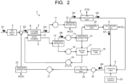
FIG. 2 is a diagram illustrating a modified example of the carbon dioxide conversion apparatus of the embodiment. - Hereinafter, a carbon dioxide conversion apparatus of an embodiment will be described with reference to the drawings. In each embodiment presented below, substantially the same constituent parts are denoted by the same reference signs, and a description thereof may be partially omitted. The drawings are schematic, and the relation of the thickness and planar dimension, a thickness ratio among the parts, and so on may be different from actual ones. Note that a symbol of "~" in the following description indicates a range between an upper limit value and a lower limit value of respective numerical values. In this case, the range of the numerical values includes the upper limit value and the lower limit value.
- A carbon dioxide conversion apparatus of an embodiment includes: a carbon dioxide supply part configured to capture carbon dioxide from a carbon dioxide containing gas and supply the carbon dioxide; a carbon dioxide electrolysis part that includes: a cathode chamber configured to receive the carbon dioxide from the carbon dioxide supply part and reduce the carbon dioxide to produce carbon monoxide; and an anode chamber configured to oxidize an oxidizable substance to produce oxygen and carbon dioxide; a carbon dioxide capture part configured to separate and capture the carbon dioxide from an oxygen-carbon dioxide containing gas to be produced in the anode chamber; a carbon monoxide purification part configured to purify the carbon monoxide from a carbon monoxide containing gas to be produced in the cathode chamber; and an oxidation part configured to perform a reaction between a reducing gas and a carbon dioxide containing gas, the reducing gas being discharged from the carbon monoxide purification part and containing a residual carbon monoxide, and the carbon dioxide containing gas being separated and captured in the carbon dioxide capture part and containing a residual oxygen.
-
FIG. 1 is a diagram illustrating the carbon dioxide conversion apparatus of the embodiment. A carbondioxide conversion apparatus 1 illustrated inFIG. 1 includes a CO2 supply part 2 which captures and supplies CO2 from a carbon dioxide (CO2) containing gas, a CO2 electrolysis part 3 which converts CO2 into carbon monoxide (CO) through electrolysis and reduction, aCO purification part 4 which purifies carbon monoxide (CO) from a gas produced in a cathode chamber of the CO2 electrolysis part 3, a CO2 capturepart 5 which separates and captures carbon dioxide (CO2) from a gas produced in an anode chamber of the CO2 electrolysis part 3, and an oxidation part 6 which reacts a reducing gas containing residual CO discharged from theCO purification part 4 and a CO2 containing gas separated and captured in the CO2 capturepart 5 and containing residual oxygen to convert CO into CO2 and remove the residual oxygen (O2). - The CO2 supply part 2 is configured to separate and capture CO2 from an emission gas G1 containing CO2 (CO2 containing gas) emitted from a thermal power plant, a waste incineration plant, a steel plant, and the like, and supply a CO2 gas G2 having an increased CO2 concentration to the CO2 electrolysis part 3. The CO2 supply part 2 can be constituted by applying, for example, a chemical absorption method of using a chemical absorption solution such as an amine aqueous solution, a physical absorption method of using a physical absorption solution such as methanol or a polyethylene glycol solution, a solid absorption method of using a solid absorbent such as an amine compound, a membrane separation method of using a CO2 separation membrane, a physical adsorption method of using an inorganic substance such as zeolite as an adsorbent, a PSA (Pressure Swing Adsorption method), a TSA (Thermal Swing Adsorption method), or the like is applied. For example, the chemical absorption method and a chemical absorber which use the amine aqueous solution can supply the emission gas G1 to an absorption tower in which the amine aqueous solution is sprayed, and heat the amine aqueous solution absorbing CO2 in a regeneration tower to capture CO2 emitted from the amine aqueous solution.
- The capture method and device of CO2 applied to the CO2 supply part 2 are not particularly limited, and various methods and devices which allow the capture of CO2 from the emission gas (CO2 containing gas) G1 can be applied. The CO2 supply part 2 is connected to a cathode chamber (reducing part) 8 of the CO2 electrolysis part 3 via a
gas mixer 7. The CO2 supply part 2 is configured to supply a CO2 gas G2 to the cathode chamber 8 via thegas mixer 7. - The CO2 electrolysis part 3 is a CO2 electrolysis device having an electrolysis cell, and includes the cathode chamber (reducing part) 8 and an anode chamber (oxidizing part) 9. The cathode chamber 8 includes a reduction electrode (cathode), the anode chamber 9 includes an oxidation electrode (anode), and an electrolytic solution is made to flow through at least the anode chamber 9. A CO2 gas is made to flow through the cathode chamber 8. Examples of the electrolytic solution supplied into the anode chamber 9, include a solution using water (H2O), and an aqueous solution containing an optional electrolyte. Examples of the aqueous solution containing the electrolyte, include an aqueous solution containing at least one ion selected from a phosphate ion (PO4 2-), a borate ion (BO3 3-), a sodium ion (Na+), a potassium ion (K+), a calcium ion (Ca2+), a lithium ion (Li+), a cesium ion (Cs+), a magnesium ion (Mg2+), a chloride ion (Cl-), a hydrogen carbonate ion (HCO3 -), a carbonate ion (CO3 2), and a hydroxide ion (OH-). Examples of the electrolytic solution include an alkaline aqueous solution containing at least one dissolved compound selected from KOH, KHCO3, and K2CO3.
- The cathode chamber 8 can receives the CO2 gas G2 captured in the CO2 supply part 2. The cathode chamber 8 has a gas flow path facing a reduction electrode which is not illustrated in
Fig. 1 . The CO2 gas is supplied to the gas flow path. The anode chamber 9 has a liquid flow path facing an oxidation electrode which is not illustrated inFig. 1 , for example. The electrolytic solution is supplied to the liquid flow path. The cathode chamber 8 and the anode chamber 9 are isolated by adiaphragm 10 capable of moving at least one ion selected from a hydrogen ion (H+), a hydroxide ion (OH-), a carbonate ion (CO3 2-), and a hydrogen carbonate ion (HCO3 -). Examples of thediaphragm 10 include an ion exchange membrane. The CO2 electrolysis part 3 (the CO2 electrolysis device having the electrolysis cell) may have a single electrolysis cell or a structure in which electrolysis cells are arranged and connected in a plane direction, or may have a stack structure in which a plurality of the electrolysis cells are stacked to be integrated. - Each of the reduction electrode and the oxidation electrode of the CO2 electrolysis part 3 are connected to a direct-current power supply which is not illustrated in
Fig. 1 . The reduction electrode and the oxidation electrode of the CO2 electrolysis part 3, can receive a direct current from the direct-current power supply to perform the following electrolytic reaction in the cathode chamber 8 and in the anode chamber 9. The cathode chamber 8 can perform CO2 electrolytic reaction and CO2 reduction reaction, as presented in the following formula (1). The cathode chamber 8 can produce CO and a carbonate ion (CO3 2-) by the CO2 reduction reaction.
2CO2 + 2e- → CO + CO3 2- ... (1)
- The carbonate ion (CO3 2-) produced in the cathode chamber 8 moves to the anode chamber 9 via the
diaphragm 10. The anode chamber 9 can perform an oxidation reaction of the carbonate ion (CO3 2-) produced in the cathode chamber 8 and moved via thediaphragm 10 to produce CO2 and O2, as presented in the following formula (2).
CO3 2- → CO2 + 0.5O2 + 2e- ... (2)
- Moreover, the cathode chamber 8 can perform an electrolytic reaction of H2O in the electrolytic solution to produce hydrogen (H2) and hydroxide ions (OH-), as presented in the following formula (3).
2H2O + 2e- → H2 + 2OH- ... (3)
- The hydroxide ions (OH-) produced in the cathode chamber 8 move to the anode chamber 9 via the
diaphragm 10. Then, the anode chamber 9 can produce water (H2O) and oxygen (O2), as presented in the following formula (4).
2OH- → 0.5O2 + H2O + 2e- ... (4)
- Further, The anode chamber 9 can electrolyze water (H2O) in the electrolytic solution to produce oxygen (O2) and hydrogen ions (H+), as presented in the following formula (5).
2H2O → 4H+ + Q2 + 4e- ... (5)
- The produced hydrogen ions (H+) move to the cathode chamber 8 via the
diaphragm 10. The hydrogen ions (H+) reach the cathode chamber 8, and electrons (e-) reach the cathode chamber 8 through an external circuit, and then the cathode chamber 8 can perform a reaction presented in the following formula (6) to produce hydrogen.
4H+ + 4e- → 2H2 ... (6)
- The cathode chamber 8 can perform the CO2 reduction reaction presented in the formula (1) to produce CO, and can perform the H2O electrolytic reaction presented in the formula (3) and the reaction presented in the formula (6) to produce H2. The CO and H2 produced in the cathode chamber 8 are discharged from the cathode chamber 8 with unreacted CO2 and saturated steam. A mixed gas G3 discharged from the cathode chamber 8 and containing CO, H2, CO2, and the saturated steam (H2O) is cooled by a cooler 11, and thereafter fed to a first gas/
liquid separator 12. The first gas/liquid separator 12 removes the water (H2O) condensed in the cooled mixed gas G3 from the cooled mixed gas G3 to form a mixed gas G4 containing CO, H2, and CO2. The mixed gas G4 is fed to theCO purification part 4. - The
CO purification part 4 can purify the mixed gas G4 to form purified CO. TheCO purification part 4 can be constituted by applying, for example, a CO-PSA (Pressure Swing Adsorption method) of using a copper ion-zeolite adsorbent, a copper ion activated carbon adsorbent, a copper chloride-aluminum-crosslinked polystyrene solid adsorbent, a copper chloride-aluminum-activated carbon adsorbent, or the like, a cuprammonium cleaning method, a copper aluminum chloride complex solution absorption method, a copper chloride-aluminum-polystyrene polymer complex solution absorption method, a low-temperature method, or the like is applied. The purified CO is accommodated in a storage container such as a tank which is not illustrated, for example, or is fed to an organic-substance synthesis reactor such as a methane synthesis reactor, an alcohol synthesizer, or a Fischer-Tropsch reactor which perform a reaction between CO and H2, for example. TheCO purification part 4 constituted by applying the CO-PSA or the like may be replaced by one of these organic-substance synthesis reactors. TheCO purification part 4 can discharge a purification residual gas G5 left by purifying the CO. The purification residual gas G5 contains residual CO, residual H2, and residual CO2. The purification residual gas G5 discharged from theCO purification part 4 is fed to the oxidation part 6. - Meanwhile, The anode chamber 9 of the CO2 electrolysis part 3 can perform the oxidation of a carbonate ion (CO3 2-) and hydroxide ions (OH-) to produce oxygen (O2) and carbon dioxide (CO2), as presented in the formula (2) and formula (4). A gas (O2-CO2 containing gas) containing the O2 and CO2, which is produced in the anode chamber 9, is discharged from the anode chamber 9 with the electrolytic solution. The electrolytic solution containing the O2-CO2 containing gas is fed to a second gas/
liquid separator 13. The second gas/liquid separator 13 can separate the O2-CO2 containing gas from the electrolytic solution. The O2-CO2 containing gas G6 separated by the second gas/liquid separator 13 is cooled to a predetermined temperature by a cooler 14, and thereafter fed to a third gas/liquid separator 15. The electrolytic solution separated by the second gas/liquid separator 13 is cooled to a predetermined temperature by a cooler 16, and thereafter fed to abuffer tank 17. In addition to electrolytic solution, the condensed water (H2O) separated by the third gas/liquid separator 15 is also fed to thebuffer tank 17. The electrolytic solution fed to thebuffer tank 17 is supplied with water from amakeup tank 18 as necessary, and thereafter fed to the anode chamber 9 of the CO2 electrolysis part 3 via apump 19 again. - The O2-CO2 containing gas G6 separated by the second and third gas/
liquid separators O removal part 20, and thereafter fed to the CO2 capture part 5. The H2O removal part 20 can have a water vapor-removing polymer membrane or a water vapor adsorbent such as zeolite, silica gel, mesoporous silica or activated carbon. In the CO2 capture part 5, for example, as a CO2 adsorbent, a primary or secondary amine-supported material, FAU-type zeolite, or GIS-type zeolite is used, and as an organic ligand, a benzene-1,4-dicarbohydroxamic acid is used, at the same time, as an ancillary ligand, an isonicotinic acid is used, and Co-MOF (Metal Organic Frameworks) obtained by a reaction with cobalt nitrate, ZIF-69 (CAS No. 1018477-10-5, chemical formula: C10H6N5O2ClZn), Cubic[Zn4O(piperazine dicarbamate)3], or the like is used, and thereby CO2 is separated and captured by the pressure swing adsorption (PSA) method, or the temperature swing adsorption (TSA) method depending on the adsorbent. - In the CO2 capture part 5, with use of, as an oxygen adsorbent, an organic semiconductor such as a tetracyanoquinodimethane (CAS No. 1518-16-7, chemical formula: (NC)2CC6H4C(CN)2) pore material, O2 may be separated and captured by the pressure swing adsorption (PSA) method or the temperature swing adsorption (TSA) method, resulting in capturing CO2. To CO2 capture
part 5, a faradaic electro-swing reactive adsorption method in which polyvinylferrocene is used as a counter electrode with poly-1,4-anthraquinone used as a CO2 adsorption electrode may be applied. - A gas G7 containing CO2 separated and captured in the CO2 capture part 5 contains residual O2. The gas G7 containing CO2 and the residual O2 is fed to the oxidation part 6. The oxidation part 6 can perform a reaction between the purification residual gas (reducing gas) G5 and the gas G7, the purification residual gas G5 being discharged from the
CO purification part 4 and containing residual CO and unreacted CO2, and the gas G7 being separated and captured in the CO2 capture part 5 and containing CO2 and residual O2. The residual CO in the gas G5 is oxidized by O2 in the gas G7, and converted into CO2. In addition, the O2 in the gas G7 separated and captured in the CO2 capture part 5 is removed. This allows a reduction and moreover a further reduction in an O2 amount in a CO2 gas G8 returned from the oxidation part 6 to the cathode chamber 8 of the CO2 electrolysis part 3. - That is, when the CO2 gas supplied to the cathode chamber 8 of the CO2 electrolysis part 3 contains O2, O2 degrades carbon materials forming the reduction electrode (cathode) disposed in the cathode chamber 8, O2 aggregates metal particles such as gold, silver or copper particles contained as a reduction catalyst in the reduction electrode (cathode), or the like, thereby lowering performance of the reduction electrode. Thus, when the gas G7 containing CO2 separated and captured in the CO2 capture part 5 contains the residual O2, the CO2 gas G8 cannot be fed to the cathode chamber 8 again. In contrast to this, a removal of O2 in the gas G7 separated and captured in the CO2 capture part 5 by the reaction of the purification residual gas (reducing gas) G5 containing the residual CO and the unreacted CO2 and the gas G7 containing CO2 and the residual O2 separated and captured in the CO2 capture part 5 in the oxidation part 6 allows the mixed gas G8 of the gas G7 containing CO2 and the gas G5 containing the unreacted CO2 and CO2 newly produced by the oxidation of CO to be resupplied to the cathode chamber 8 of the CO2 electrolysis part 3 without adversely affecting the cathode chamber 8.
- The CO2 gas G8 is cooled by a cooler 21, and thereafter fed to a fourth gas/
liquid separator 22. Saturated steam and condensed water (H2O) are removed by the fourth gas/liquid separator 22, and thereafter the CO2 gas G8 is fed to thegas mixer 7. The CO2 gas G8 is mixed with the CO2 gas G2 supplied from the CO2 supply part 2 by thegas mixer 7, and is thereafter supplied to the cathode chamber 8 of the CO2 electrolysis part 3. The oxidation part 6 may be constituted by applying a hydrogen-oxygen recombination catalyst or a combustion catalyst such as Ni-Ce2O3-Pt to enable enhancing removability of oxygen. Depending on a residual O2 concentration in the CO2 containing gas G7 supplied from the CO2 capture part 5 or a residual CO concentration in the purification residual gas G5 discharged from theCO purification part 4, as illustrated inFIG. 2 , the carbon dioxide conversion apparatus may have a H2 supply source 23. Moreover, the carbon dioxide conversion apparatus may have an O2 concentration meter 24 and an O2 adsorption part 25 in the middle of a pipe to feed the CO2 gas G8 from the oxidation part 6 to the fourth gas/liquid separator 22. These elements allow a further stable reduction in the O2 concentration in the CO2 gas G8. - To control an amount of water vapor of the CO2 gas G2, and reduce an amount of diffusing water vapor from the electrolytic solution, the CO2 gas may be appropriately humidified in the
gas mixer 7, or a removal amount of water vapor from the CO2 gas G8 may be controlled by an outlet temperature of the cooler 21. For a reduction in load of the cooler 21 and/or a reduction in heating amount of the oxidation part 6, heat may be exchanged between the gas G8 and the gases G5, G7. - As described above, according to the CO2 conversion apparatus 1 of the embodiment, the residual O2 in the CO2 gas G7 separated and captured in the CO2 capture part 5 can be reacted with the residual CO in the purification residual gas G5 in the oxidation part 6 to remove the residual O2 in the CO2 gas G7 and capture the residual CO as CO2. In addition to this, the unreacted CO2 contained in the purification residual gas G5 can be captured. These allow a further stable reduction in the O2 concentration in the CO2 gas G8 adversely affecting the cathode chamber 8 in addition to a promotion of effective use of CO2. That is, the unreacted and reproduced CO2 can be effectively used with electrolysis ability of CO2 by using the CO2 electrolysis part 3 maintained.
- Note that though not described and illustrated in the embodiment, and,
FIG. 1 andFIG. 2 , a blower, a pump, a compressor, or the like may be appropriately disposed, and the flow of the fluid such as gases and liquid may be assisted by them. Further, a part of a discharge gas from the CO2 capture par 5 may be supplied for other uses such as underground storage, EOR, and CO2 fixation (mineralization). Moreover, the O2 gas after separating and capturing CO2 in the CO2 capture par 5 is captured as necessary. - Note that the configurations of the above-described embodiments are applicable in combination with each other, and parts thereof are also replaceable. While certain embodiments of the present invention have been described above, these embodiments have been presented by way of example only, and are not intended to limit the scope of the invention. Indeed these embodiments described herein may be embodied in a variety of other forms; furthermore, various omissions, substitutions, and changes in the form of the embodiments described herein may be made without departing from the spirit of the inventions. The accompanying claims and their equivalents are intended to cover such forms or modifications as would fall within the scope and spirit of the inventions.
Claims (8)
- A carbon dioxide conversion apparatus comprising:a carbon dioxide supply part configured to capture carbon dioxide from a carbon dioxide containing gas and supply the carbon dioxide;a carbon dioxide electrolysis part comprising:a cathode chamber configured to receive the carbon dioxide from the carbon dioxide supply part and reduce the carbon dioxide to produce carbon monoxide; andan anode chamber configured to oxidize an oxidizable substance to produce oxygen and carbon dioxide;a carbon dioxide capture part configured to separate and capture the carbon dioxide from an oxygen-carbon dioxide containing gas to be produced in the anode chamber;a carbon monoxide purification part configured to purify the carbon monoxide from a carbon monoxide containing gas to be produced in the cathode chamber; andan oxidation part configured to perform a reaction between a reducing gas and a carbon dioxide containing gas, the reducing gas being discharged from the carbon monoxide purification part and containing a residual carbon monoxide, and the carbon dioxide containing gas being separated and captured in the carbon dioxide capture part and containing a residual oxygen.
- The apparatus according to claim 1, wherein
the oxidation part is configured to remove the residual oxygen in the carbon dioxide containing gas by the reaction to purify the carbon dioxide containing gas. - The apparatus according to claim 1, wherein
the oxidation part is configured to perform a reaction of the residual carbon monoxide in the reducing gas with the residual oxygen in the carbon dioxide containing gas to produce carbon dioxide. - The apparatus according to claim 2, wherein
the oxidation part is configured to supply the carbon dioxide containing gas purified by the reaction to the cathode chamber of the carbon dioxide electrolysis part. - A carbon dioxide conversion method comprising:reducing carbon dioxide to produce carbon monoxide in a cathode chamber of a carbon dioxide electrolysis part, and oxidizing an oxidizable substance to produce oxygen and carbon dioxide in an anode chamber of the carbon dioxide electrolysis part;separating and capturing carbon dioxide from an oxygen-carbon dioxide containing gas containing the oxygen and the carbon dioxide produced in the anode chamber;purifying the carbon monoxide in a carbon dioxide containing gas containing the carbon monoxide produced in the cathode chamber; andperforming a reaction between a reducing gas and a carbon dioxide containing gas, the reducing gas containing a residual carbon monoxide left by purifying the carbon monoxide, and the carbon dioxide containing gas containing a residual oxygen left by separating and capturing the carbon dioxide.
- The method according to claim 5, wherein
the residual oxygen in the carbon dioxide containing gas is removed by the reaction. - The method according to claim 5, wherein
the residual carbon monoxide in the reducing gas is reacted with the residual oxygen in the carbon dioxide containing gas to produce carbon dioxide by the reaction. - The method according to claim 6, wherein
the carbon dioxide containing gas purified by the reaction is supplied to the cathode chamber.
Applications Claiming Priority (1)
| Application Number | Priority Date | Filing Date | Title |
|---|---|---|---|
| JP2023034938A JP7840894B2 (en) | 2023-03-07 | 2023-03-07 | Carbon dioxide conversion device and carbon dioxide conversion method |
Publications (1)
| Publication Number | Publication Date |
|---|---|
| EP4427832A1 true EP4427832A1 (en) | 2024-09-11 |
Family
ID=89715614
Family Applications (1)
| Application Number | Title | Priority Date | Filing Date |
|---|---|---|---|
| EP24153601.0A Pending EP4427832A1 (en) | 2023-03-07 | 2024-01-24 | Carbon dioxide conversion apparatus and carbon dioxide conversion method |
Country Status (3)
| Country | Link |
|---|---|
| US (1) | US20240301568A1 (en) |
| EP (1) | EP4427832A1 (en) |
| JP (1) | JP7840894B2 (en) |
Citations (3)
| Publication number | Priority date | Publication date | Assignee | Title |
|---|---|---|---|---|
| US20150038741A1 (en) * | 2012-03-05 | 2015-02-05 | Haldor Topsøe A/S | Apparatus for production of high purity carbon monoxide |
| US20160040311A1 (en) * | 2013-03-26 | 2016-02-11 | Haldor Topsøe A/S | A process for producing co from co2 in a solid oxide electrolysis cell |
| EP3670705A1 (en) * | 2018-12-21 | 2020-06-24 | L'air Liquide, Societe Anonyme Pour L'etude Et L'exploitation Des Procedes Georges Claude | Carbon dioxide conversion process |
Family Cites Families (1)
| Publication number | Priority date | Publication date | Assignee | Title |
|---|---|---|---|---|
| JP7297710B2 (en) * | 2020-03-23 | 2023-06-26 | 株式会社東芝 | carbon dioxide reactor |
-
2023
- 2023-03-07 JP JP2023034938A patent/JP7840894B2/en active Active
-
2024
- 2024-01-23 US US18/419,945 patent/US20240301568A1/en active Pending
- 2024-01-24 EP EP24153601.0A patent/EP4427832A1/en active Pending
Patent Citations (3)
| Publication number | Priority date | Publication date | Assignee | Title |
|---|---|---|---|---|
| US20150038741A1 (en) * | 2012-03-05 | 2015-02-05 | Haldor Topsøe A/S | Apparatus for production of high purity carbon monoxide |
| US20160040311A1 (en) * | 2013-03-26 | 2016-02-11 | Haldor Topsøe A/S | A process for producing co from co2 in a solid oxide electrolysis cell |
| EP3670705A1 (en) * | 2018-12-21 | 2020-06-24 | L'air Liquide, Societe Anonyme Pour L'etude Et L'exploitation Des Procedes Georges Claude | Carbon dioxide conversion process |
Non-Patent Citations (1)
| Title |
|---|
| "CAS", Database accession no. 1018477-10-5 |
Also Published As
| Publication number | Publication date |
|---|---|
| JP7840894B2 (en) | 2026-04-06 |
| JP2024126529A (en) | 2024-09-20 |
| US20240301568A1 (en) | 2024-09-12 |
Similar Documents
| Publication | Publication Date | Title |
|---|---|---|
| JP7297710B2 (en) | carbon dioxide reactor | |
| EP1728290A2 (en) | Use of an ammonia storage device in production of energy | |
| EP3818193A1 (en) | Process and system for producing carbon monoxide and dihydrogen from a co2-containing gas | |
| JP2004174370A (en) | Method, apparatus and system for treating gas | |
| JP2025506815A (en) | Electrolytic regeneration of CO2-rich alkaline absorbents for CO2 capture | |
| KR20250028387A (en) | Carbon capture method and device combined with hydrogen production | |
| RU2491109C1 (en) | Air cleaner for sealed manned objects | |
| JP2009269983A (en) | Fuel-cost-saving apparatus of eliminating carbon dioxide | |
| US20240360568A1 (en) | Carbon monoxide production device, carbon dioxide electrolysis device, and carbon dioxide electrolysis method | |
| US20240301568A1 (en) | Carbon dioxide conversion apparatus and carbon dioxide conversion method | |
| JP7666869B2 (en) | Carbon Dioxide Treatment Equipment | |
| US20250289716A1 (en) | Carbon dioxide capture and carbon resource utilization system, for fuel cell, using boil-off gas generated from liquefied natural gas | |
| EP4435148A1 (en) | Carbon dioxide conversion device | |
| US20240301567A1 (en) | Carbon dioxide conversion apparatus and carbon dioxide conversion method | |
| JP7858474B2 (en) | Carbon monoxide production device | |
| JP2023133899A (en) | carbon dioxide electrolyzer | |
| JP7830265B2 (en) | Carbon dioxide conversion device | |
| JP2023079603A (en) | Carbon monoxide production equipment | |
| CN116113624A (en) | Process for producing ethylene oxide | |
| RU2809597C2 (en) | Method and system of producing carbon monoxide and molecular hydrogen from gas containing co2 | |
| US20250043439A1 (en) | Carbon dioxide conversion system | |
| EP4517888A1 (en) | Carbon dioxide capture and carbon resource utilization system for fuel cell and method using same | |
| JP2014201621A (en) | Method of annihilating carbon dioxide and saving fuel consumption | |
| JP2008108621A (en) | Fuel cell power generation system and its carbon dioxide recovery method | |
| JP2026084451A (en) | Carbon dioxide conversion device |
Legal Events
| Date | Code | Title | Description |
|---|---|---|---|
| PUAI | Public reference made under article 153(3) epc to a published international application that has entered the european phase |
Free format text: ORIGINAL CODE: 0009012 |
|
| STAA | Information on the status of an ep patent application or granted ep patent |
Free format text: STATUS: REQUEST FOR EXAMINATION WAS MADE |
|
| 17P | Request for examination filed |
Effective date: 20240124 |
|
| AK | Designated contracting states |
Kind code of ref document: A1 Designated state(s): AL AT BE BG CH CY CZ DE DK EE ES FI FR GB GR HR HU IE IS IT LI LT LU LV MC ME MK MT NL NO PL PT RO RS SE SI SK SM TR |