EP4427825A2 - Loading turntable systems and methods - Google Patents
Loading turntable systems and methods Download PDFInfo
- Publication number
- EP4427825A2 EP4427825A2 EP24190936.5A EP24190936A EP4427825A2 EP 4427825 A2 EP4427825 A2 EP 4427825A2 EP 24190936 A EP24190936 A EP 24190936A EP 4427825 A2 EP4427825 A2 EP 4427825A2
- Authority
- EP
- European Patent Office
- Prior art keywords
- loading
- path
- ride vehicle
- ride
- attraction
- Prior art date
- Legal status (The legal status is an assumption and is not a legal conclusion. Google has not performed a legal analysis and makes no representation as to the accuracy of the status listed.)
- Granted
Links
Images

Classifications
-
- A—HUMAN NECESSITIES
- A63—SPORTS; GAMES; AMUSEMENTS
- A63G—MERRY-GO-ROUNDS; SWINGS; ROCKING-HORSES; CHUTES; SWITCHBACKS; SIMILAR DEVICES FOR PUBLIC AMUSEMENT
- A63G1/00—Roundabouts
-
- A—HUMAN NECESSITIES
- A63—SPORTS; GAMES; AMUSEMENTS
- A63G—MERRY-GO-ROUNDS; SWINGS; ROCKING-HORSES; CHUTES; SWITCHBACKS; SIMILAR DEVICES FOR PUBLIC AMUSEMENT
- A63G21/00—Chutes; Helter-skelters
- A63G21/06—Chutes; Helter-skelters with passing arrangements for cars
-
- A—HUMAN NECESSITIES
- A63—SPORTS; GAMES; AMUSEMENTS
- A63G—MERRY-GO-ROUNDS; SWINGS; ROCKING-HORSES; CHUTES; SWITCHBACKS; SIMILAR DEVICES FOR PUBLIC AMUSEMENT
- A63G25/00—Autocar-like self-drivers; Runways therefor
-
- A—HUMAN NECESSITIES
- A63—SPORTS; GAMES; AMUSEMENTS
- A63G—MERRY-GO-ROUNDS; SWINGS; ROCKING-HORSES; CHUTES; SWITCHBACKS; SIMILAR DEVICES FOR PUBLIC AMUSEMENT
- A63G31/00—Amusement arrangements
-
- A—HUMAN NECESSITIES
- A63—SPORTS; GAMES; AMUSEMENTS
- A63G—MERRY-GO-ROUNDS; SWINGS; ROCKING-HORSES; CHUTES; SWITCHBACKS; SIMILAR DEVICES FOR PUBLIC AMUSEMENT
- A63G7/00—Up-and-down hill tracks; Switchbacks
-
- B—PERFORMING OPERATIONS; TRANSPORTING
- B61—RAILWAYS
- B61B—RAILWAY SYSTEMS; EQUIPMENT THEREFOR NOT OTHERWISE PROVIDED FOR
- B61B13/00—Other railway systems
-
- B—PERFORMING OPERATIONS; TRANSPORTING
- B61—RAILWAYS
- B61K—AUXILIARY EQUIPMENT SPECIALLY ADAPTED FOR RAILWAYS, NOT OTHERWISE PROVIDED FOR
- B61K1/00—Transferring passengers, articles, or freight to and from moving trains; Slipping or coupling vehicles from or to moving trains
Definitions
- the present disclosure relates generally to the field of amusement parks. More particularly, embodiments of the present disclosure relate to systems and methods for implementing flexible passenger loading and unloading time in an attraction of an amusement park.
- some attractions may include loading systems that have ride vehicles continuously moving along a loading zone as passengers unload from a ride vehicle and/or as new passengers load into the ride vehicle.
- some passengers may take a long time to leave the ride vehicle and/or may take a long time to board the ride vehicle. That is, a loading passenger may not be fully boarded and secured within the ride vehicle before the ride vehicle reaches an end of the loading zone. In such instances, movement of all of the ride vehicles through the attraction and/or the loading zone may be affected to give the loading passenger extra time to board the ride vehicle.
- each ride vehicle may come to a complete stop in order to allow the loading passenger extra time in the loading zone to board the ride vehicle.
- Slowing or stopping of the ride vehicles' movement through the attraction may be detrimental to a throughput of the attraction, which can lead to increased waiting times and decreased revenue for the amusement park.
- an attraction loading system in an embodiment, includes a turntable configured to rotate about a vertical axis and a ride vehicle configured to travel along a loading path disposed about a perimeter of the turntable.
- the system also includes a first track switch disposed along the loading path configured to be disposed in a first position to direct the ride vehicle to a main portion of the loading path from an attraction path, and configured to be disposed in a second position to direct the ride vehicle to the main portion of the loading path from a secondary portion of the loading path and a second track switch disposed along the loading path configured to be disposed in a third position to direct the ride vehicle from the main portion of the loading path to the attraction path, and configured to be disposed in a fourth position to direct the ride vehicle from the main portion of the loading path to the secondary portion of the loading path.
- a method includes the steps of directing a ride vehicle along a loading path at a first location of the loading path toward a second location of the loading path; determining an occupancy status of the ride vehicle; and based on the occupancy status of the ride vehicle, controlling a track switch to direct the vehicle along either the loading path or along an attraction path at the second location along the loading path.
- an attraction loading system in an embodiment, includes a loading and/or unloading area comprising a conveyor.
- the system also includes a loading path disposed about a perimeter of the conveyor, wherein a ride vehicle is configured to move along the loading path and an attraction path coupled to the loading path.
- the system also includes a controller configured to direct the ride vehicle from the loading path onto the attraction path based on a first occupancy status of the vehicle or to direct the ride vehicle to re-loop the loading path based on a second occupancy status of the ride vehicle.
- the disclosed embodiments generally relate to a loading system configured to provide for a variable amount of available loading time of passengers into ride vehicles. More specifically, the disclosed embodiments provide for variable passenger loading time into a particular ride vehicle while allowing other ride vehicles to continue at nominal speeds through a loading zone and through the attraction.
- the disclosed loading system may include a loading zone having a turntable configured to continuously rotate about a central vertical axis.
- the loading zone is configured to receive occupied ride vehicles (e.g., passenger-occupied vehicles) at a first radial position (e.g., relative to the central vertical axis) along a perimeter of the turntable.
- the first radial position may include a first track switch.
- the ride vehicles and the turntable are configured to rotate in conjunction from the first radial position to a second radial position (e.g., relative to the central vertical axis along the perimeter of the turntable.
- the first radial position may include a first track switch.
- the rotational speed of the ride vehicles may substantially match the rotational speed of the turntable such that relative movement between the ride vehicles and the turntable may be substantially unperceivable.
- an edge of the turntable may be stationary relative to an edge of the ride vehicle to create a static physical interface, or virtual coupling, between the ride vehicles and the turntable.
- Passengers may unload from the ride vehicles onto the turntable. Once passengers are unloaded from the ride vehicles, new passengers may be directed to load onto the ride vehicles from the turntable.
- the turntable and the ride vehicles may be continuously rotating at a nominal speed as the passengers are unloading and loading the ride vehicles.
- the ride vehicles may continue to move in conjunction with the turntable until the ride vehicles reach the second radial position. If a ride vehicle is occupied with a loaded passenger by the time the ride vehicle reaches the second radial position, the ride vehicle may be directed along an attraction path to begin a ride cycle of the attraction.
- the ride vehicle may be directed to continue rotating (e.g., re-loop through the loading pathway) with the turntable back through to the first radial position.
- the passenger may continue to attempt to board the ride vehicle as the ride vehicle travel is re-looped from the second radial position to the first radial position, and once again from the first radial position to the second radial position.
- the ride vehicle may be directed along the attraction path. In this manner, slower-loading passengers may not cause a disruption to other passengers, as each ride vehicle continues to move at a nominal speed through the loading zone regardless of the occupancy status of the other ride vehicles. Thus, passengers may have an increased amount of available time to load the ride vehicles.
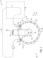
- FIG. 1 is a schematic plan view of an embodiment of a loading zone 10 of a loading system 12.
- the loading zone 10 may be a portion of an overall ride system 14 (e.g., an attraction).
- passengers may load into ride vehicles 16 in the loading zone 10, may travel along an attraction path 18 of the ride system 14, and may arrive back at the loading zone 10 to unload from the ride vehicles 16.
- ride vehicles 16 may be loaded into ride vehicles 16 in the loading zone 10
- attraction path 18 of the ride system 14
- passengers may be exposed to a variety of experiences, such as virtual reality, alternate reality, environment interactions, multiple ride paths, water features, special effects, and so forth.
- portions of the ride system 14, such as the attraction path 18, have been intentionally simplified to focus on aspects of the loading system 12.
- the loading system 12 includes a turntable 20, an entrance ramp 22, a first track switch 24, a second track switch 26, and a variable speed zone 28.
- the turntable 20 is configured to rotate at a substantially constant rotational speed about an axis 40.
- the turntable 20 is substantially circular and rotates in a clockwise direction 41.
- the turntable 20 may be any suitable shape, which may correspond to a theme of the ride system 14, and may rotate in the counter-clockwise direction.
- the turntable 20 may include a stationary portion 42 disposed within a rotational portion 44. That is, the rotational portion 44 may be configured to rotate about the stationary portion 42 while the stationary portion 42 remains stationary.
- the entrance ramp 22 may be any suitable angled path, which may include stairs, a substantially flat angled surface, an escalator, or any combination thereof.
- users may enter the loading zone 10 from an entrance 50, descend the entrance ramp 22 toward a middle portion (e.g., the stationary portion 42) of the turntable 20, and load into the ride vehicle 16.
- users may ascend the entrance ramp 22 toward the entrance 50 to leave the loading zone 10.
- the ride vehicles 16 may enter the loading zone 10 through the variable speed zone 28, which is located at an end of the attraction path 18.
- speeds of the ride vehicles 16 may be augmented and/or may vary as the ride vehicles 16 travel through the variable speed zone 28.
- speeds of the ride vehicles 16 may be adjusted to create a gap (e.g., a bubble) between the ride vehicles 16 or to remove a gap between the ride vehicles 16.
- each ride vehicle 16 may be independently controlled such that each ride vehicle 16 may travel at different speeds for at least a portion of the travel time.
- the ride vehicles 16 may enter a loading path 56, which is disposed about a perimeter of the turntable 20.
- the first track switch 24 in one configuration, permits the ride vehicles 16 from the attraction path 18 to slot into available spaces in the loading path 56 and, alternatively or additionally, changes position to allow ride vehicles 16 that have been re-looped along the loading path 16 to continue along the loading path 16 through the first track switch 24 in another configuration.
- the loading path 56 may include a track or a conveyor, or may be a virtual path for a trackless ride system along which the ride vehicles 16 travel.
- the loading path 56 is a path along which the ride vehicles 16 travel while rotating in conjunction with (i.e., together with or at the same speed as) the turntable 20. As shown, while traveling along the loading path 56, the ride vehicles 16 may rotate at substantially the same rotational speed as the turntable 20. In this manner, a position and orientation of each ride vehicle 16 of the plurality of ride vehicles along the perimeter of the turntable 20 may remain substantially constant.
- each ride vehicle 16 may maintain a temporarily fixed position relative to a circumference of the turntable 20 while traveling through the loading path 56 and while the turntable 20 rotates about its center point such that the orientation of the turntable 20 relative to the ride vehicles 16 (e.g., with seats facing towards a center or alongside an edge of the turntable 20) is substantially maintained.
- each ride vehicle 16 of the plurality of ride vehicles may continuously face the axis 40 of the turntable 20 as the ride vehicles 16 travel along the loading path 56.
- the rotational speed of the turntable 20 as well as the speed of the vehicles in the loading path 56 is less than an average speed of the ride vehicles 16 in the attraction path 18.
- the ride vehicles 16 may traverse the first track switch 24 to enter the loading path 56.
- the first track switch 24 may be in a first position, such as to direct the ride vehicles 16 along a first direction 58 (e.g., a counter-clockwise direction) from the variable speed zone 28 to the loading path 56.
- the first track switch 24 may be in a second position, such as to direct the ride vehicles 16 along a second direction 60 (e.g., a clockwise direction) from other portions of the loading path 56 to continue along the loading path 56.
- the second track switch 26 may be in a third position, such as to direct the ride vehicles 16 along a third direction 62 (e.g., a counter-clockwise direction) from the loading path 56 toward a start of the attraction path 18.
- the second track switch 26 may be in a fourth position, such as to direct the ride vehicles 16 along a fourth direction 64 (e.g., a clockwise direction) to travel further along the loading path 56 toward the first track switch 24.
- the ride vehicles 16 are configured to enter the loading zone 10, and travel along the loading path 56 from the first track switch 24 clockwise 41 toward the second track switch 26 (e.g., a main portion 65 of the loading path 56).
- the ride vehicles 16 may unload from the first ride vehicle 16.
- new passengers may be directed to load into the first ride vehicle 16.
- the new passengers may attempt to load the first ride vehicle 16 as the first ride vehicle 16 travels along the main portion 65. If the new passengers have successfully loaded into the first ride vehicle 16 before the first ride vehicle 16 reaches the second track switch 26, the first ride vehicle 16 may be directed, via the second track switch 26, from the loading path 56 to the attraction path 18.
- the first ride vehicle 16 may be directed, via the second track switch 26, to continue along the loading path 56 toward the first track switch 24 (e.g., along a secondary portion 66 of the loading path 56).
- the secondary portion 66 of the loading path 56 may be disposed beneath the entrance ramp 22. That is, the passengers and the first ride vehicle 16 may travel beneath the entrance ramp 22 while the passengers continue to attempt to load into the first ride vehicle 16.
- the ramp 22 is arranged such that the clearance underneath the ramp 22 is sufficient to permit clearance of the ride vehicles 16 and any unloaded passengers traveling underneath the entrance ramp 22 from the position of the second track switch 26 to the first track switch 24.
- the first ride vehicle 16 may continue to move along the loading path 56 in this manner until the new passengers have loaded into the first ride vehicle 16. Once the passengers have loaded into the first ride vehicle 16, and the first ride vehicle 16 reaches the second track switch 26, the first ride vehicle 16 may be directed from the loading path to the attraction path 18. Thus, the passengers may have increased time to load into the first ride vehicle 16.
- a trackless loading system 12 may use trackless vehicles 16 that travel along a pre-programmed or variable path.
- the system 12 may include a loading station 70 with a conveyer 72 that may be shaped to accommodate irregular loading areas (e.g., peninsula, elongated, or other shapes) and that moves relative to a programmed loading path 56 along which track-based or trackless vehicles 16 travel.
- the loading path 56 aligns with a direction of the conveyor 72 such that the passengers may load into the ride vehicles 16 while positioned on the conveyor 72.
- the ride vehicles 16 may travel along the loading path 16 at a speed approximately equal to a speed of the conveyor 72. To accommodate passengers that may need additional time for loading, the vehicles may be directed via the second track switch 26 onto the secondary portion 66 of the loading path 56 to be re-looped for passenger loading.
- Movement back onto the attraction path 18 and/or re-looping back into the loading path 56 may be controlled by a controller (see FIG. 4 ) of the loading system sending control signals to vehicle controllers of individual ride vehicles 16 based on occupancy status as provided herein. Based on the received control signals, the individual ride vehicles enter the attraction path 18 or re-loop onto the loading path 56 according to the instructions of the control signal.
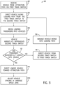
- FIG. 3 is a flow chart of an embodiment of a loading process 80 that may be utilized by the loading system 12. Accordingly, the following discussion may reference FIGS. 1-2 in parallel with FIG. 3 . Further, the following discussion references the progress of a particular ride vehicle 16 through the loading process 80.
- the first ride vehicle 16 may enter the loading zone 10 from the attraction path 18. More specifically, after traveling along the attraction path 18, the ride vehicle 16 may travel through the variable speed zone 28 and traverse the first track switch 24.
- the first ride vehicle 16 may be directed along the main portion 65 of the loading path 56 via the first track switch 24.
- the first track switch 24 may be in the first position by default to direct the first ride vehicle 16 in the first direction 58 from the variable speed zone 28.
- passengers present on the ride vehicle who have completed the attraction via travelling the attraction path 18 may unload from the first ride vehicle 16 while the first ride vehicle 16 continues to move along the main portion 65 of the loading path 56.
- passengers on the ride vehicles 16 may alternatively represent passengers in the loading stage who have not yet entered the attraction path 18 and who are in an incompletely loaded ride vehicle 16.
- ride operators may direct new passenger(s) to load into the first ride vehicle 16 while the first ride vehicle 16 continues to move along the main portion 65 of the loading path 56.
- the first ride vehicle 16 may continue along the loading path 56 from the first track switch 24 to the second track switch 26 while the passengers continue to load into the first ride vehicle 16.
- the first ride vehicle 16 may arrive at the second track switch 26. More specifically, at block 90, the first ride vehicle may approach the second track switch 26.
- a controller and/or operator will determine whether the passengers have successfully loaded into the first ride vehicle 16. For example, in some embodiments, as the first ride vehicle 16 travels along the main portion 65 of the loading path 56 (e.g., during blocks 84, 86, 88, and 90), an operator may observe the passenger unloading and loading the first ride vehicle 16.
- re-looping may be rules-based, such that fully-loaded vehicles are always moved onto the attraction path, empty vehicles are always re-looped, and partially loaded ride vehicles are either re-looped based on a signal indicative of passengers still attempting to load or moved onto the attraction based on a signal that all available passengers are loaded, even if the vehicle 16 has empty seats.
- the occupancy status may be a first status associated with a vehicle permitted to enter the attraction path or a second status associated with a vehicle designated to re-loop onto the loading path 56.
- Providing the load confirmation signal may include pressing a button on a control panel, utilizing a key, utilizing a short range communication device (e.g., an RFID tag), or any other suitable input.
- the load confirmation of the ride first vehicle 16 may be automatic and based on sensor detection of the passengers within the first ride vehicle 16.
- the controller may receive the load confirmation signal and, based on the load confirmation signal, adjust the second track switch 26 to the third position to cause the first ride vehicle 16 to travel in the third direction 62 to the attraction path 18. That is, generally, at block 92, if the passenger(s) have successfully loaded into the first ride vehicle 16 and the controller has received the load confirmation signal, the first ride vehicle 16 may be directed via the second track switch 26 toward the attraction path 18 (block 94). The first ride vehicle 16 may then travel along the attraction path 18 and eventually arrive back at the loading zone 10 (block 82).
- the first ride vehicle 16 may be directed along the loading path 56 from the second track switch 26 toward the first track switch 24 (e.g., along the secondary portion 66 of the loading path 56).
- the loading system 12 may direct the first ride vehicle 16 along the secondary portion 66 of the loading path 56 by default, such as if no input is received from the operator confirming load of the first ride vehicle 16.
- the second track switch 26 may be in the fourth position to direct the first ride vehicle 16 in the fourth direction 64 by default. If no load confirmation signal is received by the controller, the second track switch 26 may remain in the fourth position.
- the first ride vehicle 16 may once again be directed along the main portion 65 of the loading path 56 (block 84).
- a controller may operate to manage merging of the ride vehicles 16 to re-loop onto the main portion 65 of the loading path 56 into available spaces (block 98).
- the ride vehicles 16 moving along the main portion 65 of the loading path 56 may generally move along the loading path 56 at constant intervals. As such, assuming that each ride vehicle 16 is also directed along the attraction path 18 from the second track switch 26, the ride vehicles 16 may also generally travel along the attraction path 18 at constant intervals. However, as described in the embodiments of block 96, the first ride vehicle 16 may be directed from the second track switch 26 along the secondary portion 66 if passengers have not successfully loaded into the first ride vehicle 16, as opposed to being directed along the attraction path 18. Once the ride vehicle 16 traveling along the secondary portion 66 of the loading path 56 reaches the first track switch 24, the first track switch 24 may be placed in the second position to direct the ride vehicle 16 along the second direction 60 to continue along the main portion 65 of the loading path 56. That is, upon reaching the first track switch 24 from the secondary portion 66, the ride vehicle 16 may once again be directed along the loading path 56, as described in the embodiments of block 84.
- an extended interval (e.g., a gap, a bubble, a space), may occur between two adjacent ride vehicles 16 traveling along the attraction path 18 due to the first ride vehicle 16 having been disposed between the pair of adjacent ride vehicles 16 along the loading path 56, being directed to the first track switch 24 instead of to the attraction path 18.
- the extended interval between the pair of adjacent ride vehicles 16 may be normalized. That is, the interval between the adjacent ride vehicles 16 may become substantially uniform with the intervals between other ride vehicles 16 traveling through the variable speed zone 28. This may be accomplished by increasing or decreasing a speed of one or more ride vehicles 16 traveling through the variable speed zone 28.
- the adjustment in spacing may also be coordinated with re-looping of upcoming vehicles 16 from the secondary portion 66 of the loading path 56 into the main portion 65 of the loading path 56.
- a speed of a second ride vehicle 16 traveling through the variable speed zone 28 may be adjusted to create a space for the first ride vehicle 16 traveling along the secondary portion 66 toward the first track switch 24.
- the ride vehicles 16 may arrive to the variable speed zone 28 from the attraction path 18 before moving to the loading path 56. While in the variable speed zone 28, the ride vehicles 16 may travel at a nominal speed to transition to the loading path 56 at regular intervals.
- a speed of one or more vehicles 16 e.g., the second ride vehicle
- a speed of one or more vehicles 16 within the variable speed zone 28 may be adjusted to approximately double an interval between a pair of adjacent ride vehicles 16.
- the first ride vehicle 16 traveling from the second track switch 26 may be positioned between the pair of adjacent ride vehicles 16 of the variable speed zone 28 as the pair of adjacent ride vehicles 16 transitions to the loading path 56.
- the act of the first ride vehicle 16 being directed along the secondary portion 66 from the second track switch 24 may feed into the controller managing the merging in block 98.
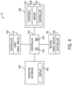
- FIG. 4 is a block diagram of the loading system 12.
- the loading system includes a turntable assembly 106 that drives rotation of the turntable 20 via a motor 108 and a turntable controller 110.
- the turntable controller 110 may be coupled to a central ride controller 120, and may communicate through a wireless network (e.g., wireless local area networks [WLAN], wireless wide area networks [WWAN], near field communication [NFC]) and/or through a wired network (e.g., local area networks [LAN], wide area networks [WAN]).
- the controller 120 includes a processor 124 and a memory 126. It should be understood that other disclosed components of the loading system 12 may also include a memory and processor and may operate to execute processor-based instructions stored in a memory.
- the central ride controller 120 may also control vehicle movement, variable vehicle movement (e.g., through the variable speed zone 28), merging from the secondary portion 66 of the loading path 56 during re-looping, and may communicate with the first track switch 24 and the second track switch 26 and their respective controllers 130, 132 to direct movement of the ride vehicles 16 between the attraction path 18 and the loading path 56.
- the controller 120 may receive a signal, or data, that one or more ride vehicles 16 approaching the second track switch 26 have an occupancy status associated with being moved onto the attraction path 18.
- the second track switch 26 receives a signal to switch to (or remain in) an attraction path position.
- the second track switch 26 receives a signal from the controller 120 to move to (or remain in) a position to re-loop the ride vehicle 16.
- the controller 120 may keep track of all vehicles 16 of the ride system 14 and their respective locations either on the loading path 56 or on the attraction path 18. Further, the controller 120 may control re-looping of empty vehicles 16 or entry into a maintenance or holding path to maintain a desired or fixed number of vehicles 16 in the attraction path 18. That is, the controller 120 may log entry of vehicles 18 onto the attraction path 18 and may prevent too many vehicles 16 from being on the attraction path 18 by directing vehicles 16 to re-loop until space is available.
- the central controller 120 may permit operator input via an operator interface 140, which may include a display 142.
- an operator may send one or more signals to the central controller 120 via the operator interface 140 to operate the loading system 12 as discussed herein.
- the embodiments disclosed herein include systems and methods configured to provide variable loading time for passengers loading into ride vehicles.
- the disclosed embodiments include an attraction with a loading zone having ride vehicles configured to rotate in conjunction with a turntable while passengers unload and load the ride vehicles.
- passengers have a set amount of time to load into the ride vehicles as the ride vehicles travel through the loading zone.
- the passenger and the ride vehicle may be re-looped to a start of the loading zone.
- the re-looping of the ride vehicle may be implemented without negatively affecting the progress of other ride vehicles through the loading zone or through the attraction.
- An attraction loading system in an aspect comprises a turntable configured to rotate about a vertical axis, a ride vehicle configured to travel along a loading path disposed about a perimeter of the turntable, a first track switch disposed along the loading path configured to be disposed in a first position to direct the ride vehicle to a main portion of the loading path from an attraction path, and configured to be disposed in a second position to direct the ride vehicle to the main portion of the loading path from a secondary portion of the loading path; and a second track switch disposed along the loading path configured to be disposed in a third position to direct the ride vehicle from the main portion of the loading path to the attraction path, and configured to be disposed in a fourth position to direct the ride vehicle from the main portion of the loading path to the secondary portion of the loading path.
- the ride vehicle travels along the loading path at a speed aligned with a rotational speed of the turntable such that the ride vehicle maintains a fixed distance from a particular point on an edge of the turntable while traveling along the loading path.
- the system comprises a fixed platform positioned coaxially within the turntable and that does not rotate with the turntable.
- the system may comprise a passenger entrance path that connects to the fixed platform.
- the system comprises a ride controller configured to control a speed of the ride vehicle in the attraction path to adjust a spacing of the ride vehicle relative to another ride vehicle.
- the system may comprise a variable speed zone disposed at an end of the attraction path, wherein the ride vehicle may be configured to move through variable speed zone, and wherein the first track switch may be configured to be disposed in the first position to direct the ride vehicle from the variable speed zone to the main portion of the loading path.
- the system comprises a ride controller configured to control a speed of the ride vehicle in the attraction path to adjust a spacing of the ride vehicle relative to another ride vehicle, and a variable speed zone disposed at an end of the attraction path, wherein the ride vehicle is configured to move through variable speed zone, and wherein the first track switch is configured to be disposed in the first position to direct the ride vehicle from the variable speed zone to the main portion of the loading path, wherein the ride controller is configured to control the speed of the ride vehicle while the ride vehicle is in the variable speed zone to adjust the spacing of the ride vehicle relative to a second ride vehicle within the variable speed zone.
- the ride controller may be configured to control the speed of the ride vehicle, control a second speed of the second ride vehicle, or both, within the variable speed zone to increase a distance between the ride vehicle and the second ride vehicle within the variable speed zone. Further, the ride controller may be configured to control the speed of the ride vehicle, control a second speed of the second ride vehicle, or both, within the variable speed zone to decrease a distance between the ride vehicle and the second ride vehicle within the variable speed zone.
- the system comprises a ride controller, wherein the ride controller is configured to receive a load confirmation signal associated with the ride vehicle while the ride vehicle travels along the main portion of the loading path, and wherein the ride controller is configured to adjust the position of the second track switch based on whether the ride controller receives the loading confirmation signal.
- the ride controller may be configured to position the second track switch in the third position to direct the ride vehicle from the main portion of the loading path to the attraction path.
- the ride controller may be configured to position the second track switch in the fourth position to direct the ride vehicle from the main portion of the loading path to the secondary portion of the loading path
- a method to load passengers into ride vehicles comprises directing a ride vehicle along a loading path at a first location of the loading path toward a second location of the loading path, determining an occupancy status of the ride vehicle; and based on the occupancy status of the ride vehicle, controlling a track switch to direct the vehicle along either the loading path or along an attraction path at the second location along the loading path.
- determining the occupancy status may comprise determining whether the passengers are loading into the ride vehicle or have loaded into the ride vehicle.
- controlling the track switch may comprise controlling the track switch to direct the ride vehicle along the loading path at the second location based on determining that the passengers are loading into the ride vehicle.
- controlling the track switch may comprise controlling the track switch to direct the ride vehicle along the attraction path at the second location based on determining that the passengers have loaded into the ride vehicle.
- directing the ride vehicle along the loading path at the first location comprises controlling a second track switch to direct the ride vehicle along a main portion of the loading path from a secondary portion of the loading path or along the main portion of the loading path from a variable speed zone of the attraction path.
- an attraction loading system comprises a turntable configured to rotate about a vertical axis, a loading path disposed about a perimeter of the turntable, wherein a ride vehicle is configured to move along the loading path, a first track switch disposed along the loading path, wherein the first track switch is configured to direct the ride vehicle to a main portion of the loading path from either a secondary portion of the loading path or an attraction path, and a second track switch disposed along the loading path, wherein the second track switch is configured to direct the ride vehicle from the main portion of the loading path to either the secondary portion of the loading path or the attraction path.
- the system comprises a ride controller, wherein the ride controller is configured to control a speed of the ride vehicle along the loading path such that a speed of the ride vehicle along the loading path substantially matches a rotational speed of the turntable.
- the system comprises a variable speed zone disposed at an end of the attraction path, wherein the first track switch is configured to direct the ride vehicle from to the main portion of the loading path from either the secondary portion of the loading path or the variable speed zone of the attraction path; and a ride controller configured to adjust a speed of the ride vehicle through the variable speed zone based on a presence of a second ride vehicle disposed along the secondary portion of the loading path.
- an attraction loading system comprises a loading and/or unloading area comprising a conveyor, a loading path disposed about a perimeter of the conveyor, wherein a ride vehicle is configured to move along the loading path, an attraction path coupled to the loading path, and a controller configured to direct the ride vehicle from the loading path onto the attraction path based on a first occupancy status of the vehicle or to direct the ride vehicle to re-loop the loading path based on a second occupancy status of the ride vehicle.
Landscapes
- Engineering & Computer Science (AREA)
- Mechanical Engineering (AREA)
- Transportation (AREA)
- Motorcycle And Bicycle Frame (AREA)
- Escalators And Moving Walkways (AREA)
- Mobile Radio Communication Systems (AREA)
- Train Traffic Observation, Control, And Security (AREA)
- Specific Conveyance Elements (AREA)
- Electric Propulsion And Braking For Vehicles (AREA)
- Intermediate Stations On Conveyors (AREA)
Abstract
Description
- This application claims the benefit of
U.S. Provisional Application No. 62/809,323, entitled "LOADING TURNTABLE SYSTEMS AND METHODS," filed February 22, 2019 - The present disclosure relates generally to the field of amusement parks. More particularly, embodiments of the present disclosure relate to systems and methods for implementing flexible passenger loading and unloading time in an attraction of an amusement park.
- Recently, there has been a growing interest in increasing an efficiency of loading passengers into ride vehicles of attractions of amusement parks. For example, some attractions may include loading systems that have ride vehicles continuously moving along a loading zone as passengers unload from a ride vehicle and/or as new passengers load into the ride vehicle. However, some passengers may take a long time to leave the ride vehicle and/or may take a long time to board the ride vehicle. That is, a loading passenger may not be fully boarded and secured within the ride vehicle before the ride vehicle reaches an end of the loading zone. In such instances, movement of all of the ride vehicles through the attraction and/or the loading zone may be affected to give the loading passenger extra time to board the ride vehicle. For example, in one scenario, each ride vehicle may come to a complete stop in order to allow the loading passenger extra time in the loading zone to board the ride vehicle. Slowing or stopping of the ride vehicles' movement through the attraction may be detrimental to a throughput of the attraction, which can lead to increased waiting times and decreased revenue for the amusement park.
- Certain embodiments commensurate in scope with the originally claimed subject matter are summarized below. These embodiments are not intended to limit the scope of the claimed subject matter, but rather these embodiments are intended only to provide a brief summary of possible forms of the subject matter. Indeed, the subject matter may encompass a variety of forms that may be similar to or different from the embodiments set forth below.
- In an embodiment, an attraction loading system is provided that includes a turntable configured to rotate about a vertical axis and a ride vehicle configured to travel along a loading path disposed about a perimeter of the turntable. The system also includes a first track switch disposed along the loading path configured to be disposed in a first position to direct the ride vehicle to a main portion of the loading path from an attraction path, and configured to be disposed in a second position to direct the ride vehicle to the main portion of the loading path from a secondary portion of the loading path and a second track switch disposed along the loading path configured to be disposed in a third position to direct the ride vehicle from the main portion of the loading path to the attraction path, and configured to be disposed in a fourth position to direct the ride vehicle from the main portion of the loading path to the secondary portion of the loading path.
- In an embodiment, a method is provided that includes the steps of directing a ride vehicle along a loading path at a first location of the loading path toward a second location of the loading path; determining an occupancy status of the ride vehicle; and based on the occupancy status of the ride vehicle, controlling a track switch to direct the vehicle along either the loading path or along an attraction path at the second location along the loading path.
- In an embodiment, an attraction loading system is provided that includes a turntable configured to rotate about a vertical axis. The system also includes a loading path disposed about a perimeter of the turntable, wherein a ride vehicle is configured to move along the loading path. The system also includes a first track switch disposed along the loading path, wherein the first track switch is configured to direct the ride vehicle from to a main portion of the loading path from either a secondary portion of the loading path or an attraction path and a second track switch disposed along the loading path, wherein the second track switch is configured to direct the ride vehicle from the main portion of the loading path to either the secondary portion of the loading path or an attraction path.
- In an embodiment, an attraction loading system is provided that includes a loading and/or unloading area comprising a conveyor. The system also includes a loading path disposed about a perimeter of the conveyor, wherein a ride vehicle is configured to move along the loading path and an attraction path coupled to the loading path. The system also includes a controller configured to direct the ride vehicle from the loading path onto the attraction path based on a first occupancy status of the vehicle or to direct the ride vehicle to re-loop the loading path based on a second occupancy status of the ride vehicle.
- These and other features, aspects, and advantages of the present disclosure will become better understood when the following detailed description is read with reference to the accompanying drawings in which like characters represent like parts throughout the drawings, wherein:
-
FIG. 1 is a schematic plan view of an embodiment of the loading system; -
FIG. 2 is a schematic plan view of an embodiment of the loading system; -
FIG. 3 is a flow diagram of a method of operating the loading system; and -
FIG. 4 is a block diagram of an embodiment of the loading system. - When introducing elements of various embodiments of the present disclosure, the articles "a," "an," and "the" are intended to mean that there are one or more of the elements. The terms "comprising," "including," and "having" are intended to be inclusive and mean that there may be additional elements other than the listed elements. Additionally, it should be understood that references to "one embodiment" or "an embodiment" of the present disclosure are not intended to be interpreted as excluding the existence of additional embodiments that also incorporate the recited features.
- The disclosed embodiments generally relate to a loading system configured to provide for a variable amount of available loading time of passengers into ride vehicles. More specifically, the disclosed embodiments provide for variable passenger loading time into a particular ride vehicle while allowing other ride vehicles to continue at nominal speeds through a loading zone and through the attraction. For example, the disclosed loading system may include a loading zone having a turntable configured to continuously rotate about a central vertical axis. The loading zone is configured to receive occupied ride vehicles (e.g., passenger-occupied vehicles) at a first radial position (e.g., relative to the central vertical axis) along a perimeter of the turntable. In some embodiments, the first radial position may include a first track switch. The ride vehicles and the turntable are configured to rotate in conjunction from the first radial position to a second radial position (e.g., relative to the central vertical axis along the perimeter of the turntable. In some embodiments, the first radial position may include a first track switch. The rotational speed of the ride vehicles may substantially match the rotational speed of the turntable such that relative movement between the ride vehicles and the turntable may be substantially unperceivable. In other words, an edge of the turntable may be stationary relative to an edge of the ride vehicle to create a static physical interface, or virtual coupling, between the ride vehicles and the turntable.
- Passengers may unload from the ride vehicles onto the turntable. Once passengers are unloaded from the ride vehicles, new passengers may be directed to load onto the ride vehicles from the turntable. Generally, in order to increase a throughput of users through the attraction, the turntable and the ride vehicles may be continuously rotating at a nominal speed as the passengers are unloading and loading the ride vehicles. The ride vehicles may continue to move in conjunction with the turntable until the ride vehicles reach the second radial position. If a ride vehicle is occupied with a loaded passenger by the time the ride vehicle reaches the second radial position, the ride vehicle may be directed along an attraction path to begin a ride cycle of the attraction. However, if the ride vehicle is unoccupied and a passenger is still attempting to load the ride vehicle by the time the ride vehicle reaches the second radial position, the ride vehicle may be directed to continue rotating (e.g., re-loop through the loading pathway) with the turntable back through to the first radial position. The passenger may continue to attempt to board the ride vehicle as the ride vehicle travel is re-looped from the second radial position to the first radial position, and once again from the first radial position to the second radial position. Once the passenger has successfully loaded into the ride vehicle, and the ride vehicle reaches the second radial position, the ride vehicle may be directed along the attraction path. In this manner, slower-loading passengers may not cause a disruption to other passengers, as each ride vehicle continues to move at a nominal speed through the loading zone regardless of the occupancy status of the other ride vehicles. Thus, passengers may have an increased amount of available time to load the ride vehicles.
- Turning now to the figures,
FIG. 1 is a schematic plan view of an embodiment of aloading zone 10 of aloading system 12. As shown, theloading zone 10 may be a portion of an overall ride system 14 (e.g., an attraction). For example, passengers may load intoride vehicles 16 in theloading zone 10, may travel along anattraction path 18 of theride system 14, and may arrive back at theloading zone 10 to unload from theride vehicles 16. While traveling along theattraction path 18, passengers may be exposed to a variety of experiences, such as virtual reality, alternate reality, environment interactions, multiple ride paths, water features, special effects, and so forth. It should be noted that portions of theride system 14, such as theattraction path 18, have been intentionally simplified to focus on aspects of theloading system 12. - The
loading system 12 includes aturntable 20, anentrance ramp 22, afirst track switch 24, asecond track switch 26, and avariable speed zone 28. Theturntable 20 is configured to rotate at a substantially constant rotational speed about an axis 40. In the currently illustrated embodiment, theturntable 20 is substantially circular and rotates in aclockwise direction 41. However, theturntable 20 may be any suitable shape, which may correspond to a theme of theride system 14, and may rotate in the counter-clockwise direction. In some embodiments, theturntable 20 may include astationary portion 42 disposed within arotational portion 44. That is, therotational portion 44 may be configured to rotate about thestationary portion 42 while thestationary portion 42 remains stationary. Theentrance ramp 22 may be any suitable angled path, which may include stairs, a substantially flat angled surface, an escalator, or any combination thereof. Generally, users may enter theloading zone 10 from anentrance 50, descend theentrance ramp 22 toward a middle portion (e.g., the stationary portion 42) of theturntable 20, and load into theride vehicle 16. Similarly, users may ascend theentrance ramp 22 toward theentrance 50 to leave theloading zone 10. - The
ride vehicles 16 may enter theloading zone 10 through thevariable speed zone 28, which is located at an end of theattraction path 18. As discussed in further detail below, speeds of theride vehicles 16 may be augmented and/or may vary as theride vehicles 16 travel through thevariable speed zone 28. For example, in some embodiments, speeds of theride vehicles 16 may be adjusted to create a gap (e.g., a bubble) between theride vehicles 16 or to remove a gap between theride vehicles 16. Indeed, eachride vehicle 16 may be independently controlled such that eachride vehicle 16 may travel at different speeds for at least a portion of the travel time. - From the
variable speed zone 28, theride vehicles 16 may enter aloading path 56, which is disposed about a perimeter of theturntable 20. Thefirst track switch 24, in one configuration, permits theride vehicles 16 from theattraction path 18 to slot into available spaces in theloading path 56 and, alternatively or additionally, changes position to allowride vehicles 16 that have been re-looped along theloading path 16 to continue along theloading path 16 through thefirst track switch 24 in another configuration. - While the
ride vehicle 16 is moving along theloading path 56, passengers may load and unload theride vehicles 16. Theloading path 56 may include a track or a conveyor, or may be a virtual path for a trackless ride system along which theride vehicles 16 travel. In some embodiments, theloading path 56 is a path along which theride vehicles 16 travel while rotating in conjunction with (i.e., together with or at the same speed as) theturntable 20. As shown, while traveling along theloading path 56, theride vehicles 16 may rotate at substantially the same rotational speed as theturntable 20. In this manner, a position and orientation of eachride vehicle 16 of the plurality of ride vehicles along the perimeter of theturntable 20 may remain substantially constant. In other words, eachride vehicle 16 may maintain a temporarily fixed position relative to a circumference of theturntable 20 while traveling through theloading path 56 and while theturntable 20 rotates about its center point such that the orientation of theturntable 20 relative to the ride vehicles 16 (e.g., with seats facing towards a center or alongside an edge of the turntable 20) is substantially maintained. For example, in the currently illustrated embodiment having a substantiallycircular turntable 20, eachride vehicle 16 of the plurality of ride vehicles may continuously face the axis 40 of theturntable 20 as theride vehicles 16 travel along theloading path 56. In certain embodiments, the rotational speed of theturntable 20 as well as the speed of the vehicles in theloading path 56 is less than an average speed of theride vehicles 16 in theattraction path 18. - From the
variable speed zone 28, theride vehicles 16 may traverse thefirst track switch 24 to enter theloading path 56. Indeed, as discussed in further detail below, thefirst track switch 24 may be in a first position, such as to direct theride vehicles 16 along a first direction 58 (e.g., a counter-clockwise direction) from thevariable speed zone 28 to theloading path 56. Alternatively, thefirst track switch 24 may be in a second position, such as to direct theride vehicles 16 along a second direction 60 (e.g., a clockwise direction) from other portions of theloading path 56 to continue along theloading path 56. Similarly, thesecond track switch 26 may be in a third position, such as to direct theride vehicles 16 along a third direction 62 (e.g., a counter-clockwise direction) from theloading path 56 toward a start of theattraction path 18. Alternatively, thesecond track switch 26 may be in a fourth position, such as to direct theride vehicles 16 along a fourth direction 64 (e.g., a clockwise direction) to travel further along theloading path 56 toward thefirst track switch 24. - In the depicted embodiment, the
ride vehicles 16 are configured to enter theloading zone 10, and travel along theloading path 56 from thefirst track switch 24 clockwise 41 toward the second track switch 26 (e.g., amain portion 65 of the loading path 56). As afirst ride vehicle 16 travels along theloading path 56, passengers may unload from thefirst ride vehicle 16. Once the passengers are unloaded from thefirst ride vehicle 16, new passengers may be directed to load into thefirst ride vehicle 16. The new passengers may attempt to load thefirst ride vehicle 16 as thefirst ride vehicle 16 travels along themain portion 65. If the new passengers have successfully loaded into thefirst ride vehicle 16 before thefirst ride vehicle 16 reaches thesecond track switch 26, thefirst ride vehicle 16 may be directed, via thesecond track switch 26, from theloading path 56 to theattraction path 18. However, if the new passengers have not successfully loaded into thefirst ride vehicle 16 before thefirst ride vehicle 16 reaches thesecond track switch 26, thefirst ride vehicle 16 may be directed, via thesecond track switch 26, to continue along theloading path 56 toward the first track switch 24 (e.g., along asecondary portion 66 of the loading path 56). Indeed, as shown, thesecondary portion 66 of theloading path 56 may be disposed beneath theentrance ramp 22. That is, the passengers and thefirst ride vehicle 16 may travel beneath theentrance ramp 22 while the passengers continue to attempt to load into thefirst ride vehicle 16. Accordingly, theramp 22 is arranged such that the clearance underneath theramp 22 is sufficient to permit clearance of theride vehicles 16 and any unloaded passengers traveling underneath theentrance ramp 22 from the position of thesecond track switch 26 to thefirst track switch 24. - The
first ride vehicle 16 may continue to move along theloading path 56 in this manner until the new passengers have loaded into thefirst ride vehicle 16. Once the passengers have loaded into thefirst ride vehicle 16, and thefirst ride vehicle 16 reaches thesecond track switch 26, thefirst ride vehicle 16 may be directed from the loading path to theattraction path 18. Thus, the passengers may have increased time to load into thefirst ride vehicle 16. - While
FIG. 1 is discussed in reference to a track-basedloading system 12 that uses aturntable 20, it should be understood that other loading/unloading arrangements may also be used in conjunction with the present techniques. For example, atrackless loading system 12 may usetrackless vehicles 16 that travel along a pre-programmed or variable path. In certain embodiments, as illustrated inFIG. 2 , thesystem 12 may include aloading station 70 with aconveyer 72 that may be shaped to accommodate irregular loading areas (e.g., peninsula, elongated, or other shapes) and that moves relative to a programmedloading path 56 along which track-based ortrackless vehicles 16 travel. Theloading path 56 aligns with a direction of theconveyor 72 such that the passengers may load into theride vehicles 16 while positioned on theconveyor 72. Theride vehicles 16 may travel along theloading path 16 at a speed approximately equal to a speed of theconveyor 72. To accommodate passengers that may need additional time for loading, the vehicles may be directed via thesecond track switch 26 onto thesecondary portion 66 of theloading path 56 to be re-looped for passenger loading. - Movement back onto the
attraction path 18 and/or re-looping back into theloading path 56 may be controlled by a controller (seeFIG. 4 ) of the loading system sending control signals to vehicle controllers ofindividual ride vehicles 16 based on occupancy status as provided herein. Based on the received control signals, the individual ride vehicles enter theattraction path 18 or re-loop onto theloading path 56 according to the instructions of the control signal. - Keeping this in mind,
FIG. 3 is a flow chart of an embodiment of aloading process 80 that may be utilized by theloading system 12. Accordingly, the following discussion may referenceFIGS. 1-2 in parallel withFIG. 3 . Further, the following discussion references the progress of aparticular ride vehicle 16 through theloading process 80. - At
block 82, thefirst ride vehicle 16 may enter theloading zone 10 from theattraction path 18. More specifically, after traveling along theattraction path 18, theride vehicle 16 may travel through thevariable speed zone 28 and traverse thefirst track switch 24. - At
block 84, thefirst ride vehicle 16 may be directed along themain portion 65 of theloading path 56 via thefirst track switch 24. Particularly, thefirst track switch 24 may be in the first position by default to direct thefirst ride vehicle 16 in thefirst direction 58 from thevariable speed zone 28. After passing thefirst track switch 24 into theloading path 56, passengers present on the ride vehicle who have completed the attraction via travelling theattraction path 18 may unload from thefirst ride vehicle 16 while thefirst ride vehicle 16 continues to move along themain portion 65 of theloading path 56. However, it should be understood that passengers on theride vehicles 16 may alternatively represent passengers in the loading stage who have not yet entered theattraction path 18 and who are in an incompletely loadedride vehicle 16. Atblock 88, ride operators may direct new passenger(s) to load into thefirst ride vehicle 16 while thefirst ride vehicle 16 continues to move along themain portion 65 of theloading path 56. - The
first ride vehicle 16 may continue along theloading path 56 from thefirst track switch 24 to thesecond track switch 26 while the passengers continue to load into thefirst ride vehicle 16. Atblock 90, thefirst ride vehicle 16 may arrive at thesecond track switch 26. More specifically, atblock 90, the first ride vehicle may approach thesecond track switch 26. Atblock 92, as thefirst ride vehicle 16 approaches thesecond track switch 26, a controller and/or operator will determine whether the passengers have successfully loaded into thefirst ride vehicle 16. For example, in some embodiments, as thefirst ride vehicle 16 travels along themain portion 65 of the loading path 56 (e.g., duringblocks first ride vehicle 16. Once the passengers have successfully loaded into thefirst ride vehicle 16, the operator may provide a load confirmation signal to theloading system 12 to confirm an occupancy status of the first ride vehicle 16 ( e.g., fully loaded, empty, or partially loaded). In certain embodiments, re-looping may be rules-based, such that fully-loaded vehicles are always moved onto the attraction path, empty vehicles are always re-looped, and partially loaded ride vehicles are either re-looped based on a signal indicative of passengers still attempting to load or moved onto the attraction based on a signal that all available passengers are loaded, even if thevehicle 16 has empty seats. In certain embodiments, the occupancy status may be a first status associated with a vehicle permitted to enter the attraction path or a second status associated with a vehicle designated to re-loop onto theloading path 56. Providing the load confirmation signal may include pressing a button on a control panel, utilizing a key, utilizing a short range communication device (e.g., an RFID tag), or any other suitable input. Alternatively or additionally, the load confirmation of the ridefirst vehicle 16 may be automatic and based on sensor detection of the passengers within thefirst ride vehicle 16. The controller (e.g., an attraction controller and/or a respective controller of the first ride vehicle 16) may receive the load confirmation signal and, based on the load confirmation signal, adjust thesecond track switch 26 to the third position to cause thefirst ride vehicle 16 to travel in thethird direction 62 to theattraction path 18. That is, generally, atblock 92, if the passenger(s) have successfully loaded into thefirst ride vehicle 16 and the controller has received the load confirmation signal, thefirst ride vehicle 16 may be directed via thesecond track switch 26 toward the attraction path 18 (block 94). Thefirst ride vehicle 16 may then travel along theattraction path 18 and eventually arrive back at the loading zone 10 (block 82). - However, at
block 90, if the controller and/or operator determines that the passenger(s) have not successfully loaded into thefirst ride vehicle 16, atblock 96, thefirst ride vehicle 16 may be directed along theloading path 56 from thesecond track switch 26 toward the first track switch 24 (e.g., along thesecondary portion 66 of the loading path 56). For example, in some embodiments, theloading system 12 may direct thefirst ride vehicle 16 along thesecondary portion 66 of theloading path 56 by default, such as if no input is received from the operator confirming load of thefirst ride vehicle 16. More specifically, thesecond track switch 26 may be in the fourth position to direct thefirst ride vehicle 16 in thefourth direction 64 by default. If no load confirmation signal is received by the controller, thesecond track switch 26 may remain in the fourth position. After traveling along thesecondary portion 66 of theloading path 56, thefirst ride vehicle 16 may once again be directed along themain portion 65 of the loading path 56 (block 84). A controller may operate to manage merging of theride vehicles 16 to re-loop onto themain portion 65 of theloading path 56 into available spaces (block 98). - The
ride vehicles 16 moving along themain portion 65 of theloading path 56 may generally move along theloading path 56 at constant intervals. As such, assuming that eachride vehicle 16 is also directed along theattraction path 18 from thesecond track switch 26, theride vehicles 16 may also generally travel along theattraction path 18 at constant intervals. However, as described in the embodiments ofblock 96, thefirst ride vehicle 16 may be directed from thesecond track switch 26 along thesecondary portion 66 if passengers have not successfully loaded into thefirst ride vehicle 16, as opposed to being directed along theattraction path 18. Once theride vehicle 16 traveling along thesecondary portion 66 of theloading path 56 reaches thefirst track switch 24, thefirst track switch 24 may be placed in the second position to direct theride vehicle 16 along thesecond direction 60 to continue along themain portion 65 of theloading path 56. That is, upon reaching thefirst track switch 24 from thesecondary portion 66, theride vehicle 16 may once again be directed along theloading path 56, as described in the embodiments ofblock 84. - In such embodiments, an extended interval (e.g., a gap, a bubble, a space), may occur between two
adjacent ride vehicles 16 traveling along theattraction path 18 due to thefirst ride vehicle 16 having been disposed between the pair ofadjacent ride vehicles 16 along theloading path 56, being directed to thefirst track switch 24 instead of to theattraction path 18. Accordingly, inblock 100, when the pair ofadjacent ride vehicles 16 traveling along theattraction path 18 with the extended interval arrives to thevariable speed zone 28, the extended interval between the pair ofadjacent ride vehicles 16 may be normalized. That is, the interval between theadjacent ride vehicles 16 may become substantially uniform with the intervals betweenother ride vehicles 16 traveling through thevariable speed zone 28. This may be accomplished by increasing or decreasing a speed of one ormore ride vehicles 16 traveling through thevariable speed zone 28. The adjustment in spacing may also be coordinated with re-looping ofupcoming vehicles 16 from thesecondary portion 66 of theloading path 56 into themain portion 65 of theloading path 56. - At
block 100, a speed of asecond ride vehicle 16 traveling through thevariable speed zone 28 may be adjusted to create a space for thefirst ride vehicle 16 traveling along thesecondary portion 66 toward thefirst track switch 24. Generally, theride vehicles 16 may arrive to thevariable speed zone 28 from theattraction path 18 before moving to theloading path 56. While in thevariable speed zone 28, theride vehicles 16 may travel at a nominal speed to transition to theloading path 56 at regular intervals. However, once thefirst ride vehicle 16 is directed from thesecond track switch 26 along thesecondary portion 66 of the loading path 56 (e.g., due to no confirmation signal being received), a speed of one or more vehicles 16 (e.g., the second ride vehicle) within thevariable speed zone 28 may be adjusted to approximately double an interval between a pair ofadjacent ride vehicles 16. In this manner, thefirst ride vehicle 16 traveling from thesecond track switch 26 may be positioned between the pair ofadjacent ride vehicles 16 of thevariable speed zone 28 as the pair ofadjacent ride vehicles 16 transitions to theloading path 56. Indeed, the act of thefirst ride vehicle 16 being directed along thesecondary portion 66 from thesecond track switch 24 may feed into the controller managing the merging inblock 98. -
FIG. 4 is a block diagram of theloading system 12. As seen inFIG. 4 , the loading system includes aturntable assembly 106 that drives rotation of theturntable 20 via amotor 108 and aturntable controller 110. Theturntable controller 110 may be coupled to acentral ride controller 120, and may communicate through a wireless network (e.g., wireless local area networks [WLAN], wireless wide area networks [WWAN], near field communication [NFC]) and/or through a wired network (e.g., local area networks [LAN], wide area networks [WAN]). Thecontroller 120 includes aprocessor 124 and amemory 126. It should be understood that other disclosed components of theloading system 12 may also include a memory and processor and may operate to execute processor-based instructions stored in a memory. - The
central ride controller 120 may also control vehicle movement, variable vehicle movement (e.g., through the variable speed zone 28), merging from thesecondary portion 66 of theloading path 56 during re-looping, and may communicate with thefirst track switch 24 and thesecond track switch 26 and theirrespective controllers ride vehicles 16 between theattraction path 18 and theloading path 56. For example, in one embodiment, thecontroller 120 may receive a signal, or data, that one ormore ride vehicles 16 approaching thesecond track switch 26 have an occupancy status associated with being moved onto theattraction path 18. As the ride vehicle or ridevehicles 16 approach thesecond track switch 26, thesecond track switch 26 receives a signal to switch to (or remain in) an attraction path position. In another example, when theride system 14 is in operation and theride vehicles 16 traversing theloading path 56 remain unloaded, thesecond track switch 26 receives a signal from thecontroller 120 to move to (or remain in) a position to re-loop theride vehicle 16. Thecontroller 120 may keep track of allvehicles 16 of theride system 14 and their respective locations either on theloading path 56 or on theattraction path 18. Further, thecontroller 120 may control re-looping ofempty vehicles 16 or entry into a maintenance or holding path to maintain a desired or fixed number ofvehicles 16 in theattraction path 18. That is, thecontroller 120 may log entry ofvehicles 18 onto theattraction path 18 and may prevent toomany vehicles 16 from being on theattraction path 18 by directingvehicles 16 to re-loop until space is available. - The
central controller 120 may permit operator input via anoperator interface 140, which may include adisplay 142. In some embodiments, an operator may send one or more signals to thecentral controller 120 via theoperator interface 140 to operate theloading system 12 as discussed herein. - Overall, the embodiments disclosed herein include systems and methods configured to provide variable loading time for passengers loading into ride vehicles. For example, the disclosed embodiments include an attraction with a loading zone having ride vehicles configured to rotate in conjunction with a turntable while passengers unload and load the ride vehicles. Generally, passengers have a set amount of time to load into the ride vehicles as the ride vehicles travel through the loading zone. However, if a passenger uses more than the set amount of time to load into a ride vehicle, the passenger and the ride vehicle may be re-looped to a start of the loading zone. Specifically, the re-looping of the ride vehicle may be implemented without negatively affecting the progress of other ride vehicles through the loading zone or through the attraction. In this manner, passengers are provided with an increased or variable amount of time to load into ride vehicles, without significantly hindering movement of other ride vehicles and allowing the
overall ride system 14 to continue normal operation. The uninterrupted progress of the ride vehicles through the attraction enables the attraction to cycle high volumes of guests through the attraction, thereby increasing an efficiency of the attraction. - While only certain features of present embodiments have been illustrated and described herein, many modifications and changes will occur to those skilled in the art. It is, therefore, to be understood that the appended claims are intended to cover all such modifications and changes that fall within the true spirit of the disclosure. Further, it should be understood that certain elements of the disclosed embodiments may be combined or exchanged with one another.
- The techniques presented and claimed herein are referenced and applied to material objects and concrete examples of a practical nature that demonstrably improve the present technical field and, as such, are not abstract, intangible or purely theoretical. Further, if any claims appended to the end of this specification contain one or more elements designated as "means for [performing [a function]..." or "step for [perform]ing [a function]...", it is intended that such elements are to be interpreted under 35 U.S.C. 112(f). However, for any claims containing elements designated in any other manner, it is intended that such elements are not to be interpreted under 35 U.S.C. 112(f).
- Further features and aspects of the embodiments of the present disclosure may reside in the below clauses.
- An attraction loading system in an aspect comprises a turntable configured to rotate about a vertical axis, a ride vehicle configured to travel along a loading path disposed about a perimeter of the turntable, a first track switch disposed along the loading path configured to be disposed in a first position to direct the ride vehicle to a main portion of the loading path from an attraction path, and configured to be disposed in a second position to direct the ride vehicle to the main portion of the loading path from a secondary portion of the loading path; and a second track switch disposed along the loading path configured to be disposed in a third position to direct the ride vehicle from the main portion of the loading path to the attraction path, and configured to be disposed in a fourth position to direct the ride vehicle from the main portion of the loading path to the secondary portion of the loading path.
- In some embodiments, the ride vehicle travels along the loading path at a speed aligned with a rotational speed of the turntable such that the ride vehicle maintains a fixed distance from a particular point on an edge of the turntable while traveling along the loading path.
- In further embodiments, the system comprises a fixed platform positioned coaxially within the turntable and that does not rotate with the turntable. In such embodiments the system may comprise a passenger entrance path that connects to the fixed platform.
- In embodiments of this aspect, the system comprises a ride controller configured to control a speed of the ride vehicle in the attraction path to adjust a spacing of the ride vehicle relative to another ride vehicle. In such embodiments, the system may comprise a variable speed zone disposed at an end of the attraction path, wherein the ride vehicle may be configured to move through variable speed zone, and wherein the first track switch may be configured to be disposed in the first position to direct the ride vehicle from the variable speed zone to the main portion of the loading path.
- In some embodiments, the system comprises a ride controller configured to control a speed of the ride vehicle in the attraction path to adjust a spacing of the ride vehicle relative to another ride vehicle, and a variable speed zone disposed at an end of the attraction path, wherein the ride vehicle is configured to move through variable speed zone, and wherein the first track switch is configured to be disposed in the first position to direct the ride vehicle from the variable speed zone to the main portion of the loading path, wherein the ride controller is configured to control the speed of the ride vehicle while the ride vehicle is in the variable speed zone to adjust the spacing of the ride vehicle relative to a second ride vehicle within the variable speed zone. In such embodiments, the ride controller may be configured to control the speed of the ride vehicle, control a second speed of the second ride vehicle, or both, within the variable speed zone to increase a distance between the ride vehicle and the second ride vehicle within the variable speed zone. Further, the ride controller may be configured to control the speed of the ride vehicle, control a second speed of the second ride vehicle, or both, within the variable speed zone to decrease a distance between the ride vehicle and the second ride vehicle within the variable speed zone.
- In some embodiments of this aspect, the system comprises a ride controller, wherein the ride controller is configured to receive a load confirmation signal associated with the ride vehicle while the ride vehicle travels along the main portion of the loading path, and wherein the ride controller is configured to adjust the position of the second track switch based on whether the ride controller receives the loading confirmation signal. In such embodiments, upon receipt of the confirmation signal, the ride controller may be configured to position the second track switch in the third position to direct the ride vehicle from the main portion of the loading path to the attraction path. In such embodiments, absent of receipt of the confirmation signal, the ride controller may be configured to position the second track switch in the fourth position to direct the ride vehicle from the main portion of the loading path to the secondary portion of the loading path
- In another aspect, a method to load passengers into ride vehicles comprises directing a ride vehicle along a loading path at a first location of the loading path toward a second location of the loading path, determining an occupancy status of the ride vehicle; and based on the occupancy status of the ride vehicle, controlling a track switch to direct the vehicle along either the loading path or along an attraction path at the second location along the loading path.
- In some embodiments of this aspect, determining the occupancy status may comprise determining whether the passengers are loading into the ride vehicle or have loaded into the ride vehicle. In such an embodiment, controlling the track switch may comprise controlling the track switch to direct the ride vehicle along the loading path at the second location based on determining that the passengers are loading into the ride vehicle. In such cases, controlling the track switch may comprise controlling the track switch to direct the ride vehicle along the attraction path at the second location based on determining that the passengers have loaded into the ride vehicle.
- In some embodiments of this aspect, directing the ride vehicle along the loading path at the first location comprises controlling a second track switch to direct the ride vehicle along a main portion of the loading path from a secondary portion of the loading path or along the main portion of the loading path from a variable speed zone of the attraction path.
- In a further aspect, an attraction loading system comprises a turntable configured to rotate about a vertical axis, a loading path disposed about a perimeter of the turntable, wherein a ride vehicle is configured to move along the loading path, a first track switch disposed along the loading path, wherein the first track switch is configured to direct the ride vehicle to a main portion of the loading path from either a secondary portion of the loading path or an attraction path, and a second track switch disposed along the loading path, wherein the second track switch is configured to direct the ride vehicle from the main portion of the loading path to either the secondary portion of the loading path or the attraction path.
- In some embodiments of this aspect, the system comprises a ride controller, wherein the ride controller is configured to control a speed of the ride vehicle along the loading path such that a speed of the ride vehicle along the loading path substantially matches a rotational speed of the turntable.
- In further embodiments of this aspect, the system comprises a variable speed zone disposed at an end of the attraction path, wherein the first track switch is configured to direct the ride vehicle from to the main portion of the loading path from either the secondary portion of the loading path or the variable speed zone of the attraction path; and a ride controller configured to adjust a speed of the ride vehicle through the variable speed zone based on a presence of a second ride vehicle disposed along the secondary portion of the loading path.
- In yet another aspect, an attraction loading system comprises a loading and/or unloading area comprising a conveyor, a loading path disposed about a perimeter of the conveyor, wherein a ride vehicle is configured to move along the loading path, an attraction path coupled to the loading path, and a controller configured to direct the ride vehicle from the loading path onto the attraction path based on a first occupancy status of the vehicle or to direct the ride vehicle to re-loop the loading path based on a second occupancy status of the ride vehicle.
Claims (15)
- An attraction loading system (12), comprising:a turntable (20), where the turntable (20) is configured to rotate;a loading path (56) disposed around the turntable (20), wherein a ride vehicle (16) is configured to move along the loading path (56);an attraction path (18) coupled to the loading path (56); anda controller configured to direct the ride vehicle (16) from the loading path (56) onto the attraction path (18) or to direct the ride vehicle (16) to re-loop the loading path (56).
- The attraction loading system (12) of Claim 1, wherein the loading path (56) comprises a track.
- The attraction loading system (12) of Claim 1, wherein the loading path (56) is trackless.
- The attraction loading system (12) of Claim 1, comprising:a variable speed zone (28) disposed along the attraction path (18); anda ride controller (120) configured adjust a speed of the ride vehicle (16) through the variable speed zone (28).
- The attraction loading system (12) of Claim 4, wherein the ride controller (120) is configured to control the speed of the ride vehicle (16) while the ride vehicle (16) is in the variable speed zone (28) to adjust a spacing of the ride vehicle (16) relative to a second ride vehicle (16) within the variable speed zone (28).
- The attraction loading system (12) of Claim 5, wherein the ride controller (120) is configured to control the speed of the ride vehicle (16), control a second speed of the second ride vehicle (16), or both, within the variable speed zone (28) to increase a distance between the ride vehicle (16) and the second ride vehicle (16) within the variable speed zone (28).
- The attraction loading system (12) of Claim 1, comprising a stationary entrance path coupled to the turntable (20).
- The attraction loading system (12) of Claim 1, further comprising:a re-looping switch (24) disposed along the loading path (56), wherein the re-looping switch (24) is configured to direct the ride vehicle (16) to a main portion (65) of the loading path (56) from either a secondary portion (66) of the loading path (56) or an attraction path (18); andan attraction switch (26) disposed along the loading path (56), wherein the attraction switch (26) is configured to direct the ride vehicle (16) from the main portion (65) of the loading path (56) to either the secondary portion (66) of the loading path (56) or the attraction path (18).
- The attraction loading system (12) of Claim 1, wherein the turntable (20) is configured to rotate at a rotational speed that is a same speed as the ride vehicle (16) along the loading path (56).
- The attraction loading system (12) of Claim 8, wherein the loading path (56) comprises a conveyor (72).
- An attraction loading method, comprising:directing a first ride vehicle (16) along a loading path (56) disposed around a turntable (20);controlling the first ride vehicle (16) to enter an attraction path (18) from the loading path (56) from a location along the loading path (56);directing a second ride vehicle (16) along the loading path (56);controlling the second ride vehicle (16) to re-loop the loading path (56) via a re-looping switch (24); andcontrolling the second ride vehicle (16) to enter the attraction path (18) from the location along the loading path (56) and after re-looping the loading path (56).
- The method of Claim 11, wherein the first ride vehicle (16) is controlled based on an occupancy status.
- The method of Claim 12, wherein the occupancy status is fully loaded.
- The method of Claim 11, comprising rotating the turntable (20).
- The method of Claim 14, wherein the turntable (20) rotates at a rotational speed that matches a vehicle speed of the first ride vehicle (16) along the loading path (56).
Priority Applications (1)
| Application Number | Priority Date | Filing Date | Title |
|---|---|---|---|
| EP26171008.1A EP4744749A2 (en) | 2019-02-22 | 2020-02-18 | TURNTABLE LOADING SYSTEMS AND METHODS |
Applications Claiming Priority (4)
| Application Number | Priority Date | Filing Date | Title |
|---|---|---|---|
| US201962809323P | 2019-02-22 | 2019-02-22 | |
| US16/741,400 US11584406B2 (en) | 2019-02-22 | 2020-01-13 | Loading turntable systems and methods |
| PCT/US2020/018540 WO2020172107A1 (en) | 2019-02-22 | 2020-02-18 | Loading turntable systems and methods |
| EP20714343.9A EP3927445B1 (en) | 2019-02-22 | 2020-02-18 | Loading turntable systems and methods |
Related Parent Applications (1)
| Application Number | Title | Priority Date | Filing Date |
|---|---|---|---|
| EP20714343.9A Division EP3927445B1 (en) | 2019-02-22 | 2020-02-18 | Loading turntable systems and methods |
Publications (3)
| Publication Number | Publication Date |
|---|---|
| EP4427825A2 true EP4427825A2 (en) | 2024-09-11 |
| EP4427825A3 EP4427825A3 (en) | 2024-12-18 |
| EP4427825B1 EP4427825B1 (en) | 2026-04-08 |
Family
ID=72141452
Family Applications (3)
| Application Number | Title | Priority Date | Filing Date |
|---|---|---|---|
| EP24190936.5A Active EP4427825B1 (en) | 2019-02-22 | 2020-02-18 | Loading turntable systems and methods |
| EP26171008.1A Pending EP4744749A2 (en) | 2019-02-22 | 2020-02-18 | TURNTABLE LOADING SYSTEMS AND METHODS |
| EP20714343.9A Active EP3927445B1 (en) | 2019-02-22 | 2020-02-18 | Loading turntable systems and methods |
Family Applications After (2)
| Application Number | Title | Priority Date | Filing Date |
|---|---|---|---|
| EP26171008.1A Pending EP4744749A2 (en) | 2019-02-22 | 2020-02-18 | TURNTABLE LOADING SYSTEMS AND METHODS |
| EP20714343.9A Active EP3927445B1 (en) | 2019-02-22 | 2020-02-18 | Loading turntable systems and methods |
Country Status (8)
| Country | Link |
|---|---|
| US (3) | US11584406B2 (en) |
| EP (3) | EP4427825B1 (en) |
| JP (2) | JP7551635B2 (en) |
| CN (3) | CN119056074A (en) |
| CA (1) | CA3129161A1 (en) |
| ES (1) | ES2988081T3 (en) |
| SG (1) | SG11202108134SA (en) |
| WO (1) | WO2020172107A1 (en) |
Families Citing this family (6)
| Publication number | Priority date | Publication date | Assignee | Title |
|---|---|---|---|---|
| US11584406B2 (en) * | 2019-02-22 | 2023-02-21 | Universal City Studios Llc | Loading turntable systems and methods |
| DE202020101431U1 (en) | 2020-03-16 | 2021-06-17 | Hereus Establishment | Amusement ride |
| US12145631B2 (en) * | 2021-02-25 | 2024-11-19 | Disney Enterprises, Inc. | Station with infinite ingress and egress times for use in transportation systems |
| DE102021118616A1 (en) * | 2021-07-19 | 2023-01-19 | Mack Rides Ip Gmbh & Co. Kg | Amusement park ride, especially roller coaster |
| KR20230020213A (en) * | 2021-08-03 | 2023-02-10 | 현대자동차주식회사 | Method, apparatus and system for guiding users in mobility transit hubs |
| US12465865B2 (en) * | 2022-01-14 | 2025-11-11 | Universal City Studios Llc | Systems and methods for providing an image for an attraction system |
Family Cites Families (34)
| Publication number | Priority date | Publication date | Assignee | Title |
|---|---|---|---|---|
| US3404635A (en) | 1965-04-16 | 1968-10-08 | Walt Disney Prod | Boat amusement ride |
| US3865041A (en) * | 1973-04-16 | 1975-02-11 | Arrow Dev Co | Rotary platform vehicle passenger loading system |
| US4362456A (en) * | 1978-11-06 | 1982-12-07 | Barry Leonard D | Rotary loader and storage system |
| US4543886A (en) * | 1983-03-09 | 1985-10-01 | Intamin Inc. | Amusement ride including a rotating loading terminal |
| US4920890A (en) | 1988-08-05 | 1990-05-01 | Barber Gerald L | Amusement ride |
| US5197923A (en) * | 1991-09-30 | 1993-03-30 | Barber Gerald L | Floating and disembarking platform |
| US5583844A (en) | 1993-06-19 | 1996-12-10 | The Walt Disney Company | Programming device and method for controlling ride vehicles in an amusement attraction |
| JPH07108090A (en) * | 1993-10-14 | 1995-04-25 | Sansei Yusoki Kk | Amusement vehicle |
| JP3394747B2 (en) | 2000-07-19 | 2003-04-07 | 泉陽興業株式会社 | Recreational vehicle equipment |
| AT409253B (en) | 2000-07-20 | 2002-07-25 | Innova Patent Gmbh | PLANT FOR TRANSPORTING PERSONS AND METHOD FOR OPERATING SUCH A PLANT |
| US7758435B2 (en) * | 2005-09-02 | 2010-07-20 | Water Ride Concepts, Inc. | Amusement water rides involving interactive user environments |
| US7484460B2 (en) * | 2005-09-30 | 2009-02-03 | Universal City Studios Lllp | Amusement ride track with motion base |
| CN101314357A (en) | 2007-05-31 | 2008-12-03 | 上海市静安区青少年活动中心 | System by which passenger can be on-off without stopping train |
| US7784405B2 (en) * | 2008-04-24 | 2010-08-31 | Disney Enterprises, Inc. | Vehicle transfer during operation of an omnimover ride |
| KR100988364B1 (en) | 2008-09-23 | 2010-10-18 | (주)한국에이앤지 | Turntable device for rail bike |
| US8960097B2 (en) | 2008-09-30 | 2015-02-24 | Disney Enterprises, Inc. | Dynamic loading system for a ride vehicle |
| DE202008016678U1 (en) * | 2008-12-17 | 2009-03-12 | Rofa Rosenheimer Förderanlagen GmbH | Switch for an electric pallet railway |
| KR101062917B1 (en) | 2010-11-19 | 2011-09-07 | (주)한국에이앤지 | Branching device for rail bike |
| US8517847B2 (en) | 2011-09-06 | 2013-08-27 | Disney Enterprises, Inc. | Omnitable ride system |
| US8578857B2 (en) | 2011-12-08 | 2013-11-12 | Disney Enterprises, Inc. | Amusement park ride with passenger loading separated from vehicle insertion into simulators |
| US9616349B2 (en) * | 2012-11-07 | 2017-04-11 | Oceaneering International, Inc. | Method of managing loading, unloading, and routing of trackless vehicles and system using the same |
| US9043056B2 (en) * | 2013-07-08 | 2015-05-26 | Disney Enterprises, Inc. | Method and system for using dynamic boundaries to manage the progression of ride vehicles that have rider control inputs |
| US9365364B1 (en) * | 2013-07-19 | 2016-06-14 | RWM Technologies, LLC | Controlled acceleration and transfer of items via a rotating platform |
| US10391410B2 (en) * | 2013-11-17 | 2019-08-27 | William J. Kitchen | Tracks for tower ride |
| US10556511B2 (en) * | 2015-05-04 | 2020-02-11 | Vekoma Rides Engineering B.V. | Amusement ride with speed trim system |
| US10099149B2 (en) * | 2015-10-02 | 2018-10-16 | Universal City Studios Llc | Amusement park ride tunnel |
| CA3041326C (en) * | 2016-10-27 | 2024-05-07 | Universal City Studios Llc | Systems and methods for ride control synchronization |
| US10835833B2 (en) | 2017-09-06 | 2020-11-17 | Universal City Studios Llc | System and method for track ride vehicle orientation |
| CN107715457B (en) | 2017-11-10 | 2022-03-08 | 广东金马游乐股份有限公司 | Rotation type of amusement equipment is many sends out a system |
| CN107670286A (en) | 2017-11-10 | 2018-02-09 | 中山市金马科技娱乐设备股份有限公司 | A kind of formula that switches tracks multiple station system of recreation facility |
| US11584406B2 (en) * | 2019-02-22 | 2023-02-21 | Universal City Studios Llc | Loading turntable systems and methods |
| US11524710B2 (en) * | 2019-03-29 | 2022-12-13 | Universal City Studios Llc | Loading turntable systems and methods |
| US10835832B2 (en) * | 2019-03-31 | 2020-11-17 | Universal City Studio LLC | Gap covering systems and methods for amusement park attractions |
| US12539889B2 (en) | 2019-08-27 | 2026-02-03 | Universal City Studios Llc | Gate systems and methods for rotating loading platform |
-
2020
- 2020-01-13 US US16/741,400 patent/US11584406B2/en active Active
- 2020-02-18 CN CN202411219396.9A patent/CN119056074A/en active Pending
- 2020-02-18 JP JP2021549400A patent/JP7551635B2/en active Active
- 2020-02-18 ES ES20714343T patent/ES2988081T3/en active Active
- 2020-02-18 EP EP24190936.5A patent/EP4427825B1/en active Active
- 2020-02-18 WO PCT/US2020/018540 patent/WO2020172107A1/en not_active Ceased
- 2020-02-18 CA CA3129161A patent/CA3129161A1/en active Pending
- 2020-02-18 CN CN202410702594.4A patent/CN118557977A/en active Pending
- 2020-02-18 CN CN202080015712.4A patent/CN113423481B/en active Active
- 2020-02-18 EP EP26171008.1A patent/EP4744749A2/en active Pending
- 2020-02-18 SG SG11202108134SA patent/SG11202108134SA/en unknown
- 2020-02-18 EP EP20714343.9A patent/EP3927445B1/en active Active
-
2023
- 2023-01-25 US US18/101,446 patent/US12060092B2/en active Active
-
2024
- 2024-07-25 US US18/784,414 patent/US20240375692A1/en active Pending
- 2024-09-04 JP JP2024152161A patent/JP2024177173A/en active Pending
Also Published As
| Publication number | Publication date |
|---|---|
| CN113423481B (en) | 2024-09-10 |
| JP2024177173A (en) | 2024-12-19 |
| ES2988081T3 (en) | 2024-11-19 |
| CA3129161A1 (en) | 2020-08-27 |
| SG11202108134SA (en) | 2021-08-30 |
| CN113423481A (en) | 2021-09-21 |
| EP4427825A3 (en) | 2024-12-18 |
| EP3927445B1 (en) | 2024-07-31 |
| WO2020172107A1 (en) | 2020-08-27 |
| US20200269888A1 (en) | 2020-08-27 |
| US11584406B2 (en) | 2023-02-21 |
| EP3927445A1 (en) | 2021-12-29 |
| KR20210130181A (en) | 2021-10-29 |
| CN119056074A (en) | 2024-12-03 |
| CN118557977A (en) | 2024-08-30 |
| JP2022521329A (en) | 2022-04-06 |
| JP7551635B2 (en) | 2024-09-17 |
| EP4427825B1 (en) | 2026-04-08 |
| US20230166779A1 (en) | 2023-06-01 |
| US12060092B2 (en) | 2024-08-13 |
| EP4744749A2 (en) | 2026-05-20 |
| US20240375692A1 (en) | 2024-11-14 |
Similar Documents
| Publication | Publication Date | Title |
|---|---|---|
| US12060092B2 (en) | Loading turntable systems and methods | |
| EP4245392B1 (en) | Loading turntable systems and methods | |
| CN110650781B (en) | Variable vehicle ride diverter | |
| EA039016B1 (en) | Attraction using trackless vehicles and its operation method | |
| KR102964561B1 (en) | Boarding turntable system and method | |
| HK40062083A (en) | Attraction loading system and method to load passengers into ride vehicles | |
| KR20260069807A (en) | Loading turntable systems and methods | |
| HK40120314A (en) | Loading turntable systems and methods | |
| HK40062083B (en) | Attraction loading system and method to load passengers into ride vehicles | |
| US20240217760A1 (en) | Method and arrangement for loading a driverless transport vehicle for individual products | |
| HK40116159A (en) | Loading turntable systems and methods | |
| HK40063722A (en) | Loading turntable systems and methods | |
| HK40020540B (en) | Variable vehicle ride switch | |
| HK40020540A (en) | Variable vehicle ride switch |
Legal Events
| Date | Code | Title | Description |
|---|---|---|---|
| PUAI | Public reference made under article 153(3) epc to a published international application that has entered the european phase |
Free format text: ORIGINAL CODE: 0009012 |
|
| STAA | Information on the status of an ep patent application or granted ep patent |
Free format text: STATUS: THE APPLICATION HAS BEEN PUBLISHED |
|
| AC | Divisional application: reference to earlier application |
Ref document number: 3927445 Country of ref document: EP Kind code of ref document: P |
|
| AK | Designated contracting states |
Kind code of ref document: A2 Designated state(s): AL AT BE BG CH CY CZ DE DK EE ES FI FR GB GR HR HU IE IS IT LI LT LU LV MC MK MT NL NO PL PT RO RS SE SI SK SM TR |
|
| PUAL | Search report despatched |
Free format text: ORIGINAL CODE: 0009013 |
|
| AK | Designated contracting states |
Kind code of ref document: A3 Designated state(s): AL AT BE BG CH CY CZ DE DK EE ES FI FR GB GR HR HU IE IS IT LI LT LU LV MC MK MT NL NO PL PT RO RS SE SI SK SM TR |
|
| RIC1 | Information provided on ipc code assigned before grant |
Ipc: A63G 31/00 20060101ALI20241108BHEP Ipc: A63G 7/00 20060101AFI20241108BHEP |
|
| STAA | Information on the status of an ep patent application or granted ep patent |
Free format text: STATUS: REQUEST FOR EXAMINATION WAS MADE |
|
| 17P | Request for examination filed |
Effective date: 20250613 |
|
| GRAP | Despatch of communication of intention to grant a patent |
Free format text: ORIGINAL CODE: EPIDOSNIGR1 |
|
| STAA | Information on the status of an ep patent application or granted ep patent |
Free format text: STATUS: GRANT OF PATENT IS INTENDED |
|
| INTG | Intention to grant announced |
Effective date: 20251031 |
|
| GRAS | Grant fee paid |
Free format text: ORIGINAL CODE: EPIDOSNIGR3 |
|
| GRAA | (expected) grant |
Free format text: ORIGINAL CODE: 0009210 |
|
| STAA | Information on the status of an ep patent application or granted ep patent |
Free format text: STATUS: THE PATENT HAS BEEN GRANTED |
|
| AC | Divisional application: reference to earlier application |
Ref document number: 3927445 Country of ref document: EP Kind code of ref document: P |
|
| AK | Designated contracting states |
Kind code of ref document: B1 Designated state(s): AL AT BE BG CH CY CZ DE DK EE ES FI FR GB GR HR HU IE IS IT LI LT LU LV MC MK MT NL NO PL PT RO RS SE SI SK SM TR |
|
| REG | Reference to a national code |
Ref country code: CH Ref legal event code: F10 Free format text: ST27 STATUS EVENT CODE: U-0-0-F10-F00 (AS PROVIDED BY THE NATIONAL OFFICE) Effective date: 20260408 Ref country code: GB Ref legal event code: FG4D |
|
| P01 | Opt-out of the competence of the unified patent court (upc) registered |
Free format text: CASE NUMBER: UPC_APP_0009834_4427825/2026 Effective date: 20260313 |
|
| REG | Reference to a national code |
Ref country code: DE Ref legal event code: R096 Ref document number: 602020070276 Country of ref document: DE |