EP4426252B1 - Negative pressure wound therapy dressing with isolated super absorbent - Google Patents
Negative pressure wound therapy dressing with isolated super absorbent Download PDFInfo
- Publication number
- EP4426252B1 EP4426252B1 EP22790368.9A EP22790368A EP4426252B1 EP 4426252 B1 EP4426252 B1 EP 4426252B1 EP 22790368 A EP22790368 A EP 22790368A EP 4426252 B1 EP4426252 B1 EP 4426252B1
- Authority
- EP
- European Patent Office
- Prior art keywords
- dressing
- negative pressure
- isolation layer
- layer
- manifold
- Prior art date
- Legal status (The legal status is an assumption and is not a legal conclusion. Google has not performed a legal analysis and makes no representation as to the accuracy of the status listed.)
- Active
Links
Images


Classifications
-
- A—HUMAN NECESSITIES
- A61—MEDICAL OR VETERINARY SCIENCE; HYGIENE
- A61F—FILTERS IMPLANTABLE INTO BLOOD VESSELS; PROSTHESES; DEVICES PROVIDING PATENCY TO, OR PREVENTING COLLAPSING OF, TUBULAR STRUCTURES OF THE BODY, e.g. STENTS; ORTHOPAEDIC, NURSING OR CONTRACEPTIVE DEVICES; FOMENTATION; TREATMENT OR PROTECTION OF EYES OR EARS; BANDAGES, DRESSINGS OR ABSORBENT PADS; FIRST-AID KITS
- A61F13/00—Bandages or dressings; Absorbent pads
- A61F13/05—Bandages or dressings; Absorbent pads specially adapted for use with sub-pressure or over-pressure therapy, wound drainage or wound irrigation, e.g. for use with negative-pressure wound therapy [NPWT]
-
- A—HUMAN NECESSITIES
- A61—MEDICAL OR VETERINARY SCIENCE; HYGIENE
- A61M—DEVICES FOR INTRODUCING MEDIA INTO, OR ONTO, THE BODY; DEVICES FOR TRANSDUCING BODY MEDIA OR FOR TAKING MEDIA FROM THE BODY; DEVICES FOR PRODUCING OR ENDING SLEEP OR STUPOR
- A61M1/00—Suction or pumping devices for medical purposes; Devices for carrying-off, for treatment of, or for carrying-over, body-liquids; Drainage systems
- A61M1/90—Negative pressure wound therapy devices, i.e. devices for applying suction to a wound to promote healing, e.g. including a vacuum dressing
- A61M1/91—Suction aspects of the dressing
- A61M1/915—Constructional details of the pressure distribution manifold
-
- A—HUMAN NECESSITIES
- A61—MEDICAL OR VETERINARY SCIENCE; HYGIENE
- A61M—DEVICES FOR INTRODUCING MEDIA INTO, OR ONTO, THE BODY; DEVICES FOR TRANSDUCING BODY MEDIA OR FOR TAKING MEDIA FROM THE BODY; DEVICES FOR PRODUCING OR ENDING SLEEP OR STUPOR
- A61M39/00—Tubes, tube connectors, tube couplings, valves, access sites or the like, specially adapted for medical use
- A61M39/22—Valves or arrangement of valves
- A61M39/24—Check- or non-return valves
-
- A—HUMAN NECESSITIES
- A61—MEDICAL OR VETERINARY SCIENCE; HYGIENE
- A61M—DEVICES FOR INTRODUCING MEDIA INTO, OR ONTO, THE BODY; DEVICES FOR TRANSDUCING BODY MEDIA OR FOR TAKING MEDIA FROM THE BODY; DEVICES FOR PRODUCING OR ENDING SLEEP OR STUPOR
- A61M2205/00—General characteristics of the apparatus
- A61M2205/33—Controlling, regulating or measuring
- A61M2205/3331—Pressure; Flow
Definitions
- the invention set forth in the appended claims relates generally to tissue treatment systems and more particularly, but without limitation, to a negative pressure wound therapy dressing including an isolation layer configured to restrict fluid flow to an absorbent material during the application of negative pressure.
- Negative-pressure therapy may provide a number of benefits, including migration of epithelial and subcutaneous tissues, improved blood flow, and micro- deformation of tissue at a wound site. Together, these benefits can increase development of granulation tissue and reduce healing times.
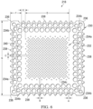
- the diameter of the apertures 234 in the periphery 230 of the base layer 218 may be larger than the diameter of the apertures 234 in the central portion 232 of the base layer 218.
- the diameter of each of the apertures 234 may be between about 1 millimeter to about 50 millimeters. In some embodiments, the diameter of each of the apertures 234 may be between about 1 millimeter to about 20 millimeters.
- the apertures 234 may have a uniform pattern or may be randomly distributed on the base layer 218. The size and configuration of the apertures 234 may be designed to control the adherence of the dressing 110 to the epidermis 204 as described below.
- the apertures 234 positioned in the periphery 230 may be apertures 234a, the apertures 234 positioned at the corners 236 of the periphery 230 may be apertures 234b, and the apertures 234 positioned in the central portion 232 may be apertures 234c.
- the apertures 234a may have a diameter between about 9.8 millimeters to about 10.2 millimeters.
- the apertures 234b may have a diameter between about 7.75 millimeters to about 8.75 millimeters.
- the apertures 234c may have a diameter between about 1.8 millimeters to about 2.2 millimeters.
- the base layer 218 may be a soft, pliable material suitable for providing a fluid seal with the tissue site 202 as described herein.
- the base layer 218 may comprise a silicone gel, a soft silicone, hydrocolloid, hydrogel, polyurethane gel, polyolefin gel, hydrogenated styrenic copolymer gels, a foamed gel, a soft closed cell foam such as polyurethanes and polyolefins coated with an adhesive described below, polyurethane, polyolefin, or hydrogenated styrenic copolymers.
- the base layer 218 may have a thickness between about 500 microns ( ⁇ m) and about 1000 microns ( ⁇ m). In some embodiments, the base layer 218 has a stiffness between about 5 Shore OO and about 80 Shore OO.
- the base layer 218 may be comprised of hydrophobic or hydrophilic materials.
- the base layer 218 may be a hydrophobic-coated material.
- the base layer 218 may be formed by coating a spaced material, such as, for example, woven, nonwoven, molded, or extruded mesh with a hydrophobic material.
- the hydrophobic material for the coating may be a soft silicone, for example.
- the adhesive 226 may extend through openings in the spaced material analogous to the apertures 234 described below.
- At least one of the apertures 234a in the periphery 230 of the base layer 218 may be positioned at the edges 238 of the periphery 230 and may have an interior cut open or exposed at the edges 238 that is in fluid communication in a lateral direction with the edges 238.
- the lateral direction may refer to a direction toward the edges 238 and in the same plane as the base layer 218.
- a plurality of the apertures 234a in the periphery 230 may be positioned proximate to or at the edges 238 and in fluid communication in a lateral direction with the edges 238.
- the adhesive 226 may be a medically-acceptable adhesive.
- the adhesive 226 may also be flowable.
- the adhesive 226 may comprise an acrylic adhesive, rubber adhesive, high-tack silicone adhesive, polyurethane, or other adhesive substance.
- the adhesive 226 may be a pressure-sensitive adhesive comprising an acrylic adhesive with coating weight of 15 grams/m 2 (gsm) to 70 grams/m 2 (gsm).
- the adhesive 226 may be a layer having substantially the same shape as the periphery 230 of the base layer 218 as shown in Figure 5 .
- the layer of the adhesive 226 may be continuous or discontinuous. Discontinuities in the adhesive 226 may be provided by apertures (not shown) in the adhesive 226.
- the apertures in the adhesive 226 may be formed after application of the adhesive 226 or by coating the adhesive 226 in patterns on a carrier layer, such as, for example, a side of the cover 125 adapted to face the epidermis 204. Further, the apertures in the adhesive 226 may be sized to control the amount of the adhesive 226 extending through the apertures 234 in the base layer 218 to reach the epidermis 204. The apertures in the adhesive 226 may also be sized to enhance the Moisture Vapor Transfer Rate (MVTR) of the dressing 110.
- MVTR Moisture Vapor Transfer Rate
- Factors that may be utilized to control the adhesion strength of the dressing 110 may include the diameter and number of the apertures 234 in the base layer 218, the thickness of the base layer 218, the thickness and amount of the adhesive 226, and the tackiness of the adhesive 226.
- An increase in the amount of the adhesive 226 extending through the apertures 234 generally corresponds to an increase in the adhesion strength of the dressing 110.
- a decrease in the thickness of the base layer 218 generally corresponds to an increase in the amount of adhesive 226 extending through the apertures 234.
- the diameter and configuration of the apertures 234, the thickness of the base layer 218, and the amount and tackiness of the adhesive utilized may be varied to provide a desired adhesion strength for the dressing 110.
- the thickness of the base layer 218 may be about 200 microns
- the layer of adhesive 226 may have a thickness of about 30 microns and a tackiness of 2000 grams per 25 centimeter wide strip
- the diameter of the apertures 234a in the base layer 218 may be about 10 millimeters.
- Such a configuration may reduce the occurrence of blistering, erythema, and leakage when in use.
- Such a configuration may provide, for example, increased patient comfort and increased durability of the dressing 110.
- the release liner 242 may be a polyester material such as polyethylene terephthalate (PET), or similar polar semi-crystalline polymer.
- PET polyethylene terephthalate
- the use of a polar semi-crystalline polymer for the release liner 242 may substantially preclude wrinkling or other deformation of the dressing 110.
- the polar semi-crystalline polymer may be highly orientated and resistant to softening, swelling, or other deformation that may occur when brought into contact with components of the dressing 110, or when subjected to temperature or environmental variations, or sterilization.
- a release agent may be disposed on a side of the release liner 242 that is configured to contact the base layer 218.
- the cover 125 may be substantially as described above with reference to Figure 1 .
- the cover 125 may have a margin or a periphery 244 and a central portion 246.
- the cover 125 may also have a first surface 248 and a second surface 250 opposite the first surface 248.
- the cover 125 may additionally include an aperture 252.
- the aperture 252 may be an opening or a hole through the cover 125. In some embodiments, the aperture 252 may be located substantially centered on the cover 125.
- the aperture 252 may be configured to allow fluid communication from the first surface 248 of the cover 125 through the dressing 110.
- the periphery 244 of the cover 125 may be positioned proximate to the periphery 230 of the base layer 218 such that the central portion 246 of the cover 125 and the central portion 232 of the base layer 218 define an enclosure 254.
- the adhesive 226 may be positioned at least between the periphery 244 of the cover 125 and the periphery 230 of the base layer 218.
- the cover 125 may cover the tissue site 202 and the tissue interface 120 to provide a fluid seal and a sealed space 256 between the tissue site 202 and the cover 125 of the dressing 110. Further, the cover 125 may cover other tissue, such as a portion of the epidermis 204, surrounding the tissue site 202 to provide the fluid seal between the cover 125 and the tissue site 202. In some embodiments, a portion of the periphery 244 of the cover 125 may extend beyond the periphery 230 of the base layer 218 and into direct contact with tissue surrounding the tissue site 202.
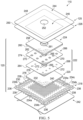
- the absorbent material 224, the isolation layer 222 and the manifold 220 may be disposed within the enclosure 254, the sealed space 256, or both.
- the isolation layer 222 may be positioned between the absorbent material 224 and the manifold 220, the absorbent material 224 may be encapsulated between the cover 125 and the isolation layer 222, and the manifold 220 may be positioned between the isolation layer 222 and the tissue site 202 and the base layer 218, if equipped.
- the absorbent material 224 may be a super absorbent and may have a first surface 258 and a second surface 260 opposite the first surface 258.
- the absorbent material 224 may further include an opening 261 configured to align with the aperture 252 of the cover 125.
- the first surface 258 of the absorbent material 224 may be adjacent to the second surface 250 of the cover 125.
- the absorbent material 224 is isolated from the manifold 220 and the tissue site 202 when negative pressure is being applied to the tissue site 202. When negative pressure is not being applied to the tissue site 202, the absorbent material 224 is in fluid communication with the manifold 220 and the tissue site 202 through the isolation layer 222.
- the absorbent material 224 may be configured to absorb fluid from the tissue site 202 when the absorbent material 224 is in fluid communication with the manifold 220 and the tissue site 202 through the isolation layer 222.
- Materials suitable for the absorbent material may include Luquafleece ® material, Texsus FP2326, BASF 402C, Technical Absorbents 2317 available from Technical Absorbents (www.techabsorbents.com), sodium polyacrylate super absorbers, cellulosics (carboxy methyl cellulose and salts such as sodium CMC), or alginates.
- the isolation layer 222 may be disposed between the absorbent material 224 and the manifold 220.
- the isolation layer 222 may have a first surface 262 and a second surface 264 opposite the first surface 262.
- the first surface 262 of the isolation layer 222 may be adjacent to the second surface 260 of the absorbent material 224.
- the isolation layer 222 may further include an opening 265.
- the opening 265 may be aligned with the opening 261 of the absorbent material 224 but may be smaller than the opening 261 of the absorbent material 224.
- the isolation layer 222 may be configured to restrict fluid flow from the tissue site 202 to the absorbent material 224 when negative pressure is applied to the dressing 110.
- the isolation layer 222 may include a first layer 266 and a second layer 268.
- the first layer 266 may include a plurality of valve flaps 270 and the second layer may include a plurality of holes 272.
- the plurality of holes 272 of the second layer 268 may be aligned with the plurality of valve flaps 270 of the first layer 266.
- the plurality of valve flaps 270 may be configured to be closed when negative pressure is applied to the dressing 110. When closed, the plurality of valve flaps 270 may fluidly seal the plurality of holes 272 of the second layer 268.
- the plurality of valve flaps 270 may be configured to move away from the plurality of holes 272 when negative pressure is not being applied to the dressing 110 to provide a passage 271 through the isolation layer 222.
- the plurality of valve flaps 270 may be configured to permit fluid flow in a first direction from the second surface 264 of the isolation layer 222 towards the first surface 262 of the isolation layer 222 when negative pressure is not being applied to the dressing 110.
- the plurality of valve flaps 270 may prevent fluid flow in a second direction from the first surface 262 of the isolation layer 222 towards the second surface 264 of the isolation layer 222.
- the plurality of valve flaps 270 may prevent fluid flow in all directions, for example, both the first direction and the second direction.
- the isolation layer 222 may be only one layer that may include the plurality of valve flaps 270 that are configured to close when negative pressure is applied to the dressing 110 and are configured to open when negative pressure is not being applied to the dressing to provide a passage through the isolation layer 222.
- the first layer 266 of the isolation layer 222 may have a first surface that may be the first surface 262 of the isolation layer 222.
- the first layer 266 of the isolation layer 222 may have a second surface 274 opposite the first surface 262.
- the plurality of valve flaps 270 may be configured to open from the second surface 274 of the first layer 266 towards the first surface 262 of the isolation layer 222.
- the first layer 266 of the isolation layer 222 may be thick enough to enable the plurality of valve flaps 270 to open and expose the plurality of holes 272 of the second layer 268 without any portion of the plurality of valve flaps 270 coming into contact with the absorbent material 224.
- the plurality of valve flaps 270 of the isolation layer 222 may be check valves in some embodiments.
- Exemplary check valves may include ball check valves, diaphragm check valves, flap-style check valves, swing check valves, stop-check valves, duckbill valves, pneumatic non-return valves, or other one-way valves configured to automatically permit fluid flow in a single direction and to prevent fluid flow in any other direction.
- the at least one spacer or projection may be positioned around or adjacent to one or more of the valve flaps 270 and configured in any suitable manner to provide a pathway or additional space between the isolation layer 222 and the absorbent material 224.
- the pathway may ensure that the plurality of valve flaps 270 have enough space to open to expose the plurality of holes 272 of the second layer 268 of the isolation layer 222 when the negative-pressure source 105 is stopped.
- Both the first layer 266 and the second layer 268 of the isolation layer 222 may be comprised of a liquid impermeable film.
- the first layer 266 and the second layer 268 of the isolation layer 222 may comprise one or more of the following materials: hydrophilic polyurethane; cellulosics; hydrophilic polyamides; polyvinyl alcohol; polyvinyl pyrrolidone; hydrophilic acrylics; hydrophilic silicone elastomers; an INSPIRE 2301 material from Expopack Advanced Coatings of Wrexham, United Kingdom having, for example, an MVTR (inverted cup technique) of 14400 g/m 2 /24 hours and a thickness of about 30 microns; a thin, uncoated polymer drape; natural rubbers; polyisoprene; styrene butadiene rubber; chloroprene rubber; polybutadiene; nitrile rubber; butyl rubber; ethylene propylene rubber; ethylene propylene diene monomer;
- the first layer 266 and the second layer 268 of the isolation layer 222 may be a flexible, breathable film, membrane, or sheet having a high MVTR of, for example, at least about 300g/m 2 per 24 hours. In other embodiments, a low or no vapor transfer drape might be used.
- the first layer 266 and the second layer 268 of the isolation layer 222 may comprise a range of medically suitable films having a thickness between about 15 microns ( ⁇ m) to about 50 microns ( ⁇ m).
- the first layer 266 and the second layer 268 of the isolation layer 222 may be a non-breathable film, membrane, or sheet that may be substantially vapor and liquid impermeable.
- the manifold 220 may have a first surface 276 and a second surface 278 opposite the first surface 276.
- the manifold 220 may comprise or consist essentially of a means for distributing fluid relative to the tissue site 202.
- the manifold 220 may be adapted to receive negative pressure from the negative-pressure source 105 and distribute negative pressure through multiple apertures across or through the manifold 220, which may have the effect of collecting fluid from the tissue site 202 and drawing the fluid toward the negative-pressure source 105.
- the manifold 220 may comprise a plurality of pathways, which can be interconnected to improve distribution or collection of fluids.
- the manifold 220 may comprise or consist essentially of a porous material having interconnected fluid pathways.
- suitable porous material that can be adapted to form interconnected fluid pathways may include cellular foam, including open-cell foam such as reticulated foam; porous tissue collections; and other porous material such as gauze or felted mat that generally include pores, edges, and/or walls. Liquids, gels, and other foams may also include or be cured to include apertures and fluid pathways.
- the manifold 220 may additionally or alternatively comprise projections that form interconnected fluid pathways.
- the manifold 220 may be molded to provide surface projections that define interconnected fluid pathways.
- the manifold 220 may comprise or consist essentially of reticulated foam having pore sizes and free volume that may vary according to needs of a prescribed therapy.
- reticulated foam having a free volume of at least 90% may be suitable for many therapy applications, and foam having an average pore size in a range of 400-600 microns (40-50 pores per inch) may be particularly suitable for some types of therapy.
- the tensile strength of the manifold 220 may also vary according to needs of a prescribed therapy.
- the 25% compression load deflection of the manifold 220 may be at least 0.35 pounds per square inch, and the 65% compression load deflection may be at least 0.43 pounds per square inch.
- the tensile strength of the manifold 220 may be at least 10 pounds per square inch.
- the manifold 220 may have a tear strength of at least 2.5 pounds per inch.
- the manifold 220 may be foam comprised of polyols such as polyester or polyether, isocyanate such as toluene diisocyanate, and polymerization modifiers such as amines and tin compounds.
- the manifold 220 may be reticulated polyurethane foam such as found in GRANUFOAM TM dressing or V.A.C. VERAFLO TM dressing, both available from Kinetic Concepts, Inc. of San Antonio, Texas.
- the thickness of the manifold 220 may also vary according to needs of a prescribed therapy. For example, the thickness of the manifold 220 may be decreased to reduce tension on peripheral tissue of the tissue site 202. The thickness of the manifold 220 can also affect the conformability of the manifold 220. In some embodiments, a thickness in a range of about 5 millimeters to 10 millimeters may be suitable.
- the manifold 220 may be hydrophilic.
- the manifold 220 may also wick fluid away from a tissue site, while continuing to distribute negative pressure to the tissue site 202.
- the wicking properties of the manifold 220 may draw fluid away from the tissue site 202 by capillary flow or other wicking mechanisms.
- An example of a hydrophilic material that may be suitable is a polyvinyl alcohol, open-cell foam such as V.A.C. WHITEFOAM TM dressing available from Kinetic Concepts, Inc. of San Antonio, Texas.
- Other hydrophilic foams may include those made from polyether.
- Other foams that may exhibit hydrophilic characteristics include hydrophobic foams that have been treated or coated to provide hydrophilicity.
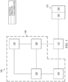
- a conduit interface 279 may be configured to fluidly couple the dressing 110 to the container 115 and the therapy unit 145.
- the conduit interface 279 may include a fluid connection 280 and a negative pressure port 282.
- the negative pressure port 282 may be disposed through the fluid connection 280 and the fluid connection 280 may fluidly isolate the negative pressure port 282 from the absorbent material 224.
- the fluid connection 280 may extend into or be received by a negative pressure passage 281 defined by an alignment of the aperture 252 of the cover 125, the opening 261 of the absorbent material 224, and the opening 265 in the isolation layer 222.
- the fluid connection 280 may have a first surface 284 that may be configured to couple to the first surface 262 of the isolation layer 222.
- the fluid connection 280 may have a second surface 286 opposite the first surface 284.
- the fluid connection 280 may extend through the cover 125, the absorbent material 224, and the isolation layer 222 to couple to the first surface 276 of the manifold 220.
- the negative pressure port 282 may extend through the fluid connection 280 from the second surface 286 to the first surface 284.
- the negative pressure port 282 may have an end 288 that may be configured to deliver negative pressure from the negative-pressure source 105 to the manifold 220.
- the end 288 of the negative pressure port 282 may be proximate to the opening 265 of the isolation layer 222 and below or between the second surface 260 of the absorbent material 224 and the manifold 220 to deliver negative pressure through the opening 265 to the manifold 220.
- the end 288 of the negative pressure port 282 may be fluidly sealed about the opening 265 of the isolation layer 222.
- the negative pressure port 282 may bypass or extend through the absorbent material 224 such that the end 288 is positioned at or between the second surface 260 of the absorbent material 224 and the manifold 220.
- the negative pressure port 282 may couple to a conduit 290 that may couple to the container 115 and the negative-pressure source 105 of the therapy unit 145.
Landscapes
- Health & Medical Sciences (AREA)
- Heart & Thoracic Surgery (AREA)
- General Health & Medical Sciences (AREA)
- Engineering & Computer Science (AREA)
- Biomedical Technology (AREA)
- Life Sciences & Earth Sciences (AREA)
- Animal Behavior & Ethology (AREA)
- Public Health (AREA)
- Veterinary Medicine (AREA)
- Vascular Medicine (AREA)
- Anesthesiology (AREA)
- Hematology (AREA)
- Pulmonology (AREA)
- Media Introduction/Drainage Providing Device (AREA)
Applications Claiming Priority (2)
| Application Number | Priority Date | Filing Date | Title |
|---|---|---|---|
| US202163263617P | 2021-11-05 | 2021-11-05 | |
| PCT/IB2022/059300 WO2023079382A1 (en) | 2021-11-05 | 2022-09-29 | Negative pressure wound therapy dressing with isolated super absorbent |
Publications (2)
| Publication Number | Publication Date |
|---|---|
| EP4426252A1 EP4426252A1 (en) | 2024-09-11 |
| EP4426252B1 true EP4426252B1 (en) | 2025-06-25 |
Family
ID=83898029
Family Applications (1)
| Application Number | Title | Priority Date | Filing Date |
|---|---|---|---|
| EP22790368.9A Active EP4426252B1 (en) | 2021-11-05 | 2022-09-29 | Negative pressure wound therapy dressing with isolated super absorbent |
Country Status (5)
| Country | Link |
|---|---|
| US (1) | US20250134724A1 (enExample) |
| EP (1) | EP4426252B1 (enExample) |
| JP (1) | JP2024540211A (enExample) |
| CN (1) | CN118201575A (enExample) |
| WO (1) | WO2023079382A1 (enExample) |
Families Citing this family (1)
| Publication number | Priority date | Publication date | Assignee | Title |
|---|---|---|---|---|
| WO2026083177A1 (en) * | 2024-10-16 | 2026-04-23 | Solventum Intellectual Properties Company | Dressing and therapy system for exudate management |
Family Cites Families (3)
| Publication number | Priority date | Publication date | Assignee | Title |
|---|---|---|---|---|
| US9981075B2 (en) * | 2011-11-23 | 2018-05-29 | Kci Licensing, Inc. | Reduced pressure tissue treatment systems and methods having a reduced pressure dressing and associated valve |
| TWM506601U (zh) * | 2015-01-08 | 2015-08-11 | Benq Materials Corp | 負壓傷口敷料 |
| CN107929833B (zh) * | 2017-12-28 | 2021-02-19 | 广州润虹医药科技股份有限公司 | 一种防倒流负压引流装置 |
-
2022
- 2022-09-29 CN CN202280073720.3A patent/CN118201575A/zh active Pending
- 2022-09-29 JP JP2024525818A patent/JP2024540211A/ja active Pending
- 2022-09-29 EP EP22790368.9A patent/EP4426252B1/en active Active
- 2022-09-29 WO PCT/IB2022/059300 patent/WO2023079382A1/en not_active Ceased
- 2022-09-29 US US18/706,470 patent/US20250134724A1/en active Pending
Also Published As
| Publication number | Publication date |
|---|---|
| JP2024540211A (ja) | 2024-10-31 |
| EP4426252A1 (en) | 2024-09-11 |
| CN118201575A (zh) | 2024-06-14 |
| WO2023079382A1 (en) | 2023-05-11 |
| US20250134724A1 (en) | 2025-05-01 |
Similar Documents
| Publication | Publication Date | Title |
|---|---|---|
| EP3813750B1 (en) | Release liner with edge protection | |
| US20240325210A1 (en) | High-density evaporative bridge dressing | |
| US11179275B2 (en) | Methods for manufacturing and assembling dual material tissue interface for negative-pressure therapy | |
| EP4124324A1 (en) | Peel and place dressing for thick exudate and instillation | |
| US20180353338A1 (en) | Customizable Composite Dressings For Improved Granulation And Reduced Maceration With Negative-Pressure Treatment | |
| WO2018226667A1 (en) | Customizable composite dressings for improved granulation and reduced maceration negative-pressure treatment | |
| WO2018226707A1 (en) | Composite dressings for improved granulation reduced maceration with negative-pressure treatment | |
| US20220087870A1 (en) | Absorbent Dressing With Indicator And Mechanical Decoupling Of Expansion Forces | |
| EP3634337A1 (en) | Methods for manufacturing and assembling dual material tissue interface for negative-pressure therapy | |
| EP3993747B1 (en) | Customizable dressings for negative-pressure treatment of large areas | |
| US20230390481A1 (en) | Customizable dressing with integrated bridge | |
| US20250049613A1 (en) | Negative pressure wound therapy dressing with a slitted foam layer | |
| EP4426252B1 (en) | Negative pressure wound therapy dressing with isolated super absorbent | |
| EP4031082B1 (en) | Long-term wear tissue interfaces for high-closure force negative- pressure therapy dressings | |
| US20250177633A1 (en) | Negative pressure wound therapy system | |
| US20250186263A1 (en) | Apparatus and system for managing tubing at a tissue site | |
| EP4536163A1 (en) | Negative pressure wound therapy apparatuses and systems |
Legal Events
| Date | Code | Title | Description |
|---|---|---|---|
| STAA | Information on the status of an ep patent application or granted ep patent |
Free format text: STATUS: UNKNOWN |
|
| STAA | Information on the status of an ep patent application or granted ep patent |
Free format text: STATUS: THE INTERNATIONAL PUBLICATION HAS BEEN MADE |
|
| PUAI | Public reference made under article 153(3) epc to a published international application that has entered the european phase |
Free format text: ORIGINAL CODE: 0009012 |
|
| STAA | Information on the status of an ep patent application or granted ep patent |
Free format text: STATUS: REQUEST FOR EXAMINATION WAS MADE |
|
| 17P | Request for examination filed |
Effective date: 20240605 |
|
| AK | Designated contracting states |
Kind code of ref document: A1 Designated state(s): AL AT BE BG CH CY CZ DE DK EE ES FI FR GB GR HR HU IE IS IT LI LT LU LV MC MK MT NL NO PL PT RO RS SE SI SK SM TR |
|
| DAV | Request for validation of the european patent (deleted) | ||
| DAX | Request for extension of the european patent (deleted) | ||
| GRAP | Despatch of communication of intention to grant a patent |
Free format text: ORIGINAL CODE: EPIDOSNIGR1 |
|
| STAA | Information on the status of an ep patent application or granted ep patent |
Free format text: STATUS: GRANT OF PATENT IS INTENDED |
|
| INTG | Intention to grant announced |
Effective date: 20250409 |
|
| GRAS | Grant fee paid |
Free format text: ORIGINAL CODE: EPIDOSNIGR3 |
|
| GRAA | (expected) grant |
Free format text: ORIGINAL CODE: 0009210 |
|
| STAA | Information on the status of an ep patent application or granted ep patent |
Free format text: STATUS: THE PATENT HAS BEEN GRANTED |
|
| AK | Designated contracting states |
Kind code of ref document: B1 Designated state(s): AL AT BE BG CH CY CZ DE DK EE ES FI FR GB GR HR HU IE IS IT LI LT LU LV MC MK MT NL NO PL PT RO RS SE SI SK SM TR |
|
| REG | Reference to a national code |
Ref country code: GB Ref legal event code: FG4D |
|
| REG | Reference to a national code |
Ref country code: CH Ref legal event code: EP |
|
| REG | Reference to a national code |
Ref country code: CH Ref legal event code: EP |
|
| REG | Reference to a national code |
Ref country code: IE Ref legal event code: FG4D |
|
| REG | Reference to a national code |
Ref country code: DE Ref legal event code: R096 Ref document number: 602022016574 Country of ref document: DE |
|
| PG25 | Lapsed in a contracting state [announced via postgrant information from national office to epo] |
Ref country code: FI Free format text: LAPSE BECAUSE OF FAILURE TO SUBMIT A TRANSLATION OF THE DESCRIPTION OR TO PAY THE FEE WITHIN THE PRESCRIBED TIME-LIMIT Effective date: 20250625 |
|
| PGFP | Annual fee paid to national office [announced via postgrant information from national office to epo] |
Ref country code: DE Payment date: 20250820 Year of fee payment: 4 |
|
| REG | Reference to a national code |
Ref country code: LT Ref legal event code: MG9D |
|
| PG25 | Lapsed in a contracting state [announced via postgrant information from national office to epo] |
Ref country code: NO Free format text: LAPSE BECAUSE OF FAILURE TO SUBMIT A TRANSLATION OF THE DESCRIPTION OR TO PAY THE FEE WITHIN THE PRESCRIBED TIME-LIMIT Effective date: 20250925 Ref country code: GR Free format text: LAPSE BECAUSE OF FAILURE TO SUBMIT A TRANSLATION OF THE DESCRIPTION OR TO PAY THE FEE WITHIN THE PRESCRIBED TIME-LIMIT Effective date: 20250926 |
|
| PG25 | Lapsed in a contracting state [announced via postgrant information from national office to epo] |
Ref country code: BG Free format text: LAPSE BECAUSE OF FAILURE TO SUBMIT A TRANSLATION OF THE DESCRIPTION OR TO PAY THE FEE WITHIN THE PRESCRIBED TIME-LIMIT Effective date: 20250625 |
|
| PG25 | Lapsed in a contracting state [announced via postgrant information from national office to epo] |
Ref country code: HR Free format text: LAPSE BECAUSE OF FAILURE TO SUBMIT A TRANSLATION OF THE DESCRIPTION OR TO PAY THE FEE WITHIN THE PRESCRIBED TIME-LIMIT Effective date: 20250625 |
|
| PGFP | Annual fee paid to national office [announced via postgrant information from national office to epo] |
Ref country code: AT Payment date: 20251020 Year of fee payment: 4 |
|
| PG25 | Lapsed in a contracting state [announced via postgrant information from national office to epo] |
Ref country code: RS Free format text: LAPSE BECAUSE OF FAILURE TO SUBMIT A TRANSLATION OF THE DESCRIPTION OR TO PAY THE FEE WITHIN THE PRESCRIBED TIME-LIMIT Effective date: 20250925 |
|
| PG25 | Lapsed in a contracting state [announced via postgrant information from national office to epo] |
Ref country code: LV Free format text: LAPSE BECAUSE OF FAILURE TO SUBMIT A TRANSLATION OF THE DESCRIPTION OR TO PAY THE FEE WITHIN THE PRESCRIBED TIME-LIMIT Effective date: 20250625 |
|
| REG | Reference to a national code |
Ref country code: NL Ref legal event code: MP Effective date: 20250625 |
|
| PG25 | Lapsed in a contracting state [announced via postgrant information from national office to epo] |
Ref country code: NL Free format text: LAPSE BECAUSE OF FAILURE TO SUBMIT A TRANSLATION OF THE DESCRIPTION OR TO PAY THE FEE WITHIN THE PRESCRIBED TIME-LIMIT Effective date: 20250625 |
|
| PG25 | Lapsed in a contracting state [announced via postgrant information from national office to epo] |
Ref country code: PT Free format text: LAPSE BECAUSE OF FAILURE TO SUBMIT A TRANSLATION OF THE DESCRIPTION OR TO PAY THE FEE WITHIN THE PRESCRIBED TIME-LIMIT Effective date: 20251027 |
|
| REG | Reference to a national code |
Ref country code: AT Ref legal event code: MK05 Ref document number: 1805707 Country of ref document: AT Kind code of ref document: T Effective date: 20250625 |
|
| PG25 | Lapsed in a contracting state [announced via postgrant information from national office to epo] |
Ref country code: IS Free format text: LAPSE BECAUSE OF FAILURE TO SUBMIT A TRANSLATION OF THE DESCRIPTION OR TO PAY THE FEE WITHIN THE PRESCRIBED TIME-LIMIT Effective date: 20251025 |
|
| PG25 | Lapsed in a contracting state [announced via postgrant information from national office to epo] |
Ref country code: AT Free format text: LAPSE BECAUSE OF FAILURE TO SUBMIT A TRANSLATION OF THE DESCRIPTION OR TO PAY THE FEE WITHIN THE PRESCRIBED TIME-LIMIT Effective date: 20250625 Ref country code: SM Free format text: LAPSE BECAUSE OF FAILURE TO SUBMIT A TRANSLATION OF THE DESCRIPTION OR TO PAY THE FEE WITHIN THE PRESCRIBED TIME-LIMIT Effective date: 20250625 |
|
| PG25 | Lapsed in a contracting state [announced via postgrant information from national office to epo] |
Ref country code: CZ Free format text: LAPSE BECAUSE OF FAILURE TO SUBMIT A TRANSLATION OF THE DESCRIPTION OR TO PAY THE FEE WITHIN THE PRESCRIBED TIME-LIMIT Effective date: 20250625 |
|
| PG25 | Lapsed in a contracting state [announced via postgrant information from national office to epo] |
Ref country code: PL Free format text: LAPSE BECAUSE OF FAILURE TO SUBMIT A TRANSLATION OF THE DESCRIPTION OR TO PAY THE FEE WITHIN THE PRESCRIBED TIME-LIMIT Effective date: 20250625 |
|
| PG25 | Lapsed in a contracting state [announced via postgrant information from national office to epo] |
Ref country code: EE Free format text: LAPSE BECAUSE OF FAILURE TO SUBMIT A TRANSLATION OF THE DESCRIPTION OR TO PAY THE FEE WITHIN THE PRESCRIBED TIME-LIMIT Effective date: 20250625 |
|
| PG25 | Lapsed in a contracting state [announced via postgrant information from national office to epo] |
Ref country code: SK Free format text: LAPSE BECAUSE OF FAILURE TO SUBMIT A TRANSLATION OF THE DESCRIPTION OR TO PAY THE FEE WITHIN THE PRESCRIBED TIME-LIMIT Effective date: 20250625 |
|
| PG25 | Lapsed in a contracting state [announced via postgrant information from national office to epo] |
Ref country code: ES Free format text: LAPSE BECAUSE OF FAILURE TO SUBMIT A TRANSLATION OF THE DESCRIPTION OR TO PAY THE FEE WITHIN THE PRESCRIBED TIME-LIMIT Effective date: 20250625 |
|
| PG25 | Lapsed in a contracting state [announced via postgrant information from national office to epo] |
Ref country code: RO Free format text: LAPSE BECAUSE OF FAILURE TO SUBMIT A TRANSLATION OF THE DESCRIPTION OR TO PAY THE FEE WITHIN THE PRESCRIBED TIME-LIMIT Effective date: 20250625 |
|
| PG25 | Lapsed in a contracting state [announced via postgrant information from national office to epo] |
Ref country code: DK Free format text: LAPSE BECAUSE OF FAILURE TO SUBMIT A TRANSLATION OF THE DESCRIPTION OR TO PAY THE FEE WITHIN THE PRESCRIBED TIME-LIMIT Effective date: 20250625 |
|
| PG25 | Lapsed in a contracting state [announced via postgrant information from national office to epo] |
Ref country code: IT Free format text: LAPSE BECAUSE OF FAILURE TO SUBMIT A TRANSLATION OF THE DESCRIPTION OR TO PAY THE FEE WITHIN THE PRESCRIBED TIME-LIMIT Effective date: 20250625 |
|
| PLBE | No opposition filed within time limit |
Free format text: ORIGINAL CODE: 0009261 |
|
| STAA | Information on the status of an ep patent application or granted ep patent |
Free format text: STATUS: NO OPPOSITION FILED WITHIN TIME LIMIT |