EP4425949A1 - Information processing device and control method thereof for displaying and recording the image - Google Patents
Information processing device and control method thereof for displaying and recording the image Download PDFInfo
- Publication number
- EP4425949A1 EP4425949A1 EP24159907.5A EP24159907A EP4425949A1 EP 4425949 A1 EP4425949 A1 EP 4425949A1 EP 24159907 A EP24159907 A EP 24159907A EP 4425949 A1 EP4425949 A1 EP 4425949A1
- Authority
- EP
- European Patent Office
- Prior art keywords
- setting
- dynamic range
- display
- image
- processing device
- Prior art date
- Legal status (The legal status is an assumption and is not a legal conclusion. Google has not performed a legal analysis and makes no representation as to the accuracy of the status listed.)
- Pending
Links
Images




Classifications
-
- H—ELECTRICITY
- H04—ELECTRIC COMMUNICATION TECHNIQUE
- H04N—PICTORIAL COMMUNICATION, e.g. TELEVISION
- H04N23/00—Cameras or camera modules comprising electronic image sensors; Control thereof
- H04N23/80—Camera processing pipelines; Components thereof
- H04N23/84—Camera processing pipelines; Components thereof for processing colour signals
-
- H—ELECTRICITY
- H04—ELECTRIC COMMUNICATION TECHNIQUE
- H04N—PICTORIAL COMMUNICATION, e.g. TELEVISION
- H04N23/00—Cameras or camera modules comprising electronic image sensors; Control thereof
- H04N23/60—Control of cameras or camera modules
- H04N23/66—Remote control of cameras or camera parts, e.g. by remote control devices
- H04N23/663—Remote control of cameras or camera parts, e.g. by remote control devices for controlling interchangeable camera parts based on electronic image sensor signals
-
- H—ELECTRICITY
- H04—ELECTRIC COMMUNICATION TECHNIQUE
- H04N—PICTORIAL COMMUNICATION, e.g. TELEVISION
- H04N25/00—Circuitry of solid-state image sensors [SSIS]; Control thereof
- H04N25/50—Control of the SSIS exposure
- H04N25/53—Control of the integration time
- H04N25/532—Control of the integration time by controlling global shutters in CMOS SSIS
-
- G—PHYSICS
- G06—COMPUTING OR CALCULATING; COUNTING
- G06T—IMAGE DATA PROCESSING OR GENERATION, IN GENERAL
- G06T5/00—Image enhancement or restoration
- G06T5/90—Dynamic range modification of images or parts thereof
-
- H—ELECTRICITY
- H04—ELECTRIC COMMUNICATION TECHNIQUE
- H04N—PICTORIAL COMMUNICATION, e.g. TELEVISION
- H04N23/00—Cameras or camera modules comprising electronic image sensors; Control thereof
- H04N23/60—Control of cameras or camera modules
- H04N23/62—Control of parameters via user interfaces
-
- H—ELECTRICITY
- H04—ELECTRIC COMMUNICATION TECHNIQUE
- H04N—PICTORIAL COMMUNICATION, e.g. TELEVISION
- H04N23/00—Cameras or camera modules comprising electronic image sensors; Control thereof
- H04N23/60—Control of cameras or camera modules
- H04N23/63—Control of cameras or camera modules by using electronic viewfinders
- H04N23/631—Graphical user interfaces [GUI] specially adapted for controlling image capture or setting capture parameters
-
- H—ELECTRICITY
- H04—ELECTRIC COMMUNICATION TECHNIQUE
- H04N—PICTORIAL COMMUNICATION, e.g. TELEVISION
- H04N23/00—Cameras or camera modules comprising electronic image sensors; Control thereof
- H04N23/70—Circuitry for compensating brightness variation in the scene
- H04N23/741—Circuitry for compensating brightness variation in the scene by increasing the dynamic range of the image compared to the dynamic range of the electronic image sensors
-
- H—ELECTRICITY
- H04—ELECTRIC COMMUNICATION TECHNIQUE
- H04N—PICTORIAL COMMUNICATION, e.g. TELEVISION
- H04N23/00—Cameras or camera modules comprising electronic image sensors; Control thereof
- H04N23/80—Camera processing pipelines; Components thereof
- H04N23/82—Camera processing pipelines; Components thereof for controlling camera response irrespective of the scene brightness, e.g. gamma correction
-
- H—ELECTRICITY
- H04—ELECTRIC COMMUNICATION TECHNIQUE
- H04N—PICTORIAL COMMUNICATION, e.g. TELEVISION
- H04N25/00—Circuitry of solid-state image sensors [SSIS]; Control thereof
- H04N25/50—Control of the SSIS exposure
- H04N25/57—Control of the dynamic range
-
- H—ELECTRICITY
- H04—ELECTRIC COMMUNICATION TECHNIQUE
- H04N—PICTORIAL COMMUNICATION, e.g. TELEVISION
- H04N5/00—Details of television systems
- H04N5/76—Television signal recording
- H04N5/907—Television signal recording using static stores, e.g. storage tubes or semiconductor memories
-
- H—ELECTRICITY
- H04—ELECTRIC COMMUNICATION TECHNIQUE
- H04N—PICTORIAL COMMUNICATION, e.g. TELEVISION
- H04N19/00—Methods or arrangements for coding, decoding, compressing or decompressing digital video signals
- H04N19/46—Embedding additional information in the video signal during the compression process
-
- H—ELECTRICITY
- H04—ELECTRIC COMMUNICATION TECHNIQUE
- H04N—PICTORIAL COMMUNICATION, e.g. TELEVISION
- H04N23/00—Cameras or camera modules comprising electronic image sensors; Control thereof
- H04N23/60—Control of cameras or camera modules
- H04N23/667—Camera operation mode switching, e.g. between still and video, sport and normal or high- and low-resolution modes
-
- H—ELECTRICITY
- H04—ELECTRIC COMMUNICATION TECHNIQUE
- H04N—PICTORIAL COMMUNICATION, e.g. TELEVISION
- H04N5/00—Details of television systems
- H04N5/14—Picture signal circuitry for video frequency region
- H04N5/20—Circuitry for controlling amplitude response
-
- H—ELECTRICITY
- H04—ELECTRIC COMMUNICATION TECHNIQUE
- H04N—PICTORIAL COMMUNICATION, e.g. TELEVISION
- H04N9/00—Details of colour television systems
- H04N9/79—Processing of colour television signals in connection with recording
- H04N9/80—Transformation of the television signal for recording, e.g. modulation, frequency changing; Inverse transformation for playback
- H04N9/82—Transformation of the television signal for recording, e.g. modulation, frequency changing; Inverse transformation for playback the individual colour picture signal components being recorded simultaneously only
- H04N9/8205—Transformation of the television signal for recording, e.g. modulation, frequency changing; Inverse transformation for playback the individual colour picture signal components being recorded simultaneously only involving the multiplexing of an additional signal and the colour video signal
Definitions
- the present invention relates to an information processing device and a control method thereof and, in particular, to photographing of HDR images.
- Recent imaging devices are capable of photographing HDR images.
- HDR is an abbreviation for a high dynamic range, and shows a dynamic range wider than a standard dynamic range (SDR).
- SDR standard dynamic range
- the present invention provides a technique to prevent trouble that a user recognizes an image of HDR as an image of another dynamic range and becomes unable to perform confirmation.
- the present invention in its first aspect provides an information processing device as specified in claims 1 to 9.
- the present invention in its second aspect provides a control method as specified in claim 11.
- the present invention in its third aspect provides a control method as specified in claim 12.
- the present invention in its fourth aspect provides a program as specified in claim 13.
- the present invention in its fifth aspect provides a computer readable medium as specified in claim 14.
- FIG. 1 is a cross-sectional diagram showing an arrangement example of main constituting elements (for example, optical members and sensors) of a digital camera (hereinafter, a camera) according to the present embodiment.
- the camera is a lens-interchangeable digital single lens reflex camera, and has a camera body 1 and an interchangeable lens 2.
- an imaging element 10 is, for example, a CMOS image sensor or a CCD image sensor, and a plurality of pixels (storage-type photoelectric conversion elements) are arrayed in the imaging element 10.
- a mechanical shutter 11 provided near the front of the imaging element 10 controls an exposure timing and an exposure time of the imaging element 10.
- a semi-transmissive main mirror 3 and a first reflection mirror 7 arranged on the rear surface of the main mirror 3 jump up at the time of photographing.
- a second reflection mirror 8 reflects a light flux reflected by the first reflection mirror 7 toward a focus detection sensor (AF sensor) 9.
- the AF sensor 9 is, for example, an imaging element having a smaller number of pixels than that of the imaging element 10.
- the first reflection mirror 7, the second reflection mirror 8, and the AF sensor 9 are constituting elements used to perform focus detection at an arbitrary position within an imaging range by a phase difference detection system.
- a photometric sensor (AE sensor) 6 receives an object image (an optical image indicating an object) reflected by a pentaprism 4 and a third reflection mirror 5.
- the AE sensor 6 is capable of outputting brightness information on an object for each of a plurality of regions of a light-receiving unit. The number of the regions is not particularly limited.
- the AE sensor 6 is, for example, an imaging element having a smaller number of pixels than that of the imaging element 10.
- the various imaging elements have, other than pixels arranged in their light-receiving units, an amplification circuit for a pixel signal and a peripheral circuit for signal processing.
- a finder optical system is configured by the pentaprism 4. Although not shown in FIG. 1 , an object image reflected by the pentaprism 4 is observable from an eyepiece. A part of a light beam outside an optical axis among those reflected by the main mirror 3 and diffused by a focusing plate 12 is incident on the AE sensor 6.
- the interchangeable lens 2 communicates with the camera body 1 as occasion demands via a contact of a lens mount unit provided in the camera body 1. Note that exposure control or focus adjustment control is performed using information on a captured image since the main mirror 3 and the first reflection mirror 7 jump up at the time of displaying a live view and recording a moving image.
- FIG. 2 is a block diagram showing a configuration example of an electric circuit of the camera (the camera body 1 and the interchangeable lens 2) shown in FIG. 1 .
- a control unit 21 is a one-chip microcomputer in which an arithmetic and logic unit (ALU), a ROM, a RAM, an A/D converter, a timer, and a serial communication port (SPI) are, for example, embedded.
- the control unit 21 controls operations of the camera body 1 and the interchangeable lens 2 by, for example, loading a program stored in the ROM into the RAM and running the loaded program. A specific operation of the control unit 21 will be described later.
- a signal processing circuit 25 controls the imaging element 10 according to instructions from the control unit 21, and applies A/D conversion and signal processing to a signal output from the imaging element 10 to obtain an image signal. Further, the signal processing circuit 25 performs required image processing such as compression and synthesis when recording an obtained image signal.
- a memory 28 is, for example, a DRAM, and used as a work memory when the signal processing circuit 25 performs various signal processing or used as a VRAM when an image is displayed on a display 27 that will be described later.
- the display 27 is a display unit such as a rear liquid-crystal display of the camera body 1 and an external display, and displays various information and images such as camera setting values, messages, a menu screen, and captured images.
- the display 27 enables HDR display (display in an HDR mode).
- HDR is an abbreviation for a high dynamic range, and shows a dynamic range wider than a standard dynamic range (SDR).
- SDR standard dynamic range
- the display 27 is controlled according to instructions from the control unit 21.
- a storage unit 26 is, for example, a semiconductor memory card, and an image signal of a captured image is input from the signal processing circuit 25 to the storage unit 26.
- a motor 22 controls up/down movement of the main mirror 3 and the first reflection mirror 7 according to instructions from the control unit 21.
- An operation unit 23 is an input-device group used by a user to operate the camera.
- the operation unit 23 includes, for example, a release switch used to provide instructions to perform a photographing standby operation or instructions to perform photographing operations (performing photographing of a still image and starting photographing of a moving image), a photographing-mode selection switch used to select a photographing mode, a direction key, and a determination key.
- a contact unit 29 is a contact used to communicate with the interchangeable lens 2, and an input/output signal line of a serial communication port of the control unit 21 is connected to the contact unit 29.
- a shutter driving unit 24 drives the mechanical shutter 11 (controls an opening/closing operation of the mechanical shutter 11) according to instructions from the control unit 21.
- the interchangeable lens 2 is provided with a contact unit 50 that corresponds to the contact unit 29.
- the contact unit 50 is connected to a lens control unit 51 that is a one-chip microcomputer similar to that of the control unit 21, and communication with the lens control unit 51 is possible via the contact unit 50.
- the lens control unit 51 has, for example, a microprocessor, a ROM, and a RAM, and controls the operation of the interchangeable lens 2 on the basis of instructions from the control unit 21 by loading a program stored in the ROM into the RAM and running the loaded program. Further, the lens control unit 51 notifies the control unit 21 of various information such as a state of the interchangeable lens 2.
- a focus-lens driving unit 52 is connected to an output terminal of the lens control unit 51, and drives a focus lens.
- a zoom driving unit 53 changes an angle of view of the interchangeable lens 2 according to instructions from the lens control unit 51.
- An aperture driving unit 54 adjusts an aperture amount of an aperture according to instructions from the lens control unit 51.
- the data communication between the lens control unit 51 and the control unit 21 (data communication via the contact units 29 and 50) is enabled. Further, power (for example, power used to drive a motor and an actuator) is supplied from the camera body 1 to the interchangeable lens 2 via the contact units 29 and 50.
- information required by the control unit 21 to perform focus detection and exposure computation (for example, optical information inherent in the interchangeable lens 2 and an object distance based on a distance encoder) is, for example, output from the lens control unit 51 to the control unit 21. Further, results (focus adjustment information and aperture information) of focus detection and exposure computation performed by the control unit 21 are output from the control unit 21 to the lens control unit 51.
- the lens control unit 51 controls a position of the focus lens according to focus adjustment information, and controls an aperture amount of an aperture according to aperture information.
- a photographing operation operation from photographing to recording
- the control unit 21 becomes operatable and performs initialization processing.
- the control unit 21 performs communication with the lens control unit 51 to obtain various lens information for focus detection and photometry.
- the control unit 21 performs various settings (for example, the setting of an arbitrary photographing mode) according to an operation by the user on the operation unit 23.
- the control unit 21 When a shutter switch included in the operation unit 23 is pressed half, the control unit 21 performs a photographing standby operation including automatic focus (AF) processing and automatic exposure (AE) processing. Subsequently, the control unit 21 performs the photographing operation when the shutter switch is pressed full.
- AF automatic focus
- AE automatic exposure
- FIG. 3 is a block diagram showing an example of a function configuration relating to the photographing operation
- FIG. 4 is a flowchart showing an example of the photographing operation.
- respective units are function units corresponding to processing performed by the control unit 21.
- at least one function unit may be realized by a hardware circuit.
- RAW image data 301 image data of a RAW image obtained by imaging is configured by a plurality of pixel data.
- Each of the plurality of pixel data configuring the RAW image data 301 indicates the strength of a color of a color filter provided in a corresponding pixel (photoelectric conversion element), and does not have information on other colors.
- the respective pixels of an imaging element are provided with any of red (R), green (G), and blue (B) color filters.
- the control unit 21 acquires setting information on an opto-electronic transfer function (OETF).
- OETF opto-electronic transfer function
- a user is enabled to specify an OETF using the operation unit 23.
- the control unit 21 performs a setting relating to the specified OETF.
- information on a specified (set) OETF is acquired.
- the user is enabled to specify an OETF of hybrid log gamma (HLG) defined in ITU-R recommendation BT.2100 as an OETF corresponding to HDR.
- HLG hybrid log gamma
- the user is enabled to specify an OETF corresponding to ITU-R recommendation BT.709 as an OETF corresponding to SDR.
- OETF As an OETF corresponding to HDR, inverse characteristics of an electro-optical transfer function (EOTF) of perceptual quantization (PQ) defined in ITU-R recommendation BT.2100 may be specified.
- the setting, specification, and information of an OETF may be interpreted as the setting, specification, and information of a color gamut corresponding to the OETF.
- An opto-optical transfer function (OOTF) may be used in combination with an OETF. For example, when a dynamic range of a recorded image (developed image that will be described later) depends on a photographing mode, a change in the dynamic range corresponding to a change in the photographing mode may be realized by an OOTF.
- the control unit 21 acquires setting information on an EOTF.
- the user is enabled to specify an EOTF using the operation unit 23.
- the control unit 21 performs a setting relating to the specified EOTF.
- information on a set (specified) EOTF is acquired.
- the user is enabled to specify inverse characteristics of an OETF of HLG as an EOTF corresponding to HDR, and specify an EOTF corresponding to ITU-R recommendation BT.709 as an EOTF corresponding to SDR.
- an EOTF of PQ may be specified.
- the EOTF corresponding to the setting information acquired in S402 is the same as or different from the inverse characteristics of the OETF corresponding to the setting information acquired in S401 depending on cases.
- information on the specific OETF for example, inverse characteristics of the set OETF
- the setting, specification, and information of an EOTF may be interpreted as the setting, specification, and information of a color gamut corresponding to the EOTF.
- control unit 21 generates a developed image by applying development processing to a RAW image according to the setting information (the setting of the OETF) acquired in S401.
- the development processing includes, for example, processing from the processing of a white balance unit 302 to the processing of a color-brightness adjustment unit 306 in FIG. 3 .
- the white balance unit 302 performs white balance processing to correct color fogging caused by a light source to reproduce white. For example, the white balance unit 302 plots respective pixel data (data of a red (R) component, data of a green (G) component, or data of a blue (B) component) configuring the RAW image data 301 into a prescribed color space such as an xy color space. The white balance unit 302 calculates integrated values (an integrated value of the R component, an integrated value of the G component, and an integrated value of the B component) of the pixel data plotted near a black-body radiation locus corresponding to a light-source color in the prescribed color space.
- integrated values an integrated value of the R component, an integrated value of the G component, and an integrated value of the B component
- the white balance unit 302 calculates a white balance coefficient of the R component and a white balance coefficient of the B component from the calculated integrated values.
- the white balance unit 302 performs white balance processing by applying the calculated white balance coefficients to the RAW image data 301.
- a color interpolation unit 303 performs noise reduction processing and color interpolation processing on the RAW image data after the white balance processing.
- color image data in which the respective pixel data include all color information on the R component, the G component, and the B component is generated.
- the color image data generated by the color interpolation unit 303 is converted into basic color image data by the processing of a matrix conversion unit 304 and a gamma conversion unit 305.
- the gamma conversion unit 305 performs gradation conversion (gamma conversion) using the OETF corresponding to the setting information acquired in S401.
- the color-brightness adjustment unit 306 performs processing to improve the appearance of an image on a color image obtained by the gamma conversion unit 305.
- the color-brightness adjustment unit 306 performs image correction such as detecting an evening scene and emphasizing chroma.
- the control unit 21 compresses the developed image (high-resolution image) generated in S403 in a prescribed format such as HEVC. Then, the control unit 21 (recording control unit 308) records the developed image after the compression and meta information (meta data) corresponding to the setting information (the setting of the EOTF) acquired in S402 on the storage unit 26 (storage medium) in association with each other. For example, in a case where the setting information (the setting of the OETF) acquired in S401 corresponds to HDR and the setting information (the setting of the EOTF) acquired in S402 corresponds to SDR, the developed image and meta data corresponding to SDR are recorded on the storage unit 26 in association with each other. In the first embodiment, the recording control unit 308 outputs an image file 309 including the developed image and the meta data. The output image file 309 is stored in the storage unit 26. Note that the file of the developed image and the file of the meta data may be separately created.
- FIG. 5 shows an example of the structure of an image file.
- An image file 501 has ftype 502 in the first place, and then has moov 503, Etc 505, and mdat 506 in the second, third, and fourth places, respectively.
- the ftype 502 is a box in which a file type is stored (described).
- the moov 503 is a box in which meta data is stored.
- the mdat 506 is a box in which media data (image data) is stored.
- the Etc 505 is a box in which other data is stored.
- the moov 503 has, as a child element, trak 504 that is a box in which meta data relating to an image is stored.
- the image file may have, as a container format (image file format), a high-efficiency image file (HEIF) format defined in ISO/IEC 23008-12.
- the image file may have, as a container format (image file format), an MP4 format defined in ISO/IEC 14496-15.
- the image file may have other container formats (image file formats).
- the storage unit 26 may be removed from the camera (camera body 1) and attached to a reproduction device not shown.
- the reproduction device is enabled to reproduce an image file recorded on the storage unit 26 in S404 of FIG. 4 .
- the reproduction device automatically performs gradation conversion when meta data corresponding to HDR is contained in an image file and SDR display (display in an SDR mode) is performed.
- the gradation conversion performed by the reproduction device is, for example, processing to convert an HDR image (an image of a high dynamic range) into an SDR image (an image of a standard dynamic range).
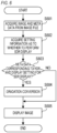
- FIG. 6 is a flowchart showing an example of a reproduction operation in the reproduction device.
- the reproduction device acquires an image and meta data from an image file.
- the reproduction device acquires setting information as to whether to perform SDR display.
- the reproduction device determines whether a condition that the meta data acquired in S601 corresponds to HDR and that the setting information acquired in S602 corresponds to SDR (a display setting to perform SDR display has been made) is satisfied. The processing proceeds to S604 when the condition is satisfied. Otherwise, the processing proceeds to S605.
- the reproduction device performs gradation conversion to convert an HDR image (an image of HDR) into an SDR image (an image of SDR) on the image acquired in S601.
- the conversion properties of the gradation conversion are determined on the basis of the meta data (for example, an EOTF) acquired in S601.
- the reproduction device displays an image.
- an image after the gradation conversion of S604 is displayed.
- the image acquired in S601 (the image before the gradation conversion of S604) is displayed.
- the reproduction device performs SDR display or HDR display as image display according to a display setting.
- setting information as to whether to perform SDR display is acquired in S602
- setting information on a display color gamut may be acquired in S602.
- a determination may be made as to whether a color gamut corresponding to meta data acquired in S601 matches a color gamut corresponding to setting information acquired in S602.
- the processing may proceed to S604 when the color gamut corresponding to the meta data does not match the color gamut corresponding to the setting information. Otherwise, the processing may proceed to S605.
- gradation conversion to obtain an image of the color gamut corresponding to the setting information acquired in S602 may be performed on an image acquired in S601.
- FIG. 6 may be performed as processing to display an image on the display 27 by the camera.
- meta information on a recorded image meta information corresponding to a dynamic range different from a dynamic range of the image in the first embodiment.
- a user recognizes an image (video) of HDR as an image (video) of another dynamic range (for example, SDR) and becomes unable to perform confirmation and compilation is prevented.
- SDR another dynamic range
- automatic gradation conversion is prevented so that the user recognizes an HDR image as an SDR image and is enabled to perform confirmation and compilation.
- FIG. 7 is a block diagram showing an example of a function configuration relating to the display operation
- FIG. 8 is a flowchart showing an example of the display operation.
- a display 27 corresponds to SDR, and is unable to perform HDR display but able to perform only SDR display.
- RAW image data 701 to a color-brightness adjustment unit 706 are the same as the RAW image data 301 to the color-brightness adjustment unit 306 shown in FIG. 3 .
- the processing of S801 to S803 is the same as the processing of S401 to S403 shown in FIG. 4 .
- a control unit 21 acquires setting information on a display setting.
- the display setting is a setting as to whether to perform gradation conversion
- the gradation conversion is processing to convert an HDR image into an SDR image.
- a display setting to perform the gradation conversion may be interpreted as a display setting corresponding to HDR
- a display setting not to perform the gradation conversion may be interpreted as a display setting corresponding to SDR.
- a user is enabled to specify the validity or invalidity of the gradation conversion using an operation unit 23, and the control unit 21 sets the validity or invalidity of the gradation conversion according to user's specification.
- control unit 21 determines whether a condition that setting information (the setting of an EOTF) acquired in S802 corresponds to HDR and that setting information acquired in S804 corresponds to HDR is satisfied. The processing proceeds to S806 when the condition is satisfied. Otherwise, the processing proceeds to S807.
- control unit 21 (a gradation conversion unit 707) performs gradation conversion on a developed image generated in S803.
- the gradation conversion is, for example, processing to convert an HDR image into an SDR image.
- the conversion properties of the gradation conversion are determined on the basis of the setting information (the setting of the EOTF) acquired in S802.
- the control unit 21 displays an image on the display 27.
- an image after the gradation conversion of S806 is displayed.
- the image acquired in S803 an image before the gradation conversion of S806 is displayed.
- the setting information (the setting of the EOTF) acquired in S802 corresponds to SDR
- the gradation conversion of S806 is not performed and the image generated in S803 is displayed even where the display setting to perform the gradation conversion in S806 has been made. That is, the image is displayed with a display setting corresponding to SDR (a display setting not to perform the gradation conversion in S806).
- a user is enabled to recognize an image (video) of HDR as an image (video) of another dynamic range (for example, SDR) and photograph the HDR image while confirming the same.
- Embodiment(s) of the present invention can also be realized by a computer of a system or apparatus that reads out and executes computer executable instructions (e.g., one or more programs) recorded on a storage medium (which may also be referred to more fully as a 'non-transitory computer-readable storage medium') to perform the functions of one or more of the above-described embodiment(s) and/or that includes one or more circuits (e.g., application specific integrated circuit (ASIC)) for performing the functions of one or more of the above-described embodiment(s), and by a method performed by the computer of the system or apparatus by, for example, reading out and executing the computer executable instructions from the storage medium to perform the functions of one or more of the above-described embodiment(s) and/or controlling the one or more circuits to perform the functions of one or more of the above-described embodiment(s).
- computer executable instructions e.g., one or more programs
- a storage medium which may also be referred to more fully as
- the computer may comprise one or more processors (e.g., central processing unit (CPU), micro processing unit (MPU)) and may include a network of separate computers or separate processors to read out and execute the computer executable instructions.
- the computer executable instructions may be provided to the computer, for example, from a network or the storage medium.
- the storage medium may include, for example, one or more of a hard disk, a random-access memory (RAM), a read only memory (ROM), a storage of distributed computing systems, an optical disk (such as a compact disc (CD), digital versatile disc (DVD), or Blu-ray Disc (BD) TM ), a flash memory device, a memory card, and the like.
- An information processing device performs a first setting relating to an opto-electronic transfer function (OETF), performs a second setting relating to an electro-optical transfer function (EOTF), generates a developed image by applying development processing to a RAW image according to the first setting, and performs control to record the developed image on a storage medium.
- OETF opto-electronic transfer function
- EOTF electro-optical transfer function
- control is performed to record the developed image and meta information corresponding to the second setting on the storage medium in association with each other.
Landscapes
- Engineering & Computer Science (AREA)
- Multimedia (AREA)
- Signal Processing (AREA)
- Human Computer Interaction (AREA)
- Physics & Mathematics (AREA)
- General Physics & Mathematics (AREA)
- Theoretical Computer Science (AREA)
- Studio Devices (AREA)
- Image Processing (AREA)
Abstract
An information processing device according to the present invention performs a first setting relating to an opto-electronic transfer function (OETF), performs a second setting relating to an electro-optical transfer function (EOTF), generates a developed image by applying development processing to a RAW image according to the first setting, and performs control to record the developed image on a storage medium. In a case where the first setting is a setting corresponding to a high dynamic range and the second setting is a setting corresponding to a dynamic range different from the high dynamic range, control is performed to record the developed image and meta information corresponding to the second setting on the storage medium in association with each other.
Description
- The present invention relates to an information processing device and a control method thereof and, in particular, to photographing of HDR images.
- Recent imaging devices (for example, digital cameras) are capable of photographing HDR images. HDR is an abbreviation for a high dynamic range, and shows a dynamic range wider than a standard dynamic range (SDR).
- It is disclosed in
Japanese Patent Application Laid-open No. 2018-7194 - There is a case that a user photographs an HDR image and then confirms and compiles the HDR image while recognizing the same as an SDR image (as it is) without performing gradation conversion. However, even if the user wants to confirm and compile the HDR image while recognizing the same as the SDR image, there is a possibility that gradation conversion to convert the HDR image into the SDR image (narrow a dynamic range from HDR to SDR) is automatically performed, whereby the user becomes unable to perform desired confirmation and compilation.
- The present invention provides a technique to prevent trouble that a user recognizes an image of HDR as an image of another dynamic range and becomes unable to perform confirmation.
- The present invention in its first aspect provides an information processing device as specified in
claims 1 to 9. - The present invention in its second aspect provides a control method as specified in
claim 11. - The present invention in its third aspect provides a control method as specified in
claim 12. - The present invention in its fourth aspect provides a program as specified in claim 13.
- The present invention in its fifth aspect provides a computer readable medium as specified in claim 14.
- Further features of the present invention will become apparent from the following description of exemplary embodiments with reference to the attached drawings.
-
-
FIG. 1 is a cross-sectional diagram of a camera; -
FIG. 2 is a block diagram of the camera; -
FIG. 3 is a block diagram of a function configuration relating to a photographing operation according to a first embodiment; -
FIG. 4 is a flowchart of the photographing operation according to the first embodiment; -
FIG. 5 is a schematic diagram of an image file according to the first embodiment; -
FIG. 6 is a flowchart of a reproduction operation; -
FIG. 7 is a block diagram of a function configuration relating to a display operation according to a second embodiment; and -
FIG. 8 is a flowchart of the display operation according to the second embodiment. - Hereinafter, embodiments of the present invention will be described in detail with reference to the accompanying drawings. Note that the following embodiments do not intend to limit the present invention according to claims. In the following embodiments, a plurality of features will be described. However, the plurality of features are not necessarily essential for the present invention and may be arbitrarily combined together. In addition, the same or similar configurations will be denoted by the same reference symbols, and their duplicated descriptions will be omitted. Further, an example in which the present invention is applied to a digital camera will be described in the following embodiments. However, information processing devices to which the present invention is applicable are not limited to digital cameras. For example, the present invention is applicable to various imaging devices (for example, smart phones and tablet terminals). The present invention is also applicable to information processing devices such as smartphones, tablets, and personal computers (PCs) connected to imaging devices (or capable of communicating with the imaging devices).
-
FIG. 1 is a cross-sectional diagram showing an arrangement example of main constituting elements (for example, optical members and sensors) of a digital camera (hereinafter, a camera) according to the present embodiment. InFIG. 1 , the camera is a lens-interchangeable digital single lens reflex camera, and has acamera body 1 and aninterchangeable lens 2. In thecamera body 1, animaging element 10 is, for example, a CMOS image sensor or a CCD image sensor, and a plurality of pixels (storage-type photoelectric conversion elements) are arrayed in theimaging element 10. Amechanical shutter 11 provided near the front of theimaging element 10 controls an exposure timing and an exposure time of theimaging element 10. - A semi-transmissive
main mirror 3 and a first reflection mirror 7 arranged on the rear surface of themain mirror 3 jump up at the time of photographing. Asecond reflection mirror 8 reflects a light flux reflected by the first reflection mirror 7 toward a focus detection sensor (AF sensor) 9. TheAF sensor 9 is, for example, an imaging element having a smaller number of pixels than that of theimaging element 10. The first reflection mirror 7, thesecond reflection mirror 8, and theAF sensor 9 are constituting elements used to perform focus detection at an arbitrary position within an imaging range by a phase difference detection system. - A photometric sensor (AE sensor) 6 receives an object image (an optical image indicating an object) reflected by a
pentaprism 4 and athird reflection mirror 5. TheAE sensor 6 is capable of outputting brightness information on an object for each of a plurality of regions of a light-receiving unit. The number of the regions is not particularly limited. TheAE sensor 6 is, for example, an imaging element having a smaller number of pixels than that of theimaging element 10. The various imaging elements have, other than pixels arranged in their light-receiving units, an amplification circuit for a pixel signal and a peripheral circuit for signal processing. - A finder optical system is configured by the
pentaprism 4. Although not shown inFIG. 1 , an object image reflected by thepentaprism 4 is observable from an eyepiece. A part of a light beam outside an optical axis among those reflected by themain mirror 3 and diffused by a focusingplate 12 is incident on theAE sensor 6. Theinterchangeable lens 2 communicates with thecamera body 1 as occasion demands via a contact of a lens mount unit provided in thecamera body 1. Note that exposure control or focus adjustment control is performed using information on a captured image since themain mirror 3 and the first reflection mirror 7 jump up at the time of displaying a live view and recording a moving image. -
FIG. 2 is a block diagram showing a configuration example of an electric circuit of the camera (thecamera body 1 and the interchangeable lens 2) shown inFIG. 1 . In thecamera body 1, acontrol unit 21 is a one-chip microcomputer in which an arithmetic and logic unit (ALU), a ROM, a RAM, an A/D converter, a timer, and a serial communication port (SPI) are, for example, embedded. Thecontrol unit 21 controls operations of thecamera body 1 and theinterchangeable lens 2 by, for example, loading a program stored in the ROM into the RAM and running the loaded program. A specific operation of thecontrol unit 21 will be described later. - Signals output from the
AF sensor 9 and theAE sensor 6 are connected to an input terminal of the A/D converter of thecontrol unit 21. Asignal processing circuit 25 controls theimaging element 10 according to instructions from thecontrol unit 21, and applies A/D conversion and signal processing to a signal output from theimaging element 10 to obtain an image signal. Further, thesignal processing circuit 25 performs required image processing such as compression and synthesis when recording an obtained image signal. Amemory 28 is, for example, a DRAM, and used as a work memory when thesignal processing circuit 25 performs various signal processing or used as a VRAM when an image is displayed on adisplay 27 that will be described later. Thedisplay 27 is a display unit such as a rear liquid-crystal display of thecamera body 1 and an external display, and displays various information and images such as camera setting values, messages, a menu screen, and captured images. Thedisplay 27 enables HDR display (display in an HDR mode). HDR is an abbreviation for a high dynamic range, and shows a dynamic range wider than a standard dynamic range (SDR). Thedisplay 27 is controlled according to instructions from thecontrol unit 21. Astorage unit 26 is, for example, a semiconductor memory card, and an image signal of a captured image is input from thesignal processing circuit 25 to thestorage unit 26. - A
motor 22 controls up/down movement of themain mirror 3 and the first reflection mirror 7 according to instructions from thecontrol unit 21. Anoperation unit 23 is an input-device group used by a user to operate the camera. Theoperation unit 23 includes, for example, a release switch used to provide instructions to perform a photographing standby operation or instructions to perform photographing operations (performing photographing of a still image and starting photographing of a moving image), a photographing-mode selection switch used to select a photographing mode, a direction key, and a determination key. Acontact unit 29 is a contact used to communicate with theinterchangeable lens 2, and an input/output signal line of a serial communication port of thecontrol unit 21 is connected to thecontact unit 29. Ashutter driving unit 24 drives the mechanical shutter 11 (controls an opening/closing operation of the mechanical shutter 11) according to instructions from thecontrol unit 21. - The
interchangeable lens 2 is provided with acontact unit 50 that corresponds to thecontact unit 29. Thecontact unit 50 is connected to alens control unit 51 that is a one-chip microcomputer similar to that of thecontrol unit 21, and communication with thelens control unit 51 is possible via thecontact unit 50. Thelens control unit 51 has, for example, a microprocessor, a ROM, and a RAM, and controls the operation of theinterchangeable lens 2 on the basis of instructions from thecontrol unit 21 by loading a program stored in the ROM into the RAM and running the loaded program. Further, thelens control unit 51 notifies thecontrol unit 21 of various information such as a state of theinterchangeable lens 2. A focus-lens driving unit 52 is connected to an output terminal of thelens control unit 51, and drives a focus lens. Azoom driving unit 53 changes an angle of view of theinterchangeable lens 2 according to instructions from thelens control unit 51. Anaperture driving unit 54 adjusts an aperture amount of an aperture according to instructions from thelens control unit 51. - When the
interchangeable lens 2 is attached to thecamera body 1, the data communication between thelens control unit 51 and the control unit 21 (data communication via thecontact units 29 and 50) is enabled. Further, power (for example, power used to drive a motor and an actuator) is supplied from thecamera body 1 to theinterchangeable lens 2 via thecontact units control unit 21 to perform focus detection and exposure computation (for example, optical information inherent in theinterchangeable lens 2 and an object distance based on a distance encoder) is, for example, output from thelens control unit 51 to thecontrol unit 21. Further, results (focus adjustment information and aperture information) of focus detection and exposure computation performed by thecontrol unit 21 are output from thecontrol unit 21 to thelens control unit 51. Thelens control unit 51 controls a position of the focus lens according to focus adjustment information, and controls an aperture amount of an aperture according to aperture information. - Hereinafter, a first embodiment of the present invention will be described. In the first embodiment, a photographing operation (operation from photographing to recording) of the camera will be described. For example, when a power switch included in the
operation unit 23 shown inFIG. 2 is operated by a user and power of the camera (camera body 1) is turned on, thecontrol unit 21 becomes operatable and performs initialization processing. In the initialization processing, thecontrol unit 21 performs communication with thelens control unit 51 to obtain various lens information for focus detection and photometry. Thecontrol unit 21 performs various settings (for example, the setting of an arbitrary photographing mode) according to an operation by the user on theoperation unit 23. When a shutter switch included in theoperation unit 23 is pressed half, thecontrol unit 21 performs a photographing standby operation including automatic focus (AF) processing and automatic exposure (AE) processing. Subsequently, thecontrol unit 21 performs the photographing operation when the shutter switch is pressed full. - The photographing operation will be described with reference to
FIGS. 3 and4 .FIG. 3 is a block diagram showing an example of a function configuration relating to the photographing operation, andFIG. 4 is a flowchart showing an example of the photographing operation. InFIG. 3 , respective units are function units corresponding to processing performed by thecontrol unit 21. However, at least one function unit may be realized by a hardware circuit. RAW image data 301 (image data of a RAW image) obtained by imaging is configured by a plurality of pixel data. Each of the plurality of pixel data configuring theRAW image data 301 indicates the strength of a color of a color filter provided in a corresponding pixel (photoelectric conversion element), and does not have information on other colors. Here, the respective pixels of an imaging element are provided with any of red (R), green (G), and blue (B) color filters. - In S401 of
FIG. 4 , thecontrol unit 21 acquires setting information on an opto-electronic transfer function (OETF). In the first embodiment, a user is enabled to specify an OETF using theoperation unit 23. When the OETF is specified by the user, thecontrol unit 21 performs a setting relating to the specified OETF. In S401, information on a specified (set) OETF is acquired. For example, the user is enabled to specify an OETF of hybrid log gamma (HLG) defined in ITU-R recommendation BT.2100 as an OETF corresponding to HDR. Further, the user is enabled to specify an OETF corresponding to ITU-R recommendation BT.709 as an OETF corresponding to SDR. As an OETF corresponding to HDR, inverse characteristics of an electro-optical transfer function (EOTF) of perceptual quantization (PQ) defined in ITU-R recommendation BT.2100 may be specified. The setting, specification, and information of an OETF may be interpreted as the setting, specification, and information of a color gamut corresponding to the OETF. An opto-optical transfer function (OOTF) may be used in combination with an OETF. For example, when a dynamic range of a recorded image (developed image that will be described later) depends on a photographing mode, a change in the dynamic range corresponding to a change in the photographing mode may be realized by an OOTF. - In S402, the
control unit 21 acquires setting information on an EOTF. In the first embodiment, the user is enabled to specify an EOTF using theoperation unit 23. When the EOTF is specified by the user, thecontrol unit 21 performs a setting relating to the specified EOTF. In S402, information on a set (specified) EOTF is acquired. For example, the user is enabled to specify inverse characteristics of an OETF of HLG as an EOTF corresponding to HDR, and specify an EOTF corresponding to ITU-R recommendation BT.709 as an EOTF corresponding to SDR. As an EOTF corresponding to HDR, an EOTF of PQ may be specified. The EOTF corresponding to the setting information acquired in S402 is the same as or different from the inverse characteristics of the OETF corresponding to the setting information acquired in S401 depending on cases. When setting information on a specific OETF is acquired in S401, information on the specific OETF (for example, inverse characteristics of the set OETF) may be acquired as setting information on an OETF regardless of the setting (specification) of an EOTF. The setting, specification, and information of an EOTF may be interpreted as the setting, specification, and information of a color gamut corresponding to the EOTF. - In S403, the
control unit 21 generates a developed image by applying development processing to a RAW image according to the setting information (the setting of the OETF) acquired in S401. The development processing includes, for example, processing from the processing of awhite balance unit 302 to the processing of a color-brightness adjustment unit 306 inFIG. 3 . - The
white balance unit 302 performs white balance processing to correct color fogging caused by a light source to reproduce white. For example, thewhite balance unit 302 plots respective pixel data (data of a red (R) component, data of a green (G) component, or data of a blue (B) component) configuring theRAW image data 301 into a prescribed color space such as an xy color space. Thewhite balance unit 302 calculates integrated values (an integrated value of the R component, an integrated value of the G component, and an integrated value of the B component) of the pixel data plotted near a black-body radiation locus corresponding to a light-source color in the prescribed color space. Then, thewhite balance unit 302 calculates a white balance coefficient of the R component and a white balance coefficient of the B component from the calculated integrated values. Thewhite balance unit 302 performs white balance processing by applying the calculated white balance coefficients to theRAW image data 301. - A
color interpolation unit 303 performs noise reduction processing and color interpolation processing on the RAW image data after the white balance processing. Thus, color image data in which the respective pixel data include all color information on the R component, the G component, and the B component is generated. - The color image data generated by the
color interpolation unit 303 is converted into basic color image data by the processing of amatrix conversion unit 304 and agamma conversion unit 305. Here, thegamma conversion unit 305 performs gradation conversion (gamma conversion) using the OETF corresponding to the setting information acquired in S401. - Then, the color-
brightness adjustment unit 306 performs processing to improve the appearance of an image on a color image obtained by thegamma conversion unit 305. For example, the color-brightness adjustment unit 306 performs image correction such as detecting an evening scene and emphasizing chroma. - In S404, the control unit 21 (compression unit 307) compresses the developed image (high-resolution image) generated in S403 in a prescribed format such as HEVC. Then, the control unit 21 (recording control unit 308) records the developed image after the compression and meta information (meta data) corresponding to the setting information (the setting of the EOTF) acquired in S402 on the storage unit 26 (storage medium) in association with each other. For example, in a case where the setting information (the setting of the OETF) acquired in S401 corresponds to HDR and the setting information (the setting of the EOTF) acquired in S402 corresponds to SDR, the developed image and meta data corresponding to SDR are recorded on the
storage unit 26 in association with each other. In the first embodiment, therecording control unit 308 outputs animage file 309 including the developed image and the meta data. Theoutput image file 309 is stored in thestorage unit 26. Note that the file of the developed image and the file of the meta data may be separately created. -
FIG. 5 shows an example of the structure of an image file. Animage file 501 has ftype 502 in the first place, and then hasmoov 503,Etc 505, and mdat 506 in the second, third, and fourth places, respectively. Theftype 502 is a box in which a file type is stored (described). Themoov 503 is a box in which meta data is stored. Themdat 506 is a box in which media data (image data) is stored. TheEtc 505 is a box in which other data is stored. Themoov 503 has, as a child element, trak 504 that is a box in which meta data relating to an image is stored. In S404, information showing at least one of the EOTF and the color gamut corresponding to the setting information acquired in S402 is stored in thetrak 504 as meta data corresponding to the setting information (the setting of the EOTF) acquired in S402. Note that the setting information (the setting of the EOTF) acquired in S402 may be stored in other specific regions. The image file may have, as a container format (image file format), a high-efficiency image file (HEIF) format defined in ISO/IEC 23008-12. The image file may have, as a container format (image file format), an MP4 format defined in ISO/IEC 14496-15. The image file may have other container formats (image file formats). - The
storage unit 26 may be removed from the camera (camera body 1) and attached to a reproduction device not shown. The reproduction device is enabled to reproduce an image file recorded on thestorage unit 26 in S404 ofFIG. 4 . The reproduction device automatically performs gradation conversion when meta data corresponding to HDR is contained in an image file and SDR display (display in an SDR mode) is performed. The gradation conversion performed by the reproduction device is, for example, processing to convert an HDR image (an image of a high dynamic range) into an SDR image (an image of a standard dynamic range).FIG. 6 is a flowchart showing an example of a reproduction operation in the reproduction device. - In S601, the reproduction device acquires an image and meta data from an image file.
- In S602, the reproduction device acquires setting information as to whether to perform SDR display.
- In S603, the reproduction device determines whether a condition that the meta data acquired in S601 corresponds to HDR and that the setting information acquired in S602 corresponds to SDR (a display setting to perform SDR display has been made) is satisfied. The processing proceeds to S604 when the condition is satisfied. Otherwise, the processing proceeds to S605.
- In S604, the reproduction device performs gradation conversion to convert an HDR image (an image of HDR) into an SDR image (an image of SDR) on the image acquired in S601. The conversion properties of the gradation conversion are determined on the basis of the meta data (for example, an EOTF) acquired in S601.
- In S605, the reproduction device displays an image. When the processing of S604 is performed, an image after the gradation conversion of S604 is displayed. When the processing of S604 is not performed, the image acquired in S601 (the image before the gradation conversion of S604) is displayed. The reproduction device performs SDR display or HDR display as image display according to a display setting.
- In a case where the user photographs an HDR image and wants to confirm and compile the HDR image while recognizing the same as an SDR image (as it is) without performing gradation conversion, he/she specifies an OETF corresponding to HDR (S401 of
FIG. 4 ) and then specifies an EOTF corresponding to SDR (S402). Therefore, meta data corresponding to SDR is stored in an image file (S404). As a result, the processing of S604 is not performed, and the user is enabled to perform desired confirmation and compilation. - Note that an example in which setting information as to whether to perform SDR display is acquired in S602 is described above, but setting information on a display color gamut may be acquired in S602. In S603, a determination may be made as to whether a color gamut corresponding to meta data acquired in S601 matches a color gamut corresponding to setting information acquired in S602. The processing may proceed to S604 when the color gamut corresponding to the meta data does not match the color gamut corresponding to the setting information. Otherwise, the processing may proceed to S605. Then, in S604, gradation conversion to obtain an image of the color gamut corresponding to the setting information acquired in S602 may be performed on an image acquired in S601. Further, an example in which the display device separate from the camera displays an image is described above, but the processing of
FIG. 6 may be performed as processing to display an image on thedisplay 27 by the camera. - As described above, it is possible to record, as meta information on a recorded image, meta information corresponding to a dynamic range different from a dynamic range of the image in the first embodiment. Thus, trouble that a user recognizes an image (video) of HDR as an image (video) of another dynamic range (for example, SDR) and becomes unable to perform confirmation and compilation is prevented. For example, automatic gradation conversion is prevented so that the user recognizes an HDR image as an SDR image and is enabled to perform confirmation and compilation.
- Hereinafter, a second embodiment of the present invention will be described. In the second embodiment, a display operation (an operation from imaging to display, an operation of live-view display) of a camera will be described with reference to
FIGS. 7 and8 .FIG. 7 is a block diagram showing an example of a function configuration relating to the display operation, andFIG. 8 is a flowchart showing an example of the display operation. Note that adisplay 27 corresponds to SDR, and is unable to perform HDR display but able to perform only SDR display. - In
FIG. 7 ,RAW image data 701 to a color-brightness adjustment unit 706 are the same as theRAW image data 301 to the color-brightness adjustment unit 306 shown inFIG. 3 . Further, inFIG. 8 , the processing of S801 to S803 is the same as the processing of S401 to S403 shown inFIG. 4 . - In S804, a
control unit 21 acquires setting information on a display setting. For example, the display setting is a setting as to whether to perform gradation conversion, and the gradation conversion is processing to convert an HDR image into an SDR image. In this case, a display setting to perform the gradation conversion may be interpreted as a display setting corresponding to HDR, and a display setting not to perform the gradation conversion may be interpreted as a display setting corresponding to SDR. For example, a user is enabled to specify the validity or invalidity of the gradation conversion using anoperation unit 23, and thecontrol unit 21 sets the validity or invalidity of the gradation conversion according to user's specification. - In S805, the
control unit 21 determines whether a condition that setting information (the setting of an EOTF) acquired in S802 corresponds to HDR and that setting information acquired in S804 corresponds to HDR is satisfied. The processing proceeds to S806 when the condition is satisfied. Otherwise, the processing proceeds to S807. - In S806, the control unit 21 (a gradation conversion unit 707) performs gradation conversion on a developed image generated in S803. As described above, the gradation conversion is, for example, processing to convert an HDR image into an SDR image. The conversion properties of the gradation conversion are determined on the basis of the setting information (the setting of the EOTF) acquired in S802.
- In S807, the control unit 21 (a display control unit 708) displays an image on the
display 27. When the processing of S806 is performed, an image after the gradation conversion of S806 is displayed. When the processing of S806 is not performed, the image acquired in S803 (an image before the gradation conversion of S806) is displayed. For example, when the setting information (the setting of the EOTF) acquired in S802 corresponds to SDR, the gradation conversion of S806 is not performed and the image generated in S803 is displayed even where the display setting to perform the gradation conversion in S806 has been made. That is, the image is displayed with a display setting corresponding to SDR (a display setting not to perform the gradation conversion in S806). - In a case where the user photographs an HDR image and wants to confirm and compile the HDR image while recognizing the same as an SDR image (as it is) without performing gradation conversion, he/she specifies an OETF corresponding to HDR (S801) and then specifies an EOTF corresponding to SDR (S802). Therefore, an image generated in S803 (an image before the gradation conversion of S806) is displayed on the
display 27. Thus, the user is enabled to recognize an HDR image as an SDR image and photograph the HDR image while confirming the same. - As described above, it is possible to display a captured image with a display setting corresponding to a dynamic range different from a dynamic range of the captured image (a developed image generated in S803) in the second embodiment. Thus, a user is enabled to recognize an image (video) of HDR as an image (video) of another dynamic range (for example, SDR) and photograph the HDR image while confirming the same.
- According to the present invention, trouble that a user recognizes an image of HDR as an image of another dynamic range and becomes unable to perform confirmation is prevented.
- Embodiment(s) of the present invention can also be realized by a computer of a system or apparatus that reads out and executes computer executable instructions (e.g., one or more programs) recorded on a storage medium (which may also be referred to more fully as a 'non-transitory computer-readable storage medium') to perform the functions of one or more of the above-described embodiment(s) and/or that includes one or more circuits (e.g., application specific integrated circuit (ASIC)) for performing the functions of one or more of the above-described embodiment(s), and by a method performed by the computer of the system or apparatus by, for example, reading out and executing the computer executable instructions from the storage medium to perform the functions of one or more of the above-described embodiment(s) and/or controlling the one or more circuits to perform the functions of one or more of the above-described embodiment(s). The computer may comprise one or more processors (e.g., central processing unit (CPU), micro processing unit (MPU)) and may include a network of separate computers or separate processors to read out and execute the computer executable instructions. The computer executable instructions may be provided to the computer, for example, from a network or the storage medium. The storage medium may include, for example, one or more of a hard disk, a random-access memory (RAM), a read only memory (ROM), a storage of distributed computing systems, an optical disk (such as a compact disc (CD), digital versatile disc (DVD), or Blu-ray Disc (BD)™), a flash memory device, a memory card, and the like.
- While the present invention has been described with reference to exemplary embodiments, it is to be understood that the invention is not limited to the disclosed exemplary embodiments. The scope of the following claims is to be accorded the broadest interpretation so as to encompass all such modifications and equivalent structures and functions.
An information processing device according to the present invention performs a first setting relating to an opto-electronic transfer function (OETF), performs a second setting relating to an electro-optical transfer function (EOTF), generates a developed image by applying development processing to a RAW image according to the first setting, and performs control to record the developed image on a storage medium. In a case where the first setting is a setting corresponding to a high dynamic range and the second setting is a setting corresponding to a dynamic range different from the high dynamic range, control is performed to record the developed image and meta information corresponding to the second setting on the storage medium in association with each other.
Claims (14)
- An information processing device comprising:first setting means configured to perform a first setting relating to an opto-electronic transfer function (OETF);second setting means configured to perform a second setting relating to an electro-optical transfer function (EOTF);development means configured to generate a developed image by applying development processing to a RAW image according to the first setting; andrecording control means configured to perform control to record the developed image on a storage medium, whereinin a case where the first setting is a setting corresponding to a high dynamic range and the second setting is a setting corresponding to a dynamic range different from the high dynamic range, the recording control means performs control to record the developed image and meta information corresponding to the second setting on the storage medium in association with each other.
- The information processing device according to claim 1, wherein
the meta information shows at least one of an EOTF and a color gamut corresponding to the second setting. - The information processing device according to claim 1 or 2, further comprising:display control means configured to perform control to display the developed image on display means, wherein,in a case where the first setting is a setting corresponding to a high dynamic range and the second setting is a setting corresponding to a dynamic range different from the high dynamic range, the display control means performs control to display the developed image on the display means with a display setting corresponding to the second setting.
- An information processing device comprising:first setting means configured to perform a first setting relating to an opto-electronic transfer function (OETF);second setting means configured to perform a second setting relating to an electro-optical transfer function (EOTF);development means configured to generate a developed image by applying development processing to a RAW image according to the first setting; anddisplay control means configured to perform control to display the developed image on display means, whereinin a case where the first setting is a setting corresponding to a high dynamic range and the second setting is a setting corresponding to a dynamic range different from the high dynamic range, the display control means performs control to display the developed image on the display means with a display setting corresponding to the second setting.
- The information processing device according to claim 3 or 4, wherein
the display setting is a setting as to whether to perform gradation conversion. - The information processing device according to claim 5, wherein,
in a case where the first setting is a setting corresponding to a high dynamic range and the second setting is a setting corresponding to a dynamic range different from the high dynamic range, the display control means performs control to display the developed image on the display means without performing the gradation conversion. - The information processing device according to claim 5 or 6, wherein
the gradation conversion is processing to convert an image of a high dynamic range into an image of a standard dynamic range. - The information processing device according to any one of claims 1 to 7, wherein
the first setting corresponding to the high dynamic range is a setting corresponding to an OETF of hybrid log gamma (HLG) defined in ITU-R recommendation BT.2100. - The information processing device according to any one of claims 1 to 8, wherein
the development processing includes gradation conversion corresponding to the first setting. - The information processing device according to any one of claims 1 to 9, wherein
the dynamic range different from the high dynamic range is a standard dynamic range. - A control method of an information processing device, comprising:performing a first setting relating to an opto-electronic transfer function (OETF);performing a second setting relating to an electro-optical transfer function (EOTF);generating a developed image by applying development processing to a RAW image according to the first setting; andrecording the developed image on a storage medium, whereinin a case where the first setting is a setting corresponding to a high dynamic range and the second setting is a setting corresponding to a dynamic range different from the high dynamic range, control is performed to record the developed image and meta information corresponding to the second setting on the storage medium in association with each other.
- A control method of an information processing device, comprising:performing a first setting relating to an opto-electronic transfer function (OETF);performing a second setting relating to an electro-optical transfer function (EOTF);generating a developed image by applying development processing to a RAW image according to the first setting; andperforming control to display the developed image on display means, whereinin a case where the first setting is a setting corresponding to a high dynamic range and the second setting is a setting corresponding to a dynamic range different from the high dynamic range, control is performed to display the developed image on the display means with a display setting corresponding to the second setting.
- A program that causes a computer to function as each means of the information processing device according to any one of claims 1 to 10.
- A computer readable medium storing a program that causes a computer to function as each means of the information processing device according to any one of claims 1 to 10.
Applications Claiming Priority (1)
| Application Number | Priority Date | Filing Date | Title |
|---|---|---|---|
| JP2023029426A JP2024122091A (en) | 2023-02-28 | 2023-02-28 | Information processing device and control method thereof |
Publications (1)
| Publication Number | Publication Date |
|---|---|
| EP4425949A1 true EP4425949A1 (en) | 2024-09-04 |
Family
ID=90097590
Family Applications (1)
| Application Number | Title | Priority Date | Filing Date |
|---|---|---|---|
| EP24159907.5A Pending EP4425949A1 (en) | 2023-02-28 | 2024-02-27 | Information processing device and control method thereof for displaying and recording the image |
Country Status (4)
| Country | Link |
|---|---|
| US (1) | US12568316B2 (en) |
| EP (1) | EP4425949A1 (en) |
| JP (1) | JP2024122091A (en) |
| CN (1) | CN118574025A (en) |
Families Citing this family (7)
| Publication number | Priority date | Publication date | Assignee | Title |
|---|---|---|---|---|
| JP2021186435A (en) * | 2020-06-03 | 2021-12-13 | 株式会社三洋物産 | Game machine |
| JP2021186439A (en) * | 2020-06-03 | 2021-12-13 | 株式会社三洋物産 | Pachinko machine |
| JP2021186437A (en) * | 2020-06-03 | 2021-12-13 | 株式会社三洋物産 | Pachinko machine |
| JP2021186433A (en) * | 2020-06-03 | 2021-12-13 | 株式会社三洋物産 | Pachinko machine |
| JP2021186438A (en) * | 2020-06-03 | 2021-12-13 | 株式会社三洋物産 | Pachinko machine |
| JP2021186436A (en) * | 2020-06-03 | 2021-12-13 | 株式会社三洋物産 | Game machine |
| JP2021186434A (en) * | 2020-06-03 | 2021-12-13 | 株式会社三洋物産 | Game machine |
Citations (3)
| Publication number | Priority date | Publication date | Assignee | Title |
|---|---|---|---|---|
| JP2018007194A (en) | 2016-07-08 | 2018-01-11 | 三菱電機株式会社 | Video recording device and video reproducing device |
| EP3163890B1 (en) * | 2014-06-26 | 2020-08-05 | Panasonic Intellectual Property Management Co., Ltd. | Data output device, data output method, and data generation method |
| US20210250518A1 (en) * | 2020-02-06 | 2021-08-12 | Canon Kabushiki Kaisha | Display control apparatus, display control method, and a non-transitory computer-readable medium |
Family Cites Families (8)
| Publication number | Priority date | Publication date | Assignee | Title |
|---|---|---|---|---|
| KR102360613B1 (en) * | 2014-11-07 | 2022-02-09 | 소니그룹주식회사 | Transmission device, transmission method, reception device, and reception method |
| WO2016163603A1 (en) * | 2015-04-05 | 2016-10-13 | 엘지전자 주식회사 | Method and device for transmitting and receiving broadcast signal for broadcast service on basis of xml subtitle |
| TWI650998B (en) * | 2017-12-15 | 2019-02-11 | Mstar Semiconductor, Inc. | Format conversion circuit and related method applied to set-top box |
| WO2019142836A1 (en) * | 2018-01-16 | 2019-07-25 | 株式会社ニコン | Coding device, decoding device, coding method, decoding method, coding program, and decoding program |
| JP7263053B2 (en) * | 2019-02-28 | 2023-04-24 | キヤノン株式会社 | IMAGING DEVICE, IMAGE PROCESSING DEVICE, CONTROL METHOD THEREOF, AND PROGRAM |
| WO2022015540A1 (en) * | 2020-07-17 | 2022-01-20 | Dolby Laboratories Licensing Corporation | Video content creation tool and method |
| JP7693411B2 (en) * | 2020-07-30 | 2025-06-17 | キヤノン株式会社 | IMAGE PROCESSING APPARATUS, IMAGE PROCESSING METHOD, PROGRAM, AND STORAGE MEDIUM |
| US20240013356A1 (en) * | 2022-07-07 | 2024-01-11 | Sonic Star Global Limited | Method for generating high dynamic range image, and image processing system |
-
2023
- 2023-02-28 JP JP2023029426A patent/JP2024122091A/en active Pending
-
2024
- 2024-02-26 US US18/586,865 patent/US12568316B2/en active Active
- 2024-02-27 CN CN202410215419.2A patent/CN118574025A/en active Pending
- 2024-02-27 EP EP24159907.5A patent/EP4425949A1/en active Pending
Patent Citations (3)
| Publication number | Priority date | Publication date | Assignee | Title |
|---|---|---|---|---|
| EP3163890B1 (en) * | 2014-06-26 | 2020-08-05 | Panasonic Intellectual Property Management Co., Ltd. | Data output device, data output method, and data generation method |
| JP2018007194A (en) | 2016-07-08 | 2018-01-11 | 三菱電機株式会社 | Video recording device and video reproducing device |
| US20210250518A1 (en) * | 2020-02-06 | 2021-08-12 | Canon Kabushiki Kaisha | Display control apparatus, display control method, and a non-transitory computer-readable medium |
Non-Patent Citations (1)
| Title |
|---|
| "Study Group Report High-Dynamic-Range (HDR) Imaging Ecosystem", 19 September 2015 (2015-09-19), XP055250336, Retrieved from the Internet <URL:https://www.smpte.org/sites/default/files/Study Group On High-Dynamic-Range-HDR-Ecosystem.pdf> [retrieved on 20160216] * |
Also Published As
| Publication number | Publication date |
|---|---|
| US12568316B2 (en) | 2026-03-03 |
| CN118574025A (en) | 2024-08-30 |
| US20240292113A1 (en) | 2024-08-29 |
| JP2024122091A (en) | 2024-09-09 |
Similar Documents
| Publication | Publication Date | Title |
|---|---|---|
| EP4425949A1 (en) | Information processing device and control method thereof for displaying and recording the image | |
| US8988585B2 (en) | Focus adjustment apparatus | |
| JP7157714B2 (en) | Image processing device and its control method | |
| US11196938B2 (en) | Image processing apparatus and control method for same | |
| JP7371197B2 (en) | Image processing device and its control method | |
| US20170134665A1 (en) | Imaging device | |
| JP5967865B2 (en) | IMAGING DEVICE, IMAGING DEVICE CONTROL METHOD, AND PROGRAM | |
| CN104205797A (en) | Imaging device | |
| JP5923759B2 (en) | Imaging device | |
| US9445000B2 (en) | Communication apparatus, control method therefor, and program | |
| JP7397640B2 (en) | Image processing device and image processing method | |
| US8041206B2 (en) | Imaging apparatus and method for controlling flash emission | |
| JP2004096328A (en) | Electronic camera | |
| JP2012029055A (en) | Imaging device, control method of the same, program, and storage medium | |
| JP5470873B2 (en) | camera | |
| US8902124B2 (en) | Digital image signal processing apparatus for displaying different images respectively on display units and method of controlling the same | |
| JP5414411B2 (en) | Imaging apparatus and control method thereof | |
| JP5414412B2 (en) | Imaging apparatus and control method thereof | |
| JP5311993B2 (en) | Imaging device provided with external display device | |
| WO2022044380A1 (en) | Image capture device, image capture method, and image capture program | |
| JP6486127B2 (en) | Electronic device, control method and program | |
| JP2010278758A (en) | Imaging device | |
| JP2012154694A (en) | Imaging device | |
| JPH10191363A (en) | Imaging device | |
| JP2007202175A (en) | Interchangeable lens electronic camera, interchangeable lens unit and camera body |
Legal Events
| Date | Code | Title | Description |
|---|---|---|---|
| PUAI | Public reference made under article 153(3) epc to a published international application that has entered the european phase |
Free format text: ORIGINAL CODE: 0009012 |
|
| STAA | Information on the status of an ep patent application or granted ep patent |
Free format text: STATUS: THE APPLICATION HAS BEEN PUBLISHED |
|
| AK | Designated contracting states |
Kind code of ref document: A1 Designated state(s): AL AT BE BG CH CY CZ DE DK EE ES FI FR GB GR HR HU IE IS IT LI LT LU LV MC ME MK MT NL NO PL PT RO RS SE SI SK SM TR |
|
| STAA | Information on the status of an ep patent application or granted ep patent |
Free format text: STATUS: REQUEST FOR EXAMINATION WAS MADE |
|
| 17P | Request for examination filed |
Effective date: 20250304 |