EP4425871A1 - Verfahren und vorrichtung zur deterministischen fluss-übergreifenden übertragung sowie elektronische vorrichtung - Google Patents
Verfahren und vorrichtung zur deterministischen fluss-übergreifenden übertragung sowie elektronische vorrichtung Download PDFInfo
- Publication number
- EP4425871A1 EP4425871A1 EP22966010.5A EP22966010A EP4425871A1 EP 4425871 A1 EP4425871 A1 EP 4425871A1 EP 22966010 A EP22966010 A EP 22966010A EP 4425871 A1 EP4425871 A1 EP 4425871A1
- Authority
- EP
- European Patent Office
- Prior art keywords
- detnet
- domain
- data packet
- flow data
- packet
- Prior art date
- Legal status (The legal status is an assumption and is not a legal conclusion. Google has not performed a legal analysis and makes no representation as to the accuracy of the status listed.)
- Granted
Links
Images


Classifications
-
- H—ELECTRICITY
- H04—ELECTRIC COMMUNICATION TECHNIQUE
- H04L—TRANSMISSION OF DIGITAL INFORMATION, e.g. TELEGRAPHIC COMMUNICATION
- H04L43/00—Arrangements for monitoring or testing data switching networks
- H04L43/08—Monitoring or testing based on specific metrics, e.g. QoS, energy consumption or environmental parameters
- H04L43/0852—Delays
-
- H—ELECTRICITY
- H04—ELECTRIC COMMUNICATION TECHNIQUE
- H04L—TRANSMISSION OF DIGITAL INFORMATION, e.g. TELEGRAPHIC COMMUNICATION
- H04L47/00—Traffic control in data switching networks
- H04L47/10—Flow control; Congestion control
- H04L47/28—Flow control; Congestion control in relation to timing considerations
-
- H—ELECTRICITY
- H04—ELECTRIC COMMUNICATION TECHNIQUE
- H04L—TRANSMISSION OF DIGITAL INFORMATION, e.g. TELEGRAPHIC COMMUNICATION
- H04L47/00—Traffic control in data switching networks
- H04L47/10—Flow control; Congestion control
- H04L47/28—Flow control; Congestion control in relation to timing considerations
- H04L47/283—Flow control; Congestion control in relation to timing considerations in response to processing delays, e.g. caused by jitter or round trip time [RTT]
-
- H—ELECTRICITY
- H04—ELECTRIC COMMUNICATION TECHNIQUE
- H04L—TRANSMISSION OF DIGITAL INFORMATION, e.g. TELEGRAPHIC COMMUNICATION
- H04L43/00—Arrangements for monitoring or testing data switching networks
- H04L43/08—Monitoring or testing based on specific metrics, e.g. QoS, energy consumption or environmental parameters
- H04L43/0876—Network utilisation, e.g. volume of load or congestion level
- H04L43/0894—Packet rate
Definitions
- the present disclosure relates to the field of network communication and in particular to a cross-domain transmission method and apparatus of a DetNet flow and an electronic device.
- DetNet (Deterministic Network) flows are usually transmitted across DetNet domains.
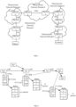
- a DetNet flow sent by an end (Talker) shown in FIG. 1 runs through several interconnected DetNet domains to the other end (Listener).
- different DetNet domains for example, an access network, a converged network and a core network etc. shown in FIG. 1 , may have different planned scheduling cycles, which may lead to inability to perform strict scheduling cycle mapping during transmission of the DetNet flow, thereby affecting transmission of the DetNet flow.
- Embodiments of the present disclosure provide a cross-domain transmission method and apparatus of a DetNet flow and an electronic device, so as to achieve transmission of the DetNet flow across DetNet domains.
- An embodiment of the present disclosure provides the following technical solution.
- the method includes:
- the apparatus includes:
- an electronic device including a processor and a machine readable storage medium;
- An embodiment of the present disclosure further provides a machine readable storage medium storing machine executable instructions executable by a processor; where, the machine executable instructions are executed by a processor to implement the above method.
- the egress node in the last determinist network domain that the DetNet-flow data packet passes through can, based on the actual transmission latency ⁇ t' n of the received DetNet-flow data packet in the present DetNet domain and the actual transmission latencies that the DetNet-flow data packet passes through other DetNet domains, perform time compensation for the DetNet-flow data packet so as to achieve reliable transmission of the DetNet-flow data packet.
- each node may have a same scheduling cycle plan but nodes in different DetNet domains may have different scheduling cycle plans.
- Cg1 and Cg2 belong to a same DetNet domain (denoted as domain 23), and the scheduling cycle plan of the egress interface (denoted as intf1) on the Cg1 and the egress interface (denoted as intf2) on the Cg2 may be same.
- a time length (also called width) of a scheduling cycle is T2 (e.g. 10us), where x2 packets may be buffered in each scheduling cycle.
- Eg2, Cg1 and Eg3 belong to different DetNet domains
- the scheduling cycle plan of the egress interface (denoted as intf0) on the Eg2 the egress interface (denoted as intf1) on the Cg1, and the egress interface (denoted as intf0) on the Eg3 may be different: the time length of the scheduling cycle of the egress interface intf0 on Eg2 is T1 (e.g. 100us) and x1 packets may buffered in each scheduling cycle; the time length of the scheduling cycle of the egress interface intf1 on Cg1 is T2 (e.g.
- x2 packets may be buffered in each scheduling cycle; the time length of the scheduling cycle of the egress interface intf0 on Eg3 is T3 (e.g. 200us) and x3 packets may be buffered in each scheduling cycle.
- an embodiment of the present disclosure provides a cross-domain transmission method of a DetNet flow to achieve cross-domain transmission of the DetNet flow.
- FIG. 3 By abstracting and simplifying multiple DetNet domains, a cross-domain interconnection mathematical model shown in FIG. 3 may be obtained. As shown in FIG. 3 , the DetNet flow is transmitted starting from Talker and reaches the Listener through four interconnected DetNet domains.
- DetNet domains Due to inconsistent clock domains and wide geographically span, different DetNet domains are difficult to achieve time synchronization over the entire network. In this case, it may be first considered to perform domain-specific timing on reference latencies of the each DetNet domain in a deterministic transmission path as shown in FIG. 4 .
- the reference latency of each DetNet domain may be a maximum transmission latency in the DetNet domain.
- ⁇ t 1 be a reference latency of a DetNet domain 1
- ⁇ t 2 be a reference latency of a DetNet domain 2
- ⁇ t 3 be a reference latency of a DetNet domain 3
- ⁇ t 4 be a reference latency of a DetNet domain 4.
- the reference latency of this DetNet domain may be obtained, which will be exemplified below.
- tref represents the above candidate global reference latency
- tfix represents an inter-domain transmission latency between different DetNet domains in the above transmission path, which is generally relatively small and may be approximate to a fixed constant
- k 1 , k 2 and k 3 are the timing ratios of the first three DetNet domains to the DetNet domain 4 where the E-gw4 is located, respectively, which will be exemplified below and not be described herein.
- tref k represents a candidate global reference latency of the k-th path in all equivalent paths.
- the target global reference latency of each path in all equivalent paths may not be the candidate global reference latency actually measured on itself but a candidate global reference latency with a largest value in the candidate global reference latencies of all equivalent paths, so as to ensure the data packets transmitted in each of the equivalent paths have the same target global reference latency, thus reducing jitter.
- the candidate global reference latency of the transmission path may be directly determined as the target global reference latency (S_tref) of the transmission path.
- the actual transmission latency of the DetNet-flow data packet in each DetNet domain is changeable, and the actual transmission latency may be specifically determined based on a difference between an entry time point that the DetNet-flow data packet enters a DetNet domain during actual transmission and a leaving time point that the DetNet-flow data packet leaves the DetNet domain during the actual transmission.
- the actual transmission latency of the DetNet-flow data packet in the DetNet domain may be obtained during transmission of the DetNet flow, which will be exemplified below and will not be described herein.
- ⁇ t' 1 be the actual transmission latency of the DetNet-flow data packet in the DetNet domain 1
- ⁇ t' 2 be the actual transmission latency of the DetNet-flow data packet in the DetNet domain 2
- ⁇ t' 3 be the actual transmission latency of the DetNet-flow data packet in the DetNet domain 3
- ⁇ t' 4 be the actual transmission latency of the DetNet-flow data packet in the DetNet domain 4.
- trel represents the above path transmission latency
- tfix, k 1 , k 2 and k 3 are as mentioned above.
- the egress node (for example, E-gw4) in the last DetNet domain (for example, the DetNet domain 4 as shown in FIG. 3 or 4 ) which the DetNet-flow data packet passes through may determine to-be-actually-compensated time tc of the above DetNet-flow data packet in the entire transmission path.
- k 1i represents a timing ratio of the first DetNet domain that the path i passes through to the last DetNet domain that the path i passes through, and so on.
- ⁇ t' 1i represents the actual transmission latency of the first DetNet domain of the path i that the DetNet-flow data packet passes through, and so on.
- tc S_tref ⁇ tfix i ⁇ k 1 * ⁇ t ′ 1i + k 2 * ⁇ t ′ 2i + ... + k n ⁇ 1 * ⁇ t ′ n ⁇ 1i + ⁇ t ′ ni (latency compensation formula 1).
- the egress node of the last DetNet domain may, based on the tc, determine a corresponding scheduling cycle to schedule transmission of the DetNet flow. Relevant details will be described below and no redundant descriptions are made herein.
- any DetNet domain that the transmission path passes through has one clock source (provided by a clock plane or test instrument online or offline) and each node in a same DetNet domain in the transmission path may perform clock synchronization based on the clock source in the same DetNet domain.
- one clock source may be specified as a reference clock source in this embodiment.
- the reference clock source may be a clock source of any DetNet domain, or a specified clock source independent of any DetNet domain, which is not limited herein in this embodiment.
- a time ratio of the specified reference clock source to the clock source in the DetNet domain 1 is k' 1
- a time ratio of the specified reference clock source to the clock source in the DetNet domain 2 is k' 2
- a time ratio of the specified reference clock source to the clock source in the DetNet domain 3 is k' 3
- a time ratio of the specified reference clock source to the clock source in the DetNet domain 4 is k' 4 , and so on.
- k' 1 , k' 2 , k' 3 , k' 4 can be obtained offline before path planning.
- k' n refers to a time ratio of the specified reference clock source to the clock source in the last DetNet domain.
- each DetNet domain usually, the latency change of each DetNet domain is relatively small.
- a timing offset between each of the DetNet domains may be negligible, that is, the above k' 1 , k' 2 , k' 3 , k' 4 ... k' n may be considered as 1.
- a to-be-compensated latency of a certain DetNet domain is 2ms, but the offset caused by timing is 0.2us, which is one ten-thousandth of the above latency 2ms.
- the above timing offset may be completely negligible, that is, the above k' 1 , k' 2 , k' 3 , k' 4 ... k' n may be considered as 1.
- an ingress node of the DetNet-flow data packet in each DetNet domain is as shown in FIG. 6 .
- the ingress node in each DetNet domain shown in FIG. 6 is marked as GwIdO, GwId1, ..., GwIdn-1 sequentially.
- DCTIList deterministic latency compensation information
- the DCTIList information may include the followings.
- the Cmd field is set to an instruction value a1, for example, 1, it indicates to record the time point (denoted as packet reception time point) of receiving the packet, for example, the DetNet-flow data packet or the reference latency measurement packet, into the temp time info field. If the Cmd is set to an instruction value a1 for example, 1, the operation is usually performed by the ingress node in the first DetNet domain (such as GwIdO shown in FIG. 6 ).
- the Cmd field is set to an instruction value a2, for example, 2, it indicates to determine a latency of the packet, for example, the DetNet-flow data packet or the reference latency measurement packet, in the current DetNet domain.
- the latency is specifically a residence time, and in an application to a scenario of transmitting the DetNet-flow data packet, the latency is an actual transmission latency.
- the operation may include: obtaining, from the temp time info field, the packet reception time point (denoted as Time1) that the ingress node in the present DetNet domain receives the packet, for example, the DetNet-flow data packet or the reference latency measurement packet, and determining the packet reception time point (denoted as Time2) that the present node receives the packet, for example, the DetNet-flow data packet or the reference latency measurement packet, and then determining a latency of the packet in the current DetNet domain as Time2-Time1.
- the Cmd field is set to an instruction value a2, for example, 2, the operation is usually performed by an egress node (such as GwIdn shown in FIG. 6 ) in the last DetNet domain.
- the Cmd field When the Cmd field is set to an instruction value a3, for example, 3, it may indicate the following two operations.
- One of the operations is to store the latency of the packet, for example, the DetNet-flow data packet or the reference latency measurement packet in the previous DetNet domain into the residence time list in the information item corresponding to the ingress node in the previous DetNet domain; where, in an application to a scenario of collecting the reference latency, the latency is specifically a residence time; in an application to a scenario of transmitting the DetNet-flow data packet, the latency is an actual transmission latency.
- the specific operation may include: obtaining, from the temp time info field, the packet reception time point (denoted as Time1) that the ingress node (e.g.
- I-Gw) in the previous DetNet domain receives the packet, for example, the DetNet-flow data packet or the reference latency measurement packet; obtaining, from a specified position, a packet sending time point (denoted as Time2) that an egress node in the previous DetNet domain sends the packet, for example, the DetNet-flow data packet or the reference latency measurement packet; calculating a latency of the packet, for example, the DetNet-flow data packet or the reference latency measurement packet in the previous DetNet domain as Time2-Time1; recording the calculated latency of the previous DetNet domain into the residence time list in the information item corresponding to the previous DetNet domain.
- a packet sending time point denoted as Time2
- the other operation is to record the packet reception time point that the present node receives the packet, for example, the DetNet-flow data packet or the reference latency measurement packet into the temp time info field. If the Cmd field is set to an instruction value a3, for example, 3, the operations are usually performed by an ingress node in other DetNet domains other than the first DetNet domain.
- Rate field which may occupy 11 bits.
- the packet for example, the DetNet-flow data packet or the reference latency measurement packet, may carry a respective Rate field corresponding to each DetNet domain that the packet passes through, where the respective rate field corresponding to each DetNet domain is used to carry the Rate of the corresponding DetNet domain.
- the rate of each DetNet domain may be obtained by converting the measured timing ratio of the DetNet domain to the last DetNet domain that the packet passes through (e.g. k 1 and k 2 mentioned above), which will be detailed below. No redundant descriptions are made herein.
- the highest bit of the Rate represents positive or negative offset: when the highest bit is a first value, for example, 0, it indicates a positive offset; when the highest bit is a second value, for example, 1, it indicates a negative offset.
- the offset per millisecond is 1023ns (about 1us) at most. It should be noted that if the value of the Rate itself is 0, it indicates no frequency offset compensation is required.
- Latency field (residence time list), as an embodiment, the residence time list may occupy 32 bits.
- the residence time list can carry a residence time of the reference latency measurement packet in the DetNet domain, with the details referred to the following embodiments of collecting the reference latency.
- the residence time list can carry an actual transmission latency of the DetNet-flow data packet in the DetNet domain, with the details referred to the following embodiments of transmitting the DetNet-flow data packet.
- a reference latency measurement packet is firstly constructed at the ingress node in the first DetNet domain, i.e. at I-Gw1 in the DetNet domain 1.
- the reference latency measurement packet may carry the DCTIList information.
- the DCTIList information has a structure shown in FIG. 7 .
- the DCTIList information field at least includes a Flag field, a Pointer, a Compensation cap field, a temp time info field, a respective information item corresponding to the ingress node in each DetNet domain that the reference latency measurement packet passes through, and an information item corresponding to the egress node in the last DetNet domain.
- the Flag field is set to a value4, for example, 3, to indicate collecting the reference latency.
- the Compensation cap field may be null or a pre-measured Compensation cap value.
- each of the information items at least includes: a node identifier field, a Cmd field, a Rate field and a residence time list.
- the Cmd field in the information item corresponding to the ingress node in the first DetNet domain is set to an instruction value a1, for example, 1.
- the Cmd field is set to an instruction value a3, for example, 3.
- the Cmd field is set to an instruction value a2, for example, 2.
- the Rate field and the residence time list in each information item may be null or a preset value.
- FIG. 8 illustrates the DCTIList information field carried by the reference latency measurement packet at the ingress node I-Gw1 in the first DetNet domain.
- I-Gw1 as the ingress node in the first DetNet domain, i.e. the DetNet domain 1, based on the Cmd field being set to the instruction value a1, for example, 1, records the time point at which the reference latency measurement packet is successfully constructed into the temp time info field, and points the Pointer to a next information item (i.e. the information item corresponding to the ingress node in the next DetNet domain).
- I-Gw1 sends the reference latency measurement packet in the DetNet domain 1.
- E-Gw1 in the DetNet domain 1 receives the reference latency measurement packet.
- the E-Gw1 in the DetNet domain 1 When the E-Gw1 in the DetNet domain 1 sends the reference latency measurement packet, it may mark a packet sending time point of sending the reference latency measurement packet at a specified position of the reference latency measurement packet and then send the reference latency measurement packet.
- I-Gw2 in the DetNet domain 2 receives the reference latency measurement packet and identifies the information item corresponding to the I-Gw2 from the reference latency measurement packet. If the Cmd field in the information item is set to the instruction value a3, for example, 3, the following two operations are performed.
- One of the operations is to determine a residence time of the reference latency measurement packet in a previous DetNet domain, i.e. the DetNet domain 1, and store the residence time into the residence time list in the information item corresponding to the previous DetNet domain (i.e. the information item indicated by GwIdO).
- the operation may include: obtaining the packet reception time point (referring to the time point of constructing the reference latency measurement packet) of the ingress node, i.e. I-Gw1, of the previous DetNet domain, i.e. the DetNet domain 1, from the temp time info field of the reference latency measurement packet, the packet reception time point being Time1; picking out the packet sending time point Time_2 of the egress node, i.e.
- E-Gw1 in the previous DetNet domain, i.e. the DetNet domain 1, from the specified position of the reference latency measurement packet; calculating a residence time of the reference latency measurement packet in the previous DetNet domain, i.e. the DetNet domain 1 as Time2-Time1; recording the residence time Time2-Time1 into the Residence time list in the information item corresponding to the previous DetNet domain, i.e. the DetNet domain 1 (i.e. information item indicated by GwIdO); afterwards, pointing the Pointer to the next information item (i.e. the information item corresponding to the ingress node in the next DetNet domain).
- the other operation is that the present I-GW2 records the packet reception time point of receiving the reference latency measurement packet into the temp time info field.
- I-Gw2 in the DetNet domain 2 sends the reference latency measurement packet in the DetNet domain 2.
- E-Gw2 in the DetNet domain 2 receives the reference latency measurement packet.
- the E-Gw2 may mark the packet sending time point of sending the reference latency measurement packet on a specified position of the reference latency measurement packet and then continue to send the reference latency measurement packet.
- I-Gw3 in the DetNet domain 3 receives the reference latency measurement packet, which performs operations similar to those performed by I-Gw2 and thus no redundant descriptions are made herein.
- E-Gw3 in the DetNet domain 3 receives the reference latency measurement packet, which performs operations similar to those performed by E-Gw2.
- the E-Gwn After receiving the reference latency measurement packet, the E-Gwn identifies the information item corresponding to the present E-Gwn from the reference latency measurement packet. If it is found that the Cmd field in the information item is set to the instruction value a2, for example, 2, the following operation is performed: obtaining the packet reception time point (denoted as t'Ingress) that the ingress node i.e. I-Gwn, in the present DetNet domain receives the reference latency measurement packet from the temp time info field of the reference latency measurement packet, and calculating a residence time tres of the reference latency measurement packet in the present DetNet domain, i.e. the last DetNet domain.
- the ⁇ t' includes a time required for completing the processing on the reference latency measurement packet based on the set measurement packet processing manner, such as calculation and various processing operations.
- the ⁇ t' is a time difference between the packet reception time point t'Received of receiving the reference latency measurement packet and the time point t'Ready of completing processing and preparing to send the reference latency measurement packet.
- the ⁇ t' may be set based on actual requirements.
- the E-Gwn records the tres into the residence time list in the information item corresponding to the I-Gwn (i.e. information item indicated by GwIdn-1) as shown in FIG. 9 .
- the residence time list in the information item corresponding to the E-Gwn (i.e. information item indicated by GwIdn) shown in FIG. 9 may be null or a specified value, which is not used for subsequently determining the reference latency.
- the E-Gwn reports the residence time in each residence time list in the reference latency measurement packet to a control plane such that the control plane, based on the transmission path of the reference latency measurement packet, evaluates and adjusts the residence time in each residence time list to determine the reference latency of each DetNet domain, i.e. the above ⁇ t 1 , ⁇ t 2 , ... ⁇ t n .
- the control plane calculates a target global reference latency S_tref of the transmission path of the reference latency measurement packet. For example, as mentioned above, if the transmission path of the reference latency measurement packet and other k-1 paths are mutually equivalent paths, the target global reference latency S_tref of the transmission path of the reference latency measurement packet may be determined based on the above global reference latency formula 1 in this embodiment; if the transmission path of the reference latency measurement packet has no equivalent path, the target global reference latency S_tref of the transmission path of the reference latency measurement packet may be determined based on the above global reference latency formula 2 in this embodiment.
- control plane may further calculate the compensation cap value, i.e., (S_tref -tfix i ) in the above latency compensation formula 1 or (S_tref -tfix) in the above latency compensation formula 2.
- the compensation cap value i.e., (S_tref -tfix i ) in the above latency compensation formula 1 or (S_tref -tfix) in the above latency compensation formula 2.
- the control plane constructs a DetNet-flow information table as shown in FIG. 10 .
- a DetNet-flow information entry corresponding to each DetNet flow includes corresponding DCTIList information.
- the control plane may distribute the DetNet-flow information table to the ingress node in the first DetNet domain that the DetNet flow passes through, for example, the above I-GW1.
- FIG. 11 is a schematic diagram illustrating cross-domain transmission according to an embodiment of the present disclosure.
- the DetNet-flow data packet originated by the Talker may pass through the following three DetNet domains: a DetNet domain 1, a DetNet domain 2 and a DetNet domain 3.
- Eg1 is an ingress node by which the DetNet-flow data packet enters the DetNet domain 1
- Eg2 is an egress node by which the DetNet-flow data packet leaves the DetNet domain 1
- Cg1 is an ingress node by which the DetNet-flow data packet enters the DetNet domain 2
- Cg2 is an egress node by which the DetNet-flow data packet leaves the DetNet domain 2
- Eg3 is an ingress node by which the DetNet-flow data packet enters the DetNet domain 3
- Eg4 is an egress node by which the DetNet-flow data packet leaves the DetNet domain 3.
- the Eg1 when the Eg1 receives a DetNet-flow data packet (denoted as packet 110) sent by the Talker, it records a time point (i.e. packet reception time point, illustrated by Ingress timestamp of GwIdO in FIG. 12 ) that the present Eg1 receives the packet 110, and based on the DetNet-flow information carried in the packet 110 (e.g. IP 5-tuple+equivalent path number, where the equivalent paths are used to achieve multi-path reliability of PREOF), determines an identifier (FlowID) of the DetNet flow to which the packet 110 belongs, and based on the FlowID, queries the local DetNet-flow information table shown in FIG.
- FlowID identifier
- the DCTIList information encapsulated in the packet 110 may correspond to the DCTIList information in the queried DetNet-flow information entry.
- the DCTIList information encapsulated in the packet 110 at least includes a Flag field, a Pointer, a Compensation cap field, a temp time info field, a respective information item corresponding to the ingress node in each DetNet domain that the packet 110 passes through and an information item corresponding to the egress node in the last DetNet domain.
- the Flag field is set to a value3, for example, 2, to indicate the frequency offset cannot be neglected.
- the Compensation cap field may be a pre-obtained Compensation cap value.
- each information item at least includes: a node identifier field, a Cmd field, a Rate field, a residence time list.
- the Cmd field is set to an instruction value a1, for example, 1, and the Rate field carries the Rate of the present DetNet domain.
- the Cmd field is set to an instruction value a3, for example, 3, and the Rate field carries the Rate of the present DetNet domain, for example, 1.
- the Cmd field is set to an instruction value a2, for example, 2, and the Rate field carries the Rate of the present DetNet domain, for example, 1.
- the residence time list in the information item corresponding to the ingress node or egress node in each DetNet domain may be null or the reference latency of the DetNet domain.
- the above DCTIList information may also be carried in the packet 110 before reaching Eg1.
- the Talker carries the above DCTIList information in the packet 110 to be sent, or a device between the Talker and Eg1 carries the above DCTIList information upon receiving the packet 110, and so on, which is not limited herein.
- the Eg1 based on the Cmd field in the information item corresponding to the Eg1 being set to the instruction value a1, for example, 1, the Eg1 records the packet reception time point Ingress timestamp of GwIdO of receiving the packet 110 into the above temp time info field, and point the above Pointer to the information item (information item where GwId1 is located) corresponding to the ingress node in the next DetNet domain, i.e. the DetNet domain 2, as shown in FIG. 12 .
- the packet 110 encapsulated with the DCTIList information may be denoted as packet 111.
- Eg1 firstly stores the packet 111 into an elastic buffer as shown in FIG. 13 .
- the purpose of introducing the elastic buffer is to eliminate excess demand of burst DetNet-flow data packets for resources.
- Eg1 distributes the packets in the Elastic Buffer to a corresponding scheduling queue of each scheduling cycle.
- the Eg1 schedules the packets in the scheduling queue corresponding to the scheduling cycle for transmission in the DetNet domain 1.
- the Eg2 After receiving the packet 111, the Eg2 stores the packet into a scheduling queue of the corresponding scheduling cycle, and when the corresponding scheduling cycle arrives, schedules the packet 111 in the scheduling queue corresponding to the scheduling cycle to continue transmission.
- the Eg2 may mark a time point of sending the packet (i.e. packet sending time point) at a specified position of the packet 111.
- the Cg1 receives the packet 111 and identifies the information item corresponding to the present Cg1 from the packet 111; when it is found that the Cmd field in the information item is set to an instruction value a3, for example, 3, the following two operations are performed.
- One of the operations is to determine the actual transmission latency of the previous DetNet domain, i.e. the DetNet domain 1, which the packet 111 passes through, for example, the above ⁇ t' 1 , and store it into the residence time list in the information item corresponding to the previous domain (i.e. information item indicated by GwIdO).
- the operation may include: obtaining the packet reception time point (set as Time1) of the ingress node, i.e. the Eg1, in the previous DetNet domain, i.e. the DetNet domain 1, from the temp time info field of the packet 111; picking out a packet sending time point (set as Time2) of the egress node, i.e. the Eg2, in the previous DetNet domain, i.e.
- the DetNet domain 1 from a packet specified position of the packet 111; determining the actual transmission latency of the packet 111 passing through the previous DetNet domain, i.e. the DetNet domain 1 as Time2-Time1; recording the actual transmission latency Time2-Time1 into the residence time list in the corresponding information item (i.e. the information item indicated by GwIdO) in the previous DetNet domain, i.e. the DetNet domain 1, and at the same time, pointing the Pointer in the DCTIList information field to the information item (the information item indicated by GwId2) corresponding to a next DetNet domain, i.e. the DetNet domain 3.
- the other operation is that the present Cg1 records the time point of receiving the packet 111 (denoted as packet reception time point) into the temp time info field.
- the Cg1 firstly stores the packet 111 into the Elastic Buffer shown in FIG. 13 and then schedules the packets in the Elastic Buffer based on the First In, First Out method, so as to store them into a scheduling queue corresponding to each scheduling cycle.
- the Cg1 schedules the packets in the scheduling queue corresponding to the scheduling cycle to be transmitted in the DetNet domain 2.
- the Cg2 With scheduling the packet 111 to be transmitted in the DetNet domain 2 as an example, after receiving the packet 111, the Cg2 stores the packet into the scheduling queue of the corresponding scheduling cycle. And when the corresponding scheduling cycle arrives, the Cg2 schedules the packet 111 in the scheduling queue corresponding to the scheduling cycle. When sending the packet 111, the Cg2 may mark a time point of sending the packet 111 (i.e. packet sending time point) at a specified position of the packet 111.
- the Eg3 receives the packet 111 and identifies the information item corresponding to the present Eg3 from the packet 111; when it is found that the Cmd field in the information item is set to an instruction value a3, for example, 3, the following two operations are performed.
- One of the operations is to determine the actual transmission latency of the packet 111 passing through the previous DetNet domain, i.e. the DetNet domain 2, for example, the above ⁇ t' 2 , and store it into the residence time list in the information item corresponding to the previous DetNet domain (i.e. the information item indicated by GwId1).
- the operation may include: obtaining the packet reception time point (set as Time1) of the ingress node in the previous DetNet domain, i.e. Cg1 in the DetNet domain 2 from the temp time info field of the packet 111; picking out a packet sending time point (denoted as Time2) of the egress node, i.e. the Cg2, in the previous DetNet domain, i.e.
- the DetNet domain 2 from a specified position of the packet 111; determining the actual transmission latency of the packet 111 passing through the previous DetNet domain, i.e. the DetNet domain 2, as Time2-Time1; recording the actual transmission latency Time2-Time1 into the information item (the information item indicated by GwId1) corresponding to the ingress node in the previous DetNet domain, i.e. Cg1 in the DetNet domain 2.
- the other operation is that the present Eg3 records the time point of receiving the packet 111 (i.e. packet reception time point) into the temp time info field.
- the Eg3 firstly stores the packet 111 into the Elastic Buffer shown in FIG. 13 and then schedules the packets in the Elastic Buffer based on the First In, First Out method, so as to store them into a scheduling queue corresponding to each scheduling cycle.
- the Eg3 schedules the packets in the scheduling queue corresponding to the scheduling cycle to be transmitted in the DetNet domain 3.
- the Eg4 After receiving the packet 111, the Eg4 records the time point of receiving the packet 111 (i.e. packet reception time point, denoted as tReceived).
- a hardware controller in the Eg4 after receiving the packet 111, marks the time point of receiving the packet 111 (i.e. packet reception time point, denoted as tReceived) onto a specified position in the header of the packet 111.
- Eg4 identifies the information item corresponding to the present node from the packet 111.
- the Cmd field in the information item is set to an instruction value a2, for example, 2
- the actual transmission latency of the current DetNet domain is determined, which specifically includes: picking out the packet reception time point (set as tIngress) that the ingress node, i.e. the Eg3, in the present DetNet domain 3 receives the packet 111 from the temp time info field in the packet 111.
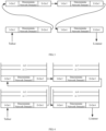
- FIG. 14 illustrates tReady and ⁇ t.
- FIG. 15 illustrates the packet 111.
- Eg4 picks out the actual transmission latency carried in each residence time list in the information items corresponding to other DetNet domains carried in the packet 111, i.e. ⁇ t' 1 and ⁇ t' 2 in the above latency compensation formulas, and at the same time, picks out Rates, i.e. Rate1 and Rate 2 in each information item.
- Rate1 represents the number of nanoseconds to-be-compensated per millisecond for the first DetNet domain, i.e. the DetNet domain 1 relative to the last DetNet domain, i.e. the DetNet domain 3, which is obtained by converting the above k 1 , and so on.
- the Eg4 determines a corresponding target scheduling cycle, and places the above packet 111 into a periodic scheduling queue corresponding to the target scheduling cycle.
- the packet 111 enters the periodic scheduling queue corresponding to the scheduling cycle 6.
- the packet 111 may be scheduled.
- time compensation is performed for the packet 111 at the egress node in the last DetNet domain. Such time compensation at the egress node in the last DetNet domain can ensure the final compensation latency is bounded, thereby reducing a jitter range.
- FIG. 17 is a structural diagram illustrating an apparatus according to an embodiment of the present disclosure.
- the apparatus is applied to a network node in a DetNet domain.
- the apparatus includes:
- the first processing unit is configured to, if the network node is an ingress node in a first DetNet domain that the DetNet-flow data packet passes through, further obtain a packet reception time point that the present node receives the DetNet-flow data packet; the second processing unit is further configured to schedule and transmit the DetNet-flow data packet in the first DetNet domain, where the DetNet-flow data packet carries a time information Temp time info field. The packet reception time point that the present node receives the DetNet-flow data packet is carried in the Temp time info field.
- the first processing unit is configured to, if the network node is an ingress node in any DetNet domain other than a first DetNet domain that the DetNet-flow data packet passes through, further determine an actual transmission latency of the DetNet-flow data packet when passing through a previous DetNet domain, and record the determined actual transmission latency into an information item which is carried in the DetNet-flow data packet and corresponds to the previous DetNet domain; the second processing unit is configured to further record a reception time point that the network node receives the DetNet-flow data packet into the Temp time info field carried in the DetNet-flow data packet and send the DetNet-flow data packet.
- determining the actual transmission latency of the DetNet-flow data packet when passing through the previous DetNet domain includes: obtaining Time1 from the Temp time info field, where the Time1 represents the packet reception time point that the ingress node in the previous DetNet domain receives the DetNet-flow data packet; obtaining Time2 from a specified position of the DetNet-flow data packet, where the Time2 represents a packet sending time point that an egress node in the previous DetNet domain sends the DetNet-flow data packet; calculating a difference between the Time2 and the Time1, and based on the difference between the Time2 and the Time1, determining an actual transmission latency of the DetNet-flow data packet when passing through the previous DetNet domain.
- determining the to-be-compensated time tc includes: based on the ⁇ t' n , the actual transmission latencies of the DetNet-flow data packet when passing through other DetNet domains, Rate; and a compensation cap value, calculating the to-be-compensated time tc.
- the DetNet-flow data packet carries the actual transmission latencies of the DetNet-flow data packet when passing through other DetNet domains;
- the Rate represents the number of nanoseconds to be compensated per millisecond for an i-th DetNet domain relative to a target network domain, and the target network domain is the last DetNet domain;
- the DetNet-flow data packet carries the Rates of other DetNet domains relative to the target network domain and the DetNet-flow data packet carries the compensation cap value.
- the S_tref represents a target global reference latency of the transmission path of the DetNet-flow data packet
- the first processing unit is configured to, in the process of collecting candidate global reference latency of the transmission path, if the network node is an ingress node of the first DetNet domain in the transmission path, construct a reference latency measurement packet; the second processing unit is configured to further send the reference latency measurement packet in the first DetNet domain; where the reference latency measurement packet at least carries the Temp time info field carrying a time point that the present node receives the reference latency measurement packet, and the time point is a time point that the reference latency measurement packet is successfully constructed;
- FIG. 18 is a structural diagram illustrating an electronic device provided by an embodiment of the present disclosure.
- the hardware structure may include a processor and a machine readable storage medium, where the machine readable storage medium stores machine executable instructions executable by the processor; and the processor is configured to execute the machine executable instructions to perform the method provided by the above embodiments of the present disclosure.
- an embodiment of the present disclosure further provides a machine readable storage medium, storing several computer instructions, where the computer instructions are executed by a processor to implement the method in the above embodiments of the present disclosure.
- the machine readable storage medium mentioned herein may be any of electronic storage devices, magnetic storage devices, optical storage devices or other physical storage devices and may contain or store information such as executable instructions, data and so on.
- the machine readable storage medium may be a Radom Access Memory (RAM), a volatile memory, a non-volatile memory, a flash memory, a storage drive (e.g. hard disk drive), a solid state disk, any type of storage disk (e.g., compact disk, Digital Video Disk (DVD)), or a similar storage medium, or a combination thereof.
- the systems, apparatuses, modules or units described in the above embodiments may be specifically implemented by a computer chip or an entity or may be implemented by a product with a certain function.
- a typical implementing device may be a computer and the computer may be specifically a personal computer, a laptop computer, a cellular phone, a camera phone, a smart phone, a personal digital assistant, a media player, a navigation device, an email transceiver, a game console, a tablet computer, a wearable device, or a combination of any several devices of the above devices.
- the above apparatus is divided into different units based on functionality for descriptions.
- the functions of different units may be implemented in a same or a plurality of software and/or hardware when practicing the present disclosure.
- the examples of the present disclosure may be provided as a method, a system, or a computer program product.
- entire hardware examples, entire software examples or examples combining software and hardware may be adopted in the present disclosure.
- the present disclosure may take the form of a computer program product that is implemented on one or more computer available storage media (including but not limited to magnetic disk memory, CD-ROM, and optical memory and so on) including computer available program codes.
- These computer program instructions may be provided to a general-purpose computer, a dedicated computer, an embedded processor, or a processor of another programmable data processing device to generate a machine so that the instructions executed by a computer or a processor of another programmable data processing device generate an apparatus for implementing functions designated in one or more flows of the flowcharts and/or one or more blocks of the block diagrams.
- these computer program instructions may also be stored in a computer readable memory that can direct a computer or another programmable data processing device to work in a particular manner so that the instructions stored in the computer readable memory generate a product including an instruction apparatus and the instruction apparatus can implement functions designated in one or more flows of the flowcharts and/or one or more blocks of the block diagrams.
- the computer program instructions may also be loaded on a computer or another programmable data processing device, so that a series of operation blocks can be executed on the computer or another programmable device to generate processing achieved by the computer, and thus instructions executable on the computer or another programmable device are provided for blocks for realizing functions designated in one or more flows of the flowcharts and/or one or more blocks of the block diagrams.
Landscapes
- Engineering & Computer Science (AREA)
- Computer Networks & Wireless Communication (AREA)
- Signal Processing (AREA)
- Environmental & Geological Engineering (AREA)
- Data Exchanges In Wide-Area Networks (AREA)
- Synchronisation In Digital Transmission Systems (AREA)
Applications Claiming Priority (1)
| Application Number | Priority Date | Filing Date | Title |
|---|---|---|---|
| PCT/CN2022/143921 WO2024138634A1 (zh) | 2022-12-30 | 2022-12-30 | 确定性流跨域传输方法、装置及电子设备 |
Publications (3)
| Publication Number | Publication Date |
|---|---|
| EP4425871A1 true EP4425871A1 (de) | 2024-09-04 |
| EP4425871A4 EP4425871A4 (de) | 2025-02-12 |
| EP4425871B1 EP4425871B1 (de) | 2026-03-11 |
Family
ID=91716040
Family Applications (1)
| Application Number | Title | Priority Date | Filing Date |
|---|---|---|---|
| EP22966010.5A Active EP4425871B1 (de) | 2022-12-30 | 2022-12-30 | Verfahren und vorrichtung zur deterministischen fluss-übergreifenden übertragung sowie elektronische vorrichtung |
Country Status (3)
| Country | Link |
|---|---|
| EP (1) | EP4425871B1 (de) |
| CN (1) | CN118414817A (de) |
| WO (1) | WO2024138634A1 (de) |
Family Cites Families (4)
| Publication number | Priority date | Publication date | Assignee | Title |
|---|---|---|---|---|
| US10798012B2 (en) * | 2017-10-30 | 2020-10-06 | Cisco Technology, Inc. | Jitter elimination and latency compensation at DetNet transport egress |
| CN113382442B (zh) * | 2020-03-09 | 2023-01-13 | 中国移动通信有限公司研究院 | 报文传输方法、装置、网络节点及存储介质 |
| CN115348216A (zh) * | 2021-05-14 | 2022-11-15 | 华为技术有限公司 | 报文转发的方法和相关装置 |
| WO2023283902A1 (zh) * | 2021-07-15 | 2023-01-19 | 新华三技术有限公司 | 一种报文传输方法及装置 |
-
2022
- 2022-12-30 CN CN202280005437.7A patent/CN118414817A/zh active Pending
- 2022-12-30 EP EP22966010.5A patent/EP4425871B1/de active Active
- 2022-12-30 WO PCT/CN2022/143921 patent/WO2024138634A1/zh not_active Ceased
Also Published As
| Publication number | Publication date |
|---|---|
| CN118414817A (zh) | 2024-07-30 |
| EP4425871B1 (de) | 2026-03-11 |
| WO2024138634A1 (zh) | 2024-07-04 |
| EP4425871A4 (de) | 2025-02-12 |
Similar Documents
| Publication | Publication Date | Title |
|---|---|---|
| JP6502492B2 (ja) | パケット交換ネットワークを介した低ジッタ通信のためのシステム、装置及び方法 | |
| US8068429B2 (en) | Transmit scheduling | |
| JP6192995B2 (ja) | 通信装置、通信システム、通信方法およびコンピュータプログラム | |
| Kwak et al. | A new double two-way ranging algorithm for ranging system | |
| KR20150143801A (ko) | 타임스탬프를 생성하는 방법, 장치, 그리고 시스템 | |
| JP7683047B2 (ja) | 決定論的ネットワークに適用されるcsqfスケジューリングサイクルを収集するための方法及び装置 | |
| US12057930B2 (en) | Synchronizing a distributed application via a communication network | |
| Pocovi et al. | Measurement framework for assessing reliable real-time capabilities of wireless networks | |
| CN108737007A (zh) | 一种时间同步方法、装置及设备 | |
| CN106850397A (zh) | 物联网中消息传递方法和装置 | |
| JP2024520161A (ja) | 決定論的フロー伝送方法およびデバイス | |
| JPWO2016084334A1 (ja) | 可用帯域推定システム、可用帯域推定方法、受信装置及び受信装置の制御プログラム | |
| US20180176872A1 (en) | Metered interface | |
| US20240250913A1 (en) | Method of adjusting scheduling cycle and network device | |
| EP4425871A1 (de) | Verfahren und vorrichtung zur deterministischen fluss-übergreifenden übertragung sowie elektronische vorrichtung | |
| EP4425896B1 (de) | Deterministisches stream-übertragungsverfahren und system sowie elektronische vorrichtung | |
| WO2021208868A1 (zh) | 确定时钟的方法和相关装置 | |
| CN101420281B (zh) | 用于在网络要素之间传送日内时间值的方法和装置 | |
| WO2020132834A1 (zh) | 一种打戳处理方法及装置 | |
| Mills et al. | Highball: a high speed, reserved-access, wide area network | |
| CN117835310A (zh) | 一种时延测量方法及装置 | |
| WO2025000383A1 (zh) | 确定性流传输方法、装置、电子设备及机器可读存储介质 | |
| JP2020202498A (ja) | 時刻同期装置、時刻同期システム、時刻同期方法及びプログラム | |
| Liu et al. | Information feedback for estimation and fusion in long-haul sensor networks | |
| JP3278794B2 (ja) | 分散型実時間連続メディア処理装置 |
Legal Events
| Date | Code | Title | Description |
|---|---|---|---|
| STAA | Information on the status of an ep patent application or granted ep patent |
Free format text: STATUS: UNKNOWN |
|
| STAA | Information on the status of an ep patent application or granted ep patent |
Free format text: STATUS: THE INTERNATIONAL PUBLICATION HAS BEEN MADE |
|
| PUAI | Public reference made under article 153(3) epc to a published international application that has entered the european phase |
Free format text: ORIGINAL CODE: 0009012 |
|
| STAA | Information on the status of an ep patent application or granted ep patent |
Free format text: STATUS: REQUEST FOR EXAMINATION WAS MADE |
|
| 17P | Request for examination filed |
Effective date: 20240529 |
|
| AK | Designated contracting states |
Kind code of ref document: A1 Designated state(s): AL AT BE BG CH CY CZ DE DK EE ES FI FR GB GR HR HU IE IS IT LI LT LU LV MC ME MK MT NL NO PL PT RO RS SE SI SK SM TR |
|
| A4 | Supplementary search report drawn up and despatched |
Effective date: 20250113 |
|
| RIC1 | Information provided on ipc code assigned before grant |
Ipc: H04L 47/28 20220101ALI20250107BHEP Ipc: H04L 45/00 20220101ALI20250107BHEP Ipc: H04L 43/08 20220101AFI20250107BHEP |
|
| GRAP | Despatch of communication of intention to grant a patent |
Free format text: ORIGINAL CODE: EPIDOSNIGR1 |
|
| STAA | Information on the status of an ep patent application or granted ep patent |
Free format text: STATUS: GRANT OF PATENT IS INTENDED |
|
| DAV | Request for validation of the european patent (deleted) | ||
| DAX | Request for extension of the european patent (deleted) | ||
| INTG | Intention to grant announced |
Effective date: 20251128 |
|
| P01 | Opt-out of the competence of the unified patent court (upc) registered |
Free format text: CASE NUMBER: UPC_APP_0015800_4425871/2025 Effective date: 20251204 |
|
| GRAS | Grant fee paid |
Free format text: ORIGINAL CODE: EPIDOSNIGR3 |
|
| GRAA | (expected) grant |
Free format text: ORIGINAL CODE: 0009210 |
|
| STAA | Information on the status of an ep patent application or granted ep patent |
Free format text: STATUS: THE PATENT HAS BEEN GRANTED |
|
| AK | Designated contracting states |
Kind code of ref document: B1 Designated state(s): AL AT BE BG CH CY CZ DE DK EE ES FI FR GB GR HR HU IE IS IT LI LT LU LV MC ME MK MT NL NO PL PT RO RS SE SI SK SM TR |
|
| REG | Reference to a national code |
Ref country code: CH Ref legal event code: F10 Free format text: ST27 STATUS EVENT CODE: U-0-0-F10-F00 (AS PROVIDED BY THE NATIONAL OFFICE) Effective date: 20260311 Ref country code: GB Ref legal event code: FG4D |
|
| REG | Reference to a national code |
Ref country code: DE Ref legal event code: R096 Ref document number: 602022032378 Country of ref document: DE |
|
| REG | Reference to a national code |
Ref country code: IE Ref legal event code: FG4D |