EP4425812A1 - Communication method, apparatus and system - Google Patents
Communication method, apparatus and system Download PDFInfo
- Publication number
- EP4425812A1 EP4425812A1 EP21965143.7A EP21965143A EP4425812A1 EP 4425812 A1 EP4425812 A1 EP 4425812A1 EP 21965143 A EP21965143 A EP 21965143A EP 4425812 A1 EP4425812 A1 EP 4425812A1
- Authority
- EP
- European Patent Office
- Prior art keywords
- sequence
- bits
- ber
- subsequence
- fec code
- Prior art date
- Legal status (The legal status is an assumption and is not a legal conclusion. Google has not performed a legal analysis and makes no representation as to the accuracy of the status listed.)
- Pending
Links
- 238000000034 method Methods 0.000 title claims abstract description 146
- 230000006854 communication Effects 0.000 title claims abstract description 66
- 238000004891 communication Methods 0.000 title claims abstract description 66
- 238000012360 testing method Methods 0.000 claims abstract description 211
- 238000012937 correction Methods 0.000 claims abstract description 26
- 230000002159 abnormal effect Effects 0.000 claims description 146
- 230000015654 memory Effects 0.000 claims description 42
- 238000004590 computer program Methods 0.000 claims description 18
- 238000012549 training Methods 0.000 claims description 11
- 238000011056 performance test Methods 0.000 abstract description 37
- 230000007774 longterm Effects 0.000 abstract 1
- 230000033590 base-excision repair Effects 0.000 description 502
- 230000005540 biological transmission Effects 0.000 description 65
- 230000006870 function Effects 0.000 description 58
- 238000013461 design Methods 0.000 description 26
- 238000012545 processing Methods 0.000 description 24
- 238000007667 floating Methods 0.000 description 15
- 101100124609 Caenorhabditis elegans zyg-12 gene Proteins 0.000 description 14
- 230000008569 process Effects 0.000 description 14
- 238000010276 construction Methods 0.000 description 12
- 238000010586 diagram Methods 0.000 description 11
- 230000001960 triggered effect Effects 0.000 description 7
- 230000001360 synchronised effect Effects 0.000 description 5
- 238000004364 calculation method Methods 0.000 description 3
- 238000001514 detection method Methods 0.000 description 3
- 238000005516 engineering process Methods 0.000 description 3
- 238000010998 test method Methods 0.000 description 3
- 238000004519 manufacturing process Methods 0.000 description 2
- 238000012986 modification Methods 0.000 description 2
- 230000004048 modification Effects 0.000 description 2
- 239000004984 smart glass Substances 0.000 description 2
- 230000003068 static effect Effects 0.000 description 2
- 238000012795 verification Methods 0.000 description 2
- 238000005406 washing Methods 0.000 description 2
- 230000007175 bidirectional communication Effects 0.000 description 1
- 230000008878 coupling Effects 0.000 description 1
- 238000010168 coupling process Methods 0.000 description 1
- 238000005859 coupling reaction Methods 0.000 description 1
- 230000003993 interaction Effects 0.000 description 1
- 230000003287 optical effect Effects 0.000 description 1
- 230000002195 synergetic effect Effects 0.000 description 1
Images




Classifications
-
- H—ELECTRICITY
- H04—ELECTRIC COMMUNICATION TECHNIQUE
- H04L—TRANSMISSION OF DIGITAL INFORMATION, e.g. TELEGRAPHIC COMMUNICATION
- H04L1/00—Arrangements for detecting or preventing errors in the information received
- H04L1/004—Arrangements for detecting or preventing errors in the information received by using forward error control
- H04L1/0041—Arrangements at the transmitter end
- H04L1/0043—Realisations of complexity reduction techniques, e.g. use of look-up tables
-
- H—ELECTRICITY
- H04—ELECTRIC COMMUNICATION TECHNIQUE
- H04L—TRANSMISSION OF DIGITAL INFORMATION, e.g. TELEGRAPHIC COMMUNICATION
- H04L1/00—Arrangements for detecting or preventing errors in the information received
- H04L1/20—Arrangements for detecting or preventing errors in the information received using signal quality detector
- H04L1/203—Details of error rate determination, e.g. BER, FER or WER
-
- H—ELECTRICITY
- H04—ELECTRIC COMMUNICATION TECHNIQUE
- H04L—TRANSMISSION OF DIGITAL INFORMATION, e.g. TELEGRAPHIC COMMUNICATION
- H04L1/00—Arrangements for detecting or preventing errors in the information received
- H04L1/0001—Systems modifying transmission characteristics according to link quality, e.g. power backoff
- H04L1/0023—Systems modifying transmission characteristics according to link quality, e.g. power backoff characterised by the signalling
- H04L1/0028—Formatting
-
- H—ELECTRICITY
- H04—ELECTRIC COMMUNICATION TECHNIQUE
- H04L—TRANSMISSION OF DIGITAL INFORMATION, e.g. TELEGRAPHIC COMMUNICATION
- H04L1/00—Arrangements for detecting or preventing errors in the information received
- H04L1/004—Arrangements for detecting or preventing errors in the information received by using forward error control
-
- H—ELECTRICITY
- H04—ELECTRIC COMMUNICATION TECHNIQUE
- H04L—TRANSMISSION OF DIGITAL INFORMATION, e.g. TELEGRAPHIC COMMUNICATION
- H04L1/00—Arrangements for detecting or preventing errors in the information received
- H04L1/004—Arrangements for detecting or preventing errors in the information received by using forward error control
- H04L1/0056—Systems characterized by the type of code used
- H04L1/0057—Block codes
-
- H—ELECTRICITY
- H04—ELECTRIC COMMUNICATION TECHNIQUE
- H04L—TRANSMISSION OF DIGITAL INFORMATION, e.g. TELEGRAPHIC COMMUNICATION
- H04L1/00—Arrangements for detecting or preventing errors in the information received
- H04L1/24—Testing correct operation
-
- H—ELECTRICITY
- H04—ELECTRIC COMMUNICATION TECHNIQUE
- H04L—TRANSMISSION OF DIGITAL INFORMATION, e.g. TELEGRAPHIC COMMUNICATION
- H04L1/00—Arrangements for detecting or preventing errors in the information received
- H04L1/08—Arrangements for detecting or preventing errors in the information received by repeating transmission, e.g. Verdan system
Definitions
- Embodiments of this application relate to the field of communication technologies, and in particular, to a communication method, apparatus, and system.
- bit error rate is an important index of the transmission chip.
- a BER test may be performed on the transmission chip to verify whether the transmission chip reaches a specified BER index.
- an uplink rate in an output direction of image data of the camera
- a downlink rate is usually only 1 Mbps to 100 Mbps.
- This application provides a communication method, apparatus, and system, to perform a BER test on a transmission chip in an asymmetric transmission scenario.
- the communication method provided in this application may be performed by a second device.
- the second device may be used as test equipment (Test Equipment, TE).
- the second device may be abstracted as a computer system.
- the second device may be an entire system, or may be a part of components in an entire system, for example, a system chip or a processing chip.
- the system chip may also include a system on chip (system on chip, SOC) or an SoC chip.
- the second device may be an independent apparatus configured to perform a BER test on a device under test, or the second device may be a component configured to perform a BER test on a device under test in an entire system.
- the second device may be a terminal apparatus or a vehicle-mounted device like a vehicle-mounted computer or a head unit that has a BER test function, or may be a system chip, a decision processing chip, or another type of chip that can be disposed in a computer system of a vehicle or a vehicle-mounted device and that has a BER test function.
- an embodiment of this application provides a communication method, including: sending a first sequence to a first device, where the first sequence is used by the first device to count a first bit error rate BER, the first sequence includes P subsequences A, and the subsequence A is constituted by one or more forward error correction FEC code blocks; and sending a second sequence to the first device, where the second sequence is used by the first device to count a second BER, the second sequence includes Q subsequences B, the subsequence B is constituted by one or more forward error correction FEC code blocks, a length of the second sequence is greater than or equal to a length of the first sequence, and P and Q are positive integers.
- the first sequence and the second sequence may be separately sent.
- the second device may first send the first sequence to the first device, and then send the second sequence to the first device.
- the first sequence and the second sequence may be sent at the same time.
- the second device sends first information to the first device, where the first information includes the first sequence and the second sequence.
- an FEC code block used by a device for transmission is effectively used as a minimum repetition unit of the first sequence and the second sequence, so that complexity of constructing a test sequence by the device is reduced, and robustness of a test process is improved.
- time of a function test based on the first sequence can be effectively shortened, and a test speed can be improved.
- this method can be used to perform a unidirectional BER test. This can simplify a test process and test time, and improve test efficiency. It may be understood that this test method may also be applied to a symmetric transmission scenario.
- the second sequence is sent to the first device.
- the first preset BER may be a specific value.
- the first preset BER is a specific value, and the first BER is equal to the first preset BER, it is determined that the first BER meets the first preset BER.
- the first preset BER is a specific value, and the first BER is within a floating range that is based on the first preset BER, it is determined that the first BER meets the first preset BER.
- a left boundary of the floating range based on the first preset BER may be obtained by subtracting a first value from the first preset BER
- a right boundary of the floating range based on the first preset BER may be obtained by adding a second value to the first preset BER.
- the first value and the second value may be equal or unequal, and both are positive numbers.
- a left boundary of the floating range based on the first preset BER may be obtained by multiplying the first preset BER by a first proportion
- a right boundary of the floating range based on the first preset BER may be obtained by multiplying the first preset BER by a second proportion.
- the second proportion is greater than the first proportion, and both are positive numbers.
- the first preset BER may alternatively be a value range.
- the first preset BER is a value range, and the first BER is within the value range of the first preset BER, it is determined that the first BER meets the first preset BER.
- the second device is triggered to send the second sequence to the first device in the asymmetric transmission scenario. For example, when it is determined that the first BER obtained by the first device through counting based on the received first sequence meets the first preset BER, it is considered that the first device has an accurate error detection and counting capability, so that it can be better ensured that a result of a subsequent performance test performed by the first device based on the second sequence is accurate and reliable. Therefore, the second device may be triggered to send the second sequence to the first device.
- test personnel may manually determine whether the first BER counted by the first device based on the received first sequence meets the first preset BER.
- the test personnel manually trigger the second device to send the second sequence to the first device.
- the first device when it is determined whether the first BER counted by the first device based on the received first sequence meets the first preset BER, after the first device obtains the first BER through counting based on the received first sequence, the first device may transmit the first BER back to the second device, so that the second device determines whether the received first BER meets the first preset BER.
- the second device is triggered to send the second sequence to the first device.
- M corresponds to the first preset BER means that when different first preset BERs need to be met, test equipment may flexibly set the first preset BER by adjusting a value of M in the subsequence A. For example, when the value of M in the subsequence A is M1, a corresponding first preset BER is a BER 1; and when the value of M in the subsequence A is M2, a corresponding first preset BER is a BER 2. When the test equipment wants to set the first preset BER to the BER 1, the value of M in the subsequence A may be adjusted to M1.
- the second device when the BER test is performed in the asymmetric transmission scenario, for example, in a scenario in which the BER test is performed on a transmission chip in a vehicle-mounted high-definition camera, the second device does not need an additional circuit to perform encoding to generate the first sequence, and may generate the first sequence based on one or more stored FEC units, so that a case in which an FEC code block is used for transmission in the asymmetric transmission scenario can be better adapted.
- the first preset BER needs to be adjusted, in one manner, the value of the quantity M of abnormal bits in the subsequence A may be adjusted, to flexibly construct a first sequence that matches the first preset BER and that is used to perform a function test.
- the value of the quantity M of abnormal bits in the subsequence A may be adjusted, to obtain the new first sequence.
- the ratio of M to N in the subsequence A is adjusted, to flexibly construct a first sequence that matches the first preset BER and that is used to perform a function test.
- the ratio of M to N in the subsequence A may be adjusted, to obtain the new first sequence.
- the N bits are bits included in a valid sequence in the subsequence A, and the M bits are abnormal bits included in the valid sequence in the subsequence A; or the N bits are bits included in a valid sequence and a redundant sequence in the subsequence A, and the M bits are abnormal bits included in the valid sequence and the redundant sequence in the subsequence A.
- Each of the one or more FEC code blocks includes a data element sequence and a redundant element sequence
- the valid sequence in the subsequence A includes the data element sequence of the one or more FEC code blocks
- the redundant sequence in the subsequence A includes the redundant element sequence of the one or more FEC code blocks.
- bits included in the valid sequence in the subsequence A in this application are bits included in data element sequences in all the FEC code blocks that constitute the subsequence A.
- Bits included in the redundant sequence in the subsequence A in this application are bits included in redundant element sequences in all the FEC code blocks that constitute the subsequence A.
- the first device when counting the first BER based on the first sequence, the first device may count only data element sequences in FEC code blocks that constitute the first sequence. Therefore, when the first preset BER is designed, only the data element sequences in the FEC code blocks that constitute the first sequence may be considered.
- the N bits corresponding to the first preset BER are bits included in the valid sequence in the subsequence A
- the M bits are abnormal bits included in the valid sequence in the subsequence A.
- the first device when counting the first BER based on the first sequence, the first device may alternatively consider all elements in FEC code blocks that constitute the first sequence, namely, data element sequences and redundant element sequences. Therefore, when the first preset BER is designed, all the elements in the FEC code blocks that constitute the first sequence may be considered.
- the N bits corresponding to the first preset BER are bits included in the valid sequence and the redundant sequence in the subsequence A
- the M bits are abnormal bits included in the valid sequence and the redundant sequence in the subsequence A.
- the subsequence A includes X first FEC code blocks and Y second FEC code blocks; all bits included in a data element sequence of the first FEC code block are normal bits; a data element sequence of the second FEC code block includes abnormal bits of a fixed quantity or abnormal bits of a fixed proportion; and Y or a ratio of Y to (X+Y) corresponds to the first preset BER, where X and Y are positive integers. Therefore, this application provides another constitution manner of the subsequence A.
- Y corresponds to the first preset BER means that when different first preset BERs need to be met, test equipment may flexibly set the first preset BER by adjusting a value of Y in the subsequence A. For example, when the value of Y in the subsequence A is Y1, a corresponding first preset BER is a BER 1; and when the value of Y in the subsequence A is Y2, a corresponding first preset BER is a BER 2. When the test equipment wants to set the first preset BER to the BER 1, the value of Y in the subsequence A may be adjusted to Y1.
- a ratio of Y to (X+Y) corresponds to the first preset BER means that when different first preset BERs need to be met, the test equipment may flexibly set the first preset BER by adjusting the ratio of Y to (X+Y) in the subsequence A. For example, when the ratio of Y to (X+Y) in the subsequence A is a first ratio, a corresponding first preset BER is a BER 3; and when the ratio of Y to (X+Y) in the subsequence A is a second ratio, a corresponding first preset BER is a BER 4. When the test equipment wants to set the first preset BER to the BER 3, the ratio of Y to (X+Y) in the subsequence A may be adjusted to the first ratio.
- the second device when the BER test is performed in the asymmetric transmission scenario, for example, in a scenario in which the BER test is performed on a transmission chip in a vehicle-mounted high-definition camera, the second device does not need an additional circuit to perform encoding to generate the first sequence, and may generate the first sequence based on one or more stored FEC units, so that a case in which an FEC code block is used for transmission in the asymmetric transmission scenario can be better adapted.
- the first preset BER needs to be adjusted, in one manner, the value of Y in the subsequence A may be adjusted, to flexibly construct a first sequence that matches the first preset BER and that is used to perform a function test.
- the value of Y in the subsequence A may be adjusted, to obtain the new first sequence.
- the ratio of Y to (X+Y) in the subsequence A is adjusted, to flexibly construct a first sequence that matches the first preset BER and that is used to perform a function test.
- the ratio of Y to (X+Y) in the subsequence A may be adjusted, to obtain the new first sequence.
- all bits included in the second FEC code block are set to abnormal bits, so that the first preset BER can be more conveniently adjusted, and a calculation process of determining the first preset BER when the BER test is performed in the asymmetric transmission scenario is simplified.
- all bits included in a redundant element sequence of the first FEC code block are normal bits, and all bits included in a redundant element sequence of the second FEC code block are abnormal bits.
- the first device when counting the first BER based on the first sequence, the first device may count only valid sequences in the FEC code blocks that constitute the first sequence. Therefore, when the first preset BER is designed, only the data element sequences in the FEC code blocks that constitute the first sequence may be considered. For example, in this case, all the bits included in the data element sequence of the first FEC code block corresponding to the first preset BER are normal bits, and all the bits included in the data element sequence of the second FEC code block are abnormal bits.
- the first device when counting the first BER based on the first sequence, the first device may alternatively consider all elements in the FEC code blocks that constitute the first sequence, namely, the data element sequences and the redundant element sequences. Therefore, when the first preset BER is designed, all the elements in the FEC code blocks that constitute the first sequence may be considered. For example, in this case, all the bits included in the data element sequence and the redundant element sequence of the first FEC code block corresponding to the first preset BER are normal bits, and all the bits included in the data element sequence and the redundant element sequence of the second FEC code block are abnormal bits.
- a length of the subsequence A is equal to a length of the subsequence B.
- the normal bit in this embodiment of this application may be understood as a bit that matches an expected value. For example, if a sequence sent by the test equipment to a device under test is 10111, expected bits received by the device under test need to be 10111. If a sequence received by the device under test is 11011, bits corresponding to a first position, a fourth position, and a fifth position of the sequence received by the device under test are consistent with expected values and are normal bits, and bits corresponding to a second position and a third position of the sequence received by the device under test are inconsistent with expected values and are abnormal bits.
- the value of the normally received bit is set to 0, and the value of the abnormal bit is set to 1; or the value of the normally received bit is set to 1, and the value of the abnormal bit is set to 0.
- the device under test may perform BER counting by recording a quantity of bits whose values are 1 or 0. A counting manner is more simplified, and helps determine the first BER more quickly and efficiently.
- all the bits included in the first FEC code block may be 0, and all the bits included in the second FEC code block may be 1; or when the value of the normal bit is 1, all the bits included in the first FEC code block may be 1, and all the bits included in the second FEC code block may be 0.
- the device under test may perform BER counting by recording a quantity of first FEC code blocks and/or a quantity of second FEC code blocks. A counting manner is more simplified, and helps determine the first BER more quickly and efficiently.
- the second device before the second device sends the first sequence to the first device, the second device performs link training with the first device.
- link training is performed first, so that a receiving parameter of the second device (namely, the device under test) can be effectively converged, an actual test process is more stable, and an obtained test result is more accurate.
- the communication method provided in this application may be performed by a first device.
- the first device may be used as a device under test (Device Under Test, DUT).
- the first device may be abstracted as a computer system.
- the first device may be an entire system, or may be a part of components in an entire system, for example, a system chip or a processing chip.
- the system chip may also include a system on chip (system on chip, SOC) or an SoC chip.
- the first device may be an independent apparatus for performing a BER test, or the first device may be a component for performing a BER test in an entire system.
- the first device may be a terminal apparatus or a vehicle-mounted device like a vehicle-mounted camera or a vehicle-mounted display that requires a BER test, or may be a system chip, a decision processing chip, or another type of chip that is configured to perform data transmission with a meta data controller (Meta Data Controller, MDC) and that is in a camera or a display that requires a BER test.
- MDC Metal Data Controller
- an embodiment of this application provides a communication method, including: receiving a first sequence sent by a second device, where the first sequence includes P subsequences A, and the subsequence A is constituted by one or more forward error correction FEC code blocks; counting a first bit error rate BER of the received first sequence; receiving a second sequence sent by the second device, where the second sequence includes Q subsequences B, and the subsequence B is constituted by one or more forward error correction FEC code blocks; and counting a second BER of the received second sequence, where a length of the second sequence is greater than or equal to a length of the first sequence, and P and Q are positive integers.
- a first device may separately receive the first sequence and the second sequence. For example, the first device receives the first sequence first sent by the second device, and then receives the second sequence later sent by the second device.
- a first device may receive the first sequence and the second sequence at the same time.
- the first device may receive first information sent by the second device, where the first information includes the first sequence and the second sequence.
- an FEC code block used by a device for transmission is effectively used as a minimum repetition unit of the first sequence and the second sequence, so that complexity of constructing a test sequence by the device is reduced, and robustness of a test process is improved.
- time of a function test based on the first sequence can be effectively shortened, and a test speed can be improved.
- this method can be used to perform a unidirectional BER test. This can simplify a test process and test time, and improve test efficiency. It may be understood that this test method may also be applied to a symmetric transmission scenario.
- a quantity of abnormal bits in the received first sequence is counted; or a ratio of a quantity of abnormal bits in the received first sequence to a total quantity of bits in the received first sequence is counted.
- a manner of determining the first BER is provided. For example, the quantity of abnormal bits in the first sequence is recorded to determine the first BER.
- the first device may directly count the abnormal bits without comparing the abnormal bits one by one, so that a speed at which the first device counts the first BER can be effectively increased.
- a quantity of abnormal bits in the received second sequence is counted; or a ratio of a quantity of abnormal bits in the received second sequence to a total quantity of bits in the received second sequence is counted.
- a manner of determining the second BER is provided. For example, the quantity of abnormal bits in the second sequence is recorded to determine the second BER.
- the first device may directly count the abnormal bits without comparing the abnormal bits one by one, so that a speed at which the first device counts the second BER can be effectively increased.
- the second BER of the received second sequence is counted.
- the first preset BER may be a specific value.
- the first preset BER is a specific value, and the first BER is equal to the first preset BER, it is determined that the first BER meets the first preset BER.
- the first preset BER is a specific value, and the first BER is within a floating range that is based on the first preset BER, it is determined that the first BER meets the first preset BER.
- a left boundary of the floating range based on the first preset BER may be obtained by subtracting a first value from the first preset BER
- a right boundary of the floating range based on the first preset BER may be obtained by adding a second value to the first preset BER.
- the first value and the second value may be equal or unequal, and both are positive numbers.
- a left boundary of the floating range based on the first preset BER may be obtained by multiplying the first preset BER by a first proportion
- a right boundary of the floating range based on the first preset BER may be obtained by multiplying the first preset BER by a second proportion.
- the second proportion is greater than the first proportion, and both are positive numbers.
- the first preset BER may alternatively be a value range.
- the first preset BER is a value range, and the first BER is within the value range of the first preset BER, it is determined that the first BER meets the first preset BER.
- the first device is triggered to count the second BER of the second sequence in the asymmetric transmission scenario.
- the first BER counted by the first device based on the first sequence meets the first preset BER, it is considered that the first device has an accurate error detection and counting capability, so that it can be better ensured that a result of a subsequent performance test performed by the first device is accurate and reliable. Therefore, the BER test performed on the first device based on the second sequence may be triggered.
- test personnel may manually determine whether the first BER counted by the first device based on the received first sequence meets the first preset BER.
- the test personnel manually trigger the first device to count the second BER of the second sequence.
- the first device may further transmit the first BER back to the second device, so that the second device determines whether the received first BER meets the first preset BER. If the first BER meets the first preset BER, the second device sends the second sequence to the first device, so that the first device is triggered to count the second BER of the second sequence after the second sequence is received.
- the subsequence A includes N bits; the subsequence A includes M abnormal bits; and M or a ratio of M to N corresponds to the first preset BER, where N and M are positive integers, and N is greater than or equal to M. Therefore, this application provides a constitution manner of the subsequence A.
- M corresponds to the first preset BER means that when different first preset BERs need to be met, test equipment may flexibly set the first preset BER by adjusting a value of M in the subsequence A. For example, when the value of M in the subsequence A is M1, a corresponding first preset BER is a BER 1; and when the value of M in the subsequence A is M2, a corresponding first preset BER is a BER 2. When the test equipment wants to set the first preset BER to the BER 1, the value of M in the subsequence A may be adjusted to M1.
- a ratio of M to N corresponds to the first preset BER means that when different first preset BERs need to be met, the test equipment may flexibly set the first preset BER by adjusting the ratio of M to N in the subsequence A. For example, when the ratio of M to N in the subsequence A is a first ratio, a corresponding first preset BER is a BER 3; and when the ratio of M to N in the subsequence A is a second ratio, a corresponding first preset BER is a BER 4. When the test equipment wants to set the first preset BER to the BER 3, the ratio of M to N in the subsequence A may be adjusted to the first ratio.
- the second device when the BER test is performed in the asymmetric transmission scenario, for example, when the first device is a transmission chip in a vehicle-mounted high-definition camera, and the second device performs the BER test on the transmission chip in the vehicle-mounted high-definition camera, the second device does not need an additional circuit to perform encoding to generate the first sequence, and may generate the first sequence based on one or more stored FEC units, so that a case in which an FEC code block is used for transmission in the asymmetric transmission scenario can be better adapted.
- the value of the quantity M of abnormal bits in the subsequence A may be adjusted, to flexibly construct a first sequence that matches the first preset BER and that is used to perform a function test.
- the value of the quantity M of abnormal bits in the subsequence A may be adjusted, to obtain the new first sequence.
- the ratio of M to N in the subsequence A is adjusted, to flexibly construct a first sequence that matches the first preset BER and that is used to perform a function test.
- the ratio of M to N in the subsequence A may be adjusted, to obtain the new first sequence.
- the N bits are bits included in a valid sequence in the subsequence A, and the M bits are abnormal bits included in the valid sequence in the subsequence A; or the N bits are bits included in a valid sequence and a redundant sequence in the subsequence A, and the M bits are abnormal bits included in the valid sequence and the redundant sequence in the subsequence A.
- Each of the one or more FEC code blocks includes a data element sequence and a redundant element sequence
- the valid sequence in the subsequence A includes the data element sequence of the one or more FEC code blocks
- the redundant sequence in the subsequence A includes the redundant element sequence of the one or more FEC code blocks.
- bits included in the valid sequence in the subsequence A in this application are bits included in data element sequences in all the FEC code blocks that constitute the subsequence A.
- Bits included in the redundant sequence in the subsequence A in this application are bits included in redundant element sequences in all the FEC code blocks that constitute the subsequence A.
- the first device when counting the first BER based on the first sequence, the first device may count only data element sequences in FEC code blocks that constitute the first sequence. Therefore, when the first preset BER is designed, only the data element sequences in the FEC code blocks that constitute the first sequence may be considered.
- the N bits corresponding to the first preset BER are bits included in the valid sequence in the subsequence A
- the M bits are abnormal bits included in the valid sequence in the subsequence A.
- the first device when counting the first BER based on the first sequence, the first device may alternatively consider all elements in the FEC code blocks that constitute the first sequence, namely, the data element sequences and the redundant element sequences. Therefore, when the first preset BER is designed, all the elements in the FEC code blocks that constitute the first sequence may be considered.
- the N bits corresponding to the first preset BER are bits included in the valid sequence and the redundant sequence in the subsequence A
- the M bits are abnormal bits included in the valid sequence and the redundant sequence in the subsequence A.
- the subsequence A includes X first FEC code blocks and Y second FEC code blocks; all bits included in a data element sequence of the first FEC code block are normal bits; a data element sequence of the second FEC code block includes abnormal bits of a fixed quantity or abnormal bits of a fixed proportion; and Y or a ratio of Y to (X+Y) corresponds to the first preset BER, where X and Y are positive integers. Therefore, this application provides another constitution manner of the subsequence A.
- Y corresponds to the first preset BER means that when different first preset BERs need to be met, test equipment may flexibly set the first preset BER by adjusting a value of Y in the subsequence A. For example, when the value of Y in the subsequence A is Y1, a corresponding first preset BER is a BER 1; and when the value of Y in the subsequence A is Y2, a corresponding first preset BER is a BER 2. When the test equipment wants to set the first preset BER to the BER 1, the value of Y in the subsequence A may be adjusted to Y1.
- a ratio of Y to (X+Y) corresponds to the first preset BER means that when different first preset BERs need to be met, the test equipment may flexibly set the first preset BER by adjusting the ratio of Y to (X+Y) in the subsequence A. For example, when the ratio of Y to (X+Y) in the subsequence A is a first ratio, a corresponding first preset BER is a BER 3; and when the ratio of Y to (X+Y) in the subsequence A is a second ratio, a corresponding first preset BER is a BER 4. When the test equipment wants to set the first preset BER to the BER 3, the ratio of Y to (X+Y) in the subsequence A may be adjusted to the first ratio.
- the second device when the BER test is performed in the asymmetric transmission scenario, for example, in a scenario in which the BER test is performed on a transmission chip in a vehicle-mounted high-definition camera, the second device does not need an additional circuit to perform encoding to generate the first sequence, and may generate the first sequence based on one or more stored FEC units, so that a case in which an FEC code block is used for transmission in the asymmetric transmission scenario can be better adapted.
- the first preset BER needs to be adjusted, in one manner, the value of Y in the subsequence A may be adjusted, to flexibly construct a first sequence that matches the first preset BER and that is used to perform a function test.
- the value of Y in the subsequence A may be adjusted, to obtain the new first sequence.
- the ratio of Y to (X+Y) in the subsequence A is adjusted, to flexibly construct a first sequence that matches the first preset BER and that is used to perform a function test.
- the ratio of Y to (X+Y) in the subsequence A may be adjusted, to obtain the new first sequence.
- all bits included in the second FEC code block are set to abnormal bits, so that the first preset BER can be more conveniently adjusted, and a calculation process of determining the first preset BER when the BER test is performed in the asymmetric transmission scenario is simplified.
- all bits included in a redundant element sequence of the first FEC code block are normal bits, and all bits included in a redundant element sequence of the second FEC code block are abnormal bits.
- the first device when counting the first BER based on the first sequence, the first device may count only valid sequences in the FEC code blocks that constitute the first sequence. Therefore, when the first preset BER is designed, only the data element sequences in the FEC code blocks that constitute the first sequence may be considered. For example, in this case, all the bits included in the data element sequence of the first FEC code block corresponding to the first preset BER are normal bits, and all the bits included in the data element sequence of the second FEC code block are abnormal bits.
- the first device when counting the first BER based on the first sequence, the first device may alternatively consider all elements in the FEC code blocks that constitute the first sequence, namely, the data element sequences and the redundant element sequences. Therefore, when the first preset BER is designed, all the elements in the FEC code blocks that constitute the first sequence may be considered. For example, in this case, all the bits included in the data element sequence and the redundant element sequence of the first FEC code block corresponding to the first preset BER are normal bits, and all the bits included in the data element sequence and the redundant element sequence of the second FEC code block are abnormal bits.
- a length of the subsequence A is equal to a length of the subsequence B.
- the normal bit in this embodiment of this application may be understood as a bit that matches an expected value. For example, if a sequence sent by the test equipment to a device under test is 10111, expected bits received by the device under test need to be 10111. If a sequence received by the device under test is 11011, bits corresponding to a first position, a fourth position, and a fifth position of the sequence received by the device under test are consistent with expected values and are normal bits, and bits corresponding to a second position and a third position of the sequence received by the device under test are inconsistent with expected values and are abnormal bits.
- the value of the normally received bit is set to 0, and the value of the abnormal bit is set to 1; or the value of the normally received bit is set to 1, and the value of the abnormal bit is set to 0.
- the device under test may perform BER counting by recording a quantity of bits whose values are 1 or 0. A counting manner is more simplified, and helps determine the first BER more quickly and efficiently.
- all the bits included in the first FEC code block may be 0, and all the bits included in the second FEC code block may be 1; or when the value of the normal bit is 1, all the bits included in the first FEC code block may be 1, and all the bits included in the second FEC code block may be 0.
- the device under test may perform BER counting by recording a quantity of first FEC code blocks and/or a quantity of second FEC code blocks. A counting manner is more simplified, and helps determine the first BER more quickly and efficiently.
- the first device before the first device receives the first sequence sent by the second device, the first device further performs link training with the second device.
- link training is performed first, so that a receiving parameter of the first device (namely, the device under test) can be effectively converged, an actual test process is more stable, and an obtained test result is more accurate.
- an embodiment of this application provides a communication apparatus.
- the apparatus is configured to implement the first aspect or any method in the first aspect, and includes corresponding function modules or units, which are respectively configured to implement the steps in the method in the first aspect.
- a function may be implemented by hardware, or may be implemented by hardware executing corresponding software.
- the hardware or the software includes one or more modules or units corresponding to the function.
- an embodiment of this application provides a communication apparatus.
- the apparatus is configured to implement the second aspect or any method in the second aspect, and includes corresponding function modules or units, which are respectively configured to implement the steps in the method in the second aspect.
- a function may be implemented by hardware, or may be implemented by hardware executing corresponding software.
- the hardware or the software includes one or more modules or units corresponding to the function.
- a communication apparatus includes a processor and a memory.
- the memory is configured to store a computing program or instructions, and the processor is coupled to the memory.
- the apparatus executes the computer program or the instructions, the apparatus is enabled to perform the first aspect or any method in the first aspect.
- the communication apparatus may be a second device, or an apparatus that can support a second device in implementing a function required in the method provided in the first aspect, for example, a chip system.
- the communication apparatus may be a terminal device or a part of components (for example, a chip) in a terminal device.
- the terminal device may be, for example, an intelligent mobile terminal, a smart home device, an intelligent vehicle, or a smart wearable device.
- the intelligent mobile terminal is, for example, a mobile phone, a tablet computer, a notebook computer, an ultra-mobile personal computer (ultra-mobile personal computer, UMPC), a netbook, or a personal digital assistant (personal digital assistant, PDA).
- the smart home device is, for example, a smart refrigerator, a smart washing machine, a smart television, or a speaker.
- the smart vehicle wearable device is, for example, a smart headset, smart glasses, or smart clothes or shoes.
- a communication apparatus includes a processor and a memory.
- the memory is configured to store a computing program or instructions, and the processor is coupled to the memory.
- the apparatus executes the computer program or the instructions, the apparatus is enabled to perform the second aspect or any method in the second aspect.
- the communication apparatus may be a first device, or an apparatus that can support a first device in implementing a function required in the method provided in the second aspect, for example, a chip system.
- the communication apparatus may be a terminal device or a part of components (for example, a chip) in a terminal device.
- the terminal device may be, for example, an intelligent mobile terminal, a smart home device, an intelligent vehicle, or a smart wearable device.
- the intelligent mobile terminal is, for example, a mobile phone, a tablet computer, a notebook computer, an ultra-mobile personal computer (ultra-mobile personal computer, UMPC), a netbook, or a personal digital assistant (personal digital assistant, PDA).
- the smart home device is, for example, a smart refrigerator, a smart washing machine, a smart television, or a speaker.
- the smart vehicle wearable device is, for example, a smart headset, smart glasses, or smart clothes or shoes.
- a terminal may include the apparatus according to any one of the third aspect to the sixth aspect.
- the apparatus may be a smart home device, an intelligent manufacturing device, an intelligent transportation device, or the like, for example, a vehicle, an unmanned aerial vehicle, an unmanned transport vehicle, a car, or a robot.
- this application provides a chip.
- the chip is connected to a memory, and is configured to read and execute a computer program or instructions stored in the memory, to implement the method in any one of the first aspect or the possible implementations of the first aspect, or implement the method in any one of the second aspect or the possible implementations of the second aspect.
- a computer-readable storage medium stores a computer program or instructions.
- the apparatus is enabled to perform the method in any one of the first aspect or the possible implementations of the first aspect, or the apparatus is enabled to perform the method in any one of the second aspect or the possible implementations of the second aspect.
- this application provides a computer program product.
- the computer program product includes a computer program or instructions.
- the apparatus is enabled to perform the method in any one of the first aspect or the possible implementations of the first aspect, or the apparatus is enabled to perform the method in any one of the second aspect or the possible implementations of the second aspect.
- this application provides a communication system.
- the system includes a first device and a second device.
- the second device is configured to: send a first sequence to the first device, and send a second sequence to the first device.
- the first device is configured to: receive the first sequence sent by the second device, and count a first bit error rate BER of the received first sequence; and is further configured to receive the second sequence sent by the second device, and count a second BER of the received second sequence.
- the first sequence includes P subsequences A, and the subsequence A is constituted by one or more forward error correction FEC code blocks.
- the second sequence includes Q subsequences B, and the subsequence B is constituted by one or more forward error correction FEC code blocks.
- a length of the second sequence is greater than or equal to a length of the first sequence, and P and Q are positive integers.
- a BER test in an asymmetric transmission scenario a BER test applicable to a mass production chip, or a BER test applicable to a chip product can be more flexibly and efficiently implemented.
- This application provides a communication method, apparatus, and system, to improve flexibility of a BER test and effectively shorten test time.
- the communication method and the communication apparatus in embodiments of this application are based on a same technical concept. Because the communication method and the communication apparatus in embodiments of this application have similar principles for resolving problems. Therefore, for implementations of the communication apparatus and the communication method in embodiments of this application, refer to each other. Details of repeated parts are not described.
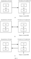
- the communication system in embodiments of this application is first described. As shown in (a) in FIG. 1 , the communication system in embodiments of this application may include a first device 101 and a second device 102. The communication system in embodiments of this application may be applied to an asymmetric transmission scenario, and may also be applied to a symmetric transmission scenario. In addition, the communication system in embodiments of this application may be applied to a wired transmission scenario and a wireless transmission scenario.
- the first device 101 in embodiments of this application may be an electronic device having sending and receiving functions or a component in the electronic device.
- the first device 101 may be an electronic device including a transmitter (Transmitter, TX) and a receiver (Receiver, RX).
- the second device 102 in embodiments of this application may be an electronic device having sending and receiving functions or a component in the electronic device.
- the second device 102 may be an electronic device including a TX and an RX.
- the first device may be a vehicle-mounted display on which a BER test needs to be performed or a chip that is in a vehicle-mounted display and on which a BER test needs to be performed
- the second device may be an external terminal apparatus configured to perform a BER test on the first device.
- the first device may alternatively be a vehicle-mounted camera on which a BER test needs to be performed or a chip that is in a vehicle-mounted camera and on which a BER test needs to be performed
- the second device may be an external terminal apparatus configured to perform a BER test on the first device.
- the first device 101 and the second device 102 in embodiments of this application may be connected through a cable.
- the second device when the communication method is performed based on the communication system, the second device mainly sends a first sequence and a second sequence to the first device, and then determines, based on a first BER that is output by the first device based on the first sequence and a second BER that is output based on the second sequence, whether the first device passes the test.
- the first device 101 shown in FIG. 1 may be understood as a device that needs to be tested, namely, a device under test, and has a BER counting function.
- the second device 102 shown in FIG. 1 may be understood as a device that tests a device under test, namely, a test device, and has a sequence sending function.
- test device in embodiments of this application may further have a sequence generation function, a sequence adjustment function, or the like.
- the first device 101 may further have a display function.
- the first device 101 may include a display, configured to display BERs obtained when BER tests are performed based on different sequences.
- the first device 101 may further have a voice broadcast function.
- the first device 101 may include a voice broadcast apparatus, configured to broadcast BERs obtained when tests are performed based on different sequences.
- a quantity of cables connected between the first device 101 and the second device 102 is not limited in embodiments of this application.
- the first device and the second device are connected through one cable, and the cable connected between the first device and the second device is used by the second device to perform unidirectional communication with the first device; or as shown in (b) in FIG. 2 , one cable connected between the first device and the second device is used for bidirectional communication between the second device and the first device.
- the first device and the second device are connected through two cables.
- a cable 1 connected between the first device and the second device is used by the second device to perform unidirectional communication with the first device
- a cable 2 connected between the first device and the second device is used by the first device to perform unidirectional communication with the second device.
- FIG. 3 is an example flowchart of the communication method according to this application. It should be understood that processes shown in FIG. 3 may be performed in various sequences and/or simultaneously. This is not limited to an execution sequence shown in FIG. 3 .
- S300 A second device sends a first sequence to a first device.
- the first sequence is used by the first device to count a first BER.
- the first sequence sent by the second device to the first device may be understood as a function test sequence.
- the function test sequence is used to perform a function test on the first device, and is usually sent before a performance test is performed on the first device.
- a small amount of data is sent in the function test sequence, and the data is mainly used to determine whether the first device has an accurate error detection and counting capability, so that it can be better ensured that a result of the performance test performed on the first device is accurate and reliable, and test time for the first device is reduced.
- the first sequence includes P subsequences A, the subsequence A is constituted by one or more forward error correction (Forward Error Correction, FEC) code blocks, and P is a positive integer.
- FEC Forward Error Correction
- the first sequence may be represented as ⁇ A, A, ..., A ⁇ , and P is a quantity of repetitions of A in the first sequence.
- a type of the FEC code block that constitutes the subsequence A and a specific structure of each type of FEC code block are not limited. Any FEC code block applicable to this embodiment of this application falls within the protection scope of embodiments of this application.
- FIG. 4 is a schematic diagram of an FEC code block according to an embodiment of this application.
- the FEC code block may include two parts.
- a first part is a data element sequence, namely, a sequence including at least one data element.
- a second part is a redundant element sequence, namely, a sequence including at least one redundant element.
- Each element is constituted by bit sequences of a same length.
- Reed-Solomon (Reed-Solomon) RS-FEC (384, 354, 9) is used as an example.
- (data element sequence i, redundant element sequence i) constitutes one RS-FEC code block
- a valid sequence in the subsequence A includes the data element sequence i
- a redundant sequence in the subsequence A includes the redundant element sequence i
- i is an integer
- i 1, ..., or L.
- S301 The first device receives the first sequence sent by the second device.
- the first device may obtain, through a cable that is connected between the first device and the second device and that is used for communication, the first sequence sent by the test equipment.
- S302 The first device counts the first BER of the received first sequence.
- This application provides a verification solution, and specific content may be as follows: First, the first sequence (which may also be referred to as the function test sequence) used to perform the function test and a first preset BER corresponding to the first sequence are determined.
- the first sequence which may also be referred to as the function test sequence
- a first preset BER corresponding to the first sequence are determined.
- the first sequence used to perform the function test may be first designed, so that the first preset BER is determined based on the first sequence.
- a value of the first preset BER may alternatively be first determined, so that the first sequence is designed based on the first preset BER.
- the second device sends the first sequence to the first device, so that the first device counts a BER of the received first sequence, to obtain the first BER.
- the performance test it may be determined, based on the first BER and the first preset BER, whether the performance test can be effectively performed on the first device. If the first BER obtained by the first device based on the received first sequence meets the first preset BER, it may be considered that the performance test can be effectively performed on the first device. Otherwise, it is considered that the performance test cannot be effectively performed on the first device.
- the second device may send the first sequence to the first device a plurality of times to perform the function test.
- a proportion namely, a pass rate
- a proportion namely, a pass rate
- the first preset BER in this embodiment of this application may be a specific value, or may be a value range.
- the first preset BER is a specific value
- the first BER is equal to the first preset BER
- the first preset BER is a specific value
- the first BER is within a floating range that is based on the first preset BER
- a left boundary of the floating range based on the first preset BER may be obtained by subtracting a first value from the first preset BER
- a right boundary of the floating range based on the first preset BER may be obtained by adding a second value to the first preset BER.
- the first value and the second value may be equal or unequal, and both are positive numbers.
- both the first value and the second value are 0.05, and the first preset BER is 10.2%.
- a range obtained based on the first preset BER is 5.2% to 15.2%.
- a left boundary of the floating range based on the first preset BER may be obtained by multiplying the first preset BER by a first proportion
- a right boundary of the floating range based on the first preset BER may be obtained by multiplying the first preset BER by a second proportion.
- the second proportion is greater than the first proportion, and both are positive numbers.
- the first proportion is 0.95
- the second proportion is 1.05
- the first preset BER is 10.2%
- a range obtained based on the first preset BER is 9.69% to 10.71%.
- the first preset BER is a value range
- the first BER is within the value range of the first preset BER
- S303 The second device sends a second sequence to the first device.
- the second sequence is used by the first device to count a second bit error rate BER.
- the second sequence sent by the second device to the first device may be understood as a performance test sequence.
- the performance test sequence is used to perform the performance test on the first device, and is generally sent after the first device passes the function test.
- a large amount of data is sent in the performance test sequence, and the data is mainly used to determine whether performance of the first device is qualified.
- the first device is a chip.
- the second device sends a performance test sequence to the chip, to determine, based on a BER result obtained by the chip through counting based on the received performance test sequence, whether the chip is a qualified chip.
- the second sequence includes Q subsequences B, the subsequence B is constituted by one or more FEC code blocks, and Q is a positive integer
- the second sequence may be represented as ⁇ B, B, ..., B ⁇ , and Q is a quantity of repetitions ofB in the second sequence.
- a type of the FEC code block that constitutes the subsequence B and a specific structure of each type of FEC code block are not limited. Any FEC code block applicable to this embodiment of this application falls within the protection scope of embodiments of this application.
- a length of the second sequence is greater than or equal to a length of the first sequence.
- Case 1 The length of the second sequence is equal to the length of the first sequence.
- a length of the subsequence B in the second sequence may be equal to a length of the subsequence A in the first sequence
- a quantity of subsequences B in the second sequence may be equal to a quantity of subsequences A in the first sequence. In this way, the length of the second sequence is equal to the length of the first sequence.
- the length of the subsequence B is 50 bits
- the length of the subsequence A is 50 bits
- the quantity of subsequences B in the second sequence is 20
- the quantity of subsequences A in the first sequence is also 20.
- a length of the subsequence B in the second sequence may be less than a length of the subsequence A in the first sequence, and a quantity of subsequences B in the second sequence may be greater than a quantity of subsequences A in the first sequence. In this way, the length of the second sequence is equal to the length of the first sequence.
- the length of the subsequence B is 40 bits
- the length of the subsequence A is 50 bits
- the quantity of subsequences B in the second sequence is 20
- the quantity of subsequences A in the first sequence is 16.
- Case 2 The length of the second sequence is greater than the length of the first sequence.
- a length of the subsequence B in the second sequence may be equal to a length of the subsequence A in the first sequence, and a quantity of subsequences B in the second sequence may be greater than a quantity of subsequences A in the first sequence. In this way, the length of the second sequence is greater than the length of the first sequence.
- the length of the subsequence B is 50 bits
- the length of the subsequence A is 50 bits
- the quantity of subsequences B in the second sequence is 30, and the quantity of subsequences A in the first sequence is 20.
- a length of the subsequence B in the second sequence may be greater than a length of the subsequence A in the first sequence, and a quantity of subsequences B in the second sequence may be equal to a quantity of subsequences A in the first sequence. In this way, the length of the second sequence is greater than the length of the first sequence.
- the length of the subsequence B is 50 bits
- the length of the subsequence A is 40 bits
- the quantity of subsequences B in the second sequence is 30, and the quantity of subsequences A in the first sequence is also 30.
- a length of the subsequence B in the second sequence may be greater than a length of the subsequence A in the first sequence, and a quantity of subsequences B in the second sequence may be greater than a quantity of subsequences A in the first sequence. In this way, the length of the second sequence is greater than the length of the first sequence.
- the length of the subsequence B is 50 bits
- the length of the subsequence A is 40 bits
- the quantity of subsequences B in the second sequence is 30, and the quantity of subsequences A in the first sequence is 20.
- the second device may send the first sequence and the second sequence to the first device together.
- S303 and S300 may be combined into one step.
- the second device may send first information to the first device, where the first information may include the first sequence and the second sequence.
- S304 The first device receives the second sequence sent by the second device.
- S305 The first device counts the second BER of the received second sequence.
- This application provides a verification solution, and specific content may be as follows: First, the second sequence (which may also be referred to as the performance test sequence) used to perform the performance test and a second preset BER corresponding to the second sequence are determined.
- the second sequence (which may also be referred to as the performance test sequence) used to perform the performance test and a second preset BER corresponding to the second sequence are determined.
- the second sequence used to perform the performance test may be first designed, so that the second preset BER is determined based on the second sequence.
- a value of the second preset BER may alternatively be first determined, so that the second sequence is designed based on the second preset BER.
- the second device sends the second sequence to the first device, so that the first device counts a BER of the received second sequence, to obtain the second BER.
- the first device may be determined, based on the second BER and the second preset BER, whether the first device passes the performance test. If the second BER obtained by the first device based on the received second sequence meets the second preset BER, it may be considered that the first device passes the performance test. Otherwise, it is considered that the first device does not pass the performance test.
- the second device may send the second sequence to the first device a plurality of times to perform the performance test.
- a proportion namely, a pass rate
- a proportion namely, a pass rate
- the second preset BER threshold in this embodiment of this application may be a specific value, or may be a value range.
- the second preset BER is a specific value
- the second BER is equal to the second preset BER
- the second preset BER is 10 ⁇ -12
- the second BER is less than 10 ⁇ -12
- the second preset BER is a value range
- the second BER is within the value range of the second preset BER
- the first sequence and the second sequence that are used to perform a BER test in an asymmetric transmission scenario in this application each are constituted by at least one FEC code block
- a design manner in which an FEC code block sequence is used as a minimum repetition unit of the first sequence and the second sequence can better adapt to a case in which the FEC code block is used for transmission in the asymmetric transmission scenario, and better facilitate BER counting performed by the first device and/or the second device.
- the first sequence in this application is constituted by P subsequences A
- the second sequence is constituted by Q subsequences B.
- the function test sequence is usually obtained by changing a value of a preset bit in the performance test sequence, and the length of the second sequence in this application is greater than or equal to the length of the first sequence. Therefore, when the length of the second sequence is greater than the length of the first sequence, time of the function test based on the first sequence can be effectively shortened, and a test speed can be improved.
- a value of a normally received bit may be set to 0, and a value of an abnormal bit may be set to 1; or a value of a normally received bit may be set to 1, and a value of an abnormal bit may be set to 0, so that during the BER test, a quantity of bits whose values are 1 or 0 may be recorded for counting.
- all bits in the second sequence are set to 0, a value of an abnormal bit in the first sequence is set to 1, and a value of a normal bit in the first sequence is 0.
- a device under test may perform BER counting by recording a quantity of special values 1 or 0 corresponding to abnormal bits.
- a counting manner is more simplified, and helps determine a BER more quickly and efficiently.
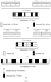
- Construction manner 1 As shown in (a) in FIG. 5 , the first sequence includes P subsequences A, each subsequence A includes N bits, and the N bits include M abnormal bits.
- P is a positive integer, and represents a quantity of subsequences A in the first sequence.
- positions of the subsequences A in the first sequence may be further represented by using 1 to P.
- a subsequence A corresponding to 1 shown in (a) in FIG. 5 may represent a subsequence A at a first position in the first sequence
- a subsequence A corresponding to 2 shown in (a) in FIG. 5 may represent a subsequence A at a second position in the first sequence
- a subsequence A corresponding to (P-1) shown in (a) in FIG. 5 may represent a subsequence A at a (P-1) th position in the first sequence
- N is a positive integer and represents a total quantity of bits included in one subsequence A.
- M is a positive integer and represents a quantity of abnormal bits included in one subsequence A. It may be understood that N is greater than or equal to M in this embodiment of this application.
- the first sequence in (a) in FIG. 5 may include five subsequences A, a total quantity of bits included in each subsequence A is 7, and there are two abnormal bits in the seven bits included in each subsequence A.
- the subsequence A is 0110111011, where 0 represents an abnormal bit, and 1 represents a normal bit.
- the first sequence may alternatively be represented as a sequence shown in (b) in FIG. 5 .
- a subsequence A(1) shown in (b) in FIG. 5 may represent a subsequence A at a first position in the first sequence, a subsequence A(2) shown in (b) in FIG.
- a subsequence A(P-1) shown in (b) in FIG. 5 may represent a subsequence A at a (P-1) th position in the first sequence
- a subsequence A(P) shown in (b) in FIG. 5 may represent a subsequence A at a P th position in the first sequence.
- the first sequence includes P subsequences A, the total quantity of bits of each subsequence A is N, and the quantity of abnormal bits is M
- a total quantity of bits included in the first sequence is a sum of total quantities of bits included in all the subsequences A in the first sequence, that is, P ⁇ N
- a quantity of abnormal bits included in the first sequence is a sum of quantities of abnormal bits included in all the subsequences A in the first sequence, that is, P ⁇ M
- a quantity of normal bits included in the first sequence is a sum of quantities of normal bits included in all the subsequences A in the first sequence, that is, (P ⁇ N-P ⁇ M). Therefore, the first sequence may be further simplified as a sequence shown in (c) in FIG. 5 .
- the first sequence includes P ⁇ N bits, and there are P ⁇ M abnormal bits in the P ⁇ N bits.
- the quantity of abnormal bits in the first sequence may be further adjusted to correspond to different first preset BERs.
- M or a ratio of M to N in the first sequence may be adjusted to correspond to different first preset BERs.
- a corresponding first preset BER is a BER 1
- a corresponding first preset BER is a BER 2
- the value of M in the subsequence A may be adjusted to M1.
- a corresponding first preset BER is a BER 3
- a corresponding first preset BER is a BER 4.
- test equipment wants to set the first preset BER to the BER 3
- the ratio of M to N in the subsequence A may be adjusted to the first ratio.
- P represents a quantity of subsequences A included in the first sequence
- N represents a total quantity of bits included in one subsequence A
- M represents a quantity of abnormal bits included in one subsequence A.
- the N bits in this embodiment of this application may be bits included in a valid sequence in the subsequence A
- the M bits in this embodiment of this application may be abnormal bits included in the valid sequence in the subsequence A.
- the subsequence A in the first sequence is a bit sequence constituted by an RS-FEC (384, 354, 9) code block, where "9" in the RS-FEC (384, 354, 9) indicates that a length of each element in the RS-FEC code block is 9 bits, "354" in the RS-FEC (384, 354, 9) indicates that a quantity of data elements included in the RS-FEC code block is 354, and "384" in RS-FEC (384, 354, 9) indicates that a total quantity of elements included in the RS-FEC code block is 384.
- the N bits in this embodiment of this application may be bits included in a valid sequence and a redundant sequence in the subsequence A
- the M bits in this embodiment of this application may be abnormal bits included in the valid sequence and the redundant sequence in the subsequence A.
- the value of the quantity M of abnormal bits in the subsequence A may be adjusted, to flexibly construct a first sequence that matches the first preset BER and that is used to perform the function test.
- the value of the quantity M of abnormal bits in the subsequence A may be adjusted, to obtain the new first sequence.
- the ratio of M to N in the subsequence A is adjusted, to flexibly construct a first sequence that matches the first preset BER and that is used to perform the function test.
- the ratio of M to N in the subsequence A may be adjusted, to obtain the new first sequence.
- the first sequence includes P subsequences A, each subsequence A includes X first FEC code blocks and Y second FEC code blocks, all bits in a data element sequence of the first FEC code block are normal bits, and all bits in a data element sequence of the second FEC code block are abnormal bits.
- P is a positive integer, and represents a quantity of subsequences A in the first sequence.
- positions of the subsequences A in the first sequence may be further represented by using 1 to P.
- X is a positive integer, and represents a quantity of first FEC code blocks included in one subsequence A.
- Y is a positive integer, and represents a quantity of second FEC code blocks included in one subsequence A.
- the first sequence in FIG. 6 may include five subsequences A, and each subsequence A includes three first FEC code blocks and two second FEC code blocks.
- positions of the first sequence and the second sequence shown in FIG. 6 are merely an example.
- positions of the first FEC code blocks and the second FEC code blocks in the subsequence A are not limited, and the first FEC code blocks and the second FEC code blocks may be randomly arranged.
- the subsequence A includes X first FEC code blocks and Y second FEC code blocks
- one first FEC code block and one second FEC code block are minimum repetition units in the first sequence.
- a length of the first FEC code block in this embodiment of this application may be the same as a length of the second FEC code block.
- the first FEC code block and the second FEC code block each are constituted by the RS-FEC (384, 354, 9) code block whose length is 3456 bits, where 0 represents an abnormal bit, and 1 represents a normal bit.
- all the bits in the data element sequence of the first FEC code block are 1, and all the bits in the data element sequence of the second FEC code block are 0.
- the subsequence A includes three first FEC code blocks (a1 for short for ease of description) and one second FEC code block (a2 for short for ease of description), and the subsequence A may be represented as a1, a1, a2, and a1.
- the first sequence may be represented as a1, a1, a2, a1, a1, a1, a2, a1.
- lengths of the first FEC code block and the second FEC code block are 3456 bits
- the subsequence A includes three first FEC code blocks and one second FEC code block
- a quantity of abnormal bits included in the subsequence A is 3456.
- the first sequence includes two subsequences A
- FEC code blocks in the first sequence may be further adjusted to correspond to different first preset BERs.
- a value of Y or a ratio of Y to (X+Y) in the first sequence may be adjusted to correspond to different first preset BERs.
- a corresponding first preset BER is a BER 1
- a corresponding first preset BER is a BER 2
- test equipment wants to set the first preset BER to the BER 1
- the value of Y in the subsequence A may be adjusted to Y1.
- a corresponding first preset BER is a BER 3
- a corresponding first preset BER is a BER 4
- the ratio of Y to (X+Y) in the subsequence A may be adjusted to the first ratio.
- X represents a quantity of first FEC code blocks included in one subsequence A
- Y represents a quantity of second FEC code blocks included in one subsequence A.
- all the bits included in the data element sequence of the first FEC code block may be set to normal bits, and all the bits included in the data element sequence of the second FEC code block may be set to abnormal bits.
- the subsequence A in the first sequence includes 963 first FEC code blocks, that is, a value of X is 963, and all the bits in the data element sequence in the first FEC code block are normal bits; and the subsequence A includes 37 second FEC code blocks, that is, the value of Y is 37, and all the bits in the data element sequence in the second FEC code block are abnormal bits.
- a length of the data element sequence of the first FEC code block is consistent with a length of the data element sequence of the second FEC code block.
- all bits included in the data element sequence and a redundant element sequence of the first FEC code block may be set to normal bits, and all bits included in the data element sequence and a redundant element sequence of the second FEC code block may be set to abnormal bits.
- the subsequence A in the first sequence includes 963 first FEC code blocks, that is, a value of X is 963, and all the bits in the data element sequence and the redundant element sequence in the first FEC code block are normal bits; and the subsequence A includes 37 second FEC code blocks, that is, the value of Y is 37, and all the bits in the data element sequence and the redundant element sequence in the second FEC code block are abnormal bits.
- all bits included in the second FEC code block are set to abnormal bits, and it may be obtained that the first preset BER can be more conveniently adjusted, and a calculation process of determining the first preset BER is simplified.
- the first sequence includes P subsequences A, and each subsequence A includes X first FEC code blocks and Y second FEC code blocks. All bits in a data element sequence of the first FEC code block are normal bits; and abnormal bits of a fixed quantity exist in a data element sequence of the second FEC code block, or abnormal bits of a fixed proportion exist in a data element sequence of the second FEC code block.
- the first FEC code block and the second FEC code block each are constituted by the RS-FEC (384, 354, 9) code block whose length is 3456 bits, all bits in the data element sequence of the first FEC code block are 1, and abnormal bits of a fixed quantity 5 exist in the data element sequence of the second FEC code block.
- the second FEC code block may be 111... 1000001, 111... 1010000, 111... 0001001, or the like. In other words, it is ensured that the quantity of abnormal bits in the data element sequence of the second FEC code block is 5.
- the subsequence A includes three first FEC code blocks (a1 for short for ease of description) and one second FEC code block (a3 for short for ease of description), and the subsequence A may be represented as a1, a3, a1, and a1.
- the first sequence may be represented as a1, a3, a1, a1, a1, a3, a1, a1.
- lengths of the first FEC code block and the second FEC code block are 3456 bits
- the quantity of second FEC code blocks in the first sequence may be further adjusted to correspond to different first preset BERs.
- a value of Y or a ratio of Y to (X+Y) in the first sequence may be adjusted to correspond to different first preset BERs.
- a corresponding first preset BER is a BER 1
- a corresponding first preset BER is a BER 2
- test equipment wants to set the first preset BER to the BER 1
- the value of Y in the subsequence A may be adjusted to Y1.
- a corresponding first preset BER is a BER 3
- a corresponding first preset BER is a BER 4
- the ratio of Y to (X+Y) in the subsequence A may be adjusted to the first ratio.
- X represents a quantity of first FEC code blocks included in one subsequence A
- T represents a proportion of abnormal bits in the first FEC code block
- Y represents a quantity of second FEC code blocks included in one subsequence A.
- all the bits included in the data element sequence of the first FEC code block may be set to normal bits, and the bits of the fixed quantity or the fixed proportion that are included in the data element sequence of the second FEC code block may be set to abnormal bits.
- the subsequence A in the first sequence includes 963 first FEC code blocks, that is, a value of X is 963, and all the bits in the data element sequence in the first FEC code block are normal bits; and the subsequence A includes 74 second FEC code blocks, that is, the value of Y is 74, and 50% of bits in the data element sequence in the second FEC code block are abnormal bits.
- a length of the data element sequence of the first FEC code block is consistent with a length of the data element sequence of the second FEC code block.
- all bits included in the data element sequence and a redundant element sequence of the first FEC code block may be set to normal bits, and bits of a fixed quantity or a fixed proportion that are included in the data element sequence and a redundant element sequence of the second FEC code block may be set to abnormal bits.
- the subsequence A in the first sequence includes 963 first FEC code blocks, that is, a value of X is 963, and all the bits in the data element sequence and the redundant element sequence in the first FEC code block are normal bits; and the subsequence A includes 74 second FEC code blocks, that is, the value of Y is 74, and the quantity of abnormal bits in the second FEC code blocks accounts for 50% of a total quantity of bits in the data element sequence and the redundant element sequence.
- the value of Y in the subsequence A may be adjusted, to flexibly construct a first sequence that matches the first preset BER and that is used to perform the function test.
- the value of Y in the subsequence A may be adjusted, to obtain the new first sequence.
- the ratio of Y to (X+Y) in the subsequence A is adjusted, to flexibly construct a first sequence that matches the first preset BER and that is used to perform the function test.
- the ratio of Y to (X+Y) in the subsequence A may be adjusted, to obtain the new first sequence.
- the second FEC code block in the construction manner 3 may also be referred to as an uncorrectable FEC code block, and is a sequence having a length equal to that of the first FEC code block.
- a quantity of error elements in the second FEC code block exceeds an upper limit of error-correctable elements of the FEC code block.
- the RS-FEC (384, 354, 9) is used as one FEC code block.
- 354 correct valid data elements cannot be recovered through RS-FEC decoding correction.
- all bits in the RS-FEC code block are replaced with error elements, where 1 represents the error element.
- Scenario 1 The second device sends the first sequence and the second sequence together to the first device.
- S800 The second device sends the first sequence and the second sequence to the first device.
- S801 The first device receives the first sequence and the second sequence from the second device.
- S802 The first device counts the first BER of the received first sequence.
- S803 The first device determines whether the first BER meets the first preset BER, where if the first BER meets the first preset BER, S804 is performed; or if the first BER does not meet the first preset BER, S805 is performed.
- test personnel may determine, based on the first BER output by the first device, whether the first BER obtained by the first device meets the first preset BER; or the first device may transmit the first BER back to the second device, and the second device determines whether the first BER meets the first preset BER, and then notifies the first device or the test personnel of a determining result.
- S804 The first device counts the second BER of the received second sequence.
- the first device may output the second BER, so that the test personnel determine, based on the second BER, whether the first device passes the performance test.
- test personnel determine that the second BER does not meet the second preset BER, it is determined that the first device does not pass the performance test; or if the test personnel determine that the second BER meets the second preset BER, it is determined that the first device passes the performance test.
- S805 The first device terminates a subsequent test performed based on the received second sequence.
- the first device may prompt, by using a voice, the test personnel that the first device does not pass the function test.
- Scenario 2 After the first BER meets the first preset BER, the second device is triggered to send the second sequence to the first device.
- S900 The second device sends the first sequence to the first device.
- S901 The first device receives the first sequence from the second device.
- S902 The first device counts the first BER of the received first sequence.
- S903 The first device transmits the first BER back to the second device.
- S904 The second device determines whether the first BER meets the first preset BER, where if the first BER meets the first preset BER, S905 is performed; or if the first BER does not meet the first preset BER, S906 is performed.
- test personnel may determine, based on the first BER output by the first device, whether the first BER obtained by the first device meets the first preset BER.
- S903 and S904 may be optional steps, and do not constitute a limitation on this embodiment of this application.
- the test personnel may determine, based on the first BER output by the first device, whether the first BER obtained by the first device meets the first preset BER. In this case, steps S903 and S904 may be omitted.
- S905 The second device sends the second sequence to the first device, and continues to perform S907.
- the test personnel may trigger the second device to send the second sequence to the first device.
- the test personnel may determine, based on the first BER output by the first device, whether the first BER obtained by the first device meets the first preset BER, and when determining that the first BER meets the first preset BER, trigger the second device to send the second sequence to the first device.
- the second device may automatically trigger sending of the second sequence to the first device.
- the first device transmits the first BER back to the second device, and the second device determines whether the first BER meets the first preset BER, and when determining that the first BER meets the first preset BER, the second device triggers the second device to send the second sequence to the first device.
- the second device may prompt, by using a voice, the test personnel that the device under test (namely, the first device) passes the function test.
- S906 The second device determines to terminate a subsequent test performed based on the second sequence.
- the test personnel may trigger the second device to terminate the subsequent test performed based on the second sequence.
- the test personnel may determine, based on the first BER output by the first device, whether the first BER obtained by the first device meets the first preset BER, and when determining that the first BER does not meet the first preset BER, trigger the second device to terminate the subsequent test performed based on the second sequence.
- the second device may automatically trigger termination of the subsequent test performed based on the second sequence.
- the first device transmits the first BER back to the second device, and the second device determines whether the first BER meets the first preset BER, and when determining that the first BER does not meet the first preset BER, the second device triggers termination of the subsequent test performed based on the second sequence.
- the second device may prompt, by using a voice, the test personnel that the device under test (namely, the first device) does not pass the function test.
- S907 The first device counts the second BER of the received second sequence.
- the first device may output the second BER, so that the test personnel determine, based on the second BER, whether the first device passes the performance test.
- test personnel determine that the second BER does not meet the second preset BER, it is determined that the first device does not pass the performance test; or if the test personnel determine that the second BER meets the second preset BER, it is determined that the first device passes the performance test.
- the first sequence may be sent to the first device a plurality of times to perform a test.
- the function test is performed on the first device a plurality of times.
- the first sequence sent each time may be the same or may be different. This is not specifically limited in this embodiment of this application.
- the second sequence test is performed on the first device.
- the performance test is performed on the first device.
- the threshold proportion is 80%
- the total quantity of performing the function test on the first device is 10
- the quantity of times that the first device passes the function test is 9, and a pass rate is 90%, which is greater than the threshold proportion 80%.
- the second device may further send at least one training sequence to the first device, and perform receive link training with the first device by using the training sequence, so that receive parameters of the first device converge. In this way, in a subsequent test process, the test process is smoother and more stable.
- the methods and the apparatuses are conceived based on a same or similar technical concept.
- the methods and the apparatuses have similar principles for resolving the problems. Therefore, for implementations of the apparatuses and the methods, refer to each other. Details of repeated parts are not described.
- the term "apparatus” and “device” may be used interchangeably in embodiments of this application.
- the term “and/or” describes an association relationship between associated objects and indicates that three relationships may exist.
- a and/or B may indicate the following three cases: Only A exists, both A and B exist, and only B exists.
- the character “/” generally represents an “or” relationship between the associated objects.
- at least one means one or more, and "a plurality of" means two or more.
- FIG. 10 is a schematic block diagram of an apparatus 1000 according to an embodiment of this application.
- the apparatus 1000 is configured to implement functions of the first device or the second device in the method embodiments.
- the apparatus may be a software module or a chip system.
- the chip may include a chip, or may include a chip and another discrete component.
- the apparatus 1000 includes a processing unit 1001 and a communication unit 1002.
- the communication unit 1002 is configured to communicate with another device, and may also be referred to as a communication interface, a transceiver unit, an input/output interface, or the like.
- the apparatus 1000 may be the first device, or a chip, a circuit, or the like configured in the first device.
- the processing unit 1001 may be configured to perform a processing-related operation of the first device in the method embodiments.
- the communication unit 1002 is configured to perform receiving and sending-related operations of the first device in the method embodiments.
- the communication unit 1002 in this embodiment of this application may be a receiving unit.
- the communication unit 1002 is configured to receive a first sequence sent by the second device, where the first sequence includes P subsequences A, and the subsequence A is constituted by one or more forward error correction FEC code blocks; the processing unit 1001 is configured to count a first BER of the received first sequence; the communication unit 1002 is configured to receive a second sequence sent by the second device, where the second sequence includes Q subsequences B, and the subsequence B is constituted by one or more forward error correction FEC code blocks; and the processing unit 1001 is configured to count a second BER of the received second sequence, where a length of the second sequence is greater than or equal to a length of the first sequence, and P and Q are positive integers.
- the processing unit 1001 is further configured to: when the first BER meets a first preset BER, count the second BER of the received second sequence.
- the processing unit 1001 is specifically configured to: count a quantity of abnormal bits in the received first sequence, or count a ratio of a quantity of abnormal bits in the received first sequence to a total quantity of bits in the received first sequence.
- the processing unit 1001 is specifically configured to: count a quantity of abnormal bits in the received second sequence, or count a ratio of a quantity of abnormal bits in the received second sequence to a total quantity of bits in the received second sequence.
- the subsequence A includes N bits; the subsequence A includes M abnormal bits; and M or a ratio of M to N corresponds to the first preset BER, where N and M are positive integers, and N is greater than or equal to M.
- the N bits are bits included in a valid sequence in the subsequence A, and the M bits are abnormal bits included in the valid sequence in the subsequence A; or the N bits are bits included in a valid sequence and a redundant sequence in the subsequence A, and the M bits are abnormal bits included in the valid sequence and the redundant sequence in the subsequence A.
- Each of the one or more FEC code blocks includes a data element sequence and a redundant element sequence
- the valid sequence in the subsequence A includes the data element sequence of the one or more FEC code blocks
- the redundant sequence in the subsequence A includes the redundant element sequence of the one or more FEC code blocks.
- the subsequence A includes X first FEC code blocks and Y second FEC code blocks; all bits included in a data element sequence of the first FEC code block are normal bits; a data element sequence of the second FEC code block includes abnormal bits of a fixed quantity or abnormal bits of a fixed proportion; and Y or a ratio of Y to (X+Y) corresponds to the first preset BER, where X and Y are positive integers.
- all bits included in the data element sequence of the second FEC code block are abnormal bits.
- all bits included in a redundant element sequence of the first FEC code block are normal bits, and all bits included in a redundant element sequence of the second FEC code block are abnormal bits.
- a length of the subsequence A is equal to a length of the subsequence B.
- all bits included in the first FEC code block may be 0, all abnormal bits of a fixed quantity or a fixed proportion in the second FEC code block are 1, and all remaining bits are 0.
- the processing unit 1001 before sending the first sequence to the first device, the processing unit 1001 is further configured to perform link training with the first device.
- the apparatus 1000 may be the second device, or a chip, a circuit, or the like configured in the second device.
- the processing unit 1001 may be configured to perform a processing-related operation of the second device in the method embodiments.
- the communication unit 1002 may be configured to perform receiving and sending-related operations of the second device in the method embodiments.
- the communication unit 1002 in this embodiment of this application may be a sending unit.
- the communication unit 1002 is configured to: send a first sequence to the first device, where the first sequence is used by the first device to count a first bit error rate BER, the first sequence includes P subsequences A, and the subsequence A is constituted by one or more forward error correction FEC code blocks; and send a second sequence to the first device, where the second sequence is used by the first device to count a second BER, the second sequence includes Q subsequences B, the subsequence B is constituted by one or more forward error correction FEC code blocks, a length of the second sequence is greater than or equal to a length of the first sequence, and P and Q are positive integers.
- the first BER is obtained by recording a quantity of abnormal bits in the first sequence
- the second BER is obtained by recording a quantity of abnormal bits in the second sequence.
- the communication unit 1002 is specifically configured to: when the first BER meets a first preset BER, send the second sequence to the first device.
- the subsequence A includes N bits; the subsequence A includes M abnormal bits; and M or a ratio of M to N corresponds to the first preset BER, where N and M are positive integers, and N is greater than or equal to M.
- the N bits are bits included in a valid sequence in the subsequence A, and the M bits are abnormal bits included in the valid sequence in the subsequence A; or the N bits are bits included in a valid sequence and a redundant sequence in the subsequence A, and the M bits are abnormal bits included in the valid sequence and the redundant sequence in the subsequence A.
- Each of the one or more FEC code blocks includes a data element sequence and a redundant element sequence
- the valid sequence in the subsequence A includes the data element sequence of the one or more FEC code blocks
- the redundant sequence in the subsequence A includes the redundant element sequence of the one or more FEC code blocks.
- the subsequence A includes X first FEC code blocks and Y second FEC code blocks; all bits included in a data element sequence of the first FEC code block are normal bits; a data element sequence of the second FEC code block includes abnormal bits of a fixed quantity or abnormal bits of a fixed proportion; and Y or a ratio of Y to (X+Y) corresponds to the first preset BER, where X and Y are positive integers.
- all bits included in the data element sequence of the second FEC code block are abnormal bits.
- all bits included in a redundant element sequence of the first FEC code block are normal bits, and all bits included in a redundant element sequence of the second FEC code block are abnormal bits.
- a length of the subsequence A is equal to a length of the subsequence B.
- all bits included in the first FEC code block may be 0, all abnormal bits of a fixed quantity or a fixed proportion in the second FEC code block are 1, and all remaining bits are 0.
- the processing unit 1001 before sending the first sequence to the first device, the processing unit 1001 is further configured to perform link training with the first device.
- division into the units is an example, and is merely logical function division. In an actual implementation, another division manner may be used.
- the functional units in this embodiment of this application may be integrated into one processor, or each of the units may exist alone physically, or two or more units are integrated into one unit.
- the integrated unit may be implemented in a form of hardware, or may be implemented in a form of a software functional unit.
- FIG. 11 is a schematic diagram of an apparatus 1100 according to an embodiment of this application.
- the apparatus 1100 may be an electronic apparatus or a component in an electronic apparatus, for example, a chip or an integrated circuit.
- the apparatus 1100 may include at least one processor 1102 and a communication interface 1104. Further, optionally, the apparatus may further include at least one memory 1101. Further, optionally, a bus 1103 may be further included.
- the memory 1101, the processor 1102, and the communication interface 1104 are connected through the bus 1103.
- the memory 1101 is configured to provide storage space, and the storage space may store data such as an operating system and a computer program.
- the memory 1101 mentioned in this embodiment of this application may be a volatile memory or a non-volatile memory, or may include a volatile memory and a non-volatile memory.
- the non-volatile memory may be a read-only memory (read-only memory, ROM), a programmable read-only memory (programmable ROM, PROM), an erasable programmable read-only memory (erasable PROM, EPROM), an electrically erasable programmable read-only memory (electrically EPROM, EEPROM), or a flash memory.
- the volatile memory may be a random access memory (random access memory, RAM), and used as an external cache.
- RAMs may be used, for example, a static random access memory (static RAM, SRAM), a dynamic random access memory (dynamic RAM, DRAM), a synchronous dynamic random access memory (synchronous DRAM, SDRAM), a double data rate synchronous dynamic random access memory (double data rate SDRAM, DDR SDRAM), an enhanced synchronous dynamic random access memory (enhanced SDRAM, ESDRAM), a synchronous link dynamic random access memory (synchlink DRAM, SLDRAM), and a direct rambus dynamic random access memory (direct rambus RAM, DR RAM).
- static random access memory static random access memory
- DRAM dynamic random access memory
- DRAM dynamic random access memory
- SDRAM synchronous dynamic random access memory
- double data rate SDRAM double data rate SDRAM
- DDR SDRAM double data rate SDRAM
- ESDRAM enhanced synchronous dynamic random access memory
- SLDRAM synchronous link dynamic random access memory
- direct rambus RAM direct rambus RAM
- the processor 1102 is a module for performing an arithmetic operation and/or a logical operation, and may be specifically one or a combination of a plurality of processing modules such as a central processing unit (central processing unit, CPU), a graphics processing unit (graphics processing unit, GPU), a microprocessor (microprocessor unit, MPU), an application-specific integrated circuit (application-specific integrated circuit, ASIC), a field programmable gate array (field programmable gate array, FPGA), a complex programmable logic device (complex programmable logic device, CPLD), a synergistic processing unit (assisting the central processing unit to complete corresponding processing and application), and a microcontroller unit (microcontroller unit, MCU).
- a central processing unit central processing unit, CPU
- graphics processing unit graphics processing unit
- MPU microprocessor
- ASIC application-specific integrated circuit
- FPGA field programmable gate array
- FPGA field programmable gate array
- CPLD complex programmable logic device
- synergistic processing unit
- the processor is a general-purpose processor, an ASIC, an FPGA, or another programmable logic device, a discrete gate or a transistor logic device, or a discrete hardware component
- the memory may be integrated into the processor
- the communication interface 1104 may be configured to provide an information input or output for the at least one processor, and/or the communication interface may be configured to receive data sent from the outside and/or send data to the outside, and may be a wired link interface including an Ethernet cable or the like, or may be a wireless link (Wi-Fi, Bluetooth, universal wireless transmission, a vehicle-mounted short-range communication technology, or the like) interface.
- the communication interface 1104 may further include a transmitter (for example, a radio frequency transmitter or an antenna), a receiver, or the like coupled to the interface.
- the apparatus 1100 may be the first device or a component in the first device in the method embodiments, for example, a chip or an integrated circuit.
- the processor 1102 in the apparatus 1100 is configured to read the computer program stored in the memory 1101, to control the first device to perform the following operations: sending a first sequence to a first device, where the first sequence is used by the first device to count a first BER, the first sequence includes P subsequences A, and the subsequence A is constituted by one or more forward error correction FEC code blocks; and sending a second sequence to the first device, where the second sequence is used by the first device to count a second BER, the second sequence includes Q subsequences B, the subsequence B is constituted by one or more forward error correction FEC code blocks, a length of the second sequence is greater than or equal to a length of the first sequence, and P and Q are positive integers.
- the processor 1102 in the first device may be further configured to read the program in the memory 1101 and perform the method procedure performed by the test equipment in S300 to S305 shown in FIG. 3 ; or may be further configured to read the program in the memory 1101 and perform the method procedure performed by the test equipment in S800 to S805 shown in FIG. 8 ; or may be further configured to read the program in the memory 1101 and perform the method procedure performed by the test equipment in S900 to S907 shown in FIG. 9 .
- the apparatus 1100 may be the second device or a component in the second device in the method embodiments, for example, a chip or an integrated circuit.
- the processor 1102 in the apparatus 1100 is configured to read the computer program stored in the memory 1101, to control the second device to perform the following operations: receiving a first sequence sent by a second device, where the first sequence includes P subsequences A, and the subsequence A is constituted by one or more forward error correction FEC code blocks; counting a first bit error rate BER of the received first sequence; receiving a second sequence sent by the second device, where the second sequence includes Q subsequences B, and the subsequence B is constituted by one or more forward error correction FEC code blocks; and counting a second BER of the received second sequence, where a length of the second sequence is greater than or equal to a length of the first sequence, and P and Q are positive integers.
- the processor 1102 in the second device may be further configured to read the program in the memory 1101 and perform the method procedure performed by the device under test in S300 to S305 shown in FIG. 3 ; or may be further configured to read the program in the memory 1101 and perform the method procedure performed by the device under test in S800 to S805 shown in FIG. 8 ; or may be further configured to read the program in the memory 1101 and perform the method procedure performed by the device under test in S900 to S907 shown in FIG. 9 .
- An embodiment of this application further provides a computer-readable storage medium (including but not limited to a magnetic disk memory, a CD-ROM, an optical memory, and the like), including instructions.
- a computer-readable storage medium including but not limited to a magnetic disk memory, a CD-ROM, an optical memory, and the like.
- An embodiment of this application further provides a chip system.
- the chip system includes at least one processor and an interface circuit. Further, optionally, the chip system may further include a memory or an external memory.
- the processor is configured to execute instructions and/or data interaction through the interface circuit, to implement the method in the foregoing method embodiments.
- the chip system may include a chip, or may include a chip and another discrete component.
- An embodiment of this application further provides a computer program product, including instructions.
- the instructions When the instructions are run on a computer, the computer is enabled to perform the method described in the foregoing embodiments.
- All or some of the methods in embodiments of this application may be implemented by using software, hardware, firmware, or any combination thereof.
- software is used to implement the embodiments, all or some of the embodiments may be implemented in a form of a computer program product.
- the computer program product includes one or more computer instructions. When the computer program instructions are loaded and executed on a computer, the procedure or functions according to embodiments of this application are all or partially generated.
- the units described as separate parts may or may not be physically separate, and parts displayed as units may or may not be physical units, may be located in one position, or may be distributed on a plurality of network units. Some or all of the units may be selected based on an actual requirement to achieve the objectives of the solutions of embodiments.
Landscapes
- Engineering & Computer Science (AREA)
- Computer Networks & Wireless Communication (AREA)
- Signal Processing (AREA)
- Quality & Reliability (AREA)
- Detection And Prevention Of Errors In Transmission (AREA)
Abstract
Description
- Embodiments of this application relate to the field of communication technologies, and in particular, to a communication method, apparatus, and system.
- Performance of a transmission chip is critical to a data transmission rate. Therefore, the performance of the transmission chip needs to be tested frequently. A bit error rate (bit error rate, BER) is an important index of the transmission chip. A BER test may be performed on the transmission chip to verify whether the transmission chip reaches a specified BER index.
- During actual application, there is often an asymmetric transmission scenario in which an uplink rate is not equal to a downlink rate. For example, in a vehicle-mounted high-definition camera, an uplink rate (in an output direction of image data of the camera) of a transmission chip usually reaches 1 Gbps to 10 Gbps, but a downlink rate is usually only 1 Mbps to 100 Mbps.
- Therefore, how to design a BER test method for a transmission chip in the asymmetric transmission scenario is an urgent problem to be resolved.
- This application provides a communication method, apparatus, and system, to perform a BER test on a transmission chip in an asymmetric transmission scenario.
- The communication method provided in this application may be performed by a second device. The second device may be used as test equipment (Test Equipment, TE). The second device may be abstracted as a computer system. The second device may be an entire system, or may be a part of components in an entire system, for example, a system chip or a processing chip. The system chip may also include a system on chip (system on chip, SOC) or an SoC chip. Specifically, the second device may be an independent apparatus configured to perform a BER test on a device under test, or the second device may be a component configured to perform a BER test on a device under test in an entire system. For example, the second device may be a terminal apparatus or a vehicle-mounted device like a vehicle-mounted computer or a head unit that has a BER test function, or may be a system chip, a decision processing chip, or another type of chip that can be disposed in a computer system of a vehicle or a vehicle-mounted device and that has a BER test function.
- According to a first aspect, an embodiment of this application provides a communication method, including:
sending a first sequence to a first device, where the first sequence is used by the first device to count a first bit error rate BER, the first sequence includes P subsequences A, and the subsequence A is constituted by one or more forward error correction FEC code blocks; and sending a second sequence to the first device, where the second sequence is used by the first device to count a second BER, the second sequence includes Q subsequences B, the subsequence B is constituted by one or more forward error correction FEC code blocks, a length of the second sequence is greater than or equal to a length of the first sequence, and P and Q are positive integers. - In an example, in an asymmetric transmission scenario, when the method is performed by a second device, the first sequence and the second sequence may be separately sent. For example, the second device may first send the first sequence to the first device, and then send the second sequence to the first device.
- In another example, in an asymmetric transmission scenario, when the method is performed by a second device, the first sequence and the second sequence may be sent at the same time. For example, the second device sends first information to the first device, where the first information includes the first sequence and the second sequence.
- According to the method, in a BER test in this application, an FEC code block used by a device for transmission is effectively used as a minimum repetition unit of the first sequence and the second sequence, so that complexity of constructing a test sequence by the device is reduced, and robustness of a test process is improved. Further, when the length of the second sequence is greater than the length of the first sequence, time of a function test based on the first sequence can be effectively shortened, and a test speed can be improved. In the asymmetric transmission scenario, this method can be used to perform a unidirectional BER test. This can simplify a test process and test time, and improve test efficiency. It may be understood that this test method may also be applied to a symmetric transmission scenario.
- In a possible design, when the first BER meets a first preset BER, the second sequence is sent to the first device.
- In an example, the first preset BER may be a specific value. When the first preset BER is a specific value, and the first BER is equal to the first preset BER, it is determined that the first BER meets the first preset BER. Alternatively, when the first preset BER is a specific value, and the first BER is within a floating range that is based on the first preset BER, it is determined that the first BER meets the first preset BER. For example, a left boundary of the floating range based on the first preset BER may be obtained by subtracting a first value from the first preset BER, and a right boundary of the floating range based on the first preset BER may be obtained by adding a second value to the first preset BER. The first value and the second value may be equal or unequal, and both are positive numbers. For another example, a left boundary of the floating range based on the first preset BER may be obtained by multiplying the first preset BER by a first proportion, and a right boundary of the floating range based on the first preset BER may be obtained by multiplying the first preset BER by a second proportion. The second proportion is greater than the first proportion, and both are positive numbers.
- In an example, the first preset BER may alternatively be a value range. When the first preset BER is a value range, and the first BER is within the value range of the first preset BER, it is determined that the first BER meets the first preset BER.
- It may be understood that in the method, a case in which the second device is triggered to send the second sequence to the first device in the asymmetric transmission scenario is provided. For example, when it is determined that the first BER obtained by the first device through counting based on the received first sequence meets the first preset BER, it is considered that the first device has an accurate error detection and counting capability, so that it can be better ensured that a result of a subsequent performance test performed by the first device based on the second sequence is accurate and reliable. Therefore, the second device may be triggered to send the second sequence to the first device.
- In this application, when it is determined whether the first BER counted by the first device based on the received first sequence meets the first preset BER, test personnel may manually determine whether the first BER counted by the first device based on the received first sequence meets the first preset BER. When determining that the first BER meets the first preset BER, the test personnel manually trigger the second device to send the second sequence to the first device. Alternatively, in this application, when it is determined whether the first BER counted by the first device based on the received first sequence meets the first preset BER, after the first device obtains the first BER through counting based on the received first sequence, the first device may transmit the first BER back to the second device, so that the second device determines whether the received first BER meets the first preset BER. When determining that the first BER meets the first preset BER, the second device is triggered to send the second sequence to the first device. In a possible design, the subsequence A includes N bits; the subsequence A includes M abnormal bits; and M or a ratio of M to N corresponds to the first preset BER, where N and M are positive integers, and N is greater than or equal to M. Therefore, this application provides a constitution manner of the subsequence A.
- It may be understood that in this embodiment of this application, that M corresponds to the first preset BER means that when different first preset BERs need to be met, test equipment may flexibly set the first preset BER by adjusting a value of M in the subsequence A. For example, when the value of M in the subsequence A is M1, a corresponding first preset BER is a
BER 1; and when the value of M in the subsequence A is M2, a corresponding first preset BER is aBER 2. When the test equipment wants to set the first preset BER to theBER 1, the value of M in the subsequence A may be adjusted to M1. - In this embodiment of this application, that a ratio of M to N corresponds to the first preset BER means that when different first preset BERs need to be met, the test equipment may flexibly set the first preset BER by adjusting the ratio of M to N in the subsequence A. For example, when the ratio of M to N in the subsequence A is a first ratio, a corresponding first preset BER is a BER 3; and when the ratio of M to N in the subsequence A is a second ratio, a corresponding first preset BER is a BER 4. When the test equipment wants to set the first preset BER to the BER 3, the ratio of M to N in the subsequence A may be adjusted to the first ratio.
- According to the method, in this application, when the BER test is performed in the asymmetric transmission scenario, for example, in a scenario in which the BER test is performed on a transmission chip in a vehicle-mounted high-definition camera, the second device does not need an additional circuit to perform encoding to generate the first sequence, and may generate the first sequence based on one or more stored FEC units, so that a case in which an FEC code block is used for transmission in the asymmetric transmission scenario can be better adapted. In this application, when the first preset BER needs to be adjusted, in one manner, the value of the quantity M of abnormal bits in the subsequence A may be adjusted, to flexibly construct a first sequence that matches the first preset BER and that is used to perform a function test. Alternatively, when a new first sequence needs to be set in this application, the value of the quantity M of abnormal bits in the subsequence A may be adjusted, to obtain the new first sequence. In this application, when the first preset BER needs to be adjusted, in another manner, the ratio of M to N in the subsequence A is adjusted, to flexibly construct a first sequence that matches the first preset BER and that is used to perform a function test. Alternatively, when a new first sequence needs to be set in this application, the ratio of M to N in the subsequence A may be adjusted, to obtain the new first sequence.
- In a possible design, the N bits are bits included in a valid sequence in the subsequence A, and the M bits are abnormal bits included in the valid sequence in the subsequence A; or the N bits are bits included in a valid sequence and a redundant sequence in the subsequence A, and the M bits are abnormal bits included in the valid sequence and the redundant sequence in the subsequence A. Each of the one or more FEC code blocks includes a data element sequence and a redundant element sequence, the valid sequence in the subsequence A includes the data element sequence of the one or more FEC code blocks, and the redundant sequence in the subsequence A includes the redundant element sequence of the one or more FEC code blocks.
- It may be understood that bits included in the valid sequence in the subsequence A in this application are bits included in data element sequences in all the FEC code blocks that constitute the subsequence A. Bits included in the redundant sequence in the subsequence A in this application are bits included in redundant element sequences in all the FEC code blocks that constitute the subsequence A.
- In an example, in the asymmetric transmission scenario in this application, when counting the first BER based on the first sequence, the first device may count only data element sequences in FEC code blocks that constitute the first sequence. Therefore, when the first preset BER is designed, only the data element sequences in the FEC code blocks that constitute the first sequence may be considered. For example, in this case, the N bits corresponding to the first preset BER are bits included in the valid sequence in the subsequence A, and the M bits are abnormal bits included in the valid sequence in the subsequence A.
- In another example, in the asymmetric transmission scenario in this application, when counting the first BER based on the first sequence, the first device may alternatively consider all elements in FEC code blocks that constitute the first sequence, namely, data element sequences and redundant element sequences. Therefore, when the first preset BER is designed, all the elements in the FEC code blocks that constitute the first sequence may be considered. For example, in this case, the N bits corresponding to the first preset BER are bits included in the valid sequence and the redundant sequence in the subsequence A, and the M bits are abnormal bits included in the valid sequence and the redundant sequence in the subsequence A.
- In a possible design, the subsequence A includes X first FEC code blocks and Y second FEC code blocks; all bits included in a data element sequence of the first FEC code block are normal bits; a data element sequence of the second FEC code block includes abnormal bits of a fixed quantity or abnormal bits of a fixed proportion; and Y or a ratio of Y to (X+Y) corresponds to the first preset BER, where X and Y are positive integers. Therefore, this application provides another constitution manner of the subsequence A.
- It may be understood that in this embodiment of this application, that Y corresponds to the first preset BER means that when different first preset BERs need to be met, test equipment may flexibly set the first preset BER by adjusting a value of Y in the subsequence A. For example, when the value of Y in the subsequence A is Y1, a corresponding first preset BER is a
BER 1; and when the value of Y in the subsequence A is Y2, a corresponding first preset BER is aBER 2. When the test equipment wants to set the first preset BER to theBER 1, the value of Y in the subsequence A may be adjusted to Y1. - In this embodiment of this application, that a ratio of Y to (X+Y) corresponds to the first preset BER means that when different first preset BERs need to be met, the test equipment may flexibly set the first preset BER by adjusting the ratio of Y to (X+Y) in the subsequence A. For example, when the ratio of Y to (X+Y) in the subsequence A is a first ratio, a corresponding first preset BER is a BER 3; and when the ratio of Y to (X+Y) in the subsequence A is a second ratio, a corresponding first preset BER is a BER 4. When the test equipment wants to set the first preset BER to the BER 3, the ratio of Y to (X+Y) in the subsequence A may be adjusted to the first ratio.
- According to the method, in this application, when the BER test is performed in the asymmetric transmission scenario, for example, in a scenario in which the BER test is performed on a transmission chip in a vehicle-mounted high-definition camera, the second device does not need an additional circuit to perform encoding to generate the first sequence, and may generate the first sequence based on one or more stored FEC units, so that a case in which an FEC code block is used for transmission in the asymmetric transmission scenario can be better adapted. In this application, when the first preset BER needs to be adjusted, in one manner, the value of Y in the subsequence A may be adjusted, to flexibly construct a first sequence that matches the first preset BER and that is used to perform a function test. Alternatively, when a new first sequence needs to be set in this application, the value of Y in the subsequence A may be adjusted, to obtain the new first sequence. In this application, when the first preset BER needs to be adjusted, in another manner, the ratio of Y to (X+Y) in the subsequence A is adjusted, to flexibly construct a first sequence that matches the first preset BER and that is used to perform a function test. Alternatively, when a new first sequence needs to be set in this application, the ratio of Y to (X+Y) in the subsequence A may be adjusted, to obtain the new first sequence.
- In a possible design, all bits included in the data element sequence of the second FEC code block are abnormal bits. Therefore, this application provides another constitution manner of the subsequence A.
- According to the method, in this application, all bits included in the second FEC code block are set to abnormal bits, so that the first preset BER can be more conveniently adjusted, and a calculation process of determining the first preset BER when the BER test is performed in the asymmetric transmission scenario is simplified.
- In a possible design, all bits included in a redundant element sequence of the first FEC code block are normal bits, and all bits included in a redundant element sequence of the second FEC code block are abnormal bits.
- In an example, in the asymmetric transmission scenario in this application, when counting the first BER based on the first sequence, the first device may count only valid sequences in the FEC code blocks that constitute the first sequence. Therefore, when the first preset BER is designed, only the data element sequences in the FEC code blocks that constitute the first sequence may be considered. For example, in this case, all the bits included in the data element sequence of the first FEC code block corresponding to the first preset BER are normal bits, and all the bits included in the data element sequence of the second FEC code block are abnormal bits.
- In another example, in the asymmetric transmission scenario in this application, when counting the first BER based on the first sequence, the first device may alternatively consider all elements in the FEC code blocks that constitute the first sequence, namely, the data element sequences and the redundant element sequences. Therefore, when the first preset BER is designed, all the elements in the FEC code blocks that constitute the first sequence may be considered. For example, in this case, all the bits included in the data element sequence and the redundant element sequence of the first FEC code block corresponding to the first preset BER are normal bits, and all the bits included in the data element sequence and the redundant element sequence of the second FEC code block are abnormal bits.
- In a possible design, a length of the subsequence A is equal to a length of the subsequence B.
- In a possible design, when a value of a normal bit is 0, 1 is a value of an abnormal bit; or when a value of a normal bit is 1, 0 is a value of an abnormal bit.
- In an example, the normal bit in this embodiment of this application may be understood as a bit that matches an expected value. For example, if a sequence sent by the test equipment to a device under test is 10111, expected bits received by the device under test need to be 10111. If a sequence received by the device under test is 11011, bits corresponding to a first position, a fourth position, and a fifth position of the sequence received by the device under test are consistent with expected values and are normal bits, and bits corresponding to a second position and a third position of the sequence received by the device under test are inconsistent with expected values and are abnormal bits.
- According to the method, in this application, the value of the normally received bit is set to 0, and the value of the abnormal bit is set to 1; or the value of the normally received bit is set to 1, and the value of the abnormal bit is set to 0. In this way, when performing the BER test based on the first sequence or the second sequence, the device under test may perform BER counting by recording a quantity of bits whose values are 1 or 0. A counting manner is more simplified, and helps determine the first BER more quickly and efficiently.
- In a possible design, when the value of the normal bit is 0, all the bits included in the first FEC code block may be 0, and all the bits included in the second FEC code block may be 1; or when the value of the normal bit is 1, all the bits included in the first FEC code block may be 1, and all the bits included in the second FEC code block may be 0.
- According to the method, in this application, when the value of the normal bit is 0, all the bits included in the first FEC code block are set to 0, and all the bits included in the second FEC code block are set to 1. Alternatively, when the value of the normal bit is 1, all the bits included in the first FEC code block are set to 1, and all the bits included in the second FEC code block are set to 0. In this way, in the asymmetric transmission scenario, when performing the BER test based on the first sequence or the second sequence, the device under test may perform BER counting by recording a quantity of first FEC code blocks and/or a quantity of second FEC code blocks. A counting manner is more simplified, and helps determine the first BER more quickly and efficiently.
- In a possible design, before the second device sends the first sequence to the first device, the second device performs link training with the first device.
- According to the method, before an actual test is performed, link training is performed first, so that a receiving parameter of the second device (namely, the device under test) can be effectively converged, an actual test process is more stable, and an obtained test result is more accurate.
- The communication method provided in this application may be performed by a first device. The first device may be used as a device under test (Device Under Test, DUT). The first device may be abstracted as a computer system. The first device may be an entire system, or may be a part of components in an entire system, for example, a system chip or a processing chip. The system chip may also include a system on chip (system on chip, SOC) or an SoC chip. Specifically, the first device may be an independent apparatus for performing a BER test, or the first device may be a component for performing a BER test in an entire system. For example, the first device may be a terminal apparatus or a vehicle-mounted device like a vehicle-mounted camera or a vehicle-mounted display that requires a BER test, or may be a system chip, a decision processing chip, or another type of chip that is configured to perform data transmission with a meta data controller (Meta Data Controller, MDC) and that is in a camera or a display that requires a BER test.
- According to a second aspect, an embodiment of this application provides a communication method, including:
receiving a first sequence sent by a second device, where the first sequence includes P subsequences A, and the subsequence A is constituted by one or more forward error correction FEC code blocks; counting a first bit error rate BER of the received first sequence; receiving a second sequence sent by the second device, where the second sequence includes Q subsequences B, and the subsequence B is constituted by one or more forward error correction FEC code blocks; and counting a second BER of the received second sequence, where a length of the second sequence is greater than or equal to a length of the first sequence, and P and Q are positive integers. - In an example, when a BER test is performed in an asymmetric transmission scenario, a first device may separately receive the first sequence and the second sequence. For example, the first device receives the first sequence first sent by the second device, and then receives the second sequence later sent by the second device.
- In another example, when a BER test is performed in an asymmetric transmission scenario, a first device may receive the first sequence and the second sequence at the same time. For example, the first device may receive first information sent by the second device, where the first information includes the first sequence and the second sequence.
- According to the method, in a BER test in this application, an FEC code block used by a device for transmission is effectively used as a minimum repetition unit of the first sequence and the second sequence, so that complexity of constructing a test sequence by the device is reduced, and robustness of a test process is improved. Further, when the length of the second sequence is greater than the length of the first sequence, time of a function test based on the first sequence can be effectively shortened, and a test speed can be improved. In the asymmetric transmission scenario, this method can be used to perform a unidirectional BER test. This can simplify a test process and test time, and improve test efficiency. It may be understood that this test method may also be applied to a symmetric transmission scenario.
- In a possible design, a quantity of abnormal bits in the received first sequence is counted; or a ratio of a quantity of abnormal bits in the received first sequence to a total quantity of bits in the received first sequence is counted.
- According to the method, a manner of determining the first BER is provided. For example, the quantity of abnormal bits in the first sequence is recorded to determine the first BER. In addition, in this manner, when determining the first BER of the first sequence, the first device may directly count the abnormal bits without comparing the abnormal bits one by one, so that a speed at which the first device counts the first BER can be effectively increased.
- In a possible design, a quantity of abnormal bits in the received second sequence is counted; or a ratio of a quantity of abnormal bits in the received second sequence to a total quantity of bits in the received second sequence is counted.
- According to the method, a manner of determining the second BER is provided. For example, the quantity of abnormal bits in the second sequence is recorded to determine the second BER. In addition, in this manner, when determining the second BER of the second sequence, the first device may directly count the abnormal bits without comparing the abnormal bits one by one, so that a speed at which the first device counts the second BER can be effectively increased. In a possible design, when the first BER meets a first preset BER, the second BER of the received second sequence is counted.
- In an example, the first preset BER may be a specific value. When the first preset BER is a specific value, and the first BER is equal to the first preset BER, it is determined that the first BER meets the first preset BER. Alternatively, when the first preset BER is a specific value, and the first BER is within a floating range that is based on the first preset BER, it is determined that the first BER meets the first preset BER. For example, a left boundary of the floating range based on the first preset BER may be obtained by subtracting a first value from the first preset BER, and a right boundary of the floating range based on the first preset BER may be obtained by adding a second value to the first preset BER. The first value and the second value may be equal or unequal, and both are positive numbers. For another example, a left boundary of the floating range based on the first preset BER may be obtained by multiplying the first preset BER by a first proportion, and a right boundary of the floating range based on the first preset BER may be obtained by multiplying the first preset BER by a second proportion. The second proportion is greater than the first proportion, and both are positive numbers.
- In an example, the first preset BER may alternatively be a value range. When the first preset BER is a value range, and the first BER is within the value range of the first preset BER, it is determined that the first BER meets the first preset BER.
- It may be understood that in the method, a case in which the first device is triggered to count the second BER of the second sequence in the asymmetric transmission scenario is provided. For example, when the first BER counted by the first device based on the first sequence meets the first preset BER, it is considered that the first device has an accurate error detection and counting capability, so that it can be better ensured that a result of a subsequent performance test performed by the first device is accurate and reliable. Therefore, the BER test performed on the first device based on the second sequence may be triggered.
- In this application, when it is determined whether the first BER counted by the first device based on the received first sequence meets the first preset BER, test personnel may manually determine whether the first BER counted by the first device based on the received first sequence meets the first preset BER. When determining that the first BER meets the first preset BER, the test personnel manually trigger the first device to count the second BER of the second sequence. Alternatively, in this application, when it is determined whether the first BER counted by the first device based on the received first sequence meets the first preset BER, the first device may further transmit the first BER back to the second device, so that the second device determines whether the received first BER meets the first preset BER. If the first BER meets the first preset BER, the second device sends the second sequence to the first device, so that the first device is triggered to count the second BER of the second sequence after the second sequence is received.
- In a possible design, the subsequence A includes N bits; the subsequence A includes M abnormal bits; and M or a ratio of M to N corresponds to the first preset BER, where N and M are positive integers, and N is greater than or equal to M. Therefore, this application provides a constitution manner of the subsequence A.
- It may be understood that in this embodiment of this application, that M corresponds to the first preset BER means that when different first preset BERs need to be met, test equipment may flexibly set the first preset BER by adjusting a value of M in the subsequence A. For example, when the value of M in the subsequence A is M1, a corresponding first preset BER is a
BER 1; and when the value of M in the subsequence A is M2, a corresponding first preset BER is aBER 2. When the test equipment wants to set the first preset BER to theBER 1, the value of M in the subsequence A may be adjusted to M1. - In this embodiment of this application, that a ratio of M to N corresponds to the first preset BER means that when different first preset BERs need to be met, the test equipment may flexibly set the first preset BER by adjusting the ratio of M to N in the subsequence A. For example, when the ratio of M to N in the subsequence A is a first ratio, a corresponding first preset BER is a BER 3; and when the ratio of M to N in the subsequence A is a second ratio, a corresponding first preset BER is a BER 4. When the test equipment wants to set the first preset BER to the BER 3, the ratio of M to N in the subsequence A may be adjusted to the first ratio.
- According to the method, in this application, when the BER test is performed in the asymmetric transmission scenario, for example, when the first device is a transmission chip in a vehicle-mounted high-definition camera, and the second device performs the BER test on the transmission chip in the vehicle-mounted high-definition camera, the second device does not need an additional circuit to perform encoding to generate the first sequence, and may generate the first sequence based on one or more stored FEC units, so that a case in which an FEC code block is used for transmission in the asymmetric transmission scenario can be better adapted. In this application, when the first preset BER needs to be adjusted, in one manner, the value of the quantity M of abnormal bits in the subsequence A may be adjusted, to flexibly construct a first sequence that matches the first preset BER and that is used to perform a function test. Alternatively, when a new first sequence needs to be set in this application, the value of the quantity M of abnormal bits in the subsequence A may be adjusted, to obtain the new first sequence. In this application, when the first preset BER needs to be adjusted, in another manner, the ratio of M to N in the subsequence A is adjusted, to flexibly construct a first sequence that matches the first preset BER and that is used to perform a function test. Alternatively, when a new first sequence needs to be set in this application, the ratio of M to N in the subsequence A may be adjusted, to obtain the new first sequence.
- In a possible design, the N bits are bits included in a valid sequence in the subsequence A, and the M bits are abnormal bits included in the valid sequence in the subsequence A; or the N bits are bits included in a valid sequence and a redundant sequence in the subsequence A, and the M bits are abnormal bits included in the valid sequence and the redundant sequence in the subsequence A. Each of the one or more FEC code blocks includes a data element sequence and a redundant element sequence, the valid sequence in the subsequence A includes the data element sequence of the one or more FEC code blocks, and the redundant sequence in the subsequence A includes the redundant element sequence of the one or more FEC code blocks.
- It may be understood that bits included in the valid sequence in the subsequence A in this application are bits included in data element sequences in all the FEC code blocks that constitute the subsequence A. Bits included in the redundant sequence in the subsequence A in this application are bits included in redundant element sequences in all the FEC code blocks that constitute the subsequence A.
- In an example, in the asymmetric transmission scenario in this application, when counting the first BER based on the first sequence, the first device may count only data element sequences in FEC code blocks that constitute the first sequence. Therefore, when the first preset BER is designed, only the data element sequences in the FEC code blocks that constitute the first sequence may be considered. For example, in this case, the N bits corresponding to the first preset BER are bits included in the valid sequence in the subsequence A, and the M bits are abnormal bits included in the valid sequence in the subsequence A.
- In another example, in the asymmetric transmission scenario in this application, when counting the first BER based on the first sequence, the first device may alternatively consider all elements in the FEC code blocks that constitute the first sequence, namely, the data element sequences and the redundant element sequences. Therefore, when the first preset BER is designed, all the elements in the FEC code blocks that constitute the first sequence may be considered. For example, in this case, the N bits corresponding to the first preset BER are bits included in the valid sequence and the redundant sequence in the subsequence A, and the M bits are abnormal bits included in the valid sequence and the redundant sequence in the subsequence A.
- In a possible design, the subsequence A includes X first FEC code blocks and Y second FEC code blocks; all bits included in a data element sequence of the first FEC code block are normal bits; a data element sequence of the second FEC code block includes abnormal bits of a fixed quantity or abnormal bits of a fixed proportion; and Y or a ratio of Y to (X+Y) corresponds to the first preset BER, where X and Y are positive integers. Therefore, this application provides another constitution manner of the subsequence A.
- It may be understood that in this embodiment of this application, that Y corresponds to the first preset BER means that when different first preset BERs need to be met, test equipment may flexibly set the first preset BER by adjusting a value of Y in the subsequence A. For example, when the value of Y in the subsequence A is Y1, a corresponding first preset BER is a
BER 1; and when the value of Y in the subsequence A is Y2, a corresponding first preset BER is aBER 2. When the test equipment wants to set the first preset BER to theBER 1, the value of Y in the subsequence A may be adjusted to Y1. - In this embodiment of this application, that a ratio of Y to (X+Y) corresponds to the first preset BER means that when different first preset BERs need to be met, the test equipment may flexibly set the first preset BER by adjusting the ratio of Y to (X+Y) in the subsequence A. For example, when the ratio of Y to (X+Y) in the subsequence A is a first ratio, a corresponding first preset BER is a BER 3; and when the ratio of Y to (X+Y) in the subsequence A is a second ratio, a corresponding first preset BER is a BER 4. When the test equipment wants to set the first preset BER to the BER 3, the ratio of Y to (X+Y) in the subsequence A may be adjusted to the first ratio.
- According to the method, in this application, when the BER test is performed in the asymmetric transmission scenario, for example, in a scenario in which the BER test is performed on a transmission chip in a vehicle-mounted high-definition camera, the second device does not need an additional circuit to perform encoding to generate the first sequence, and may generate the first sequence based on one or more stored FEC units, so that a case in which an FEC code block is used for transmission in the asymmetric transmission scenario can be better adapted. In this application, when the first preset BER needs to be adjusted, in one manner, the value of Y in the subsequence A may be adjusted, to flexibly construct a first sequence that matches the first preset BER and that is used to perform a function test. Alternatively, when a new first sequence needs to be set in this application, the value of Y in the subsequence A may be adjusted, to obtain the new first sequence. In this application, when the first preset BER needs to be adjusted, in another manner, the ratio of Y to (X+Y) in the subsequence A is adjusted, to flexibly construct a first sequence that matches the first preset BER and that is used to perform a function test. Alternatively, when a new first sequence needs to be set in this application, the ratio of Y to (X+Y) in the subsequence A may be adjusted, to obtain the new first sequence.
- In a possible design, all bits included in the data element sequence of the second FEC code block are abnormal bits. Therefore, this application provides another constitution manner of the subsequence A.
- According to the method, in this application, all bits included in the second FEC code block are set to abnormal bits, so that the first preset BER can be more conveniently adjusted, and a calculation process of determining the first preset BER when the BER test is performed in the asymmetric transmission scenario is simplified.
- In a possible design, all bits included in a redundant element sequence of the first FEC code block are normal bits, and all bits included in a redundant element sequence of the second FEC code block are abnormal bits.
- In an example, in the asymmetric transmission scenario in this application, when counting the first BER based on the first sequence, the first device may count only valid sequences in the FEC code blocks that constitute the first sequence. Therefore, when the first preset BER is designed, only the data element sequences in the FEC code blocks that constitute the first sequence may be considered. For example, in this case, all the bits included in the data element sequence of the first FEC code block corresponding to the first preset BER are normal bits, and all the bits included in the data element sequence of the second FEC code block are abnormal bits.
- In another example, in the asymmetric transmission scenario in this application, when counting the first BER based on the first sequence, the first device may alternatively consider all elements in the FEC code blocks that constitute the first sequence, namely, the data element sequences and the redundant element sequences. Therefore, when the first preset BER is designed, all the elements in the FEC code blocks that constitute the first sequence may be considered. For example, in this case, all the bits included in the data element sequence and the redundant element sequence of the first FEC code block corresponding to the first preset BER are normal bits, and all the bits included in the data element sequence and the redundant element sequence of the second FEC code block are abnormal bits.
- In a possible design, a length of the subsequence A is equal to a length of the subsequence B.
- In a possible design, when a value of a normal bit is 0, 1 is a value of an abnormal bit; or when a value of a normal bit is 1, 0 is a value of an abnormal bit.
- In an example, the normal bit in this embodiment of this application may be understood as a bit that matches an expected value. For example, if a sequence sent by the test equipment to a device under test is 10111, expected bits received by the device under test need to be 10111. If a sequence received by the device under test is 11011, bits corresponding to a first position, a fourth position, and a fifth position of the sequence received by the device under test are consistent with expected values and are normal bits, and bits corresponding to a second position and a third position of the sequence received by the device under test are inconsistent with expected values and are abnormal bits.
- According to the method, in this application, the value of the normally received bit is set to 0, and the value of the abnormal bit is set to 1; or the value of the normally received bit is set to 1, and the value of the abnormal bit is set to 0. In this way, when performing the BER test based on the first sequence or the second sequence in the asymmetric transmission scenario, the device under test may perform BER counting by recording a quantity of bits whose values are 1 or 0. A counting manner is more simplified, and helps determine the first BER more quickly and efficiently.
- In a possible design, when the value of the normal bit is 0, all the bits included in the first FEC code block may be 0, and all the bits included in the second FEC code block may be 1; or when the value of the normal bit is 1, all the bits included in the first FEC code block may be 1, and all the bits included in the second FEC code block may be 0.
- In a possible design, when the value of the normal bit is 0, all bits included in data element sequences of all FEC code blocks in the subsequence B are 0; or when the value of the normal bit is 1, all bits included in data element sequences of all FEC code blocks in the subsequence B are 1.
- According to the method, in this application, when the value of the normal bit is 0, all the bits included in the first FEC code block are set to 0, and all the bits included in the second FEC code block are set to 1. Alternatively, when the value of the normal bit is 1, all the bits included in the first FEC code block are set to 1, and all the bits included in the second FEC code block are set to 0. In this way, in the asymmetric transmission scenario, when performing the BER test based on the first sequence or the second sequence, the device under test may perform BER counting by recording a quantity of first FEC code blocks and/or a quantity of second FEC code blocks. A counting manner is more simplified, and helps determine the first BER more quickly and efficiently.
- In a possible design, before the first device receives the first sequence sent by the second device, the first device further performs link training with the second device.
- According to the method, before an actual test is performed, link training is performed first, so that a receiving parameter of the first device (namely, the device under test) can be effectively converged, an actual test process is more stable, and an obtained test result is more accurate.
- According to a third aspect, an embodiment of this application provides a communication apparatus. The apparatus is configured to implement the first aspect or any method in the first aspect, and includes corresponding function modules or units, which are respectively configured to implement the steps in the method in the first aspect. A function may be implemented by hardware, or may be implemented by hardware executing corresponding software. The hardware or the software includes one or more modules or units corresponding to the function.
- According to a fourth aspect, an embodiment of this application provides a communication apparatus. The apparatus is configured to implement the second aspect or any method in the second aspect, and includes corresponding function modules or units, which are respectively configured to implement the steps in the method in the second aspect. A function may be implemented by hardware, or may be implemented by hardware executing corresponding software. The hardware or the software includes one or more modules or units corresponding to the function.
- According to a fifth aspect, a communication apparatus is provided. The apparatus includes a processor and a memory. The memory is configured to store a computing program or instructions, and the processor is coupled to the memory. When the processor executes the computer program or the instructions, the apparatus is enabled to perform the first aspect or any method in the first aspect. The communication apparatus may be a second device, or an apparatus that can support a second device in implementing a function required in the method provided in the first aspect, for example, a chip system. For example, the communication apparatus may be a terminal device or a part of components (for example, a chip) in a terminal device. The terminal device may be, for example, an intelligent mobile terminal, a smart home device, an intelligent vehicle, or a smart wearable device. The intelligent mobile terminal is, for example, a mobile phone, a tablet computer, a notebook computer, an ultra-mobile personal computer (ultra-mobile personal computer, UMPC), a netbook, or a personal digital assistant (personal digital assistant, PDA). The smart home device is, for example, a smart refrigerator, a smart washing machine, a smart television, or a speaker. The smart vehicle wearable device is, for example, a smart headset, smart glasses, or smart clothes or shoes.
- According to a sixth aspect, a communication apparatus is provided. The apparatus includes a processor and a memory. The memory is configured to store a computing program or instructions, and the processor is coupled to the memory. When the processor executes the computer program or the instructions, the apparatus is enabled to perform the second aspect or any method in the second aspect. The communication apparatus may be a first device, or an apparatus that can support a first device in implementing a function required in the method provided in the second aspect, for example, a chip system. For example, the communication apparatus may be a terminal device or a part of components (for example, a chip) in a terminal device. The terminal device may be, for example, an intelligent mobile terminal, a smart home device, an intelligent vehicle, or a smart wearable device. The intelligent mobile terminal is, for example, a mobile phone, a tablet computer, a notebook computer, an ultra-mobile personal computer (ultra-mobile personal computer, UMPC), a netbook, or a personal digital assistant (personal digital assistant, PDA). The smart home device is, for example, a smart refrigerator, a smart washing machine, a smart television, or a speaker. The smart vehicle wearable device is, for example, a smart headset, smart glasses, or smart clothes or shoes.
- According to a seventh aspect, a terminal is provided. The terminal may include the apparatus according to any one of the third aspect to the sixth aspect. Optionally, the apparatus may be a smart home device, an intelligent manufacturing device, an intelligent transportation device, or the like, for example, a vehicle, an unmanned aerial vehicle, an unmanned transport vehicle, a car, or a robot.
- According to an eighth aspect, this application provides a chip. The chip is connected to a memory, and is configured to read and execute a computer program or instructions stored in the memory, to implement the method in any one of the first aspect or the possible implementations of the first aspect, or implement the method in any one of the second aspect or the possible implementations of the second aspect.
- According to a ninth aspect, a computer-readable storage medium is provided. The computer-readable storage medium stores a computer program or instructions. When the computer program or the instructions are executed by a communication apparatus, the apparatus is enabled to perform the method in any one of the first aspect or the possible implementations of the first aspect, or the apparatus is enabled to perform the method in any one of the second aspect or the possible implementations of the second aspect.
- According to a tenth aspect, this application provides a computer program product. The computer program product includes a computer program or instructions. When the computer program or the instructions are executed by a communication apparatus, the apparatus is enabled to perform the method in any one of the first aspect or the possible implementations of the first aspect, or the apparatus is enabled to perform the method in any one of the second aspect or the possible implementations of the second aspect.
- According to an eleventh aspect, this application provides a communication system. The system includes a first device and a second device.
- The second device is configured to: send a first sequence to the first device, and send a second sequence to the first device.
- The first device is configured to: receive the first sequence sent by the second device, and count a first bit error rate BER of the received first sequence; and is further configured to receive the second sequence sent by the second device, and count a second BER of the received second sequence.
- The first sequence includes P subsequences A, and the subsequence A is constituted by one or more forward error correction FEC code blocks. The second sequence includes Q subsequences B, and the subsequence B is constituted by one or more forward error correction FEC code blocks. A length of the second sequence is greater than or equal to a length of the first sequence, and P and Q are positive integers.
- It should be understood that, based on the technical solutions provided in this application, a BER test in an asymmetric transmission scenario, a BER test applicable to a mass production chip, or a BER test applicable to a chip product can be more flexibly and efficiently implemented.
-
-
FIG. 1 is an example diagram of a structure of a test system according to this application; -
FIG. 2 is an example diagram of a connection between a test device and a device under test according to this application; -
FIG. 3 is a schematic flowchart of a first communication method according to this application; -
FIG. 4 is a schematic diagram of an FEC code block according to this application; -
FIG. 5 is an example diagram of a structure of a 1st first sequence according to this application; -
FIG. 6 is an example diagram of a structure of a 2nd first sequence according to this application; -
FIG. 7 is an example diagram of a structure of a 2nd first sequence according to this application; -
FIG. 8 is a schematic flowchart of a second communication method according to this application; -
FIG. 9 is a schematic flowchart of a third communication method according to this application; -
FIG. 10 is a schematic diagram of a structure of a first apparatus according to this application; and -
FIG. 11 is a schematic diagram of a structure of a second apparatus according to this application. - This application provides a communication method, apparatus, and system, to improve flexibility of a BER test and effectively shorten test time. The communication method and the communication apparatus in embodiments of this application are based on a same technical concept. Because the communication method and the communication apparatus in embodiments of this application have similar principles for resolving problems. Therefore, for implementations of the communication apparatus and the communication method in embodiments of this application, refer to each other. Details of repeated parts are not described.
- The following further describes in detail embodiments of this application with reference to accompanying drawings.
- The communication system in embodiments of this application is first described. As shown in (a) in
FIG. 1 , the communication system in embodiments of this application may include afirst device 101 and asecond device 102. The communication system in embodiments of this application may be applied to an asymmetric transmission scenario, and may also be applied to a symmetric transmission scenario. In addition, the communication system in embodiments of this application may be applied to a wired transmission scenario and a wireless transmission scenario. - The
first device 101 in embodiments of this application may be an electronic device having sending and receiving functions or a component in the electronic device. For example, thefirst device 101 may be an electronic device including a transmitter (Transmitter, TX) and a receiver (Receiver, RX). - The
second device 102 in embodiments of this application may be an electronic device having sending and receiving functions or a component in the electronic device. For example, thesecond device 102 may be an electronic device including a TX and an RX. - For example, as shown in (b) in
FIG. 1 , the first device may be a vehicle-mounted display on which a BER test needs to be performed or a chip that is in a vehicle-mounted display and on which a BER test needs to be performed, and the second device may be an external terminal apparatus configured to perform a BER test on the first device. As shown in (c) inFIG. 1 , the first device may alternatively be a vehicle-mounted camera on which a BER test needs to be performed or a chip that is in a vehicle-mounted camera and on which a BER test needs to be performed, and the second device may be an external terminal apparatus configured to perform a BER test on the first device. - Optionally, the
first device 101 and thesecond device 102 in embodiments of this application may be connected through a cable. - In embodiments of this application, when the communication method is performed based on the communication system, the second device mainly sends a first sequence and a second sequence to the first device, and then determines, based on a first BER that is output by the first device based on the first sequence and a second BER that is output based on the second sequence, whether the first device passes the test.
- The
first device 101 shown inFIG. 1 may be understood as a device that needs to be tested, namely, a device under test, and has a BER counting function. Thesecond device 102 shown inFIG. 1 may be understood as a device that tests a device under test, namely, a test device, and has a sequence sending function. - In addition, the test device in embodiments of this application may further have a sequence generation function, a sequence adjustment function, or the like.
- Optionally, the
first device 101 may further have a display function. For example, thefirst device 101 may include a display, configured to display BERs obtained when BER tests are performed based on different sequences. Alternatively, thefirst device 101 may further have a voice broadcast function. For example, thefirst device 101 may include a voice broadcast apparatus, configured to broadcast BERs obtained when tests are performed based on different sequences. - Optionally, a quantity of cables connected between the
first device 101 and thesecond device 102 is not limited in embodiments of this application. - In an example, as shown in (a) in
FIG. 2 , the first device and the second device are connected through one cable, and the cable connected between the first device and the second device is used by the second device to perform unidirectional communication with the first device; or as shown in (b) inFIG. 2 , one cable connected between the first device and the second device is used for bidirectional communication between the second device and the first device. - In an example, as shown in (c) in
FIG. 2 , the first device and the second device are connected through two cables. Acable 1 connected between the first device and the second device is used by the second device to perform unidirectional communication with the first device, and acable 2 connected between the first device and the second device is used by the first device to perform unidirectional communication with the second device. - Further, to better understand the communication method in this application,
FIG. 3 is an example flowchart of the communication method according to this application. It should be understood that processes shown inFIG. 3 may be performed in various sequences and/or simultaneously. This is not limited to an execution sequence shown inFIG. 3 . - S300: A second device sends a first sequence to a first device.
- In this embodiment of this application, the first sequence is used by the first device to count a first BER.
- In this embodiment of this application, the first sequence sent by the second device to the first device may be understood as a function test sequence. The function test sequence is used to perform a function test on the first device, and is usually sent before a performance test is performed on the first device. In addition, a small amount of data is sent in the function test sequence, and the data is mainly used to determine whether the first device has an accurate error detection and counting capability, so that it can be better ensured that a result of the performance test performed on the first device is accurate and reliable, and test time for the first device is reduced.
- Specifically, in this embodiment of this application, the first sequence includes P subsequences A, the subsequence A is constituted by one or more forward error correction (Forward Error Correction, FEC) code blocks, and P is a positive integer.
- For example, the first sequence may be represented as {A, A, ..., A}, and P is a quantity of repetitions of A in the first sequence. In this embodiment of this application, a type of the FEC code block that constitutes the subsequence A and a specific structure of each type of FEC code block are not limited. Any FEC code block applicable to this embodiment of this application falls within the protection scope of embodiments of this application.
- In an example,
FIG. 4 is a schematic diagram of an FEC code block according to an embodiment of this application. The FEC code block may include two parts. A first part is a data element sequence, namely, a sequence including at least one data element. A second part is a redundant element sequence, namely, a sequence including at least one redundant element. Each element is constituted by bit sequences of a same length. - Reed-Solomon (Reed-Solomon) RS-FEC (384, 354, 9) is used as an example. RS-FEC (384, 354, 9) indicates that a total quantity of elements is 384, a quantity of data elements is 354, a length of each element is 9 bits, a length of an entire RS-FEC code block is 384×9=3456 bits, and a quantity of redundant elements generated based on the data elements through RS encoding is 30 (384-354=30).
- In a case, when the subsequence A is constituted by one FEC code block, the subsequence A may be represented as: A=[data element sequence, redundant element sequence], the data element sequence constitutes a valid sequence in the subsequence A, and the redundant element sequence constitutes a redundant sequence in the subsequence A.
- In another case, when the subsequence A is constituted by a plurality of FEC code blocks, for example, the subsequence A is constituted by L (a positive integer greater than 1) FEC code blocks, the subsequence A may be represented as: A=[(
data element sequence 1, redundant element sequence 1), (data element sequence 2, redundant element sequence 2), ..., (data element sequence L, redundant element sequence L)]. Herein, (data element sequence i, redundant element sequence i) constitutes one RS-FEC code block, a valid sequence in the subsequence A includes the data element sequence i, a redundant sequence in the subsequence A includes the redundant element sequence i, i is an integer, and i=1, ..., or L. - S301: The first device receives the first sequence sent by the second device.
- In this embodiment of this application, the first device may obtain, through a cable that is connected between the first device and the second device and that is used for communication, the first sequence sent by the test equipment.
- S302: The first device counts the first BER of the received first sequence.
- This application provides a verification solution, and specific content may be as follows:
First, the first sequence (which may also be referred to as the function test sequence) used to perform the function test and a first preset BER corresponding to the first sequence are determined. - It should be noted that, in this embodiment of this application, the first sequence used to perform the function test may be first designed, so that the first preset BER is determined based on the first sequence. In this embodiment of this application, a value of the first preset BER may alternatively be first determined, so that the first sequence is designed based on the first preset BER.
- Then, the second device sends the first sequence to the first device, so that the first device counts a BER of the received first sequence, to obtain the first BER.
- Finally, it may be determined, based on the first BER and the first preset BER, whether the performance test can be effectively performed on the first device. If the first BER obtained by the first device based on the received first sequence meets the first preset BER, it may be considered that the performance test can be effectively performed on the first device. Otherwise, it is considered that the performance test cannot be effectively performed on the first device.
- In addition, in this embodiment of this application, to better ensure that the performance test can be effectively performed on the first device, the second device may send the first sequence to the first device a plurality of times to perform the function test. When the function test is performed on the first device a plurality of times, and a proportion (namely, a pass rate) of a quantity of times of passing the function test to a total quantity of times of performing the function test meets a first threshold proportion, it may be considered that the performance test can be effectively performed on the first device. Otherwise, it is considered that the performance test cannot be effectively performed on the first device.
- The first preset BER in this embodiment of this application may be a specific value, or may be a value range.
- Optionally, when the first preset BER is a specific value, and the first BER is equal to the first preset BER, it is determined that the first BER meets the first preset BER.
- Optionally, when the first preset BER is a specific value, and the first BER is within a floating range that is based on the first preset BER, it is determined that the first BER meets the first preset BER.
- In a case, a left boundary of the floating range based on the first preset BER may be obtained by subtracting a first value from the first preset BER, and a right boundary of the floating range based on the first preset BER may be obtained by adding a second value to the first preset BER. The first value and the second value may be equal or unequal, and both are positive numbers.
- For example, it is assumed that both the first value and the second value are 0.05, and the first preset BER is 10.2%. In this case, a range obtained based on the first preset BER is 5.2% to 15.2%.
- In another case, a left boundary of the floating range based on the first preset BER may be obtained by multiplying the first preset BER by a first proportion, and a right boundary of the floating range based on the first preset BER may be obtained by multiplying the first preset BER by a second proportion. The second proportion is greater than the first proportion, and both are positive numbers.
- For example, it is assumed that the first proportion is 0.95, the second proportion is 1.05, and the first preset BER is 10.2%. In this case, a range obtained based on the first preset BER is 9.69% to 10.71%.
- Optional, when the first preset BER is a value range, and the first BER is within the value range of the first preset BER, it is determined that the first BER meets the first preset BER.
- S303: The second device sends a second sequence to the first device.
- In this embodiment of this application, the second sequence is used by the first device to count a second bit error rate BER.
- In this embodiment of this application, the second sequence sent by the second device to the first device may be understood as a performance test sequence. The performance test sequence is used to perform the performance test on the first device, and is generally sent after the first device passes the function test. In addition, a large amount of data is sent in the performance test sequence, and the data is mainly used to determine whether performance of the first device is qualified.
- For example, it is assumed that the first device is a chip. The second device sends a performance test sequence to the chip, to determine, based on a BER result obtained by the chip through counting based on the received performance test sequence, whether the chip is a qualified chip.
- Specifically, in this embodiment of this application, the second sequence includes Q subsequences B, the subsequence B is constituted by one or more FEC code blocks, and Q is a positive integer
- For example, the second sequence may be represented as {B, B, ..., B}, and Q is a quantity of repetitions ofB in the second sequence. In this embodiment of this application, a type of the FEC code block that constitutes the subsequence B and a specific structure of each type of FEC code block are not limited. Any FEC code block applicable to this embodiment of this application falls within the protection scope of embodiments of this application.
- In this embodiment of this application, a length of the second sequence is greater than or equal to a length of the first sequence.
- The following separately provides descriptions based on different cases of the length of the second sequence and the length of the first sequence.
- Case 1: The length of the second sequence is equal to the length of the first sequence.
- In an example, when the length of the second sequence in this embodiment of this application is equal to the length of the first sequence, a length of the subsequence B in the second sequence may be equal to a length of the subsequence A in the first sequence, and a quantity of subsequences B in the second sequence may be equal to a quantity of subsequences A in the first sequence. In this way, the length of the second sequence is equal to the length of the first sequence.
- For example, the length of the subsequence B is 50 bits, the length of the subsequence A is 50 bits, the quantity of subsequences B in the second sequence is 20, and the quantity of subsequences A in the first sequence is also 20. In this case, the length of the second sequence is equal to the length of the first sequence, and is 50×20=1000 bits.
- In an example, when the length of the second sequence in this embodiment of this application is equal to the length of the first sequence, a length of the subsequence B in the second sequence may be less than a length of the subsequence A in the first sequence, and a quantity of subsequences B in the second sequence may be greater than a quantity of subsequences A in the first sequence. In this way, the length of the second sequence is equal to the length of the first sequence.
- For example, the length of the subsequence B is 40 bits, the length of the subsequence A is 50 bits, the quantity of subsequences B in the second sequence is 20, and the quantity of subsequences A in the first sequence is 16. In this case, the length of the second sequence is 800 bits (20×40=800), and is equal to the length of the first sequence 800 bits (50×16=800).
- Case 2: The length of the second sequence is greater than the length of the first sequence.
- In an example, when the length of the second sequence in this embodiment of this application is greater than the length of the first sequence, a length of the subsequence B in the second sequence may be equal to a length of the subsequence A in the first sequence, and a quantity of subsequences B in the second sequence may be greater than a quantity of subsequences A in the first sequence. In this way, the length of the second sequence is greater than the length of the first sequence.
- For example, the length of the subsequence B is 50 bits, the length of the subsequence A is 50 bits, the quantity of subsequences B in the second sequence is 30, and the quantity of subsequences A in the first sequence is 20. In this case, the length of the second sequence is 1500 bits (30×50=1500), and is greater than the length of the first sequence 1000 bits (50×20=1000).
- In an example, when the length of the second sequence in this embodiment of this application is greater than the length of the first sequence, a length of the subsequence B in the second sequence may be greater than a length of the subsequence A in the first sequence, and a quantity of subsequences B in the second sequence may be equal to a quantity of subsequences A in the first sequence. In this way, the length of the second sequence is greater than the length of the first sequence.
- For example, the length of the subsequence B is 50 bits, the length of the subsequence A is 40 bits, the quantity of subsequences B in the second sequence is 30, and the quantity of subsequences A in the first sequence is also 30. In this case, the length of the second sequence is 1500 bits (30×50=1500), and is greater than the length of the first sequence 1200 bits (40×30=1200).
- In an example, when the length of the second sequence in this embodiment of this application is greater than the length of the first sequence, a length of the subsequence B in the second sequence may be greater than a length of the subsequence A in the first sequence, and a quantity of subsequences B in the second sequence may be greater than a quantity of subsequences A in the first sequence. In this way, the length of the second sequence is greater than the length of the first sequence.
- For example, the length of the subsequence B is 50 bits, the length of the subsequence A is 40 bits, the quantity of subsequences B in the second sequence is 30, and the quantity of subsequences A in the first sequence is 20. In this case, the length of the second sequence is 1500 bits (30×50=1500), and is greater than the length of the first sequence 800 bits (40×20=800).
- In addition, in this embodiment of this application, the second device may send the first sequence and the second sequence to the first device together. In other words, in this embodiment of this application, S303 and S300 may be combined into one step.
- For example, in S300, the second device may send first information to the first device, where the first information may include the first sequence and the second sequence.
- S304: The first device receives the second sequence sent by the second device.
- S305: The first device counts the second BER of the received second sequence.
- This application provides a verification solution, and specific content may be as follows:
First, the second sequence (which may also be referred to as the performance test sequence) used to perform the performance test and a second preset BER corresponding to the second sequence are determined. - It should be noted that, in this embodiment of this application, the second sequence used to perform the performance test may be first designed, so that the second preset BER is determined based on the second sequence. In this embodiment of this application, a value of the second preset BER may alternatively be first determined, so that the second sequence is designed based on the second preset BER.
- Then, the second device sends the second sequence to the first device, so that the first device counts a BER of the received second sequence, to obtain the second BER.
- Finally, it may be determined, based on the second BER and the second preset BER, whether the first device passes the performance test. If the second BER obtained by the first device based on the received second sequence meets the second preset BER, it may be considered that the first device passes the performance test. Otherwise, it is considered that the first device does not pass the performance test.
- In addition, in this embodiment of this application, to better ensure accuracy of a result of the performance test performed on the first device, the second device may send the second sequence to the first device a plurality of times to perform the performance test. When the performance test is performed on the first device a plurality of times, and a proportion (namely, a pass rate) of a quantity of times of passing the performance test to a total quantity of performance tests meets a second threshold proportion, it may be considered that the first device is qualified. Otherwise, it is considered that the first device is unqualified.
- The second preset BER threshold in this embodiment of this application may be a specific value, or may be a value range.
- Optionally, when the second preset BER is a specific value, and the second BER is equal to the second preset BER, it is determined that the second BER meets the second preset BER.
- For example, when the second preset BER is 10^-12, if the second BER is less than 10^-12, it is determined that the second BER meets the second preset BER.
- Optional, when the second preset BER is a value range, and the second BER is within the value range of the second preset BER, it is determined that the second BER meets the second preset BER.
- According to the foregoing method, because the first sequence and the second sequence that are used to perform a BER test in an asymmetric transmission scenario in this application each are constituted by at least one FEC code block, a design manner in which an FEC code block sequence is used as a minimum repetition unit of the first sequence and the second sequence can better adapt to a case in which the FEC code block is used for transmission in the asymmetric transmission scenario, and better facilitate BER counting performed by the first device and/or the second device. In addition, the first sequence in this application is constituted by P subsequences A, and the second sequence is constituted by Q subsequences B. It can be learned that there is no coupling relationship between the first sequence and the second sequence in this application, so that a sequence for performing the BER test in the asymmetric transmission scenario is more flexible. In addition, currently, the function test sequence is usually obtained by changing a value of a preset bit in the performance test sequence, and the length of the second sequence in this application is greater than or equal to the length of the first sequence. Therefore, when the length of the second sequence is greater than the length of the first sequence, time of the function test based on the first sequence can be effectively shortened, and a test speed can be improved.
- Further, in this embodiment of this application, a value of a normally received bit may be set to 0, and a value of an abnormal bit may be set to 1; or a value of a normally received bit may be set to 1, and a value of an abnormal bit may be set to 0, so that during the BER test, a quantity of bits whose values are 1 or 0 may be recorded for counting. For example, all bits in the second sequence are set to 0, a value of an abnormal bit in the first sequence is set to 1, and a value of a normal bit in the first sequence is 0.
- According to this design manner, when performing the BER test based on the first sequence or the second sequence, a device under test may perform BER counting by recording a quantity of
special values - Further, in this embodiment of this application, there are a plurality of manners of constructing the first sequence, including but not limited to the following manners.
- Construction manner 1: As shown in (a) in
FIG. 5 , the first sequence includes P subsequences A, each subsequence A includes N bits, and the N bits include M abnormal bits. P is a positive integer, and represents a quantity of subsequences A in the first sequence. - In addition, positions of the subsequences A in the first sequence may be further represented by using 1 to P. For example, a subsequence A corresponding to 1 shown in (a) in
FIG. 5 may represent a subsequence A at a first position in the first sequence, a subsequence A corresponding to 2 shown in (a) inFIG. 5 may represent a subsequence A at a second position in the first sequence, and a subsequence A corresponding to (P-1) shown in (a) inFIG. 5 may represent a subsequence A at a (P-1)th position in the first sequence, a subsequence A corresponding to P shown in (a) inFIG. 5 may represent a subsequence A at a Pth position in the first sequence. N is a positive integer and represents a total quantity of bits included in one subsequence A. M is a positive integer and represents a quantity of abnormal bits included in one subsequence A. It may be understood that N is greater than or equal to M in this embodiment of this application. - For example, it is assumed that P is 5, N is 7, and M is 2. In this case, the first sequence in (a) in
FIG. 5 may include five subsequences A, a total quantity of bits included in each subsequence A is 7, and there are two abnormal bits in the seven bits included in each subsequence A. - For another example, it is assumed that the subsequence A is 0110111011, where 0 represents an abnormal bit, and 1 represents a normal bit. In this case, a total quantity of bits included in the subsequence A is 10 bits, that is, N= 10, and a quantity of abnormal bits included in the subsequence A is 3 bits, that is, M=3. Based on this, the first sequence may alternatively be represented as a sequence shown in (b) in
FIG. 5 . A subsequence A(1) shown in (b) inFIG. 5 may represent a subsequence A at a first position in the first sequence, a subsequence A(2) shown in (b) inFIG. 5 may represent a subsequence A at a second position in the first sequence, a subsequence A(P-1) shown in (b) inFIG. 5 may represent a subsequence A at a (P-1)th position in the first sequence, and a subsequence A(P) shown in (b) inFIG. 5 may represent a subsequence A at a Pth position in the first sequence. - In addition, because the first sequence includes P subsequences A, the total quantity of bits of each subsequence A is N, and the quantity of abnormal bits is M, it may be understood that a total quantity of bits included in the first sequence is a sum of total quantities of bits included in all the subsequences A in the first sequence, that is, P×N; a quantity of abnormal bits included in the first sequence is a sum of quantities of abnormal bits included in all the subsequences A in the first sequence, that is, P×M; and a quantity of normal bits included in the first sequence is a sum of quantities of normal bits included in all the subsequences A in the first sequence, that is, (P×N-P×M). Therefore, the first sequence may be further simplified as a sequence shown in (c) in
FIG. 5 . The first sequence includes P×N bits, and there are P×M abnormal bits in the P×N bits. - Based on the
construction manner 1, in this embodiment of this application, the quantity of abnormal bits in the first sequence may be further adjusted to correspond to different first preset BERs. - Optionally, in this embodiment of this application, M or a ratio of M to N in the first sequence may be adjusted to correspond to different first preset BERs. For example, when a value of M in the subsequence A is M1, a corresponding first preset BER is a
BER 1; and when a value of M in the subsequence A is M2, a corresponding first preset BER is aBER 2. When test equipment wants to set the first preset BER to theBER 1, the value of M in the subsequence A may be adjusted to M1. - For another example, when the ratio of M to N in the subsequence A is a first ratio, a corresponding first preset BER is a BER 3; and when the ratio of M to N in the subsequence A is a second ratio, a corresponding first preset BER is a BER 4. When test equipment wants to set the first preset BER to the BER 3, the ratio of M to N in the subsequence A may be adjusted to the first ratio.
- Optionally, in this embodiment of this application, the first preset BER corresponding to the first sequence may be determined according to the following formula 1:

- P represents a quantity of subsequences A included in the first sequence, N represents a total quantity of bits included in one subsequence A, and M represents a quantity of abnormal bits included in one subsequence A.
- In a case, the N bits in this embodiment of this application may be bits included in a valid sequence in the subsequence A, and the M bits in this embodiment of this application may be abnormal bits included in the valid sequence in the subsequence A.
- For example, it is assumed that the subsequence A in the first sequence is a bit sequence constituted by an RS-FEC (384, 354, 9) code block, where "9" in the RS-FEC (384, 354, 9) indicates that a length of each element in the RS-FEC code block is 9 bits, "354" in the RS-FEC (384, 354, 9) indicates that a quantity of data elements included in the RS-FEC code block is 354, and "384" in RS-FEC (384, 354, 9) indicates that a total quantity of elements included in the RS-FEC code block is 384. Because the total quantity of elements in the RS-FEC code block is a sum of the quantity of data elements and a quantity of redundant elements, it may be obtained, based on the total quantity 384 of elements and the quantity 354 of data elements, that the quantity of redundant elements is 30. Because the length of each element is 9 bits, a length of the entire RS-FEC code block is 384×9=3456 bits, a total length of a redundant element sequence is 30×9=270 bits, and a total length of a data element sequence is 354×9=3186 bits. In this case, a value of N is 3186, which is a quantity of bits included in the valid sequence in the subsequence A.
- When the quantity of abnormal bits in the subsequence A is set to 118, that is, the value of M is 118, the value of M that is 118 and the value of N that is 3186 are substituted into the
formula 1, and it may be obtained that the first preset BER corresponding to the first sequence is 3.7% (M/N=118/3186=3.7%). - When the quantity of abnormal bits in the subsequence A is set to 236, that is, the value of M is 236, the value of M that is 236 and the value of N that is 3186 are substituted into the
formula 1, and it may be obtained that the first preset BER corresponding to the first sequence is 7.4% (M/N=236/3186=7.4%). - When the quantity of abnormal bits in the subsequence A is set to 354, that is, the value of M is 354, the value of M that is 354 and the value of N that is 3186 are substituted into the
formula 1, and it may be obtained that the first preset BER corresponding to the first sequence is 11.1% (M/N=3 54/3186=11.1%). - In another case, the N bits in this embodiment of this application may be bits included in a valid sequence and a redundant sequence in the subsequence A, and the M bits in this embodiment of this application may be abnormal bits included in the valid sequence and the redundant sequence in the subsequence A.
- For example, it is assumed that the subsequence A in the first sequence is also a bit sequence constituted by one RS-FEC (384, 354, 9) code block. Because a length of the entire RS-FEC code block is 384×9=3456 bits, a total length of a redundant element sequence is 30×9=270 bits, and a total length of a data element sequence is 354×9=3186 bits. In this case, a value of N is 3456, which is a quantity of bits included in the valid sequence and the redundant sequence in the subsequence A.
- When the quantity of abnormal bits in the subsequence A is set to 118, that is, the value of M is 118, the value of M that is 118 and the value of N that is 3456 are substituted into the
formula 1, and it may be obtained that the first preset BER corresponding to the first sequence is 3.4% (M/N=118/3456=3.4%). - When the quantity of abnormal bits in the subsequence A is set to 236, that is, the value of M is 236, the value of M that is 236 and the value of N that is 3456 are substituted into the
formula 1, and it may be obtained that the first preset BER corresponding to the first sequence is 6.8% (M/N=236/3456=6.8%). - When the quantity of abnormal bits in the subsequence A is set to 354, that is, the value of M is 354, the value of M that is 354 and the value of N that is 3456 are substituted into the
formula 1, and it may be obtained that the first preset BER corresponding to the first sequence is 10.2% (M/N=354/3456=10.2%). - According to the
construction manner 1, in this embodiment of this application, when the corresponding first preset BER is determined based on M or the ratio of M to N, only a data element sequence part in the FEC code block that constitutes the sequence may be considered; or all bits in the FEC code block that constitutes the sequence, namely, a data element sequence and a redundant element sequence, may be considered. - According to the
construction manner 1, in this application, when the first preset BER needs to be adjusted, in one manner, the value of the quantity M of abnormal bits in the subsequence A may be adjusted, to flexibly construct a first sequence that matches the first preset BER and that is used to perform the function test. Alternatively, when a new first sequence needs to be set in this application, the value of the quantity M of abnormal bits in the subsequence A may be adjusted, to obtain the new first sequence. In this application, when the first preset BER needs to be adjusted, in another manner, the ratio of M to N in the subsequence A is adjusted, to flexibly construct a first sequence that matches the first preset BER and that is used to perform the function test. Alternatively, when a new first sequence needs to be set in this application, the ratio of M to N in the subsequence A may be adjusted, to obtain the new first sequence. - Construction manner 2: As shown in
FIG. 6 , the first sequence includes P subsequences A, each subsequence A includes X first FEC code blocks and Y second FEC code blocks, all bits in a data element sequence of the first FEC code block are normal bits, and all bits in a data element sequence of the second FEC code block are abnormal bits. P is a positive integer, and represents a quantity of subsequences A in the first sequence. - In addition, positions of the subsequences A in the first sequence may be further represented by using 1 to P. For brief description, refer to content of the
construction manner 1. X is a positive integer, and represents a quantity of first FEC code blocks included in one subsequence A. Y is a positive integer, and represents a quantity of second FEC code blocks included in one subsequence A. - For example, it is assumed that P is 5, X is 3, and Y is 2. In this case, the first sequence in
FIG. 6 may include five subsequences A, and each subsequence A includes three first FEC code blocks and two second FEC code blocks. - It should be noted that arrangement positions of the first sequence and the second sequence shown in
FIG. 6 are merely an example. In this embodiment of this application, positions of the first FEC code blocks and the second FEC code blocks in the subsequence A are not limited, and the first FEC code blocks and the second FEC code blocks may be randomly arranged. - In this embodiment of this application, because the subsequence A includes X first FEC code blocks and Y second FEC code blocks, it may be understood that one first FEC code block and one second FEC code block are minimum repetition units in the first sequence. In other words, a length of the first FEC code block in this embodiment of this application may be the same as a length of the second FEC code block.
- For example, it is assumed that the first FEC code block and the second FEC code block each are constituted by the RS-FEC (384, 354, 9) code block whose length is 3456 bits, where 0 represents an abnormal bit, and 1 represents a normal bit. In this case, all the bits in the data element sequence of the first FEC code block are 1, and all the bits in the data element sequence of the second FEC code block are 0.
- It is assumed that the subsequence A includes three first FEC code blocks (a1 for short for ease of description) and one second FEC code block (a2 for short for ease of description), and the subsequence A may be represented as a1, a1, a2, and a1. When the first sequence includes two subsequences A, the first sequence may be represented as a1, a1, a2, a1, a1, a1, a2, a1. Because lengths of the first FEC code block and the second FEC code block are 3456 bits, and the subsequence A includes three first FEC code blocks and one second FEC code block, a total quantity of bits included in the subsequence A is 3456×4=13824, and a quantity of abnormal bits included in the subsequence A is 3456. Because the first sequence includes two subsequences A, a total quantity of bits included in the first sequence is 13824×2=27648, and a quantity of abnormal bits included in the first sequence is 6912.
- According to the
construction manner 2, in this embodiment of this application, the quantity of second - FEC code blocks in the first sequence may be further adjusted to correspond to different first preset BERs.
- Optionally, in this embodiment of this application, a value of Y or a ratio of Y to (X+Y) in the first sequence may be adjusted to correspond to different first preset BERs.
- For example, when the value of Y in the subsequence A is Y1, a corresponding first preset BER is a
BER 1; and when the value of Y in the subsequence A is Y2, a corresponding first preset BER is aBER 2. When test equipment wants to set the first preset BER to theBER 1, the value of Y in the subsequence A may be adjusted to Y1. - For another example, when the ratio of Y to (X+Y) in the subsequence A is a first ratio, a corresponding first preset BER is a BER 3; and when the ratio of Y to (X+Y) in the subsequence A is a second ratio, a corresponding first preset BER is a BER 4. When test equipment wants to set the first preset BER to the BER 3, the ratio of Y to (X+Y) in the subsequence A may be adjusted to the first ratio.
- Optionally, in this embodiment of this application, the first preset BER corresponding to the first sequence may be determined according to the following formula 2:

- X represents a quantity of first FEC code blocks included in one subsequence A, and Y represents a quantity of second FEC code blocks included in one subsequence A.
- In a case, in this embodiment of this application, all the bits included in the data element sequence of the first FEC code block may be set to normal bits, and all the bits included in the data element sequence of the second FEC code block may be set to abnormal bits.
- For example, it is assumed that the subsequence A in the first sequence includes 963 first FEC code blocks, that is, a value of X is 963, and all the bits in the data element sequence in the first FEC code block are normal bits; and the subsequence A includes 37 second FEC code blocks, that is, the value of Y is 37, and all the bits in the data element sequence in the second FEC code block are abnormal bits. A length of the data element sequence of the first FEC code block is consistent with a length of the data element sequence of the second FEC code block.
- In this case, the value of X that is 963 and the value of Y that is 37 are substituted into the
formula 2, and it may be obtained that the first preset BER corresponding to the first sequence is 3.7% (Y/(X+Y)=37/(37+963)=3.7%). - In another case, in this embodiment of this application, all bits included in the data element sequence and a redundant element sequence of the first FEC code block may be set to normal bits, and all bits included in the data element sequence and a redundant element sequence of the second FEC code block may be set to abnormal bits.
- For example, it is assumed that the subsequence A in the first sequence includes 963 first FEC code blocks, that is, a value of X is 963, and all the bits in the data element sequence and the redundant element sequence in the first FEC code block are normal bits; and the subsequence A includes 37 second FEC code blocks, that is, the value of Y is 37, and all the bits in the data element sequence and the redundant element sequence in the second FEC code block are abnormal bits.
- In this case, the value of X that is 963 and the value of Y that is 37 are substituted into the
formula 2, and it may be obtained that the first preset BER corresponding to the first sequence is 3.7% (Y/(X+Y)=37/(37+963)=3.7%). - According to the
construction manner 2, in this application, all bits included in the second FEC code block are set to abnormal bits, and it may be obtained that the first preset BER can be more conveniently adjusted, and a calculation process of determining the first preset BER is simplified. - Construction manner 3: As shown in
FIG. 7 , the first sequence includes P subsequences A, and each subsequence A includes X first FEC code blocks and Y second FEC code blocks. All bits in a data element sequence of the first FEC code block are normal bits; and abnormal bits of a fixed quantity exist in a data element sequence of the second FEC code block, or abnormal bits of a fixed proportion exist in a data element sequence of the second FEC code block. - For example, it is assumed that 0 represents an abnormal bit, 1 represents a normal bit, the first FEC code block and the second FEC code block each are constituted by the RS-FEC (384, 354, 9) code block whose length is 3456 bits, all bits in the data element sequence of the first FEC code block are 1, and abnormal bits of a fixed quantity 5 exist in the data element sequence of the second FEC code block. In this case, the second FEC code block may be 111... 1000001, 111... 1010000, 111... 0001001, or the like. In other words, it is ensured that the quantity of abnormal bits in the data element sequence of the second FEC code block is 5.
- It is assumed that the subsequence A includes three first FEC code blocks (a1 for short for ease of description) and one second FEC code block (a3 for short for ease of description), and the subsequence A may be represented as a1, a3, a1, and a1. When the first sequence includes two subsequences A, the first sequence may be represented as a1, a3, a1, a1, a1, a3, a1, a1. Because lengths of the first FEC code block and the second FEC code block are 3456 bits, and the subsequence A includes three first FEC code blocks and one second FEC code block, a total quantity of bits included in the subsequence A is 3456×4=13824. Because all the bits in the data element sequence of the first FEC code block are 1, and the abnormal bits of the fixed quantity 5 exist in the data element sequence of the second FEC code block, a quantity of abnormal bits included in the subsequence A is 5. Because the first sequence includes two subsequences A, a total quantity of bits included in the first sequence is 13824×2=27648, and a quantity of abnormal bits included in the first sequence is 10.
- According to the construction manner 3, in this embodiment of this application, the quantity of second FEC code blocks in the first sequence may be further adjusted to correspond to different first preset BERs.
- Optionally, in this embodiment of this application, a value of Y or a ratio of Y to (X+Y) in the first sequence may be adjusted to correspond to different first preset BERs.
- For example, when the value of Y in the subsequence A is Y1, a corresponding first preset BER is a
BER 1; and when the value of Y in the subsequence A is Y2, a corresponding first preset BER is aBER 2. When test equipment wants to set the first preset BER to theBER 1, the value of Y in the subsequence A may be adjusted to Y1. - For another example, when the ratio of Y to (X+Y) in the subsequence A is a first ratio, a corresponding first preset BER is a BER 3; and when the ratio of Y to (X+Y) in the subsequence A is a second ratio, a corresponding first preset BER is a BER 4. When test equipment wants to set the first preset BER to the BER 3, the ratio of Y to (X+Y) in the subsequence A may be adjusted to the first ratio.
- Optionally, in this embodiment of this application, the first preset BER corresponding to the first sequence may be determined according to the following formula 3:

- X represents a quantity of first FEC code blocks included in one subsequence A, T represents a proportion of abnormal bits in the first FEC code block, and Y represents a quantity of second FEC code blocks included in one subsequence A.
- In a case, in this embodiment of this application, all the bits included in the data element sequence of the first FEC code block may be set to normal bits, and the bits of the fixed quantity or the fixed proportion that are included in the data element sequence of the second FEC code block may be set to abnormal bits.
- For example, it is assumed that the subsequence A in the first sequence includes 963 first FEC code blocks, that is, a value of X is 963, and all the bits in the data element sequence in the first FEC code block are normal bits; and the subsequence A includes 74 second FEC code blocks, that is, the value of Y is 74, and 50% of bits in the data element sequence in the second FEC code block are abnormal bits. A length of the data element sequence of the first FEC code block is consistent with a length of the data element sequence of the second FEC code block.
- In this case, the value of X that is 963, the value of Y that is 74, and a value of T that is 50% are substituted into the formula 3, and it may be obtained that the first preset BER corresponding to the first sequence is 3.5% (T×Y/(X+Y)=74×50%/(74+963)=3.5%).
- In another case, in this embodiment of this application, all bits included in the data element sequence and a redundant element sequence of the first FEC code block may be set to normal bits, and bits of a fixed quantity or a fixed proportion that are included in the data element sequence and a redundant element sequence of the second FEC code block may be set to abnormal bits.
- For example, it is assumed that the subsequence A in the first sequence includes 963 first FEC code blocks, that is, a value of X is 963, and all the bits in the data element sequence and the redundant element sequence in the first FEC code block are normal bits; and the subsequence A includes 74 second FEC code blocks, that is, the value of Y is 74, and the quantity of abnormal bits in the second FEC code blocks accounts for 50% of a total quantity of bits in the data element sequence and the redundant element sequence.
- In this case, the value of X that is 963, the value of Y that is 74, and a value of T that is 50% are substituted into the formula 3, and it may be obtained that the first preset BER corresponding to the first sequence is 3.5% (T×Y/(X+Y)=74×50%/(74+963)=3 .5%).
- According to the construction manner 3, in this application, when the first preset BER needs to be adjusted, in one manner, the value of Y in the subsequence A may be adjusted, to flexibly construct a first sequence that matches the first preset BER and that is used to perform the function test. Alternatively, when a new first sequence needs to be set in this application, the value of Y in the subsequence A may be adjusted, to obtain the new first sequence. In this application, when the first preset BER needs to be adjusted, in another manner, the ratio of Y to (X+Y) in the subsequence A is adjusted, to flexibly construct a first sequence that matches the first preset BER and that is used to perform the function test. Alternatively, when a new first sequence needs to be set in this application, the ratio of Y to (X+Y) in the subsequence A may be adjusted, to obtain the new first sequence.
- Further, the second FEC code block in the construction manner 3 may also be referred to as an uncorrectable FEC code block, and is a sequence having a length equal to that of the first FEC code block. A quantity of error elements in the second FEC code block exceeds an upper limit of error-correctable elements of the FEC code block.
- For example, it is assumed that the RS-FEC (384, 354, 9) is used as one FEC code block. Normally, one RS-FEC code block includes 354 data elements, and 30 corresponding redundant elements are generated according to an encoding rule. More than 15 elements, that is, half ((384-354)/2=15) of the redundant elements generated according to the normal encoding rule, may be selected from the 354 data elements of the RS-FEC code block and replaced with error elements (namely, abnormal bits), to obtain a new RS-FEC code block.
- In this case, 354 correct valid data elements cannot be recovered through RS-FEC decoding correction. For example, all bits in the RS-FEC code block are replaced with error elements, where 1 represents the error element. In this case, the new RS-FEC code block is an all-1 sequence with a length of 3456 (that is, 384×9=3456). In this way, an error RS-FEC code block that cannot be corrected through decoding is constituted.
- It should be noted that theoretically, there are many other non-all-1 sequences that meet the condition. This is not limited in this embodiment of this application.
- To better describe the communication method provided in this application, based on the content shown in
FIG. 3 , the following two scenarios are further described in detail. - Some steps in the following scenarios may be optional, and a step sequence does not represent an actual execution sequence. Therefore, this application is not limited to completely performing the following steps and sequences
- Scenario 1: The second device sends the first sequence and the second sequence together to the first device.
- Refer to
FIG. 8 . The following steps may be performed in a communication method corresponding to thescenario 1. - S800: The second device sends the first sequence and the second sequence to the first device.
- S801: The first device receives the first sequence and the second sequence from the second device.
- S802: The first device counts the first BER of the received first sequence.
- S803: The first device determines whether the first BER meets the first preset BER, where if the first BER meets the first preset BER, S804 is performed; or if the first BER does not meet the first preset BER, S805 is performed.
- It should be noted that, in this embodiment of this application, test personnel may determine, based on the first BER output by the first device, whether the first BER obtained by the first device meets the first preset BER; or the first device may transmit the first BER back to the second device, and the second device determines whether the first BER meets the first preset BER, and then notifies the first device or the test personnel of a determining result.
- Content in S803 in this embodiment of this application is merely used as an example for description, and does not constitute a limitation on this embodiment of this application.
- S804: The first device counts the second BER of the received second sequence.
- Further, the first device may output the second BER, so that the test personnel determine, based on the second BER, whether the first device passes the performance test.
- For example, if the test personnel determine that the second BER does not meet the second preset BER, it is determined that the first device does not pass the performance test; or if the test personnel determine that the second BER meets the second preset BER, it is determined that the first device passes the performance test.
- S805: The first device terminates a subsequent test performed based on the received second sequence.
- Optionally, when determining that the first BER does not meet the first preset BER, the first device may prompt, by using a voice, the test personnel that the first device does not pass the function test.
- Scenario 2: After the first BER meets the first preset BER, the second device is triggered to send the second sequence to the first device.
- Refer to
FIG. 9 . The following steps may be performed in a communication method corresponding to thescenario 2. - S900: The second device sends the first sequence to the first device.
- S901: The first device receives the first sequence from the second device.
- S902: The first device counts the first BER of the received first sequence.
- S903: The first device transmits the first BER back to the second device.
- S904: The second device determines whether the first BER meets the first preset BER, where if the first BER meets the first preset BER, S905 is performed; or if the first BER does not meet the first preset BER, S906 is performed.
- It should be noted that, in this embodiment of this application, alternatively, the test personnel may determine, based on the first BER output by the first device, whether the first BER obtained by the first device meets the first preset BER.
- Content in S903 and S904 in this embodiment of this application is merely used as an example for description, and S903 and S904 may be optional steps, and do not constitute a limitation on this embodiment of this application. For example, after the first device obtains the first BER through counting based on the received first sequence, in this embodiment of this application, the test personnel may determine, based on the first BER output by the first device, whether the first BER obtained by the first device meets the first preset BER. In this case, steps S903 and S904 may be omitted.
- S905: The second device sends the second sequence to the first device, and continues to perform S907.
- Optionally, in this embodiment of this application, the test personnel may trigger the second device to send the second sequence to the first device. For example, after the first device obtains the first BER through counting based on the received first sequence, in this embodiment of this application, the test personnel may determine, based on the first BER output by the first device, whether the first BER obtained by the first device meets the first preset BER, and when determining that the first BER meets the first preset BER, trigger the second device to send the second sequence to the first device.
- Optionally, in this embodiment of this application, alternatively, the second device may automatically trigger sending of the second sequence to the first device. For example, the first device transmits the first BER back to the second device, and the second device determines whether the first BER meets the first preset BER, and when determining that the first BER meets the first preset BER, the second device triggers the second device to send the second sequence to the first device. In addition, in this embodiment of this application, when determining that the first BER meets the first preset BER, the second device may prompt, by using a voice, the test personnel that the device under test (namely, the first device) passes the function test.
- S906: The second device determines to terminate a subsequent test performed based on the second sequence.
- Optionally, in this embodiment of this application, the test personnel may trigger the second device to terminate the subsequent test performed based on the second sequence. For example, after the first device obtains the first BER through counting based on the received first sequence, in this embodiment of this application, the test personnel may determine, based on the first BER output by the first device, whether the first BER obtained by the first device meets the first preset BER, and when determining that the first BER does not meet the first preset BER, trigger the second device to terminate the subsequent test performed based on the second sequence.
- Optionally, in this embodiment of this application, alternatively, the second device may automatically trigger termination of the subsequent test performed based on the second sequence. For example, the first device transmits the first BER back to the second device, and the second device determines whether the first BER meets the first preset BER, and when determining that the first BER does not meet the first preset BER, the second device triggers termination of the subsequent test performed based on the second sequence.
- In addition, in this embodiment of this application, when determining that the first BER does not meet the first preset BER, the second device may prompt, by using a voice, the test personnel that the device under test (namely, the first device) does not pass the function test.
- S907: The first device counts the second BER of the received second sequence.
- Further, the first device may output the second BER, so that the test personnel determine, based on the second BER, whether the first device passes the performance test.
- For example, if the test personnel determine that the second BER does not meet the second preset BER, it is determined that the first device does not pass the performance test; or if the test personnel determine that the second BER meets the second preset BER, it is determined that the first device passes the performance test.
- In addition, in this embodiment of this application, to effectively ensure that a test result obtained by the first device is accurate and reliable, before a second sequence test is performed, the first sequence may be sent to the first device a plurality of times to perform a test. In other words, the function test is performed on the first device a plurality of times. The first sequence sent each time may be the same or may be different. This is not specifically limited in this embodiment of this application.
- When the function test is performed on the first device a plurality of times, and a proportion (namely, a pass rate) of a quantity of times of passing the function test to a total quantity of times of performing the function test meets a threshold proportion, the second sequence test is performed on the first device. In other words, the performance test is performed on the first device.
- For example, it is assumed that the threshold proportion is 80%, the total quantity of performing the function test on the first device is 10, the quantity of times that the first device passes the function test is 9, and a pass rate is 90%, which is greater than the threshold proportion 80%. In this case, it may be determined that the test result obtained by the first device is accurate and reliable, and the subsequent performance test may be performed.
- Further, in this embodiment of this application, before performing the content of the
scenario 1 or thescenario 2, the second device may further send at least one training sequence to the first device, and perform receive link training with the first device by using the training sequence, so that receive parameters of the first device converge. In this way, in a subsequent test process, the test process is smoother and more stable. - The methods and the apparatuses are conceived based on a same or similar technical concept. The methods and the apparatuses have similar principles for resolving the problems. Therefore, for implementations of the apparatuses and the methods, refer to each other. Details of repeated parts are not described.
- The terms "apparatus" and "device" may be used interchangeably in embodiments of this application. In descriptions of embodiments of this application, the term "and/or" describes an association relationship between associated objects and indicates that three relationships may exist. For example, A and/or B may indicate the following three cases: Only A exists, both A and B exist, and only B exists. The character "/" generally represents an "or" relationship between the associated objects. In this application, "at least one" means one or more, and "a plurality of" means two or more.
- In addition, it should be understood that, in the description of this application, terms such as "first", "second", and "third" are merely used for distinguishing and description, but should not be understood as an indication or implication of relative importance, or should not be understood as an indication or implication of a sequence. Reference to "an embodiment", "some embodiments", or the like described in this specification indicates that one or more embodiments of this application include a specific feature, structure, or characteristic described with reference to the embodiment. Therefore, statements such as "in an embodiment", "in some embodiments", "in some other embodiments", and "in other embodiments" that appear at different places in this specification do not necessarily mean referring to a same embodiment. Instead, the statements mean "one or more but not all of embodiments", unless otherwise specifically emphasized in another manner. The terms "include", "contain", "have", and their variants all mean "include but are not limited to", unless otherwise specifically emphasized.
- The apparatuses provided in embodiments of this application are described below in detail with reference to
FIG. 10 and FIG. 11 . It should be understood that descriptions of the apparatus embodiments correspond to descriptions of the method embodiments. Therefore, for content that is not described in detail, refer to each other. -
FIG. 10 is a schematic block diagram of an apparatus 1000 according to an embodiment of this application. The apparatus 1000 is configured to implement functions of the first device or the second device in the method embodiments. For example, the apparatus may be a software module or a chip system. The chip may include a chip, or may include a chip and another discrete component. The apparatus 1000 includes aprocessing unit 1001 and acommunication unit 1002. Thecommunication unit 1002 is configured to communicate with another device, and may also be referred to as a communication interface, a transceiver unit, an input/output interface, or the like. - In some embodiments, the apparatus 1000 may be the first device, or a chip, a circuit, or the like configured in the first device. The
processing unit 1001 may be configured to perform a processing-related operation of the first device in the method embodiments. Thecommunication unit 1002 is configured to perform receiving and sending-related operations of the first device in the method embodiments. For example, thecommunication unit 1002 in this embodiment of this application may be a receiving unit. - For example, the
communication unit 1002 is configured to receive a first sequence sent by the second device, where the first sequence includes P subsequences A, and the subsequence A is constituted by one or more forward error correction FEC code blocks; theprocessing unit 1001 is configured to count a first BER of the received first sequence; thecommunication unit 1002 is configured to receive a second sequence sent by the second device, where the second sequence includes Q subsequences B, and the subsequence B is constituted by one or more forward error correction FEC code blocks; and theprocessing unit 1001 is configured to count a second BER of the received second sequence, where a length of the second sequence is greater than or equal to a length of the first sequence, and P and Q are positive integers. - In an optional manner, the
processing unit 1001 is further configured to: when the first BER meets a first preset BER, count the second BER of the received second sequence. - In an optional manner, the
processing unit 1001 is specifically configured to:
count a quantity of abnormal bits in the received first sequence, or count a ratio of a quantity of abnormal bits in the received first sequence to a total quantity of bits in the received first sequence. - In an optional manner, the
processing unit 1001 is specifically configured to:
count a quantity of abnormal bits in the received second sequence, or count a ratio of a quantity of abnormal bits in the received second sequence to a total quantity of bits in the received second sequence. - In an optional manner, the subsequence A includes N bits; the subsequence A includes M abnormal bits; and M or a ratio of M to N corresponds to the first preset BER, where N and M are positive integers, and N is greater than or equal to M.
- In an optional manner, the N bits are bits included in a valid sequence in the subsequence A, and the M bits are abnormal bits included in the valid sequence in the subsequence A; or the N bits are bits included in a valid sequence and a redundant sequence in the subsequence A, and the M bits are abnormal bits included in the valid sequence and the redundant sequence in the subsequence A. Each of the one or more FEC code blocks includes a data element sequence and a redundant element sequence, the valid sequence in the subsequence A includes the data element sequence of the one or more FEC code blocks, and the redundant sequence in the subsequence A includes the redundant element sequence of the one or more FEC code blocks.
- In an optional manner, the subsequence A includes X first FEC code blocks and Y second FEC code blocks; all bits included in a data element sequence of the first FEC code block are normal bits; a data element sequence of the second FEC code block includes abnormal bits of a fixed quantity or abnormal bits of a fixed proportion; and Y or a ratio of Y to (X+Y) corresponds to the first preset BER, where X and Y are positive integers.
- In an optional manner, all bits included in the data element sequence of the second FEC code block are abnormal bits.
- In an optional manner, all bits included in a redundant element sequence of the first FEC code block are normal bits, and all bits included in a redundant element sequence of the second FEC code block are abnormal bits.
- In an optional manner, a length of the subsequence A is equal to a length of the subsequence B.
- In an optional manner, when a value of a normal bit is 0, 1 is a value of an abnormal bit; or when a value of a normal bit is 1, 0 is a value of an abnormal bit.
- In an optional manner, all bits included in the first FEC code block may be 0, all abnormal bits of a fixed quantity or a fixed proportion in the second FEC code block are 1, and all remaining bits are 0.
- In an optional manner, when the value of the normal bit is 0, all bits included in data element sequences of all FEC code blocks in the subsequence B are 0; or when the value of the normal bit is 1, all bits included in data element sequences of all FEC code blocks in the subsequence B are 1.
- In an optional manner, before sending the first sequence to the first device, the
processing unit 1001 is further configured to perform link training with the first device. - In some other embodiments, the apparatus 1000 may be the second device, or a chip, a circuit, or the like configured in the second device. The
processing unit 1001 may be configured to perform a processing-related operation of the second device in the method embodiments. Thecommunication unit 1002 may be configured to perform receiving and sending-related operations of the second device in the method embodiments. For example, thecommunication unit 1002 in this embodiment of this application may be a sending unit. - For example, the
communication unit 1002 is configured to: send a first sequence to the first device, where the first sequence is used by the first device to count a first bit error rate BER, the first sequence includes P subsequences A, and the subsequence A is constituted by one or more forward error correction FEC code blocks; and send a second sequence to the first device, where the second sequence is used by the first device to count a second BER, the second sequence includes Q subsequences B, the subsequence B is constituted by one or more forward error correction FEC code blocks, a length of the second sequence is greater than or equal to a length of the first sequence, and P and Q are positive integers. - In an optional manner, the first BER is obtained by recording a quantity of abnormal bits in the first sequence, and the second BER is obtained by recording a quantity of abnormal bits in the second sequence.
- In an optional manner, the
communication unit 1002 is specifically configured to: when the first BER meets a first preset BER, send the second sequence to the first device. - In an optional manner, the subsequence A includes N bits; the subsequence A includes M abnormal bits; and M or a ratio of M to N corresponds to the first preset BER, where N and M are positive integers, and N is greater than or equal to M.
- In an optional manner, the N bits are bits included in a valid sequence in the subsequence A, and the M bits are abnormal bits included in the valid sequence in the subsequence A; or the N bits are bits included in a valid sequence and a redundant sequence in the subsequence A, and the M bits are abnormal bits included in the valid sequence and the redundant sequence in the subsequence A. Each of the one or more FEC code blocks includes a data element sequence and a redundant element sequence, the valid sequence in the subsequence A includes the data element sequence of the one or more FEC code blocks, and the redundant sequence in the subsequence A includes the redundant element sequence of the one or more FEC code blocks.
- In an optional manner, the subsequence A includes X first FEC code blocks and Y second FEC code blocks; all bits included in a data element sequence of the first FEC code block are normal bits; a data element sequence of the second FEC code block includes abnormal bits of a fixed quantity or abnormal bits of a fixed proportion; and Y or a ratio of Y to (X+Y) corresponds to the first preset BER, where X and Y are positive integers.
- In an optional manner, all bits included in the data element sequence of the second FEC code block are abnormal bits.
- In an optional manner, all bits included in a redundant element sequence of the first FEC code block are normal bits, and all bits included in a redundant element sequence of the second FEC code block are abnormal bits.
- In an optional manner, a length of the subsequence A is equal to a length of the subsequence B.
- In an optional manner, when a value of a normal bit is 0, 1 is a value of an abnormal bit; or when a value of a normal bit is 1, 0 is a value of an abnormal bit.
- In an optional manner, all bits included in the first FEC code block may be 0, all abnormal bits of a fixed quantity or a fixed proportion in the second FEC code block are 1, and all remaining bits are 0.
- In an optional manner, when the value of the normal bit is 0, all bits included in all FEC code blocks in the subsequence B are 0; or when the value of the normal bit is 1, all bits included in data element sequences of all FEC code blocks in the subsequence B are 1.
- In an optional manner, before sending the first sequence to the first device, the
processing unit 1001 is further configured to perform link training with the first device. - In this embodiment of this application, division into the units is an example, and is merely logical function division. In an actual implementation, another division manner may be used. In addition, the functional units in this embodiment of this application may be integrated into one processor, or each of the units may exist alone physically, or two or more units are integrated into one unit. The integrated unit may be implemented in a form of hardware, or may be implemented in a form of a software functional unit.
-
FIG. 11 is a schematic diagram of an apparatus 1100 according to an embodiment of this application. The apparatus 1100 may be an electronic apparatus or a component in an electronic apparatus, for example, a chip or an integrated circuit. The apparatus 1100 may include at least oneprocessor 1102 and acommunication interface 1104. Further, optionally, the apparatus may further include at least onememory 1101. Further, optionally, abus 1103 may be further included. Thememory 1101, theprocessor 1102, and thecommunication interface 1104 are connected through thebus 1103. - The
memory 1101 is configured to provide storage space, and the storage space may store data such as an operating system and a computer program. Thememory 1101 mentioned in this embodiment of this application may be a volatile memory or a non-volatile memory, or may include a volatile memory and a non-volatile memory. The non-volatile memory may be a read-only memory (read-only memory, ROM), a programmable read-only memory (programmable ROM, PROM), an erasable programmable read-only memory (erasable PROM, EPROM), an electrically erasable programmable read-only memory (electrically EPROM, EEPROM), or a flash memory. The volatile memory may be a random access memory (random access memory, RAM), and used as an external cache. By way of example, and not limitation, many forms of RAMs may be used, for example, a static random access memory (static RAM, SRAM), a dynamic random access memory (dynamic RAM, DRAM), a synchronous dynamic random access memory (synchronous DRAM, SDRAM), a double data rate synchronous dynamic random access memory (double data rate SDRAM, DDR SDRAM), an enhanced synchronous dynamic random access memory (enhanced SDRAM, ESDRAM), a synchronous link dynamic random access memory (synchlink DRAM, SLDRAM), and a direct rambus dynamic random access memory (direct rambus RAM, DR RAM). - It should be noted that the memory described in this specification aims to include but is not limited to these memories and any memory of another proper type. The
processor 1102 is a module for performing an arithmetic operation and/or a logical operation, and may be specifically one or a combination of a plurality of processing modules such as a central processing unit (central processing unit, CPU), a graphics processing unit (graphics processing unit, GPU), a microprocessor (microprocessor unit, MPU), an application-specific integrated circuit (application-specific integrated circuit, ASIC), a field programmable gate array (field programmable gate array, FPGA), a complex programmable logic device (complex programmable logic device, CPLD), a synergistic processing unit (assisting the central processing unit to complete corresponding processing and application), and a microcontroller unit (microcontroller unit, MCU). - It should be noted that when the processor is a general-purpose processor, an ASIC, an FPGA, or another programmable logic device, a discrete gate or a transistor logic device, or a discrete hardware component, the memory (a storage module) may be integrated into the processor
- The
communication interface 1104 may be configured to provide an information input or output for the at least one processor, and/or the communication interface may be configured to receive data sent from the outside and/or send data to the outside, and may be a wired link interface including an Ethernet cable or the like, or may be a wireless link (Wi-Fi, Bluetooth, universal wireless transmission, a vehicle-mounted short-range communication technology, or the like) interface. Optionally, thecommunication interface 1104 may further include a transmitter (for example, a radio frequency transmitter or an antenna), a receiver, or the like coupled to the interface. - In some embodiments, the apparatus 1100 may be the first device or a component in the first device in the method embodiments, for example, a chip or an integrated circuit. The
processor 1102 in the apparatus 1100 is configured to read the computer program stored in thememory 1101, to control the first device to perform the following operations:
sending a first sequence to a first device, where the first sequence is used by the first device to count a first BER, the first sequence includes P subsequences A, and the subsequence A is constituted by one or more forward error correction FEC code blocks; and sending a second sequence to the first device, where the second sequence is used by the first device to count a second BER, the second sequence includes Q subsequences B, the subsequence B is constituted by one or more forward error correction FEC code blocks, a length of the second sequence is greater than or equal to a length of the first sequence, and P and Q are positive integers. - Optionally, the
processor 1102 in the first device may be further configured to read the program in thememory 1101 and perform the method procedure performed by the test equipment in S300 to S305 shown inFIG. 3 ; or may be further configured to read the program in thememory 1101 and perform the method procedure performed by the test equipment in S800 to S805 shown inFIG. 8 ; or may be further configured to read the program in thememory 1101 and perform the method procedure performed by the test equipment in S900 to S907 shown inFIG. 9 . - For specific details, refer to the descriptions in the method embodiments, and details are not described herein again.
- In some other embodiments, the apparatus 1100 may be the second device or a component in the second device in the method embodiments, for example, a chip or an integrated circuit. The
processor 1102 in the apparatus 1100 is configured to read the computer program stored in thememory 1101, to control the second device to perform the following operations:
receiving a first sequence sent by a second device, where the first sequence includes P subsequences A, and the subsequence A is constituted by one or more forward error correction FEC code blocks; counting a first bit error rate BER of the received first sequence; receiving a second sequence sent by the second device, where the second sequence includes Q subsequences B, and the subsequence B is constituted by one or more forward error correction FEC code blocks; and counting a second BER of the received second sequence, where a length of the second sequence is greater than or equal to a length of the first sequence, and P and Q are positive integers. - Optionally, the
processor 1102 in the second device may be further configured to read the program in thememory 1101 and perform the method procedure performed by the device under test in S300 to S305 shown inFIG. 3 ; or may be further configured to read the program in thememory 1101 and perform the method procedure performed by the device under test in S800 to S805 shown inFIG. 8 ; or may be further configured to read the program in thememory 1101 and perform the method procedure performed by the device under test in S900 to S907 shown inFIG. 9 . - For specific details, refer to the descriptions in the method embodiments, and details are not described herein again.
- An embodiment of this application further provides a computer-readable storage medium (including but not limited to a magnetic disk memory, a CD-ROM, an optical memory, and the like), including instructions. When the instructions are run on a computer, the computer is enabled to perform the method described in the foregoing embodiments.
- An embodiment of this application further provides a chip system. The chip system includes at least one processor and an interface circuit. Further, optionally, the chip system may further include a memory or an external memory. The processor is configured to execute instructions and/or data interaction through the interface circuit, to implement the method in the foregoing method embodiments. The chip system may include a chip, or may include a chip and another discrete component.
- An embodiment of this application further provides a computer program product, including instructions. When the instructions are run on a computer, the computer is enabled to perform the method described in the foregoing embodiments.
- All or some of the methods in embodiments of this application may be implemented by using software, hardware, firmware, or any combination thereof. When software is used to implement the embodiments, all or some of the embodiments may be implemented in a form of a computer program product. The computer program product includes one or more computer instructions. When the computer program instructions are loaded and executed on a computer, the procedure or functions according to embodiments of this application are all or partially generated.
- It may be clearly understood by a person skilled in the art that, for convenient and brief description, for a detailed working process of the foregoing system, apparatus, and unit, refer to a corresponding process in the foregoing method embodiments, and details are not described herein again.
- The units described as separate parts may or may not be physically separate, and parts displayed as units may or may not be physical units, may be located in one position, or may be distributed on a plurality of network units. Some or all of the units may be selected based on an actual requirement to achieve the objectives of the solutions of embodiments.
- It is clear that a person skilled in the art can make various modifications and variations to this application without departing from the scope of this application. This application is intended to cover these modifications and variations of this application provided that they fall within the scope of protection defined by the following claims and their equivalent technologies.
Claims (31)
- A communication method, comprising:sending a first sequence to a first device, wherein the first sequence is used by the first device to count a first bit error rate BER, the first sequence comprises P subsequences A, and the subsequence A is constituted by one or more forward error correction FEC code blocks; andsending a second sequence to the first device, wherein the second sequence is used by the first device to count a second BER, the second sequence comprises Q subsequences B, and the subsequence B is constituted by one or more forward error correction FEC code blocks, whereina length of the second sequence is greater than or equal to a length of the first sequence, and P and Q are positive integers.
- The method according to claim 1, wherein the method further comprises:
when the first BER meets a first preset BER, sending the second sequence to the first device. - The method according to claim 1 or 2, whereinthe subsequence A comprises N bits;the subsequence A comprises M abnormal bits; andM or a ratio of M to N corresponds to the first preset BER, whereinN and M are positive integers, and N is greater than or equal to M.
- The method according to claim 3, wherein the N bits are bits comprised in a valid sequence in the subsequence A, and the M bits are abnormal bits comprised in the valid sequence in the subsequence A; orthe N bits are bits comprised in a valid sequence and a redundant sequence in the subsequence A, and the M bits are abnormal bits comprised in the valid sequence and the redundant sequence in the subsequence A, whereineach of the one or more FEC code blocks comprises a data element sequence and a redundant element sequence, the valid sequence in the subsequence A comprises the data element sequence of the one or more FEC code blocks, and the redundant sequence in the subsequence A comprises the redundant element sequence of the one or more FEC code blocks.
- The method according to claim 1 or 2, wherein the subsequence A comprises X first FEC code blocks and Y second FEC code blocks;all bits comprised in a data element sequence of the first FEC code block are normal bits;a data element sequence of the second FEC code block comprises abnormal bits of a fixed quantity or abnormal bits of a fixed proportion; andY or a ratio of Y to (X+Y) corresponds to the first preset BER, whereinX and Y are positive integers.
- The method according to claim 5, wherein all bits comprised in the data element sequence of the second FEC code block are abnormal bits.
- The method according to claim 6, wherein all bits comprised in a redundant element sequence of the first FEC code block are normal bits, and all bits comprised in a redundant element sequence of the second FEC code block are abnormal bits.
- The method according to any one of claims 1 to 7, wherein a length of the subsequence A is equal to a length of the subsequence B.
- The method according to any one of claims 1 to 8, wherein the method further comprises:when a value of a normal bit is 0, 1 is a value of an abnormal bit; orwhen a value of a normal bit is 1, 0 is a value of an abnormal bit.
- The method according to claim 9, wherein when the value of the normal bit is 0, the method further comprises:
all bits comprised in the first FEC code block are 0, all abnormal bits of a fixed quantity or a fixed proportion in the second FEC code block are 1, and all remaining bits are 0. - The method according to claim 9, wherein when the value of the normal bit is 0, all bits comprised in data element sequences of all the FEC code blocks in the subsequence B are 0; or
when the value of the normal bit is 1, all bits comprised in data element sequences of all the FEC code blocks in the subsequence B are 1. - The method according to any one of claims 1 to 11, wherein before the sending a first sequence to a first device, the method further comprises:
performing link training with the first device. - A communication method, comprising:receiving a first sequence sent by a second device, wherein the first sequence comprises P subsequences A, and the subsequence A is constituted by one or more forward error correction FEC code blocks;counting a first bit error rate BER of the received first sequence;receiving a second sequence sent by the second device, wherein the second sequence comprises Q subsequences B, and the subsequence B is constituted by one or more forward error correction FEC code blocks; andcounting a second BER of the received second sequence, whereina length of the second sequence is greater than or equal to a length of the first sequence, and P and Q are positive integers.
- The method according to claim 13, wherein the method further comprises:
when the first BER meets a first preset BER, counting the second BER of the received second sequence. - The method according to claim 13 or 14, whereinthe subsequence A comprises N bits;the subsequence A comprises M abnormal bits; andM or M/N corresponds to the first preset BER, whereinN and M are positive integers, and N is greater than or equal to M.
- The method according to claim 15, wherein the N bits are bits comprised in a valid sequence in the subsequence A, and the M bits are abnormal bits comprised in the valid sequence in the subsequence A; orthe N bits are bits comprised in a valid sequence and a redundant sequence in the subsequence A, and the M bits are abnormal bits comprised in the valid sequence and the redundant sequence in the subsequence A, whereineach of the one or more FEC code blocks comprises a data element sequence and a redundant element sequence, the valid sequence in the subsequence A comprises the data element sequence of the one or more FEC code blocks, and the redundant sequence in the subsequence A comprises the redundant element sequence of the one or more FEC code blocks.
- The method according to claim 13 or 14, wherein the subsequence A comprises X first FEC code blocks and Y second FEC code blocks;all bits comprised in a data element sequence of the first FEC code block are normal bits;a data element sequence of the second FEC code block comprises abnormal bits of a fixed quantity or abnormal bits of a fixed proportion; andY or a ratio of Y to (X+Y) corresponds to the first preset BER, whereinX and Y are positive integers.
- The method according to claim 17, wherein all bits comprised in the data element sequence of the second FEC code block are abnormal bits.
- The method according to claim 18, wherein all bits comprised in a redundant element sequence of the first FEC code block are normal bits, and all bits comprised in a redundant element sequence of the second FEC code block are abnormal bits.
- The method according to any one of claims 13 to 19, wherein a length of the subsequence A is equal to a length of the subsequence B.
- The method according to any one of claims 13 to 20, wherein the method further comprises:when a value of a normal bit is 0, 1 is a value of an abnormal bit; orwhen a value of a normal bit is 1, 0 is a value of an abnormal bit.
- The method according to claim 21, wherein when the value of the normal bit is 0, the method further comprises:
all bits comprised in the first FEC code block are 0, all abnormal bits of a fixed quantity or a fixed proportion in the second FEC code block are 1, and all remaining bits are 0. - The method according to claim 21, wherein when the value of the normal bit is 0, all bits comprised in all the FEC code blocks in the subsequence B are 0; or
when the value of the normal bit is 1, all bits comprised in data element sequences of all the FEC code blocks in the subsequence B are 1. - The method according to any one of claims 13 to 23, wherein the counting a first bit error rate BER of the received first sequence comprises:counting a quantity of abnormal bits in the received first sequence; orcounting a ratio of a quantity of abnormal bits in the received first sequence to a total quantity of bits in the received first sequence; andthe counting a second BER of the received second sequence comprises:counting a quantity of abnormal bits in the received second sequence; orcounting a ratio of a quantity of abnormal bits in the received second sequence to a total quantity of bits in the received second sequence.
- The method according to any one of claims 13 to 24, wherein before the receiving a first sequence sent by a second device, the method further comprises:
performing link training with the second device. - A test equipment, comprising:
a transceiver module, configured to: send a first sequence to a first device, wherein the first sequence is used by the first device to count a first bit error rate BER, the first sequence comprises P subsequences A, and the subsequence A is constituted by one or more forward error correction FEC code blocks; and send a second sequence to the first device, wherein the second sequence is used by the first device to count a second BER, the second sequence comprises Q subsequences B, the subsequence B is constituted by one or more forward error correction FEC code blocks, a length of the second sequence is greater than or equal to a length of the first sequence, and P and Q are positive integers. - A test equipment, comprising:
a transceiver module, configured to: receive a first sequence sent by a second device; count a first bit error rate BER of the first sequence, wherein the first sequence comprises P subsequences A, and the subsequence A is constituted by one or more forward error correction FEC code blocks; receive a second sequence sent by the second device; and count a second BER of the second sequence, wherein the second sequence comprises Q subsequences B, the subsequence B is constituted by one or more forward error correction FEC code blocks, a length of the second sequence is greater than or equal to a length of the first sequence, and P and Q are positive integers. - Test equipment, comprising:one or more processors; anda memory, configured to store one or more programs, whereinwhen the one or more programs are executed by the one or more processors, the method according to any one of claims 1 to 12 is implemented.
- Test equipment, comprising:one or more processors; anda memory, configured to store one or more programs, whereinwhen the one or more programs are executed by the one or more processors, the method according to any one of claims 13 to 25 is implemented.
- A test chip, comprising a processor and a communication interface, wherein the processor is configured to invoke instructions from the communication interface and run the instructions, and when the processor executes the instructions,
the method according to any one of claims 1 to 12 is implemented, or the method according to any one of claims 13 to 25 is implemented. - A computer-readable storage medium, wherein the computer-readable storage medium stores a computer program, and when the computer program is executed, the method according to any one of claims 1 to 12 is implemented, or the method according to any one of claims 13 to 25 is implemented.
Applications Claiming Priority (1)
| Application Number | Priority Date | Filing Date | Title |
|---|---|---|---|
| PCT/CN2021/133256 WO2023092408A1 (en) | 2021-11-25 | 2021-11-25 | Communication method, apparatus and system |
Publications (2)
| Publication Number | Publication Date |
|---|---|
| EP4425812A1 true EP4425812A1 (en) | 2024-09-04 |
| EP4425812A4 EP4425812A4 (en) | 2024-12-25 |
Family
ID=86538541
Family Applications (1)
| Application Number | Title | Priority Date | Filing Date |
|---|---|---|---|
| EP21965143.7A Pending EP4425812A4 (en) | 2021-11-25 | 2021-11-25 | Communication method, apparatus and system |
Country Status (6)
| Country | Link |
|---|---|
| US (1) | US20240333422A1 (en) |
| EP (1) | EP4425812A4 (en) |
| JP (1) | JP2024541527A (en) |
| KR (1) | KR20240101873A (en) |
| CN (1) | CN118302982A (en) |
| WO (1) | WO2023092408A1 (en) |
Family Cites Families (13)
| Publication number | Priority date | Publication date | Assignee | Title |
|---|---|---|---|---|
| FI112835B (en) * | 1999-05-07 | 2004-01-15 | Nokia Corp | Method and Arrangements for Testing the Functionality of the Testing Algorithm in a Data Transmission Device |
| CN101064572B (en) * | 2006-04-25 | 2012-02-22 | 华为技术有限公司 | Method, test tool and test system for testing sensitivity of terminal receiver |
| JP2010028629A (en) * | 2008-07-23 | 2010-02-04 | Nec Corp | Station-side termination device, subscriber-side termination device, optical communication system, communication method, and program for devices |
| CN106027172B (en) * | 2016-04-22 | 2021-05-04 | 北京联盛德微电子有限责任公司 | Method and device for testing receiver chip |
| US9998146B2 (en) * | 2016-10-28 | 2018-06-12 | Inphi Corporation | Forward error correction (FEC) emulator |
| US20190108111A1 (en) * | 2017-10-06 | 2019-04-11 | Intel Corporation | Bit error rate prediction |
| CN108184173B (en) * | 2017-12-08 | 2021-06-11 | 深圳市飞鸿光电子有限公司 | Method and device for automatically starting forward error correction code function and optical line terminal |
| US10567123B2 (en) * | 2018-02-26 | 2020-02-18 | Keysight Technologies, Inc. | Methods, systems and computer readable media for evaluating link or component quality using synthetic forward error correction (FEC) |
| JP6774511B2 (en) * | 2019-01-23 | 2020-10-28 | アンリツ株式会社 | FEC error addition device, test signal generator using it, and FEC error addition method |
| US11050527B1 (en) * | 2019-06-26 | 2021-06-29 | Keysight Technologies, Inc. | Methods, systems, and computer readable media for testing of hardened forward error correction (FEC) implementations |
| JP7139371B2 (en) * | 2020-03-19 | 2022-09-20 | アンリツ株式会社 | ERROR RATE MEASUREMENT DEVICE AND DATA DIVISION DISPLAY METHOD |
| CN118677568B (en) * | 2020-04-10 | 2025-05-02 | 华为技术有限公司 | Codeword synchronization method, receiver, network equipment and network system |
| CN112805950B (en) * | 2021-01-08 | 2022-03-08 | 华为技术有限公司 | Bit error rate testing method and device |
-
2021
- 2021-11-25 EP EP21965143.7A patent/EP4425812A4/en active Pending
- 2021-11-25 WO PCT/CN2021/133256 patent/WO2023092408A1/en not_active Ceased
- 2021-11-25 JP JP2024531397A patent/JP2024541527A/en active Pending
- 2021-11-25 KR KR1020247020422A patent/KR20240101873A/en active Pending
- 2021-11-25 CN CN202180104516.9A patent/CN118302982A/en active Pending
-
2024
- 2024-05-24 US US18/673,590 patent/US20240333422A1/en active Pending
Also Published As
| Publication number | Publication date |
|---|---|
| US20240333422A1 (en) | 2024-10-03 |
| KR20240101873A (en) | 2024-07-02 |
| WO2023092408A1 (en) | 2023-06-01 |
| CN118302982A (en) | 2024-07-05 |
| JP2024541527A (en) | 2024-11-08 |
| EP4425812A4 (en) | 2024-12-25 |
Similar Documents
| Publication | Publication Date | Title |
|---|---|---|
| US20250266927A1 (en) | Polar Code Segment Encoding Method and Communication Device | |
| US10014981B2 (en) | Transmission method and device based on management data input/output multi-source agreements | |
| JP7717067B2 (en) | Detection method, device, terminal and computer program | |
| US20240063976A1 (en) | Indication method, reference signal sending method, communication node, and storage medium | |
| US20240333422A1 (en) | Communication Method, Apparatus, and System | |
| CN106411660A (en) | Call quality detection method and terminal | |
| US10009040B2 (en) | Method and apparatus for identification and compensation for inversion of input bit stream in LDPC decoding | |
| CN111277468B (en) | Link state evaluation method, device, terminal and computer readable storage medium | |
| CN114499776A (en) | Data transmission method and device | |
| US20240134733A1 (en) | Responsive Error Handling Based on Other Error Reports | |
| US9621189B2 (en) | Method and apparatus for identification and compensation for inversion of input bit stream in Ldpc decoding | |
| CN114760014A (en) | Bit error rate testing method and device | |
| US12323161B2 (en) | Error correction circuit and data transmission method | |
| US20210298024A1 (en) | Method and device for indicating transmission resources and storage medium | |
| CN111026579B (en) | Verification method and device for data error detection capability, terminal equipment and medium | |
| CN113228816A (en) | Method and system for active steering in wireless networks | |
| US20250190917A1 (en) | Method, apparatus and electronic device for business processing | |
| US20250138987A1 (en) | Experimental parameter testing | |
| CN112312421B (en) | Cell configuration method and device in time division system | |
| CN116527482A (en) | Anchor point fault detection method and device for vehicle and storage medium | |
| CN119902925A (en) | A full-duplex UART data self-test device and method | |
| CN113055699A (en) | Method and device for synchronizing user grouping and electronic equipment | |
| CN117811703A (en) | Data transmission methods, devices, storage media and electronic equipment | |
| CN119011070A (en) | Signal processing method, related device and computer readable medium | |
| CN121487017A (en) | Communication methods, devices and storage media |
Legal Events
| Date | Code | Title | Description |
|---|---|---|---|
| STAA | Information on the status of an ep patent application or granted ep patent |
Free format text: STATUS: THE INTERNATIONAL PUBLICATION HAS BEEN MADE |
|
| PUAI | Public reference made under article 153(3) epc to a published international application that has entered the european phase |
Free format text: ORIGINAL CODE: 0009012 |
|
| STAA | Information on the status of an ep patent application or granted ep patent |
Free format text: STATUS: REQUEST FOR EXAMINATION WAS MADE |
|
| 17P | Request for examination filed |
Effective date: 20240529 |
|
| AK | Designated contracting states |
Kind code of ref document: A1 Designated state(s): AL AT BE BG CH CY CZ DE DK EE ES FI FR GB GR HR HU IE IS IT LI LT LU LV MC MK MT NL NO PL PT RO RS SE SI SK SM TR |
|
| REG | Reference to a national code |
Ref country code: DE Ref legal event code: R079 Free format text: PREVIOUS MAIN CLASS: H04L0001200000 Ipc: H04L0001000000 |
|
| RAP1 | Party data changed (applicant data changed or rights of an application transferred) |
Owner name: SHENZHEN YINWANG INTELLIGENTTECHNOLOGIES CO., LTD. |
|
| A4 | Supplementary search report drawn up and despatched |
Effective date: 20241127 |
|
| RIC1 | Information provided on ipc code assigned before grant |
Ipc: H04L 1/24 20060101ALI20241121BHEP Ipc: H04L 1/20 20060101ALI20241121BHEP Ipc: H04L 1/00 20060101AFI20241121BHEP |
|
| DAV | Request for validation of the european patent (deleted) | ||
| DAX | Request for extension of the european patent (deleted) |