EP4425756A1 - Rotor and permanent magnet sychronous motor - Google Patents
Rotor and permanent magnet sychronous motor Download PDFInfo
- Publication number
- EP4425756A1 EP4425756A1 EP21962446.7A EP21962446A EP4425756A1 EP 4425756 A1 EP4425756 A1 EP 4425756A1 EP 21962446 A EP21962446 A EP 21962446A EP 4425756 A1 EP4425756 A1 EP 4425756A1
- Authority
- EP
- European Patent Office
- Prior art keywords
- permanent magnet
- rotor
- magnet synchronous
- synchronous motor
- circumferential direction
- Prior art date
- Legal status (The legal status is an assumption and is not a legal conclusion. Google has not performed a legal analysis and makes no representation as to the accuracy of the status listed.)
- Pending
Links
Images






Classifications
-
- H—ELECTRICITY
- H02—GENERATION; CONVERSION OR DISTRIBUTION OF ELECTRIC POWER
- H02K—DYNAMO-ELECTRIC MACHINES
- H02K1/00—Details of the magnetic circuit
- H02K1/06—Details of the magnetic circuit characterised by the shape, form or construction
- H02K1/22—Rotating parts of the magnetic circuit
- H02K1/27—Rotor cores with permanent magnets
-
- H—ELECTRICITY
- H02—GENERATION; CONVERSION OR DISTRIBUTION OF ELECTRIC POWER
- H02K—DYNAMO-ELECTRIC MACHINES
- H02K1/00—Details of the magnetic circuit
- H02K1/06—Details of the magnetic circuit characterised by the shape, form or construction
- H02K1/22—Rotating parts of the magnetic circuit
- H02K1/27—Rotor cores with permanent magnets
- H02K1/2706—Inner rotors
- H02K1/272—Inner rotors the magnetisation axis of the magnets being perpendicular to the rotor axis
- H02K1/274—Inner rotors the magnetisation axis of the magnets being perpendicular to the rotor axis the rotor consisting of two or more circumferentially positioned magnets
- H02K1/2753—Inner rotors the magnetisation axis of the magnets being perpendicular to the rotor axis the rotor consisting of two or more circumferentially positioned magnets the rotor consisting of magnets or groups of magnets arranged with alternating polarity
- H02K1/278—Surface mounted magnets; Inset magnets
- H02K1/2781—Magnets shaped to vary the mechanical air gap between the magnets and the stator
-
- H—ELECTRICITY
- H02—GENERATION; CONVERSION OR DISTRIBUTION OF ELECTRIC POWER
- H02K—DYNAMO-ELECTRIC MACHINES
- H02K1/00—Details of the magnetic circuit
- H02K1/06—Details of the magnetic circuit characterised by the shape, form or construction
- H02K1/12—Stationary parts of the magnetic circuit
- H02K1/14—Stator cores with salient poles
-
- H—ELECTRICITY
- H02—GENERATION; CONVERSION OR DISTRIBUTION OF ELECTRIC POWER
- H02K—DYNAMO-ELECTRIC MACHINES
- H02K21/00—Synchronous motors having permanent magnets; Synchronous generators having permanent magnets
- H02K21/12—Synchronous motors having permanent magnets; Synchronous generators having permanent magnets with stationary armatures and rotating magnets
- H02K21/14—Synchronous motors having permanent magnets; Synchronous generators having permanent magnets with stationary armatures and rotating magnets with magnets rotating within the armatures
- H02K21/16—Synchronous motors having permanent magnets; Synchronous generators having permanent magnets with stationary armatures and rotating magnets with magnets rotating within the armatures having annular armature cores with salient poles
-
- H—ELECTRICITY
- H02—GENERATION; CONVERSION OR DISTRIBUTION OF ELECTRIC POWER
- H02K—DYNAMO-ELECTRIC MACHINES
- H02K29/00—Motors or generators having non-mechanical commutating devices, e.g. discharge tubes or semiconductor devices
- H02K29/03—Motors or generators having non-mechanical commutating devices, e.g. discharge tubes or semiconductor devices with a magnetic circuit specially adapted for avoiding torque ripples or self-starting problems
-
- Y—GENERAL TAGGING OF NEW TECHNOLOGICAL DEVELOPMENTS; GENERAL TAGGING OF CROSS-SECTIONAL TECHNOLOGIES SPANNING OVER SEVERAL SECTIONS OF THE IPC; TECHNICAL SUBJECTS COVERED BY FORMER USPC CROSS-REFERENCE ART COLLECTIONS [XRACs] AND DIGESTS
- Y02—TECHNOLOGIES OR APPLICATIONS FOR MITIGATION OR ADAPTATION AGAINST CLIMATE CHANGE
- Y02T—CLIMATE CHANGE MITIGATION TECHNOLOGIES RELATED TO TRANSPORTATION
- Y02T10/00—Road transport of goods or passengers
- Y02T10/60—Other road transportation technologies with climate change mitigation effect
- Y02T10/64—Electric machine technologies in electromobility
Definitions
- the present disclosure relates to a rotor and a permanent magnet synchronous motor.
- a permanent magnet synchronous motor is known as a motor used in an in-vehicle device used in an electric automobile and the like, a compressor used in an air conditioner and the like, and an industrial machine.
- the permanent magnet synchronous motor includes a stator and a rotor which is rotatably provided in the stator.
- the rotor includes a rotor core and a plurality of permanent magnets provided in the rotor core.
- a lightening hole is provided in the rotor core in order to reduce the weight of the rotor.
- Patent Document 1 Japanese Unexamined Patent Application, First Publication No. 2015-47051
- the lightening hole is provided in the rotor core, there is a possibility that cogging torque or torque pulsation may be generated.
- the permanent magnet synchronous motor it is required to reduce the cogging torque and the torque pulsation.
- the present disclosure has been made to solve the above-described problems and an object thereof is to provide a rotor and a permanent magnet synchronous motor capable of reducing cogging torque and torque pulsation while reducing weight.
- a rotor according to the present disclosure includes a rotor core, a shaft which is disposed inside the rotor core and extends in an axial direction, and a plurality of permanent magnets which are provided in the rotor core, in which the rotor core is provided with a lightening hole, and a number of the lightening hole is different from a number of pole pairs of the plurality of permanent magnets.
- a permanent magnet synchronous motor includes the rotor, and a stator which is provided to surround the outer periphery of the rotor.
- FIG. 1 is a cross-sectional view of a permanent magnet synchronous motor 100 of Embodiment 1 cut in a direction perpendicular to the axial direction.
- the permanent magnet synchronous motor 100 includes a stator 10 and a rotor 20 which is provided inside the stator 10.
- the rotor 20 is rotatable around an axis O with respect to the stator 10.
- a direction along the axis O of the rotor 20 is referred to as an "axial direction”. Further, a section perpendicular to the axial direction is referred to as a "cross-section”. In the cross-section, a direction intersecting the axis O is referred to as a "radial direction” and a direction around the axis O is referred to as a "circumferential direction”.
- the stator 10 is provided to surround the outer periphery of the rotor 20.
- An air gap 15 is formed between the inner periphery of the stator 10 and the outer periphery of the rotor 20.
- the air gap 15 is formed over the entire circumference in the circumferential direction.
- the stator 10 includes a stator core 11 and a plurality of windings 14.
- the stator core 11 includes an annular core back 12 and a plurality of teeth 13.
- the core back 12 includes a plurality of core blocks 12a which are formed in an arc shape along the circumferential direction and is formed in an annular shape by arranging the core blocks 12a in the circumferential direction.
- Each tooth 13 protrudes inward in the radial direction from the circumferential center of each core block 12a.
- Each winding 14 is wound around each of the plurality of teeth 13.
- the core back 12 is formed by the plurality of core blocks 12a.
- the core back 12 may be integrally formed in an annular shape.
- the core back 12 and the plurality of teeth 13 are integrally formed with each other.
- the core back 12 and the plurality of teeth 13 may both be individually formed.
- the rotor 20 includes a rotor core 21, a plurality of permanent magnets 22, and a shaft 23.
- the rotor core 21 has a cylindrical shape extending in the axial direction.
- the rotor core 21 is formed of a magnetic material.
- the rotor core 21 is formed, for example, by stacking a plurality of core plates such as electromagnetic steel plates in the axial direction.
- the shaft 23 is disposed inside the rotor core 21 and extends in the axial direction. The shaft 23 is fixed to the rotor core 21.
- the plurality of permanent magnets 22 are provided on the outer peripheral surface of the rotor core 21 at intervals in the circumferential direction.
- the plurality of permanent magnets 22 are arranged at equal intervals in the circumferential direction.
- Each permanent magnet 22 is magnetized such that an S pole or an N pole appears on an outer peripheral surface (a surface facing the stator 10) thereof.
- the permanent magnets 22 which are adjacent to each other in the circumferential direction are magnetized such that the poles appearing on their outer peripheral surfaces are different from each other. That is, when the outer peripheral surface of one of the circumferentially adjacent permanent magnets 22 is an N pole, the outer peripheral surface of the other thereof is an S pole.
- the permanent magnet synchronous motor 100 of this embodiment is a surface permanent magnetic (SPM) motor in which the plurality of permanent magnets 22 are arranged on the outer peripheral surface of the rotor core 21.
- SPM surface permanent magnetic
- the number of the teeth 13 is 12.
- the number of the windings 14 is 12.
- the number Nm of the permanent magnets 22 (that is, the number of magnetic poles) is 8.
- the number Pm of pole pairs of the permanent magnets 22 having pairs of N and S poles is 4. That is, the permanent magnet synchronous motor 100 in this embodiment is a so-called 8-pole/12-slot motor.
- the numbers of the teeth 13, the windings 14, and the permanent magnets 22 are not limited thereto.
- the number of the teeth 13 may be different from the number of the windings 14.
- the rotor core 21 is provided with a plurality of lightening holes 31. Since the lightening holes 31 are provided, the weight of the rotor 20 can be reduced and the inertia moment of the rotor 20 can be reduced.
- the lightening hole 31 is formed to penetrate the rotor core 21 in the axial direction.
- the lightening hole 31 is formed in an arc shape along the circumferential direction.
- the plurality of lightening holes 31 are arranged at equal intervals in the circumferential direction.
- the plurality of lightening holes 31 have the same shape.
- the lightening hole 31 is disposed on the inside of the permanent magnet 22 in the radial direction.
- the lightening hole 31 is disposed such that the circumferential center of the lightening hole 31 and the circumferential center of the permanent magnet 22 coincide with each other in the circumferential direction.
- the lightening hole 31 is formed symmetrically with respect to a line connecting the axis O of the shaft 23 and the circumferential center of the lightening hole 31.
- the number Nl of the lightening holes 31 is 2. That is, the number N1 of the lightening holes 31 is different from the number Pm of pole pairs of the permanent magnets 22. The number N1 of the lightening holes 31 is smaller than the number Pm of pole pairs of the permanent magnets 22. Further, the number Nl of the lightening holes 31 is also different from the number Nm of the permanent magnets 22.
- the torque T of the permanent magnet synchronous motor 100 is obtained by differentiating the magnetic energy Wm within the air gap 15 between the stator 10 and the rotor 20 by the rotation angle ⁇ .
- T ⁇ Wm / ⁇ ⁇
- the magnetic energy Wm is obtained by the magnetic flux density Bg and the magnetic permeability ⁇ 0 in the air gap 15.
- Wm ⁇ Bg 2 / 2 ⁇ 0 d ⁇
- the magnetic flux density Bg in the air gap 15 is determined by the magnetomotive force generated by the windings 14, the shape of the stator 10, the magnetic flux generated by the permanent magnets 22, and the like. Further, when there are manufacturing variations (for example, variations in dimensions, arrangement, magnetization, and the like between the plurality of permanent magnets 22) in the rotor 20, distortion may occur in the magnetic flux density Bg in the air gap 15 and hence cogging torque or torque pulsation may occur.
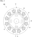
- FIG. 3 is a cross-sectional view of a permanent magnet synchronous motor 200 according to Comparative Example.
- the rotor core 21 is provided with four lightening holes 31. That is, in Comparative Example, the number Nl of the lightening holes 31 is the same as the number Pm of pole pairs of the permanent magnets 22.
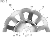
- FIG. 2 is a diagram showing a magnetic flux density distribution of a 1/2 model of the permanent magnet synchronous motor 100 according to Example 1 as an example of this embodiment.
- FIG. 4 is a diagram showing a magnetic flux density distribution of a 1/2 model of the permanent magnet synchronous motor 200 according to Comparative Example.
- the 1/2 model is a model showing one-half of the permanent magnet synchronous motor 100 or 200 divided in the circumferential direction. Since the permanent magnet synchronous motors 100 and 200 have two-fold symmetry with respect to the axis O, the analysis is performed using the 1/2 model. In FIGS. 2 and 4 , the magnetic flux density becomes higher as the color becomes darker and the magnetic flux density becomes lower as the color becomes lighter.
- Example 1 when a first separation angle around the axis O between both ends of the lightening hole 31 in the circumferential direction is ⁇ and a second separation angle around the axis O between the centers of the permanent magnets 22 adjacent to each other in the circumferential direction is ⁇ , the first separation angle ⁇ is the same as the second separation angle ⁇ . Additionally, when the number of the permanent magnets 22 is Nm, the second separation angle ⁇ is 360°/Nm.
- the magnetic flux density of a portion 21a located between the lightening hole 31 and the permanent magnet 22 is higher than the magnetic flux density of the other portion 21b.
- the specific magnetic permeability of the portion 21a located between the lightening hole 31 and the permanent magnet 22 is smaller than the specific magnetic permeability of the other portion 21b.
- the magnetic resistance of the portion 21a located between the lightening hole 31 and the permanent magnet 22 is larger than the magnetic resistance of the other portion 21b.
- the permeance coefficient of the permanent magnet 22 facing the lightening hole 31 is smaller than the permeance coefficient of the other permanent magnets 22.
- the magnetic flux generated by the permanent magnet 22 facing the lightening hole 31 is smaller than the magnetic flux generated by the other permanent magnet 22. That is, even when there is no manufacturing variation in the rotor 20, variations in characteristics among the plurality of permanent magnets 22 are caused by providing the lightening holes 31. As a result, distortion occurs in the magnetic flux density of the air gap 15, and cogging torque or torque pulsation is generated.
- the cogging torque or the torque pulsation generated in this way includes a harmonic component that matches the number of the teeth 13 (for example, when the number of the teeth 13 is 12, a 12th harmonic component) per mechanical angle rotation.
- the number Nl of the lightening holes 31 is the same as the number Pm of pole pairs of the permanent magnets 22.
- a portion (the portion 21a located between the lightening hole 31 and the permanent magnet 22) in which the magnetic flux density is relatively high and a portion (the other portion 21b) in which the magnetic flux density is relatively low appear alternately for each pole in the outer peripheral portion of the rotor core 21.
- the change in magnetic flux density over the entire outer peripheral portion of the rotor core 21 increases. That is, the magnetic flux generated by the permanent magnets 22 increases and decreases periodically for each pole. Further, the change in magnetic flux generated by the permanent magnets 22 increases. As a result, the distortion of the magnetic flux density in the air gap 15 increases, and the cogging torque or the torque pulsation increases.
- the 8-pole/12-slot permanent magnet synchronous motor is configured with circumferentially adjacent two permanent magnets 22 and three teeth 13 (two poles and three slots) as a basic unit. Therefore, the difference in characteristics of two permanent magnets 22 adjacent to each other in the circumferential direction has a large effect on the generation of the cogging torque or the torque pulsation.
- the magnetic flux generated by the permanent magnets 22 increases and decreases periodically for each pole. Thus, since the difference in characteristics between the two permanent magnets 22 adjacent to each other in the circumferential direction increases, the cogging torque or the torque pulsation further increases.
- the number N1 of the lightening holes 31 is different from the number Pm of pole pairs of the permanent magnets 22.
- a portion (the portion 21a between the lightening hole 31 and the permanent magnet 22) in which the magnetic flux density is relatively high and a portion (the other portion 21b) in which the magnetic flux density is relatively low exist in the outer peripheral portion of the rotor core 21, but the change in magnetic flux density over the entire outer peripheral portion of the rotor core 21 decreases compared to Comparative Example.
- FIG. 5 is a graph showing a torque waveform variation component obtained by the permanent magnet synchronous motor 100 according to Example 1 and a torque waveform variation component obtained by the permanent magnet synchronous motor 200 according to Comparative Example.
- the vertical axis of the graph in FIG. 5 indicates the torque waveform variation component [p.u.] normalized based on the torque waveform variation component obtained by the permanent magnet synchronous motor 200 according to Comparative Example.
- the torque waveform variation component of the present disclosure is a harmonic component that occurs in the torque waveform due to variation in characteristics between the plurality of permanent magnets 22.
- the torque waveform variation component in FIG. 5 is obtained by dividing the torque waveform obtained from electromagnetic field analysis into multiple harmonic components by Fourier series expansion and extracting the value of the 12th harmonic component from these multiple harmonic components. The cogging torque and the torque pulsation increase as the torque waveform variation component increases.
- the torque waveform variation component decreases by about 50% compared to the permanent magnet synchronous motor 200 according to Comparative Example. That is, in the permanent magnet synchronous motor 100 according to Example 1, it can be seen that the cogging torque and the torque pulsation can be reduced.
- FIG. 6 is a diagram showing a magnetic flux density distribution of a 1/2 model of the permanent magnet synchronous motor 100 according to Example 2 as an example of this embodiment.
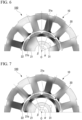
- FIG. 7 is a diagram showing a magnetic flux density distribution of a 1/2 model of the permanent magnet synchronous motor 100 according to Example 3 as an example of this embodiment.
- FIG. 8 is a graph showing a torque waveform variation component obtained by the permanent magnet synchronous motor 100 according to Examples 1 to 3. The vertical axis of the graph in FIG. 8 indicates the torque waveform variation component [p.u.] normalized based on the torque waveform variation component obtained by the permanent magnet synchronous motor 200 according to Comparative Example.
- Example 2 the first separation angle ⁇ is twice the second separation angle ⁇ . As shown in FIG. 7 , in Example 3, the first separation angle ⁇ is three times the second separation angle ⁇ . In Examples 2 and 3, the lightening hole 31 is disposed across three permanent magnets 22.
- the rotor 20 includes the rotor core 21, the shaft 23 which is disposed inside the rotor core 21 and extends in the axial direction, and the plurality of permanent magnets 22 which are provided in the rotor core 21.
- the rotor core 21 is provided with the lightening hole 31.
- the number N1 of the lightening holes 31 is different from the number Pm of pole pairs of the permanent magnets 22.
- the lightening hole 31 is provided to satisfy ⁇ 3 ⁇ . With this configuration, it is possible to more effectively reduce the cogging torque and the torque pulsation. Further, it is possible to enlarge the lightening hole 31 and to more reliably reduce the weight of the rotor 20.
- FIG. 9 is a cross-sectional view showing a rotor 20A according to Embodiment 2.
- the stator 10 is provided on the outer peripheral side of the rotor 20A with the air gap 15 interposed therebetween (see FIG. 1 ). Additionally, components having the same functions and operations as those in Embodiment 1 are indicated by the same reference numerals and descriptions thereof are omitted.
- the lightening hole 31 is disposed such that the circumferential center of the lightening hole 31 and the intermediate position of the permanent magnets 22 adjacent to each other in the circumferential direction coincide with each other in the circumferential direction.
- the lightening hole 31 is formed symmetrically with respect to a line connecting the axis O and the circumferential center of the lightening hole 31 (that is, a line connecting the axis O and the intermediate position of the permanent magnets 22 adjacent to each other in the circumferential direction).
- the rotor core 21 is provided with two lightening holes 31 and the number N1 of the lightening holes 31 is different from the number Pm of pole pairs of the permanent magnets 22 similar to Embodiment 1.
- FIG. 10 is a diagram showing a magnetic flux density distribution of a 1/2 model of a permanent magnet synchronous motor 100A according to Example 4 as an example of this embodiment.
- FIG. 11 is a diagram showing a magnetic flux density distribution of a 1/2 model of the permanent magnet synchronous motor 100A according to Example 5 as an example of this embodiment.
- FIG. 12 is a diagram showing a magnetic flux density distribution of a 1/2 model of the permanent magnet synchronous motor 100A according to Example 6 as an example of this embodiment.
- FIG. 13 is a graph showing a torque waveform variation component obtained by the permanent magnet synchronous motor 100A according to Examples 4 to 6. The vertical axis of the graph in FIG. 13 indicates the torque waveform variation component [p.u.] normalized based on the torque waveform variation component obtained by the permanent magnet synchronous motor 200 according to Comparative Example.
- Example 4 the first separation angle ⁇ is the same as the second separation angle ⁇ . As shown in FIG. 11 , in Example 5, the first separation angle ⁇ is twice the second separation angle ⁇ . In Examples 4 and 5, the lightening hole 31 is disposed across two permanent magnets 22. As shown in FIG. 12 , in Example 6, the first separation angle ⁇ is three times the second separation angle ⁇ . In Example 6, the lightening hole 31 is disposed across four permanent magnets 22.
- the difference in characteristics of two permanent magnets 22 adjacent to each other in the circumferential direction has a large effect on the generation of the cogging torque and the torque pulsation.
- the center of the lightening hole 31 in the circumferential direction and the intermediate position of the permanent magnets 22 adjacent to each other in the circumferential direction coincide with each other in the circumferential direction and the lightening hole 31 is formed symmetrically with respect to a line connecting the axis O and the intermediate position of the permanent magnets 22 adjacent to each other in the circumferential direction.
- the lightening hole 31 is disposed such that the center of the lightening hole 31 in the circumferential direction and the intermediate position of the permanent magnets 22, of the plurality of permanent magnets 22, adjacent to each other in the circumferential direction coincide with each other in the circumferential direction.
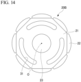
- FIG. 14 is a cross-sectional view showing a rotor 20B according to Embodiment 3.
- the stator 10 is provided on the outer peripheral side of the rotor 20B with the air gap 15 interposed therebetween (see FIG. 1 ). Additionally, components having the same functions and operations as those in Embodiment 1 are indicated by the same reference numerals and descriptions thereof are omitted.
- the rotor core 21 is provided with three lightening holes 31.
- Three lightening holes 31 are arranged at equal intervals in the circumferential direction.
- the number N1 of the lightening holes 31 is 3.
- the number N1 of the lightening holes 31 is different from the number Pm of pole pairs of the permanent magnets 22.
- the number N1 of the lightening holes 31 is smaller than the number Pm of pole pairs of the permanent magnets 22. Further, the number N1 of the lightening holes 31 is also different from the number Nm of the permanent magnets 22.
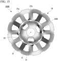
- FIG. 15 is a diagram showing a magnetic flux density distribution of a permanent magnet synchronous motor 100B according to Example 7 as an example of this embodiment.
- FIG. 17 is a graph showing a torque waveform variation component obtained by the permanent magnet synchronous motor 100B according to Example 7. The vertical axis of the graph in FIG. 17 indicates the torque waveform variation component [p.u.] normalized based on the torque waveform variation component obtained by the permanent magnet synchronous motor 200 according to Comparative Example.
- Example 7 As shown in FIG. 15 , in the permanent magnet synchronous motor 100B according to Example 7, the change in magnetic flux density of the outer peripheral portion of the rotor core 21 decreases compared to Comparative Example. Further, as shown in FIG. 17 , in the permanent magnet synchronous motor 100B according to Example 7, it can be confirmed that the torque waveform variation component decreases by about 70% compared to the permanent magnet synchronous motor 200 according to Comparative Example. Thus, in Example 7, it can be seen that the cogging torque and the torque pulsation can be reduced.
- the permanent magnet synchronous motor 100B As the number N1 of the lightening holes 31 is increased, it is possible to further suppress variations in magnetic flux density in the outer peripheral portion of the rotor core 21 and to further decrease the change in magnetic flux generated by the permanent magnets 22. As a result, it is possible to further reduce the distortion of the magnetic flux density in the air gap 15 and to further reduce the cogging torque and the torque pulsation.
- FIG. 16 is a diagram showing a magnetic flux density distribution of a permanent magnet synchronous motor 100C according to Example 8 as an example of this embodiment.
- FIG. 17 is a graph showing a torque waveform variation component obtained by the permanent magnet synchronous motor 100C according to Example 8. Additionally, components having the same functions and operations as those in Embodiment 1 are indicated by the same reference numerals and descriptions thereof are omitted.
- the rotor core 21 of the rotor 20C is provided with five lightening holes 31.
- Five lightening holes 31 are arranged at equal intervals in the circumferential direction.
- the number N1 of the lightening holes 31 is 5.
- the number N1 of the lightening holes 31 is different from the number Pm of pole pairs of the permanent magnets 22.
- the number N1 of the lightening holes 31 is larger than the number Pm of pole pairs of the permanent magnets 22. Further, the number N1 of the lightening holes 31 is also different from the number Nm of the permanent magnets 22.
- Example 8 As shown in FIG. 16 , in the permanent magnet synchronous motor 100C according to Example 8, the change in magnetic flux density in the outer peripheral portion of the rotor core 21 decreases compared to Comparative Example. Further, as shown in FIG. 17 , in the permanent magnet synchronous motor 100C according to Example 8, it can be confirmed that the torque waveform variation component remarkably decreases compared to the permanent magnet synchronous motor 200 according to Comparative Example. Thus, in Example 8, it can be seen that the cogging torque and the torque pulsation can be reduced.
- the number N1 of the lightening holes 31 is larger than the number Pm of pole pairs of the permanent magnets 22. Accordingly, variations in magnetic flux density in the outer peripheral portion of the rotor core 21 are further suppressed and the change in magnetic flux generated by the permanent magnet 22 is further reduced. As a result, it is possible to further reduce the distortion of the magnetic flux density in the air gap 15 and to further reduce the cogging torque and the torque pulsation.
- FIG. 18 is a cross-sectional view showing a rotor 20D according to Embodiment 5.
- the stator 10 is provided on the outer peripheral side of the rotor 20D with the air gap 15 interposed therebetween (see FIG. 1 ). Additionally, components having the same functions and operations as those in Embodiment 1 are indicated by the same reference numerals and descriptions thereof are omitted.
- the rotor core 21 is provided with a plurality of positioning holes 32 in addition to the lightening holes 31.
- the rotor core 21 includes a plurality of core plates which are stacked in the axial direction. In order to ensure uniformity of the rotor core 21 in the circumferential direction, the plurality of core plates are stacked while shifting the angle of each core plate (that is, the plurality of core plates are rotated and stacked). By providing the positioning holes 32, the relative positions of the core plates can be easily adjusted when the plurality of core plates are rotated and stacked.
- the rotor core 21 is provided with two lightening holes 31 and six positioning holes 32.
- the lightening holes 31 and the positioning holes 32 are arranged at equal intervals (intervals of 45°) in the circumferential direction.
- the number of the lightening holes 31, the number of the positioning holes 32, and the arrangement of the lightening holes 31 and the positioning holes 32 are not limited thereto.
- the rotor core 21 may be provided with two positioning holes 32.
- the lightening holes 31 and the positioning holes 32 are arranged at equal intervals (intervals of 90°) in the circumferential direction.
- the shape of the positioning hole 32 is not limited to a circle, and may be a square, a trapezoid, a sector, or the like.
- FIG. 19 is a diagram showing a magnetic flux density distribution of a 1/2 model of a permanent magnet synchronous motor 100D according to Example 9 as an example of this embodiment.
- FIG. 21 is a diagram showing a magnetic flux density distribution of a 1/2 model of the permanent magnet synchronous motor 100D according to Example 10 as an example of this embodiment.
- FIG. 22 is a graph showing a torque waveform variation component obtained by the permanent magnet synchronous motor 100D according to Examples 9 and 10. The vertical axis of the graph in FIG. 22 indicates the torque waveform variation component [p.u.] normalized based on the torque waveform variation component obtained by the permanent magnet synchronous motor 200 according to Comparative Example.
- the permanent magnet synchronous motor 100D according to Example 9 is formed by providing six positioning holes 32 in the rotor core 21 of the permanent magnet synchronous motor 100 according to Example 1.
- the permanent magnet synchronous motor 100D according to Example 10 is formed by providing two positioning holes 32 in the rotor core 21 of the permanent magnet synchronous motor 100 according to Example 1.
- the change in magnetic flux density of the outer peripheral portion of the rotor core 21 decreases compared to Comparative Example.
- FIG. 22 in the permanent magnet synchronous motor 100D according to Examples 9 and 10, it can be confirmed that the torque waveform variation component decreases by about 60% compared to the permanent magnet synchronous motor 200 according to Comparative Example. That is, it can be seen that the formation of the positioning hole 32 does not increase the torque waveform variation component and the cogging torque and the torque pulsation can be reduced in the permanent magnet synchronous motor 100D provided with the positioning hole 32.
- an interior permanent magnetic (IPM) motor in which the plurality of permanent magnets 22 are embedded in the rotor core 21 may be employed.
- the positioning hole 32 shown in FIGS. 19 and 21 may be provided in the rotor core 21 according to other embodiments.
Landscapes
- Engineering & Computer Science (AREA)
- Power Engineering (AREA)
- Permanent Field Magnets Of Synchronous Machinery (AREA)
- Permanent Magnet Type Synchronous Machine (AREA)
Abstract
Description
- The present disclosure relates to a rotor and a permanent magnet synchronous motor.
- Conventionally, a permanent magnet synchronous motor is known as a motor used in an in-vehicle device used in an electric automobile and the like, a compressor used in an air conditioner and the like, and an industrial machine. The permanent magnet synchronous motor includes a stator and a rotor which is rotatably provided in the stator. The rotor includes a rotor core and a plurality of permanent magnets provided in the rotor core. In
Patent Document 1, a lightening hole is provided in the rotor core in order to reduce the weight of the rotor. - [Patent Document 1]
Japanese Unexamined Patent Application, First Publication No. 2015-47051 - Since the lightening hole is provided in the rotor core, there is a possibility that cogging torque or torque pulsation may be generated. In the permanent magnet synchronous motor, it is required to reduce the cogging torque and the torque pulsation.
- The present disclosure has been made to solve the above-described problems and an object thereof is to provide a rotor and a permanent magnet synchronous motor capable of reducing cogging torque and torque pulsation while reducing weight.
- A rotor according to the present disclosure includes a rotor core, a shaft which is disposed inside the rotor core and extends in an axial direction, and a plurality of permanent magnets which are provided in the rotor core, in which the rotor core is provided with a lightening hole, and a number of the lightening hole is different from a number of pole pairs of the plurality of permanent magnets.
- A permanent magnet synchronous motor according to the present disclosure includes the rotor, and a stator which is provided to surround the outer periphery of the rotor.
- According to the present disclosure, it is possible to provide a rotor and a permanent magnet synchronous motor capable of reducing cogging torque or torque pulsation while reducing weight.
-
-
FIG. 1 is a cross-sectional view of a permanent magnet synchronous motor according toEmbodiment 1. -
FIG. 2 is a diagram showing a magnetic flux density distribution of a 1/2 model of a permanent magnet synchronous motor according to Example 1. -
FIG. 3 is a cross-sectional view of a permanent magnet synchronous motor according to Comparative Example. -
FIG. 4 is a diagram showing a magnetic flux density distribution of a 1/2 model of the permanent magnet synchronous motor according to Comparative Example. -
FIG. 5 is a graph showing torque waveform variation components obtained by the permanent magnet synchronous motors according to Example 1 and Comparative Example. -
FIG. 6 is a diagram showing a magnetic flux density distribution of a 1/2 model of a permanent magnet synchronous motor according to Example 2. -
FIG. 7 is a diagram showing a magnetic flux density distribution of a 1/2 model of a permanent magnet synchronous motor according to Example 3. -
FIG. 8 is a graph showing torque waveform variation components obtained by the permanent magnet synchronous motors according to Examples 1 to 3. -
FIG. 9 is a cross-sectional view of a rotor according toEmbodiment 2. -
FIG. 10 is a diagram showing a magnetic flux density distribution of a 1/2 model of a permanent magnet synchronous motor according to Example 4. -
FIG. 11 is a diagram showing a magnetic flux density distribution of a 1/2 model of a permanent magnet synchronous motor according to Example 5. -
FIG. 12 is a diagram showing a magnetic flux density distribution of a 1/2 model of a permanent magnet synchronous motor according to Example 6. -
FIG. 13 is a graph showing torque waveform variation components obtained by the permanent magnet synchronous motors according to Examples 4 to 6. -
FIG. 14 is a cross-sectional view of a rotor according toEmbodiment 3. -
FIG. 15 is a diagram showing a magnetic flux density distribution of a permanent magnet synchronous motor according to Example 7. -
FIG. 16 is a diagram showing a magnetic flux density distribution of a permanent magnet synchronous motor according to Example 8. -
FIG. 17 is a graph showing torque waveform variation components obtained by the permanent magnet synchronous motors according to Examples 7 and 8. -
FIG. 18 is a cross-sectional view of a rotor according toEmbodiment 5. -
FIG. 19 is a diagram showing a magnetic flux density distribution of a 1/2 model of a permanent magnet synchronous motor according to Example 9. -
FIG. 20 is a cross-sectional view of a rotor according to Modified Example ofEmbodiment 5. -
FIG. 21 is a diagram showing a magnetic flux density distribution of a 1/2 model of a permanent magnet synchronous motor according to Example 10. -
FIG. 22 is a graph showing torque waveform variation components obtained by the permanent magnet synchronous motors according to Examples 9 and 10. -
FIG. 1 is a cross-sectional view of a permanent magnetsynchronous motor 100 ofEmbodiment 1 cut in a direction perpendicular to the axial direction. The permanent magnetsynchronous motor 100 includes astator 10 and arotor 20 which is provided inside thestator 10. Therotor 20 is rotatable around an axis O with respect to thestator 10. - In the present specification, a direction along the axis O of the
rotor 20 is referred to as an "axial direction". Further, a section perpendicular to the axial direction is referred to as a "cross-section". In the cross-section, a direction intersecting the axis O is referred to as a "radial direction" and a direction around the axis O is referred to as a "circumferential direction". - The
stator 10 is provided to surround the outer periphery of therotor 20. Anair gap 15 is formed between the inner periphery of thestator 10 and the outer periphery of therotor 20. Theair gap 15 is formed over the entire circumference in the circumferential direction. - The
stator 10 includes astator core 11 and a plurality ofwindings 14. Thestator core 11 includes an annular core back 12 and a plurality ofteeth 13. The core back 12 includes a plurality ofcore blocks 12a which are formed in an arc shape along the circumferential direction and is formed in an annular shape by arranging thecore blocks 12a in the circumferential direction. Eachtooth 13 protrudes inward in the radial direction from the circumferential center of eachcore block 12a. Eachwinding 14 is wound around each of the plurality ofteeth 13. - In the configuration shown in
FIG. 1 , the core back 12 is formed by the plurality ofcore blocks 12a. However, the core back 12 may be integrally formed in an annular shape. Further, in the configuration shown inFIG. 1 , the core back 12 and the plurality ofteeth 13 are integrally formed with each other. However, the core back 12 and the plurality ofteeth 13 may both be individually formed. - The
rotor 20 includes arotor core 21, a plurality ofpermanent magnets 22, and ashaft 23. Therotor core 21 has a cylindrical shape extending in the axial direction. Therotor core 21 is formed of a magnetic material. Therotor core 21 is formed, for example, by stacking a plurality of core plates such as electromagnetic steel plates in the axial direction. Theshaft 23 is disposed inside therotor core 21 and extends in the axial direction. Theshaft 23 is fixed to therotor core 21. - The plurality of
permanent magnets 22 are provided on the outer peripheral surface of therotor core 21 at intervals in the circumferential direction. The plurality ofpermanent magnets 22 are arranged at equal intervals in the circumferential direction. Eachpermanent magnet 22 is magnetized such that an S pole or an N pole appears on an outer peripheral surface (a surface facing the stator 10) thereof. Thepermanent magnets 22 which are adjacent to each other in the circumferential direction are magnetized such that the poles appearing on their outer peripheral surfaces are different from each other. That is, when the outer peripheral surface of one of the circumferentially adjacentpermanent magnets 22 is an N pole, the outer peripheral surface of the other thereof is an S pole. The permanentmagnet synchronous motor 100 of this embodiment is a surface permanent magnetic (SPM) motor in which the plurality ofpermanent magnets 22 are arranged on the outer peripheral surface of therotor core 21. - In the configuration shown in
FIG. 1 , the number of theteeth 13 is 12. The number of thewindings 14 is 12. The number Nm of the permanent magnets 22 (that is, the number of magnetic poles) is 8. Further, the number Pm of pole pairs of thepermanent magnets 22 having pairs of N and S poles is 4. That is, the permanentmagnet synchronous motor 100 in this embodiment is a so-called 8-pole/12-slot motor. - The numbers of the
teeth 13, thewindings 14, and thepermanent magnets 22 are not limited thereto. The number of theteeth 13 may be different from the number of thewindings 14. - The
rotor core 21 is provided with a plurality of lightening holes 31. Since the lightening holes 31 are provided, the weight of therotor 20 can be reduced and the inertia moment of therotor 20 can be reduced. - The lightening
hole 31 is formed to penetrate therotor core 21 in the axial direction. The lighteninghole 31 is formed in an arc shape along the circumferential direction. The plurality of lighteningholes 31 are arranged at equal intervals in the circumferential direction. The plurality of lighteningholes 31 have the same shape. The lighteninghole 31 is disposed on the inside of thepermanent magnet 22 in the radial direction. The lighteninghole 31 is disposed such that the circumferential center of the lighteninghole 31 and the circumferential center of thepermanent magnet 22 coincide with each other in the circumferential direction. The lighteninghole 31 is formed symmetrically with respect to a line connecting the axis O of theshaft 23 and the circumferential center of the lighteninghole 31. - In this embodiment, the number Nl of the lightening holes 31 is 2. That is, the number N1 of the lightening holes 31 is different from the number Pm of pole pairs of the
permanent magnets 22. The number N1 of the lightening holes 31 is smaller than the number Pm of pole pairs of thepermanent magnets 22. Further, the number Nl of the lightening holes 31 is also different from the number Nm of thepermanent magnets 22. - The operation of the permanent
magnet synchronous motor 100 will be described. - When power is supplied to the
windings 14, a rotating magnetic field is generated in thestator 10. Thepermanent magnets 22 rotate while following this rotating magnetic field. Accordingly, therotor 20 rotates around the axis O with respect to thestator 10. - As shown in the following formula (1), the torque T of the permanent
magnet synchronous motor 100 is obtained by differentiating the magnetic energy Wm within theair gap 15 between thestator 10 and therotor 20 by the rotation angle θ.
- Further, as shown in the following formula (2), the magnetic energy Wm is obtained by the magnetic flux density Bg and the magnetic permeability µ0 in the
air gap 15.
- The magnetic flux density Bg in the
air gap 15 is determined by the magnetomotive force generated by thewindings 14, the shape of thestator 10, the magnetic flux generated by thepermanent magnets 22, and the like. Further, when there are manufacturing variations (for example, variations in dimensions, arrangement, magnetization, and the like between the plurality of permanent magnets 22) in therotor 20, distortion may occur in the magnetic flux density Bg in theair gap 15 and hence cogging torque or torque pulsation may occur. - The operation of the permanent
magnet synchronous motor 100 according to this embodiment will be described by the comparison with Comparative Example shown inFIG. 3. FIG. 3 is a cross-sectional view of a permanentmagnet synchronous motor 200 according to Comparative Example. In the permanentmagnet synchronous motor 200, therotor core 21 is provided with four lightening holes 31. That is, in Comparative Example, the number Nl of the lightening holes 31 is the same as the number Pm of pole pairs of thepermanent magnets 22. -
FIG. 2 is a diagram showing a magnetic flux density distribution of a 1/2 model of the permanentmagnet synchronous motor 100 according to Example 1 as an example of this embodiment.FIG. 4 is a diagram showing a magnetic flux density distribution of a 1/2 model of the permanentmagnet synchronous motor 200 according to Comparative Example. The 1/2 model is a model showing one-half of the permanentmagnet synchronous motor synchronous motors FIGS. 2 and4 , the magnetic flux density becomes higher as the color becomes darker and the magnetic flux density becomes lower as the color becomes lighter. - As shown in
FIG. 2 , in Example 1, when a first separation angle around the axis O between both ends of the lighteninghole 31 in the circumferential direction is α and a second separation angle around the axis O between the centers of thepermanent magnets 22 adjacent to each other in the circumferential direction is β, the first separation angle α is the same as the second separation angle β. Additionally, when the number of thepermanent magnets 22 is Nm, the second separation angle β is 360°/Nm. - As shown in
FIGS. 2 and4 , in the outer peripheral portion of therotor core 21, the magnetic flux density of aportion 21a located between the lighteninghole 31 and thepermanent magnet 22 is higher than the magnetic flux density of theother portion 21b. At this time, the specific magnetic permeability of theportion 21a located between the lighteninghole 31 and thepermanent magnet 22 is smaller than the specific magnetic permeability of theother portion 21b. The magnetic resistance of theportion 21a located between the lighteninghole 31 and thepermanent magnet 22 is larger than the magnetic resistance of theother portion 21b. Thus, the permeance coefficient of thepermanent magnet 22 facing the lighteninghole 31 is smaller than the permeance coefficient of the otherpermanent magnets 22. The magnetic flux generated by thepermanent magnet 22 facing the lighteninghole 31 is smaller than the magnetic flux generated by the otherpermanent magnet 22. That is, even when there is no manufacturing variation in therotor 20, variations in characteristics among the plurality ofpermanent magnets 22 are caused by providing the lightening holes 31. As a result, distortion occurs in the magnetic flux density of theair gap 15, and cogging torque or torque pulsation is generated. The cogging torque or the torque pulsation generated in this way includes a harmonic component that matches the number of the teeth 13 (for example, when the number of theteeth 13 is 12, a 12th harmonic component) per mechanical angle rotation. - In the permanent
magnet synchronous motor 200 according to Comparative Example, the number Nl of the lightening holes 31 is the same as the number Pm of pole pairs of thepermanent magnets 22. Thus, as shown inFIG. 4 , a portion (theportion 21a located between the lighteninghole 31 and the permanent magnet 22) in which the magnetic flux density is relatively high and a portion (theother portion 21b) in which the magnetic flux density is relatively low appear alternately for each pole in the outer peripheral portion of therotor core 21. Further, the change in magnetic flux density over the entire outer peripheral portion of therotor core 21 increases. That is, the magnetic flux generated by thepermanent magnets 22 increases and decreases periodically for each pole. Further, the change in magnetic flux generated by thepermanent magnets 22 increases. As a result, the distortion of the magnetic flux density in theair gap 15 increases, and the cogging torque or the torque pulsation increases. - Additionally, the 8-pole/12-slot permanent magnet synchronous motor is configured with circumferentially adjacent two
permanent magnets 22 and three teeth 13 (two poles and three slots) as a basic unit. Therefore, the difference in characteristics of twopermanent magnets 22 adjacent to each other in the circumferential direction has a large effect on the generation of the cogging torque or the torque pulsation. In the permanentmagnet synchronous motor 200 according to Comparative Example, the magnetic flux generated by thepermanent magnets 22 increases and decreases periodically for each pole. Thus, since the difference in characteristics between the twopermanent magnets 22 adjacent to each other in the circumferential direction increases, the cogging torque or the torque pulsation further increases. - On the other hand, in the permanent
magnet synchronous motor 100 according to Example 1, the number N1 of the lightening holes 31 is different from the number Pm of pole pairs of thepermanent magnets 22. Thus, as shown inFIG. 2 , a portion (theportion 21a between the lighteninghole 31 and the permanent magnet 22) in which the magnetic flux density is relatively high and a portion (theother portion 21b) in which the magnetic flux density is relatively low exist in the outer peripheral portion of therotor core 21, but the change in magnetic flux density over the entire outer peripheral portion of therotor core 21 decreases compared to Comparative Example. Further, it is possible to prevent a portion in which the magnetic flux density is relatively high and a portion in which the magnetic flux density is relatively low from appearing alternately for each pole in the outer peripheral portion of therotor core 21. Thus, the change in magnetic flux generated by thepermanent magnets 22 decreases compared to Comparative Example. Further, the magnetic flux generated by thepermanent magnets 22 does not periodically increase and decrease for each pole. As a result, it is possible to reduce distortion of the magnetic flux density in theair gap 15 and to reduce the cogging torque, the torque pulsation and the like. -
FIG. 5 is a graph showing a torque waveform variation component obtained by the permanentmagnet synchronous motor 100 according to Example 1 and a torque waveform variation component obtained by the permanentmagnet synchronous motor 200 according to Comparative Example. The vertical axis of the graph inFIG. 5 indicates the torque waveform variation component [p.u.] normalized based on the torque waveform variation component obtained by the permanentmagnet synchronous motor 200 according to Comparative Example. The torque waveform variation component of the present disclosure is a harmonic component that occurs in the torque waveform due to variation in characteristics between the plurality ofpermanent magnets 22. The torque waveform variation component inFIG. 5 is obtained by dividing the torque waveform obtained from electromagnetic field analysis into multiple harmonic components by Fourier series expansion and extracting the value of the 12th harmonic component from these multiple harmonic components. The cogging torque and the torque pulsation increase as the torque waveform variation component increases. - As shown in
FIG. 5 , in the permanentmagnet synchronous motor 100 according to Example 1, it can be confirmed that the torque waveform variation component decreases by about 50% compared to the permanentmagnet synchronous motor 200 according to Comparative Example. That is, in the permanentmagnet synchronous motor 100 according to Example 1, it can be seen that the cogging torque and the torque pulsation can be reduced. -
FIG. 6 is a diagram showing a magnetic flux density distribution of a 1/2 model of the permanentmagnet synchronous motor 100 according to Example 2 as an example of this embodiment.FIG. 7 is a diagram showing a magnetic flux density distribution of a 1/2 model of the permanentmagnet synchronous motor 100 according to Example 3 as an example of this embodiment.FIG. 8 is a graph showing a torque waveform variation component obtained by the permanentmagnet synchronous motor 100 according to Examples 1 to 3. The vertical axis of the graph inFIG. 8 indicates the torque waveform variation component [p.u.] normalized based on the torque waveform variation component obtained by the permanentmagnet synchronous motor 200 according to Comparative Example. - As shown in
FIG. 6 , in Example 2, the first separation angle α is twice the second separation angle β. As shown inFIG. 7 , in Example 3, the first separation angle α is three times the second separation angle β. In Examples 2 and 3, the lighteninghole 31 is disposed across threepermanent magnets 22. - As shown in
FIGS. 6 and 7 , in the permanentmagnet synchronous motor 100 according to Examples 2 and 3, the change in magnetic flux density over the entire outer peripheral portion of therotor core 21 decreases compared to Comparative Example. Further, as shown inFIG. 8 , in the permanentmagnet synchronous motor 100 according to Example 2, it can be confirmed that the torque waveform variation component decreases by about 75% compared to the permanentmagnet synchronous motor 200 according to Comparative Example. In the permanentmagnet synchronous motor 100 according to Example 3, it can be confirmed that the torque waveform variation component decreases by about 55% compared to the permanentmagnet synchronous motor 200 according to Comparative Example. Thus, in the permanentmagnet synchronous motor 100 according to Examples 2 and 3, it can be seen that the cogging torque and the torque pulsation can be reduced. As described above, when the lighteninghole 31 is formed such that the first separation angle α satisfies β≤α≤3β, it can be seen that the cogging torque and the torque pulsation can be more effectively reduced. - As described above, the
rotor 20 according to this embodiment includes therotor core 21, theshaft 23 which is disposed inside therotor core 21 and extends in the axial direction, and the plurality ofpermanent magnets 22 which are provided in therotor core 21. Therotor core 21 is provided with the lighteninghole 31. The number N1 of the lightening holes 31 is different from the number Pm of pole pairs of thepermanent magnets 22. With this configuration, it is possible to reduce the cogging torque and the torque pulsation while decreasing the weight of therotor 20. - Further, when the first separation angle around the axis O between both ends of the lightening
hole 31 in the circumferential direction is α and the second separation angle around the axis O between the centers of thepermanent magnets 22 adjacent each other in the circumferential direction is β, the lighteninghole 31 is provided to satisfy β≤α≤3β. With this configuration, it is possible to more effectively reduce the cogging torque and the torque pulsation. Further, it is possible to enlarge the lighteninghole 31 and to more reliably reduce the weight of therotor 20. -
FIG. 9 is a cross-sectional view showing arotor 20A according toEmbodiment 2. Although not shown in the drawings, thestator 10 is provided on the outer peripheral side of therotor 20A with theair gap 15 interposed therebetween (seeFIG. 1 ). Additionally, components having the same functions and operations as those inEmbodiment 1 are indicated by the same reference numerals and descriptions thereof are omitted. - As shown in
FIG. 9 , inEmbodiment 2, the lighteninghole 31 is disposed such that the circumferential center of the lighteninghole 31 and the intermediate position of thepermanent magnets 22 adjacent to each other in the circumferential direction coincide with each other in the circumferential direction. The lighteninghole 31 is formed symmetrically with respect to a line connecting the axis O and the circumferential center of the lightening hole 31 (that is, a line connecting the axis O and the intermediate position of thepermanent magnets 22 adjacent to each other in the circumferential direction). Further, in this embodiment, therotor core 21 is provided with two lighteningholes 31 and the number N1 of the lightening holes 31 is different from the number Pm of pole pairs of thepermanent magnets 22 similar toEmbodiment 1. -
FIG. 10 is a diagram showing a magnetic flux density distribution of a 1/2 model of a permanentmagnet synchronous motor 100A according to Example 4 as an example of this embodiment.FIG. 11 is a diagram showing a magnetic flux density distribution of a 1/2 model of the permanentmagnet synchronous motor 100A according to Example 5 as an example of this embodiment.FIG. 12 is a diagram showing a magnetic flux density distribution of a 1/2 model of the permanentmagnet synchronous motor 100A according to Example 6 as an example of this embodiment.FIG. 13 is a graph showing a torque waveform variation component obtained by the permanentmagnet synchronous motor 100A according to Examples 4 to 6. The vertical axis of the graph inFIG. 13 indicates the torque waveform variation component [p.u.] normalized based on the torque waveform variation component obtained by the permanentmagnet synchronous motor 200 according to Comparative Example. - As shown in
FIG. 10 , in Example 4, the first separation angle α is the same as the second separation angle β. As shown inFIG. 11 , in Example 5, the first separation angle α is twice the second separation angle β. In Examples 4 and 5, the lighteninghole 31 is disposed across twopermanent magnets 22. As shown inFIG. 12 , in Example 6, the first separation angle α is three times the second separation angle β. In Example 6, the lighteninghole 31 is disposed across fourpermanent magnets 22. - As shown in
FIGS. 10 to 12 , in the permanentmagnet synchronous motor 100A according to Examples 4 to 6, the change in magnetic flux density of the outer peripheral portion of therotor core 21 decreases compared to Comparative Example. Further, as shown inFIG. 13 , in the permanentmagnet synchronous motor 100A according to Examples 4 to 6, it can be confirmed that the torque waveform variation component decreases by about 90% compared to the permanentmagnet synchronous motor 200 according to Comparative Example. Thus, in Examples 4 to 6, it can be seen that the cogging torque and the torque pulsation can be reduced. - Further, when comparing
FIGS. 5 and13 , it can be confirmed that the torque waveform variation component further decreases in the permanentmagnet synchronous motor 100A according to Examples 4 to 6. - As described above, in the 8-pole/12-slot permanent magnet synchronous motor, the difference in characteristics of two
permanent magnets 22 adjacent to each other in the circumferential direction has a large effect on the generation of the cogging torque and the torque pulsation. In this embodiment, the center of the lighteninghole 31 in the circumferential direction and the intermediate position of thepermanent magnets 22 adjacent to each other in the circumferential direction coincide with each other in the circumferential direction and the lighteninghole 31 is formed symmetrically with respect to a line connecting the axis O and the intermediate position of thepermanent magnets 22 adjacent to each other in the circumferential direction. Thus, since the change in magnetic flux density in the outer peripheral portion of therotor core 21 is symmetrical with respect to the above line for thepermanent magnets 22 which are adjacent to each other in the circumferential direction with the circumferential center of the lighteninghole 31 interposed therebetween, the difference in characteristics between these twopermanent magnets 22 decreases. As a result, it is possible to more effectively reduce the cogging torque and the torque pulsation. - As described above, in the
rotor 20A according to this embodiment, the lighteninghole 31 is disposed such that the center of the lighteninghole 31 in the circumferential direction and the intermediate position of thepermanent magnets 22, of the plurality ofpermanent magnets 22, adjacent to each other in the circumferential direction coincide with each other in the circumferential direction. With this configuration, it is possible to more effectively reduce the cogging torque and the torque pulsation. -
FIG. 14 is a cross-sectional view showing arotor 20B according toEmbodiment 3. Although not shown in the drawings, thestator 10 is provided on the outer peripheral side of therotor 20B with theair gap 15 interposed therebetween (seeFIG. 1 ). Additionally, components having the same functions and operations as those inEmbodiment 1 are indicated by the same reference numerals and descriptions thereof are omitted. - As shown in
FIG. 14 , inEmbodiment 3, therotor core 21 is provided with three lightening holes 31. Three lighteningholes 31 are arranged at equal intervals in the circumferential direction. - In this embodiment, the number N1 of the lightening holes 31 is 3. The number N1 of the lightening holes 31 is different from the number Pm of pole pairs of the
permanent magnets 22. The number N1 of the lightening holes 31 is smaller than the number Pm of pole pairs of thepermanent magnets 22. Further, the number N1 of the lightening holes 31 is also different from the number Nm of thepermanent magnets 22. -
FIG. 15 is a diagram showing a magnetic flux density distribution of a permanentmagnet synchronous motor 100B according to Example 7 as an example of this embodiment.FIG. 17 is a graph showing a torque waveform variation component obtained by the permanentmagnet synchronous motor 100B according to Example 7. The vertical axis of the graph inFIG. 17 indicates the torque waveform variation component [p.u.] normalized based on the torque waveform variation component obtained by the permanentmagnet synchronous motor 200 according to Comparative Example. - As shown in
FIG. 15 , in the permanentmagnet synchronous motor 100B according to Example 7, the change in magnetic flux density of the outer peripheral portion of therotor core 21 decreases compared to Comparative Example. Further, as shown inFIG. 17 , in the permanentmagnet synchronous motor 100B according to Example 7, it can be confirmed that the torque waveform variation component decreases by about 70% compared to the permanentmagnet synchronous motor 200 according to Comparative Example. Thus, in Example 7, it can be seen that the cogging torque and the torque pulsation can be reduced. - Further, when comparing
FIGS. 5 and17 , it can be confirmed that the torque waveform variation component further decreases in the permanentmagnet synchronous motor 100B according to Example 7. - In the permanent
magnet synchronous motor 100B, as the number N1 of the lightening holes 31 is increased, it is possible to further suppress variations in magnetic flux density in the outer peripheral portion of therotor core 21 and to further decrease the change in magnetic flux generated by thepermanent magnets 22. As a result, it is possible to further reduce the distortion of the magnetic flux density in theair gap 15 and to further reduce the cogging torque and the torque pulsation. -
FIG. 16 is a diagram showing a magnetic flux density distribution of a permanentmagnet synchronous motor 100C according to Example 8 as an example of this embodiment.FIG. 17 is a graph showing a torque waveform variation component obtained by the permanentmagnet synchronous motor 100C according to Example 8. Additionally, components having the same functions and operations as those inEmbodiment 1 are indicated by the same reference numerals and descriptions thereof are omitted. - As shown in
FIG. 16 , inEmbodiment 4, therotor core 21 of therotor 20C is provided with five lightening holes 31. Five lighteningholes 31 are arranged at equal intervals in the circumferential direction. - In this embodiment, the number N1 of the lightening holes 31 is 5. The number N1 of the lightening holes 31 is different from the number Pm of pole pairs of the
permanent magnets 22. The number N1 of the lightening holes 31 is larger than the number Pm of pole pairs of thepermanent magnets 22. Further, the number N1 of the lightening holes 31 is also different from the number Nm of thepermanent magnets 22. - As shown in
FIG. 16 , in the permanentmagnet synchronous motor 100C according to Example 8, the change in magnetic flux density in the outer peripheral portion of therotor core 21 decreases compared to Comparative Example. Further, as shown inFIG. 17 , in the permanentmagnet synchronous motor 100C according to Example 8, it can be confirmed that the torque waveform variation component remarkably decreases compared to the permanentmagnet synchronous motor 200 according to Comparative Example. Thus, in Example 8, it can be seen that the cogging torque and the torque pulsation can be reduced. - Further, when comparing
FIGS. 5 and17 , it can be confirmed that the torque waveform variation component is further reduced in the permanentmagnet synchronous motor 100C according to Example 8. - In the permanent
magnet synchronous motor 100C, the number N1 of the lightening holes 31 is larger than the number Pm of pole pairs of thepermanent magnets 22. Accordingly, variations in magnetic flux density in the outer peripheral portion of therotor core 21 are further suppressed and the change in magnetic flux generated by thepermanent magnet 22 is further reduced. As a result, it is possible to further reduce the distortion of the magnetic flux density in theair gap 15 and to further reduce the cogging torque and the torque pulsation. -
FIG. 18 is a cross-sectional view showing arotor 20D according toEmbodiment 5. Although not shown in the drawings, thestator 10 is provided on the outer peripheral side of therotor 20D with theair gap 15 interposed therebetween (seeFIG. 1 ). Additionally, components having the same functions and operations as those inEmbodiment 1 are indicated by the same reference numerals and descriptions thereof are omitted. - As shown in
FIG. 18 , inEmbodiment 5, therotor core 21 is provided with a plurality of positioning holes 32 in addition to the lightening holes 31. Therotor core 21 includes a plurality of core plates which are stacked in the axial direction. In order to ensure uniformity of therotor core 21 in the circumferential direction, the plurality of core plates are stacked while shifting the angle of each core plate (that is, the plurality of core plates are rotated and stacked). By providing the positioning holes 32, the relative positions of the core plates can be easily adjusted when the plurality of core plates are rotated and stacked. - In the configuration shown in
FIG. 18 , therotor core 21 is provided with two lighteningholes 31 and six positioning holes 32. The lightening holes 31 and the positioning holes 32 are arranged at equal intervals (intervals of 45°) in the circumferential direction. However, the number of the lightening holes 31, the number of the positioning holes 32, and the arrangement of the lightening holes 31 and the positioning holes 32 are not limited thereto. For example, as shown in Modified Example ofFIG. 20 , therotor core 21 may be provided with two positioning holes 32. In this case, the lightening holes 31 and the positioning holes 32 are arranged at equal intervals (intervals of 90°) in the circumferential direction. Further, the shape of thepositioning hole 32 is not limited to a circle, and may be a square, a trapezoid, a sector, or the like. -
FIG. 19 is a diagram showing a magnetic flux density distribution of a 1/2 model of a permanentmagnet synchronous motor 100D according to Example 9 as an example of this embodiment.FIG. 21 is a diagram showing a magnetic flux density distribution of a 1/2 model of the permanentmagnet synchronous motor 100D according to Example 10 as an example of this embodiment.FIG. 22 is a graph showing a torque waveform variation component obtained by the permanentmagnet synchronous motor 100D according to Examples 9 and 10. The vertical axis of the graph inFIG. 22 indicates the torque waveform variation component [p.u.] normalized based on the torque waveform variation component obtained by the permanentmagnet synchronous motor 200 according to Comparative Example. - The permanent
magnet synchronous motor 100D according to Example 9 is formed by providing sixpositioning holes 32 in therotor core 21 of the permanentmagnet synchronous motor 100 according to Example 1. The permanentmagnet synchronous motor 100D according to Example 10 is formed by providing twopositioning holes 32 in therotor core 21 of the permanentmagnet synchronous motor 100 according to Example 1. - As shown in
FIGS. 19 and21 , in the permanentmagnet synchronous motor 100D according to Examples 9 and 10, the change in magnetic flux density of the outer peripheral portion of therotor core 21 decreases compared to Comparative Example. Further, as shown inFIG. 22 , in the permanentmagnet synchronous motor 100D according to Examples 9 and 10, it can be confirmed that the torque waveform variation component decreases by about 60% compared to the permanentmagnet synchronous motor 200 according to Comparative Example. That is, it can be seen that the formation of thepositioning hole 32 does not increase the torque waveform variation component and the cogging torque and the torque pulsation can be reduced in the permanentmagnet synchronous motor 100D provided with thepositioning hole 32. - Additionally, it is possible to combine each embodiment or to modify or omit each embodiment as appropriate.
- For example, as the permanent
magnet synchronous motor 100, an interior permanent magnetic (IPM) motor in which the plurality ofpermanent magnets 22 are embedded in therotor core 21 may be employed. - The
positioning hole 32 shown inFIGS. 19 and21 may be provided in therotor core 21 according to other embodiments. -
- 10 Stator
- 20, 20A, 20B, 20C, 20D Rotor
- 21 Rotor core
- 22 Permanent magnet
- 23 Shaft
- 31 Lightening hole
- 32 Positioning hole
- 100, 100A, 100B, 100C, 100D Permanent magnet synchronous motor
- O Axis
Claims (7)
- A rotor comprising:a rotor core;a shaft which is disposed inside the rotor core and extends in an axial direction; anda plurality of permanent magnets which are provided in the rotor core,wherein the rotor core is provided with a lightening hole, anda number of the lightening hole is different from a number of pole pairs of the plurality of permanent magnets.
- The rotor according to claim 1,
wherein the lightening hole extends in a circumferential direction and is disposed such that a center of the lightening hole in the circumferential direction and a center of the permanent magnet in the circumferential direction coincide with each other in the circumferential direction. - The rotor according to claim 1,
wherein the lightening hole extends in a circumferential direction and is disposed such that a center of the lightening hole in the circumferential direction and an intermediate position of permanent magnets, of the plurality of permanent magnets, adjacent to each other in the circumferential direction coincide with each other in the circumferential direction. - The rotor according to claim 2 or 3,wherein the plurality of permanent magnets are arranged at equal intervals in the circumferential direction, andwhen a separation angle around an axis of the shaft between both ends of the lightening hole in the circumferential direction is α and a separation angle around the axis of the shaft between the centers of permanent magnets, of the plurality of permanent magnets, adjacent to each other in the circumferential direction is β in a cross-section orthogonal to the axial direction, the lightening hole is provided to satisfy β≤α≤3β.
- The rotor according to any one of claims 1 to 4,
wherein the lightening hole is formed symmetrically with respect to a line connecting an axis of the shaft and a center of the lightening hole in a circumferential direction. - The rotor according to any one of claims 1 to 5,wherein the rotor core includes a plurality of core plate stacked in the axial direction, andthe rotor core is provided with a positioning hole which adjusts positions of the plurality of core plates.
- A permanent magnet synchronous motor comprising:the rotor according to any one of claims 1 to 6; anda stator which is provided to surround an outer periphery of the rotor.
Applications Claiming Priority (1)
| Application Number | Priority Date | Filing Date | Title |
|---|---|---|---|
| PCT/JP2021/039955 WO2023073901A1 (en) | 2021-10-29 | 2021-10-29 | Rotor and permanent magnet sychronous motor |
Publications (2)
| Publication Number | Publication Date |
|---|---|
| EP4425756A1 true EP4425756A1 (en) | 2024-09-04 |
| EP4425756A4 EP4425756A4 (en) | 2024-12-18 |
Family
ID=86157592
Family Applications (1)
| Application Number | Title | Priority Date | Filing Date |
|---|---|---|---|
| EP21962446.7A Pending EP4425756A4 (en) | 2021-10-29 | 2021-10-29 | ROTOR AND PERMANENT MAGNET SYNCHRONOUS MOTOR |
Country Status (5)
| Country | Link |
|---|---|
| US (1) | US20240356394A1 (en) |
| EP (1) | EP4425756A4 (en) |
| JP (1) | JP7708874B2 (en) |
| CN (1) | CN118104106A (en) |
| WO (1) | WO2023073901A1 (en) |
Families Citing this family (1)
| Publication number | Priority date | Publication date | Assignee | Title |
|---|---|---|---|---|
| JP2026061528A (en) * | 2024-09-30 | 2026-04-09 | ダイキン工業株式会社 | Motors, compressors, refrigeration equipment, blowers |
Family Cites Families (10)
| Publication number | Priority date | Publication date | Assignee | Title |
|---|---|---|---|---|
| JP2013126312A (en) * | 2011-12-15 | 2013-06-24 | Panasonic Corp | Electric motor rotor |
| CN102593985B (en) * | 2012-02-29 | 2016-12-14 | 重庆长安汽车股份有限公司 | A kind of surface-mounted rotor and a kind of motor |
| JP5958439B2 (en) | 2013-08-29 | 2016-08-02 | 株式会社デンソー | Rotor and rotating electric machine using the same |
| JP6189699B2 (en) * | 2013-10-03 | 2017-08-30 | 日立オートモティブシステムズ株式会社 | Rotor core, rotor, and rotating electric machine |
| JP6227203B2 (en) * | 2015-07-31 | 2017-11-08 | 三菱電機株式会社 | Rotating electrical machine rotor |
| JP6507273B2 (en) * | 2015-12-18 | 2019-04-24 | ハノン システムズ | Rotor for permanent magnet embedded motor and motor using the same |
| JP2018160956A (en) * | 2017-03-22 | 2018-10-11 | 日立オートモティブシステムズ株式会社 | Brushless motor |
| CN207835199U (en) * | 2017-03-31 | 2018-09-07 | 日本电产株式会社 | Motors, electric power steering and electrical products |
| JP7149783B2 (en) * | 2018-09-14 | 2022-10-07 | 株式会社ミツバ | ELECTRIC MOTOR AND ELECTRIC MOTOR MANUFACTURING METHOD |
| JP2020048286A (en) * | 2018-09-18 | 2020-03-26 | トヨタ自動車株式会社 | Vehicle charging control system |
-
2021
- 2021-10-29 EP EP21962446.7A patent/EP4425756A4/en active Pending
- 2021-10-29 US US18/687,603 patent/US20240356394A1/en active Pending
- 2021-10-29 WO PCT/JP2021/039955 patent/WO2023073901A1/en not_active Ceased
- 2021-10-29 JP JP2023556012A patent/JP7708874B2/en active Active
- 2021-10-29 CN CN202180102853.4A patent/CN118104106A/en active Pending
Also Published As
| Publication number | Publication date |
|---|---|
| WO2023073901A1 (en) | 2023-05-04 |
| EP4425756A4 (en) | 2024-12-18 |
| CN118104106A (en) | 2024-05-28 |
| JP7708874B2 (en) | 2025-07-15 |
| JPWO2023073901A1 (en) | 2023-05-04 |
| US20240356394A1 (en) | 2024-10-24 |
Similar Documents
| Publication | Publication Date | Title |
|---|---|---|
| EP1990895B1 (en) | Stress distributing permanent magnet rotor geometry for electric machines | |
| EP1914863B1 (en) | Permanent-magnet reluctance electrical rotary machine | |
| EP2800243B1 (en) | Rotor or permanent magnet embedded motor, and compressor, blower, and refrigerating/aitr conditioning device using the rotor | |
| JP4591085B2 (en) | Permanent magnet type motor | |
| CN103891102B (en) | Rotor, compressor and the refrigerating air conditioning device of permanent magnet embedded-type electric motivation | |
| EP2712058B1 (en) | Permanent-magnet type rotating electrical machine | |
| JP2011223836A (en) | Permanent magnet type revolving armature | |
| CN108574355A (en) | Rotor of a rotating electrical machine | |
| WO2018235145A1 (en) | Rotating electric machine rotor | |
| US20220368183A1 (en) | Rotor for a synchronous machine | |
| EP4366136A1 (en) | Rotor and motor | |
| US9692266B2 (en) | Spoke-type PM machine with bridge | |
| EP4425756A1 (en) | Rotor and permanent magnet sychronous motor | |
| JP4080273B2 (en) | Permanent magnet embedded motor | |
| CN113273057A (en) | Interior permanent magnet machine with flux distribution gap | |
| US20240022125A1 (en) | Permanent magnet synchronous motor | |
| US20210288532A1 (en) | Electric machines having a radially embedded permanent magnet rotor and methods thereof | |
| JP2023102517A (en) | Rotor and rotary electric machine | |
| EP4329152A1 (en) | Rotor | |
| US12519355B2 (en) | Rotor | |
| WO2020146309A1 (en) | Interior permanent magnet electric machine with tapered bridge structure | |
| JP2025067124A (en) | Rotary electric machine rotor | |
| JP2022055714A (en) | Rotary electric machine | |
| JP2019176738A (en) | Rotary electric machine and method of manufacturing rotor core | |
| HK1087253B (en) | Permanent magnet type rotary motor |
Legal Events
| Date | Code | Title | Description |
|---|---|---|---|
| STAA | Information on the status of an ep patent application or granted ep patent |
Free format text: STATUS: THE INTERNATIONAL PUBLICATION HAS BEEN MADE |
|
| PUAI | Public reference made under article 153(3) epc to a published international application that has entered the european phase |
Free format text: ORIGINAL CODE: 0009012 |
|
| STAA | Information on the status of an ep patent application or granted ep patent |
Free format text: STATUS: REQUEST FOR EXAMINATION WAS MADE |
|
| 17P | Request for examination filed |
Effective date: 20240301 |
|
| AK | Designated contracting states |
Kind code of ref document: A1 Designated state(s): AL AT BE BG CH CY CZ DE DK EE ES FI FR GB GR HR HU IE IS IT LI LT LU LV MC MK MT NL NO PL PT RO RS SE SI SK SM TR |
|
| REG | Reference to a national code |
Ref country code: DE Ref legal event code: R079 Free format text: PREVIOUS MAIN CLASS: H02K0001278000 Ipc: H02K0029030000 |
|
| A4 | Supplementary search report drawn up and despatched |
Effective date: 20241119 |
|
| RIC1 | Information provided on ipc code assigned before grant |
Ipc: H02K 21/16 20060101ALI20241113BHEP Ipc: H02K 1/2781 20220101ALI20241113BHEP Ipc: H02K 1/278 20220101ALI20241113BHEP Ipc: H02K 29/03 20060101AFI20241113BHEP |
|
| DAV | Request for validation of the european patent (deleted) | ||
| DAX | Request for extension of the european patent (deleted) | ||
| STAA | Information on the status of an ep patent application or granted ep patent |
Free format text: STATUS: EXAMINATION IS IN PROGRESS |