EP4425719A1 - First connector and connector module - Google Patents
First connector and connector module Download PDFInfo
- Publication number
- EP4425719A1 EP4425719A1 EP22886390.8A EP22886390A EP4425719A1 EP 4425719 A1 EP4425719 A1 EP 4425719A1 EP 22886390 A EP22886390 A EP 22886390A EP 4425719 A1 EP4425719 A1 EP 4425719A1
- Authority
- EP
- European Patent Office
- Prior art keywords
- contact
- connector
- contact portion
- metal member
- connection object
- Prior art date
- Legal status (The legal status is an assumption and is not a legal conclusion. Google has not performed a legal analysis and makes no representation as to the accuracy of the status listed.)
- Pending
Links
- 229910052751 metal Inorganic materials 0.000 claims abstract description 137
- 239000002184 metal Substances 0.000 claims abstract description 137
- 239000012212 insulator Substances 0.000 claims abstract description 91
- 238000010586 diagram Methods 0.000 description 34
- 238000003780 insertion Methods 0.000 description 21
- 230000037431 insertion Effects 0.000 description 21
- 230000006870 function Effects 0.000 description 17
- 238000000034 method Methods 0.000 description 16
- 238000009434 installation Methods 0.000 description 14
- 230000005540 biological transmission Effects 0.000 description 13
- 230000008054 signal transmission Effects 0.000 description 13
- 210000000078 claw Anatomy 0.000 description 8
- 230000002093 peripheral effect Effects 0.000 description 8
- 238000004080 punching Methods 0.000 description 8
- 230000002787 reinforcement Effects 0.000 description 7
- 230000004048 modification Effects 0.000 description 6
- 238000012986 modification Methods 0.000 description 6
- 238000000465 moulding Methods 0.000 description 6
- 238000007747 plating Methods 0.000 description 6
- 229910000679 solder Inorganic materials 0.000 description 5
- 229910000881 Cu alloy Inorganic materials 0.000 description 4
- 238000005452 bending Methods 0.000 description 4
- 230000000750 progressive effect Effects 0.000 description 4
- 239000002344 surface layer Substances 0.000 description 4
- ATJFFYVFTNAWJD-UHFFFAOYSA-N Tin Chemical compound [Sn] ATJFFYVFTNAWJD-UHFFFAOYSA-N 0.000 description 3
- PCHJSUWPFVWCPO-UHFFFAOYSA-N gold Chemical compound [Au] PCHJSUWPFVWCPO-UHFFFAOYSA-N 0.000 description 3
- 239000010931 gold Substances 0.000 description 3
- 229910052737 gold Inorganic materials 0.000 description 3
- 239000000463 material Substances 0.000 description 3
- 229910000906 Bronze Inorganic materials 0.000 description 2
- PXHVJJICTQNCMI-UHFFFAOYSA-N Nickel Chemical compound [Ni] PXHVJJICTQNCMI-UHFFFAOYSA-N 0.000 description 2
- OAICVXFJPJFONN-UHFFFAOYSA-N Phosphorus Chemical compound [P] OAICVXFJPJFONN-UHFFFAOYSA-N 0.000 description 2
- DMFGNRRURHSENX-UHFFFAOYSA-N beryllium copper Chemical compound [Be].[Cu] DMFGNRRURHSENX-UHFFFAOYSA-N 0.000 description 2
- 239000010974 bronze Substances 0.000 description 2
- KUNSUQLRTQLHQQ-UHFFFAOYSA-N copper tin Chemical compound [Cu].[Sn] KUNSUQLRTQLHQQ-UHFFFAOYSA-N 0.000 description 2
- IUYOGGFTLHZHEG-UHFFFAOYSA-N copper titanium Chemical compound [Ti].[Cu] IUYOGGFTLHZHEG-UHFFFAOYSA-N 0.000 description 2
- UREBDLICKHMUKA-CXSFZGCWSA-N dexamethasone Chemical compound C1CC2=CC(=O)C=C[C@]2(C)[C@]2(F)[C@@H]1[C@@H]1C[C@@H](C)[C@@](C(=O)CO)(O)[C@@]1(C)C[C@@H]2O UREBDLICKHMUKA-CXSFZGCWSA-N 0.000 description 2
- 230000000694 effects Effects 0.000 description 2
- 238000001746 injection moulding Methods 0.000 description 2
- 239000010410 layer Substances 0.000 description 2
- 239000007769 metal material Substances 0.000 description 2
- 229920003002 synthetic resin Polymers 0.000 description 2
- 239000000057 synthetic resin Substances 0.000 description 2
- 230000008901 benefit Effects 0.000 description 1
- 230000008859 change Effects 0.000 description 1
- 230000005489 elastic deformation Effects 0.000 description 1
- 230000006872 improvement Effects 0.000 description 1
- 230000010365 information processing Effects 0.000 description 1
- 239000004973 liquid crystal related substance Substances 0.000 description 1
- 229910052759 nickel Inorganic materials 0.000 description 1
- 230000001629 suppression Effects 0.000 description 1
- 239000010409 thin film Substances 0.000 description 1
Images






Classifications
-
- H—ELECTRICITY
- H01—ELECTRIC ELEMENTS
- H01R—ELECTRICALLY-CONDUCTIVE CONNECTIONS; STRUCTURAL ASSOCIATIONS OF A PLURALITY OF MUTUALLY-INSULATED ELECTRICAL CONNECTING ELEMENTS; COUPLING DEVICES; CURRENT COLLECTORS
- H01R13/00—Details of coupling devices of the kinds covered by groups H01R12/70 or H01R24/00 - H01R33/00
- H01R13/648—Protective earth or shield arrangements on coupling devices, e.g. anti-static shielding
- H01R13/658—High frequency shielding arrangements, e.g. against EMI [Electro-Magnetic Interference] or EMP [Electro-Magnetic Pulse]
- H01R13/6591—Specific features or arrangements of connection of shield to conductive members
- H01R13/6597—Specific features or arrangements of connection of shield to conductive members the conductive member being a contact of the connector
-
- H—ELECTRICITY
- H01—ELECTRIC ELEMENTS
- H01R—ELECTRICALLY-CONDUCTIVE CONNECTIONS; STRUCTURAL ASSOCIATIONS OF A PLURALITY OF MUTUALLY-INSULATED ELECTRICAL CONNECTING ELEMENTS; COUPLING DEVICES; CURRENT COLLECTORS
- H01R12/00—Structural associations of a plurality of mutually-insulated electrical connecting elements, specially adapted for printed circuits, e.g. printed circuit boards [PCB], flat or ribbon cables, or like generally planar structures, e.g. terminal strips, terminal blocks; Coupling devices specially adapted for printed circuits, flat or ribbon cables, or like generally planar structures; Terminals specially adapted for contact with, or insertion into, printed circuits, flat or ribbon cables, or like generally planar structures
- H01R12/70—Coupling devices
- H01R12/77—Coupling devices for flexible printed circuits, flat or ribbon cables or like structures
- H01R12/771—Details
-
- H—ELECTRICITY
- H01—ELECTRIC ELEMENTS
- H01R—ELECTRICALLY-CONDUCTIVE CONNECTIONS; STRUCTURAL ASSOCIATIONS OF A PLURALITY OF MUTUALLY-INSULATED ELECTRICAL CONNECTING ELEMENTS; COUPLING DEVICES; CURRENT COLLECTORS
- H01R12/00—Structural associations of a plurality of mutually-insulated electrical connecting elements, specially adapted for printed circuits, e.g. printed circuit boards [PCB], flat or ribbon cables, or like generally planar structures, e.g. terminal strips, terminal blocks; Coupling devices specially adapted for printed circuits, flat or ribbon cables, or like generally planar structures; Terminals specially adapted for contact with, or insertion into, printed circuits, flat or ribbon cables, or like generally planar structures
- H01R12/70—Coupling devices
- H01R12/77—Coupling devices for flexible printed circuits, flat or ribbon cables or like structures
- H01R12/771—Details
- H01R12/775—Ground or shield arrangements
-
- H—ELECTRICITY
- H01—ELECTRIC ELEMENTS
- H01R—ELECTRICALLY-CONDUCTIVE CONNECTIONS; STRUCTURAL ASSOCIATIONS OF A PLURALITY OF MUTUALLY-INSULATED ELECTRICAL CONNECTING ELEMENTS; COUPLING DEVICES; CURRENT COLLECTORS
- H01R13/00—Details of coupling devices of the kinds covered by groups H01R12/70 or H01R24/00 - H01R33/00
- H01R13/646—Details of coupling devices of the kinds covered by groups H01R12/70 or H01R24/00 - H01R33/00 specially adapted for high-frequency, e.g. structures providing an impedance match or phase match
- H01R13/6461—Means for preventing cross-talk
- H01R13/6471—Means for preventing cross-talk by special arrangement of ground and signal conductors, e.g. GSGS [Ground-Signal-Ground-Signal]
-
- H—ELECTRICITY
- H01—ELECTRIC ELEMENTS
- H01R—ELECTRICALLY-CONDUCTIVE CONNECTIONS; STRUCTURAL ASSOCIATIONS OF A PLURALITY OF MUTUALLY-INSULATED ELECTRICAL CONNECTING ELEMENTS; COUPLING DEVICES; CURRENT COLLECTORS
- H01R13/00—Details of coupling devices of the kinds covered by groups H01R12/70 or H01R24/00 - H01R33/00
- H01R13/648—Protective earth or shield arrangements on coupling devices, e.g. anti-static shielding
- H01R13/658—High frequency shielding arrangements, e.g. against EMI [Electro-Magnetic Interference] or EMP [Electro-Magnetic Pulse]
- H01R13/6581—Shield structure
- H01R13/6582—Shield structure with resilient means for engaging mating connector
- H01R13/6583—Shield structure with resilient means for engaging mating connector with separate conductive resilient members between mating shield members
-
- H—ELECTRICITY
- H01—ELECTRIC ELEMENTS
- H01R—ELECTRICALLY-CONDUCTIVE CONNECTIONS; STRUCTURAL ASSOCIATIONS OF A PLURALITY OF MUTUALLY-INSULATED ELECTRICAL CONNECTING ELEMENTS; COUPLING DEVICES; CURRENT COLLECTORS
- H01R12/00—Structural associations of a plurality of mutually-insulated electrical connecting elements, specially adapted for printed circuits, e.g. printed circuit boards [PCB], flat or ribbon cables, or like generally planar structures, e.g. terminal strips, terminal blocks; Coupling devices specially adapted for printed circuits, flat or ribbon cables, or like generally planar structures; Terminals specially adapted for contact with, or insertion into, printed circuits, flat or ribbon cables, or like generally planar structures
- H01R12/70—Coupling devices
- H01R12/77—Coupling devices for flexible printed circuits, flat or ribbon cables or like structures
- H01R12/79—Coupling devices for flexible printed circuits, flat or ribbon cables or like structures connecting to rigid printed circuits or like structures
-
- H—ELECTRICITY
- H01—ELECTRIC ELEMENTS
- H01R—ELECTRICALLY-CONDUCTIVE CONNECTIONS; STRUCTURAL ASSOCIATIONS OF A PLURALITY OF MUTUALLY-INSULATED ELECTRICAL CONNECTING ELEMENTS; COUPLING DEVICES; CURRENT COLLECTORS
- H01R13/00—Details of coupling devices of the kinds covered by groups H01R12/70 or H01R24/00 - H01R33/00
- H01R13/648—Protective earth or shield arrangements on coupling devices, e.g. anti-static shielding
- H01R13/658—High frequency shielding arrangements, e.g. against EMI [Electro-Magnetic Interference] or EMP [Electro-Magnetic Pulse]
- H01R13/6591—Specific features or arrangements of connection of shield to conductive members
- H01R13/6594—Specific features or arrangements of connection of shield to conductive members the shield being mounted on a PCB and connected to conductive members
Definitions
- the present disclosure relates to a first connector and a connector module.
- PTL 1 discloses an electrical connector that enables good electromagnetic shielding of signal transmission paths without additional operations.
- a first connector configured to be attached to a connection object that includes a plurality of contact lines exposed at a tip of the connection object and a ground portion covering part of the plurality of contact lines, the first connector comprising: a first insulator including a holding portion configured to hold the connection object in a state of accommodating the tip; and a first metal member attached to the first insulator, wherein the first metal member includes: a first base portion that is plate-shaped; a first contact portion configured to extend from the first base portion toward the tip and contact the plurality of contact lines; and a second contact portion configured to be located more on a side opposite to the tip than the first contact portion and contact the ground portion.
- a connector module is a connector module comprising: the foregoing first connector; and a second connector configured to be fitted to the first connector, wherein the second connector includes: a second insulator configured to be fitted to the first insulator; and a first contact attached to the second insulator, and the first contact includes a third contact portion configured to contact the first metal member.
- a connector module is a connector module comprising: the foregoing first connector; and a second connector configured to be fitted to the first connector, wherein the second connector includes: a second insulator configured to be fitted to the first insulator; and a first contact attached to the second insulator, and the first contact includes a third contact portion configured to contact the plurality of contact lines which the first contact portion is configured to contact.
- FIG. 1 is an external perspective diagram illustrating a connector module 1 according to an embodiment in a state in which a first connector 10 holding a connection object 40 and a second connector 50 are connected to each other, in a top view.
- FIG. 2 is an external perspective diagram illustrating the first connector 10 in FIG. 1 holding the connection object 40, in a bottom view.
- the structures of the connector module 1 and the first connector 10 according to the embodiment will be mainly described below, with reference to FIGS. 1 and 2 .
- the connector module 1 includes the first connector 10 and the second connector 50 connectable to each other.
- the second connector 50 is mounted on the circuit board CB.
- the circuit board CB may be a rigid board, or any circuit board other than a rigid board.
- the second connector 50 electrically connects the connection object 40 inserted in the second connector 50 together with the first connector 10 and the circuit board CB.
- the connection object 40 can be inserted into and removed from the second connector 50 via the first connector 10.
- the second connector 50 is connected to the connection object 40 in a state in which the connection object 40 is inserted.
- the second connector 50 includes a second insulator 60, one or more first contacts 70a, one or more second contacts 70b, and a second metal member 80.
- the first contacts 70a, the second contacts 70b, and the second metal member 80 are attached to the second insulator 60.
- the first connector 10 holds the connection object 40.
- the first connector 10 receives the connection object 40 inserted backward from the front and supports the right and left ends of the connection object 40 to hold the whole connection object 40.
- connection object 40 held by the first connector 10 is, for example, an FFC.
- the connection object 40 is, however, not limited to this, and may be any cable that is electrically connected to the circuit board CB via the first connector 10 and the second connector 50.
- the connection object 40 may be an FPC.
- the connection object 40 is not limited to cables as described above and may include any object.
- the connection object 40 may include a rigid board or any other circuit board.
- the first connector 10 can be connected to the second connector 50 in a state of holding the connection object 40.
- the first connector 10 includes a first insulator 20 that is fitted to the second insulator 60 in a connected state in which the first connector 10 and the second connector 50 are connected to each other.
- the first connector 10 includes a first metal member 30 attached to the first insulator 20.
- connection object 40 contacts the second contacts 70b in a fitted state in which the first insulator 20 and the second insulator 60 are fitted to each other.
- the first metal member 30 contacts the first contacts 70a in a fitted state in which the first insulator 20 and the second insulator 60 are fitted to each other.
- the second connector 50 is a receptacle connector
- the first connector 10 is a plug connector
- the second connector 50 in which the first contacts 70a and the second contacts 70b elastically deform in a fitted state in which the first insulator 20 and the second insulator 60 are fitted to each other is a receptacle connector
- the first connector 10 holding the connection object 40 in the fitted state is a plug connector.
- the types of the first connector 10 and the second connector 50 are not limited to such.
- the second connector 50 may serve as a plug connector and the first connector 10 as a receptacle connector.
- connection object 40 is inserted into the second connector 50 in a direction parallel to the circuit board CB on which the second connector 50 is mounted.
- the connection object 40 is inserted into the second connector 50 in the front-back direction.
- the insertion direction is not limited to such.
- the connection object 40 may be inserted into the second connector 50 in a direction orthogonal to the circuit board CB on which the second connector 50 is mounted.
- the connection object 40 may be inserted into the second connector 50 in the up-down direction.
- the term "extending direction of the plurality of contact lines” means the front-back direction as an example.
- the term “insertion/removal direction” means the front-back direction as an example.
- the term "direction orthogonal to the extending direction of the plurality of contact lines” means the up-down direction as an example.
- the term "tip of the connection object” means the back tip of the connection object as an example.
- the term “removal side” means the front side as an example.
- insertion side means the back side as an example.
- FIG. 3 is an external perspective diagram illustrating the connection object 40 in a state of not being held by the first connector 10, in a top view.
- FIG. 4 is an external perspective diagram illustrating the connection object 40 in a state of not being held by the first connector 10, in a bottom view.
- the structure of the connection object 40 that is held by the first connector 10 will be mainly described below, with reference to FIGS. 3 and 4 .
- connection object 40 has a stack structure formed by bonding a plurality of thin film materials to each other.
- the connection object 40 includes a reinforcement portion 41 constituting a tip part in the extending direction of the connection object 40, i.e. the insertion/removal direction in which the connection object 40 is inserted and removed, and harder than other parts.
- the connection object 40 includes a plurality of contact lines 42 linearly extending in the insertion/removal direction to the tip of the reinforcement portion 41. Each contact line 42 is exposed downward at the tip of the connection object 40.
- the connection object 40 includes a first ground portion 43 that covers part of the plurality of contact lines 42 with the lower outermost layer on the removal side of the connection object 40.
- the first ground portion 43 extends in a flat plate shape from the front toward the back and is bent obliquely upward at its tip.
- the connection object 40 includes a second ground portion 44 that covers substantially the whole contact lines 42 with the upper outermost layer.
- the second ground portion 44 extends in a flat plate shape from the front toward the back and is bent obliquely upward at the front edge of the reinforcement portion 41 and stacked on the reinforcement portion 41 at its tip part.
- connection object 40 includes a locked portion 45 formed by notching, inward in the right-left direction, the center of each edge extending in the front-back direction of the tip part of the connection object 40 including the reinforcement portion 41.
- the locked portion 45 is formed on both of the right and left sides in the tip part of the connection object 40 including the reinforcement portion 41.
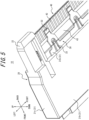
- FIG. 5 is an enlarged diagram of dash-dotted line enclosed part V in FIG. 2 .
- FIG. 6 is an external perspective diagram illustrating the first metal member 30 alone, in a top view.
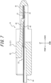
- FIG. 7 is a sectional diagram taken along line VII-VII in FIG. 2 .
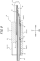
- FIG. 8 is a sectional diagram taken along line VIII-VIII in FIG. 2 .
- FIG. 9 is a sectional diagram taken along line IX-IX in FIG. 2 .
- the structure of the first connector 10 according to the embodiment will be mainly described below, with reference to FIGS. 2 and 5 to 9 .
- the first insulator 20 is a symmetrical box-shaped member obtained by injection molding an insulating and heat-resistant synthetic resin material.
- the first insulator 20 includes an outer peripheral wall 21 including four outer walls on the top, bottom, right, and left sides and shaped rectangular as a whole.
- the outer peripheral wall 21 includes a ceiling wall 21a, a bottom wall 21b, and a pair of side walls 21c.
- the first insulator 20 includes a protrusion portion 22 that protrudes from each side wall 21c toward the insertion side of the connection object 40 beyond the ceiling wall 21a and the bottom wall 21b.
- the first insulator 20 includes an insertion portion 23 surrounded by the outer peripheral wall 21 on the top, bottom, right, and left sides. As illustrated in FIG. 7 , the first insulator 20 includes a holding portion 24 recessed inside the protrusion portion 22. The first insulator 20 includes a locking portion 25 that extends from the central part of each side wall 21c in the front-back direction to the central part of the holding portion 24 in the front-back direction. The locking portion 25 is elastically deformable in the up-down direction. As illustrated in FIGS. 8 and 9 , the first insulator 20 includes an attachment portion 26 formed along the upper surface of the bottom wall 21b.
- the first metal member 30 includes a first base portion 31 that is plate-shaped in the front, back, right, and left directions.
- the first base portion 31 includes a first part 31a that is formed as a flat plate extending in the front, back, right, and left directions, and a second part 31b that bends obliquely upward from the back edge of the first part 31a and then extends horizontally.
- the first metal member 30 includes one or more first contact portions 32 each of which extends backward from the back edge of the first base portion 31, for example, the second part 31b.
- the first contact portion 32 bends obliquely upward from the back edge of the second part 31b and then extends horizontally at its back end.
- the first contact portion 32 is formed so as to be wide in the right-left direction from the part connected to the second part 31b to the center of the part extending obliquely upward and be tapered therefrom toward the tip.
- the first contact portion 32 is notched in the thickness direction at the center of the part wide in the right-left direction.
- the first contact portion 32 is elastically deformable in the up-down direction.
- the first metal member 30 includes one or more second contact portions 33 each of which is located forward from the first contact portion 32 and extends backward from the back of the first base portion 31, for example, the first part 31a.
- the second contact portion 33 linearly extends obliquely upward from the back of the first part 31a and bends upward at its back end.
- the second contact portion 33 is tapered so that the width in the right-left direction will continuously decrease from the part connected to the first part 31a to the back end.
- the whole second contact portion 33 fits in the second part 31b and the notch formed in the first contact portion 32 in the thickness direction.
- the back end of the second contact portion 33 is located in the notch formed in the first contact portion 32 in the thickness direction.
- the second contact portion 33 is elastically deformable in the up-down direction.
- a total of four pairs of the first contact portion 32 and the second contact portion 33 are formed in the first metal member 30, two pairs on each of the right and left sides.
- the pairs of the first contact portion 32 and the second contact portion 33 are arranged apart from each other in the right-left direction.
- the first contact portion 32 and the second contact portion 33 are linearly arranged in the front-back direction.
- the first metal member 30 includes a plurality of tip-up portions 34 arranged at regular intervals in the right-left direction in the central part of the first part 31a of the first base portion 31 in the front-back direction.
- Each tip-up portion 34 linearly extends obliquely upward from the first part 31a and bends upward at its back end.
- the tip-up portion 34 is tapered so that the width in the right-left direction will continuously decrease from the part connected to the first part 31a to the back end.
- the whole tip-up portion 34 is located above the notch formed in the first part 31a in the thickness direction.
- the tip-up portion 34 is elastically deformable in the up-down direction.
- the tip-up portion 34 is not located on the same straight line as the pair of the first contact portion 32 and the second contact portion 33 but located at a position different from the pair of the first contact portion 32 and the second contact portion 33 in the right-left direction.
- the first metal member 30 includes locking parts 35 formed at both of the right and left edges of the first part 31a of the first base portion 31.
- the first connector 10 is assembled by inserting the first metal member 30 backward into the first insulator 20 from the front side of the first insulator 20.
- the first metal member 30 is held by the first insulator 20 in a state of being attached to the attachment portion 26 of the first insulator 20.
- the functions of the first connector 10 when the first metal member 30 is attached to the first insulator 20 will be mainly described below.
- the locking parts 35 are fixed in the inner surfaces of the side walls 21c on the right and left.
- the back corners of the right and left edges of the first part 31a of the first base portion 31 face the forward-facing inner surfaces of the side walls 21c.
- the first metal member 30 is located along the bottom wall 21b of the first connector 10 substantially in the whole lower part of the first connector 10.
- the first part 31a of the first base portion 31 contacts the upper surface of the bottom wall 21b.
- the first contact portion 32 and the second contact portion 33 extend obliquely upward toward the back from the back end of the bottom wall 21b.
- the back end of the tip-up portion 34 is located inside the insertion portion 23.
- connection object 40 In a state in which the first metal member 30 is attached to the first insulator 20, the connection object 40 is inserted backward into the insertion portion 23 of the first insulator 20 from the front side of the insertion portion 23.
- the functions of the first connector 10 when the connection object 40 is inserted in the first insulator 20 and the first connector 10 is attached to the connection object 40 will be mainly described below.
- the holding portion 24 holds the connection object 40 in a state of accommodating the tip of the connection object 40.
- the locking portion 25 engages with the locked portion 45.
- the locking portion 25 thus functions as a retainer for the connection object 40 in the first connector 10 and prevents unintended removal of the connection object 40 from the first connector 10. In this way, the first connector 10 stably holds the connection object 40.
- the first contact portion 32 extends from the first base portion 31 toward the tip of the connection object 40 and contacts the plurality of contact lines 42.
- the second contact portion 33 is located more on the side opposite to the tip of the connection object 40 than the first contact portion 32 and contacts the first ground portion 43. The first contact portion 32 and the second contact portion 33 contact the connection object 40 in a state of being elastically deformed downward.
- the first contact portion 32 and the second contact portion 33 are located on the same side of the connection object 40 in the direction orthogonal to the extending direction of the plurality of contact lines 42. More specifically, the first contact portion 32 and the second contact portion 33 are located on the same side of the connection object 40 in the up-down direction which is orthogonal to both the extending direction of the plurality of contact lines 42 and the arrangement direction of the first contacts 70a and the second contacts 70b of the second connector 50.
- the first contact portion 32 contacts the part of each of the plurality of contact lines 42 adjacent to the boundary R between each contact line 42 and the first ground portion 43.
- the second contact portion 33 contacts the part of the first ground portion 43 adjacent to the boundary R.
- the first contact portion 32 and the second contact portion 33 are arranged linearly in the extending direction of the plurality of contact lines 42.
- one first contact portion 32 contacts a plurality of (i.e. two or more) contact lines 42.
- one first contact portion 32 contacts two contact lines 42 adjacent to each other in the right-left direction.
- the tip-up portion 34 extends backward from the first base portion 31 and contacts the first ground portion 43.
- the tip-up portion 34 is located more on the side opposite to the tip of the connection object 40 than the first contact portion 32 and the second contact portion 33.
- the tip-up portion 34 contacts the connection object 40 in a state of being elastically deformed downward.
- the tip-up portion 34 is located on the same side of the connection object 40 as the first contact portion 32 and the second contact portion 33 in the direction orthogonal to the extending direction of the plurality of contact lines 42.
- the tip-up portion 34 is not located on the same straight line in the extending direction of the plurality of contact lines 42 as the first contact portion 32 and the second contact portion 33 but located at a position different from the first contact portion 32 and the second contact portion 33 in the right-left direction.
- the second part 3 1b of the first base portion 31 extends backward from the first part 31a and contacts the first ground portion 43.
- the second part 31b is located more on the side opposite to the tip of the connection object 40 than the first contact portion 32 and the second contact portion 33.
- the second part 31b is located on the same side of the connection object 40 as the first contact portion 32 and the second contact portion 33 in the direction orthogonal to the extending direction of the plurality of contact lines 42.
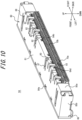
- FIG. 10 is an external perspective diagram illustrating the second connector 50 alone in FIG. 1 , in a top view from behind.
- FIG. 11 is an external perspective diagram illustrating the second connector 50 alone in FIG. 1 , in a top view from front.
- FIG. 12 is an exploded perspective diagram of the second connector 50 alone in FIG. 11 .
- the structure of the second connector 50 according to the embodiment will be described below, mainly with reference to FIGS. 10 to 12 .
- the second connector 50 is assembled by the following method as an example.
- the first contacts 70a and the second contacts 70b are press-fitted into the second insulator 60 from behind the second insulator 60.
- the second metal member 80 is press-fitted into the second insulator 60 so as to cover the whole second insulator 60 from above.
- the second connector 50 is mounted on the circuit board CB.
- the second connector 50 electrically connects the connection object 40 and the circuit board CB via the first contacts 70a and the second contacts 70b.
- the second insulator 60 is a symmetrical box-shaped member obtained by injection molding an insulating and heat-resistant synthetic resin material.
- the second insulator 60 is not limited to such and may be asymmetric in the right-left direction.
- the second insulator 60 includes an outer peripheral wall 61 including four outer walls on the top, bottom, right, and left sides and shaped rectangular as a whole.
- the outer peripheral wall 61 includes a ceiling wall 61a, a bottom wall 61b, and a pair of side walls 61c.
- the second insulator 60 includes a back wall 62 formed continuously with the ceiling wall 61a and the pair of side walls 61c. As illustrated in FIGS. 11 and 12 , the second insulator 60 includes an insertion portion 63 surrounded by the outer peripheral wall 61 on the top, bottom, right, and left sides. The front side of the insertion portion 63 is widely opened by the opening of the second insulator 60. The back side of the insertion portion 63 is closed by the back wall 62.
- the second insulator 60 includes first hole portions 64a passing through the ceiling wall 61a from the upper surface of the ceiling wall 61a to the insertion portion 63.
- Each first hole portion 64a extends linearly over substantially the whole ceiling wall 61a in the front-back direction.
- a total of four first hole portions 64a are formed in the ceiling wall 61a, two on each of the right and left sides. The first hole portions 64a are arranged apart from each other in the right-left direction.
- the second insulator 60 includes second hole portions 64b formed at both of the right and left ends of the ceiling wall 61a and passing through the ceiling wall 61a from the upper surface of the ceiling wall 61a to the insertion portion 63.
- a pair of second hole portions 64b are arranged on each of the right and left outer sides of the entire four first hole portions 64a.
- Each second hole portion 64b extends linearly over substantially the whole ceiling wall 61a in the front-back direction.
- the second insulator 60 includes a plurality of third hole portions 64c arranged apart from each other in the right-left direction, at the front edge of the ceiling wall 61a. As illustrated in FIG. 10 , the second insulator 60 includes a plurality of fourth hole portions 64d arranged apart from each other in the right-left direction, at the upper edge of the back wall 62.
- the second insulator 60 includes a plurality of contact installation grooves 65 recessed so as to extend in the front-back direction from the outer surface of the back wall 62 to the inside of the insertion portion 63.
- the plurality of contact installation grooves 65 are arranged in the right-left direction apart from each other at predetermined intervals.
- the contact installation grooves 65 include first contact installation grooves 65a and second contact installation grooves 65b.
- the first contact installation grooves 65a are arranged at positions corresponding to the number and installation positions of the first contacts 70a illustrated in FIG. 12 .
- the second contact installation grooves 65b are arranged at positions corresponding to the number and installation positions of the second contacts 70b illustrated in FIG. 12 .
- Each first contact 70a is obtained by forming a thin plate of a copper alloy or a corson copper alloy having spring elasticity, such as phosphor bronze, beryllium copper, or titanium copper, into the shape illustrated in FIG. 12 using progressive molding (stamping).
- the first contact 70a is formed only by punching.
- the working method for the first contact 70a is, however, not limited to such and may include, for example, bending in the thickness direction after punching.
- the surface of the first contact 70a is nickel-plated to form a base, and then plated with gold, tin, or the like as a surface layer plating.
- a total of eight first contacts 70a are arranged in the second connector 50, four on each of the right and left sides.
- Each first contact 70a includes a locking part 71a that is rectangular in shape and has a projection at its upper edge.
- the first contact 70a includes a mounted portion 72a extending backward in an L shape from the lower end of the locking part 71a.
- the first contact 70a includes a third contact portion 73a extending forward while being bent from the front end of the locking part 71a.
- the first contact 70a includes a sixth contact portion 74a located at the back edge of the locking part 71a.
- Each second contact 70b is obtained by forming a thin plate of a copper alloy or a corson copper alloy having spring elasticity, such as phosphor bronze, beryllium copper, or titanium copper, into the shape illustrated in FIG. 12 using progressive molding (stamping).
- the second contact 70b is formed only by punching.
- the working method for the second contact 70b is, however, not limited to such and may include, for example, bending in the thickness direction after punching.
- the surface of the second contact 70b is nickel-plated to form a base, and then plated with gold, tin, or the like as a surface layer plating.
- a plurality of second contacts 70b are arranged in the second connector 50 apart from each other in the right-left direction.
- Each second contact 70b includes a locking part 71b that is rectangular in shape and has a projection at its upper edge.
- the second contact 70b includes a mounted portion 72b extending backward in an L shape from the lower end of the locking part 71b.
- the second contact 70b includes a fourth contact portion 73b extending forward while being bent from the front end of the locking part 71b.
- the second metal member 80 is obtained by forming a thin plate of any metal material into the shape illustrated in FIG. 12 using progressive molding (stamping).
- the second metal member 80 is obtained by bending in the thickness direction after punching.
- the working method for the second metal member 80 is, however, not limited to such. For example, the working method may involve only punching.
- the second metal member 80 includes a second base portion 81 that forms the upper part of the second metal member 80 and is plate-shaped. As illustrated in FIG. 10 , the second metal member 80 includes a third base portion 82 that extends downward while being bent from the second base portion 81. The second metal member 80 includes a fifth contact portion 83 that linearly extends downward from the third base portion 82.
- the second metal member 80 includes a plurality of first claw portions 84a extending like a crank from the front edge of the second base portion 81.
- the plurality of first claw portions 84a are arranged apart from each other in the right-left direction.
- Each first claw portion 84a engages with the third hole portion 64c of the second insulator 60 in a state in which the second metal member 80 is attached to the second insulator 60.
- the second metal member 80 includes a plurality of second claw portions 84b protruding forward from the lower edge of the third base portion 82 so as to be folded back.
- the plurality of second claw portions 84b are arranged apart from each other in the right-left direction.
- Each second claw portion 84b engages with the fourth hole portion 64d of the second insulator 60 illustrated in FIG. 10 in a state in which the second metal member 80 is attached to the second insulator 60.
- the second metal member 80 includes a first locking part 85a extending downward in a U shape from each of the right and left ends of the back edge of the second base portion 81.
- the first locking part 85a is fixed in the back wall 62 of the second insulator 60 illustrated in FIG. 10 in a state in which the second metal member 80 is attached to the second insulator 60.
- the second metal member 80 includes a second locking part 85b extending downward while being bent from each of the right and left edges of the second base portion 81.
- the second locking part 85b is fixed in the side wall 61c of the second insulator 60 illustrated in FIG. 11 in a state in which the second metal member 80 is attached to the second insulator 60.
- the second metal member 80 includes a mounted portion 86 extending outward in the right-left direction while being bent from the front end of the lower edge of the second locking part 85b.
- the second metal member 80 includes a seventh contact portion 87 extending forward from the second base portion 81.
- the seventh contact portion 87 is bent in a U shape and then extends obliquely downward toward the front.
- Four seventh contact portions 87 are formed in the second metal member 80.
- the plurality of seventh contact portions 87 are arranged apart from each other in the right-left direction.
- Each seventh contact portion 87 is elastically deformable in the up-down direction.
- the second metal member 80 includes an engaging portion 88 linearly extending obliquely downward from each of the right and left ends of the second base portion 81.
- the engaging portion 88 is elastically deformable in the up-down direction.
- the second connector 50 is mounted on a circuit forming surface formed on the upper surface of the circuit board CB. More specifically, the mounted portion 72a of each first contact 70a is placed on a solder paste applied to a pattern on the circuit board CB. The mounted portion 72b of each second contact 70b is placed on a solder paste applied to a pattern on the circuit board CB. The mounted portion 86 of the second metal member 80 is placed on a solder paste applied to a pattern on the circuit board CB. Each solder paste is heated to melt in a reflow furnace or the like, to solder the mounted portions 72a, 72b, and 86 to the foregoing patterns. This completes mounting of the second connector 50 on the circuit board CB. Electronic components other than the second connector 50, such as a central processing unit (CPU), a controller, and memory, are mounted on the circuit forming surface of the circuit board CB.
- CPU central processing unit
- controller a controller
- memory are mounted on the circuit forming surface of the circuit board CB.
- FIG. 13 is a sectional diagram taken along line XIII-XIII in FIG. 1 .
- FIG. 14 is a sectional diagram taken along line XIV-XIV in FIG. 1 .
- FIG. 15 is a sectional diagram taken along line XV-XV in FIG. 1 .
- the protrusion portion 22 of the first insulator 20 is received in the insertion portion 63 of the second insulator 60.
- the engaging portion 88 of the second metal member 80 reaches the inside of the insertion portion 63 through the second hole portion 64b of the second insulator 60.
- the first contact 70a is attached to the second insulator 60 by being fixed in the first contact installation groove 65a of the second insulator 60.
- the third contact portion 73a of the first contact 70a contacts the first metal member 30. More specifically, the third contact portion 73a contacts the first contact portion 32 of the first metal member 30.
- the third contact portion 73a elastically deforms downward.
- the third contact portion 73a is located on the same side of the connection object 40 as the first contact portion 32 in the direction orthogonal to the extending direction of the plurality of contact lines 42.
- the fifth contact portion 83 of the second metal member 80 contacts the first contact 70a and extends from part of the second metal member 80 including the second base portion 81. As also illustrated in FIG. 10 , the fifth contact portion 83 contacts two first contacts 70a adjacent to each other in the right-left direction.
- the third base portion 82 of the second metal member 80 extends from the second base portion 81 while being bent to the first contact 70a side and lies along the end surface of the second insulator 60 in the extending direction of the plurality of contact lines 42.
- the sixth contact portion 74a of the first contact 70a contacts the fifth contact portion 83 of the second metal member 80.
- the third contact portion 73a and the sixth contact portion 74a are located at opposite ends of the first contact 70a in the extending direction of the plurality of contact lines 42.
- the first contact 70a contacts both the first metal member 30 of the first connector 10 and the second metal member 80 of the second connector 50.
- the first contact 70a is used for ground as an example.
- the second contact 70b is attached to the second insulator 60 by being fixed in the second contact installation groove 65b of the second insulator 60.
- the fourth contact portion 73b of the second contact 70b contacts the plurality of contact lines 42.
- the fourth contact portion 73b elastically deforms downward.
- the fourth contact portion 73b is located on the same side of the connection object 40 as the first contact portion 32 in the direction orthogonal to the extending direction of the plurality of contact lines 42.
- the second contact 70b directly contacts the plurality of contact lines 42 of the connection object 40.
- the second contact 70b is used for signals as an example.
- the seventh contact portion 87 of the second metal member 80 is located in the first hole portion 64a of the second insulator 60.
- the seventh contact portion 87 of the second metal member 80 contacts the connection object 40 and extends obliquely downward from the second base portion 81 while being bent in a U shape. More specifically, the seventh contact portion 87 contacts the second ground portion 44 of the connection object 40.
- the seventh contact portion 87 elastically deforms upward.
- the effects of the first connector 10 will be mainly described below. The same description applies to the connector module 1 including the first connector 10.
- the first contact portion 32 of the first metal member 30 contacts the plurality of contact lines 42 of the connection object 40, and the second contact portion 33 of the first metal member 30 contacts the first ground portion 43 of the connection object 40. Therefore, part of the plurality of contact lines 42 of the connection object 40 can be electrically connected to the first ground portion 43 via the first metal member 30.
- the contact line 42, the first metal member 30, and the first ground portion 43 thus stably function as one ground.
- crosstalk between the other contact lines 42 through which electrical signals are transmitted is suppressed.
- the first contact portion 32 and the second contact portion 33 are located on the same side of the connection object 40 in the direction orthogonal to the extending direction of the plurality of contact lines 42.
- all contact structures between the first metal member 30 and the connection object 40 can be located on the same side.
- the height of the first connector 10 can be reduced as compared with the case where the contact structures are located on both sides. As a result, the height of the whole connector module 1 can be reduced.
- first contact portion 32 and the second contact portion 33 contact the connection object 40 on the same side of the connection object 40, crosstalk between the plurality of contact lines 42 through which electrical signals are transmitted is suppressed as compared with the case where the contact structures are located on both of the upper and lower sides to contact the connection object 40.
- the first contact portion 32 contacts the part of each of the plurality of contact lines 42 adjacent to the boundary R, and the second contact portion 33 contacts the part of the first ground portion 43 adjacent to the boundary R. This can shorten the distance between the first contact portion 32 and the second contact portion 33.
- the contact part between the first metal member 30 and the contact line 42 and the contact part between the first metal member 30 and the first ground portion 43 are close to each other.
- the contact line 42, the first metal member 30, and the first ground portion 43 thus function as one ground more stably. Consequently, crosstalk between the other contact lines 42 through which electrical signals are transmitted is further suppressed, and the transmission characteristics in signal transmission are further improved.
- the first contact portion 32 and the second contact portion 33 are linearly arranged in the extending direction of the plurality of contact lines 42. This can shorten the distance between the first contact portion 32 and the second contact portion 33 as compared with the case where the first contact portion 32 and the second contact portion 33 are not located on the same straight line.
- the contact part between the first metal member 30 and the contact line 42 and the contact part between the first metal member 30 and the first ground portion 43 are close to each other.
- the contact line 42, the first metal member 30, and the first ground portion 43 thus function as one ground more stably. Consequently, crosstalk between the other contact lines 42 through which electrical signals are transmitted is further suppressed, and the transmission characteristics in signal transmission are further improved.
- the first contact portion 32 and the second contact portion 33 are elastically deformable and contact the connection object 40 in an elastically deformed state. This improves the contact reliability. For example, even when the connection object 40 vibrates, the first contact portion 32 and the second contact portion 33 deform elastically, as a result of which the contact with the connection object 40 is maintained more reliably. In addition, the tolerance of the thickness of the connection object 40 in the up-down direction can be absorbed when the connection object 40 is inserted into the first connector 10. Thus, the workability when inserting and holding the connection object 40 in the first connector 10 is improved. Moreover, the first connector 10 can improve the contact reliability with the connection object 40 as compared with the case where the first contact portion 32 and the second contact portion 33 are not elastically deformed. This improves the assemblability between the first connector 10 and the connection object 40. Consequently, the productivity when producing electronic devices by electrically connecting the connection object 40 and the circuit board CB via the connector module 1 is improved.
- One first contact portion 32 contacts a plurality of contact lines 42. This further ensures the contact between the first metal member 30 and the plurality of contact lines 42 of the connection object 40 and improves the robustness when the first metal member 30 and the plurality of contact lines 42 contact each other.
- the contact line 42, the first metal member 30, and the first ground portion 43 thus function as one ground more stably. Consequently, crosstalk between the other contact lines 42 through which electrical signals are transmitted is further suppressed.
- the first metal member 30 contacts the plurality of contact lines 42 and the first ground portion 43, so that the shielding effect of the first ground portion 43 of the connection object 40 can be extended to the plurality of contact lines 42.
- the contact line 42, the first metal member 30, and the first ground portion 43 function as one shield.
- the first contact 70a of the second connector 50 includes the third contact portion 73a that contacts the first metal member 30, so that the number of contacts as ground increases.
- the first contact 70a of the second connector 50 can also be electrically connected to the first ground portion 43 via the first metal member 30.
- the first contact 70a, the contact line 42, the first metal member 30, and the first ground portion 43 thus stably function as one ground. Consequently, crosstalk between the other contact lines 42 through which electrical signals are transmitted is further suppressed, and the transmission characteristics in signal transmission are further improved.
- the first contact 70a indirectly contacts the plurality of contact lines 42 via the third contact portion 73a and the first metal member 30. This makes it possible to easily change the spacing between the first contacts 70a in the right-left direction.
- the third contact portion 73a is located on the same side of the connection object 40 as the first contact portion 32 in the direction orthogonal to the extending direction of the plurality of contact lines 42.
- all contact structures between the first contact 70a and the first metal member 30 and contact structures between the first metal member 30 and the connection object 40 can be located on the same side.
- the height of the whole connector module 1 can be reduced as compared with the case where the contact structures are located on both sides.
- the second contact 70b includes the fourth contact portion 73b that contacts the plurality of contact lines 42, and the fourth contact portion 73b is located on the same side of the connection object 40 as the first contact portion 32 in the direction orthogonal to the extending direction of the plurality of contact lines 42.
- all contact structures between the second contact 70b and the connection object 40 and contact structures between the first metal member 30 and the connection object 40 can be located on the same side.
- the height of the whole connector module 1 can be reduced as compared with the case where the contact structures are located on both sides.
- the fifth contact portion 83 of the second metal member 80 contacts the first contact 70a and extends from part of the second metal member 80 including the second base portion 81, so that the number of contacts as ground increases.
- the second metal member 80 can also be electrically connected to the first ground portion 43 via the first contact 70a and the first metal member 30.
- the second metal member 80, the first contact 70a, the contact line 42, the first metal member 30, and the first ground portion 43 thus stably function as one ground. Consequently, crosstalk between the other contact lines 42 through which electrical signals are transmitted is further suppressed, and the transmission characteristics in signal transmission are further improved.
- the second metal member 80 is press-fitted into the second insulator 60 so as to cover the whole second insulator 60 from above, so that the outflow and inflow of noise for electrical signals are suppressed.
- electromagnetic noise generated from an electrical signal transmitted by the second contact 70b is prevented from flowing out of the second connector 50.
- electromagnetic noise generated from other electronic components arranged on the circuit board CB is prevented from flowing into the second connector 50.
- the fifth contact portion 83 extends from the third base portion 82 that extends from the second base portion 81 while being bent to the first contact 70a side and lies along the end surface of the second insulator 60 in the extending direction of the plurality of contact lines 42. This improves the robustness as the strength of the contact portion, as compared with the case where the fifth contact portion 83 extends directly from the second base portion 81. Therefore, the second metal member 80 and the first contact 70a can stably contact each other via the fifth contact portion 83.
- the second metal member 80, the first contact 70a, the contact line 42, the first metal member 30, and the first ground portion 43 thus function as one ground more stably. Consequently, crosstalk between the other contact lines 42 through which electrical signals are transmitted is further suppressed, and the transmission characteristics in signal transmission are further improved.
- the third contact portion 73a and the sixth contact portion 74a are located at opposite ends of the first contact 70a in the extending direction of the plurality of contact lines 42. This enables stable contact of the first contacts 70a with both the first metal member 30 of the first connector 10 and the second metal member 80 of the second connector 50. Therefore, the first metal member 30 and the second metal member 80 can be electrically connected to each other stably via the first contact 70a.
- the second metal member 80, the first contact 70a, the contact line 42, the first metal member 30, and the first ground portion 43 thus function as one ground more stably. Consequently, crosstalk between the other contact lines 42 through which electrical signals are transmitted is further suppressed, and the transmission characteristics in signal transmission are further improved.
- the seventh contact portion 87 of the second metal member 80 extends from the second base portion 81 and contacts the connection object 40, so that the number of contacts as ground increases.
- the second metal member 80 is electrically connected to the first ground portion 43 of the connection object 40 via the fifth contact portion 83 and also electrically connected to the second ground portion 44 of the connection object 40 via the seventh contact portion 87. Therefore, the second ground portion 44 can also be electrically connected to the first ground portion 43 via the second metal member 80, the first contact 70a, and the first metal member 30.
- the second ground portion 44, the second metal member 80, the first contact 70a, the contact line 42, the first metal member 30, and the first ground portion 43 thus stably function as one ground. Consequently, crosstalk between the other contact lines 42 through which electrical signals are transmitted is further suppressed, and the transmission characteristics in signal transmission are further improved.
- the seventh contact portion 87 is elastically deformable. This improves the contact reliability. For example, even when the connection object 40 vibrates, the seventh contact portion 87 deforms elastically, as a result of which the contact with the connection object 40 is maintained more reliably. In addition, the tolerance of the thickness of the connection object 40 in the up-down direction can be absorbed when the connection object 40 is inserted into the second connector 50. Thus, the workability when inserting the connection object 40 held by the first connector 10 into the second connector 50 is improved. Moreover, the second connector 50 can hold the connection object 40 more stably than in the case where the seventh contact portion 87 is not elastically deformed. The second connector 50 can also improve the contact reliability with the connection object 40. This improves the assemblability between the second connector 50 and the connection object 40. Consequently, the productivity when producing electronic devices by electrically connecting the connection object 40 and the circuit board CB via the connector module 1 is improved.
- the shape, position, orientation, and number of each component described above are not limited to those in the above description and the illustration in the drawings.
- the shape, position, orientation, and number of each component may be freely set as long as its functions can be achieved.
- the method of assembling the first connector 10 is not limited to the foregoing method.
- the method of assembling the first connector 10 may be any method with which each function can be achieved.
- the first metal member 30 may be integrally formed with the first insulator 20 by insert molding, instead of press fitting.
- the method of assembling the second connector 50 is not limited to the foregoing method.
- the method of assembling the second connector 50 may be any method with which each function can be achieved.
- at least one of the first contact 70a, the second contact 70b, and the second metal member 80 may be integrally formed with the second insulator 60 by insert molding, instead of press fitting.
- first contact portion 32 and the second contact portion 33 are located on the same side of the connection object 40 in the direction orthogonal to the extending direction of the plurality of contact lines 42, the present disclosure is not limited to such.
- the first contact portion 32 and the second contact portion 33 may be located on different sides of the connection object 40.
- first contact portion 32 contacts the part of each of the plurality of contact lines 42 adjacent to the boundary R and the second contact portion 33 contacts the part of the first ground portion 43 adjacent to the boundary R
- present disclosure is not limited to such.
- the first contact portion 32 may contact any part of the plurality of contact lines 42, and the second contact portion 33 may contact any part of the first ground portion 43.
- first contact portion 32 and the second contact portion 33 are arranged linearly in the extending direction of the plurality of contact lines 42
- present disclosure is not limited to such.
- the first contact portion 32 and the second contact portion 33 may be arranged not on the same straight line but on different straight lines in the extending direction of the plurality of contact lines 42.
- first contact portion 32 and the second contact portion 33 are elastically deformable and contact the connection object 40 in an elastically deformed state
- the present disclosure is not limited to such. Only one of the first contact portion 32 and the second contact portion 33 may be elastically deformable, or neither of them may be elastically deformable.
- One first contact portion 32 may contact three or more contact lines 42, or contact only one contact line 42.
- first contact portion 32 and the second contact portion 33 are formed in the first metal member 30, two pairs on each of the right and left sides, as illustrated in FIG. 6
- present disclosure is not limited to such. Any numbers of first contact portions 32 and second contact portions 33 may be formed at any other positions different from the positions illustrated in FIG. 6 .
- the present disclosure is not limited to such.
- the first contact 70a may contact, for example, the plurality of contact lines 42 of the connection object 40, instead of contacting the first metal member 30.
- the first contact 70a may be used not for ground but for signals.
- the present disclosure is not limited to such.
- the first contact portion 32 and the third contact portion 73a may be located on different sides of the connection object 40.
- the fourth contact portion 73b is located on the same side of the connection object 40 as the first contact portion 32 in the direction orthogonal to the extending direction of the plurality of contact lines 42, the present disclosure is not limited to such.
- the first contact portion 32 and the fourth contact portion 73b may be located on different sides of the connection object 40.
- the second metal member 80 includes the fifth contact portion 83 that contacts the first contact 70a and extends from part of the second metal member 80 including the second base portion 81
- the second metal member 80 may not contact the first contact 70a.
- the fifth contact portion 83 contacts two first contacts 70a adjacent to each other in the right-left direction
- the present disclosure is not limited to such.
- the fifth contact portion 83 may contact one first contact 70a or three or more first contacts 70a.
- the present disclosure is not limited to such.
- the fifth contact portion 83 may directly extend from the second base portion 81.
- the present disclosure is not limited to such.
- the third contact portion 73a and the sixth contact portion 74a may be formed at any positions in the first contact 70a.
- the second metal member 80 includes the elastically deformable seventh contact portion 87 that extends from the second base portion 81 and contacts the connection object 40
- the seventh contact portion 87 may not be elastically deformable.
- the second metal member 80 may not include the seventh contact portion 87 and may not contact the connection object 40.
- first contacts 70a and the second contacts 70b may be arranged in any way.
- one first contact 70a may be provided between a plurality of second contacts 70b, or first contacts 70a and second contacts 70b may be arranged alternately.
- FIG. 16 is an external perspective diagram illustrating a first metal member 30 alone according to a modification, in a top view.
- the structure of the first metal member 30 according to the modification will be described below with reference to FIG. 16 , mainly focusing on the differences from FIG. 6 .
- the first contact portion 32 may not be notched in the thickness direction at the center of the part formed wide in the right-left direction, unlike in the first metal member 30 in FIG. 6 .
- the length in the front-back direction of the back end of the first contact portion 32 extending horizontally may be shorter than that of the first contact portion 32 of the first metal member 30 in FIG. 6 .
- the second contact portion 33 may be formed as a projection that is located at the center of the part formed wide in the right-left direction in the first contact portion 32 and protrudes from the surface of the first contact portion 32.
- the second contact portion 33 may protrude from the surface of the first contact portion 32 so as to be circular in a top view.
- FIG. 17 is a sectional diagram corresponding to FIG. 14 and illustrating a connector module 1 according to the modification.
- the foregoing embodiment describes the case where the third contact portion 73a of the first contact 70a contacts the first metal member 30, the present disclosure is not limited to such.
- the third contact portion 73a of the first contact 70a may contact the plurality of contact lines 42 which the first contact portion 32 contacts.
- the elastic deformation of the first contact 70a is reduced by the thickness of the first metal member 30 as compared with the case illustrated in FIG. 14 .
- the first contact 70a can be kept from being greatly deformed or bent and can be prevented from buckling.
- burrs of the first metal member 30 caused as a result of the tip of the first contact portion 32 of the first metal member 30 contacting the third contact portion 73a of the first contact 70a when the connection object 40 held by the first connector 10 is inserted into the second connector 50 can be prevented.
- the above-described first connector 10 or connector module 1 is mounted in an electronic device.
- the electronic device include any information devices such as a personal computer, a game machine, a copier, a printer, a facsimile machine, and a multifunction machine.
- Examples of the electronic device include any acoustic video devices such as a liquid crystal television, a recorder, a camera, and headphones. The electronic device is not limited to such.
- Examples of the electronic device include any on-vehicle devices such as a camera, a radar, a drive recorder, and an engine control unit.
- Examples of the electronic device include any on-vehicle devices used in vehicle-mounted systems such as a car navigation system, an advanced driving support system, and a security system.
- Examples of the electronic device include any industrial devices.
Landscapes
- Coupling Device And Connection With Printed Circuit (AREA)
- Details Of Connecting Devices For Male And Female Coupling (AREA)
Abstract
Description
- This application claims priority to and the benefit of
Japanese Patent Application No. 2021-178123 filed on October 29, 2021 - The present disclosure relates to a first connector and a connector module.
- In recent years, the speed of signal transmission has been increasing in electronic devices, including information processing devices such as personal computers (PCs), industrial devices, and on-vehicle devices. Connectors for electrically connecting flexible flat cables (FFCs), flexible printed circuit boards (FPCs), and the like to circuit boards are also required to be designed for high-speed transmission.
- For example,
PTL 1 discloses an electrical connector that enables good electromagnetic shielding of signal transmission paths without additional operations. - PTL 1:
JP 2019-110089 A - A first connector according to an embodiment of the present disclosure is a first connector configured to be attached to a connection object that includes a plurality of contact lines exposed at a tip of the connection object and a ground portion covering part of the plurality of contact lines, the first connector comprising: a first insulator including a holding portion configured to hold the connection object in a state of accommodating the tip; and a first metal member attached to the first insulator, wherein the first metal member includes: a first base portion that is plate-shaped; a first contact portion configured to extend from the first base portion toward the tip and contact the plurality of contact lines; and a second contact portion configured to be located more on a side opposite to the tip than the first contact portion and contact the ground portion.
- A connector module according to an embodiment of the present disclosure is a connector module comprising: the foregoing first connector; and a second connector configured to be fitted to the first connector, wherein the second connector includes: a second insulator configured to be fitted to the first insulator; and a first contact attached to the second insulator, and the first contact includes a third contact portion configured to contact the first metal member.
- A connector module according to an embodiment of the present disclosure is a connector module comprising: the foregoing first connector; and a second connector configured to be fitted to the first connector, wherein the second connector includes: a second insulator configured to be fitted to the first insulator; and a first contact attached to the second insulator, and the first contact includes a third contact portion configured to contact the plurality of contact lines which the first contact portion is configured to contact.
- In the accompanying drawings:
-
FIG. 1 is an external perspective diagram illustrating a connector module according to an embodiment in a state in which a first connector holding a connection object and a second connector are connected to each other, in a top view; -
FIG. 2 is an external perspective diagram illustrating the first connector inFIG. 1 holding the connection object, in a bottom view; -
FIG. 3 is an external perspective diagram illustrating the connection object in a state of not being held by the first connector, in a top view; -
FIG. 4 is an external perspective diagram illustrating the connection object in a state of not being held by the first connector, in a bottom view; -
FIG. 5 is an enlarged diagram of dash-dotted line enclosed part V inFIG. 2 ; -
FIG. 6 is an external perspective diagram illustrating a first metal member alone, in a top view; -
FIG. 7 is a sectional diagram taken along line VII-VII inFIG. 2 ; -
FIG. 8 is a sectional diagram taken along line VIII-VIII inFIG. 2 ; -
FIG. 9 is a sectional diagram taken along line IX-IX inFIG. 2 ; -
FIG. 10 is an external perspective diagram illustrating the second connector alone inFIG. 1 , in a top view from behind; -
FIG. 11 is an external perspective diagram illustrating the second connector alone inFIG. 1 , in a top view from front; -
FIG. 12 is an exploded perspective diagram of the second connector alone inFIG. 11 ; -
FIG. 13 is a sectional diagram taken along line XIII-XIII inFIG. 1 ; -
FIG. 14 is a sectional diagram taken along line XIV-XIV inFIG. 1 ; -
FIG. 15 is a sectional diagram taken along line XV-XV inFIG. 1 ; -
FIG. 16 is an external perspective diagram illustrating a first metal member alone according to a modification, in a top view; and -
FIG. 17 is a sectional diagram corresponding toFIG. 14 and illustrating a connector module according to the modification. - For the electrical connector described in
PTL 1, improvement in transmission characteristics in signal transmission, including suppression of crosstalk, under high-speed transmission standards such as Universal Serial Bus (USB) 4.0 is not fully considered. - With a first connector and a connector module according to an embodiment of the present disclosure, it is possible to obtain good transmission characteristics in signal transmission.
- An embodiment of the present disclosure will be described in detail below, with reference to the attached drawings. The directions such as front, back, right, left, up (top), and down (bottom) in the following description are based on the directions of the arrows in the drawings. The directions of the arrows are consistent throughout the drawings. In some drawings, the below-described circuit board CB is omitted for the sake of simplicity.
-
FIG. 1 is an external perspective diagram illustrating aconnector module 1 according to an embodiment in a state in which afirst connector 10 holding aconnection object 40 and asecond connector 50 are connected to each other, in a top view.FIG. 2 is an external perspective diagram illustrating thefirst connector 10 inFIG. 1 holding theconnection object 40, in a bottom view. The structures of theconnector module 1 and thefirst connector 10 according to the embodiment will be mainly described below, with reference toFIGS. 1 and2 . - The
connector module 1 includes thefirst connector 10 and thesecond connector 50 connectable to each other. - The
second connector 50 according to the embodiment is mounted on the circuit board CB. The circuit board CB may be a rigid board, or any circuit board other than a rigid board. Thesecond connector 50 electrically connects theconnection object 40 inserted in thesecond connector 50 together with thefirst connector 10 and the circuit board CB. Theconnection object 40 can be inserted into and removed from thesecond connector 50 via thefirst connector 10. Thesecond connector 50 is connected to theconnection object 40 in a state in which theconnection object 40 is inserted. - The
second connector 50 includes asecond insulator 60, one or morefirst contacts 70a, one or moresecond contacts 70b, and asecond metal member 80. Thefirst contacts 70a, thesecond contacts 70b, and thesecond metal member 80 are attached to thesecond insulator 60. - The
first connector 10 holds theconnection object 40. For example, thefirst connector 10 receives theconnection object 40 inserted backward from the front and supports the right and left ends of theconnection object 40 to hold thewhole connection object 40. - The
connection object 40 held by thefirst connector 10 is, for example, an FFC. Theconnection object 40 is, however, not limited to this, and may be any cable that is electrically connected to the circuit board CB via thefirst connector 10 and thesecond connector 50. For example, theconnection object 40 may be an FPC. Theconnection object 40 is not limited to cables as described above and may include any object. For example, theconnection object 40 may include a rigid board or any other circuit board. - The
first connector 10 can be connected to thesecond connector 50 in a state of holding theconnection object 40. Thefirst connector 10 includes afirst insulator 20 that is fitted to thesecond insulator 60 in a connected state in which thefirst connector 10 and thesecond connector 50 are connected to each other. Thefirst connector 10 includes afirst metal member 30 attached to thefirst insulator 20. - The
connection object 40 contacts thesecond contacts 70b in a fitted state in which thefirst insulator 20 and thesecond insulator 60 are fitted to each other. Thefirst metal member 30 contacts thefirst contacts 70a in a fitted state in which thefirst insulator 20 and thesecond insulator 60 are fitted to each other. - In the following description, for example, it is assumed that the
second connector 50 according to the embodiment is a receptacle connector, that thefirst connector 10 is a plug connector, that thesecond connector 50 in which thefirst contacts 70a and thesecond contacts 70b elastically deform in a fitted state in which thefirst insulator 20 and thesecond insulator 60 are fitted to each other is a receptacle connector, and that thefirst connector 10 holding theconnection object 40 in the fitted state is a plug connector. The types of thefirst connector 10 and thesecond connector 50 are not limited to such. For example, thesecond connector 50 may serve as a plug connector and thefirst connector 10 as a receptacle connector. - In the following description, it is assumed that the
connection object 40 is inserted into thesecond connector 50 in a direction parallel to the circuit board CB on which thesecond connector 50 is mounted. For example, theconnection object 40 is inserted into thesecond connector 50 in the front-back direction. The insertion direction is not limited to such. Theconnection object 40 may be inserted into thesecond connector 50 in a direction orthogonal to the circuit board CB on which thesecond connector 50 is mounted. Theconnection object 40 may be inserted into thesecond connector 50 in the up-down direction. - Herein, the term "extending direction of the plurality of contact lines" means the front-back direction as an example. The term "insertion/removal direction" means the front-back direction as an example. The term "direction orthogonal to the extending direction of the plurality of contact lines" means the up-down direction as an example. The term "tip of the connection object" means the back tip of the connection object as an example. The term "removal side" means the front side as an example. The term "insertion side" means the back side as an example.
-
FIG. 3 is an external perspective diagram illustrating theconnection object 40 in a state of not being held by thefirst connector 10, in a top view.FIG. 4 is an external perspective diagram illustrating theconnection object 40 in a state of not being held by thefirst connector 10, in a bottom view. The structure of theconnection object 40 that is held by thefirst connector 10 will be mainly described below, with reference toFIGS. 3 and4 . - The
connection object 40 has a stack structure formed by bonding a plurality of thin film materials to each other. Theconnection object 40 includes areinforcement portion 41 constituting a tip part in the extending direction of theconnection object 40, i.e. the insertion/removal direction in which theconnection object 40 is inserted and removed, and harder than other parts. Theconnection object 40 includes a plurality ofcontact lines 42 linearly extending in the insertion/removal direction to the tip of thereinforcement portion 41. Eachcontact line 42 is exposed downward at the tip of theconnection object 40. - The
connection object 40 includes afirst ground portion 43 that covers part of the plurality ofcontact lines 42 with the lower outermost layer on the removal side of theconnection object 40. Thefirst ground portion 43 extends in a flat plate shape from the front toward the back and is bent obliquely upward at its tip. Theconnection object 40 includes asecond ground portion 44 that covers substantially the whole contact lines 42 with the upper outermost layer. Thesecond ground portion 44 extends in a flat plate shape from the front toward the back and is bent obliquely upward at the front edge of thereinforcement portion 41 and stacked on thereinforcement portion 41 at its tip part. - The
connection object 40 includes a lockedportion 45 formed by notching, inward in the right-left direction, the center of each edge extending in the front-back direction of the tip part of theconnection object 40 including thereinforcement portion 41. The lockedportion 45 is formed on both of the right and left sides in the tip part of theconnection object 40 including thereinforcement portion 41. -
FIG. 5 is an enlarged diagram of dash-dotted line enclosed part V inFIG. 2 .FIG. 6 is an external perspective diagram illustrating thefirst metal member 30 alone, in a top view.FIG. 7 is a sectional diagram taken along line VII-VII inFIG. 2 .FIG. 8 is a sectional diagram taken along line VIII-VIII inFIG. 2 .FIG. 9 is a sectional diagram taken along line IX-IX inFIG. 2 . The structure of thefirst connector 10 according to the embodiment will be mainly described below, with reference toFIGS. 2 and5 to 9 . - The
first insulator 20 is a symmetrical box-shaped member obtained by injection molding an insulating and heat-resistant synthetic resin material. Thefirst insulator 20 includes an outerperipheral wall 21 including four outer walls on the top, bottom, right, and left sides and shaped rectangular as a whole. The outerperipheral wall 21 includes aceiling wall 21a, abottom wall 21b, and a pair ofside walls 21c. As illustrated inFIG. 5 , thefirst insulator 20 includes aprotrusion portion 22 that protrudes from eachside wall 21c toward the insertion side of theconnection object 40 beyond theceiling wall 21a and thebottom wall 21b. - As illustrated in
FIGS. 7 to 9 , thefirst insulator 20 includes aninsertion portion 23 surrounded by the outerperipheral wall 21 on the top, bottom, right, and left sides. As illustrated inFIG. 7 , thefirst insulator 20 includes a holdingportion 24 recessed inside theprotrusion portion 22. Thefirst insulator 20 includes a lockingportion 25 that extends from the central part of eachside wall 21c in the front-back direction to the central part of the holdingportion 24 in the front-back direction. The lockingportion 25 is elastically deformable in the up-down direction. As illustrated inFIGS. 8 and9 , thefirst insulator 20 includes anattachment portion 26 formed along the upper surface of thebottom wall 21b. - The
first metal member 30 is obtained by forming a thin plate of any metal material into the shape illustrated inFIG. 6 using progressive molding (stamping). Thefirst metal member 30 is obtained by bending in the thickness direction after punching. The working method for thefirst metal member 30 is, however, not limited to such. For example, the working method may involve only punching. The surface of thefirst metal member 30 is nickel-plated to form a base, and then plated with gold, tin, or the like as a surface layer plating. Plating including nickel plating and surface layer plating may be partially applied to required parts. - The
first metal member 30 includes afirst base portion 31 that is plate-shaped in the front, back, right, and left directions. Thefirst base portion 31 includes afirst part 31a that is formed as a flat plate extending in the front, back, right, and left directions, and asecond part 31b that bends obliquely upward from the back edge of thefirst part 31a and then extends horizontally. - The
first metal member 30 includes one or morefirst contact portions 32 each of which extends backward from the back edge of thefirst base portion 31, for example, thesecond part 31b. Thefirst contact portion 32 bends obliquely upward from the back edge of thesecond part 31b and then extends horizontally at its back end. Thefirst contact portion 32 is formed so as to be wide in the right-left direction from the part connected to thesecond part 31b to the center of the part extending obliquely upward and be tapered therefrom toward the tip. Thefirst contact portion 32 is notched in the thickness direction at the center of the part wide in the right-left direction. Thefirst contact portion 32 is elastically deformable in the up-down direction. - The
first metal member 30 includes one or moresecond contact portions 33 each of which is located forward from thefirst contact portion 32 and extends backward from the back of thefirst base portion 31, for example, thefirst part 31a. As illustrated inFIG. 8 , thesecond contact portion 33 linearly extends obliquely upward from the back of thefirst part 31a and bends upward at its back end. Thesecond contact portion 33 is tapered so that the width in the right-left direction will continuously decrease from the part connected to thefirst part 31a to the back end. The wholesecond contact portion 33 fits in thesecond part 31b and the notch formed in thefirst contact portion 32 in the thickness direction. The back end of thesecond contact portion 33 is located in the notch formed in thefirst contact portion 32 in the thickness direction. Thesecond contact portion 33 is elastically deformable in the up-down direction. - A total of four pairs of the
first contact portion 32 and thesecond contact portion 33 are formed in thefirst metal member 30, two pairs on each of the right and left sides. The pairs of thefirst contact portion 32 and thesecond contact portion 33 are arranged apart from each other in the right-left direction. Thefirst contact portion 32 and thesecond contact portion 33 are linearly arranged in the front-back direction. - The
first metal member 30 includes a plurality of tip-upportions 34 arranged at regular intervals in the right-left direction in the central part of thefirst part 31a of thefirst base portion 31 in the front-back direction. Each tip-upportion 34 linearly extends obliquely upward from thefirst part 31a and bends upward at its back end. The tip-upportion 34 is tapered so that the width in the right-left direction will continuously decrease from the part connected to thefirst part 31a to the back end. The whole tip-upportion 34 is located above the notch formed in thefirst part 31a in the thickness direction. The tip-upportion 34 is elastically deformable in the up-down direction. The tip-upportion 34 is not located on the same straight line as the pair of thefirst contact portion 32 and thesecond contact portion 33 but located at a position different from the pair of thefirst contact portion 32 and thesecond contact portion 33 in the right-left direction. - The
first metal member 30 includes lockingparts 35 formed at both of the right and left edges of thefirst part 31a of thefirst base portion 31. - As illustrated in
FIGS. 2 ,5 , and7 to 9 , thefirst connector 10 is assembled by inserting thefirst metal member 30 backward into thefirst insulator 20 from the front side of thefirst insulator 20. Thefirst metal member 30 is held by thefirst insulator 20 in a state of being attached to theattachment portion 26 of thefirst insulator 20. - The functions of the
first connector 10 when thefirst metal member 30 is attached to thefirst insulator 20 will be mainly described below. - When the
first metal member 30 is attached to thefirst insulator 20, the lockingparts 35 are fixed in the inner surfaces of theside walls 21c on the right and left. The back corners of the right and left edges of thefirst part 31a of thefirst base portion 31 face the forward-facing inner surfaces of theside walls 21c. - As illustrated in
FIGS. 8 and9 , thefirst metal member 30 is located along thebottom wall 21b of thefirst connector 10 substantially in the whole lower part of thefirst connector 10. Thefirst part 31a of thefirst base portion 31 contacts the upper surface of thebottom wall 21b. Thefirst contact portion 32 and thesecond contact portion 33 extend obliquely upward toward the back from the back end of thebottom wall 21b. The back end of the tip-upportion 34 is located inside theinsertion portion 23. - In a state in which the
first metal member 30 is attached to thefirst insulator 20, theconnection object 40 is inserted backward into theinsertion portion 23 of thefirst insulator 20 from the front side of theinsertion portion 23. The functions of thefirst connector 10 when theconnection object 40 is inserted in thefirst insulator 20 and thefirst connector 10 is attached to theconnection object 40 will be mainly described below. - As illustrated in
FIG. 7 , when theconnection object 40 is inserted in theinsertion portion 23 and thefirst connector 10 is attached to theconnection object 40, the holdingportion 24 holds theconnection object 40 in a state of accommodating the tip of theconnection object 40. The lockingportion 25 engages with the lockedportion 45. The lockingportion 25 thus functions as a retainer for theconnection object 40 in thefirst connector 10 and prevents unintended removal of theconnection object 40 from thefirst connector 10. In this way, thefirst connector 10 stably holds theconnection object 40. - As illustrated in
FIG. 8 , thefirst contact portion 32 extends from thefirst base portion 31 toward the tip of theconnection object 40 and contacts the plurality of contact lines 42. Thesecond contact portion 33 is located more on the side opposite to the tip of theconnection object 40 than thefirst contact portion 32 and contacts thefirst ground portion 43. Thefirst contact portion 32 and thesecond contact portion 33 contact theconnection object 40 in a state of being elastically deformed downward. - The
first contact portion 32 and thesecond contact portion 33 are located on the same side of theconnection object 40 in the direction orthogonal to the extending direction of the plurality of contact lines 42. More specifically, thefirst contact portion 32 and thesecond contact portion 33 are located on the same side of theconnection object 40 in the up-down direction which is orthogonal to both the extending direction of the plurality ofcontact lines 42 and the arrangement direction of thefirst contacts 70a and thesecond contacts 70b of thesecond connector 50. Thefirst contact portion 32 contacts the part of each of the plurality ofcontact lines 42 adjacent to the boundary R between eachcontact line 42 and thefirst ground portion 43. Thesecond contact portion 33 contacts the part of thefirst ground portion 43 adjacent to the boundary R. Thefirst contact portion 32 and thesecond contact portion 33 are arranged linearly in the extending direction of the plurality of contact lines 42. - As illustrated in
FIG. 5 , onefirst contact portion 32 contacts a plurality of (i.e. two or more) contact lines 42. For example, onefirst contact portion 32 contacts twocontact lines 42 adjacent to each other in the right-left direction. - As illustrated in
FIG. 9 , the tip-upportion 34 extends backward from thefirst base portion 31 and contacts thefirst ground portion 43. The tip-upportion 34 is located more on the side opposite to the tip of theconnection object 40 than thefirst contact portion 32 and thesecond contact portion 33. The tip-upportion 34 contacts theconnection object 40 in a state of being elastically deformed downward. - The tip-up
portion 34 is located on the same side of theconnection object 40 as thefirst contact portion 32 and thesecond contact portion 33 in the direction orthogonal to the extending direction of the plurality of contact lines 42. The tip-upportion 34 is not located on the same straight line in the extending direction of the plurality ofcontact lines 42 as thefirst contact portion 32 and thesecond contact portion 33 but located at a position different from thefirst contact portion 32 and thesecond contact portion 33 in the right-left direction. - The second part 3 1b of the
first base portion 31 extends backward from thefirst part 31a and contacts thefirst ground portion 43. Thesecond part 31b is located more on the side opposite to the tip of theconnection object 40 than thefirst contact portion 32 and thesecond contact portion 33. Thesecond part 31b is located on the same side of theconnection object 40 as thefirst contact portion 32 and thesecond contact portion 33 in the direction orthogonal to the extending direction of the plurality of contact lines 42. -
FIG. 10 is an external perspective diagram illustrating thesecond connector 50 alone inFIG. 1 , in a top view from behind.FIG. 11 is an external perspective diagram illustrating thesecond connector 50 alone inFIG. 1 , in a top view from front.FIG. 12 is an exploded perspective diagram of thesecond connector 50 alone inFIG. 11 . The structure of thesecond connector 50 according to the embodiment will be described below, mainly with reference toFIGS. 10 to 12 . - The
second connector 50 is assembled by the following method as an example. Thefirst contacts 70a and thesecond contacts 70b are press-fitted into thesecond insulator 60 from behind thesecond insulator 60. Thesecond metal member 80 is press-fitted into thesecond insulator 60 so as to cover the wholesecond insulator 60 from above. With reference toFIG. 1 , thesecond connector 50 is mounted on the circuit board CB. Thesecond connector 50 electrically connects theconnection object 40 and the circuit board CB via thefirst contacts 70a and thesecond contacts 70b. - As illustrated in
FIG. 12 , thesecond insulator 60 is a symmetrical box-shaped member obtained by injection molding an insulating and heat-resistant synthetic resin material. Thesecond insulator 60 is not limited to such and may be asymmetric in the right-left direction. Thesecond insulator 60 includes an outerperipheral wall 61 including four outer walls on the top, bottom, right, and left sides and shaped rectangular as a whole. The outerperipheral wall 61 includes aceiling wall 61a, abottom wall 61b, and a pair ofside walls 61c. - As illustrated in
FIG. 10 , thesecond insulator 60 includes aback wall 62 formed continuously with theceiling wall 61a and the pair ofside walls 61c. As illustrated inFIGS. 11 and12 , thesecond insulator 60 includes aninsertion portion 63 surrounded by the outerperipheral wall 61 on the top, bottom, right, and left sides. The front side of theinsertion portion 63 is widely opened by the opening of thesecond insulator 60. The back side of theinsertion portion 63 is closed by theback wall 62. - As illustrated in
FIG. 12 , thesecond insulator 60 includesfirst hole portions 64a passing through theceiling wall 61a from the upper surface of theceiling wall 61a to theinsertion portion 63. Eachfirst hole portion 64a extends linearly over substantially thewhole ceiling wall 61a in the front-back direction. A total of fourfirst hole portions 64a are formed in theceiling wall 61a, two on each of the right and left sides. Thefirst hole portions 64a are arranged apart from each other in the right-left direction. - The
second insulator 60 includessecond hole portions 64b formed at both of the right and left ends of theceiling wall 61a and passing through theceiling wall 61a from the upper surface of theceiling wall 61a to theinsertion portion 63. A pair ofsecond hole portions 64b are arranged on each of the right and left outer sides of the entire fourfirst hole portions 64a. Eachsecond hole portion 64b extends linearly over substantially thewhole ceiling wall 61a in the front-back direction. - The
second insulator 60 includes a plurality ofthird hole portions 64c arranged apart from each other in the right-left direction, at the front edge of theceiling wall 61a. As illustrated inFIG. 10 , thesecond insulator 60 includes a plurality offourth hole portions 64d arranged apart from each other in the right-left direction, at the upper edge of theback wall 62. - As illustrated in
FIGS. 11 and12 , thesecond insulator 60 includes a plurality ofcontact installation grooves 65 recessed so as to extend in the front-back direction from the outer surface of theback wall 62 to the inside of theinsertion portion 63. The plurality ofcontact installation grooves 65 are arranged in the right-left direction apart from each other at predetermined intervals. Thecontact installation grooves 65 include firstcontact installation grooves 65a and secondcontact installation grooves 65b. The firstcontact installation grooves 65a are arranged at positions corresponding to the number and installation positions of thefirst contacts 70a illustrated inFIG. 12 . The secondcontact installation grooves 65b are arranged at positions corresponding to the number and installation positions of thesecond contacts 70b illustrated inFIG. 12 . - Each
first contact 70a is obtained by forming a thin plate of a copper alloy or a corson copper alloy having spring elasticity, such as phosphor bronze, beryllium copper, or titanium copper, into the shape illustrated inFIG. 12 using progressive molding (stamping). Thefirst contact 70a is formed only by punching. The working method for thefirst contact 70a is, however, not limited to such and may include, for example, bending in the thickness direction after punching. The surface of thefirst contact 70a is nickel-plated to form a base, and then plated with gold, tin, or the like as a surface layer plating. A total of eightfirst contacts 70a are arranged in thesecond connector 50, four on each of the right and left sides. - Each
first contact 70a includes a lockingpart 71a that is rectangular in shape and has a projection at its upper edge. Thefirst contact 70a includes a mountedportion 72a extending backward in an L shape from the lower end of the lockingpart 71a. Thefirst contact 70a includes athird contact portion 73a extending forward while being bent from the front end of the lockingpart 71a. Thefirst contact 70a includes asixth contact portion 74a located at the back edge of the lockingpart 71a. - Each
second contact 70b is obtained by forming a thin plate of a copper alloy or a corson copper alloy having spring elasticity, such as phosphor bronze, beryllium copper, or titanium copper, into the shape illustrated inFIG. 12 using progressive molding (stamping). Thesecond contact 70b is formed only by punching. The working method for thesecond contact 70b is, however, not limited to such and may include, for example, bending in the thickness direction after punching. The surface of thesecond contact 70b is nickel-plated to form a base, and then plated with gold, tin, or the like as a surface layer plating. A plurality ofsecond contacts 70b are arranged in thesecond connector 50 apart from each other in the right-left direction. - Each
second contact 70b includes a lockingpart 71b that is rectangular in shape and has a projection at its upper edge. Thesecond contact 70b includes a mountedportion 72b extending backward in an L shape from the lower end of the lockingpart 71b. Thesecond contact 70b includes afourth contact portion 73b extending forward while being bent from the front end of the lockingpart 71b. - The
second metal member 80 is obtained by forming a thin plate of any metal material into the shape illustrated inFIG. 12 using progressive molding (stamping). Thesecond metal member 80 is obtained by bending in the thickness direction after punching. The working method for thesecond metal member 80 is, however, not limited to such. For example, the working method may involve only punching. - The
second metal member 80 includes asecond base portion 81 that forms the upper part of thesecond metal member 80 and is plate-shaped. As illustrated inFIG. 10 , thesecond metal member 80 includes athird base portion 82 that extends downward while being bent from thesecond base portion 81. Thesecond metal member 80 includes afifth contact portion 83 that linearly extends downward from thethird base portion 82. - As illustrated in
FIG. 12 , thesecond metal member 80 includes a plurality offirst claw portions 84a extending like a crank from the front edge of thesecond base portion 81. The plurality offirst claw portions 84a are arranged apart from each other in the right-left direction. Eachfirst claw portion 84a engages with thethird hole portion 64c of thesecond insulator 60 in a state in which thesecond metal member 80 is attached to thesecond insulator 60. - As illustrated in
FIGS. 10 and12 , thesecond metal member 80 includes a plurality ofsecond claw portions 84b protruding forward from the lower edge of thethird base portion 82 so as to be folded back. The plurality ofsecond claw portions 84b are arranged apart from each other in the right-left direction. Eachsecond claw portion 84b engages with thefourth hole portion 64d of thesecond insulator 60 illustrated inFIG. 10 in a state in which thesecond metal member 80 is attached to thesecond insulator 60. - The
second metal member 80 includes afirst locking part 85a extending downward in a U shape from each of the right and left ends of the back edge of thesecond base portion 81. Thefirst locking part 85a is fixed in theback wall 62 of thesecond insulator 60 illustrated inFIG. 10 in a state in which thesecond metal member 80 is attached to thesecond insulator 60. Thesecond metal member 80 includes asecond locking part 85b extending downward while being bent from each of the right and left edges of thesecond base portion 81. Thesecond locking part 85b is fixed in theside wall 61c of thesecond insulator 60 illustrated inFIG. 11 in a state in which thesecond metal member 80 is attached to thesecond insulator 60. Thesecond metal member 80 includes a mountedportion 86 extending outward in the right-left direction while being bent from the front end of the lower edge of thesecond locking part 85b. - As illustrated in
FIGS. 10 and12 , thesecond metal member 80 includes aseventh contact portion 87 extending forward from thesecond base portion 81. Theseventh contact portion 87 is bent in a U shape and then extends obliquely downward toward the front. Fourseventh contact portions 87 are formed in thesecond metal member 80. The plurality ofseventh contact portions 87 are arranged apart from each other in the right-left direction. Eachseventh contact portion 87 is elastically deformable in the up-down direction. Thesecond metal member 80 includes an engagingportion 88 linearly extending obliquely downward from each of the right and left ends of thesecond base portion 81. The engagingportion 88 is elastically deformable in the up-down direction. - With reference to
FIG. 1 , thesecond connector 50 is mounted on a circuit forming surface formed on the upper surface of the circuit board CB. More specifically, the mountedportion 72a of eachfirst contact 70a is placed on a solder paste applied to a pattern on the circuit board CB. The mountedportion 72b of eachsecond contact 70b is placed on a solder paste applied to a pattern on the circuit board CB. The mountedportion 86 of thesecond metal member 80 is placed on a solder paste applied to a pattern on the circuit board CB. Each solder paste is heated to melt in a reflow furnace or the like, to solder themounted portions second connector 50 on the circuit board CB. Electronic components other than thesecond connector 50, such as a central processing unit (CPU), a controller, and memory, are mounted on the circuit forming surface of the circuit board CB. -
FIG. 13 is a sectional diagram taken along line XIII-XIII inFIG. 1 .FIG. 14 is a sectional diagram taken along line XIV-XIV inFIG. 1 .FIG. 15 is a sectional diagram taken along line XV-XV inFIG. 1 . The functions of theconnector module 1 in a connected state in which thefirst connector 10 holding theconnection object 40 is connected to thesecond connector 50 will be mainly described below. - As illustrated in
FIG. 13 , theprotrusion portion 22 of thefirst insulator 20 is received in theinsertion portion 63 of thesecond insulator 60. The engagingportion 88 of thesecond metal member 80 reaches the inside of theinsertion portion 63 through thesecond hole portion 64b of thesecond insulator 60. When thefirst connector 10 and thesecond connector 50 are fitted together, thefirst insulator 20 and thesecond insulator 60 are fitted together. In such a fitted state, the holdingportion 24 of thefirst insulator 20 and the engagingportion 88 of thesecond metal member 80 engage with each other. - As illustrated in
FIG. 14 , thefirst contact 70a is attached to thesecond insulator 60 by being fixed in the firstcontact installation groove 65a of thesecond insulator 60. Thethird contact portion 73a of thefirst contact 70a contacts thefirst metal member 30. More specifically, thethird contact portion 73a contacts thefirst contact portion 32 of thefirst metal member 30. Here, thethird contact portion 73a elastically deforms downward. Thethird contact portion 73a is located on the same side of theconnection object 40 as thefirst contact portion 32 in the direction orthogonal to the extending direction of the plurality of contact lines 42. - The
fifth contact portion 83 of thesecond metal member 80 contacts thefirst contact 70a and extends from part of thesecond metal member 80 including thesecond base portion 81. As also illustrated inFIG. 10 , thefifth contact portion 83 contacts twofirst contacts 70a adjacent to each other in the right-left direction. Thethird base portion 82 of thesecond metal member 80 extends from thesecond base portion 81 while being bent to thefirst contact 70a side and lies along the end surface of thesecond insulator 60 in the extending direction of the plurality of contact lines 42. Thesixth contact portion 74a of thefirst contact 70a contacts thefifth contact portion 83 of thesecond metal member 80. Thethird contact portion 73a and thesixth contact portion 74a are located at opposite ends of thefirst contact 70a in the extending direction of the plurality of contact lines 42. - As described above, the
first contact 70a contacts both thefirst metal member 30 of thefirst connector 10 and thesecond metal member 80 of thesecond connector 50. Thefirst contact 70a is used for ground as an example. - As illustrated in
FIG. 15 , thesecond contact 70b is attached to thesecond insulator 60 by being fixed in the secondcontact installation groove 65b of thesecond insulator 60. Thefourth contact portion 73b of thesecond contact 70b contacts the plurality of contact lines 42. Here, thefourth contact portion 73b elastically deforms downward. Thefourth contact portion 73b is located on the same side of theconnection object 40 as thefirst contact portion 32 in the direction orthogonal to the extending direction of the plurality of contact lines 42. - Thus, the
second contact 70b directly contacts the plurality ofcontact lines 42 of theconnection object 40. Thesecond contact 70b is used for signals as an example. - The
seventh contact portion 87 of thesecond metal member 80 is located in thefirst hole portion 64a of thesecond insulator 60. Theseventh contact portion 87 of thesecond metal member 80 contacts theconnection object 40 and extends obliquely downward from thesecond base portion 81 while being bent in a U shape. More specifically, theseventh contact portion 87 contacts thesecond ground portion 44 of theconnection object 40. Here, theseventh contact portion 87 elastically deforms upward. - The effects of the
first connector 10 will be mainly described below. The same description applies to theconnector module 1 including thefirst connector 10. - With the
first connector 10 according to the embodiment described above, it is possible to obtain good transmission characteristics in signal transmission. In thefirst connector 10, thefirst contact portion 32 of thefirst metal member 30 contacts the plurality ofcontact lines 42 of theconnection object 40, and thesecond contact portion 33 of thefirst metal member 30 contacts thefirst ground portion 43 of theconnection object 40. Therefore, part of the plurality ofcontact lines 42 of theconnection object 40 can be electrically connected to thefirst ground portion 43 via thefirst metal member 30. Thecontact line 42, thefirst metal member 30, and thefirst ground portion 43 thus stably function as one ground. As a result of part of the plurality ofcontact lines 42 stably functioning as ground, crosstalk between theother contact lines 42 through which electrical signals are transmitted is suppressed. - The
first contact portion 32 and thesecond contact portion 33 are located on the same side of theconnection object 40 in the direction orthogonal to the extending direction of the plurality of contact lines 42. Thus, all contact structures between thefirst metal member 30 and theconnection object 40 can be located on the same side. For example, by arranging such contact structures only on the lower side of theconnection object 40 and not on the upper side of theconnection object 40, the height of thefirst connector 10 can be reduced as compared with the case where the contact structures are located on both sides. As a result, the height of thewhole connector module 1 can be reduced. In addition, since thefirst contact portion 32 and thesecond contact portion 33 contact theconnection object 40 on the same side of theconnection object 40, crosstalk between the plurality ofcontact lines 42 through which electrical signals are transmitted is suppressed as compared with the case where the contact structures are located on both of the upper and lower sides to contact theconnection object 40. - The
first contact portion 32 contacts the part of each of the plurality ofcontact lines 42 adjacent to the boundary R, and thesecond contact portion 33 contacts the part of thefirst ground portion 43 adjacent to the boundary R. This can shorten the distance between thefirst contact portion 32 and thesecond contact portion 33. The contact part between thefirst metal member 30 and thecontact line 42 and the contact part between thefirst metal member 30 and thefirst ground portion 43 are close to each other. Thecontact line 42, thefirst metal member 30, and thefirst ground portion 43 thus function as one ground more stably. Consequently, crosstalk between theother contact lines 42 through which electrical signals are transmitted is further suppressed, and the transmission characteristics in signal transmission are further improved. - The
first contact portion 32 and thesecond contact portion 33 are linearly arranged in the extending direction of the plurality of contact lines 42. This can shorten the distance between thefirst contact portion 32 and thesecond contact portion 33 as compared with the case where thefirst contact portion 32 and thesecond contact portion 33 are not located on the same straight line. The contact part between thefirst metal member 30 and thecontact line 42 and the contact part between thefirst metal member 30 and thefirst ground portion 43 are close to each other. Thecontact line 42, thefirst metal member 30, and thefirst ground portion 43 thus function as one ground more stably. Consequently, crosstalk between theother contact lines 42 through which electrical signals are transmitted is further suppressed, and the transmission characteristics in signal transmission are further improved. - The
first contact portion 32 and thesecond contact portion 33 are elastically deformable and contact theconnection object 40 in an elastically deformed state. This improves the contact reliability. For example, even when theconnection object 40 vibrates, thefirst contact portion 32 and thesecond contact portion 33 deform elastically, as a result of which the contact with theconnection object 40 is maintained more reliably. In addition, the tolerance of the thickness of theconnection object 40 in the up-down direction can be absorbed when theconnection object 40 is inserted into thefirst connector 10. Thus, the workability when inserting and holding theconnection object 40 in thefirst connector 10 is improved. Moreover, thefirst connector 10 can improve the contact reliability with theconnection object 40 as compared with the case where thefirst contact portion 32 and thesecond contact portion 33 are not elastically deformed. This improves the assemblability between thefirst connector 10 and theconnection object 40. Consequently, the productivity when producing electronic devices by electrically connecting theconnection object 40 and the circuit board CB via theconnector module 1 is improved. - One
first contact portion 32 contacts a plurality of contact lines 42. This further ensures the contact between thefirst metal member 30 and the plurality ofcontact lines 42 of theconnection object 40 and improves the robustness when thefirst metal member 30 and the plurality ofcontact lines 42 contact each other. Thecontact line 42, thefirst metal member 30, and thefirst ground portion 43 thus function as one ground more stably. Consequently, crosstalk between theother contact lines 42 through which electrical signals are transmitted is further suppressed. - The
first metal member 30 contacts the plurality ofcontact lines 42 and thefirst ground portion 43, so that the shielding effect of thefirst ground portion 43 of theconnection object 40 can be extended to the plurality of contact lines 42. Thecontact line 42, thefirst metal member 30, and thefirst ground portion 43 function as one shield. - The
first contact 70a of thesecond connector 50 includes thethird contact portion 73a that contacts thefirst metal member 30, so that the number of contacts as ground increases. Thefirst contact 70a of thesecond connector 50 can also be electrically connected to thefirst ground portion 43 via thefirst metal member 30. Thefirst contact 70a, thecontact line 42, thefirst metal member 30, and thefirst ground portion 43 thus stably function as one ground. Consequently, crosstalk between theother contact lines 42 through which electrical signals are transmitted is further suppressed, and the transmission characteristics in signal transmission are further improved. - The
first contact 70a indirectly contacts the plurality ofcontact lines 42 via thethird contact portion 73a and thefirst metal member 30. This makes it possible to easily change the spacing between thefirst contacts 70a in the right-left direction. - The
third contact portion 73a is located on the same side of theconnection object 40 as thefirst contact portion 32 in the direction orthogonal to the extending direction of the plurality of contact lines 42. Thus, all contact structures between thefirst contact 70a and thefirst metal member 30 and contact structures between thefirst metal member 30 and theconnection object 40 can be located on the same side. For example, by arranging such contact structures only on the lower side of theconnection object 40 and not on the upper side of theconnection object 40, the height of thewhole connector module 1 can be reduced as compared with the case where the contact structures are located on both sides. - The
second contact 70b includes thefourth contact portion 73b that contacts the plurality ofcontact lines 42, and thefourth contact portion 73b is located on the same side of theconnection object 40 as thefirst contact portion 32 in the direction orthogonal to the extending direction of the plurality of contact lines 42. Thus, all contact structures between thesecond contact 70b and theconnection object 40 and contact structures between thefirst metal member 30 and theconnection object 40 can be located on the same side. For example, by arranging such contact structures only on the lower side of theconnection object 40 and not on the upper side of theconnection object 40, the height of thewhole connector module 1 can be reduced as compared with the case where the contact structures are located on both sides. - The
fifth contact portion 83 of thesecond metal member 80 contacts thefirst contact 70a and extends from part of thesecond metal member 80 including thesecond base portion 81, so that the number of contacts as ground increases. Thesecond metal member 80 can also be electrically connected to thefirst ground portion 43 via thefirst contact 70a and thefirst metal member 30. Thesecond metal member 80, thefirst contact 70a, thecontact line 42, thefirst metal member 30, and thefirst ground portion 43 thus stably function as one ground. Consequently, crosstalk between theother contact lines 42 through which electrical signals are transmitted is further suppressed, and the transmission characteristics in signal transmission are further improved. - The
second metal member 80 is press-fitted into thesecond insulator 60 so as to cover the wholesecond insulator 60 from above, so that the outflow and inflow of noise for electrical signals are suppressed. For example, electromagnetic noise generated from an electrical signal transmitted by thesecond contact 70b is prevented from flowing out of thesecond connector 50. For example, electromagnetic noise generated from other electronic components arranged on the circuit board CB is prevented from flowing into thesecond connector 50. - The
fifth contact portion 83 extends from thethird base portion 82 that extends from thesecond base portion 81 while being bent to thefirst contact 70a side and lies along the end surface of thesecond insulator 60 in the extending direction of the plurality of contact lines 42. This improves the robustness as the strength of the contact portion, as compared with the case where thefifth contact portion 83 extends directly from thesecond base portion 81. Therefore, thesecond metal member 80 and thefirst contact 70a can stably contact each other via thefifth contact portion 83. Thesecond metal member 80, thefirst contact 70a, thecontact line 42, thefirst metal member 30, and thefirst ground portion 43 thus function as one ground more stably. Consequently, crosstalk between theother contact lines 42 through which electrical signals are transmitted is further suppressed, and the transmission characteristics in signal transmission are further improved. - The
third contact portion 73a and thesixth contact portion 74a are located at opposite ends of thefirst contact 70a in the extending direction of the plurality of contact lines 42. This enables stable contact of thefirst contacts 70a with both thefirst metal member 30 of thefirst connector 10 and thesecond metal member 80 of thesecond connector 50. Therefore, thefirst metal member 30 and thesecond metal member 80 can be electrically connected to each other stably via thefirst contact 70a. Thesecond metal member 80, thefirst contact 70a, thecontact line 42, thefirst metal member 30, and thefirst ground portion 43 thus function as one ground more stably. Consequently, crosstalk between theother contact lines 42 through which electrical signals are transmitted is further suppressed, and the transmission characteristics in signal transmission are further improved. - The
seventh contact portion 87 of thesecond metal member 80 extends from thesecond base portion 81 and contacts theconnection object 40, so that the number of contacts as ground increases. Thesecond metal member 80 is electrically connected to thefirst ground portion 43 of theconnection object 40 via thefifth contact portion 83 and also electrically connected to thesecond ground portion 44 of theconnection object 40 via theseventh contact portion 87. Therefore, thesecond ground portion 44 can also be electrically connected to thefirst ground portion 43 via thesecond metal member 80, thefirst contact 70a, and thefirst metal member 30. Thesecond ground portion 44, thesecond metal member 80, thefirst contact 70a, thecontact line 42, thefirst metal member 30, and thefirst ground portion 43 thus stably function as one ground. Consequently, crosstalk between theother contact lines 42 through which electrical signals are transmitted is further suppressed, and the transmission characteristics in signal transmission are further improved. - The
seventh contact portion 87 is elastically deformable. This improves the contact reliability. For example, even when theconnection object 40 vibrates, theseventh contact portion 87 deforms elastically, as a result of which the contact with theconnection object 40 is maintained more reliably. In addition, the tolerance of the thickness of theconnection object 40 in the up-down direction can be absorbed when theconnection object 40 is inserted into thesecond connector 50. Thus, the workability when inserting theconnection object 40 held by thefirst connector 10 into thesecond connector 50 is improved. Moreover, thesecond connector 50 can hold theconnection object 40 more stably than in the case where theseventh contact portion 87 is not elastically deformed. Thesecond connector 50 can also improve the contact reliability with theconnection object 40. This improves the assemblability between thesecond connector 50 and theconnection object 40. Consequently, the productivity when producing electronic devices by electrically connecting theconnection object 40 and the circuit board CB via theconnector module 1 is improved. - It is to be understood by a person of ordinary skill in the art that the presently disclosed techniques may also be realized in specific forms other than the foregoing embodiment without departing from the technical spirit or essential features of the present disclosure. Therefore, the above description is illustrative and not restrictive. The scope of the present disclosure is defined by the accompanying claims rather than by the above description. Amongst all modifications, those falling within the corresponding equivalent scope are encompassed within the scope of the present disclosure.
- For example, the shape, position, orientation, and number of each component described above are not limited to those in the above description and the illustration in the drawings. The shape, position, orientation, and number of each component may be freely set as long as its functions can be achieved.
- The method of assembling the
first connector 10 is not limited to the foregoing method. The method of assembling thefirst connector 10 may be any method with which each function can be achieved. For example, thefirst metal member 30 may be integrally formed with thefirst insulator 20 by insert molding, instead of press fitting. - The method of assembling the
second connector 50 is not limited to the foregoing method. The method of assembling thesecond connector 50 may be any method with which each function can be achieved. For example, at least one of thefirst contact 70a, thesecond contact 70b, and thesecond metal member 80 may be integrally formed with thesecond insulator 60 by insert molding, instead of press fitting. - Although the foregoing embodiment describes the case where the
first contact portion 32 and thesecond contact portion 33 are located on the same side of theconnection object 40 in the direction orthogonal to the extending direction of the plurality ofcontact lines 42, the present disclosure is not limited to such. Thefirst contact portion 32 and thesecond contact portion 33 may be located on different sides of theconnection object 40. - Although the foregoing embodiment describes the case where the
first contact portion 32 contacts the part of each of the plurality ofcontact lines 42 adjacent to the boundary R and thesecond contact portion 33 contacts the part of thefirst ground portion 43 adjacent to the boundary R, the present disclosure is not limited to such. Thefirst contact portion 32 may contact any part of the plurality ofcontact lines 42, and thesecond contact portion 33 may contact any part of thefirst ground portion 43. - Although the foregoing embodiment describes the case where the
first contact portion 32 and thesecond contact portion 33 are arranged linearly in the extending direction of the plurality ofcontact lines 42, the present disclosure is not limited to such. Thefirst contact portion 32 and thesecond contact portion 33 may be arranged not on the same straight line but on different straight lines in the extending direction of the plurality of contact lines 42. - Although the foregoing embodiment describes the case where both the
first contact portion 32 and thesecond contact portion 33 are elastically deformable and contact theconnection object 40 in an elastically deformed state, the present disclosure is not limited to such. Only one of thefirst contact portion 32 and thesecond contact portion 33 may be elastically deformable, or neither of them may be elastically deformable. - Although the foregoing embodiment describes the case where one
first contact portion 32 contacts twocontact lines 42 adjacent to each other, the present disclosure is not limited to such. Onefirst contact portion 32 may contact three ormore contact lines 42, or contact only onecontact line 42. - Although the foregoing embodiment describes the case where a total of four pairs of the
first contact portion 32 and thesecond contact portion 33 are formed in thefirst metal member 30, two pairs on each of the right and left sides, as illustrated inFIG. 6 , the present disclosure is not limited to such. Any numbers offirst contact portions 32 andsecond contact portions 33 may be formed at any other positions different from the positions illustrated inFIG. 6 . - Although the foregoing embodiment describes the case where the
first contact 70a includes thethird contact portion 73a that contacts thefirst metal member 30, the present disclosure is not limited to such. Thefirst contact 70a may contact, for example, the plurality ofcontact lines 42 of theconnection object 40, instead of contacting thefirst metal member 30. Here, thefirst contact 70a may be used not for ground but for signals. - Although the foregoing embodiment describes the case where the
third contact portion 73a is located on the same side of theconnection object 40 as thefirst contact portion 32 in the direction orthogonal to the extending direction of the plurality ofcontact lines 42, the present disclosure is not limited to such. Thefirst contact portion 32 and thethird contact portion 73a may be located on different sides of theconnection object 40. - Although the foregoing embodiment describes the case where the
fourth contact portion 73b is located on the same side of theconnection object 40 as thefirst contact portion 32 in the direction orthogonal to the extending direction of the plurality ofcontact lines 42, the present disclosure is not limited to such. Thefirst contact portion 32 and thefourth contact portion 73b may be located on different sides of theconnection object 40. - Although the foregoing embodiment describes the case where the
second metal member 80 includes thefifth contact portion 83 that contacts thefirst contact 70a and extends from part of thesecond metal member 80 including thesecond base portion 81, the present disclosure is not limited to such. Thesecond metal member 80 may not contact thefirst contact 70a. Although the foregoing embodiment describes the case where thefifth contact portion 83 contacts twofirst contacts 70a adjacent to each other in the right-left direction, the present disclosure is not limited to such. Thefifth contact portion 83 may contact onefirst contact 70a or three or morefirst contacts 70a. - Although the foregoing embodiment describes the case where the
fifth contact portion 83 of thesecond metal member 80 extends from thethird base portion 82, the present disclosure is not limited to such. Thefifth contact portion 83 may directly extend from thesecond base portion 81. - Although the foregoing embodiment describes the case where the
third contact portion 73a and thesixth contact portion 74a are located at opposite ends of thefirst contact 70a in the extending direction of the plurality ofcontact lines 42, the present disclosure is not limited to such. Thethird contact portion 73a and thesixth contact portion 74a may be formed at any positions in thefirst contact 70a. - Although the foregoing embodiment describes the case where the
second metal member 80 includes the elastically deformableseventh contact portion 87 that extends from thesecond base portion 81 and contacts theconnection object 40, the present disclosure is not limited to such. Theseventh contact portion 87 may not be elastically deformable. Thesecond metal member 80 may not include theseventh contact portion 87 and may not contact theconnection object 40. - Although the foregoing embodiment describes the case where two
first contacts 70a are arranged between a plurality ofsecond contacts 70b as illustrated inFIG. 12 , the present disclosure is not limited to such. Thefirst contacts 70a and thesecond contacts 70b may be arranged in any way. For example, onefirst contact 70a may be provided between a plurality ofsecond contacts 70b, orfirst contacts 70a andsecond contacts 70b may be arranged alternately. -
FIG. 16 is an external perspective diagram illustrating afirst metal member 30 alone according to a modification, in a top view. The structure of thefirst metal member 30 according to the modification will be described below with reference toFIG. 16 , mainly focusing on the differences fromFIG. 6 . - The
first contact portion 32 may not be notched in the thickness direction at the center of the part formed wide in the right-left direction, unlike in thefirst metal member 30 inFIG. 6 . In addition, the length in the front-back direction of the back end of thefirst contact portion 32 extending horizontally may be shorter than that of thefirst contact portion 32 of thefirst metal member 30 inFIG. 6 . - The
second contact portion 33 may be formed as a projection that is located at the center of the part formed wide in the right-left direction in thefirst contact portion 32 and protrudes from the surface of thefirst contact portion 32. Thesecond contact portion 33 may protrude from the surface of thefirst contact portion 32 so as to be circular in a top view. -
FIG. 17 is a sectional diagram corresponding toFIG. 14 and illustrating aconnector module 1 according to the modification. Although the foregoing embodiment describes the case where thethird contact portion 73a of thefirst contact 70a contacts thefirst metal member 30, the present disclosure is not limited to such. Thethird contact portion 73a of thefirst contact 70a may contact the plurality ofcontact lines 42 which thefirst contact portion 32 contacts. - In this case, the elastic deformation of the
first contact 70a is reduced by the thickness of thefirst metal member 30 as compared with the case illustrated inFIG. 14 . In such aconnector module 1, thefirst contact 70a can be kept from being greatly deformed or bent and can be prevented from buckling. Moreover, burrs of thefirst metal member 30 caused as a result of the tip of thefirst contact portion 32 of thefirst metal member 30 contacting thethird contact portion 73a of thefirst contact 70a when theconnection object 40 held by thefirst connector 10 is inserted into thesecond connector 50 can be prevented. - The above-described
first connector 10 orconnector module 1 is mounted in an electronic device. Examples of the electronic device include any information devices such as a personal computer, a game machine, a copier, a printer, a facsimile machine, and a multifunction machine. Examples of the electronic device include any acoustic video devices such as a liquid crystal television, a recorder, a camera, and headphones. The electronic device is not limited to such. Examples of the electronic device include any on-vehicle devices such as a camera, a radar, a drive recorder, and an engine control unit. Examples of the electronic device include any on-vehicle devices used in vehicle-mounted systems such as a car navigation system, an advanced driving support system, and a security system. Examples of the electronic device include any industrial devices. - Good transmission characteristics in signal transmission achieved by the above-described
first connector 10 orconnector module 1 can improve the reliability of such electronic devices as products. -
- 1
- connector module
- 10
- first connector
- 20
- first insulator
- 21
- outer peripheral wall
- 21a
- ceiling wall
- 21b
- bottom wall
- 21c
- side wall
- 22
- protrusion portion
- 23
- insertion portion
- 24
- holding portion
- 25
- locking portion
- 26
- attachment portion
- 30
- first metal member
- 31
- first base portion
- 31a
- first part
- 31b
- second part
- 32
- first contact portion
- 33
- second contact portion
- 34
- tip-up portion
- 35
- locking part
- 40
- connection object
- 41
- reinforcement portion
- 42
- contact line
- 43
- first ground portion
- 44
- second ground portion
- 45
- locked portion
- 50
- second connector
- 60
- second insulator
- 61
- outer peripheral wall
- 61a
- ceiling wall
- 61b
- bottom wall
- 61c
- side wall
- 62
- back wall
- 63
- insertion portion
- 64a
- first hole portion
- 64b
- second hole portion
- 64c
- third hole portion
- 64d
- fourth hole portion
- 65
- contact installation groove
- 65a
- first contact installation groove
- 65b
- second contact installation groove
- 70a
- first contact
- 71a
- locking part
- 72a
- mounted portion
- 73a
- third contact portion
- 74a
- sixth contact portion
- 70b
- second contact
- 71b
- locking part
- 72b
- mounted portion
- 73b
- fourth contact portion
- 80
- second metal member
- 81
- second base portion
- 82
- third base portion
- 83
- fifth contact portion
- 84a
- first claw portion
- 84b
- second claw portion
- 85a
- first locking part
- 85b
- second locking part
- 86
- mounted portion
- 87
- seventh contact portion
- 88
- engaging portion
- CB
- circuit board
- R
- boundary
Claims (14)
- A first connector configured to be attached to a connection object that includes a plurality of contact lines exposed at a tip of the connection object and a ground portion covering part of the plurality of contact lines, the first connector comprising:a first insulator including a holding portion configured to hold the connection object in a state of accommodating the tip; anda first metal member attached to the first insulator,wherein the first metal member includes:a first base portion that is plate-shaped;a first contact portion configured to extend from the first base portion toward the tip and contact the plurality of contact lines; anda second contact portion configured to be located more on a side opposite to the tip than the first contact portion and contact the ground portion.
- The first connector according to claim 1, wherein the first contact portion and the second contact portion are configured to be located on a same side of the connection object in a direction orthogonal to an extending direction of the plurality of contact lines.
- The first connector according to claim 2, wherein the first contact portion is configured to contact a part of each of the plurality of contact lines adjacent to a boundary between each contact line and the ground portion, and
the second contact portion is configured to contact a part of the ground portion adjacent to the boundary. - The first connector according to claim 2 or 3, wherein the first contact portion and the second contact portion are configured to be arranged linearly in the extending direction.
- The first connector according to any one of claims 1 to 4, wherein at least one of the first contact portion and the second contact portion is elastically deformable and is configured to contact the connection object in an elastically deformed state.
- The first connector according to any one of claims 1 to 5, wherein one first contact portion is configured to contact two or more of the plurality of contact lines.
- A connector module comprising:the first connector according to any one of claims 1 to 6; anda second connector configured to be fitted to the first connector,wherein the second connector includes:a second insulator configured to be fitted to the first insulator; anda first contact attached to the second insulator, andthe first contact includes a third contact portion configured to contact the first metal member.
- A connector module comprising:the first connector according to any one of claims 1 to 6; anda second connector configured to be fitted to the first connector,wherein the second connector includes:a second insulator configured to be fitted to the first insulator; anda first contact attached to the second insulator, andthe first contact includes a third contact portion configured to contact the plurality of contact lines which the first contact portion is configured to contact.
- The connector module according to claim 7 or 8, wherein the third contact portion is configured to be located on a same side of the connection object as the first contact portion in a direction orthogonal to an extending direction of the plurality of contact lines.
- The connector module according to any one of claims 7 to 9, comprisinga second contact attached to the second insulator,wherein the second contact includes a fourth contact portion configured to contact the plurality of contact lines, andthe fourth contact portion is configured to be located on a same side of the connection object as the first contact portion in a direction orthogonal to an extending direction of the plurality of contact lines.
- The connector module according to any one of claims 7 to 10, wherein the second connector includes a second metal member attached to the second insulator, and
the second metal member includes a second base portion that is plate-shaped and a fifth contact portion contacting the first contact and extending from part of the second metal member including the second base portion. - The connector module according to claim 11, wherein the second metal member includes a third base portion extending from the second base portion while being bent toward the first contact and lying along an end surface of the second insulator in an extending direction of the plurality of contact lines, and
the fifth contact portion extends from the third base portion. - The connector module according to claim 11 or 12, wherein the first contact includes a sixth contact portion contacting the fifth contact portion of the second metal member, and
the third contact portion and the sixth contact portion are arranged at opposite ends of the first contact in an extending direction of the plurality of contact lines. - The connector module according to any one of claims 7 to 13, wherein the second connector includes a second metal member attached to the second insulator, and
the second metal member includes an elastically deformable seventh contact portion configured to contact the connection object and to extend from a second base portion that is plate-shaped.
Applications Claiming Priority (2)
| Application Number | Priority Date | Filing Date | Title |
|---|---|---|---|
| JP2021178123 | 2021-10-29 | ||
| PCT/JP2022/026886 WO2023074053A1 (en) | 2021-10-29 | 2022-07-06 | First connector and connector module |
Publications (2)
| Publication Number | Publication Date |
|---|---|
| EP4425719A1 true EP4425719A1 (en) | 2024-09-04 |
| EP4425719A4 EP4425719A4 (en) | 2025-02-26 |
Family
ID=86159323
Family Applications (1)
| Application Number | Title | Priority Date | Filing Date |
|---|---|---|---|
| EP22886390.8A Pending EP4425719A4 (en) | 2021-10-29 | 2022-07-06 | First connector and connector module |
Country Status (6)
| Country | Link |
|---|---|
| US (1) | US12537346B2 (en) |
| EP (1) | EP4425719A4 (en) |
| JP (1) | JP7743532B2 (en) |
| CN (1) | CN118251808A (en) |
| TW (1) | TWI855356B (en) |
| WO (1) | WO2023074053A1 (en) |
Families Citing this family (1)
| Publication number | Priority date | Publication date | Assignee | Title |
|---|---|---|---|---|
| WO2025047381A1 (en) * | 2023-08-28 | 2025-03-06 | 京セラ株式会社 | Connector module and electronic device |
Family Cites Families (26)
| Publication number | Priority date | Publication date | Assignee | Title |
|---|---|---|---|---|
| JP3451393B2 (en) * | 1998-01-30 | 2003-09-29 | 日本航空電子工業株式会社 | Plug connector and socket connector |
| JP4036378B2 (en) * | 2004-06-07 | 2008-01-23 | 日本航空電子工業株式会社 | connector |
| JP2006054102A (en) * | 2004-08-11 | 2006-02-23 | Jst Mfg Co Ltd | Connector and cable holding member |
| JP4090060B2 (en) * | 2004-12-20 | 2008-05-28 | 日本航空電子工業株式会社 | connector |
| JP4889243B2 (en) * | 2005-06-09 | 2012-03-07 | モレックス インコーポレイテド | Connector device |
| TW200803057A (en) * | 2006-06-27 | 2008-01-01 | P Two Ind Inc | Electrical connector |
| WO2009031631A1 (en) * | 2007-09-06 | 2009-03-12 | Fujikura Ltd. | Connector |
| WO2010082593A1 (en) * | 2009-01-16 | 2010-07-22 | 株式会社フジクラ | Connector and cable assembly |
| US7833049B2 (en) * | 2009-01-21 | 2010-11-16 | P-Two Industries, Inc. | Electrical connector with changeover of circuit board |
| JP2011008978A (en) * | 2009-06-24 | 2011-01-13 | Kyocera Elco Corp | Relay connector |
| JP4792517B2 (en) * | 2009-07-07 | 2011-10-12 | 日本航空電子工業株式会社 | Connector assembly |
| TW201103207A (en) * | 2009-07-15 | 2011-01-16 | Adv Flexible Circuits Co Ltd | Shielded insertion and connection structure of flat cable connector |
| JP5182334B2 (en) * | 2010-08-02 | 2013-04-17 | 第一精工株式会社 | Electrical connector |
| JP5154624B2 (en) * | 2010-09-27 | 2013-02-27 | 京セラコネクタプロダクツ株式会社 | connector |
| US8231407B1 (en) * | 2011-01-13 | 2012-07-31 | Hon Hai Precision Ind. Co., Ltd. | Cable assembly with improved grounding bar |
| TWI472101B (en) | 2011-07-11 | 2015-02-01 | Dai Ichi Seiko Co Ltd | Electrical connector |
| JP5507507B2 (en) * | 2011-08-11 | 2014-05-28 | ヒロセ電機株式会社 | Electric connector device and connector used in the electric connector device |
| JP5826565B2 (en) * | 2011-08-31 | 2015-12-02 | 日本航空電子工業株式会社 | connector |
| JP6113853B2 (en) * | 2013-09-30 | 2017-04-12 | 京セラ株式会社 | Optical connector and optical transmission module |
| JP6015971B2 (en) * | 2014-10-02 | 2016-10-26 | 第一精工株式会社 | Plug connector |
| CN109478746B (en) * | 2016-07-13 | 2020-06-30 | 京瓷株式会社 | Connector |
| JP6807028B2 (en) * | 2017-12-20 | 2021-01-06 | I−Pex株式会社 | Electrical connector and electrical connector connection structure |
| JP7040265B2 (en) * | 2018-04-27 | 2022-03-23 | 住友電気工業株式会社 | Shielded flat cable |
| JP7144282B2 (en) * | 2018-11-01 | 2022-09-29 | 日本航空電子工業株式会社 | Connectors and connector assemblies |
| JP7446094B2 (en) * | 2019-12-03 | 2024-03-08 | 日本航空電子工業株式会社 | Connection objects, connectors, and harnesses |
| CN211605519U (en) | 2020-04-16 | 2020-09-29 | 立讯精密工业(苏州)有限公司 | High-strength connector with embedded metal shell |
-
2022
- 2022-07-06 JP JP2023556124A patent/JP7743532B2/en active Active
- 2022-07-06 WO PCT/JP2022/026886 patent/WO2023074053A1/en not_active Ceased
- 2022-07-06 EP EP22886390.8A patent/EP4425719A4/en active Pending
- 2022-07-06 CN CN202280069269.8A patent/CN118251808A/en active Pending
- 2022-07-20 TW TW111127176A patent/TWI855356B/en active
-
2023
- 2023-04-20 US US18/137,264 patent/US12537346B2/en active Active
Also Published As
| Publication number | Publication date |
|---|---|
| US20230261426A1 (en) | 2023-08-17 |
| EP4425719A4 (en) | 2025-02-26 |
| TW202318738A (en) | 2023-05-01 |
| US12537346B2 (en) | 2026-01-27 |
| CN118251808A (en) | 2024-06-25 |
| JP7743532B2 (en) | 2025-09-24 |
| TWI855356B (en) | 2024-09-11 |
| WO2023074053A1 (en) | 2023-05-04 |
| JPWO2023074053A1 (en) | 2023-05-04 |
Similar Documents
| Publication | Publication Date | Title |
|---|---|---|
| EP3703190A1 (en) | Connector and electronic apparatus | |
| JP7123199B2 (en) | Connectors and electronics | |
| CN114830453B (en) | Connectors and electronic devices | |
| CN114303288B (en) | Connectors and Electronic Devices | |
| US12537346B2 (en) | First connector and connector module | |
| WO2023132335A1 (en) | Connector and electronic device | |
| CN114270632B (en) | Connectors and Electronic Devices | |
| JP7550740B2 (en) | First Connector and Connector Module | |
| WO2023074641A1 (en) | First connector and connector module | |
| JP7802158B2 (en) | Connectors and electronic devices | |
| JP7433195B2 (en) | Connectors, connector modules, and electronic equipment | |
| CN116868449A (en) | Connector and electronic device | |
| TWI919401B (en) | Connector modules and electronic devices | |
| JP7599402B2 (en) | First Connector and Connector Module | |
| WO2025047381A1 (en) | Connector module and electronic device | |
| KR102934917B1 (en) | Connectors and electronic devices | |
| JP7802162B2 (en) | Connectors and electronic devices | |
| JP7263494B2 (en) | Connectors and electronics | |
| WO2025204543A1 (en) | First connector, connector module, and electronic device | |
| JP2023060900A (en) | Connectors and electronics | |
| WO2023243471A1 (en) | Connector and electronic device |
Legal Events
| Date | Code | Title | Description |
|---|---|---|---|
| STAA | Information on the status of an ep patent application or granted ep patent |
Free format text: STATUS: THE INTERNATIONAL PUBLICATION HAS BEEN MADE |
|
| PUAI | Public reference made under article 153(3) epc to a published international application that has entered the european phase |
Free format text: ORIGINAL CODE: 0009012 |
|
| STAA | Information on the status of an ep patent application or granted ep patent |
Free format text: STATUS: REQUEST FOR EXAMINATION WAS MADE |
|
| 17P | Request for examination filed |
Effective date: 20240408 |
|
| AK | Designated contracting states |
Kind code of ref document: A1 Designated state(s): AL AT BE BG CH CY CZ DE DK EE ES FI FR GB GR HR HU IE IS IT LI LT LU LV MC MK MT NL NO PL PT RO RS SE SI SK SM TR |
|
| DAV | Request for validation of the european patent (deleted) | ||
| DAX | Request for extension of the european patent (deleted) | ||
| A4 | Supplementary search report drawn up and despatched |
Effective date: 20250124 |
|
| RIC1 | Information provided on ipc code assigned before grant |
Ipc: H01R 12/79 20110101ALI20250120BHEP Ipc: H01R 13/6583 20110101ALI20250120BHEP Ipc: H01R 13/6471 20110101ALI20250120BHEP Ipc: H01R 12/77 20110101AFI20250120BHEP |