JP7144282B2 - Connectors and connector assemblies - Google Patents
Connectors and connector assemblies Download PDFInfo
- Publication number
- JP7144282B2 JP7144282B2 JP2018206309A JP2018206309A JP7144282B2 JP 7144282 B2 JP7144282 B2 JP 7144282B2 JP 2018206309 A JP2018206309 A JP 2018206309A JP 2018206309 A JP2018206309 A JP 2018206309A JP 7144282 B2 JP7144282 B2 JP 7144282B2
- Authority
- JP
- Japan
- Prior art keywords
- plate
- ground
- insulator
- wiring board
- portions
- Prior art date
- Legal status (The legal status is an assumption and is not a legal conclusion. Google has not performed a legal analysis and makes no representation as to the accuracy of the status listed.)
- Active
Links
- 230000000712 assembly Effects 0.000 title description 4
- 238000000429 assembly Methods 0.000 title description 4
- 239000012212 insulator Substances 0.000 claims description 120
- 239000004020 conductor Substances 0.000 claims description 93
- 239000002184 metal Substances 0.000 claims description 55
- 230000001681 protective effect Effects 0.000 claims description 28
- 230000004308 accommodation Effects 0.000 claims description 14
- 230000013011 mating Effects 0.000 claims description 8
- 230000004048 modification Effects 0.000 description 27
- 238000012986 modification Methods 0.000 description 27
- 238000004519 manufacturing process Methods 0.000 description 10
- 238000003780 insertion Methods 0.000 description 8
- 230000037431 insertion Effects 0.000 description 8
- 238000005192 partition Methods 0.000 description 7
- 239000011347 resin Substances 0.000 description 7
- 229920005989 resin Polymers 0.000 description 7
- 239000011888 foil Substances 0.000 description 6
- 238000005476 soldering Methods 0.000 description 6
- 238000000638 solvent extraction Methods 0.000 description 6
- 239000000758 substrate Substances 0.000 description 6
- 230000000694 effects Effects 0.000 description 5
- 238000003825 pressing Methods 0.000 description 5
- 230000000149 penetrating effect Effects 0.000 description 4
- 238000005452 bending Methods 0.000 description 3
- 230000007423 decrease Effects 0.000 description 3
- 239000010408 film Substances 0.000 description 3
- 238000000465 moulding Methods 0.000 description 3
- 239000000463 material Substances 0.000 description 2
- 238000000034 method Methods 0.000 description 2
- 239000004642 Polyimide Substances 0.000 description 1
- 230000005540 biological transmission Effects 0.000 description 1
- 230000000903 blocking effect Effects 0.000 description 1
- 210000000078 claw Anatomy 0.000 description 1
- 229920001721 polyimide Polymers 0.000 description 1
- 230000002787 reinforcement Effects 0.000 description 1
- 238000000926 separation method Methods 0.000 description 1
- 239000010409 thin film Substances 0.000 description 1
- 238000003466 welding Methods 0.000 description 1
Images


Classifications
-
- H—ELECTRICITY
- H01—ELECTRIC ELEMENTS
- H01R—ELECTRICALLY-CONDUCTIVE CONNECTIONS; STRUCTURAL ASSOCIATIONS OF A PLURALITY OF MUTUALLY-INSULATED ELECTRICAL CONNECTING ELEMENTS; COUPLING DEVICES; CURRENT COLLECTORS
- H01R13/00—Details of coupling devices of the kinds covered by groups H01R12/70 or H01R24/00 - H01R33/00
- H01R13/46—Bases; Cases
- H01R13/502—Bases; Cases composed of different pieces
-
- H—ELECTRICITY
- H01—ELECTRIC ELEMENTS
- H01R—ELECTRICALLY-CONDUCTIVE CONNECTIONS; STRUCTURAL ASSOCIATIONS OF A PLURALITY OF MUTUALLY-INSULATED ELECTRICAL CONNECTING ELEMENTS; COUPLING DEVICES; CURRENT COLLECTORS
- H01R12/00—Structural associations of a plurality of mutually-insulated electrical connecting elements, specially adapted for printed circuits, e.g. printed circuit boards [PCB], flat or ribbon cables, or like generally planar structures, e.g. terminal strips, terminal blocks; Coupling devices specially adapted for printed circuits, flat or ribbon cables, or like generally planar structures; Terminals specially adapted for contact with, or insertion into, printed circuits, flat or ribbon cables, or like generally planar structures
- H01R12/70—Coupling devices
- H01R12/77—Coupling devices for flexible printed circuits, flat or ribbon cables or like structures
- H01R12/771—Details
- H01R12/775—Ground or shield arrangements
-
- H—ELECTRICITY
- H01—ELECTRIC ELEMENTS
- H01R—ELECTRICALLY-CONDUCTIVE CONNECTIONS; STRUCTURAL ASSOCIATIONS OF A PLURALITY OF MUTUALLY-INSULATED ELECTRICAL CONNECTING ELEMENTS; COUPLING DEVICES; CURRENT COLLECTORS
- H01R12/00—Structural associations of a plurality of mutually-insulated electrical connecting elements, specially adapted for printed circuits, e.g. printed circuit boards [PCB], flat or ribbon cables, or like generally planar structures, e.g. terminal strips, terminal blocks; Coupling devices specially adapted for printed circuits, flat or ribbon cables, or like generally planar structures; Terminals specially adapted for contact with, or insertion into, printed circuits, flat or ribbon cables, or like generally planar structures
- H01R12/70—Coupling devices
- H01R12/77—Coupling devices for flexible printed circuits, flat or ribbon cables or like structures
- H01R12/771—Details
- H01R12/772—Strain relieving means
-
- H—ELECTRICITY
- H01—ELECTRIC ELEMENTS
- H01R—ELECTRICALLY-CONDUCTIVE CONNECTIONS; STRUCTURAL ASSOCIATIONS OF A PLURALITY OF MUTUALLY-INSULATED ELECTRICAL CONNECTING ELEMENTS; COUPLING DEVICES; CURRENT COLLECTORS
- H01R12/00—Structural associations of a plurality of mutually-insulated electrical connecting elements, specially adapted for printed circuits, e.g. printed circuit boards [PCB], flat or ribbon cables, or like generally planar structures, e.g. terminal strips, terminal blocks; Coupling devices specially adapted for printed circuits, flat or ribbon cables, or like generally planar structures; Terminals specially adapted for contact with, or insertion into, printed circuits, flat or ribbon cables, or like generally planar structures
- H01R12/70—Coupling devices
- H01R12/77—Coupling devices for flexible printed circuits, flat or ribbon cables or like structures
- H01R12/771—Details
- H01R12/774—Retainers
-
- H—ELECTRICITY
- H01—ELECTRIC ELEMENTS
- H01R—ELECTRICALLY-CONDUCTIVE CONNECTIONS; STRUCTURAL ASSOCIATIONS OF A PLURALITY OF MUTUALLY-INSULATED ELECTRICAL CONNECTING ELEMENTS; COUPLING DEVICES; CURRENT COLLECTORS
- H01R12/00—Structural associations of a plurality of mutually-insulated electrical connecting elements, specially adapted for printed circuits, e.g. printed circuit boards [PCB], flat or ribbon cables, or like generally planar structures, e.g. terminal strips, terminal blocks; Coupling devices specially adapted for printed circuits, flat or ribbon cables, or like generally planar structures; Terminals specially adapted for contact with, or insertion into, printed circuits, flat or ribbon cables, or like generally planar structures
- H01R12/70—Coupling devices
- H01R12/77—Coupling devices for flexible printed circuits, flat or ribbon cables or like structures
- H01R12/79—Coupling devices for flexible printed circuits, flat or ribbon cables or like structures connecting to rigid printed circuits or like structures
-
- H—ELECTRICITY
- H01—ELECTRIC ELEMENTS
- H01R—ELECTRICALLY-CONDUCTIVE CONNECTIONS; STRUCTURAL ASSOCIATIONS OF A PLURALITY OF MUTUALLY-INSULATED ELECTRICAL CONNECTING ELEMENTS; COUPLING DEVICES; CURRENT COLLECTORS
- H01R13/00—Details of coupling devices of the kinds covered by groups H01R12/70 or H01R24/00 - H01R33/00
- H01R13/40—Securing contact members in or to a base or case; Insulating of contact members
- H01R13/42—Securing in a demountable manner
- H01R13/422—Securing in resilient one-piece base or case, e.g. by friction; One-piece base or case formed with resilient locking means
-
- H—ELECTRICITY
- H01—ELECTRIC ELEMENTS
- H01R—ELECTRICALLY-CONDUCTIVE CONNECTIONS; STRUCTURAL ASSOCIATIONS OF A PLURALITY OF MUTUALLY-INSULATED ELECTRICAL CONNECTING ELEMENTS; COUPLING DEVICES; CURRENT COLLECTORS
- H01R13/00—Details of coupling devices of the kinds covered by groups H01R12/70 or H01R24/00 - H01R33/00
- H01R13/62—Means for facilitating engagement or disengagement of coupling parts or for holding them in engagement
- H01R13/627—Snap or like fastening
-
- H—ELECTRICITY
- H01—ELECTRIC ELEMENTS
- H01R—ELECTRICALLY-CONDUCTIVE CONNECTIONS; STRUCTURAL ASSOCIATIONS OF A PLURALITY OF MUTUALLY-INSULATED ELECTRICAL CONNECTING ELEMENTS; COUPLING DEVICES; CURRENT COLLECTORS
- H01R13/00—Details of coupling devices of the kinds covered by groups H01R12/70 or H01R24/00 - H01R33/00
- H01R13/62—Means for facilitating engagement or disengagement of coupling parts or for holding them in engagement
- H01R13/629—Additional means for facilitating engagement or disengagement of coupling parts, e.g. aligning or guiding means, levers, gas pressure electrical locking indicators, manufacturing tolerances
-
- H—ELECTRICITY
- H01—ELECTRIC ELEMENTS
- H01R—ELECTRICALLY-CONDUCTIVE CONNECTIONS; STRUCTURAL ASSOCIATIONS OF A PLURALITY OF MUTUALLY-INSULATED ELECTRICAL CONNECTING ELEMENTS; COUPLING DEVICES; CURRENT COLLECTORS
- H01R13/00—Details of coupling devices of the kinds covered by groups H01R12/70 or H01R24/00 - H01R33/00
- H01R13/648—Protective earth or shield arrangements on coupling devices, e.g. anti-static shielding
- H01R13/652—Protective earth or shield arrangements on coupling devices, e.g. anti-static shielding with earth pin, blade or socket
-
- H—ELECTRICITY
- H01—ELECTRIC ELEMENTS
- H01R—ELECTRICALLY-CONDUCTIVE CONNECTIONS; STRUCTURAL ASSOCIATIONS OF A PLURALITY OF MUTUALLY-INSULATED ELECTRICAL CONNECTING ELEMENTS; COUPLING DEVICES; CURRENT COLLECTORS
- H01R13/00—Details of coupling devices of the kinds covered by groups H01R12/70 or H01R24/00 - H01R33/00
- H01R13/648—Protective earth or shield arrangements on coupling devices, e.g. anti-static shielding
- H01R13/658—High frequency shielding arrangements, e.g. against EMI [Electro-Magnetic Interference] or EMP [Electro-Magnetic Pulse]
- H01R13/6581—Shield structure
- H01R13/6585—Shielding material individually surrounding or interposed between mutually spaced contacts
-
- H—ELECTRICITY
- H01—ELECTRIC ELEMENTS
- H01R—ELECTRICALLY-CONDUCTIVE CONNECTIONS; STRUCTURAL ASSOCIATIONS OF A PLURALITY OF MUTUALLY-INSULATED ELECTRICAL CONNECTING ELEMENTS; COUPLING DEVICES; CURRENT COLLECTORS
- H01R4/00—Electrically-conductive connections between two or more conductive members in direct contact, i.e. touching one another; Means for effecting or maintaining such contact; Electrically-conductive connections having two or more spaced connecting locations for conductors and using contact members penetrating insulation
- H01R4/28—Clamped connections, spring connections
- H01R4/48—Clamped connections, spring connections utilising a spring, clip, or other resilient member
- H01R4/4809—Clamped connections, spring connections utilising a spring, clip, or other resilient member using a leaf spring to bias the conductor toward the busbar
-
- H—ELECTRICITY
- H01—ELECTRIC ELEMENTS
- H01R—ELECTRICALLY-CONDUCTIVE CONNECTIONS; STRUCTURAL ASSOCIATIONS OF A PLURALITY OF MUTUALLY-INSULATED ELECTRICAL CONNECTING ELEMENTS; COUPLING DEVICES; CURRENT COLLECTORS
- H01R9/00—Structural associations of a plurality of mutually-insulated electrical connecting elements, e.g. terminal strips or terminal blocks; Terminals or binding posts mounted upon a base or in a case; Bases therefor
- H01R9/16—Fastening of connecting parts to base or case; Insulating connecting parts from base or case
-
- H—ELECTRICITY
- H05—ELECTRIC TECHNIQUES NOT OTHERWISE PROVIDED FOR
- H05K—PRINTED CIRCUITS; CASINGS OR CONSTRUCTIONAL DETAILS OF ELECTRIC APPARATUS; MANUFACTURE OF ASSEMBLAGES OF ELECTRICAL COMPONENTS
- H05K1/00—Printed circuits
- H05K1/02—Details
- H05K1/11—Printed elements for providing electric connections to or between printed circuits
- H05K1/118—Printed elements for providing electric connections to or between printed circuits specially for flexible printed circuits, e.g. using folded portions
-
- H—ELECTRICITY
- H01—ELECTRIC ELEMENTS
- H01R—ELECTRICALLY-CONDUCTIVE CONNECTIONS; STRUCTURAL ASSOCIATIONS OF A PLURALITY OF MUTUALLY-INSULATED ELECTRICAL CONNECTING ELEMENTS; COUPLING DEVICES; CURRENT COLLECTORS
- H01R12/00—Structural associations of a plurality of mutually-insulated electrical connecting elements, specially adapted for printed circuits, e.g. printed circuit boards [PCB], flat or ribbon cables, or like generally planar structures, e.g. terminal strips, terminal blocks; Coupling devices specially adapted for printed circuits, flat or ribbon cables, or like generally planar structures; Terminals specially adapted for contact with, or insertion into, printed circuits, flat or ribbon cables, or like generally planar structures
- H01R12/70—Coupling devices
- H01R12/77—Coupling devices for flexible printed circuits, flat or ribbon cables or like structures
- H01R12/778—Coupling parts carrying sockets, clips or analogous counter-contacts
Description
本発明は、コネクタ及びコネクタ組立体に関する。 The present invention relates to connectors and connector assemblies.
特許文献1には、図21に示すように、レセプタクル20とプラグ(コネクタ)30とからなるコネクタセット(以下、「コネクタ組立体」とも称する。)が開示されている。特許文献1に記載のプラグ30には、FFC(Flexible Flat Cable)又はFPC(Flexible Printed Circuit)が、接続部材10として使用される。
As shown in FIG. 21,
特許文献1によれば、接続部材10は、図22に示すように、第1の方向(嵌合方向)A1にのびて接続相手に接続する平板状の第1の部分11と、第1の方向A1に直交する第2の方向A2にのびた平板状の第2の部分12とを含む。そして、第1の部分11は、その外面に、接続部材10の多数の信号用導体(以下、「信号配線」とも称する。)15が外部に露出する。また、第2の部分12は、その内側面に、グランド用導体18を備える。
According to
特許文献1に記載のプラグ30は、上述の接続部材10と、互いに協働して接続部材10を両面側から挟み込んだベース31と及びカバー32とを含む。ベース31は、接続部材10が配置される一面の反対面に、導電性のベースグランド37を備える。また、ベースグランド37は、ベース31を貫通したバネ54を備え、このバネ54によって接続部材10のグランド用導体18に接触している。
A
特許文献1に記載のレセプタクル20は、図21に示すように、レセプタクルハウジング22に組み付けた導電性の多数の信号コンタクト23と、導電性の1つ又は複数のグランドコンタクト24とを含む。レセプタクル20にプラグ30が接続されたとき、信号配線15により構成された接点部が信号コンタクト23の信号接点26に、ベースグランド37がレセプタクル20のグランド接続27に、それぞれ接触する。
The
近時、より多くの情報をより高速で伝送するために、より多数の信号配線を接続できるコネクタ30及びコネクタ組立体が期待されている。しかし、特許文献1に記載のコネクタ30を複数使用すると、コネクタ30或いはコネクタ組立体が搭載される製品において、コネクタ30或いはコネクタ組立体が占める体積が大きくなり、製品が大型化してしまう可能性や設計上の制約が生じる可能性がある。
In recent years, in order to transmit more information at a higher speed, a
また、コネクタ30において、より多くの信号配線をその配列方向に増やすことや、複数組の接続部材10及びベースグランド37を上下に並べることなども考えられる。この場合、コネクタ30の数は1つであっても、コネクタ30自体が、増加した信号配線の数や接続部材10及びベースグランド37の組みの数に従って大きくなる。そのため、コネクタ30或いはコネクタ組立体が搭載される製品において、コネクタ30或いはコネクタ組立体が占める体積が大きくなる。その結果、複数のコネクタ30を使用する場合と同様に、製品が大型化してしまう可能性や設計上の制約が生じる可能性がある。
Also, in the
本発明は、このような事情に鑑みてなされたものであって、コンパクトで多数の配線を接続することが可能なコネクタ及びコネクタ組立体を提供することを目的とする。 SUMMARY OF THE INVENTION It is an object of the present invention to provide a connector and a connector assembly which are compact and which are capable of connecting a large number of wires.
上記目的を達成するため、本発明の第1の観点に係るコネクタは、
第1信号配線と第1グランド導体とを有する第1フレキシブル配線板と、
第2信号配線と第2グランド導体とを有する第2フレキシブル配線板と、
前記第1フレキシブル配線板と前記第2フレキシブル配線板との間にのみ並列に延在して配置され、前記第1グランド導体及び前記第2グランド導体のそれぞれと接触する第1接点を有する板状のグランドプレートと、
前記第1フレキシブル配線板、前記第2フレキシブル配線板及び前記グランドプレートを保持するための収容空間を形成する第1インシュレータとを備え、
前記第1インシュレータは、前記第1フレキシブル配線板、前記第2フレキシブル配線板及び前記グランドプレートの全体の先端部、両側端部及び外方を向く2つの主面部という5つの部位それぞれの少なくとも一部を覆うようにして前記収容空間を形成するとともに、前記グランドプレートを押圧した状態で保持しており、
前記第1信号配線と前記第2信号配線との各々の一部は、前記第1インシュレータの外部に露出しており、
前記グランドプレートの少なくとも一方の側端部の一部が、前記第1インシュレータの少なくとも一方の側壁部に形成されたスリット部を介して外部に露出している。
In order to achieve the above object, the connector according to the first aspect of the present invention comprises:
a first flexible wiring board having a first signal wiring and a first ground conductor;
a second flexible wiring board having a second signal wiring and a second ground conductor;
A plate-shaped plate having a first contact extending in parallel only between the first flexible wiring board and the second flexible wiring board and in contact with each of the first ground conductor and the second ground conductor. a ground plate of
a first insulator forming an accommodation space for holding the first flexible wiring board, the second flexible wiring board, and the ground plate;
The first insulator is at least a part of each of five parts, namely, the front end portion, both side end portions, and two main surface portions facing outward of the first flexible wiring board, the second flexible wiring board, and the ground plate as a whole. The housing space is formed so as to cover the and the ground plate is held in a pressed state,
a part of each of the first signal wiring and the second signal wiring is exposed to the outside of the first insulator,
A part of at least one side end of the ground plate is exposed to the outside through a slit formed in at least one side wall of the first insulator .
前記第1インシュレータは、
前記グランドプレートを押圧した状態で保持する本体部と、
前記本体部よりも幅が狭いことによって、前記グランドプレートの前記少なくとも一方の側端部の一部を外部に露出させる保護部とを有してもよい。
The first insulator is
a main body that holds the ground plate in a pressed state;
and a protective portion that exposes a portion of the at least one side end portion of the ground plate to the outside by being narrower than the main body portion.
前記保護部は、
内部にて前記グランドプレートの先端部を含む被保護部が嵌め込まれるプレート保持溝と、
前記プレート保持溝と前記第1インシュレータの外部との少なくとも一部を遮断する先端保護部を有してもよい。
The protective part is
a plate holding groove in which a protected portion including the tip of the ground plate is fitted;
A tip protection portion may be provided for blocking at least part of the plate holding groove from the outside of the first insulator.
前記グランドプレートは、弾性を有することによって、前記第1接点に、当該第1接点が接触する前記第1グランド導体又は前記第2グランド導体へ向かう力を加える第1弾性部をさらに有してもよい。 The ground plate may further include a first elastic portion having elasticity to apply a force to the first contact toward the first ground conductor or the second ground conductor with which the first contact contacts. good.
前記先端保護部には、前記プレート保持溝と前記第1インシュレータの外部とを接続する貫通孔が設けられていてもよい。 The tip protection portion may be provided with a through hole that connects the plate holding groove and the outside of the first insulator.
前記グランドプレートは、平板状の主板部をさらに有し、
前記第1弾性部は、前記主板部に接続して屈曲又は湾曲した基端部と、当該基端部から延びて前記第1接点に接続する板状部とを有し、
前記第1接点は、前記基端部よりも、前記グランドプレートの前記先端部の近くに位置していてもよい。
The ground plate further has a flat main plate portion,
The first elastic portion has a bent or curved base end portion connected to the main plate portion, and a plate-like portion extending from the base end portion and connected to the first contact point,
The first contact may be located closer to the distal end of the ground plate than to the proximal end.
前記第1フレキシブル配線板と、前記第2フレキシブル配線板と、前記グランドプレートと、前記第1インシュレータとのそれぞれは、前記第1フレキシブル配線板、前記第2フレキシブル配線板及び前記グランドプレートが前記第1インシュレータに保持された場合に、一方向に並ぶ空間を形成する第1係止部、第2係止部、第3係止部、抜け止め嵌合部を有し、
前記コネクタは、前記抜け止め嵌合部に固定されて、前記一方向に並んだ第1係止部、第2係止部、第3係止部を貫通する抜け止め部材をさらに備えてもよい。
Each of the first flexible wiring board, the second flexible wiring board, the ground plate, and the first insulator is configured such that the first flexible wiring board, the second flexible wiring board, and the ground plate Having a first locking portion, a second locking portion, a third locking portion, and a retaining fitting portion that form a space aligned in one direction when held by one insulator,
The connector may further include a retaining member that is fixed to the retaining fitting portion and passes through the first locking portion, the second locking portion, and the third locking portion that are aligned in the one direction. .
前記第1フレキシブル配線板は、前記第1信号配線を介して前記第1グランド導体とは異なる方向に配置された第3グランド導体をさらに有し、
前記第2フレキシブル配線板は、前記第2信号配線を介して前記第2グランド導体とは異なる方向に配置された第4グランド導体をさらに有してもよい。
The first flexible wiring board further has a third ground conductor arranged in a direction different from that of the first ground conductor via the first signal wiring,
The second flexible wiring board may further have a fourth ground conductor arranged in a direction different from that of the second ground conductor via the second signal wiring.
上記目的を達成するため、本発明の第2の観点に係るコネクタ組立体は、
上記のコネクタと、
前記コネクタと嵌まり合う相手コネクタとを備え、
前記相手コネクタは、
前記第1信号配線と接触する第1コンタクトと、
前記第2信号配線と接触する第2コンタクトと、
前記第1インシュレータの外部に露出した前記グランドプレートの前記少なくとも一方の側端部の一部に接触するグランド金具と、
前記第1コンタクトと前記第2コンタクトとを保持する第2インシュレータとを有する。
In order to achieve the above object, a connector assembly according to a second aspect of the present invention comprises:
the above connector and
a mating connector that mates with the connector;
The mating connector is
a first contact that contacts the first signal wiring;
a second contact that contacts the second signal wiring;
a ground fitting that contacts a portion of the at least one side end of the ground plate exposed to the outside of the first insulator;
It has a second insulator that holds the first contact and the second contact.
前記グランド金具は、
前記グランドプレートの前記少なくとも一方の側端部の一部に接触する第2接点と、
弾性を有することによって、前記グランドプレートの前記少なくとも一方の側端部の一部へ向かう力を前記第2接点に加える第2弾性部とを有してもよい。
The ground metal fitting is
a second contact that contacts a portion of the at least one side end of the ground plate;
and a second elastic portion that is elastic to apply a force toward a portion of the at least one side end of the ground plate to the second contact.
前記相手コネクタは、
前記第2インシュレータの側面を含む周囲に配置された金属シェルをさらに備え、
前記金属シェルは、前記第2インシュレータの側面に対応付けて配置された平板状のシェル側面部を有し、
前記グランド金具は、バネ接点であり、
前記シェル側面部は、前記グランド金具の一端が固定されるシェル開口部を有してもよい。
The mating connector is
further comprising a metal shell arranged around the side of the second insulator,
The metal shell has a flat plate-like shell side portion arranged in correspondence with the side surface of the second insulator,
The ground fitting is a spring contact,
The shell side portion may have a shell opening to which one end of the ground fitting is fixed.
前記グランドプレートは、両側端部の一部が前記第1インシュレータの両側壁部に形成された前記スリット部を介して外部に露出しており、
前記グランド金具は、前記グランドプレートの前記露出した両側端部の一部のそれぞれの側方に対をなして設けられており、
前記グランド金具の対は、前記グランドプレートの前記露出した両側端部の一部を側方から挟んでそれぞれに接触してもよい。
part of both side end portions of the ground plate are exposed to the outside through the slit portions formed in both side wall portions of the first insulator;
The ground metal fittings are provided in pairs on respective sides of the exposed part of both side ends of the ground plate,
The pair of ground metal fittings may be in contact with each other while sandwiching a part of the exposed both side end portions of the ground plate from the sides.
本発明によれば、コンパクトで多数の配線を接続することが可能になる。 ADVANTAGE OF THE INVENTION According to this invention, it becomes possible to connect many wirings compactly.
以下、本発明の一実施の形態に係るコネクタ及びコネクタ組立体について、図面を参照しつつ説明する。全図を通じて同一の要素には同一の符号を付す。 A connector and a connector assembly according to an embodiment of the present invention will be described below with reference to the drawings. The same reference numerals are given to the same elements throughout the drawings.
本発明の一実施の形態に係るコネクタ組立体100は、斜視図である図1に示すように、複数の信号配線を取り外し可能に他の配線に接続するための組立体であって、互いに嵌り合うプラグ101とレセプタクル102とを備える。同図に示すように、レセプタクル102は、例えば基板103などの対象物に半田付けなど適宜の方法で取り付けられる。
A
本実施の形態に係るプラグ101は、コネクタに相当する。本実施の形態に係るレセプタクル102は、相手コネクタに相当する。
The
本実施の形態では、プラグ101とレセプタクル102とが嵌り合った際に、プラグ101に対してレセプタクル102が位置する方向を前方、その反対を後方と規定している。また、レセプタクル102に対して基板103が取り付けられる方向を下方、この逆方向を上方と規定し、左右は、前方から見た方向で規定している。このような、前・後・上・下・左・右の用語は、本実施の形態の理解を容易にするために用いるのであって、本発明を限定する趣旨ではない。
In the present embodiment, the direction in which receptacle 102 is positioned relative to plug 101 when
(プラグ101の構成)
プラグ101は、複数の信号配線が取り付けられるコネクタであって、図2~7に示すように、第1配線板104と、第2配線板105と、グランドプレート106と、第1インシュレータ107と、カバー108と、第1ロック機構部109とを有する。
(Configuration of plug 101)
The
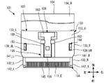
ここで、図2は、図1とは異なる方向から見た場合のプラグ101の斜視図である。図3は、プラグ101の分解斜視図である。図4~7は、それぞれ、プラグ101の正面図、平面図、右側面図、背面図である。なお、プラグ101の左側面図は、右側面図と同様に表される。
Here, FIG. 2 is a perspective view of the
第1配線板104は、信号を伝送するための可撓性を有する板状の部材であって、第1フレキシブル配線板に相当する。第1配線板104は、典型的には、マイクロスプリットライン構造又はストリップライン構造を有するFFC(Flexible Flat Cable)、FPC(Flexible Printed Circuit)などである。
The
ここで、マイクロスプリットライン構造或いはストリップライン構造とは、基準電位に接続される導体箔などのグランド導体が誘電体板の一方の主面に設けられるとともに、信号を伝送するための信号配線が当該誘電体板の他方の主面又は内部に設けられた構造である。このような構造は、一般的に高周波伝送に好適に採用される。 Here, the micro-split line structure or strip line structure means that a ground conductor such as a conductor foil connected to a reference potential is provided on one main surface of the dielectric plate, and signal wiring for transmitting signals is provided on the main surface of the dielectric plate. It is a structure provided on the other main surface or inside of the dielectric plate. Such a structure is generally suitable for high frequency transmission.
詳細には、第1配線板104は、第1誘電体板110と、複数の第1信号配線111と、第1グランド導体112とを有する。
Specifically, the
第1誘電体板110は、絶縁性と可撓性とを備えた薄い板状の部材であり、本実施の形態では前後方向に長い矩形の薄いフィルムである。第1誘電体板110の材料は、例えばポリイミドなどの樹脂である。第1誘電体板110の厚さ(上下方向の長さ)は、例えば、0.4mm(ミリメートル)程度である。
The first
詳細には、第1誘電体板110は、第1被保持部113と、一対の第1係止部114_L,114_Rと、第1延設部115とを有する。
Specifically, the first
第1被保持部113は、第1誘電体板110の前端から予め定められた長さL1までの部分である。第1被保持部113は、前端部(先端部)から予め定められた長さまでの部分が第1インシュレータ107の内部に保持される(図3,14参照)。
The first held
一対の第1係止部114_L,114_Rのそれぞれは、第1被保持部113の左端部と右端部とから内方(すなわち、左端部においては右方、右端部においては左方)へ向かう凹みを形成する部位である。本実施の形態では、一対の第1係止部114_L,114_Rの各々は、前端から予め定められた長さL2離れた位置に設けられており、奥行き(前後方向の長さ)が予め定められた長さLLの前後方向に細長い概ね矩形の凹みを形成する(図3,14参照)。 Each of the pair of first locking portions 114_L and 114_R is recessed inward from the left end and right end of the first held portion 113 (that is, rightward at the left end and leftward at the right end). It is the part that forms the In the present embodiment, each of the pair of first locking portions 114_L and 114_R is provided at a position separated from the front end by a predetermined length L2, and the depth (the length in the front-rear direction) is predetermined. A longitudinally elongated, generally rectangular recess of length LL is formed (see FIGS. 3 and 14).
これにより、一対の第1係止部114_L,114_Rの各々は、前端から長さL2の位置と、そこから長さLL離れた位置とで、左右方向に延びる平行な辺部と当該辺部の内方の端部を接続する前後方向に延びる辺部とを形成する。 As a result, each of the pair of first locking portions 114_L and 114_R has parallel side portions extending in the left-right direction at a position with a length L2 from the front end and at a position with a length LL away therefrom. and a longitudinally extending side connecting the inner ends.
第1延設部115は、第1被保持部113の後端に接続した前後方向に長い概ね矩形の部分である。第1延設部115は、段差を介して第1被保持部113の後端に接続しており、そのため、第1延設部115の幅は、第1被保持部113よりも広くなっている。幅は、側方への長さ、すなわち本実施の形態では左右方向の長さであって、後述する第1信号配線111の配列方向である。
The first
複数の第1信号配線111の各々は、信号を伝送するための配線であって、前後方向に延びる線状の導体から構成される。複数の第1信号配線111は、左右方向に予め定められた間隔を空けて、第1誘電体板110の内部に並べて設けられている。
Each of the plurality of
本実施の形態に係る複数の第1信号配線111の各々は、前端から予め定められた長さに対応する部分に第1配線露出部111_Eを有する。第1配線露出部111_Eは、第1誘電体板110が少なくとも上方に設けられていないことによって、第1信号配線111が少なくとも上方へ向けて外部に露出した部分である。
Each of the plurality of
第1グランド導体112は、基準電位に接続される導体であり、例えば金属箔である。第1グランド導体112は、第1誘電体板110の一方の主面である下面に概ね全体に広がるように設けられた金属層である。
The
なお、第1誘電体板110の他方の主面である上面、すなわち第1信号配線111を介して第1グランド導体112とは異なる方向には、基準電位に接続される金属箔などの導体が、第3グランド導体として、概ね全体に広がるようにさらに配置されてもよい。また例えば、複数の第1信号配線111は第1誘電体板110の内部ではなく、第1誘電体板110の上面に設けられてもよい。
A conductor such as a metal foil connected to a reference potential is provided on the upper surface, which is the other main surface of the first
第2配線板105は、信号を伝送するための可撓性を有する板状の部材であって、第2フレキシブル配線板に相当する。第2配線板105は、第1配線板104と概ね同様の構成を備えており、第1配線板104の下方に第1配線板104とは上下を逆転させた状態で、第1配線板104と概ね平行に配置されている。
The
すなわち、第2配線板105は、第1配線板104の第1誘電体板110、複数の第1信号配線111及び第1グランド導体112のそれぞれに相当する第2誘電体板116、複数の第2信号配線117及び第2グランド導体118を有する。
That is, the
第2誘電体板116は、第1誘電体板110と同様に、絶縁性と可撓性とを備えた薄い板状の部材であり、本実施の形態では前後方向に長い矩形の薄いフィルムである。詳細には、第2誘電体板116は、第1被保持部113と、一対の第1係止部114_L,114_Rと、第1延設部115とのそれぞれに相当する第2被保持部119と、一対の第2係止部120_L,120_Rと、第2延設部121とを有する。
Like the first
第2被保持部119は、第2誘電体板116の前端から予め定められた長さL1までの部分である。第2被保持部119は、前端部(先端部)から予め定められた長さまでの部分が第1インシュレータ107の内部に保持される(図3,14参照)。
The second held
一対の第2係止部120_L,120_Rのそれぞれは、第2被保持部119の左端部と右端部とから内部へ向かう凹みを形成する部位である。一対の第2係止部120_L,120_Rの各々は、前端から長さL2離れた位置に設けられており、奥行きが長さLLの前後方向に細長い概ね矩形の凹みを形成する(図3,14参照)。
Each of the pair of second locking portions 120_L and 120_R is a portion forming a recess extending inward from the left end portion and the right end portion of the second held
これにより、一対の第2係止部120_L,120_Rの各々は、一対の第1係止部114_L,114_Rの各々と同様に、前端から長さL2の位置と、そこから長さLL離れた位置とで、左右方向に延びる平行な辺部と前後方向に延びる辺部とを形成する。 As a result, each of the pair of second locking portions 120_L and 120_R, like each of the pair of first locking portions 114_L and 114_R, is positioned at a length L2 from the front end and at a position apart from the front end by a length LL. Thus, parallel side portions extending in the left-right direction and side portions extending in the front-rear direction are formed.
第2延設部121は、第2被保持部119の後端に接続した前後方向に長い概ね矩形の部分である。第2延設部121は、段差を介して第2被保持部119の後端に接続しており、そのため、第2延設部121の幅は、第1被保持部113よりも広くなっている。
The second extending
複数の第2信号配線117の各々は、複数の第1信号配線111の各々と同様に、信号を伝送するための配線であって、前後方向に延びる線状の導体から構成される。複数の第1信号配線111は、左右方向に予め定められた間隔を空けて、第2誘電体板116の内部に並べて設けられている。
Like each of the plurality of
本実施の形態に係る複数の第2信号配線117の各々は、前端から予め定められた長さに対応する部分に第2配線露出部117_Eを有する。第2配線露出部117_Eは、第2誘電体板116が少なくとも下方に設けられないことによって、第2信号配線117が少なくとも下方へ向けて外部に露出した部分である。
Each of the plurality of
第2グランド導体118は、第1グランド導体112と同様に、基準電位に接続される導体であり、例えば金属箔である。第2グランド導体118は、第2誘電体板116の一方の主面である上面に概ね全体に広がるように設けられた金属層である。すなわち、第1グランド導体112と第2グランド導体118とは、上下方向に向かい合うように配置される。
The
なお、第2誘電体板116の他方の主面である上面、すなわち第2信号配線117を介して第2グランド導体118とは異なる方向には、基準電位に接続される金属箔などの導体が、第4グランド導体として、概ね全体に広がるようにさらに配置されてもよい。また例えば、複数の第2信号配線117は第2誘電体板116の内部ではなく、第2誘電体板116の上面に設けられてもよい。
A conductor such as a metal foil connected to a reference potential is provided on the upper surface, which is the other main surface of the second
グランドプレート106は、基準電位に接続される板状の部材であって、第1配線板104と第2配線板105との間に配置される。グランドプレート106の材料は、金属などの導体である。
The
詳細には、グランドプレート106は、主板部122と、5対の弾性接点部123_L,123_Rと、一対の突起部124と、被保護部125とを有する。
Specifically, the
主板部122は、左右方向に長い概ね矩形の薄い板状の部位であって、その厚さは例えば0.2mm程度である。本実施の形態に係る主板部122は、5つの長孔部126と、一対の第3係止部127_L,127_Rとを有する。
The
長孔部126の各々は、上下方向に貫通した孔を形成する部位であって、上方から見て前後方向に長い矩形をなす。本実施の形態では、5つの長孔部126は、前後方向の概ね中央に左右対称に並んで設けられている。
Each of the
なお、長孔部126の数は、5つに限られず、1つ以上であればよい。また、複数の長孔部126が設けられる場合、複数の長孔部126は、適宜の配置で主板部122に設けられてよいが、第1配線板104及び第2配線板105のそれぞれを上方と下方とに全体的に押圧するために、左右対称に配置されることが望ましい。
Note that the number of
一対の第3係止部127_L,127_Rは、5つの長孔部126の左方と右方とに設けられ、上下方向に貫通した孔を形成する部位である。第3係止部127_L,127_Rの各々は、上方から見て前後方向に長い矩形をなす。
A pair of third locking portions 127_L and 127_R are provided on the left and right sides of the five
弾性接点部123_L,123_Rの各対は、互いに異なる長孔部126のいずれか1つに対応付けて設けられている。本実施の形態に係る弾性接点部123_L,123_Rの各々は、その弾性力によって押圧された状態で第1グランド導体112と第2グランド導体118との各々と接触する。
Each pair of elastic contact portions 123_L and 123_R is provided in association with one of the
詳細には、弾性接点部123_L,123_Rは、一方の端部が主板部122に固定された固定端であり他方の端部が自由端である2つの平行に延びる板バネ接点である。弾性接点部123_L,123_Rの各対は、第1接点128_L,128_Rと、第1弾性部129_L,129_Rとを有する。
Specifically, the elastic contact portions 123_L and 123_R are two leaf spring contacts extending in parallel, one end of which is a fixed end fixed to the
第1接点128_L,128_Rは、第1グランド導体112と第2グランド導体118とのそれぞれに接触する部位である。
The first contacts 128_L and 128_R are portions that come into contact with the
本実施の形態に係る第1接点128_Lは、弾性接点部123_Lの自由端から予め定められた長さまでの部分であって上方へ突き出す山状に形成されている。第1接点128_Lは、主に最上点近傍で第1グランド導体112に接触する。
The first contact 128_L according to the present embodiment is formed in the shape of a mountain extending upward from the free end of the elastic contact portion 123_L to a predetermined length. The first contact 128_L contacts the
また、第1接点128_Rは、弾性接点部123_Rの自由端から予め定められた長さまでの部分であって下方へ突き出す谷状に形成されている。第1接点128_Rは、主に最下点近傍で第2グランド導体118に接触する。
In addition, the first contact 128_R is formed in the shape of a valley projecting downward from the free end of the elastic contact portion 123_R to a predetermined length. The first contact 128_R contacts the
第1弾性部129_L,129_Rは、それぞれ、弾性を有することによって、第1グランド導体112及び第2グランド導体118へ向かう力を第1接点128_L,128_Rに加える部位である。本実施の形態に係る第1弾性部129_L,129_Rは、それぞれ、主板部122に接続して上前方又は下前方へ傾斜して延びて第1接点128_L,128_Rに接続する。
The first elastic portions 129_L and 129_R are portions that apply forces directed toward the
本実施の形態に係る第1弾性部129_L,129_Rは、それぞれ、基端部130_L,130_Rと板状部131_L,131_Rとを有する。 The first elastic portions 129_L and 129_R according to the present embodiment respectively have base end portions 130_L and 130_R and plate-like portions 131_L and 131_R.
基端部130_Lは、主板部122に接続して上前方へ向かって湾曲又は屈曲した部位である。基端部130_Rは、主板部122に接続して下前方へ向かって湾曲又は屈曲した部位である。
The base end portion 130_L is a portion that is connected to the
板状部131_Lは、基端部130_Lから上前方へ傾斜して延びて第1接点128_Lに接続する細長い板状の部位である。これにより、第1接点128_Lは、基端部130_Lよりも、グランドプレート106の前端部(先端部)の近くに位置することになる。
The plate-like portion 131_L is an elongated plate-like portion extending obliquely upward and forward from the base end portion 130_L and connected to the first contact point 128_L. As a result, the first contact 128_L is positioned closer to the front end (tip) of the
板状部131_Rは、基端部130_Rから下前方へ傾斜して延びて第1接点128_Rに接続する細長い板状の部位である。これにより、第1接点128_Rは、基端部130_Rよりも、グランドプレート106の先端部の近くに位置することになる。
The plate-like portion 131_R is an elongated plate-like portion extending obliquely downward and forward from the base end portion 130_R and connected to the first contact 128_R. This causes the first contact 128_R to be positioned closer to the distal end of the
一対の突起部124は、主板部122の左端部と右端部とのそれぞれから左方と右方とに突き出した小さい突起である。本実施の形態に係る一対の突起部124は、前後方向には長孔部126よりも後方に設けられている。
The pair of
なお、突起部124は、詳細後述するようにグランドプレート106が第1インシュレータ107に圧入されて押圧された状態に保持される構造であれば、1つであってもよく、設けられなくてもよい。
As long as the
被保護部125は、グランドプレート106の先端部から予め定められた長さまでの部分であって、後述する保護部134に収容される部分である。被保護部125は、左端部近傍と右端部近傍とに保護部134から外部に露出するプレート露出部132_L,132_Rを有する。
The protected
本実施の形態では、これまで説明をした構成を備えたグランドプレート106が一体的に構成される。なお、グランドプレート106は、複数の第1接点128_L,128_Rと第1弾性部129_L,129_Rと主板部122との一部又は全部が、別部材で構成されて半田付けなどにより導通可能に接続されていてもよい。
In this embodiment, the
第1インシュレータ107は、第1配線板104と第2配線板105とグランドプレート106とを保持する部材である。本実施の形態に係る第1インシュレータ107は、外観図である図8~10と断面図である図11及び12とに示すように、本体部133と、保護部134と、ロック機構取付部135とを有する。第1インシュレータ107は、例えば、樹脂を材料として一体的に形成される。なお、図8~10は、それぞれ、第1インシュレータ107の正面図、平面図、背面図である。また、図11と図12は、それぞれ、図8のXI-XI線とXII-XII線とにおける第1インシュレータ107の断面図である。
本体部133と保護部134とは、第1配線板104、第2配線板105及びグランドプレート106が収容される収容空間136を内部に形成する部位である。本体部133と保護部134とは、第1配線板104、第2配線板105及びグランドプレート106の全体の前端部(先端部)、左右の両側端部、外方を向く2つの主面部104_U,105_Dという5つの部位それぞれの少なくとも一部を覆うようにして収容空間136を形成している。
The
詳細後述するように、本実施の形態において、第1配線板104、第2配線板105及びグランドプレート106の全体の前端部は、第1配線板104、第2配線板105及びグランドプレート106の各々の前端部である。
As will be described later in detail, in the present embodiment, the front end portions of the entire
第1配線板104、第2配線板105及びグランドプレート106の全体の左右の両側端部は、第1配線板104、第2配線板105及びグランドプレート106の各々の左端部と右端部とである。
The left and right side edges of the
第1配線板104、第2配線板105及びグランドプレート106の全体の外方を向く2つの主面部は、第1配線板104の上面部104_Uと第2配線板105の下面部105_Dとである。
The two main surfaces of the
本体部133は、図8~10に示すように、概ね直方体の外形をなす部位であって、各々が概ね平板状の上壁部133_Uと下壁部133_Dと左壁部133_Lと右壁部133_Rとから構成される。これにより、本体部133の内部には、概ね直方体の収容空間136の一部が形成される。
As shown in FIGS. 8 to 10, the
本体部133が形成する収容空間136には、グランドプレート106と、その上下のそれぞれに配置された第1配線板104及び第2配線板105とが収容される。言い換えると、本体部133は、グランドプレート106、第1配線板104及び第2配線板105の各々の左右の両側端部の一部と、第1配線板104の上面部104_Uの一部と、第2配線板105の下面部105_Dの一部とを覆う。
The
第1配線板104は、その上面部104_Uが上壁部133_Uの内面(下面)と互いに接触するように配置されている。第2配線板105は、その下面部105_Dが下壁部133_Dの内面(上面)と互いに接触するように配置されている。これにより、第1グランド導体112と第2グランド導体118との各々は、グランドプレート106に上下方向に対向して配置される。
そして、上述の通り、グランドプレート106の第1接点128_L,128_Rのそれぞれは、第1グランド導体112と第2グランド導体118とに接触する。このとき、グランドプレート106の第1接点128_L,128_Rのそれぞれは、第1弾性部129_L,129_Rの弾性力によって第1グランド導体112と第2グランド導体118とに向かう力を受けている。
Then, as described above, the first contacts 128_L and 128_R of the
これにより、グランドプレート106が第1グランド導体112と第2グランド導体118とのそれぞれと電気的に確実に接触して導通する。また、第1配線板104と第2配線板105とのそれぞれが上壁部133_Uと下壁部133_Dとに押圧された状態で、本体部133の内部に保持される。
As a result, the
詳細には、本体部133には、テーパ部138と、カバー取付部139_UL,139_UR,139_Dと、プレートガイド溝部140_L,140_Rと、傾斜部141_L,141_R,141_Dとが設けられている。
Specifically, the
テーパ部138は、後端部から前方に向かって収容空間136を次第に縮小させる部位である。テーパ部138は、それぞれ、上壁部133_U、下壁部133_D、左壁部133_L、右壁部133_Rの内面の後端近傍に設けられている。
The tapered
カバー取付部139_UL,139_UR,139_Dは、詳細後述するカバー108を取り付けるための部位であって、上壁部133_Uと下壁部133_Dとに設けられる。カバー取付部139_UL,139_UR,139_Dの各々は、抜け止め嵌合部に相当する。
The cover mounting portions 139_UL, 139_UR, and 139_D are portions for mounting the
より詳細には、カバー取付部139_UL,139_URの各々は、上下方向に貫通する貫通孔を上壁部133_Uに形成しており、上方から見て概ね前後方向に細長い矩形をなす。カバー取付部139_ULは、上壁部133_Uの左端近傍に設けられている。カバー取付部139_URは、上壁部133_Uの右端近傍に設けられている。カバー取付部139_Dは、上下方向に貫通する貫通孔を下壁部133_Dに形成しており、上方から見て概ね、下壁部133_Dの左端近傍と右端近傍との間に延在する左右方向に長い矩形をなす。 More specifically, each of the cover attachment portions 139_UL and 139_UR has a through-hole extending vertically through the upper wall portion 133_U, and has a substantially elongated rectangular shape in the front-rear direction when viewed from above. The cover attachment portion 139_UL is provided near the left end of the upper wall portion 133_U. The cover attachment portion 139_UR is provided near the right end of the upper wall portion 133_U. The cover attachment portion 139_D has a through-hole extending vertically through the lower wall portion 133_D. form a long rectangle.
本実施の形態では、カバー取付部139_UL,139_UR,139_Dは、前後方向には、上壁部133_U及び下壁部133_Dの中央よりやや前方の概ね同じ位置に、概ね同じ長さで設けられる。また、カバー取付部139_Dの左端部と右端部とは、それぞれの左右方向の位置がカバー取付部139_ULの左端部とカバー取付部139_URの右端部と概ね同じである。 In the present embodiment, the cover attachment portions 139_UL, 139_UR, and 139_D are provided in the front-rear direction at substantially the same position slightly forward of the center of the upper wall portion 133_U and the lower wall portion 133_D and with substantially the same length. The left end and right end of the cover mounting portion 139_D are substantially the same as the left end of the cover mounting portion 139_UL and the right end of the cover mounting portion 139_UR in the horizontal direction.
プレートガイド溝部140_L,140_Rは、グランドプレート106を保持する部位であって、左壁部133_Lと右壁部133_Rとのそれぞれの内面で前後方向に延びる細長い溝を形成する。プレートガイド溝部140_L,140_Rのそれぞれは、左右方向に対向するように上下方向の位置を揃えて設けられており、グランドプレート106の左端部と右端部とが嵌め込まれる。これによって、グランドプレート106は、第1インシュレータ107に保持される。
The plate guide groove portions 140_L and 140_R are portions that hold the
より詳細には、プレートガイド溝部140_L,140_Rの各々の上下方向の間隔は、グランドプレート106を配置できる長さであって、グランドプレート106の厚さよりも僅かに大きい。プレートガイド溝部140_L,140_Rの各々の後端近傍は、第1インシュレータ107へのグランドプレート106の取り付けを容易にするため、外方へ向けて拡大している。
More specifically, the vertical interval between the plate guide grooves 140_L and 140_R is a length that allows the
また、プレートガイド溝部140_L,140_Rの左端部と右端部とは、一対の突起部124が擦れながら移動できる間隔で設けられる。これにより、第1インシュレータ107は、一対の突起部124を左右から直接的に押圧した状態でグランドプレート106を保持する。
In addition, the left end and right end of the plate guide grooves 140_L and 140_R are provided at intervals that allow the pair of
傾斜部141_L,141_R,141_Dは、左壁部133_L、右壁部133_R、下壁部133_Dの外面のそれぞれの前端近傍にて、幅が小さくなるように或いは厚さが薄くなるように傾斜した部位である。 The inclined portions 141_L, 141_R, and 141_D are portions inclined so as to reduce the width or thickness near the front ends of the outer surfaces of the left wall portion 133_L, the right wall portion 133_R, and the lower wall portion 133_D. is.
保護部134は、概ね、本体部133の前方に突き出して設けられており、レセプタクル102に嵌め合わされる部分である。保護部134の内部には、本体部133が形成する収容空間136の一部と互いに連続する収容空間136の残部が形成される。
The
保護部134が形成する収容空間136には、第1配線板104と第2配線板105とグランドプレート106との各々の先端部近傍が収容される。ここで、先端部近傍とは、先端部を含む部分であって、先端部から予め定められた長さまでの部分である。グランドプレート106の先端部近傍は、被保護部125である。保護部134は本体部133よりも幅が狭くなっており、これによって、被保護部125の左端部及び右端部が保護部134の外部に露出する。
詳細には、保護部134は、左右の側壁部142_L,142_Rと、第1仕切部143と、第2仕切部144と、先端保護部145とを有する。
Specifically, the
側壁部142_L,142_Rの各々は、本体部133の前方に設けられており、保護部134の側端部を構成する概ね直方体の部位である。側壁部142_L,142_Rの各々は、上下方向の概ね中央に、プレートガイド溝部140_L,140_Rから連続的に前方へ延びるスリット部146が設けられている。スリット部146により形成される空間が、後述するプレート保持溝147の一部となっている。
Each of the side wall portions 142_L and 142_R is provided in front of the
また、側壁部142_L,142_Rの各々の前端近傍は、レセプタクル102への嵌め合わせを容易にするため、前方へ向かって縮小している。
Also, the vicinity of the front end of each of the side walls 142_L and 142_R is reduced forward in order to facilitate fitting into the
第1仕切部143と第2仕切部144とは、それぞれ、前後左右に拡がる概ね矩形の平板状の部位であって、各々の左右の端部が側壁部142_L,142_Rのそれぞれに接続している。第1仕切部143と第2仕切部144とは、各々の厚さが例えば0.4mm程度の薄さである。
The
第1仕切部143と第2仕切部144とは、グランドプレート106の厚さよりも上下方向の長さが僅かに長いすき間を空けて上下に並べて設けられる。このすき間は、上述のスリット部146が形成する空間とともに、プレート保持溝147を形成する。
The
プレート保持溝147は、グランドプレート106の被保護部125が配置される収容空間136であり、その後端近傍は、第1インシュレータ107へのグランドプレート106の取り付けを容易にするため、上下方向の長さが後方へ向かって長くなっている。
The
ここで、側壁部142_L,142_Rの幅は、プレート露出部132_L,132_Rを露出させる程度に、本体部133の幅よりも狭い。
Here, the width of the side wall portions 142_L and 142_R is narrower than the width of the
本実施の形態では、側壁部142_L,142_Rの幅は、側壁部142_L,142_Rの各々の外面(側壁部142_Lの左側面と側壁部142_Rの右側面)の左右方向の長さである。そして、側壁部142_L,142_Rの幅は、本体部133の左壁部133_Lと右壁部133_Rとの内面間の左右方向の長さと概ね同じである。これにより、グランドプレート106は、プレートガイド溝部140_L,140_Rよりも前方に配置された部分が、プレート露出部132_L,132_Rとして保護部134の外部に露出する。
In the present embodiment, the widths of the side wall portions 142_L and 142_R are the lengths in the horizontal direction of the respective outer surfaces of the side wall portions 142_L and 142_R (the left side surface of the side wall portion 142_L and the right side surface of the side wall portion 142_R). The widths of the side wall portions 142_L and 142_R are approximately the same as the length in the horizontal direction between the inner surfaces of the left wall portion 133_L and the right wall portion 133_R of the
また、第1仕切部143は、第1突出部143_Aと、第1収容部143_Bとを有する。第1突出部143_Aは、本体部133の前端部よりも前方に突き出した部位である。第1収容部143_Bは、本体部133の前端部よりも後方に突き出して本体部133の内部に配置される部位である。
In addition, the
これによって、第1収容部143_Bと上壁部133_Uとは、第1挿設孔148を形成する。第1挿設孔148は、第1配線板104が前後方向に貫通して配置される収容空間136である。第1挿設孔148の後端近傍は、第1インシュレータ107への第1配線板104の取り付けを容易にするため、上下方向の長さが後方へ向かって長くなっている。
Accordingly, the first receiving portion 143_B and the upper wall portion 133_U form a
また、第1突出部143_Aは、その上方に第1配線板104の先端部近傍が収容される収容空間136を形成する。第1突出部143_Aには、その上面に第1配線板104の下面(すなわち、本実施の形態では第1グランド導体112)が接触するように第1配線板104の先端部近傍が配置される。
Further, first projecting portion 143_A forms
第2仕切部144は、第1仕切部143と同様に、第2突出部144_Aと、第2収容部144_Bとを有する。第2突出部144_Aは、本体部133の前端部よりも前方に突き出した部位である。第2収容部144_Bは、本体部133の前端部よりも後方に突き出して本体部133の内部に配置される部位である。
The
これによって、第2収容部144_Bと下壁部133_Dとは、第2挿設孔149を形成する。第2挿設孔149は、第2配線板105が前後方向に貫通して配置される収容空間136である。第2挿設孔149の後端近傍は、第1インシュレータ107への第2配線板105の取り付けを容易にするため、上下方向の長さが後方へ向かって長くなっている。
Accordingly, the second receiving portion 144_B and the lower wall portion 133_D form a
また、第2突出部144_Aには、その下方に第2配線板105の先端部近傍が収容される収容空間136を形成する。そして、第2突出部144_Aには、その下面に第2配線板105の上面(すなわち、本実施の形態では第2グランド導体118)が接触するように第2配線板105の先端部近傍が配置される。
In addition, an
先端保護部145は、左右方向に細長い概ね矩形の平板状をなす部分であり、その後面が第1突出部143_Aと第2突出部144_Aとの前端にて左右方向の概ね全幅にわたって連続的に接続している。これにより、先端保護部145は、第1突出部143_Aと第2突出部144_Aとの先端近傍を補強する。
The front
このように補強することで、比較的薄い部位である第1突出部143_Aと第2突出部144_Aとが例えば湾曲することや互いに離間することなどによってプラグ101が損傷する可能性を低減することができる。
Reinforcement in this way can reduce the possibility of damage to the
先端保護部145の上端部は、側方から見て、第1突出部143_Aに配置された第1配線板104の前端の少なくとも一部を覆うように上方へ延びている。そして、先端保護部145の前面上方は、前方から後方へ向かって次第に上下方向の長さが長くなるように、上前方に突き出して湾曲している。
The upper end of
先端保護部145の下端部は、側方から見て、第2突出部144_Aに配置された第2配線板105の前端の少なくとも一部を覆うように下方へ延びている。そして、先端保護部145の前面下方は、前方から後方へ向かって次第に上下方向の長さが長くなるように、下前方に突き出して湾曲している。
A lower end portion of
先端保護部145は、側壁部142_L,142_Rと本体部133の上壁部133_U及び下壁部133_Dとともに、第1開口150と第2開口151とを形成する。
The
第1開口150は、第1突出部143_Aにより形成される収容空間136を上方に向かって外部に接続する開口である。本実施の形態に係る第1開口150は、先端保護部145の上端部と、側壁部142_L,142_Rと、上壁部133_Uとにより形成される。
The
上述の通り、第1配線板104の先端部近傍は、第1グランド導体112が接触するように第1突出部143_Aに配置される。また、上述の第1配線露出部111_Eが、第1配線板104の先端部近傍に設けられている。そのため、第1配線露出部111_E、言い換えると、第1信号配線111の各々の一部が第1開口150を通じて、第1インシュレータ107の外部に露出する。
As described above, the vicinity of the tip portion of the
第2開口151は、第2突出部144_Aにより形成される収容空間136を下方に向かって外部に接続する開口である。本実施の形態に係る第2開口151は、先端保護部145の下端部と、側壁部142_L,142_Rと、下壁部133_Dとにより形成される。
The
上述の通り、第2配線板105の先端部近傍は、第2グランド導体118が接触するように第2突出部144_Aに配置される。また、上述の第2配線露出部117_Eが、第2配線板105の先端部近傍に設けられている。そのため、第2配線露出部117_E、言い換えると、第2信号配線117の各々の一部が第2開口151を通じて、第1インシュレータ107の外部に露出する。
As described above, the vicinity of the tip of the
ロック機構取付部135は、詳細後述する第1ロック機構部109を取り付けるための部位であって、本実施の形態では上壁部133_Uの前方中央に設けられる。
The lock
本実施の形態に係るロック機構取付部135は、上壁部133_Uの上面から上方へ突き出して前後方向に延びた一対の突状部153を有する。一対の突状部153は、上壁部133_Uの前端部近傍に設けられており、左右方向の概ね中央を介して互いに対向するように設けられている。突状部153の各々は、他方の突条部153と対向する面の下端部に、前後方向に延びる概ね直方体の細長い切欠きが設けられている。これによって、一対の突状部153は、上壁部133_Uの上面とともにスライド溝部154を形成する。
The lock
カバー108は、カバー取付部139_UL,139_UR,139_Dに取り付けられる部材であって、例えば、樹脂を材料として一体的に形成されている。カバー108は、抜け止め部材に相当する。カバー108は、カバー取付部139_Dに嵌め合わされる蓋部155と、カバー取付部139_UL,139_URに嵌め合わされる抜け止め部156_L,156_Rとを有する。
The
蓋部155は、左右方向に長い概ね直方体の部位である。蓋部155は、例えばカバー取付部139_Dに締まり嵌めで嵌め合わされることによって、カバー取付部139_Dが形成する貫通孔を塞いで固定される。
The
抜け止め部156_L,156_Rは、それぞれ、蓋部155の左端部と右端部とから上方へ延びる概ね直方体の部位である。抜け止め部156_L,156_Rは、それぞれ、例えばカバー取付部139_UL,139_URに締まり嵌めで嵌め合わされることによって、カバー取付部139_UL,139_URが形成する貫通孔を塞いで固定される。
The retaining portions 156_L and 156_R are approximately rectangular parallelepiped portions extending upward from the left end and right end of the
ここで、第1配線板104、第2配線板105及びグランドプレート106が第1インシュレータ107に保持された場合に、カバー取付部139_D、第1係止部114_L、第2係止部120_L、第3係止部127_L、カバー取付部139_ULが、上下方向に並ぶ。これとともに、カバー取付部139_D、第1係止部114_R、第2係止部120_R、第3係止部127_R、カバー取付部139_URが、上下方向に並ぶ。
Here, when
そのため、カバー取付部139_D、第1係止部114_L、第2係止部120_L、第3係止部127_L、カバー取付部139_ULが上下方向に連続する概ね直方体の空間を形成し、この空間を蓋部155及び抜け止め部156_Lが貫通する。
Therefore, the cover mounting portion 139_D, the first locking portion 114_L, the second locking portion 120_L, the third locking portion 127_L, and the cover mounting portion 139_UL form a generally rectangular parallelepiped space that is continuous in the vertical direction, and this space is covered by a lid. The
同様に、カバー取付部139_D、第1係止部114_R、第2係止部120_R、第3係止部127_R、カバー取付部139_URが上下方向に連続する概ね直方体の空間を形成し、この空間を蓋部155及び抜け止め部156_Rが貫通する。
Similarly, the cover mounting portion 139_D, the first locking portion 114_R, the second locking portion 120_R, the third locking portion 127_R, and the cover mounting portion 139_UR form a generally rectangular parallelepiped space that continues in the vertical direction. The
これにより、抜け止め部156_L,156_Rは、第1配線板104及び第2配線板105の前後左右の位置がズレないように第1係止部114_L,114_R及び第2係止部120_L,120_Rに係わり合う。グランドプレート106は、上述の通り、プレート保持溝147によって第1インシュレータ107に中に位置ズレしないように保持されるので、第3係止部127_L,127_Rとは僅かなすき間を空けて貫通するように係わり合うとよい。
As a result, the retaining portions 156_L and 156_R are attached to the first locking portions 114_L and 114_R and the second locking portions 120_L and 120_R so that the positions of the
このように、抜け止め部156_L,156_Rが第1係止部114_L,114_R、第2係止部120_L,120_R及び第3係止部127_L,127_Rと係わり合う。これによって、第1配線板104、第2配線板105及びグランドプレート106の前後方向の移動が予め定められた範囲に抑止される。その結果、第1配線板104、第2配線板105及びグランドプレート106が第1インシュレータ107から抜け出すことを防止することが可能となる。
In this way, the retaining portions 156_L and 156_R engage with the first locking portions 114_L and 114_R, the second locking portions 120_L and 120_R, and the third locking portions 127_L and 127_R. As a result, the movement of the
第1ロック機構部109は、プラグ101がレセプタクル102に嵌め合わされた場合に、プラグ101をレセプタクル102から取り外せないロック状態と、取り外し可能な解除状態とを切り替えるための部位である。本実施の形態に係る第1ロック機構部109は、第1インシュレータ107とは別の部材として構成され、例えば金属を材料として一体的に形成される。
The
詳細には、第1ロック機構部109は、平板部157と、湾曲部158と、ロック部159と、操作部160とを有する。
Specifically, the first
平板部157は、概ね矩形の平板をなす部位であって、ロック機構取付部135のスライド溝部154に嵌め込まれる。平板部157は、例えば締まり嵌めによって、ロック機構取付部135に押圧された状態で保持される。
The
湾曲部158は、平板部157の前端から上方へ湾曲して後方へ向かうように折り返す部位である。ロック部159は、湾曲部158に接続して後方へ延びるとともに上方へ突き出す部分を含む部位である。操作部160は、ロック部159からさらに方向へ延びる部位である。
The
このような第1ロック機構部109によれば、力を受けていない状態では、ロック部159が予め定められたロック位置に位置する。そして、操作者が操作部160を下方へ押し下げるなど、第1ロック機構部109が主に湾曲部158による弾性力に抗してロック部159を下方へ移動させる力を受けることによって、ロック部159が下方の解除位置に移動する。
According to such a first
(レセプタクル102の構成)
レセプタクル102は、プラグ101と嵌まり合うコネクタである。レセプタクル102は、斜視図である図1、正面図である図13に示すように、第2インシュレータ161と、複数の第1コンタクト162と、複数の第2コンタクト163と、金属シェル164とを備える。
(Configuration of receptacle 102)
第2インシュレータ161は、プラグ101が嵌め込まれる部材である。第2インシュレータ161は、例えば、樹脂を材料として一体的に形成される。
The
本実施の形態に係る第2インシュレータ161は、概ね直方体をなし、内部には前方に開放した概ね直方体の嵌合空間Sを有する。この嵌合空間Sに、プラグ101の保護部134とこれに収容された第1配線板104、第2配線板105及びグランドプレート106が嵌め込まれる。
The
本実施の形態に係る第2インシュレータ161は、左右の側壁部に側壁開口部165_L,165_Rを有する。側壁開口部165_L,165_Rの各々は、第2インシュレータ161の外部とその内部の嵌合空間Sとを接続し、前方に開放した開口を形成する部位である。すなわち、側壁開口部165_L,165_Rの各々は、プラグ101が嵌め合わされた場合に、グランドプレート106と金属シェル164との間の空間を形成する部位である。
複数の第1コンタクト162は、第2インシュレータ161の内面上部に左右方向に並べて保持された概ね線状の導体である。複数の第1コンタクト162は、最下点の近傍を接点とし、弾性によって当該接点に下方へ向かう力を加えることができるバネ接点である。プラグ101と嵌め合わされた場合に、複数の第1コンタクト162は、それぞれの接点で第1配線露出部111_Eに接触する。
The plurality of
複数の第2コンタクト163は、第2インシュレータ161の内面下部に左右方向に並べて保持された概ね線状の導体である。複数の第2コンタクト163は、最上点の近傍を接点とし、弾性によって当該接点に上方へ向かう力を加えることができるバネ接点である。プラグ101と嵌め合わされた場合に、複数の第2コンタクト163は、それぞれの接点で第2配線露出部117_Eに接触する。
The plurality of
金属シェル164は、第2インシュレータ161の周囲に配置される金属製の部材である。金属シェル164は、シェル上面部166と、左右のシェル側面部167_L,167_Rとを有する。
シェル上面部166は、第2インシュレータ161の上方に配置される概ね矩形平板状の部位であって、第2ロック機構部168を有する。
The shell
第2ロック機構部168は、シェル上面部166の後方中央にて上方へ突き出す台形状をなす部位である。第2ロック機構部168と第2インシュレータ161との間には、プラグ101が嵌め合わされた場合に、ロック機構取付部135及びこれに取り付けられた第1ロック機構部109が嵌め込まれる空間が形成されている。
The second
また、第2ロック機構部168は、その上部にロック穴部169を有する。ロック穴部169は、概ね矩形の上下方向に貫通した穴を第2ロック機構部168の上部平板状の部位に形成する。本実施の形態に係るロック穴部169は、第2ロック機構部168の上部において左右方向には概ね中央であって後端から予め定められた長さ離れた位置に穴を形成する。
Also, the second
左右のシェル側面部167_L,167_Rは、それぞれ、シェル上面部166の左端部と右端部とから屈曲して下方へ延びる概ね矩形平板状の部位であって、第2インシュレータ161の左方と右方とに配置される。
The left and right shell side portions 167_L and 167_R are substantially rectangular plate-like portions that bend and extend downward from the left end and right end of the shell
左右のシェル側面部167_L,167_Rの各々は、左右の側面開口部170_L,170_Rと、左右のグランド金具171_L,171_Rと、左右のグランド接続部172_L,172_Rとを有する。 Left and right shell side portions 167_L and 167_R each have left and right side openings 170_L and 170_R, left and right ground metal fittings 171_L and 171_R, and left and right ground connection portions 172_L and 172_R.
側面開口部170_L,170_Rは、それぞれ、シェル側面部167_L,167_Rに左右方向に貫通する前後方向に細長い概ね矩形の開口を形成する。 The side openings 170_L and 170_R respectively form generally rectangular openings elongated in the front-rear direction that pass through the shell side portions 167_L and 167_R in the left-right direction.
左右のグランド金具171_L,171_Rの各々は、プラグ101が嵌め合わされた場合に、グランドプレート106の側端部のうち第1インシュレータ107の外部に露出した部分に接触する部位である。左右のグランド金具171_L,171_Rは、左右方向に対向するように対をなして設けられている。プラグ101が嵌め合わされた場合に、左右のグランド金具171_L,171_Rは、グランドプレート106の側端部のうち第1インシュレータ107の外部に露出した部分のそれぞれの側方に位置付けられる。
Each of the left and right ground metal fittings 171_L and 171_R is a part that comes into contact with the part of the side end of the
本実施の形態に係るグランド金具171_L,171_Rは、それぞれ、側面開口部170_L,170_Rに一端が固定された前後方向に延びる板バネ接点から構成される。 The ground metal fittings 171_L and 171_R according to the present embodiment are configured by plate spring contacts extending in the front-rear direction and having one ends fixed to the side openings 170_L and 170_R, respectively.
詳細には、グランド金具171_L,171_Rの各々は、第2接点173_L,173_Rと、第2弾性部174_L,174_Rとを有する。グランド金具171_L,171_Rは、それぞれ、第2接点173_L,173_Rが嵌合空間Sに位置付けられるように、側面開口部170_L,170_Rを左右方向に通過して配置される。 Specifically, each of the ground metal fittings 171_L and 171_R has second contacts 173_L and 173_R and second elastic portions 174_L and 174_R. The ground metal fittings 171_L and 171_R are arranged to pass through the side openings 170_L and 170_R in the horizontal direction so that the second contacts 173_L and 173_R are positioned in the fitting space S, respectively.
第2接点173_L,173_Rの各々は、グランドプレート106の側端部のうち第1インシュレータ107の外部に露出した部分に接触する部位である。
Each of the second contacts 173_L and 173_R is a part that contacts a portion of the side end of the
本実施の形態に係る第2接点173_Lは、グランド金具171_Lの他端である自由端から予め定められた長さのまでの部分であって右方へ突き出すように湾曲している。第2接点173_Lは、主に最右点近傍で、第1インシュレータ107の外部に露出したグランドプレート106の左端部に接触する。
The second contact 173_L according to the present embodiment is a portion extending from the free end, which is the other end of the ground metal fitting 171_L, to a predetermined length and is curved so as to protrude rightward. The second contact 173_L contacts the left end of the
第2接点173_Rは、グランド金具171_Rの他端である自由端から予め定められた長さのまでの部分であって左方へ突き出すように湾曲している。第2接点173_Rは、主に最左点近傍で、第1インシュレータ107の外部に露出したグランドプレート106の右端部に接触する。
The second contact 173_R is a portion from the free end, which is the other end of the ground metal fitting 171_R, to a predetermined length and is curved so as to protrude leftward. Second contact 173_R contacts the right end of
第2弾性部174_L,174_Rは、それぞれ、弾性を有することによって、右方及び左方へ向かう力を第2接点173_L,173_Rに加える部位である。本実施の形態に係る第2弾性部174_L,174_Rは、それぞれ、側面開口部170_L,170_Rに接続して方向へ延びて第2接点173_L,173_Rに接続する細長い部位である。 The second elastic portions 174_L and 174_R are portions that apply rightward and leftward forces to the second contacts 173_L and 173_R, respectively, by having elasticity. The second elastic portions 174_L and 174_R according to the present embodiment are elongated portions that connect to the side openings 170_L and 170_R and extend in the direction to connect to the second contacts 173_L and 173_R, respectively.
このようなグランド金具171_L,171_Rが、上述の通り、左右方向に対向するように対をなして設けられる。そのため、プラグ101が嵌め合わされた場合に、グランド金具171_L,171_Rは、グランドプレート106を側方から挟んでグランドプレート106に接触する。
Such ground fittings 171_L and 171_R are provided in pairs so as to face each other in the left-right direction, as described above. Therefore, when the
左右のグランド接続部172_L,172_Rは、それぞれ、左右のシェル側面部167_L,167_Rの下端から下方へ突き出す小突起である。本実施の形態に係る左右のグランド接続部172_L,172_Rは、左右のシェル側面部167_L,167_Rの各々に2つずつ設けられているが、1つ或いは3つ以上であってもよい。グランド接続部172_L,172_Rの各々は、対象物のグランド配線に半田付けなどで固定される。 The left and right ground connection portions 172_L and 172_R are small protrusions protruding downward from the lower ends of the left and right shell side portions 167_L and 167_R, respectively. Two left and right ground connection portions 172_L and 172_R according to the present embodiment are provided on each of the left and right shell side portions 167_L and 167_R, but may be one or three or more. Each of the ground connection portions 172_L and 172_R is fixed to the ground wiring of the object by soldering or the like.
これまで、本実施の形態に係るコネクタ組立体100とこれを構成するプラグ101及びレセプタクル102との構成について説明した。ここから、プラグ101及びレセプタクル102の製造方法の例について説明する。
So far, the configurations of the
(プラグ101の製造方法)
プラグ101を製造するために、第1配線板104と、第2配線板105と、グランドプレート106と、第1インシュレータ107と、カバー108と、第1ロック機構部109との各々が準備される。
(Manufacturing method of plug 101)
In order to manufacture
ここで、第1配線板104の準備では、例えば、複数の第1信号配線111を薄い樹脂製のフィルムで上下から挟み、これらのフィルムを接着、溶着などにより相互に固定される。これの一方の主面に金属箔を張り付けることなどにより第1グランド導体112が設けられる。そして、前端近傍のフィルムの一部を取り除くことで、第1配線露出部111_Eが形成される。これにより、第1配線板104を容易に製造して準備することができる。第2配線板105も、第1配線板104と同様の方法で製造して準備することができる。
Here, in preparing the
グランドプレート106は、例えば、予め定められた形状に切り出された金属板に、長孔部126の各々に一対の細長い概ね矩形の小片を接続した状態の孔と、一対の第3係止部127_L,127_Rとが空けられる。そして、長孔部126の各々に接続した各小片が、弾性接点部123_L,123_Rに応じた形状に折り曲げられる。これにより、一端が長孔部126に固定された弾性接点部123_L,123_Rを含むグランドプレート106を容易に製造して準備することができる。
The
第1インシュレータ107とカバー108との各々は、例えば、樹脂成形により製造されて準備されるとよい。
Each of
第1ロック機構部109は、例えば、予め定められた形状に切り出された金属板を適宜の方法で曲げることによって製造されて準備されるとよい。
The first
グランドプレート106が、第1インシュレータ107の後方からプレートガイド溝部140_L,140_Rに沿って挿入される。このとき、プレートガイド溝部140_L,140_Rに一対の突起部124が接触するので、グランドプレート106は、第1インシュレータ107から力を受けた状態で挿入される。このように、予め定められた長さが圧入されると、グランドプレート106は、押圧された状態で第1インシュレータ107に保持される。
The
続けて、第1配線板104と第2配線板105とが、第1インシュレータ107の後方からグランドプレート106の上下のそれぞれに挿入される。第1配線板104と第2配線板105は、各先端が先端保護部145に接触するまで押し込まれる。このとき、第1配線板104と第2配線板105とは、それぞれ、弾性接点部123_L,123_Rによって上壁部133_Uと下壁部133_Dと向けて押圧された状態で保持される。
Subsequently, the
カバー108が、第1インシュレータ107の下方からカバー取付部139_UL,139_UR,139_Dに圧入されることで嵌め込まれる。これにより、抜け止め部156_L,156_Rが第1インシュレータ107の内部を上下方向に貫くことによって、第1配線板104、第2配線板105及びグランドプレート106が第1インシュレータ107から抜け出すことが防止される。したがって、第1配線板104、第2配線板105及びグランドプレート106が第1インシュレータ107から抜け出にし難いプラグ101を容易に製造することが可能になる。
The
続けて、第1ロック機構部109が、平板部157をスライド溝部154に前方から圧入される。これによって、第1ロック機構部109は、押圧された状態でロック機構取付部135に保持され、本実施の形態に係るプラグ101が完成する。
Subsequently, the first
このように、本実施の形態によれば、プラグ101を容易に組み立てて製造することが可能になる。 Thus, according to the present embodiment, plug 101 can be easily assembled and manufactured.
(レセプタクル102の製造方法)
レセプタクル102を製造するために、第2インシュレータ161と、複数の第1コンタクト162と、複数の第2コンタクト163と、金属シェル164との各々が準備される。
(Manufacturing method of receptacle 102)
In order to manufacture
ここで、第2インシュレータ161は、例えば、樹脂成形により製造されて準備されるとよい。第1コンタクト162の各々と第2コンタクト163の各々とは、概ね線状の細長い金属棒を予め定められた形状に曲げることで製造されて準備されるとよい。
Here, the
金属シェル164を製造するために、予め定められた形状の金属平板が準備される。この金属平板には、第2ロック機構部168を形成するための前端中央から予め定められた長さ後方に離れた位置に、左右方向の切り込みが設けられる。そして、当該切れ込みの前方の予め定められた位置にロック穴部169が設けて、切れ込みより前方の部分を上方へ湾曲させることで、第2ロック機構部168が形成される。
To manufacture the
さらに、金属平板には、左端部から予め定められた長さ右方向に離れた位置と右端部から予め定められた長さ左方向に離れた位置とに、側面開口部170_L,170_Rに前方に延びる細長い矩形片を接続した状態の孔が設けられる。側面開口部170_L,170_Rのそれぞれに接続した矩形辺が、弾性接点部123_L,123_Rに応じた形状に折り曲げられる。これにより、一端が側面開口部170_L,170_Rのそれぞれに固定された弾性接点部123_L,123_Rが形成される。 Further, the flat metal plate has a predetermined length left from the left end and a predetermined length left from the right end. Apertures are provided with connecting elongated rectangular strips. Rectangular sides connected to the side openings 170_L and 170_R are bent into shapes corresponding to the elastic contact portions 123_L and 123_R. Thereby, elastic contact portions 123_L and 123_R are formed, one ends of which are fixed to the side openings 170_L and 170_R, respectively.
そして、左端部と右端部とのそれぞれから予め定めた長さ、離れた位置で前後方向に延びる線で概ね直角に曲げることで、左右のシェル側面部167_L,167_Rに相当する部分が形成される。これにより、シェル側面部167_L,167_Rの側面開口部170_L,170_Rのそれぞれに固定された弾性接点部123_L,123_Rなどを含む第2インシュレータ161を容易に製造して準備することができる。
Then, it is bent substantially at a right angle along a line extending in the front-rear direction at a position separated from the left end and the right end by a predetermined length, thereby forming portions corresponding to the left and right shell side portions 167_L and 167_R. . Thereby, the
複数の第1コンタクト162と複数の第2コンタクト163とが、第2インシュレータ161に設けられた溝などに圧入することで、第2インシュレータ161に取り付けられる。第2インシュレータ161の側壁開口部165_L,165_Rのそれぞれに弾性接点部123_L,123_Rが収容されるように、金属シェル164を第2インシュレータ161に前方から嵌め付けられる。このとき、金属シェル164は、適宜の部位の嵌り合いなどで、第2インシュレータ161から抜け出さないように固定されるとよい。
The plurality of
これにより、レセプタクル102が完成する。このように、本実施の形態によれば、レセプタクル102を容易に組み立てて製造することが可能になる。
This completes the
(プラグ101とレセプタクル102との使用方法)
レセプタクル102は、例えば、基板などの対象物のグランド配線にグランド接続部172_L,172_Rを半田付けにより固定される。そして、複数の第1コンタクト162と複数の第2コンタクト163とが、当該対象物に設けられた信号配線に半田付けなどにより固定される。
(How to use
The
また、プラグ101の複数の第1信号配線111と複数の第2信号配線117とは、プラグ101が取付られる取付対象物の信号配線に半田付けなどにより接続される。
Also, the plurality of
プラグ101は、レセプタクル102の後方から保護部134が嵌合空間Sに収容されるように嵌め込まれる。このとき、レセプタクル102に対してプラグ101を前方に押し込むと、第1ロック機構部109が第2ロック機構部168に接触して、ロック部159が初期位置であるロック位置から下方に移動する。
The
ロック部159がロック穴部169に到達するまでレセプタクル102に対してプラグ101をさらに前方に押し込むと、ロック部159は、主に湾曲部158の弾性力によりロック穴部169に嵌まる(ロック状態)。これにより、プラグ101とレセプタクル102とは互いに抜け出さないように嵌り合って固定される。このとき、複数の第1信号配線111のそれぞれと複数の第1コンタクト162とが相互に接続し、複数の第2信号配線117のそれぞれと複数の第2コンタクト163とが相互に接続する。
When the
ここで、プレート露出部132_L,132_Rは、プラグ101をレセプタクル102に嵌め込む途中で、第2接点173_L,173_Rに接触して、それぞれを右方と左方とに押し広げる。
Here, the plate exposure portions 132_L and 132_R come into contact with the second contacts 173_L and 173_R while the
これにより、第2弾性部174_L,174_Rのそれぞれが、プレート露出部132_L,132_Rに接触するように第2接点173_L,173_Rに力を加える。プラグ101をレセプタクル102に対してさらに前方へ移動させると、グランドプレート106は、プレート露出部132_L,132_Rが第2接点173_L,173_Rによって左右から挟まれる力を受けた状態で接触しながら前方へ移動する。
Thereby, each of the second elastic portions 174_L and 174_R applies force to the second contacts 173_L and 173_R so as to contact the plate exposed portions 132_L and 132_R. When the
その結果、プラグ101とレセプタクル102とが嵌り合った状態では、断面図である図14に示すように、グランド金具171_L,171_Rの対は、プレート露出部132_L,132_Rを側方から挟んでそれぞれに接触する。これにより、金属シェル164とグランドプレート106とを介して、第1グランド導体112と第2グランド導体118とをグランド配線に接続することができる。
As a result, when the
このように、弾性力によって確実に、かつ、プラグ101をレセプタクル102に後方から押し込むことで容易に、第1グランド導体112と第2グランド導体118とをグランド配線に接続することが可能になる。
In this manner, the
次に、プラグ101をレセプタクル102から取り外す場合、操作部160を下方へ押圧した状態で後方へ引き抜くとよい。
Next, when removing the
すなわち、主に湾曲部158の弾性力に抗して操作部160を下方へ押し下げると、ロック部159がロック穴部169の下方の解除位置へ移動させることができる。これにより、ロック部159とロック穴部169との嵌り合いによるプラグ101とレセプタクル102との固定が解除される(解除状態)。
Specifically, when the operating
このようにロック部159が押し下げられた解除状態のままでプラグ101をレセプタクル102から後方へ移動させることによって、プラグ101をレセプタクル102から取り外すことができる。
The
本実施の形態に係るプラグ101とレセプタクル102とによれば、互いに嵌め合わせた状態で容易にロックすることができる。また、このロックを容易に解除してプラグ101とレセプタクル102とを取り外すことができる。
According to the
(本実施の形態による作用・効果)
本実施の形態によれば、板状のグランドプレート106が、第1配線板104と第2配線板105との間に配置され、その第1接点によって第1グランド導体112及び第2グランド導体118のそれぞれと接触する。
(Actions and effects of the present embodiment)
According to the present embodiment, the plate-
そして、第1インシュレータ107は、第1配線板104、第2配線板105及びグランドプレート106の全体の両側端部及び外方を向く2つの主面部104_U,105_Dの少なくとも一部を覆っている。これにより、第1配線板104と第2配線板105とで共用するグランドプレート106を第1インシュレータ107の中に保持することができる。
The
従って、第1配線板104と第2配線板105との各々に対応するグランド用の部材を配置するよりもプラグ101をコンパクトにすることができるので、コンパクトで多数の配線を接続することが可能になる。
Therefore, the
また本実施の形態によれば、第1インシュレータ107の先端保護部145が、第1配線板104、第2配線板105及びグランドプレート106の全体の先端部の少なくとも一部を覆っている。これにより、上述の通り、第1突出部143_Aと第2突出部144_Aとの先端近傍を補強して、これらの部位143_A,144_Aの破損に起因してプラグ101が損傷する可能性を低減することができる。従って、コンパクトであっても、十分な強度を有するプラグ101を提供することが可能になる。
Further, according to the present embodiment,
さらに本実施の形態によれば、第1インシュレータ107は、プレートガイド溝部140_L,140_Rでグランドプレート106を直接的に押圧した状態で保持している。これにより、第1グランド導体112と第2グランド導体118とを共通のグランドプレート106に接続するプラグ101を容易に組み立てて製造することが可能になる。
Furthermore, according to the present embodiment,
さらに本実施の形態によれば、プレート露出部132_L,132_Rが、第1インシュレータ107の外部に露出している。これにより、レセプタクル102に嵌め合わされたときに、グランドプレート106を接地電位とする部材(本実施の形態ではグランド金具171_L,171_R)に容易に接続することができる。
Furthermore, according to the present embodiment, plate exposed portions 132_L and 132_R are exposed to the outside of
さらに本実施の形態によれば、グランドプレート106を押圧した状態で保持する本体部133と、保護部134とを有する。保護部134は、本体部133よりも幅が狭いことによって、グランドプレート106の両側端部の一部を外部に露出させる。
Furthermore, according to the present embodiment, the
これにより、本体部133が、第1インシュレータ107へのグランドプレート106の圧入によって組み立て、グランドプレート106を第1インシュレータ107に押圧した状態で保持させることができる。また、グランドプレート106を第1インシュレータ107へ押し込む(圧入する)だけで、プレート露出部132_L,132_Rを保護部134から外部に露出させることができる。
Accordingly,
従って、プラグ101の構成を簡易かつコンパクトにすることが可能になるとともに、そのようなプラグ101を容易に組み立てることが可能になる。
Therefore, it becomes possible to make the configuration of the
上述のようにグランドプレート106のプレート露出部132_L,132_Rを露出させるために、保護部134の幅を狭くすると、一般的に、保護部134の幅が本体部133の幅以上である場合に比べて保護部134の強度が低下し、これに伴って本体部133の機械的強度も低下する。
When the width of the
本実施の形態では、第1配線板104、第2配線板105及びグランドプレート106の全体の前端部(先端部)、左右の両端側部、外方を向く2つの主面部104_U,105_Dという5つの部位それぞれの少なくとも一部を覆うようにして収容空間136を形成する。そのため、グランドプレート106のプレート露出部132_L,132_Rを露出させるために、保護部134の幅を狭くしたとしても本体部133の機械的強度を保つことができる。
In the present embodiment, the
さらに本実施の形態によれば、保護部134は、プレート保持溝147と第1インシュレータ107の外部との少なくとも一部を遮断する先端保護部145を有する。保護部134が先端保護部145を含むので、保護部134の幅を狭くしたとしても先端保護部145によって補強され、保護部134の強度の低下を抑えることができる。従って、プラグ101の損傷を防ぐことができ、コンパクトであっても十分な強度を有するプラグ101を提供することが可能になる。
Furthermore, according to the present embodiment,
以上、本発明の一実施の形態について説明したが、本発明はこれに限定されるものではなく、次のように変形されてもよい。 Although one embodiment of the present invention has been described above, the present invention is not limited to this and may be modified as follows.
(変形例1)
本実施の形態では、図4などに示すように、保護部134から露出するプレート露出部132_L,132_Rは、比較的小さい。例えば、プレート露出部132_L,132_Rがより大きくなるように、保護部134の幅をより一層狭くされてもよい。
(Modification 1)
In this embodiment, as shown in FIG. 4 and the like, plate exposed portions 132_L and 132_R exposed from
この場合、プレート露出部132_L,132_Rの端部が上方や下方など適宜の方向へ向かうように折り曲げられるなど、被保護部125が変形されてもよい。これにより、グランド金具171_L,171_Rとプレート露出部132_L,132_Rとが接触する部分の大きさをより大きくすることができる。
In this case, the protected
(変形例2)
実施の形態では、グランドプレート106の被保護部125が、その後方と概ね同じ幅の概ね矩形の平板状である例を説明した。しかし、被保護部は、弾性を有する弾性片が左右の少なくとも一方に突き出し、この弾性片の一部又は全部がプレート露出部であってもよい。
(Modification 2)
In the embodiment, an example has been described in which the protected
詳細には例えば、グランドプレート206は、斜視図である図15に示すように、実施の形態に係る被保護部125に代わる被保護部225を有し、これを除いて、実施の形態に係るグランドプレート106と同様に構成される。
Specifically, for example, as shown in a perspective view of FIG. 15, the
本変形例に係る被保護部225は、左右の側端部の各々に、左方と右方とのそれぞれに突き出すプレート露出部232_L,232_Rを有する。プレート露出部232_L,232_Rは、グランドプレート206と一体的に構成され、弾性を有する弾性片である。
The protected
このようなプレート露出部232_L,232_Rは、第1インシュレータ107に取り付ける際は内方へ湾曲し、保護部134に位置付けられると、その弾性により図15に示すように外方へ突き出して、保護部134から外部に露出する。そのため、グランドプレート206も、実施の形態に係るグランドプレート106と同様に、圧入によって第1インシュレータ107に取り付けることができる。
Such plate exposed portions 232_L and 232_R are curved inward when attached to the
本変形例によっても、実施の形態と同様の効果を奏する。 This modification also has the same effect as the embodiment.
(変形例3)
実施の形態では先端保護部145が、第1突出部143_Aと第2突出部144_Aとの前端に左右方向の概ね全幅にわたって連続的に接続する例を説明した。しかし、先端保護部には、プレート保持溝147と第1インシュレータの外部とを前後方向に接続する空間を形成する貫通孔が設けられてもよい。
(Modification 3)
In the embodiment, an example has been described in which the
本変形例に係るプラグ301は、斜視図である図16、正面図である図17及び断面図である図18に示すように、第1インシュレータ107に代わる第1インシュレータ307を有する。この他は、実施の形態に係るプラグ101と同様に構成されるとよい。
A
第1インシュレータ307は、実施の形態に係る保護部134に代わる保護部334を有し、この他は、実施の形態に係る第1インシュレータ107と同様に構成されるとよい。保護部334は、先端保護部145に代わる先端保護部345を有し、この他は、実施の形態に係る保護部334と同様に構成されるとよい。
The
本変形例に係る先端保護部345は、左右方向に細長い概ね矩形の平板状をなす部分であり、3つの貫通孔部375を有する。3つの貫通孔部375の各々は、プレート保持溝147と第1インシュレータ307の外部とを前後方向に接続する貫通孔を形成する。なお、貫通孔部375の数は、これに限られず、1つ、2つ又は4つ以上であってもよい。
The
本変形例によれば、先端保護部345は、その後面が第1突出部143_Aと第2突出部144_Aとの前端にて左右方向の概ね全幅にわたって断続的に接続している。これによっても、実施の形態に係る先端保護部145と同様に、先端保護部345は、第1突出部143_Aと第2突出部144_Aとの先端近傍を補強することができる。
According to this modification, the rear surface of the
そのため、実施の形態で説明したように、主に第1突出部143_Aと第2突出部144_Aとの破損に起因してプラグ101が損傷する可能性を低減することができる。従って、実施の形態と同様に、コンパクトであっても十分な強度を有するプラグ101を提供することが可能になる。
Therefore, as described in the embodiment, it is possible to reduce the possibility of damage to plug 101 mainly due to breakage of first projecting portion 143_A and second projecting portion 144_A. Therefore, it is possible to provide the
また、このような貫通孔部375を有することによって、第1インシュレータ307の成形は容易になり、その形状を安定させることが可能になる。
Moreover, by having such a through-
(変形例4)
実施の形態では、保護部134が、本体部133よりも狭い幅で本体部133から前方へ概ね真っ直ぐに突き出す例を説明した。しかし、グランドプレートの少なくとも一方の側端部の一部が、第1インシュレータの外部に露出していればよい。
(Modification 4)
In the embodiment, an example has been described in which the
詳細には例えば、本変形例に係るプラグ401は、平面図である図19に示すように、実施の形態に係る第1インシュレータ107に代わる第1インシュレータ407を有し、この他は、実施の形態に係るプラグ101と同様に構成されるとよい。
Specifically, for example, a
本変形例に係る第1インシュレータ407は、実施の形態に係る保護部134に代わる保護部434を有し、この他は、実施の形態に係る第1インシュレータ107と同様に構成される。そして、保護部434は、実施の形態に係る左右の側壁部142_L,142_Rに代わる左右の側壁部442_L,442_Rを有し、この他は、実施の形態に係る保護部134と同様に構成される。
A
本変形例に係る左右の側壁部442_L,442_Rは、先端から予め定められた距離長さ離れた部分から後方へ向かって、内方へ突き出す内方湾曲部476_L,476_Rを有する。すなわち、保護部434の左端部に設けられる内方湾曲部476_Lは、右方に突き出すように湾曲している。保護部434の右端部に設けられる内方湾曲部476_Rは、左方に突き出すように湾曲している。この点を除いて、側壁部442_L,442_Rは、実施の形態に係る側壁部142_L,142_Rと同様に構成される。
The left and right side wall portions 442_L and 442_R according to this modified example have inwardly curved portions 476_L and 476_R projecting inwardly toward the rear from portions separated by a predetermined distance from the tip. That is, the inward curved portion 476_L provided at the left end portion of the
本変形例ではグランドプレート106の被保護部125の左端部及び右端部の先端部近傍が露出していない点で実施の形態とは異なるが、本変形例によっても、被保護部125の両側端部の一部が保護部434から外部へ露出させることができる。そのため、本変形例によっても、実施の形態と同様の効果を奏する。
This modification differs from the embodiment in that the vicinity of the tip of the left end and right end of the protected
(変形例5)
また例えば、図示しないが、グランドプレート106の一方の側端部の一部のみが第1インシュレータ107の外部に露出していてもよい。
(Modification 5)
Also, for example, although not shown, only a portion of one side end of the
(変形例6)
実施の形態では、第1インシュレータ107が一体的に形成される例を説明した。しかし、第1インシュレータ107は、複数の部材を組み合わせて構成されてもよい。
(Modification 6)
In the embodiment, an example in which the
詳細には例えば、第1インシュレータ107は、上下2つに分割された部材を嵌め合い、突出した爪などの係わり合い、ボルトとナット、ネジなどで固定することによって構成されもよい。
More specifically, for example, the
この場合、プレートガイド溝部140_L,140_Rは設けられなくてもよい。そして、グランドプレート106は、第1インシュレータ107を構成する上下の部材から、第1配線板104及び第2配線板105を介して間接的に上下方向の力を加えられた状態で第1インシュレータ107に保持されるとよい。
In this case, the plate guide grooves 140_L and 140_R may not be provided.
これによっても、第1グランド導体112と第2グランド導体118とを共通のグランドプレート106に接続するプラグ101を容易に組み立てて製造することが可能になる。
This also makes it possible to easily assemble and manufacture the
(変形例7)
実施の形態では、グランド金具171_L,171_Rが金属シェル164に一体に設けられ、第2インシュレータ161に取り付けられる例を説明した。しかし、グランド金具171_L,171_Rは、第2インシュレータ161に関連付けて設けられれば、第2インシュレータ161に取り付けられなくてもよい。
(Modification 7)
In the embodiment, an example in which the ground metal fittings 171_L and 171_R are provided integrally with the
詳細には例えば、左右のシェル側面部167_L,167_Rの各々に相当する個別の部材が、複数の第1コンタクト162及び複数の第2コンタクト163が取り付けられた第2インシュレータ161と共通の基板103に取り付けられてもよい。
Specifically, for example, individual members corresponding to each of the left and right shell side portions 167_L and 167_R are attached to the
この場合、シェル側面部167_L,167_Rに相当する各部材は、第2インシュレータ161に対して、実施の形態に係るシェル側面部167_L,167_Rと同様の位置関係で基板103に取り付けられるとよい。これによっても、実施の形態と同様の効果を奏する。
In this case, each member corresponding to shell side portions 167_L and 167_R may be attached to
(変形例8)
実施の形態では、グランド金具171_L,171_Rが、被保護部125を左右から挟む板バネ接点から構成される例を説明したが、これに限られなくてもよい。
(Modification 8)
In the embodiment, an example is described in which the ground metal fittings 171_L and 171_R are composed of leaf spring contacts sandwiching the protected
例えば、グランド金具171_L,171_Rのそれぞれは、端面が右方と左方とへ向かって突き出すように左右の側壁部142_L,142_Rから折り曲げられた平板状の部分であってもよい。 For example, each of the ground metal fittings 171_L and 171_R may be a plate-like portion bent from the left and right side wall portions 142_L and 142_R so that the end faces protrude rightward and leftward.
この場合、グランド金具171_L,171_Rは、プレート露出部132_L,132_Rと接することができる長さで突き出すとよい。プラグ101とレセプタクル102とを嵌め合わせる際に、グランド金具171_L,171_Rのそれぞれとプレート露出部132_L,132_Rとは、端面同士が互いに擦れながら移動することになる。これによっても、実施の形態と同様の効果を奏する。
In this case, the ground metal fittings 171_L and 171_R are preferably protruded to a length that allows contact with the plate exposed portions 132_L and 132_R. When the
(変形例9)
実施の形態では、対をなす弾性接点部123_L,123_Rのそれぞれに設けられた第1接点128_L,128_Rを通じて、グランドプレート106が第1グランド導体112と第2グランド導体118とに接触する例を説明した。
(Modification 9)
In the embodiment, an example will be described in which the
しかし、グランドプレートは、第1グランド導体112と第2グランド導体118とのそれぞれに接触する第1接点を含むように構成されればよい。
However, the ground plate may be configured to include first contacts that contact each of the
例えば側方断面図である図20に示すように、本変形例に係るグランドプレート506は、実施の形態と同様に、主板部122の長孔部126に対応付けられた弾性接点部523を有する。本変形例に係る弾性接点部523は、上下それぞれに突き出す2つの第1接点528_U,528_Dを有する板バネ接点である。
For example, as shown in FIG. 20, which is a side cross-sectional view, a
詳細には、弾性接点部523は、第1接点528_U,528_Dと、第1弾性部529とを有する。第1接点528_U,528_Dは、第1グランド導体112と第2グランド導体118とのそれぞれに接触する。第1弾性部529は、弾性を有することによって、第1接点528_U,528_Dのそれぞれに第1グランド導体112及び第2グランド導体118へ向かう力を加える。
Specifically, the
第1弾性部529は、主板部122に接続する基端部530と板状部531_F,531_Rとを有する。板状部531_Fは、基端部530から第1接点528_Uまで前方に延びて接続する細長い板状の部位である。板状部531_Rは、第1接点528_Uから第2接点528_Dまで前方に延びて接続する細長い板状の部位である。本変形例によっても、第1接点528_U,528_Dは、実施の形態と同様に、基端部530よりも、グランドプレート506の前端部(先端部)の近くに位置することになる。
The first
このような弾性接点部523によれば、実施の形態と同様に、その弾性力によって押圧された状態で、第1接点528_Uと第1接点528_Dとのそれぞれで第1グランド導体112と第2グランド導体118と接触することができる。本変形例に係る弾性接点部523は、グランドプレート506に1つ以上設けられることで、第1グランド導体112と第2グランド導体118とのいずれもを接地電位とすることができる。
According to such an
以上、本発明の実施の形態及び変形例について説明したが、本発明は、これらに限られるものではない。本発明は、これまで説明した実施の形態及び変形例の一部又は全部を適宜組み合わせた形態、その形態に適宜変更を加えた形態をも含む。 Although the embodiments and modifications of the present invention have been described above, the present invention is not limited to these. The present invention also includes forms obtained by appropriately combining some or all of the embodiments and modifications described above, and forms obtained by appropriately modifying these forms.
100 コネクタ組立体
101,301,401 プラグ
102 レセプタクル
103 基板
104 第1配線板
104_U 上面部
105 第2配線板
105_D 下面部
106,206 グランドプレート
107,307,407 第1インシュレータ
108 カバー
109 第1ロック機構部
110 第1誘電体板
111 第1信号配線
111_E 第1配線露出部
112 第1グランド導体
113 第1被保持部
114_L,114_R 第1係止部
115 第1延設部
116 第2誘電体板
117 第2信号配線
117_E 第2配線露出部
118 第2グランド導体
119 第2被保持部
120_L,120_R 第2係止部
121 第2延設部
122 主板部
123_L,123_R,523 弾性接点部
124 突起部
125,225 被保護部
126 長孔部
127_L,127_R 第3係止部
128_L,128_R,528_U,528_D 第1接点
129_L,129_R 第1弾性部
130_L,130_R,530 基端部
131_L,131_R 板状部
132__L,132_R,232_L,232_R プレート露出部
133 本体部
133_U 上壁部
133_D 下壁部
133_L 左壁部
133_R 右壁部
134,334,434 保護部
135 ロック機構取付部
136 収容空間
138 テーパ部
139_UL,139_UR,139_Dカバー取付部
140_L,140_R プレートガイド溝部
141_L,141_R,141_D 傾斜部
142_L,142_R,442_L,442_R 側壁部
143 第1仕切部
143_A 第1突出部
143_B 第1収容部
144 第2仕切部
144_A 第2突出部
144_B 第2収容部
145,345 先端保護部
146 スリット部
147 プレート保持溝
148 第1挿設孔
149 第2挿設孔
150 第1開口
151 第2開口
153 突状部
154 スライド溝部
155 蓋部
156_L,156_R 抜け止め部
157 平板部
158 湾曲部
159 ロック部
160 操作部
161 第2インシュレータ
S 嵌合空間
162 第1コンタクト
163 第2コンタクト
164 金属シェル
165_L,165_R 側壁開口部
166 シェル上面部
167_L,167_R シェル側面部
168 第2ロック機構部
169 ロック穴部
170_L,170_R 側面開口部
171_L,171_R グランド金具
172_L,172_R グランド接続部
173_L,173_R 第2接点
174_L,174_R 第2弾性部
375 貫通孔部
476 内方湾曲部
100 connector assembly 101, 301, 401 plug 102 receptacle 103 substrate 104 first wiring board 104_U upper surface portion 105 second wiring board 105_D lower surface portion 106, 206 ground plate 107, 307, 407 first insulator 108 cover 109 first locking mechanism Portion 110 First dielectric plate 111 First signal wiring 111_E First wiring exposed portion 112 First ground conductor 113 First held portion 114_L, 114_R First locking portion 115 First extended portion 116 Second dielectric plate 117 Second signal wiring 117_E Second wiring exposed portion 118 Second ground conductor 119 Second held portion 120_L, 120_R Second locking portion 121 Second extended portion 122 Main plate portion 123_L, 123_R, 523 Elastic contact portion 124 Protruding portion 125 , 225 Protected portion 126 Long hole portion 127_L, 127_R Third locking portion 128_L, 128_R, 528_U, 528_D First contact 129_L, 129_R First elastic portion 130_L, 130_R, 530 Base end portion 131_L, 131_R Plate-like portion 132_L, 132_R, 232_L, 232_R Plate exposure portion 133 Body portion 133_U Upper wall portion 133_D Lower wall portion 133_L Left wall portion 133_R Right wall portion 134, 334, 434 Protective portion 135 Lock mechanism mounting portion 136 Accommodating space 138 Taper portion 139_UL, 139_UR, 139_D Cover mounting portions 140_L, 140_R Plate guide groove portions 141_L, 141_R, 141_D Inclined portions 142_L, 142_R, 442_L, 442_R Side wall portion 143 First partition portion 143_A First projection portion 143_B First accommodation portion 144 Second partition portion 144_A Second projection portion 144_B Second housing portions 145, 345 Tip protection portion 146 Slit portion 147 Plate holding groove 148 First insertion hole 149 Second insertion hole 150 First opening 151 Second opening 153 Protruding portion 154 Slide groove portion 155 Lid portion 156_L, 156_R Retaining portion 157 Flat plate portion 158 Curved portion 159 Lock portion 160 Operation portion 161 Second insulator S Fitting space 162 First contact 163 Second contact 164 Metal shell 165_L, 165_R Side wall opening 166 Shell upper surface 167_L, 167_R Shell side Part 168 Second locking mechanism part 169 Lock hole parts 170_L, 170_R Side opening parts 171_L, 171_R Ground fittings 172_L, 172_R Ground connection portions 173_L, 173_R Second contacts 174_L, 174_R Second elastic portion 375 Through hole portion 476 Inward curved portion
Claims (12)
第2信号配線と第2グランド導体とを有する第2フレキシブル配線板と、
前記第1フレキシブル配線板と前記第2フレキシブル配線板との間にのみ並列に延在して配置され、前記第1グランド導体及び前記第2グランド導体のそれぞれと接触する第1接点を有する板状のグランドプレートと、
前記第1フレキシブル配線板、前記第2フレキシブル配線板及び前記グランドプレートを保持するための収容空間を形成する第1インシュレータとを備え、
前記第1インシュレータは、前記第1フレキシブル配線板、前記第2フレキシブル配線板及び前記グランドプレートの全体の先端部、両側端部及び外方を向く2つの主面部という5つの部位それぞれの少なくとも一部を覆うようにして前記収容空間を形成するとともに、前記グランドプレートを押圧した状態で保持しており、
前記第1信号配線と前記第2信号配線との各々の一部は、前記第1インシュレータの外部に露出しており、
前記グランドプレートの少なくとも一方の側端部の一部が、前記第1インシュレータの少なくとも一方の側壁部に形成されたスリット部を介して外部に露出している
ことを特徴とするコネクタ。 a first flexible wiring board having a first signal wiring and a first ground conductor;
a second flexible wiring board having a second signal wiring and a second ground conductor;
A plate-shaped plate having a first contact extending in parallel only between the first flexible wiring board and the second flexible wiring board and in contact with each of the first ground conductor and the second ground conductor. a ground plate of
a first insulator forming an accommodation space for holding the first flexible wiring board, the second flexible wiring board, and the ground plate;
The first insulator is at least a part of each of five parts, namely, the front end portion, both side end portions, and two main surface portions facing outward of the first flexible wiring board, the second flexible wiring board, and the ground plate as a whole. The housing space is formed so as to cover the and the ground plate is held in a pressed state,
a part of each of the first signal wiring and the second signal wiring is exposed to the outside of the first insulator,
A connector, wherein a part of at least one side end of the ground plate is exposed to the outside through a slit formed in at least one side wall of the first insulator.
前記グランドプレートを押圧した状態で保持する本体部と、
前記本体部よりも幅が狭いことによって、前記グランドプレートの前記少なくとも一方の側端部の一部を外部に露出させる保護部とを有する
ことを特徴とする請求項1に記載のコネクタ。 The first insulator is
a main body that holds the ground plate in a pressed state;
2. The connector according to claim 1, further comprising a protective portion that exposes a portion of said at least one side end of said ground plate to the outside by being narrower than said body portion.
内部にて前記グランドプレートの先端部を含む被保護部が嵌め込まれるプレート保持溝と、
前記プレート保持溝と前記第1インシュレータの外部との少なくとも一部を遮断する先端保護部を有する
ことを特徴とする請求項2に記載のコネクタ。
The protective part is
a plate holding groove in which a protected portion including the tip of the ground plate is fitted;
3. The connector according to claim 2 , further comprising a tip protection portion that blocks at least part of the plate holding groove and the outside of the first insulator.
ことを特徴とする請求項3に記載のコネクタ。 4. The connector according to claim 3, wherein the tip protection portion is provided with a through hole that connects the plate holding groove and the outside of the first insulator.
ことを特徴とする請求項1から4のいずれか1項に記載のコネクタ。 The ground plate further has a first elastic portion that applies a force to the first contact toward the first ground conductor or the second ground conductor with which the first contact contacts by having elasticity. The connector according to any one of claims 1 to 4, wherein:
前記第1弾性部は、前記主板部に接続して屈曲又は湾曲した基端部と、当該基端部から延びて前記第1接点に接続する板状部とを有し、
前記第1接点は、前記基端部よりも、前記グランドプレートの前記先端部の近くに位置している
ことを特徴とする請求項5に記載のコネクタ。 The ground plate further has a flat main plate portion,
The first elastic portion has a bent or curved base end portion connected to the main plate portion, and a plate-like portion extending from the base end portion and connected to the first contact point,
6. The connector of claim 5, wherein the first contact is positioned closer to the distal end of the ground plate than to the proximal end.
前記コネクタは、前記抜け止め嵌合部に固定されて、前記一方向に並んだ第1係止部、第2係止部、第3係止部を貫通する抜け止め部材をさらに備える
ことを特徴とする請求項1から6のいずれか1項に記載のコネクタ。 Each of the first flexible wiring board, the second flexible wiring board, the ground plate, and the first insulator is configured such that the first flexible wiring board, the second flexible wiring board, and the ground plate Having a first locking portion, a second locking portion, a third locking portion, and a retaining fitting portion that form a space aligned in one direction when held by one insulator,
The connector further comprises a retaining member that is fixed to the retaining fitting portion and passes through the first locking portion, the second locking portion, and the third locking portion that are aligned in the one direction. The connector according to any one of claims 1 to 6, wherein:
前記第2フレキシブル配線板は、前記第2信号配線を介して前記第2グランド導体とは異なる方向に配置された第4グランド導体をさらに有する
ことを特徴とする請求項1から7のいずれか1項に記載のコネクタ。 The first flexible wiring board further has a third ground conductor arranged in a direction different from that of the first ground conductor via the first signal wiring,
8. The second flexible wiring board according to any one of claims 1 to 7, further comprising a fourth ground conductor disposed in a direction different from that of the second ground conductor via the second signal wiring. connector as described in section.
前記コネクタと嵌まり合う相手コネクタとを備え、
前記相手コネクタは、
前記第1信号配線と接触する第1コンタクトと、
前記第2信号配線と接触する第2コンタクトと、
前記第1インシュレータの外部に露出した前記グランドプレートの前記少なくとも一方の側端部の一部に接触するグランド金具と、
前記第1コンタクトと前記第2コンタクトとを保持する第2インシュレータとを有する
ことを特徴とするコネクタ組立体。 A connector according to any one of claims 1 to 8;
a mating connector that mates with the connector;
The mating connector is
a first contact that contacts the first signal wiring;
a second contact that contacts the second signal wiring;
a ground fitting that contacts a portion of the at least one side end of the ground plate exposed to the outside of the first insulator;
A connector assembly comprising: a second insulator that holds the first contact and the second contact.
前記グランドプレートの前記少なくとも一方の側端部の一部に接触する第2接点と、
弾性を有することによって、前記グランドプレートの前記少なくとも一方の側端部の一部へ向かう力を前記第2接点に加える第2弾性部とを有する
ことを特徴とする請求項9に記載のコネクタ組立体。 The ground metal fitting is
a second contact that contacts a portion of the at least one side end of the ground plate;
10. The connector set according to claim 9, further comprising a second elastic portion that is elastic and applies a force to the second contact point toward a portion of the at least one side end of the ground plate. three-dimensional.
前記第2インシュレータの側面を含む周囲に配置された金属シェルをさらに備え、
前記金属シェルは、前記第2インシュレータの側面に対応付けて配置された平板状のシェル側面部を有し、
前記グランド金具は、板バネ接点であり、
前記シェル側面部は、前記グランド金具の一端が固定されるシェル開口部を有する
ことを特徴とする請求項9又は10に記載のコネクタ組立体。 The mating connector is
further comprising a metal shell arranged around the side of the second insulator,
The metal shell has a flat plate-like shell side portion arranged in correspondence with the side surface of the second insulator,
The ground metal fitting is a leaf spring contact,
The connector assembly according to claim 9 or 10, wherein the shell side portion has a shell opening to which one end of the ground fitting is fixed.
前記グランド金具は、前記グランドプレートの前記露出した両側端部の一部のそれぞれの側方に対をなして設けられており、
前記グランド金具の対は、前記グランドプレートの前記露出した両側端部の一部を側方から挟んでそれぞれに接触する
ことを特徴とする請求項9から11のいずれか1項に記載のコネクタ組立体。 part of both side end portions of the ground plate are exposed to the outside through the slit portions formed in both side wall portions of the first insulator;
The ground metal fittings are provided in pairs on respective sides of the exposed part of both side ends of the ground plate,
12. The connector set according to any one of claims 9 to 11, wherein the pair of ground metal fittings are in contact with each other while sandwiching a part of the exposed both side end portions of the ground plate from the sides. three-dimensional.
Priority Applications (5)
| Application Number | Priority Date | Filing Date | Title |
|---|---|---|---|
| JP2018206309A JP7144282B2 (en) | 2018-11-01 | 2018-11-01 | Connectors and connector assemblies |
| US16/527,456 US10897098B2 (en) | 2018-11-01 | 2019-07-31 | Connector and connector assembly |
| TW108127747A TWI734163B (en) | 2018-11-01 | 2019-08-05 | Connector and connector assembly |
| KR1020190109533A KR102293102B1 (en) | 2018-11-01 | 2019-09-04 | Connector and connector assembly |
| CN201910874454.4A CN111146630B (en) | 2018-11-01 | 2019-09-16 | Connector and connector assembly |
Applications Claiming Priority (1)
| Application Number | Priority Date | Filing Date | Title |
|---|---|---|---|
| JP2018206309A JP7144282B2 (en) | 2018-11-01 | 2018-11-01 | Connectors and connector assemblies |
Publications (3)
| Publication Number | Publication Date |
|---|---|
| JP2020072035A JP2020072035A (en) | 2020-05-07 |
| JP2020072035A5 JP2020072035A5 (en) | 2021-08-26 |
| JP7144282B2 true JP7144282B2 (en) | 2022-09-29 |
Family
ID=70457913
Family Applications (1)
| Application Number | Title | Priority Date | Filing Date |
|---|---|---|---|
| JP2018206309A Active JP7144282B2 (en) | 2018-11-01 | 2018-11-01 | Connectors and connector assemblies |
Country Status (5)
| Country | Link |
|---|---|
| US (1) | US10897098B2 (en) |
| JP (1) | JP7144282B2 (en) |
| KR (1) | KR102293102B1 (en) |
| CN (1) | CN111146630B (en) |
| TW (1) | TWI734163B (en) |
Families Citing this family (6)
| Publication number | Priority date | Publication date | Assignee | Title |
|---|---|---|---|---|
| JP7134934B2 (en) * | 2019-10-08 | 2022-09-12 | ヒロセ電機株式会社 | CONNECTOR HAVING HOLDING MEMBER FOR HOLDING CONDUCTIVE MEMBERS |
| TWM610685U (en) | 2020-10-07 | 2021-04-21 | 英豪科技股份有限公司 | Connector assembly |
| CN113285292A (en) * | 2021-05-18 | 2021-08-20 | 中航光电科技股份有限公司 | Buckle locking type electric connector |
| CN113594747B (en) * | 2021-07-29 | 2024-01-26 | 昆山金鹏电子有限公司 | High-density flexible circuit board |
| TWI819557B (en) * | 2022-04-06 | 2023-10-21 | 禾昌興業股份有限公司 | High-speed transmission type connector |
| CN115297201B (en) * | 2022-09-26 | 2023-02-21 | 荣耀终端有限公司 | Grounding elastic sheet and electronic equipment |
Citations (7)
| Publication number | Priority date | Publication date | Assignee | Title |
|---|---|---|---|---|
| JP2006173051A (en) | 2004-12-20 | 2006-06-29 | Japan Aviation Electronics Industry Ltd | Connector |
| JP2007213868A (en) | 2006-02-07 | 2007-08-23 | Fujitsu Component Ltd | Connector |
| JP2007220536A (en) | 2006-02-17 | 2007-08-30 | Auto Network Gijutsu Kenkyusho:Kk | Electrical connector |
| JP2015210886A (en) | 2014-04-24 | 2015-11-24 | 富士通コンポーネント株式会社 | Connector and contact |
| JP2016018674A (en) | 2014-07-08 | 2016-02-01 | 日本航空電子工業株式会社 | connector |
| US20180034216A1 (en) | 2016-08-01 | 2018-02-01 | Foxconn Interconnect Technology Limited | Electrical connector with wires soldered upon contact tails and embedded within insulator |
| JP2019149230A (en) | 2018-02-26 | 2019-09-05 | 第一精工株式会社 | Electric connector |
Family Cites Families (18)
| Publication number | Priority date | Publication date | Assignee | Title |
|---|---|---|---|---|
| JP3451393B2 (en) | 1998-01-30 | 2003-09-29 | 日本航空電子工業株式会社 | Plug connector and socket connector |
| JP4519582B2 (en) | 2004-09-02 | 2010-08-04 | 富士通コンポーネント株式会社 | Flat cable for balanced transmission with connector |
| JP4938303B2 (en) | 2005-12-16 | 2012-05-23 | 日本圧着端子製造株式会社 | connector |
| US20090298327A1 (en) * | 2008-05-30 | 2009-12-03 | Wang Chien-Chun | Connecting module |
| JP5019187B2 (en) | 2010-01-29 | 2012-09-05 | 山一電機株式会社 | connector |
| JP5547525B2 (en) | 2010-03-17 | 2014-07-16 | 矢崎総業株式会社 | Terminal connector |
| JP5826565B2 (en) * | 2011-08-31 | 2015-12-02 | 日本航空電子工業株式会社 | connector |
| JP6281698B2 (en) | 2014-05-22 | 2018-02-21 | 第一精工株式会社 | Connector device |
| US9166320B1 (en) * | 2014-06-25 | 2015-10-20 | Tyco Electronics Corporation | Cable connector assembly |
| JP6040333B1 (en) * | 2016-06-22 | 2016-12-07 | 日本圧着端子製造株式会社 | Connector and electrical connection device |
| JP2018031593A (en) * | 2016-08-22 | 2018-03-01 | 富士通株式会社 | Fine particle sensing element and fine particle evaluation system |
| CN107871986A (en) | 2016-09-23 | 2018-04-03 | 富士康(昆山)电脑接插件有限公司 | Electric coupler component |
| CN206850124U (en) * | 2017-01-19 | 2018-01-05 | 番禺得意精密电子工业有限公司 | Electric connector and electric connector combination |
| TWM551363U (en) | 2017-01-23 | 2017-11-01 | 宣德科技股份有限公司 | Improvement of the connector structure |
| JP6452751B2 (en) | 2017-04-20 | 2019-01-16 | 日本航空電子工業株式会社 | connector |
| US10601181B2 (en) * | 2017-12-01 | 2020-03-24 | Amphenol East Asia Ltd. | Compact electrical connector |
| CN109193200B (en) * | 2018-06-08 | 2024-01-23 | 安费诺电子装配(厦门)有限公司 | Wire end connector with rotary lock rod, connector assembly and use method of connector assembly |
| CN111403963A (en) * | 2018-12-29 | 2020-07-10 | 富顶精密组件(深圳)有限公司 | Electric connector and manufacturing method thereof |
-
2018
- 2018-11-01 JP JP2018206309A patent/JP7144282B2/en active Active
-
2019
- 2019-07-31 US US16/527,456 patent/US10897098B2/en active Active
- 2019-08-05 TW TW108127747A patent/TWI734163B/en active
- 2019-09-04 KR KR1020190109533A patent/KR102293102B1/en active IP Right Grant
- 2019-09-16 CN CN201910874454.4A patent/CN111146630B/en active Active
Patent Citations (7)
| Publication number | Priority date | Publication date | Assignee | Title |
|---|---|---|---|---|
| JP2006173051A (en) | 2004-12-20 | 2006-06-29 | Japan Aviation Electronics Industry Ltd | Connector |
| JP2007213868A (en) | 2006-02-07 | 2007-08-23 | Fujitsu Component Ltd | Connector |
| JP2007220536A (en) | 2006-02-17 | 2007-08-30 | Auto Network Gijutsu Kenkyusho:Kk | Electrical connector |
| JP2015210886A (en) | 2014-04-24 | 2015-11-24 | 富士通コンポーネント株式会社 | Connector and contact |
| JP2016018674A (en) | 2014-07-08 | 2016-02-01 | 日本航空電子工業株式会社 | connector |
| US20180034216A1 (en) | 2016-08-01 | 2018-02-01 | Foxconn Interconnect Technology Limited | Electrical connector with wires soldered upon contact tails and embedded within insulator |
| JP2019149230A (en) | 2018-02-26 | 2019-09-05 | 第一精工株式会社 | Electric connector |
Also Published As
| Publication number | Publication date |
|---|---|
| CN111146630A (en) | 2020-05-12 |
| TW202019028A (en) | 2020-05-16 |
| KR102293102B1 (en) | 2021-08-23 |
| TWI734163B (en) | 2021-07-21 |
| CN111146630B (en) | 2021-02-19 |
| KR20200050356A (en) | 2020-05-11 |
| JP2020072035A (en) | 2020-05-07 |
| US20200144751A1 (en) | 2020-05-07 |
| US10897098B2 (en) | 2021-01-19 |
Similar Documents
| Publication | Publication Date | Title |
|---|---|---|
| JP7144282B2 (en) | Connectors and connector assemblies | |
| JP7108531B2 (en) | connector assembly | |
| TWI795323B (en) | Overmolded lead frame providing contact support and impedance matching properties | |
| EP1505695B1 (en) | Electrical connector improving both functions of magnetic shielding and ground connection | |
| CN109417251B (en) | Shielded connector | |
| MXPA05011617A (en) | Coupler for flat cables and electrical connector assembly. | |
| JPH11283710A (en) | Plug connector and socket connector | |
| JP5107811B2 (en) | Board connector | |
| KR20080034853A (en) | Electrical interconnection system | |
| JP2007128832A (en) | Connector | |
| JP2008192474A (en) | External conductor terminal, and shielded connector | |
| US10965051B2 (en) | Connector terminal and connector for easier insertion of a terminal into a housing | |
| JP5110271B2 (en) | Connector device | |
| JP7167256B2 (en) | connector | |
| JP4803761B2 (en) | Connector device | |
| JP6002636B2 (en) | Flat cable terminal fitting | |
| US6939164B2 (en) | Connector and connector assembly | |
| JP7196028B2 (en) | connector assembly | |
| JP2002093528A (en) | Connector for flat cable | |
| US20070149067A1 (en) | Electrical connector assembly having improved locking member | |
| JP6452751B2 (en) | connector | |
| JP2006331711A (en) | Connector | |
| TW201926817A (en) | Connector including a terminal and a locking member that are elastically deformed | |
| US20090280691A1 (en) | Low profile cable assembly | |
| JP2013182801A (en) | Connector |
Legal Events
| Date | Code | Title | Description |
|---|---|---|---|
| A521 | Request for written amendment filed |
Free format text: JAPANESE INTERMEDIATE CODE: A523 Effective date: 20210709 |
|
| A621 | Written request for application examination |
Free format text: JAPANESE INTERMEDIATE CODE: A621 Effective date: 20210709 |
|
| A977 | Report on retrieval |
Free format text: JAPANESE INTERMEDIATE CODE: A971007 Effective date: 20220516 |
|
| A131 | Notification of reasons for refusal |
Free format text: JAPANESE INTERMEDIATE CODE: A131 Effective date: 20220629 |
|
| A521 | Request for written amendment filed |
Free format text: JAPANESE INTERMEDIATE CODE: A523 Effective date: 20220802 |
|
| TRDD | Decision of grant or rejection written | ||
| A01 | Written decision to grant a patent or to grant a registration (utility model) |
Free format text: JAPANESE INTERMEDIATE CODE: A01 Effective date: 20220907 |
|
| A61 | First payment of annual fees (during grant procedure) |
Free format text: JAPANESE INTERMEDIATE CODE: A61 Effective date: 20220915 |
|
| R150 | Certificate of patent or registration of utility model |
Ref document number: 7144282 Country of ref document: JP Free format text: JAPANESE INTERMEDIATE CODE: R150 |