EP4425690A1 - Current collecting plate and cylindrical secondary battery including same - Google Patents
Current collecting plate and cylindrical secondary battery including same Download PDFInfo
- Publication number
- EP4425690A1 EP4425690A1 EP23747316.0A EP23747316A EP4425690A1 EP 4425690 A1 EP4425690 A1 EP 4425690A1 EP 23747316 A EP23747316 A EP 23747316A EP 4425690 A1 EP4425690 A1 EP 4425690A1
- Authority
- EP
- European Patent Office
- Prior art keywords
- collector
- battery
- terminal
- tab
- electrode assembly
- Prior art date
- Legal status (The legal status is an assumption and is not a legal conclusion. Google has not performed a legal analysis and makes no representation as to the accuracy of the status listed.)
- Pending
Links
Images



Classifications
-
- H—ELECTRICITY
- H01—ELECTRIC ELEMENTS
- H01M—PROCESSES OR MEANS, e.g. BATTERIES, FOR THE DIRECT CONVERSION OF CHEMICAL ENERGY INTO ELECTRICAL ENERGY
- H01M50/00—Constructional details or processes of manufacture of the non-active parts of electrochemical cells other than fuel cells, e.g. hybrid cells
- H01M50/50—Current conducting connections for cells or batteries
- H01M50/531—Electrode connections inside a battery casing
- H01M50/533—Electrode connections inside a battery casing characterised by the shape of the leads or tabs
-
- H—ELECTRICITY
- H01—ELECTRIC ELEMENTS
- H01M—PROCESSES OR MEANS, e.g. BATTERIES, FOR THE DIRECT CONVERSION OF CHEMICAL ENERGY INTO ELECTRICAL ENERGY
- H01M50/00—Constructional details or processes of manufacture of the non-active parts of electrochemical cells other than fuel cells, e.g. hybrid cells
- H01M50/10—Primary casings; Jackets or wrappings
- H01M50/102—Primary casings; Jackets or wrappings characterised by their shape or physical structure
- H01M50/107—Primary casings; Jackets or wrappings characterised by their shape or physical structure having curved cross-section, e.g. round or elliptic
-
- H—ELECTRICITY
- H01—ELECTRIC ELEMENTS
- H01M—PROCESSES OR MEANS, e.g. BATTERIES, FOR THE DIRECT CONVERSION OF CHEMICAL ENERGY INTO ELECTRICAL ENERGY
- H01M50/00—Constructional details or processes of manufacture of the non-active parts of electrochemical cells other than fuel cells, e.g. hybrid cells
- H01M50/10—Primary casings; Jackets or wrappings
- H01M50/172—Arrangements of electric connectors penetrating the casing
- H01M50/174—Arrangements of electric connectors penetrating the casing adapted for the shape of the cells
- H01M50/179—Arrangements of electric connectors penetrating the casing adapted for the shape of the cells for cells having curved cross-section, e.g. round or elliptic
-
- H—ELECTRICITY
- H01—ELECTRIC ELEMENTS
- H01M—PROCESSES OR MEANS, e.g. BATTERIES, FOR THE DIRECT CONVERSION OF CHEMICAL ENERGY INTO ELECTRICAL ENERGY
- H01M10/00—Secondary cells; Manufacture thereof
- H01M10/04—Construction or manufacture in general
- H01M10/0422—Cells or battery with cylindrical casing
-
- H—ELECTRICITY
- H01—ELECTRIC ELEMENTS
- H01M—PROCESSES OR MEANS, e.g. BATTERIES, FOR THE DIRECT CONVERSION OF CHEMICAL ENERGY INTO ELECTRICAL ENERGY
- H01M10/00—Secondary cells; Manufacture thereof
- H01M10/04—Construction or manufacture in general
- H01M10/0431—Cells with wound or folded electrodes
-
- H—ELECTRICITY
- H01—ELECTRIC ELEMENTS
- H01M—PROCESSES OR MEANS, e.g. BATTERIES, FOR THE DIRECT CONVERSION OF CHEMICAL ENERGY INTO ELECTRICAL ENERGY
- H01M2200/00—Safety devices for primary or secondary batteries
- H01M2200/10—Temperature sensitive devices
- H01M2200/103—Fuse
-
- H—ELECTRICITY
- H01—ELECTRIC ELEMENTS
- H01M—PROCESSES OR MEANS, e.g. BATTERIES, FOR THE DIRECT CONVERSION OF CHEMICAL ENERGY INTO ELECTRICAL ENERGY
- H01M50/00—Constructional details or processes of manufacture of the non-active parts of electrochemical cells other than fuel cells, e.g. hybrid cells
- H01M50/50—Current conducting connections for cells or batteries
- H01M50/528—Fixed electrical connections, i.e. not intended for disconnection
-
- H—ELECTRICITY
- H01—ELECTRIC ELEMENTS
- H01M—PROCESSES OR MEANS, e.g. BATTERIES, FOR THE DIRECT CONVERSION OF CHEMICAL ENERGY INTO ELECTRICAL ENERGY
- H01M50/00—Constructional details or processes of manufacture of the non-active parts of electrochemical cells other than fuel cells, e.g. hybrid cells
- H01M50/50—Current conducting connections for cells or batteries
- H01M50/531—Electrode connections inside a battery casing
-
- H—ELECTRICITY
- H01—ELECTRIC ELEMENTS
- H01M—PROCESSES OR MEANS, e.g. BATTERIES, FOR THE DIRECT CONVERSION OF CHEMICAL ENERGY INTO ELECTRICAL ENERGY
- H01M50/00—Constructional details or processes of manufacture of the non-active parts of electrochemical cells other than fuel cells, e.g. hybrid cells
- H01M50/50—Current conducting connections for cells or batteries
- H01M50/531—Electrode connections inside a battery casing
- H01M50/538—Connection of several leads or tabs of wound or folded electrode stacks
-
- H—ELECTRICITY
- H01—ELECTRIC ELEMENTS
- H01M—PROCESSES OR MEANS, e.g. BATTERIES, FOR THE DIRECT CONVERSION OF CHEMICAL ENERGY INTO ELECTRICAL ENERGY
- H01M50/00—Constructional details or processes of manufacture of the non-active parts of electrochemical cells other than fuel cells, e.g. hybrid cells
- H01M50/50—Current conducting connections for cells or batteries
- H01M50/572—Means for preventing undesired use or discharge
- H01M50/574—Devices or arrangements for the interruption of current
- H01M50/583—Devices or arrangements for the interruption of current in response to current, e.g. fuses
-
- H—ELECTRICITY
- H01—ELECTRIC ELEMENTS
- H01M—PROCESSES OR MEANS, e.g. BATTERIES, FOR THE DIRECT CONVERSION OF CHEMICAL ENERGY INTO ELECTRICAL ENERGY
- H01M50/00—Constructional details or processes of manufacture of the non-active parts of electrochemical cells other than fuel cells, e.g. hybrid cells
- H01M50/50—Current conducting connections for cells or batteries
- H01M50/572—Means for preventing undesired use or discharge
- H01M50/584—Means for preventing undesired use or discharge for preventing incorrect connections inside or outside the batteries
- H01M50/586—Means for preventing undesired use or discharge for preventing incorrect connections inside or outside the batteries inside the batteries, e.g. incorrect connections of electrodes
-
- Y—GENERAL TAGGING OF NEW TECHNOLOGICAL DEVELOPMENTS; GENERAL TAGGING OF CROSS-SECTIONAL TECHNOLOGIES SPANNING OVER SEVERAL SECTIONS OF THE IPC; TECHNICAL SUBJECTS COVERED BY FORMER USPC CROSS-REFERENCE ART COLLECTIONS [XRACs] AND DIGESTS
- Y02—TECHNOLOGIES OR APPLICATIONS FOR MITIGATION OR ADAPTATION AGAINST CLIMATE CHANGE
- Y02E—REDUCTION OF GREENHOUSE GAS [GHG] EMISSIONS, RELATED TO ENERGY GENERATION, TRANSMISSION OR DISTRIBUTION
- Y02E60/00—Enabling technologies; Technologies with a potential or indirect contribution to GHG emissions mitigation
- Y02E60/10—Energy storage using batteries
Definitions
- the present invention relates to a collector and a cylindrical secondary battery including the same.
- a cylindrical secondary battery according to a related art generally has a structure in which a tab connecting a jelly-roll to an external terminal is welded to a foil of the jelly-roll.
- the cylindrical secondary battery having such a structure has a limited current path, and self-resistance of the jelly-roll is inevitably very high.
- the jelly-roll having the new structure and the application of the collector are more necessary for devices that require a battery pack having high output/high capacity such as, for example, an electric vehicle.
- One object to be implemented by the present invention is to provide a collector having a structure suitable for an electrode assembly having a low resistance structure, and a cylindrical secondary battery including the same.
- Another object to be implemented by the present invention is to provide a collector having a structure that is capable of reducing possibility of damage to a welded portion with an electrode assembly and/or a welded portion with a battery can even when vibration and an impact are applied, and a cylindrical secondary battery including the same.
- a cylindrical secondary battery may include: an electrode assembly provided with an electrode tab; a battery can configured to accommodate the electrode assembly; a terminal configured to pass through the battery can and insulated from the battery can; and a collector configured to electrically connect the electrode tab to the terminal.
- the collector may include: an edge part; a terminal coupling part located inside the edge part and coupled to the terminal; a bridge connecting the edge part to the terminal coupling part; and a tab coupling part extending inward from the edge part, spaced apart from the bridge and the terminal coupling part, and coupled to the electrode tab.
- An inner end of the tab coupling part may have a width that gradually decreases as it approaches the terminal coupling part.
- the bridge and the tab coupling part may be alternately disposed in a circumferential direction of the collector.
- the outer end of the bridge may have a width that gradually increases as it approaches the edge part.
- a narrow part having a relatively narrow width may be provided in the bridge.
- the narrow part may have a width corresponding to 70% to 80% of a width of the bridge.
- the narrow part may be disposed closer to an outer end of opposite ends of the bridge.
- a distance from a center of the collector to the narrow part may be 0.4 times to 0.9 times a radius of the electrode assembly.
- At least a portion of the electrode tab may be bent toward a central axis of the electrode assembly, and the narrow part may face the bent portion of the electrode tab in an axial direction of the electrode assembly.
- the narrow part may be defined by recessing grooves at both edges of the bridge or penetrating the bridge.
- the narrow part may have a width less than that of the edge part.
- the bridge may be provided with a cover member configured to surround the bridge and made of an insulating material having thermal conductivity less than that of the bridge.
- the cover member may be made of a polyimide (PI) material.
- PI polyimide
- the edge part may have a width less than a width of the tab coupling part.
- the collector may have a radius corresponding to 33% to 102% of a radius of the electrode assembly.
- the collector may have a radius corresponding to 33% to 98.5% of an inner radius of the battery can.
- the terminal coupling part may have a radius corresponding to 40% to 320% of a radius of a body part of the terminal, the body part being coupled to the terminal coupling part.
- At least one opening may be defined between the edge part and the terminal coupling part, and a ratio of a surface area of the at least one opening to a total surface area of the collector may be 40% to 99%.
- a collector may electrically connect an electrode assembly to a terminal passing through a battery can in which the electrode assembly is accommodated.
- the collector may include: an edge part; a terminal coupling part located inside the edge part and coupled to the terminal; a bridge connecting the edge part to the terminal coupling part; and a tab coupling part extending inward from the edge part, spaced apart from the bridge and the terminal coupling part, and coupled to an electrode tab provided in the electrode assembly.
- An inner end of the tab coupling part may have a width that gradually decreases as it approaches the terminal coupling part.
- a cylindrical secondary battery may include: an electrode assembly provided with a first electrode tab and a second electrode tab; a battery can configured to accommodate the electrode assembly; a terminal configured to pass through the battery can and insulated from the battery can; a first collector configured to electrically connect the first electrode tab to the battery can; and a second collector configured to electrically connect the second electrode tab to the terminal.
- a difference between a coupling area between the first electrode tab and the first collector and a coupling area between the second electrode tab and the second collector may be three times or less.
- a beading part press-fitted between the cap plate and the electrode assembly may be disposed on a circumference of the battery can, and a can coupling part of the first collector may be coupled to the beading part.
- the second collector may non-overlap the beading part in a height direction of the electrode assembly.
- the second collector may overlap the beading part in a height direction of the electrode assembly, and a width of an area of the beading part, which overlaps the second collector, may be 80% or less of a width of the beading part.
- the resistance when the electrode assembly and the battery can are electrically connected to each other, the resistance may be significantly reduced.
- the possibility of damage to the welded portion between the collector and the electrode assembly and/or the welded portion between the collector and the battery can be significantly reduced.
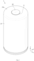
- FIG. 1 is a perspective view of a cylindrical secondary battery according to an embodiment of the present invention
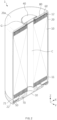
- FIG. 2 is a cutaway cross-sectional view of the cylindrical secondary battery according to an embodiment of the present invention.
- a cylindrical secondary battery 1 (hereinafter, referred to as 'secondary battery') according to an embodiment of the present invention may include an electrode assembly 10 and a battery can 20 accommodating the electrode assembly 10.
- the electrode assembly 10 may include a positive electrode, a negative electrode, and a separator interposed between the positive electrode and the negative electrode.
- the electrode assembly 10 may be provided with a first electrode tab 11 connected to one of the positive electrode and the negative electrode, and a second electrode tab 12 connected to the other of the positive electrode and the negative electrode.
- the electrode assembly 10 may be a jelly-roll type.
- the electrode assembly 10 may be manufactured by winding a stack in which the positive electrode, the separator, the negative electrode, and the separator are sequentially stacked.
- the electrode assembly 10 may preferably have a height-to-diameter ratio of 1 or more, but is not limited thereto.
- a hollow C defined to be elongated in a height direction may be defined in a center of the electrode assembly 10.
- the separator may be disposed at the outermost side of the electrode assembly 10.
- the first electrode tab 11 and the second electrode tab 12 may be provided on opposite ends of the electrode assembly 10 in the height direction, respectively.
- a non-coating portion of any one of the positive electrode and the negative electrode may be disposed on one end of the electrode assembly 10 to function as a first electrode tab 11.
- the non-coating portion of the other of the positive electrode and the negative electrode may be disposed on the other end of the electrode assembly 10 to function as a second electrode tab 12.
- Each of the electrode tabs 11 and 12 may extend along a winding direction of the electrode assembly 10.
- each of the electrode tabs 11 and 12 may include a plurality of foil-flags disposed along the winding direction of the electrode assembly 10.
- a first collector 50 to be described later may be coupled to the first electrode tab 11, and a second collector 60 to be described later may be coupled to the second electrode tab 12.
- the electrode assembly 10 may be accommodated in the battery can 20 in a state in which the collectors 50 and 60 are coupled to the electrode tabs 11 and 12, respectively.
- the first electrode tab 11 may be a non-coating portion of the negative electrode
- the second electrode tab 12 may be a non-coating portion of the positive electrode
- the first collector 50 may be referred to as a negative electrode collector
- the second collector 60 may be referred to as a positive electrode collector.
- the battery can 20 may have a substantially cylindrical shape.
- One surface 20a may be provided at one side of the battery can 20 in the height direction, and an opening may be defined at the other side.
- the electrode assembly 10 may be accommodated in the battery can 20 together with an electrolyte through the opening.
- the battery can 20 may have a conductive material such as a metal.
- the battery can 20 may be electrically connected to the first electrode tab 11 through the first collector 50 to be described later.
- the battery can 20 may have the same polarity as the first electrode tab 11.
- a beading part 21 and a crimping part 22 may be provided on the battery can 20.
- the beading part 21 and the crimping part 22 may be disposed adjacent to the opening of the battery can 20.
- the beading part 21 may be disposed by press-fitting a circumference of the battery can 20 to the inside of a radius thereof.
- An inner diameter of the beading part 21 may be less than an inner diameter of the battery can 20.
- the beading part 21 may be provided in a state in which the electrode assembly 10 is accommodated in the battery can 20.
- the electrode assembly 10 may be restricted between the one surface 20a of the battery can 20 and the beading part 21 in the height direction of the battery can 20.
- the beading part 21 may prevent the electrode assembly 10 from being separated from the opening of the battery can 20.
- the beading part 21 may be coupled to the first collector 50.
- the first collector 50 may be welded to the beading part 21.
- the first collector 50 may electrically connect the first electrode tab 11 to the battery can 20.
- the crimping part 22 may be disposed adjacent to the beading part 21.
- the crimping part 22 may be provided by bending an end of a circumferential surface of the battery can 20 toward the inside of a radius thereof.
- the crimping part 22 may be formed after the first collector 50 is coupled to the beading part 21.
- the crimping part 22 may restrict a cap plate 30 to be described later together with the beading part 21.
- the secondary battery 1 may include the cap plate 30 covering the opening of the battery can 20.
- the cap plate 30 may have a substantially circular plate shape.
- the cap plate 30 may define an outer appearance of the secondary battery 1 together with the battery can 20.
- An edge portion of the cap plate 30 may be restricted between the beading part 21 and the crimping part 22 of the battery can 20.
- the cap plate 30 may have a material having high rigidity such as a metal.
- the cap plate 30 may be insulated from the battery can 20 and may not have a polarity.
- a sealing part 72 of a spacer 70 to be described below may be interposed between the cap plate 30 and the battery can 20. This will be described in detail later.
- the secondary battery 1 may include a terminal 40 fixed by passing through the one surface 20a of the battery can 20.
- the terminal 40 may pass through the one surface 20a of the battery can 20, more specifically, a center of the one surface 20a. A portion of the terminal 40 may be exposed to the outside of the battery can 20, and the other portion of the terminal 40 may be disposed inside the battery can 20. For example, the terminal 40 may be fixed to the one surface 20a of the battery can 20 by riveting.
- the terminal 40 may have a conductive material such as a metal.
- the terminal 40 may be coupled to the second collector 60 to be described later.
- the second collector 60 may be welded to the terminal 40.
- the second collector 60 may electrically connect the second electrode tab 12 to the terminal 40.
- the terminal 40 may be insulated from the battery can 20.
- an insulating gasket G may be interposed between the terminal 40 and the battery can 20.
- an insulating coating layer may be disposed on a portion of the terminal 40, or a method for structurally fixing the terminal 40 may be applied while spacing the terminal 40 and the battery can 20 apart from each other.
- the insulating gasket G may be deformed during the riveting of the terminal 40 and then be bent toward an inner surface of the one surface 20a of the battery can 20.
- the insulating gasket G may seal a gap between the terminal 40 and the battery can 20.
- the battery can 20 and the terminal 40 may have polarities opposite to each other due to the insulating gasket G.
- the battery can 20 may have the same polarity as the first electrode tab 11, and the terminal 40 may have the same polarity as the second electrode tab 12.
- the one surface 2a of the battery can 20 may function as a first terminal having a first polarity
- the terminal 40 may function as a second terminal having a second polarity. Since the one surface 2a of the battery can 20 and the terminal 40 are disposed adjacent to each other, an inner space required for installing a bus bar in the battery module including the plurality of secondary batteries 1 may be reduced, and thus, energy density of the battery module may increase.
- the secondary battery 1 may include the first collector 50 electrically connecting the first electrode tab 11 to the battery can 20.
- the first electrode tab 11 may be connected to the negative electrode of the electrode assembly 10, and the first collector 50 may be referred to as a negative electrode collector.
- the secondary battery 1 may include the second collector 60 electrically connecting the second electrode tab 11 to the terminal 40.
- the second electrode tab 12 may be connected to the positive electrode of the electrode assembly 10, and the second collector 60 may be referred to as a positive collector.
- the first collector 50 and the second collector 60 may be disposed within the battery can 20.
- the first collector 50 may be disposed between the electrode assembly 10 and the cap plate 30 in the height direction of the battery can 20.
- the first collector 50 may be coupled to the first electrode tab 11.
- the first collector 50 may be welded to the first electrode tab 11.
- the first collector 50 may be welded to the battery can 20, more specifically, to the beading part 21.
- the second collector 60 may be disposed between the electrode assembly 10 and the one surface 20a of the battery can 20 in the height direction of the battery can 20.
- the second collector 60 may be coupled to the second electrode tab 12.
- the second collector 60 may be welded to the second electrode tab 12.
- the second collector 60 may be welded to the terminal 40.
- the secondary battery 1 may include a spacer 70 disposed between the cap plate 30 and the electrode assembly 10.
- the spacer 70 may be disposed between the cap plate 30 and the first collector 50.
- a height of the spacer 70 may correspond to a distance between the cap plate 30 and the electrode assembly 10.
- the spacer 70 may prevent the electrode assembly 10 from moving or shaking within the battery can 20.
- the secondary battery 1 may include an insulator 80 disposed between the electrode assembly 10 and the battery can 20.
- the insulator 80 may be disposed between the second collector 60 and the battery can 20.
- the insulator 80 may insulate the second collector 60 and the electrode assembly 10 from the battery can 20.
- the insulator 80 may have a resin material having insulating properties.
- a hole through which the terminal 40 passes may be defined in a center of the insulator 80.
- the terminal 40 may be coupled to the second collector 60 through the hole.
- the insulator 80 may have a substantially cap shape. In this case, a portion of the insulator 80 may be disposed between the one surface 20a of the battery can 20 and the second collector 60, and the other portion of the insulator 80 may be disposed between an outer circumference of the second collector 60 and an inner circumference of the battery can 20.
- the insulator 80 may have a plate shape disposed between the one surface 20a of the battery can 20 and the second collector 60.
- an insulating tape that is separated from the insulator 80 may be interposed between the outer circumference of the second collector 60 and the inner circumference of the battery can 20.
- a height of the insulator 80 may correspond to a vertical distance between the one surface 20a of the battery can 20 and the electrode assembly 10.
- the insulator 80 together with the spacer 70 may prevent the electrode assembly 10 from moving or shaking within the battery can 20.
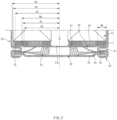
- FIG. 3 is an enlarged cross-sectional view of the first collector and surroundings of the first collector, which are illustrated in FIG. 2
- FIG. 4 is a perspective view of the first collector according to an embodiment of the present invention.
- the first collector 50 may be coupled to the first electrode tab 11.
- at least a portion of the first electrode tab 11 may be bent toward a hollow C of the electrode assembly 10, and the first collector 50 may be coupled to the bent portion of the first electrode tab 11.
- bent portions of the plurality of first electrode tabs 11 adjacent to each other may overlap each other.
- a height of the first electrode tab 11 may be reduced, and energy density of the secondary battery 1 may be improved.
- a coupling area between the first electrode tab 11 and the first collector 50 increases, coupling force between the first electrode tab 11 and the first collector 50 may be improved to reduce resistance.
- the first collector 50 may include a center part 51, a tab coupling part 52 extending outward from the center part 51 and coupled to the first electrode tab 11, a can coupling part 53 coupled to the battery can 20 and spaced apart from the tab coupling part 52, and a bridge 54 connecting the can coupling part 53 to the center part 51.
- the center part 51 may be disposed at a center of one side (e.g., lower side) of the electrode assembly 10.
- the center part 51 may have an approximately circular shape.
- a center hole 51a may be defined in the center part 51.
- the center hole 51a may face the hollow C of the electrode assembly 10.
- the center hole 51a together with the hollow C may function as a passage for insertion of a welding rod for the coupling between the terminal 40 and the second collector 60 or laser irradiation.
- the center hole 51a may function as a passage through which an electrolyte is smoothly impregnated into the electrode assembly 10 when the electrolyte is injected.
- the tab coupling part 52 may be expanded radially outward from the center part 51.
- the tab coupling part 52 may be coupled to the first electrode tab 11.
- the tab coupling part 52 may be provided in plurality, and the plurality of tab coupling parts 52 may be radially expanded from the center part 51.
- a width of the tab coupling part 52 may increase as a distance from the center part 51 increases.
- the tab coupling part 52 may widely cover the bent portion of the first electrode tab 11 and may prevent the bent portion of the first electrode tab 11 from being lifted.
- Central axes of each of the electrode assembly 10, the battery can 20, and the first collector 50 may substantially coincide with each other.
- a distance R1 from the central axis of the electrode assembly 10 to an outer edge of the tab coupling part 52 may be less than a radius Ra of the electrode assembly 10 and also be equal to or less than an inner radius Rb of the beading part 21 in the radial direction of the battery can 20.
- the outer edge of the tab coupling part 52 may have an arc shape having a first curvature radius R1.
- a center of curvature of the outer edge may coincide with the center of the first collector 50.
- the first curvature radius R1 may be less than the radius Ra of the electrode assembly 10. In addition, the first curvature radius R1 may be less than the inner radius Rb of the beading part 21 disposed on the battery can 20.
- the tab coupling part 52 may non-overlap the beading part 21 in the height direction of the battery can 20. That is, the tab coupling part 52 may not be disposed between the electrode assembly 10 and the beading part 21. Thus, it is possible to prevent the tab coupling part 52 from being damaged by being jammed between the electrode assembly 10 and the beading part 21 due to a sizing process.
- the sizing refers to a compression process of reducing a height of the beading part 21 to reduce a height of the secondary battery 1 after the beading part 21 and the crimping part 22 are formed on the battery can 20 in which the electrode assembly 10 is accommodated.
- the distance R1 from the central axis of the electrode assembly 10 to the outer edge of the tab coupling part 52 may be equal to or greater than 2/3 of the radius Ra of the electrode assembly 10.
- the first curvature radius R1 may be 2/3 or more of the radius Ra of the electrode assembly 10.
- Both edges of the tab coupling part 52 may be disposed along the radial direction of the first collector 50.
- a virtual line extending along both the edges may pass through the center of the first collector 50.
- An injection hole 52d may be defined in the tab coupling part 52. The impregnation of the electrolyte into the electrode assembly 10 may be improved by the injection hole 52d.
- the width of the injection hole 52d may increase as a distance from the center part 51 increases.
- the electrolyte may be impregnated more uniformly with respect to the electrode assembly 10 in which a winding length per unit angle becomes longer toward the outside of the radius.
- the can coupling part 53 may be coupled to the battery can 20, more specifically to the beading part 21.
- the can coupling part 53 may be coupled to a surface disposed relatively far from the electrode assembly 10 on the beading part 21.
- the can coupling part 53 may have a predetermined height difference with respect to the center part 51 and the tab coupling part 52.
- the height difference may mean a distance between the tab coupling part 52 and the can coupling part 53 with respect to the height direction of the battery can 20.
- the height difference may correspond to the height of the beading part 21. That is, the distance between the tab coupling part 52 and the can coupling part 53 in the height direction of the battery can 20 may be the same as or similar to the height of the beading part 21.
- the can coupling part 53 may be pressed by a sealing part 72 to be described later.
- the can coupling part 53 may be interposed and fixed between the sealing part 72 and the beading part 21.
- the can coupling part 53 may be spaced apart from the tab coupling part 52.
- each of the can coupling part 53 and the tab coupling part 52 may be only connected to the center part 51, and the can coupling part 53 and the tab coupling part 52 may not be directly connected to each other.
- the can coupling part 53 may be provided in plurality.
- the can coupling part 53 and the tab coupling part 52 may be alternately disposed in a circumferential direction of the first collector 50.
- the can coupling part 53 may extend along the inner circumference of the battery can 20. That is, the can coupling part 53 may extend in the circumferential direction of the beading part 21. Thus, since a contact area between the can coupling part 53 and the beading part 21 increases, the can coupling part 53 and the beading part 21 may be stably coupled to each other, and the resistance between the can coupling part 53 and the beading part 21 may decrease.
- a distance R2 from the central axis of the electrode assembly 10 to the outer edge of the can coupling part 53 may be greater than the distance R1 from the central axis of the electrode assembly 10 to the outer edge of the tab coupling part 52 in the radial direction of the battery can 20.
- a distance R3 from the central axis of the electrode assembly 10 to the inner edge of the can coupling part 53 may be less than the distance R2 from the central axis of the electrode assembly 10 to the outer edge of the can coupling part 53 in the radial direction of the battery can 20.
- the outer edge of the can coupling part 53 may have an arc shape having a second curvature radius R2 greater than the first curvature radius R1 described above.
- the inner edge of the can coupling part 53 may have an arc shape having a third curvature radius R2 less than the second curvature radius R2.
- the center of curvature of the outer edge and the inner edge of the can coupling part 53 may substantially coincide with the central axis of the electrode assembly 10.
- the second curvature radius R2 may be greater than the inner radius Rb of the beading part 21 disposed on the battery can 20, and the third curvature radius R3 may be less than the inner radius Rb of the beading part 21. That is, the distance R2 from the central axis of the electrode assembly 10 to the outer edge of the can coupling part 53 may be greater than the inner radius Rb of the beading part 21, and the distance R3 from the central axis of the electrode assembly 10 to the inner edge of the can coupling part 53 may be less than the inner radius Rb of the beating part 21 in the radial direction of the battery can 20.
- the second curvature radius R2 is equal to or less than the inner radius Rb of the beading part 21, it may be difficult to couple the can coupling part 53 to the beading part 21. If the third curvature radius R3 is equal to or greater than the inner radius Rb of the beading part 21, interference may occur between the bridge 54 to be described later and the beading part 21.
- Both edges of the can coupling part 53 may be disposed along the radial direction of the first collector 50.
- a virtual line extending along both the edges may pass through the center of the first collector 50.
- the can coupling part 53 and the tab coupling part 52 may non-overlap each other in the height direction of the battery can 20. Thus, when the plurality of first collectors 50 that is in a state before being coupled to the electrode assembly 10 are loaded, the can coupling parts 53 of one first collector 50 and the tab coupling part 52 of the other first collector 50 may be prevented from interfering with each other.
- Coupling strength between the can coupling part 53 and the battery can 20, more specifically, between the can coupling part 53 and the beading part 21, may be greater than that between the tab coupling part 52 and the first electrode tab 11.
- the can coupling part 53 may be stably coupled to the rigid battery can 20.
- the bridge 54 may connect the can coupling part 53 to the center part 51.
- the bridge 54 may extend radially outward from the center part 51 and may be spaced apart from the tab coupling part 52 in the circumferential direction of the first collector 50.
- the bridge 54 may be provided in plurality, like the can coupling part 53, and the plurality of bridges 54 may extend radially from the center part 51.
- the bridges 54 and the tab coupling parts 52 may be alternately disposed in the circumferential direction of the first collector 50.
- the bridge 54 may be inclined.
- the bridge 54 may obliquely extend in a direction away from the electrode assembly 10 as the distance from the center part 51 increases.
- the bridge 54 may include a first inclined part 54a extending from the center part 51 and a second inclined part 54b extending from the first inclined part 54a and having a gentler inclination than the first inclined part 54a.
- the bridge 54 may be rounded in a direction that becomes gentler as the distance from the center part 51 increases.
- the bridge 54 it is possible to prevent the bridge 54 from being excessively deformed due to the sizing process and prevent the center part 51 and the first electrode tab 11 coupled to the center part 51 from being lifted.
- the tab coupling part 53 coupled to the beading part 21 may also move toward the electrode assembly 10.
- repulsive force in a direction away from the electrode assembly 10 may act on the center part 51 connected to the tab coupling part 53 and the bridge 54.
- the bridge 54 may minimize the lifting of the center part 51 and the first electrode tab 11, which is caused by the sizing process.
- a process of press-fitting the outer circumference of the battery can 20 to the inside of the radius to form the beading part 21 may be performed in a state in which the electrode assembly 10 to which the first collector 50 is coupled is accommodated in the battery can 20.
- the bridge 54 since the bridge 54 is gently inclined as it moves away from the center part 51, the beading part 21 may be easily formed without interfering with the bridge 54.
- An edge of the cap plate 30 may be disposed between the beading part 21 and the crimping part 22 of the battery can 20 and may be fixed by a sealing part 72 to be described later.
- the cap plate 30 may not protrude from the battery can 20.
- a bottom surface of the plate part 31 of the cap plate 30 may be disposed on the same surface as the bottom surface of the battery can 20 or be disposed higher than the bottom surface of the battery can 20.
- the cap plate 30 may not be pressed upward by the bottom surface supporting the battery can 20, and a phenomenon in which a pressure required for rupturing the venting part 34 due to a weight of the secondary battery 1 is different from a design value may be prevented from occurring.
- a venting part 34 may be provided in the cap plate 30.
- the venting part 34 may have a thickness less than that of the surrounding area.
- the venting part 34 may be structurally weak compared to a surrounding area thereof, and if an internal pressure of the battery can 20 increases beyond a preset value, the venting part 34 may be preferentially ruptured.
- the venting part 34 may be disposed along a circumferential direction of the cap plate 30.
- the venting part 34 may have a closed loop shape such as a ring. Therefore, when the venting part 34 is ruptured, an area of the cap plate 30 disposed inside the venting part 34 may be easily separated to form an opening, and a gas in the battery can 20 may be quickly discharged.
- the venting part 34 may be formed by notching both surfaces of the cap plate 30 to a predetermined depth to partially reduce the thickness of the cap plate 30. However, it is not limited thereto, and it may be possible to form the venting part 34 by notching only one surface of the cap plate 30.
- the spacer 70 may have an elastic material.
- the spacer 70 may correspond to a distance between the first collector 50 and the cap plate 30.
- the body part 71 may effectively prevent the electrode assembly 10 from moving within the battery can 20 due to a gap defined between the first collector 50 and the cap plate 30. Therefore, the spacer 70 may prevent a coupled portion between the electrode assembly 10 and the first collector 50 and/or a coupled portion between the first collector 50 and the battery can 20 from being damaged.
- An opening facing a hollow C of the electrode assembly 10 may be defined in the spacer 70 through a center hole 51a of the first collector 50.
- the opening together with the center hole 51a and the hollow C may function as a passage for inserting a welding rod or a passage for laser irradiation.
- the opening may function as a passage through which an electrolyte is smoothly impregnated into the electrode assembly 10 when the electrolyte is injected.
- the sealing part 72 may be integrated with the spacer 70. However, this embodiment is not limited thereto.
- the sealing part 72 may have a circular ring shape extending along an inner circumference of the battery can 20.
- the sealing part 72 may be fixed between the beading part 21 and the crimping unit 22 of the battery can 20.
- a portion of the sealing part 72 may be bent together with a crimping part 22 to fix an edge of the cap plate 30.
- the sealing part 72 may firmly seal the gap between the cap plate 30 and the battery can 20.
- the sealing part 72 may function as a gasket for improving fixing force of the cap plate 30 and sealing force of the battery can 20.
- the sealing part 72 may press the can coupling part 53 of the first collector 50 toward the beading part 21 to further strengthen the coupling between the can coupling part 53 and the beading part 21.
- the sealing part 72 may insulate the can coupling part 53 from the cap plate 30.
- FIG. 5 is an enlarged cross-sectional view of a second collector and surroundings of the second collector, which are illustrated in FIG. 2
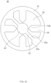
- FIG. 6 is a plan view of the second collector according to an embodiment of the present invention
- FIG. 7 is an enlarged view illustrating a narrow part illustrated in FIG. 6 .
- the terminal 40 may pass through a central portion of the one surface 20a of the battery can 20 and be coupled to the second collector 60 so as to be electrically connected to the second electrode tab 12.
- the terminal 40 may be insulated from the battery can 20 by an insulating gasket G.
- the terminal 40 may include a terminal part 41, a body part 42 and a protrusion 43.
- the terminal part 41 may be disposed outside the battery can 20.
- the terminal part 41 may be a portion to which a bus bar (not shown) disposed outside the battery can 20 can be connected.
- the terminal part 41 may have a substantially circular flat plate shape.
- the body part 42 may be integrated with the terminal part 41.
- the body part 42 may pass through the battery can 20 and be coupled to the second collector 60, a tab coupling part 64 to be described in more detail later.
- the body part 42 may have a substantially circular columnar shape.
- the protrusion 43 may protrude radially outward from a circumference of the body part 42 and may be disposed inside the battery can 20.
- the protrusion 43 may be integrated with the body part 42.
- the protrusion 43 may be disposed to be inclined in a direction closer to the second collector 60 as it moves away from an outer circumference of the body part 42.
- An end of the protrusion 43 may not protrude toward the second collector 60 more than an end of the body part 42. Therefore, it is possible to prevent the second collector 60 from being damaged by the protrusion 43.
- a diameter of each of the terminal part 41 and the protrusion 43 may be greater than a diameter of the body part 42.
- the terminal 40 may be fixed so as not to be separated from the battery can 20.
- the insulating gasket G may seal a gap between the terminal 40 and the battery can 20.
- the insulating gasket G may be bent along the terminal part 41 and the protrusion 43 and fixed between the battery can 20 and the terminal 40.
- the insulator 80 may insulate the second collector 60 from the battery can 20.
- the insulator 80 may be disposed between the second collector 60 and the battery can 20.
- the insulator 80 may include a plate part 81 and a circumferential part 82.
- the plate unit 81 may be disposed between the second collector 60 and the one surface 20a of the battery can 20.
- the plate part 81 may have an approximately circular plate shape.
- a hole through which the terminal 70 passes may be defined in a center of the plate part 81.
- the terminal 40 may be coupled to the second collector 60 toward the hole.
- An end of the protrusion 43 of the terminal 40 may face an inner circumference of the hole.
- the circumferential part 82 may protrude from an edge of the plate part 81 between the inner circumference of the battery can 20 and the outer circumference of the electrode assembly 10.
- the circumferential part 82 may be integrated with the plate part 81, but is not limited thereto.
- the circumferential part 82 may be disposed between the outer circumference of each of the second collector 60 and the second electrode tab 12 and the inner circumference of the battery can 20.
- a height of the circumferential part 82 in the height direction of the battery can 20 may be greater than the sum of the heights of the second electrode tab 12 and the second collector 60.
- the circumferential part 82 may reliably insulate the second electrode tab 12 and the second collector 60 from the battery can 20.
- Central axes of the electrode assembly 10, the battery can 20, and the second collector 60 may substantially coincide with each other.
- the second collector 60 may be coupled to the second electrode tab 12.
- at least a portion of the second electrode tab 12 may be bent toward a hollow C of the electrode assembly 10, and the second collector 60 may be coupled to the bent portion 12a of the second electrode tab 12.
- the bent portions 12a of the plurality of first electrode tabs 12 adjacent to each other may overlap each other.
- a height of the second electrode tab 12 may be reduced, and energy density of the secondary battery 1 may be improved.
- a coupling area between the second electrode tab 12 and the second collector 60 increases, coupling force between the second electrode tab 12 and the second collector 60 may be improved to reduce resistance.
- the second collector 60 may include an edge part 61, a terminal coupling part 62 disposed inside the edge part 61 and coupled to the terminal 40, a bridge 63 connecting the edge part 61 to the terminal coupling part 62, and a tab coupling part 64 extending inward from the edge part 61, spaced apart from the bridge 63 and the terminal coupling part 62, and coupled to the second electrode tab 12.
- the edge part 61 may have a substantially circular rim shape. However, this embodiment is not limited thereto.
- the edge part 61 may be disposed between the second electrode tab 12 and the insulator 80 in the height direction of the battery can 20.
- the terminal coupling part 62 may be disposed at an inner center of the edge part 61. At least a portion of the terminal coupling part 62 may face the hollow C of the electrode assembly 10.
- the terminal coupling part 62 may have a substantially circular shape.
- the terminal coupling part 62 may be coupled to the terminal 40, more specifically, to the body part 42 of the terminal 40.
- the terminal coupling part 62 may be welded to a bottom surface of the body part 42 of the terminal 40.
- the bridge 63 may connect the edge part 61 to the terminal coupling part 62.
- the bridge 63 may extend radially inward from the edge part 61.
- the bridge 63 may be provided in plurality, and the plurality of bridges 63 may extend radially from the terminal coupling part 62.
- a width of an outer end 63a of the bridge 63 may increase as it approaches the edge part 61.
- rigidity of a portion at which the bridge 63 and the circumferential part 61 are connected to each other may be improved.
- the outer end 63a of the bridge 63 having relatively high rigidity may be gripped and transported stably.
- the tab coupling part 64 may extend radially inward from the edge part 61.
- the tab coupling part 64 may be coupled to the second electrode tab 12.
- the tab coupling part 64 may be welded to the bent portion 12a of the second electrode tab 12.
- the tab coupling part 64 may be spaced apart from the terminal coupling part 62. In more detail, the tab coupling part 64 may be spaced apart from the terminal coupling part 62 in the radial direction of the second collector 60. In more detail, each of the tab coupling part 64 and the terminal coupling part 62 may be only connected to the circumferential part 61, and the tab coupling part 64 and the terminal coupling part 62 may not be directly connected to each other. As a result, when an impact or vibration is applied to the secondary battery 1, since stress applied to the coupling area between the tab coupling part 64 and the second electrode tab 12 and the coupled portion between the terminal coupling part 62 and the terminal 40 are dispersed, possibility of occurrence of damage of the second collector 60 may be minimized.
- the tab coupling part 64 may be spaced apart from the bridge 63. In more detail, the tab coupling part 64 may be spaced apart from the bridge 63 in the circumferential direction of the second collector 60.
- the tab coupling part 64 may be provided in plurality. In the case of the present embodiment, the number of tab coupling parts 64 and the number of bridges 63 may be the same. The bridges 63 and the tab coupling parts 64 may be alternately disposed in the circumferential direction of the second collector 60. Each of the bridges 63 may be disposed between a pair of tab coupling parts 64 adjacent to each other in the circumferential direction of the second collector 60.
- a width w2 of the bridge 63 may be less than or equal to a width w4 of the tab coupling part 64. As a result, electrical resistance may increase in the bridge 63, and when overcurrent occurs, a portion of the bridge 63 is ruptured to block the overcurrent.
- a narrow part 63b having a relatively narrow width may be provided in the bridge 63.
- the narrow part 63b may be provided by recessing grooves in both edges of the bridge 63.
- a width w3 of the narrow part 63b may be narrower than the width w2 of the bridge 63. Also, the width w3 of the narrow part 63b may be narrower than the width w1 of the edge part 61.
- the narrow part 63b when the electrical resistance increases in the narrow part 63b, and the overcurrent flows through the bridge 63, the narrow part 63b is ruptured preferentially rather than the edge part 61 and the bridge 63 to reliably block the overcurrent. That is, the narrow part 63b may perform a fuse function.
- the width w3 of the narrow part 63b may be 70% to 80% of the width w2 of the bridge 63.
- the high reliability of the fuse function may be maintained while maintaining sufficient high rigidity of the narrow part 63b.
- the width w3 of the narrow part 63b is less than 70% of the width w2 of the bridge 63, there is a concern that the narrow part 63b is easily ruptured when the impact or vibration is applied to the secondary battery 1.
- the width w3 of the narrow part 63b is greater than 80% of the width w2 of the bridge 63, there is a concern that the narrow part 63b may not ruptured preferentially when the overcurrent flows.
- the narrow part 63b may face the bent portion 12a of the second electrode tab 12 with respect to the height direction of the electrode assembly 10.
- the bent portion 12a of the second electrode tab 12 may prevent residues generated when the narrow part 63b is ruptured from being introduced into the electrode assembly 10.
- the narrow part 63b may be disposed closer to the outer end 63a of both the ends of the bridge 63.
- a distance d from the center of the second collector 60 to the narrow part 63b is 0.4 times to 0.9 times the radius Ra of the electrode assembly 10 in the radial direction of the second collector 60. That is, a distance d from the central axis of the electrode assembly 10 to the narrow part 63b is 0.4 times to 0.9 times the radius Ra of the electrode assembly 10 in the radial direction of the electrode assembly 10.
- the bent portions 12a of the second electrode tab 12 may overlap each other. In this case, in some areas adjacent to the outer circumference of the electrode assembly 10 and in some areas adjacent to the hollow C, an overlapping degree or number of bent portions 12a of the second electrode tab 12 may be reduced. For this reason, if the distance d from the center of the second collector 60 to the narrow part 63b is less than 0.4 times or larger than 0.9 times the radius Ra of the electrode assembly 10, the residues generated when the narrow part 63b is ruptured may be introduced into the electrode assembly 10.
- the narrow part 63b may face the area on which the bent portions 12a of the second electrode tab 12 sufficiently overlap each other in the height direction of the electrode assembly 10.
- At least one opening 65 may be defined between the edge part 61 and the terminal coupling part 62.
- a plurality of openings 65 divided into a plurality of areas by the plurality of bridges 63 may be defined.
- the tab coupling part 64 may reduce a surface area of the opening 65.
- a ratio occupied by a surface area of the at least one opening 65 to the total surface area of the second collector 60 may be 40% to 99%.
- the total surface area of the second collector 60 may mean that sum of all values of respective surface areas of the edge part 61, the terminal coupling part 62, the bridge 63, the tab coupling part 64, and the opening portion 65.
- impregnation of the electrolyte into the electrode assembly 10 may be improved by the opening 65. If the surface area of at least one opening 65 is less than 40% of the total surface area of the second collector 60, the impregnation of the electrolyte into the electrode assembly 10 may be deteriorated.
- the inner end 64a of the tab coupling part 64 may be spaced a predetermined apart from the terminal coupling part 62 to define a predetermined gap. A width of the inner end 64a of the tab coupling part 64 may decrease as it approaches the terminal coupling part 62. As a result, the surface area of the opening 65 may further increase, and the impregnation of the electrolyte into the electrode assembly 10 may be improved.
- a width w1 of the edge part 61 may be narrower than a width w4 of the tab coupling part 64.
- a radius R5 of the second collector 60 may be 33% to 102% of the radius Ra of the electrode assembly 10. In addition, the radius R5 of the second collector 60 may be 33% to 98.5% of an inner radius Rd of the battery can 20. The radius R5 of the second collector 60 may mean a distance from the center of the second collector 60 to the outer circumference of the edge part 61.
- radius R5 of the second collector 60 is less than 33% of the radius Ra of the electrode assembly 10 or less than 33% of the inner radius Rd of the battery can 20, a function as a an electrical passage of the second collector 60 connecting the second electrode tab 12 to the terminal 40 may be deteriorated.
- the edge part 61 of the second collector plate 60 may interfere with the edge part 82 of the insulator 80, and if a size of the battery can 20 increases, or a size of the electrode assembly 10 decreases in order to prevent the interference, the energy density of the secondary battery 1 may decrease.
- the radius R4 of the terminal coupling part 62 may be 40% to 320% of the radius Rc of the body part 42 coupled to the terminal coupling part 62 at the terminal 40.
- the radius R4 of the terminal coupling part 62 may be 40% to 320% of the radius Rc of the bottom surface of the body part 42.
- the coupling area between the terminal coupling part 62 and the terminal 40 becomes too small, resulting in increasing in resistance.
- the radius R4 of the terminal coupling part 62 is greater than 320% of the radius Rc of the body part 42, a length of the tab coupling part 64 spaced apart from the terminal coupling part 62 may be shortened, and the surface area of the opening 65 may be reduced. As a result, the coupling area between the second electrode tab 12 and the tab coupling part 64 may decrease to increase in resistance, and the impregnation of the electrolyte into the electrode assembly 10 may decrease.
- a difference between the coupling area between the first electrode tab 11 and the first collector 50 (see FIG. 3 ) and the coupling area between the second electrode tab 12 and the second collector 60 may be three times or less.
- the coupling area between the first electrode tab 11 and the first collector 50 may be referred as a first coupling area
- the coupling area between the second electrode tab 12 and the second collector 60 may be referred to as a second coupling area.
- the first coupling area may be a coupling area between the first electrode tab 11 and the tab coupling part 52 (see FIG. 4 ) of the first collector 50.
- the second coupling area may be a coupling area between the second electrode tab 12 and the tab coupling part 64 of the second collector 60.
- any one of the first coupling area and the second coupling area may be 3 times or less of the other one.
- the first coupling area may be the same as or similar to the second coupling area.
- the second collector 60 may non-overlap the beading part 21 (see FIG. 3 ) in the height direction of the electrode assembly 10.
- the second collector 60 may overlap the beading part 21 in the height direction of the electrode assembly 10, and a width of an area overlapping the second collector 60 on the beading part 21 may be 80% or less of a width wb of the beading part 21. That is, the second collector 60 may overlap by 80% or less of the width wb of the beading part 21 in the height direction of the electrode assembly 10.
- the width wb of the beading part 21 may mean the width of the battery can 20 in the radial direction.
- the second collector 60 may interfere with the circumferential part 82 of the insulator 80, and thus, in order to prevent the interference, if the battery can increases in size, or the electrode assembly 10 decreases in size, the energy density of the secondary battery 1 may be reduced.
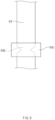
- FIG. 8 is a view illustrating a modified example of the narrow part illustrated in FIG. 6 .
- the narrow part 63b may be provided by recessing the grooves on both edges of the bridge 63. However, it is not limited thereto, and as illustrated in FIG. 8 , the narrow part 63b may be provided by penetrating the bridge 63.
- a hole may be defined in the central portion of the bridge 63 in the width direction, and both sides of the hole may constitute the narrow part 63b.
- the width w3 of the narrow part 63b may mean a sum of a width w31 of one side of the hole and a width w32 of the other side of the hole.
- the width w3 of the narrow part 63b the above description is cited.
- FIG. 9 is a view illustrating a state in which a cover member surrounds the narrow part illustrated in FIG. 6 .
- a cover member 63c made of an insulating material may be provided on the bridge 63 of the second collector 60 to cover the narrow part 63b.
- the cover member 63c may be a tape taped to cover the narrow part 63b.
- the cover member 63c may prevent the residues generated when the bridge 63, particularly the narrow part 63b is ruptured by the overcurrent from being spread to the surroundings.
- thermal conductivity of the cover member 63c may be less than that of the bridge 63.
- the cover member 63c may include a polyimide (PI) material. Since the polyimide (PI) material has a melting point of approximately 375 degrees Celsius to 401 degrees Celsius, the cover member 63c may not be melted due to the heat generated by the bridge 63.
- PI polyimide
- a structure in which the narrow part 63b is not provided in the bridge 63, and the cover member 63c covers a specific point of the bridge 63 is also possible.
- the cover member 63c deteriorates the heat dissipation at a specific point of the bridge 63, when the overcurrent flows through the bridge 63, an amount of heat generated at the specific point may increase and thus be preferentially ruptured. That is, the specific point of the bridge 63 surrounded by the cover member 63c may perform a fuse function.
- the cover member 63c may be disposed closer to the outer end 63a of both the ends of the bridge 63. Also, the cover member 63c may face the bent portion 12a of the second electrode tab 12 in the axial direction of the electrode assembly 10.
- a distance d from the center of the second collector 60 to the cover member 63b is 0.4 times to 0.9 times the radius Ra of the electrode assembly 10 in the radial direction of the second collector 60.
- FIG. 10 is a plan view of a second collector according to another embodiment of the present invention.
- the number of bridges 63 may be less than the number of tab coupling parts 64.
- some of the plurality of tab coupling parts 64 may be continuously disposed in a circumferential direction of the second collector 60. That is, the tab coupling parts 64 and the bridges 63 may not be alternately disposed in the circumferential direction of the second collector 60.
- the bridge 63 may be disposed between a pair of tab coupling parts 64 adjacent to each other in the circumferential direction of the second collector 60.
Landscapes
- Chemical & Material Sciences (AREA)
- Chemical Kinetics & Catalysis (AREA)
- Electrochemistry (AREA)
- General Chemical & Material Sciences (AREA)
- Engineering & Computer Science (AREA)
- Manufacturing & Machinery (AREA)
- Connection Of Batteries Or Terminals (AREA)
- Sealing Battery Cases Or Jackets (AREA)
Abstract
Description
- The present application claims the benefit of the priority of
Korean Patent Application No. 10-2022-0010936, filed on January 25, 2022 - The present invention relates to a collector and a cylindrical secondary battery including the same.
- A cylindrical secondary battery according to a related art generally has a structure in which a tab connecting a jelly-roll to an external terminal is welded to a foil of the jelly-roll. The cylindrical secondary battery having such a structure has a limited current path, and self-resistance of the jelly-roll is inevitably very high.
- Thus, since a method for reducing resistance by increasing in number of tabs connecting the jelly-roll to an external terminal has been tried, there is a limit to reduce resistance to a desired level and sufficiently secure a path of current only by increasing in number of tabs as described above.
- Thus, it is necessary to develop a new jelly-roll structure and a structure of a collector suitable for the jelly-roll structure in order to reduce the self-resistance of the jelly-roll. Particularly, the jelly-roll having the new structure and the application of the collector are more necessary for devices that require a battery pack having high output/high capacity such as, for example, an electric vehicle.
- In addition, in the case of the battery pack applied to the electric vehicle and the like, it is inevitably exposed to a lot of vibration and impact when considering the use environment. Therefore, there is a need to develop a cylindrical secondary battery having a structure in which there is little risk of damage to a welded portion even when vibration and an external impact are applied, and a collector structure applied to the cylindrical secondary battery.
- One object to be implemented by the present invention is to provide a collector having a structure suitable for an electrode assembly having a low resistance structure, and a cylindrical secondary battery including the same.
- Another object to be implemented by the present invention is to provide a collector having a structure that is capable of reducing possibility of damage to a welded portion with an electrode assembly and/or a welded portion with a battery can even when vibration and an impact are applied, and a cylindrical secondary battery including the same.
- A cylindrical secondary battery according to an embodiment of the present invention may include: an electrode assembly provided with an electrode tab; a battery can configured to accommodate the electrode assembly; a terminal configured to pass through the battery can and insulated from the battery can; and a collector configured to electrically connect the electrode tab to the terminal. The collector may include: an edge part; a terminal coupling part located inside the edge part and coupled to the terminal; a bridge connecting the edge part to the terminal coupling part; and a tab coupling part extending inward from the edge part, spaced apart from the bridge and the terminal coupling part, and coupled to the electrode tab. An inner end of the tab coupling part may have a width that gradually decreases as it approaches the terminal coupling part.
- The bridge and the tab coupling part may be alternately disposed in a circumferential direction of the collector.
- The outer end of the bridge may have a width that gradually increases as it approaches the edge part.
- A narrow part having a relatively narrow width may be provided in the bridge.
- The narrow part may have a width corresponding to 70% to 80% of a width of the bridge.
- The narrow part may be disposed closer to an outer end of opposite ends of the bridge.
- In a radial direction of the collector, a distance from a center of the collector to the narrow part may be 0.4 times to 0.9 times a radius of the electrode assembly.
- At least a portion of the electrode tab may be bent toward a central axis of the electrode assembly, and the narrow part may face the bent portion of the electrode tab in an axial direction of the electrode assembly.
- The narrow part may be defined by recessing grooves at both edges of the bridge or penetrating the bridge.
- The narrow part may have a width less than that of the edge part.
- The bridge may be provided with a cover member configured to surround the bridge and made of an insulating material having thermal conductivity less than that of the bridge.
- The cover member may be made of a polyimide (PI) material.
- The edge part may have a width less than a width of the tab coupling part.
- The collector may have a radius corresponding to 33% to 102% of a radius of the electrode assembly.
- The collector may have a radius corresponding to 33% to 98.5% of an inner radius of the battery can.
- The terminal coupling part may have a radius corresponding to 40% to 320% of a radius of a body part of the terminal, the body part being coupled to the terminal coupling part.
- At least one opening may be defined between the edge part and the terminal coupling part, and a ratio of a surface area of the at least one opening to a total surface area of the collector may be 40% to 99%.
- A collector according to an embodiment of the present invention may electrically connect an electrode assembly to a terminal passing through a battery can in which the electrode assembly is accommodated. The collector may include: an edge part; a terminal coupling part located inside the edge part and coupled to the terminal; a bridge connecting the edge part to the terminal coupling part; and a tab coupling part extending inward from the edge part, spaced apart from the bridge and the terminal coupling part, and coupled to an electrode tab provided in the electrode assembly. An inner end of the tab coupling part may have a width that gradually decreases as it approaches the terminal coupling part.
- A cylindrical secondary battery according to an embodiment of the present invention may include: an electrode assembly provided with a first electrode tab and a second electrode tab; a battery can configured to accommodate the electrode assembly; a terminal configured to pass through the battery can and insulated from the battery can; a first collector configured to electrically connect the first electrode tab to the battery can; and a second collector configured to electrically connect the second electrode tab to the terminal. A difference between a coupling area between the first electrode tab and the first collector and a coupling area between the second electrode tab and the second collector may be three times or less.
- A beading part press-fitted between the cap plate and the electrode assembly may be disposed on a circumference of the battery can, and a can coupling part of the first collector may be coupled to the beading part.
- The second collector may non-overlap the beading part in a height direction of the electrode assembly.
- The second collector may overlap the beading part in a height direction of the electrode assembly, and a width of an area of the beading part, which overlaps the second collector, may be 80% or less of a width of the beading part.
- According to the preferred embodiment of the present invention, when the electrode assembly and the battery can are electrically connected to each other, the resistance may be significantly reduced.
- In addition, even when the vibration and impact are applied while the secondary battery is used, the possibility of damage to the welded portion between the collector and the electrode assembly and/or the welded portion between the collector and the battery can may be significantly reduced.
- In addition, the effects that are obvious to those skilled in the art may be predicted from the configurations according to the embodiment of the present invention.
- The following drawings attached in this specification illustrate a preferred embodiment of the present invention and function to make further understood the technical spirit of the present invention along with the detailed description of the invention, and thus, the present invention should not be construed as being limited to only the drawings.
-
FIG. 1 is a perspective view of a cylindrical secondary battery according to an embodiment of the present invention. -
FIG. 2 is a cutaway cross-sectional view of the cylindrical secondary battery according to an embodiment of the present invention. -
FIG. 3 is an enlarged cross-sectional view of a first collector and surroundings of the first collector, which are illustrated inFIG. 2 . -
FIG. 4 is a perspective view of the first collector according to an embodiment of the present invention. -
FIG. 5 is an enlarged cross-sectional view of a second collector and surroundings of the first collector, which are illustrated inFIG. 2 . -
FIG. 6 is a plan view of the second collector according to an embodiment of the present invention. -
FIG. 7 is an enlarged view illustrating a narrow part illustrated inFIG. 6 . -
FIG. 8 is a view illustrating a modified example of the narrow part illustrated inFIG. 6 . -
FIG. 9 is a view illustrating a state in which a cover member surrounds the narrow part illustrated inFIG. 6 . -
FIG. 10 is a plan view of a second collector according to another embodiment of the present invention. - Hereinafter, preferred embodiments of the present invention will be described in detail with reference to the accompanying drawings so that those of ordinary skill in the art can easily carry out the present invention. However, the present invention may be implemented in several different forms and is not limited or restricted by the following examples.
- In order to clearly explain the present invention, detailed descriptions of portions that are irrelevant to the description or related known technologies that may unnecessarily obscure the gist of the present invention have been omitted, and in the present specification, reference symbols are added to components in each drawing. In this case, the same or similar reference numerals are assigned to the same or similar elements throughout the specification.
- Also, terms or words used in this specification and claims should not be restrictively interpreted as ordinary meanings or dictionary-based meanings, but should be interpreted as meanings and concepts conforming to the scope of the present invention on the basis of the principle that an inventor can properly define the concept of a term to describe and explain his or her invention in the best ways.
-
FIG. 1 is a perspective view of a cylindrical secondary battery according to an embodiment of the present invention, andFIG. 2 is a cutaway cross-sectional view of the cylindrical secondary battery according to an embodiment of the present invention. - A cylindrical secondary battery 1 (hereinafter, referred to as 'secondary battery') according to an embodiment of the present invention may include an
electrode assembly 10 and a battery can 20 accommodating theelectrode assembly 10. - The
electrode assembly 10 may include a positive electrode, a negative electrode, and a separator interposed between the positive electrode and the negative electrode. In addition, theelectrode assembly 10 may be provided with afirst electrode tab 11 connected to one of the positive electrode and the negative electrode, and asecond electrode tab 12 connected to the other of the positive electrode and the negative electrode. - In more detail, the
electrode assembly 10 may be a jelly-roll type. Theelectrode assembly 10 may be manufactured by winding a stack in which the positive electrode, the separator, the negative electrode, and the separator are sequentially stacked. Theelectrode assembly 10 may preferably have a height-to-diameter ratio of 1 or more, but is not limited thereto. A hollow C defined to be elongated in a height direction may be defined in a center of theelectrode assembly 10. In order to insulate theelectrode assembly 10 from an inner circumference of the battery can 20, the separator may be disposed at the outermost side of theelectrode assembly 10. - The
first electrode tab 11 and thesecond electrode tab 12 may be provided on opposite ends of theelectrode assembly 10 in the height direction, respectively. In more detail, a non-coating portion of any one of the positive electrode and the negative electrode may be disposed on one end of theelectrode assembly 10 to function as afirst electrode tab 11. The non-coating portion of the other of the positive electrode and the negative electrode may be disposed on the other end of theelectrode assembly 10 to function as asecond electrode tab 12. - Each of the
electrode tabs electrode assembly 10. - Alternatively, each of the
electrode tabs electrode assembly 10. - A
first collector 50 to be described later may be coupled to thefirst electrode tab 11, and asecond collector 60 to be described later may be coupled to thesecond electrode tab 12. Theelectrode assembly 10 may be accommodated in the battery can 20 in a state in which thecollectors electrode tabs - For example, the
first electrode tab 11 may be a non-coating portion of the negative electrode, and thesecond electrode tab 12 may be a non-coating portion of the positive electrode. In this case, thefirst collector 50 may be referred to as a negative electrode collector, and thesecond collector 60 may be referred to as a positive electrode collector. - The battery can 20 may have a substantially cylindrical shape. One
surface 20a may be provided at one side of the battery can 20 in the height direction, and an opening may be defined at the other side. - The
electrode assembly 10 may be accommodated in the battery can 20 together with an electrolyte through the opening. - The battery can 20 may have a conductive material such as a metal. The battery can 20 may be electrically connected to the
first electrode tab 11 through thefirst collector 50 to be described later. The battery can 20 may have the same polarity as thefirst electrode tab 11. - A
beading part 21 and a crimpingpart 22 may be provided on the battery can 20. Thebeading part 21 and the crimpingpart 22 may be disposed adjacent to the opening of the battery can 20. - The
beading part 21 may be disposed by press-fitting a circumference of the battery can 20 to the inside of a radius thereof. An inner diameter of thebeading part 21 may be less than an inner diameter of the battery can 20. - The
beading part 21 may be provided in a state in which theelectrode assembly 10 is accommodated in the battery can 20. Theelectrode assembly 10 may be restricted between the onesurface 20a of the battery can 20 and thebeading part 21 in the height direction of the battery can 20. Thebeading part 21 may prevent theelectrode assembly 10 from being separated from the opening of the battery can 20. In addition, thebeading part 21 may be coupled to thefirst collector 50. For example, thefirst collector 50 may be welded to thebeading part 21. Thus, thefirst collector 50 may electrically connect thefirst electrode tab 11 to the battery can 20. - The crimping
part 22 may be disposed adjacent to thebeading part 21. The crimpingpart 22 may be provided by bending an end of a circumferential surface of the battery can 20 toward the inside of a radius thereof. The crimpingpart 22 may be formed after thefirst collector 50 is coupled to thebeading part 21. The crimpingpart 22 may restrict acap plate 30 to be described later together with thebeading part 21. - The
secondary battery 1 may include thecap plate 30 covering the opening of the battery can 20. - The
cap plate 30 may have a substantially circular plate shape. Thecap plate 30 may define an outer appearance of thesecondary battery 1 together with the battery can 20. An edge portion of thecap plate 30 may be restricted between the beadingpart 21 and the crimpingpart 22 of the battery can 20. - The
cap plate 30 may have a material having high rigidity such as a metal. Thecap plate 30 may be insulated from the battery can 20 and may not have a polarity. In more detail, a sealingpart 72 of aspacer 70 to be described below may be interposed between thecap plate 30 and the battery can 20. This will be described in detail later. - The
secondary battery 1 may include a terminal 40 fixed by passing through the onesurface 20a of the battery can 20. - The terminal 40 may pass through the one
surface 20a of the battery can 20, more specifically, a center of the onesurface 20a. A portion of the terminal 40 may be exposed to the outside of the battery can 20, and the other portion of the terminal 40 may be disposed inside the battery can 20. For example, the terminal 40 may be fixed to the onesurface 20a of the battery can 20 by riveting. - The terminal 40 may have a conductive material such as a metal.
- The terminal 40 may be coupled to the
second collector 60 to be described later. For example, thesecond collector 60 may be welded to the terminal 40. Thus, thesecond collector 60 may electrically connect thesecond electrode tab 12 to the terminal 40. - The terminal 40 may be insulated from the battery can 20. In more detail, an insulating gasket G may be interposed between the terminal 40 and the battery can 20. However, it is not limited thereto, and an insulating coating layer may be disposed on a portion of the terminal 40, or a method for structurally fixing the terminal 40 may be applied while spacing the terminal 40 and the battery can 20 apart from each other.
- The insulating gasket G may be deformed during the riveting of the terminal 40 and then be bent toward an inner surface of the one
surface 20a of the battery can 20. The insulating gasket G may seal a gap between the terminal 40 and the battery can 20. - That is, the battery can 20 and the terminal 40 may have polarities opposite to each other due to the insulating gasket G. In more detail, the battery can 20 may have the same polarity as the
first electrode tab 11, and the terminal 40 may have the same polarity as thesecond electrode tab 12. Thus, the one surface 2a of the battery can 20 may function as a first terminal having a first polarity, and the terminal 40 may function as a second terminal having a second polarity. Since the one surface 2a of the battery can 20 and the terminal 40 are disposed adjacent to each other, an inner space required for installing a bus bar in the battery module including the plurality ofsecondary batteries 1 may be reduced, and thus, energy density of the battery module may increase. - The
secondary battery 1 may include thefirst collector 50 electrically connecting thefirst electrode tab 11 to the battery can 20. For example, thefirst electrode tab 11 may be connected to the negative electrode of theelectrode assembly 10, and thefirst collector 50 may be referred to as a negative electrode collector. - The
secondary battery 1 may include thesecond collector 60 electrically connecting thesecond electrode tab 11 to the terminal 40. For example, thesecond electrode tab 12 may be connected to the positive electrode of theelectrode assembly 10, and thesecond collector 60 may be referred to as a positive collector. - The
first collector 50 and thesecond collector 60 may be disposed within the battery can 20. - The
first collector 50 may be disposed between theelectrode assembly 10 and thecap plate 30 in the height direction of the battery can 20. Thefirst collector 50 may be coupled to thefirst electrode tab 11. In more detail, thefirst collector 50 may be welded to thefirst electrode tab 11. In addition, thefirst collector 50 may be welded to the battery can 20, more specifically, to thebeading part 21. - The
second collector 60 may be disposed between theelectrode assembly 10 and the onesurface 20a of the battery can 20 in the height direction of the battery can 20. Thesecond collector 60 may be coupled to thesecond electrode tab 12. In more detail, thesecond collector 60 may be welded to thesecond electrode tab 12. In addition, thesecond collector 60 may be welded to the terminal 40. - The
secondary battery 1 may include aspacer 70 disposed between thecap plate 30 and theelectrode assembly 10. In more detail, thespacer 70 may be disposed between thecap plate 30 and thefirst collector 50. - A height of the
spacer 70 may correspond to a distance between thecap plate 30 and theelectrode assembly 10. Thespacer 70 may prevent theelectrode assembly 10 from moving or shaking within the battery can 20. - The
secondary battery 1 may include aninsulator 80 disposed between theelectrode assembly 10 and the battery can 20. In more detail, theinsulator 80 may be disposed between thesecond collector 60 and the battery can 20. - The
insulator 80 may insulate thesecond collector 60 and theelectrode assembly 10 from the battery can 20. Theinsulator 80 may have a resin material having insulating properties. - A hole through which the terminal 40 passes may be defined in a center of the
insulator 80. The terminal 40 may be coupled to thesecond collector 60 through the hole. - The
insulator 80 may have a substantially cap shape. In this case, a portion of theinsulator 80 may be disposed between the onesurface 20a of the battery can 20 and thesecond collector 60, and the other portion of theinsulator 80 may be disposed between an outer circumference of thesecond collector 60 and an inner circumference of the battery can 20. - However, it is not limited thereto, and the
insulator 80 may have a plate shape disposed between the onesurface 20a of the battery can 20 and thesecond collector 60. In this case, an insulating tape that is separated from theinsulator 80 may be interposed between the outer circumference of thesecond collector 60 and the inner circumference of the battery can 20. - A height of the
insulator 80 may correspond to a vertical distance between the onesurface 20a of the battery can 20 and theelectrode assembly 10. Theinsulator 80 together with thespacer 70 may prevent theelectrode assembly 10 from moving or shaking within the battery can 20. -
FIG. 3 is an enlarged cross-sectional view of the first collector and surroundings of the first collector, which are illustrated inFIG. 2 , andFIG. 4 is a perspective view of the first collector according to an embodiment of the present invention. - As described above, the
first collector 50 may be coupled to thefirst electrode tab 11. In more detail, at least a portion of thefirst electrode tab 11 may be bent toward a hollow C of theelectrode assembly 10, and thefirst collector 50 may be coupled to the bent portion of thefirst electrode tab 11. Although not shown inFIG. 3 , bent portions of the plurality offirst electrode tabs 11 adjacent to each other may overlap each other. - As a result, a height of the
first electrode tab 11 may be reduced, and energy density of thesecondary battery 1 may be improved. In addition, since a coupling area between thefirst electrode tab 11 and thefirst collector 50 increases, coupling force between thefirst electrode tab 11 and thefirst collector 50 may be improved to reduce resistance. - In more detail, the
first collector 50 may include acenter part 51, atab coupling part 52 extending outward from thecenter part 51 and coupled to thefirst electrode tab 11, acan coupling part 53 coupled to the battery can 20 and spaced apart from thetab coupling part 52, and abridge 54 connecting thecan coupling part 53 to thecenter part 51. - The
center part 51 may be disposed at a center of one side (e.g., lower side) of theelectrode assembly 10. Thecenter part 51 may have an approximately circular shape. - A
center hole 51a may be defined in thecenter part 51. Thecenter hole 51a may face the hollow C of theelectrode assembly 10. Thecenter hole 51a together with the hollow C may function as a passage for insertion of a welding rod for the coupling between the terminal 40 and thesecond collector 60 or laser irradiation. In addition, thecenter hole 51a may function as a passage through which an electrolyte is smoothly impregnated into theelectrode assembly 10 when the electrolyte is injected. - The
tab coupling part 52 may be expanded radially outward from thecenter part 51. Thetab coupling part 52 may be coupled to thefirst electrode tab 11. Thetab coupling part 52 may be provided in plurality, and the plurality oftab coupling parts 52 may be radially expanded from thecenter part 51. - A width of the
tab coupling part 52 may increase as a distance from thecenter part 51 increases. Thus, thetab coupling part 52 may widely cover the bent portion of thefirst electrode tab 11 and may prevent the bent portion of thefirst electrode tab 11 from being lifted. - Central axes of each of the
electrode assembly 10, the battery can 20, and thefirst collector 50 may substantially coincide with each other. A distance R1 from the central axis of theelectrode assembly 10 to an outer edge of thetab coupling part 52 may be less than a radius Ra of theelectrode assembly 10 and also be equal to or less than an inner radius Rb of thebeading part 21 in the radial direction of the battery can 20. - In more detail, the outer edge of the
tab coupling part 52 may have an arc shape having a first curvature radius R1. A center of curvature of the outer edge may coincide with the center of thefirst collector 50. - The first curvature radius R1 may be less than the radius Ra of the
electrode assembly 10. In addition, the first curvature radius R1 may be less than the inner radius Rb of thebeading part 21 disposed on the battery can 20. - The
tab coupling part 52 may non-overlap thebeading part 21 in the height direction of the battery can 20. That is, thetab coupling part 52 may not be disposed between theelectrode assembly 10 and thebeading part 21. Thus, it is possible to prevent thetab coupling part 52 from being damaged by being jammed between theelectrode assembly 10 and thebeading part 21 due to a sizing process. The sizing refers to a compression process of reducing a height of thebeading part 21 to reduce a height of thesecondary battery 1 after thebeading part 21 and the crimpingpart 22 are formed on the battery can 20 in which theelectrode assembly 10 is accommodated. - The distance R1 from the central axis of the
electrode assembly 10 to the outer edge of thetab coupling part 52 may be equal to or greater than 2/3 of the radius Ra of theelectrode assembly 10. In more detail, the first curvature radius R1 may be 2/3 or more of the radius Ra of theelectrode assembly 10. Thus, a sufficiently wide contact area of thetab coupling part 52 with respect to theelectrode tab 11 of theelectrode assembly 10 may be secured. - Both edges of the
tab coupling part 52 may be disposed along the radial direction of thefirst collector 50. A virtual line extending along both the edges may pass through the center of thefirst collector 50. - An
injection hole 52d may be defined in thetab coupling part 52. The impregnation of the electrolyte into theelectrode assembly 10 may be improved by theinjection hole 52d. - The width of the
injection hole 52d may increase as a distance from thecenter part 51 increases. As a result, the electrolyte may be impregnated more uniformly with respect to theelectrode assembly 10 in which a winding length per unit angle becomes longer toward the outside of the radius. - The
can coupling part 53 may be coupled to the battery can 20, more specifically to thebeading part 21. Thecan coupling part 53 may be coupled to a surface disposed relatively far from theelectrode assembly 10 on thebeading part 21. - The
can coupling part 53 may have a predetermined height difference with respect to thecenter part 51 and thetab coupling part 52. The height difference may mean a distance between thetab coupling part 52 and thecan coupling part 53 with respect to the height direction of the battery can 20. The height difference may correspond to the height of thebeading part 21. That is, the distance between thetab coupling part 52 and thecan coupling part 53 in the height direction of the battery can 20 may be the same as or similar to the height of thebeading part 21. - The
can coupling part 53 may be pressed by a sealingpart 72 to be described later. In more detail, thecan coupling part 53 may be interposed and fixed between the sealingpart 72 and thebeading part 21. - The
can coupling part 53 may be spaced apart from thetab coupling part 52. In more detail, each of thecan coupling part 53 and thetab coupling part 52 may be only connected to thecenter part 51, and thecan coupling part 53 and thetab coupling part 52 may not be directly connected to each other. As a result, when an impact or vibration is applied to thesecondary battery 1, since stress applied to the coupled portion between thetab coupling part 52 and thefirst electrode tab 11 and the coupled portion between thecan coupling part 53 and the battery can 20 are dispersed, possibility of occurrence of damage of thefirst collector 50 may be minimized. - The
can coupling part 53 may be provided in plurality. Thecan coupling part 53 and thetab coupling part 52 may be alternately disposed in a circumferential direction of thefirst collector 50. - The
can coupling part 53 may extend along the inner circumference of the battery can 20. That is, thecan coupling part 53 may extend in the circumferential direction of thebeading part 21. Thus, since a contact area between thecan coupling part 53 and thebeading part 21 increases, thecan coupling part 53 and thebeading part 21 may be stably coupled to each other, and the resistance between thecan coupling part 53 and thebeading part 21 may decrease. - A distance R2 from the central axis of the
electrode assembly 10 to the outer edge of thecan coupling part 53 may be greater than the distance R1 from the central axis of theelectrode assembly 10 to the outer edge of thetab coupling part 52 in the radial direction of the battery can 20. In addition, a distance R3 from the central axis of theelectrode assembly 10 to the inner edge of thecan coupling part 53 may be less than the distance R2 from the central axis of theelectrode assembly 10 to the outer edge of thecan coupling part 53 in the radial direction of the battery can 20. - In more detail, the outer edge of the
can coupling part 53 may have an arc shape having a second curvature radius R2 greater than the first curvature radius R1 described above. Also, the inner edge of thecan coupling part 53 may have an arc shape having a third curvature radius R2 less than the second curvature radius R2. The center of curvature of the outer edge and the inner edge of thecan coupling part 53 may substantially coincide with the central axis of theelectrode assembly 10. - The second curvature radius R2 may be greater than the inner radius Rb of the
beading part 21 disposed on the battery can 20, and the third curvature radius R3 may be less than the inner radius Rb of thebeading part 21. That is, the distance R2 from the central axis of theelectrode assembly 10 to the outer edge of thecan coupling part 53 may be greater than the inner radius Rb of thebeading part 21, and the distance R3 from the central axis of theelectrode assembly 10 to the inner edge of thecan coupling part 53 may be less than the inner radius Rb of the beatingpart 21 in the radial direction of the battery can 20. - If the second curvature radius R2 is equal to or less than the inner radius Rb of the
beading part 21, it may be difficult to couple thecan coupling part 53 to thebeading part 21. If the third curvature radius R3 is equal to or greater than the inner radius Rb of thebeading part 21, interference may occur between thebridge 54 to be described later and thebeading part 21. - Both edges of the
can coupling part 53 may be disposed along the radial direction of thefirst collector 50. A virtual line extending along both the edges may pass through the center of thefirst collector 50. - The
can coupling part 53 and thetab coupling part 52 may non-overlap each other in the height direction of the battery can 20. Thus, when the plurality offirst collectors 50 that is in a state before being coupled to theelectrode assembly 10 are loaded, thecan coupling parts 53 of onefirst collector 50 and thetab coupling part 52 of the otherfirst collector 50 may be prevented from interfering with each other. - Coupling strength between the
can coupling part 53 and the battery can 20, more specifically, between thecan coupling part 53 and thebeading part 21, may be greater than that between thetab coupling part 52 and thefirst electrode tab 11. Thus, thecan coupling part 53 may be stably coupled to the rigid battery can 20. - The
bridge 54 may connect thecan coupling part 53 to thecenter part 51. Thebridge 54 may extend radially outward from thecenter part 51 and may be spaced apart from thetab coupling part 52 in the circumferential direction of thefirst collector 50. - The
bridge 54 may be provided in plurality, like thecan coupling part 53, and the plurality ofbridges 54 may extend radially from thecenter part 51. Thebridges 54 and thetab coupling parts 52 may be alternately disposed in the circumferential direction of thefirst collector 50. - Since there is a height difference between the
center part 51 and thecan coupling part 53, thebridge 54 may be inclined. Thebridge 54 may obliquely extend in a direction away from theelectrode assembly 10 as the distance from thecenter part 51 increases. - An inclination of the
bridge 54 may become gentler as the distance from thecenter part 51 increases. In more detail, thebridge 54 may include a first inclined part 54a extending from thecenter part 51 and a second inclined part 54b extending from the first inclined part 54a and having a gentler inclination than the first inclined part 54a. - However, it is not limited thereto, and the
bridge 54 may be rounded in a direction that becomes gentler as the distance from thecenter part 51 increases. - Thus, it is possible to prevent the
bridge 54 from being excessively deformed due to the sizing process and prevent thecenter part 51 and thefirst electrode tab 11 coupled to thecenter part 51 from being lifted. During the sizing process, since thebeading part 21 is compressed toward theelectrode assembly 10 to decrease in height, thetab coupling part 53 coupled to thebeading part 21 may also move toward theelectrode assembly 10. As a result, repulsive force in a direction away from theelectrode assembly 10 may act on thecenter part 51 connected to thetab coupling part 53 and thebridge 54. If the inclination of thebridge 54 is constant or becomes steeper as it moves away from thecenter part 51, the repulsive force may largely act on thecenter part 51, and thus, thecenter part 51 and thefirst electrode tab 11 coupled to thecenter part 51 may be lifted. On the other hand, thebridge 54 according to the present embodiment may minimize the lifting of thecenter part 51 and thefirst electrode tab 11, which is caused by the sizing process. - In addition, a process of press-fitting the outer circumference of the battery can 20 to the inside of the radius to form the
beading part 21 may be performed in a state in which theelectrode assembly 10 to which thefirst collector 50 is coupled is accommodated in the battery can 20. In this process, since thebridge 54 is gently inclined as it moves away from thecenter part 51, thebeading part 21 may be easily formed without interfering with thebridge 54. - An edge of the
cap plate 30 may be disposed between the beadingpart 21 and the crimpingpart 22 of the battery can 20 and may be fixed by a sealingpart 72 to be described later. - The
cap plate 30 may not protrude from the battery can 20. For example, when thecap plate 30 is disposed on a lower end of the battery can 20, a bottom surface of the plate part 31 of thecap plate 30 may be disposed on the same surface as the bottom surface of the battery can 20 or be disposed higher than the bottom surface of the battery can 20. Thus, thecap plate 30 may not be pressed upward by the bottom surface supporting the battery can 20, and a phenomenon in which a pressure required for rupturing the ventingpart 34 due to a weight of thesecondary battery 1 is different from a design value may be prevented from occurring. - A venting
part 34 may be provided in thecap plate 30. The ventingpart 34 may have a thickness less than that of the surrounding area. Thus, the ventingpart 34 may be structurally weak compared to a surrounding area thereof, and if an internal pressure of the battery can 20 increases beyond a preset value, the ventingpart 34 may be preferentially ruptured. - The venting
part 34 may be disposed along a circumferential direction of thecap plate 30. For example, the ventingpart 34 may have a closed loop shape such as a ring. Therefore, when the ventingpart 34 is ruptured, an area of thecap plate 30 disposed inside the ventingpart 34 may be easily separated to form an opening, and a gas in the battery can 20 may be quickly discharged. - The venting
part 34 may be formed by notching both surfaces of thecap plate 30 to a predetermined depth to partially reduce the thickness of thecap plate 30. However, it is not limited thereto, and it may be possible to form the ventingpart 34 by notching only one surface of thecap plate 30. - In order to effectively absorb an impact or shaking applied to the
secondary battery 1, thespacer 70 may have an elastic material. - The
spacer 70 may correspond to a distance between thefirst collector 50 and thecap plate 30. In this case, the body part 71 may effectively prevent theelectrode assembly 10 from moving within the battery can 20 due to a gap defined between thefirst collector 50 and thecap plate 30. Therefore, thespacer 70 may prevent a coupled portion between theelectrode assembly 10 and thefirst collector 50 and/or a coupled portion between thefirst collector 50 and the battery can 20 from being damaged. - An opening facing a hollow C of the
electrode assembly 10 may be defined in thespacer 70 through acenter hole 51a of thefirst collector 50. The opening together with thecenter hole 51a and the hollow C may function as a passage for inserting a welding rod or a passage for laser irradiation. In addition, the opening may function as a passage through which an electrolyte is smoothly impregnated into theelectrode assembly 10 when the electrolyte is injected. - The sealing
part 72 may be integrated with thespacer 70. However, this embodiment is not limited thereto. - The sealing
part 72 may have a circular ring shape extending along an inner circumference of the battery can 20. The sealingpart 72 may be fixed between the beadingpart 21 and the crimpingunit 22 of the battery can 20. A portion of the sealingpart 72 may be bent together with a crimpingpart 22 to fix an edge of thecap plate 30. Thus, the sealingpart 72 may firmly seal the gap between thecap plate 30 and the battery can 20. As described above, the sealingpart 72 may function as a gasket for improving fixing force of thecap plate 30 and sealing force of the battery can 20. - The sealing
part 72 may press thecan coupling part 53 of thefirst collector 50 toward thebeading part 21 to further strengthen the coupling between thecan coupling part 53 and thebeading part 21. In addition, the sealingpart 72 may insulate thecan coupling part 53 from thecap plate 30. -
FIG. 5 is an enlarged cross-sectional view of a second collector and surroundings of the second collector, which are illustrated inFIG. 2 ,FIG. 6 is a plan view of the second collector according to an embodiment of the present invention, andFIG. 7 is an enlarged view illustrating a narrow part illustrated inFIG. 6 . - As described above, the terminal 40 may pass through a central portion of the one
surface 20a of the battery can 20 and be coupled to thesecond collector 60 so as to be electrically connected to thesecond electrode tab 12. In addition, the terminal 40 may be insulated from the battery can 20 by an insulating gasket G. - In more detail, the terminal 40 may include a
terminal part 41, abody part 42 and aprotrusion 43. - The
terminal part 41 may be disposed outside the battery can 20. Theterminal part 41 may be a portion to which a bus bar (not shown) disposed outside the battery can 20 can be connected. Theterminal part 41 may have a substantially circular flat plate shape. - The
body part 42 may be integrated with theterminal part 41. Thebody part 42 may pass through the battery can 20 and be coupled to thesecond collector 60, atab coupling part 64 to be described in more detail later. Thebody part 42 may have a substantially circular columnar shape. - The
protrusion 43 may protrude radially outward from a circumference of thebody part 42 and may be disposed inside the battery can 20. Theprotrusion 43 may be integrated with thebody part 42. Theprotrusion 43 may be disposed to be inclined in a direction closer to thesecond collector 60 as it moves away from an outer circumference of thebody part 42. - An end of the
protrusion 43 may not protrude toward thesecond collector 60 more than an end of thebody part 42. Therefore, it is possible to prevent thesecond collector 60 from being damaged by theprotrusion 43. - A diameter of each of the
terminal part 41 and theprotrusion 43 may be greater than a diameter of thebody part 42. As a result, the terminal 40 may be fixed so as not to be separated from the battery can 20. - The insulating gasket G may seal a gap between the terminal 40 and the battery can 20. In more detail, the insulating gasket G may be bent along the
terminal part 41 and theprotrusion 43 and fixed between the battery can 20 and the terminal 40. - The
insulator 80 may insulate thesecond collector 60 from the battery can 20. Theinsulator 80 may be disposed between thesecond collector 60 and the battery can 20. - In more detail, the
insulator 80 may include aplate part 81 and acircumferential part 82. - The
plate unit 81 may be disposed between thesecond collector 60 and the onesurface 20a of the battery can 20. Theplate part 81 may have an approximately circular plate shape. - A hole through which the terminal 70 passes may be defined in a center of the
plate part 81. The terminal 40 may be coupled to thesecond collector 60 toward the hole. An end of theprotrusion 43 of the terminal 40 may face an inner circumference of the hole. - The
circumferential part 82 may protrude from an edge of theplate part 81 between the inner circumference of the battery can 20 and the outer circumference of theelectrode assembly 10. Thecircumferential part 82 may be integrated with theplate part 81, but is not limited thereto. - The
circumferential part 82 may be disposed between the outer circumference of each of thesecond collector 60 and thesecond electrode tab 12 and the inner circumference of the battery can 20. A height of thecircumferential part 82 in the height direction of the battery can 20 may be greater than the sum of the heights of thesecond electrode tab 12 and thesecond collector 60. Thus, thecircumferential part 82 may reliably insulate thesecond electrode tab 12 and thesecond collector 60 from the battery can 20. - Central axes of the
electrode assembly 10, the battery can 20, and thesecond collector 60 may substantially coincide with each other. - The
second collector 60 may be coupled to thesecond electrode tab 12. In more detail, at least a portion of thesecond electrode tab 12 may be bent toward a hollow C of theelectrode assembly 10, and thesecond collector 60 may be coupled to thebent portion 12a of thesecond electrode tab 12. Although not shown inFIG. 5 , thebent portions 12a of the plurality offirst electrode tabs 12 adjacent to each other may overlap each other. - As a result, a height of the
second electrode tab 12 may be reduced, and energy density of thesecondary battery 1 may be improved. In addition, since a coupling area between thesecond electrode tab 12 and thesecond collector 60 increases, coupling force between thesecond electrode tab 12 and thesecond collector 60 may be improved to reduce resistance. - In more detail, the
second collector 60 may include anedge part 61, aterminal coupling part 62 disposed inside theedge part 61 and coupled to the terminal 40, abridge 63 connecting theedge part 61 to theterminal coupling part 62, and atab coupling part 64 extending inward from theedge part 61, spaced apart from thebridge 63 and theterminal coupling part 62, and coupled to thesecond electrode tab 12. - The
edge part 61 may have a substantially circular rim shape. However, this embodiment is not limited thereto. Theedge part 61 may be disposed between thesecond electrode tab 12 and theinsulator 80 in the height direction of the battery can 20. - The
terminal coupling part 62 may be disposed at an inner center of theedge part 61. At least a portion of theterminal coupling part 62 may face the hollow C of theelectrode assembly 10. - The
terminal coupling part 62 may have a substantially circular shape. Theterminal coupling part 62 may be coupled to the terminal 40, more specifically, to thebody part 42 of the terminal 40. For example, theterminal coupling part 62 may be welded to a bottom surface of thebody part 42 of the terminal 40. - The
bridge 63 may connect theedge part 61 to theterminal coupling part 62. Thebridge 63 may extend radially inward from theedge part 61. - The
bridge 63 may be provided in plurality, and the plurality ofbridges 63 may extend radially from theterminal coupling part 62. - A width of an
outer end 63a of thebridge 63 may increase as it approaches theedge part 61. Thus, rigidity of a portion at which thebridge 63 and thecircumferential part 61 are connected to each other may be improved. In addition, when thesecond collector 60 is transferred or transported, theouter end 63a of thebridge 63 having relatively high rigidity may be gripped and transported stably. - The
tab coupling part 64 may extend radially inward from theedge part 61. Thetab coupling part 64 may be coupled to thesecond electrode tab 12. For example, thetab coupling part 64 may be welded to thebent portion 12a of thesecond electrode tab 12. - The
tab coupling part 64 may be spaced apart from theterminal coupling part 62. In more detail, thetab coupling part 64 may be spaced apart from theterminal coupling part 62 in the radial direction of thesecond collector 60. In more detail, each of thetab coupling part 64 and theterminal coupling part 62 may be only connected to thecircumferential part 61, and thetab coupling part 64 and theterminal coupling part 62 may not be directly connected to each other. As a result, when an impact or vibration is applied to thesecondary battery 1, since stress applied to the coupling area between thetab coupling part 64 and thesecond electrode tab 12 and the coupled portion between theterminal coupling part 62 and the terminal 40 are dispersed, possibility of occurrence of damage of thesecond collector 60 may be minimized. - The
tab coupling part 64 may be spaced apart from thebridge 63. In more detail, thetab coupling part 64 may be spaced apart from thebridge 63 in the circumferential direction of thesecond collector 60. - The
tab coupling part 64 may be provided in plurality. In the case of the present embodiment, the number oftab coupling parts 64 and the number ofbridges 63 may be the same. Thebridges 63 and thetab coupling parts 64 may be alternately disposed in the circumferential direction of thesecond collector 60. Each of thebridges 63 may be disposed between a pair oftab coupling parts 64 adjacent to each other in the circumferential direction of thesecond collector 60. - A width w2 of the
bridge 63 may be less than or equal to a width w4 of thetab coupling part 64. As a result, electrical resistance may increase in thebridge 63, and when overcurrent occurs, a portion of thebridge 63 is ruptured to block the overcurrent. - In order to improve the overcurrent blocking function, a
narrow part 63b having a relatively narrow width may be provided in thebridge 63. For example, thenarrow part 63b may be provided by recessing grooves in both edges of thebridge 63. - A width w3 of the
narrow part 63b may be narrower than the width w2 of thebridge 63. Also, the width w3 of thenarrow part 63b may be narrower than the width w1 of theedge part 61. - Thus, when the electrical resistance increases in the
narrow part 63b, and the overcurrent flows through thebridge 63, thenarrow part 63b is ruptured preferentially rather than theedge part 61 and thebridge 63 to reliably block the overcurrent. That is, thenarrow part 63b may perform a fuse function. - In more detail, the width w3 of the
narrow part 63b may be 70% to 80% of the width w2 of thebridge 63. Thus, the high reliability of the fuse function may be maintained while maintaining sufficient high rigidity of thenarrow part 63b. If the width w3 of thenarrow part 63b is less than 70% of the width w2 of thebridge 63, there is a concern that thenarrow part 63b is easily ruptured when the impact or vibration is applied to thesecondary battery 1. In addition, if the width w3 of thenarrow part 63b is greater than 80% of the width w2 of thebridge 63, there is a concern that thenarrow part 63b may not ruptured preferentially when the overcurrent flows. - The
narrow part 63b may face thebent portion 12a of thesecond electrode tab 12 with respect to the height direction of theelectrode assembly 10. Thus, thebent portion 12a of thesecond electrode tab 12 may prevent residues generated when thenarrow part 63b is ruptured from being introduced into theelectrode assembly 10. - The
narrow part 63b may be disposed closer to theouter end 63a of both the ends of thebridge 63. - A distance d from the center of the
second collector 60 to thenarrow part 63b is 0.4 times to 0.9 times the radius Ra of theelectrode assembly 10 in the radial direction of thesecond collector 60. That is, a distance d from the central axis of theelectrode assembly 10 to thenarrow part 63b is 0.4 times to 0.9 times the radius Ra of theelectrode assembly 10 in the radial direction of theelectrode assembly 10. - As described above, the
bent portions 12a of thesecond electrode tab 12 may overlap each other. In this case, in some areas adjacent to the outer circumference of theelectrode assembly 10 and in some areas adjacent to the hollow C, an overlapping degree or number ofbent portions 12a of thesecond electrode tab 12 may be reduced. For this reason, if the distance d from the center of thesecond collector 60 to thenarrow part 63b is less than 0.4 times or larger than 0.9 times the radius Ra of theelectrode assembly 10, the residues generated when thenarrow part 63b is ruptured may be introduced into theelectrode assembly 10. - On the other hand, as in the present embodiment, when the distance d from the center of the
second collector 60 to thenarrow part 63b is 0.4 times to 0.9 times the radius Ra of theelectrode assembly 10, thenarrow part 63b may face the area on which thebent portions 12a of thesecond electrode tab 12 sufficiently overlap each other in the height direction of theelectrode assembly 10. Thus, it is possible to reliably prevent the residues generated when thenarrow part 63b is ruptured from being introduced into theelectrode assembly 10. - At least one
opening 65 may be defined between theedge part 61 and theterminal coupling part 62. When there are the plurality ofbridges 63, a plurality ofopenings 65 divided into a plurality of areas by the plurality ofbridges 63 may be defined. Thetab coupling part 64 may reduce a surface area of theopening 65. - In more detail, a ratio occupied by a surface area of the at least one
opening 65 to the total surface area of thesecond collector 60 may be 40% to 99%. The total surface area of thesecond collector 60 may mean that sum of all values of respective surface areas of theedge part 61, theterminal coupling part 62, thebridge 63, thetab coupling part 64, and the openingportion 65. Thus, impregnation of the electrolyte into theelectrode assembly 10 may be improved by theopening 65. If the surface area of at least oneopening 65 is less than 40% of the total surface area of thesecond collector 60, the impregnation of the electrolyte into theelectrode assembly 10 may be deteriorated. - The
inner end 64a of thetab coupling part 64 may be spaced a predetermined apart from theterminal coupling part 62 to define a predetermined gap. A width of theinner end 64a of thetab coupling part 64 may decrease as it approaches theterminal coupling part 62. As a result, the surface area of theopening 65 may further increase, and the impregnation of the electrolyte into theelectrode assembly 10 may be improved. - A width w1 of the
edge part 61 may be narrower than a width w4 of thetab coupling part 64. Thus, it is possible to secure a sufficiently wide coupling area between thetab coupling part 64 and thesecond electrode tab 12 while maintaining the sufficient wide area of theopen portion 65. - A radius R5 of the
second collector 60 may be 33% to 102% of the radius Ra of theelectrode assembly 10. In addition, the radius R5 of thesecond collector 60 may be 33% to 98.5% of an inner radius Rd of the battery can 20. The radius R5 of thesecond collector 60 may mean a distance from the center of thesecond collector 60 to the outer circumference of theedge part 61. - If the radius R5 of the
second collector 60 is less than 33% of the radius Ra of theelectrode assembly 10 or less than 33% of the inner radius Rd of the battery can 20, a function as a an electrical passage of thesecond collector 60 connecting thesecond electrode tab 12 to the terminal 40 may be deteriorated. - On the other hand, when the radius R5 of the
second collector 60 is greater than 102% of the radius Ra of theelectrode assembly 10 or greater than 98.5% of the inner radius Rd of the battery can 20, theedge part 61 of thesecond collector plate 60 may interfere with theedge part 82 of theinsulator 80, and if a size of the battery can 20 increases, or a size of theelectrode assembly 10 decreases in order to prevent the interference, the energy density of thesecondary battery 1 may decrease. - The radius R4 of the
terminal coupling part 62 may be 40% to 320% of the radius Rc of thebody part 42 coupled to theterminal coupling part 62 at the terminal 40. In more detail, the radius R4 of theterminal coupling part 62 may be 40% to 320% of the radius Rc of the bottom surface of thebody part 42. - If the radius R4 of the
terminal coupling part 62 is less than 40% of the radius Rc of thebody part 42, the coupling area between theterminal coupling part 62 and the terminal 40 becomes too small, resulting in increasing in resistance. On the other hand, when the radius R4 of theterminal coupling part 62 is greater than 320% of the radius Rc of thebody part 42, a length of thetab coupling part 64 spaced apart from theterminal coupling part 62 may be shortened, and the surface area of theopening 65 may be reduced. As a result, the coupling area between thesecond electrode tab 12 and thetab coupling part 64 may decrease to increase in resistance, and the impregnation of the electrolyte into theelectrode assembly 10 may decrease. - A difference between the coupling area between the
first electrode tab 11 and the first collector 50 (seeFIG. 3 ) and the coupling area between thesecond electrode tab 12 and thesecond collector 60 may be three times or less. For convenience of explanation, the coupling area between thefirst electrode tab 11 and thefirst collector 50 may be referred as a first coupling area, and the coupling area between thesecond electrode tab 12 and thesecond collector 60 may be referred to as a second coupling area. - The first coupling area may be a coupling area between the
first electrode tab 11 and the tab coupling part 52 (seeFIG. 4 ) of thefirst collector 50. The second coupling area may be a coupling area between thesecond electrode tab 12 and thetab coupling part 64 of thesecond collector 60. - Any one of the first coupling area and the second coupling area may be 3 times or less of the other one. Preferably, the first coupling area may be the same as or similar to the second coupling area. Thus, excessive increase in resistance of either the
first collector 50 or thesecond collector 60 may be prevented from occurring. - The
second collector 60 may non-overlap the beading part 21 (seeFIG. 3 ) in the height direction of theelectrode assembly 10. - Alternatively, the
second collector 60 may overlap thebeading part 21 in the height direction of theelectrode assembly 10, and a width of an area overlapping thesecond collector 60 on thebeading part 21 may be 80% or less of a width wb of thebeading part 21. That is, thesecond collector 60 may overlap by 80% or less of the width wb of thebeading part 21 in the height direction of theelectrode assembly 10. In this case, the width wb of thebeading part 21 may mean the width of the battery can 20 in the radial direction. - If the
second collector 60 overlaps by more than 80% of the width wb of thebeading part 21 in the height direction of theelectrode assembly 10, thesecond collector 60 may interfere with thecircumferential part 82 of theinsulator 80, and thus, in order to prevent the interference, if the battery can increases in size, or theelectrode assembly 10 decreases in size, the energy density of thesecondary battery 1 may be reduced. -
FIG. 8 is a view illustrating a modified example of the narrow part illustrated inFIG. 6 . - As described above, the
narrow part 63b may be provided by recessing the grooves on both edges of thebridge 63. However, it is not limited thereto, and as illustrated inFIG. 8 , thenarrow part 63b may be provided by penetrating thebridge 63. - In more detail, a hole may be defined in the central portion of the
bridge 63 in the width direction, and both sides of the hole may constitute thenarrow part 63b. In this case, the width w3 of thenarrow part 63b may mean a sum of a width w31 of one side of the hole and a width w32 of the other side of the hole. Regarding the width w3 of thenarrow part 63b, the above description is cited. -
FIG. 9 is a view illustrating a state in which a cover member surrounds the narrow part illustrated inFIG. 6 . - A
cover member 63c made of an insulating material may be provided on thebridge 63 of thesecond collector 60 to cover thenarrow part 63b. For example, thecover member 63c may be a tape taped to cover thenarrow part 63b. - The
cover member 63c may prevent the residues generated when thebridge 63, particularly thenarrow part 63b is ruptured by the overcurrent from being spread to the surroundings. - In addition, since the
cover member 63c deteriorates heat dissipation of thenarrow part 63b, if the overcurrent flows through thebridge 63, an amount of heat generated in thenarrow part 63b may further increase, and thenarrow part 63b may be ruptured more quickly. In order to effectively deteriorate the heat dissipation of thenarrow part 63b, thermal conductivity of thecover member 63c may be less than that of thebridge 63. - For example, the
cover member 63c may include a polyimide (PI) material. Since the polyimide (PI) material has a melting point of approximately 375 degrees Celsius to 401 degrees Celsius, thecover member 63c may not be melted due to the heat generated by thebridge 63. - Unlike the structure illustrated in
FIG. 9 , a structure in which thenarrow part 63b is not provided in thebridge 63, and thecover member 63c covers a specific point of thebridge 63 is also possible. In this case, since thecover member 63c deteriorates the heat dissipation at a specific point of thebridge 63, when the overcurrent flows through thebridge 63, an amount of heat generated at the specific point may increase and thus be preferentially ruptured. That is, the specific point of thebridge 63 surrounded by thecover member 63c may perform a fuse function. - Therefore, a portion of the previous description of the
narrow part 63b may be cited for thecover member 63c. More specifically, thecover member 63c may be disposed closer to theouter end 63a of both the ends of thebridge 63. Also, thecover member 63c may face thebent portion 12a of thesecond electrode tab 12 in the axial direction of theelectrode assembly 10. In addition, a distance d from the center of thesecond collector 60 to thecover member 63b is 0.4 times to 0.9 times the radius Ra of theelectrode assembly 10 in the radial direction of thesecond collector 60. -
FIG. 10 is a plan view of a second collector according to another embodiment of the present invention. - Hereinafter, contents duplicated with the previously described contents will be cited, and described with a focus on the differences.
- In a
second collector 60 according to the present embodiment, the number ofbridges 63 may be less than the number oftab coupling parts 64. - In more detail, some of the plurality of
tab coupling parts 64 may be continuously disposed in a circumferential direction of thesecond collector 60. That is, thetab coupling parts 64 and thebridges 63 may not be alternately disposed in the circumferential direction of thesecond collector 60. Thebridge 63 may be disposed between a pair oftab coupling parts 64 adjacent to each other in the circumferential direction of thesecond collector 60. - Thus, since an amount of current flowing through each
bridge 63 increases, sensitivity of anarrow part 63b to overcurrent may increase. Therefore, thenarrow part 63b may be ruptured more quickly, and safety of thesecondary battery 1 may be improved. - The above-disclosed subject matter is to be considered illustrative, and not restrictive, and the appended claims are intended to cover all such modifications, enhancements, and other embodiments, which fall within the true spirit and scope of the present disclosure.
- Thus, the embodiment of the present invention is to be considered illustrative, and not restrictive, and the technical spirit of the present invention is not limited to the foregoing embodiment.
- Therefore, the scope of the present disclosure is defined not by the detailed description of the invention but by the appended claims, and all differences within the scope will be construed as being included in the present disclosure.
[Description of the Symbols] 1: Cylindrical secondary battery 10: Electrode assembly 11: First electrode tab 12: Second electrode tab 20: Battery can 21: Beading part 22: Crimping part 30: Cap plate 34: Venting part 40: Terminal 41: Terminal part 42: Body part 43: Protrusion 50: First collector 51: Center part 51a: Center hole 52: Tab coupling par 52d: Injection hole 53: Can coupling part 54: Bridge 60: Second collector 61: Edge part 62: Terminal coupling part 63: Bridge 63a: Outer end (of bridge) 63b: Narrow part 63c: Cover member 64: Tab coupling part 64a: Inner end (of tab coupling part) 65: Opening 70: Spacer 72: Sealing part 80: Insulator 81: Plate part 82: Circumferential part
Claims (22)
- A cylindrical secondary battery comprising:an electrode assembly provided with an electrode tab;a battery can configured to accommodate the electrode assembly;a terminal configured to pass through the battery can and insulated from the battery can; anda collector configured to electrically connect the electrode tab to the terminal,wherein the collector comprises:an edge part;a terminal coupling part located inside the edge part and coupled to the terminal;a bridge connecting the edge part to the terminal coupling part; anda tab coupling part extending inward from the edge part, spaced apart from the bridge and the terminal coupling part, and coupled to the electrode tab,wherein an inner end of the tab coupling part has a width that gradually decreases as it approaches the terminal coupling part.
- The cylindrical secondary battery of claim 1, wherein the bridge and the tab coupling part are alternately disposed in a circumferential direction of the collector.
- The cylindrical secondary battery of claim 1, wherein an outer end of the bridge has a width that gradually increases as it approaches the edge part.
- The cylindrical secondary battery of claim 1, wherein a narrow part having a relatively narrow width is provided in the bridge.
- The cylindrical secondary battery of claim 1, wherein the narrow part has a width corresponding to 70% to 80% of a width of the bridge.
- The cylindrical secondary battery of claim 4, wherein the narrow part is disposed closer to an outer end of opposite ends of the bridge.
- The cylindrical secondary battery of claim 4, wherein, in a radial direction of the collector, a distance from a center of the collector to the narrow part is 0.4 times to 0.9 times a radius of the electrode assembly.
- The cylindrical secondary battery of claim 4, wherein at least a portion of the electrode tab is bent toward a central axis of the electrode assembly, and
the narrow part faces the bent portion of the electrode tab in an axial direction of the electrode assembly. - The cylindrical secondary battery of claim 4, wherein the narrow part is defined by recessing grooves at both edges of the bridge or penetrating the bridge.
- The cylindrical secondary battery of claim 4, wherein the narrow part has a width less than that of the edge part.
- The cylindrical secondary battery of claim 1, wherein the bridge is provided with a cover member configured to surround the bridge and made of an insulating material having thermal conductivity less than that of the bridge.
- The cylindrical secondary battery of claim 11, wherein the cover member is made of a polyimide (PI) material.
- The cylindrical secondary battery of claim 1, wherein the edge part has a width less than a width of the tab coupling part.
- The cylindrical secondary battery of claim 1, wherein the collector has a radius corresponding to 33% to 102% of a radius of the electrode assembly.
- The cylindrical secondary battery of claim 1, wherein the collector has a radius corresponding to 33% to 98.5% of an inner radius of the battery can.
- The cylindrical secondary battery of claim 1, wherein the terminal coupling part has a radius corresponding to 40% to 320% of a radius of a body part of the terminal, the body part being coupled to the terminal coupling part.
- The cylindrical secondary battery of claim 1, wherein at least one opening is defined between the edge part and the terminal coupling part, and
a ratio of a surface area of the at least one opening to a total surface area of the collector is 40% to 99%. - A collector configured to electrically connect an electrode assembly to a terminal passing through a battery can in which the electrode assembly is accommodated, the collector comprising:an edge part;a terminal coupling part located inside the edge part and coupled to the terminal;a bridge connecting the edge part to the terminal coupling part; anda tab coupling part extending inward from the edge part, spaced apart from the bridge and the terminal coupling part, and coupled to an electrode tab provided in the electrode assembly,wherein an inner end of the tab coupling part has a width that gradually decreases as it approaches the terminal coupling part.
- A cylindrical secondary battery comprising:an electrode assembly provided with a first electrode tab and a second electrode tab;a battery can configured to accommodate the electrode assembly;a terminal configured to pass through the battery can and insulated from the battery can;a first collector configured to electrically connect the first electrode tab to the battery can; anda second collector configured to electrically connect the second electrode tab to the terminal,wherein a difference between a coupling area between the first electrode tab and the first collector and a coupling area between the second electrode tab and the second collector is three times or less.
- The cylindrical secondary battery of claim 19, wherein a beading part press-fitted between the cap plate and the electrode assembly is disposed on a circumference of the battery can, and
a can coupling part of the first collector is coupled to the beading part. - The cylindrical secondary battery of claim 20, wherein the second collector non-overlaps the beading part in a height direction of the electrode assembly.
- The cylindrical secondary battery of claim 20, wherein the second collector overlaps the beading part in a height direction of the electrode assembly, and
a width of an area of the beading part, which overlaps the second collector, is 80% or less of a width of the beading part.
Applications Claiming Priority (2)
| Application Number | Priority Date | Filing Date | Title |
|---|---|---|---|
| KR1020220010936A KR102709332B1 (en) | 2022-01-25 | 2022-01-25 | Current collector plate and cylindrical secondary battery including the same |
| PCT/KR2023/001142 WO2023146275A1 (en) | 2022-01-25 | 2023-01-25 | Current collecting plate and cylindrical secondary battery including same |
Publications (2)
| Publication Number | Publication Date |
|---|---|
| EP4425690A1 true EP4425690A1 (en) | 2024-09-04 |
| EP4425690A4 EP4425690A4 (en) | 2025-06-04 |
Family
ID=87244847
Family Applications (1)
| Application Number | Title | Priority Date | Filing Date |
|---|---|---|---|
| EP23747316.0A Pending EP4425690A4 (en) | 2022-01-25 | 2023-01-25 | CURRENT COLLECTING PLATE AND CYLINDRICAL SECONDARY BATTERY |
Country Status (7)
| Country | Link |
|---|---|
| US (2) | US12401097B2 (en) |
| EP (1) | EP4425690A4 (en) |
| JP (2) | JP7719310B2 (en) |
| KR (1) | KR102709332B1 (en) |
| CN (2) | CN116505205A (en) |
| CA (1) | CA3239429A1 (en) |
| WO (1) | WO2023146275A1 (en) |
Families Citing this family (11)
| Publication number | Priority date | Publication date | Assignee | Title |
|---|---|---|---|---|
| KR102709332B1 (en) * | 2022-01-25 | 2024-09-25 | 주식회사 엘지에너지솔루션 | Current collector plate and cylindrical secondary battery including the same |
| WO2025095764A1 (en) * | 2023-11-02 | 2025-05-08 | 주식회사 엘지에너지솔루션 | Welding structure of battery can, current collecting plate and cap, and battery cell using same |
| KR102789133B1 (en) * | 2023-11-13 | 2025-04-01 | 주식회사 엘지에너지솔루션 | Battery cell, and battery pack and vehicle including the same |
| KR102833974B1 (en) * | 2023-12-14 | 2025-07-14 | 주식회사 엘지에너지솔루션 | Battery cell for preventing side wall of battery can from rupturing |
| CN120752800A (en) * | 2023-12-14 | 2025-10-03 | 株式会社Lg新能源 | Battery cell having structure for preventing side wall of can from being broken |
| KR20250128491A (en) * | 2024-02-21 | 2025-08-28 | 주식회사 유앤에스에너지 | Current collector for electrode having fuse-integrated uncoated portion and secondary battery including the same |
| WO2025259000A1 (en) * | 2024-06-12 | 2025-12-18 | 주식회사 엘지에너지솔루션 | Current collector plate and battery cell using same |
| CN121605540A (en) * | 2024-06-19 | 2026-03-03 | 株式会社Lg新能源 | Current collector, battery including current collector, battery pack including battery, and vehicle including battery pack |
| WO2026010333A1 (en) * | 2024-07-05 | 2026-01-08 | 주식회사 엘지에너지솔루션 | Battery, battery pack, and vehicle including same |
| KR20260038576A (en) * | 2024-09-12 | 2026-03-19 | 삼성에스디아이 주식회사 | Secondary battery and battery pack including the same |
| WO2026084282A1 (en) * | 2024-10-15 | 2026-04-23 | 삼성에스디아이(주) | Secondary battery |
Family Cites Families (22)
| Publication number | Priority date | Publication date | Assignee | Title |
|---|---|---|---|---|
| JPH11135151A (en) | 1997-10-30 | 1999-05-21 | Sanyo Electric Co Ltd | Battery that can take out multiple output voltages |
| EP1223592B1 (en) | 1999-09-30 | 2007-02-28 | Asahi Glass Company Ltd. | Capacitor element |
| JP4356209B2 (en) | 2000-08-02 | 2009-11-04 | 新神戸電機株式会社 | Batteries for high power applications |
| JP3825659B2 (en) | 2001-09-03 | 2006-09-27 | 三洋電機株式会社 | Secondary battery |
| KR100477750B1 (en) * | 2002-09-23 | 2005-03-18 | 삼성에스디아이 주식회사 | Electorde assembly for lithium ion cell and lithium ion cell using the same |
| JP4501381B2 (en) | 2003-09-10 | 2010-07-14 | アイシン精機株式会社 | Connector holding structure |
| JP4881181B2 (en) | 2007-02-23 | 2012-02-22 | パナソニック電工株式会社 | Vehicle purification device |
| KR100882915B1 (en) * | 2007-07-03 | 2009-02-10 | 삼성에스디아이 주식회사 | Secondary battery |
| EP2347461B1 (en) * | 2008-11-21 | 2016-04-06 | Johnson Controls Saft Advanced Power Solutions LLC | Current collector for an electrochemical cell |
| KR101023865B1 (en) | 2009-02-25 | 2011-03-22 | 에스비리모티브 주식회사 | Secondary battery |
| KR101254871B1 (en) | 2011-04-18 | 2013-04-15 | 로베르트 보쉬 게엠베하 | Secondary battery |
| CN102332543A (en) | 2011-08-11 | 2012-01-25 | 上海奥威科技开发有限公司 | Electrochemical energy storage device |
| US9496539B2 (en) * | 2011-08-12 | 2016-11-15 | Johnson Controls Technology Llc | Current collector for an electromechanical cell |
| WO2014168885A1 (en) * | 2013-04-10 | 2014-10-16 | Maxwell Technologies, Inc | Collector plate for energy storage device and methods of manufacturing |
| WO2016076108A1 (en) * | 2014-11-10 | 2016-05-19 | 日立オートモティブシステムズ株式会社 | Prismatic secondary battery |
| KR101709161B1 (en) * | 2015-03-09 | 2017-02-23 | 주식회사 이아이지 | Rechargeable battery and cylindrical lithium rechargeable battery |
| US10541391B2 (en) * | 2015-09-30 | 2020-01-21 | Apple Inc. | Electrical feedthroughs for battery housings |
| WO2018057704A1 (en) * | 2016-09-22 | 2018-03-29 | Apple Inc. | Integrated electrical feedthroughs for walls of battery housings |
| KR102618121B1 (en) * | 2019-05-22 | 2023-12-27 | 삼성에스디아이 주식회사 | Secondary Battery |
| KR102396574B1 (en) | 2020-07-20 | 2022-05-10 | 도레이첨단소재 주식회사 | Copolyester resin for binder fiber, manufacturing method thereof and binder fiber comprising the same |
| CN113346201A (en) * | 2021-05-21 | 2021-09-03 | 湖北亿纬动力有限公司 | Cylindrical battery, battery module and battery pack |
| KR102709332B1 (en) * | 2022-01-25 | 2024-09-25 | 주식회사 엘지에너지솔루션 | Current collector plate and cylindrical secondary battery including the same |
-
2022
- 2022-01-25 KR KR1020220010936A patent/KR102709332B1/en active Active
-
2023
- 2023-01-20 CN CN202310079505.0A patent/CN116505205A/en active Pending
- 2023-01-20 CN CN202320164000.XU patent/CN219419416U/en active Active
- 2023-01-25 JP JP2024542376A patent/JP7719310B2/en active Active
- 2023-01-25 CA CA3239429A patent/CA3239429A1/en active Pending
- 2023-01-25 WO PCT/KR2023/001142 patent/WO2023146275A1/en not_active Ceased
- 2023-01-25 EP EP23747316.0A patent/EP4425690A4/en active Pending
- 2023-01-25 US US18/724,237 patent/US12401097B2/en active Active
-
2025
- 2025-07-23 US US19/278,043 patent/US20250349993A1/en active Pending
- 2025-07-24 JP JP2025124156A patent/JP2025156391A/en active Pending
Also Published As
| Publication number | Publication date |
|---|---|
| WO2023146275A1 (en) | 2023-08-03 |
| CN116505205A (en) | 2023-07-28 |
| JP2025156391A (en) | 2025-10-14 |
| EP4425690A4 (en) | 2025-06-04 |
| KR20230114581A (en) | 2023-08-01 |
| CN219419416U (en) | 2023-07-25 |
| CA3239429A1 (en) | 2023-08-03 |
| US20250125500A1 (en) | 2025-04-17 |
| JP2025503742A (en) | 2025-02-04 |
| US12401097B2 (en) | 2025-08-26 |
| JP7719310B2 (en) | 2025-08-05 |
| KR102709332B1 (en) | 2024-09-25 |
| US20250349993A1 (en) | 2025-11-13 |
Similar Documents
| Publication | Publication Date | Title |
|---|---|---|
| EP4425690A1 (en) | Current collecting plate and cylindrical secondary battery including same | |
| EP4471973A1 (en) | Cylindrical secondary battery | |
| JP7628612B2 (en) | Batteries, battery packs including the same, and automobiles | |
| EP3537506B1 (en) | Rechargeable battery | |
| US8628876B2 (en) | Electrode assembly and lithium secondary battery with same | |
| KR101281038B1 (en) | Cap assembly and secondary battery using the same | |
| US9755203B2 (en) | Rechargeable battery | |
| EP4350825B1 (en) | Rechargeable battery | |
| KR102848560B1 (en) | Secondary battery | |
| EP4576351A1 (en) | Cylindrical battery cell, and battery pack and vehicle including same | |
| JP7709587B2 (en) | Batteries, battery packs including the same, and automobiles | |
| EP4521544A1 (en) | Battery cell, battery module, battery pack, and vehicle comprising same | |
| JP2024500124A (en) | Batteries, battery packs including them, and automobiles | |
| KR20220118893A (en) | Cylindrical secondary battery cell, and battery pack and vehicle including the same | |
| US20260011831A1 (en) | Welding Structure of Battery Can and Cap, and Battery Cell Having the Same Applied Thereto | |
| EP4213280B1 (en) | Secondary battery | |
| KR20250098862A (en) | Cylindrical lithium secondary battery | |
| KR102860189B1 (en) | Secondary battery | |
| KR20250098924A (en) | Cylindrical lithium secondary battery | |
| KR20240156080A (en) | Secondary battery | |
| CA3270674A1 (en) | Cylindrical battery cell, battery pack and vehicle including the same | |
| KR20250042980A (en) | Secondary battery |
Legal Events
| Date | Code | Title | Description |
|---|---|---|---|
| STAA | Information on the status of an ep patent application or granted ep patent |
Free format text: STATUS: THE INTERNATIONAL PUBLICATION HAS BEEN MADE |
|
| PUAI | Public reference made under article 153(3) epc to a published international application that has entered the european phase |
Free format text: ORIGINAL CODE: 0009012 |
|
| STAA | Information on the status of an ep patent application or granted ep patent |
Free format text: STATUS: REQUEST FOR EXAMINATION WAS MADE |
|
| 17P | Request for examination filed |
Effective date: 20240527 |
|
| AK | Designated contracting states |
Kind code of ref document: A1 Designated state(s): AL AT BE BG CH CY CZ DE DK EE ES FI FR GB GR HR HU IE IS IT LI LT LU LV MC ME MK MT NL NO PL PT RO RS SE SI SK SM TR |
|
| DAV | Request for validation of the european patent (deleted) | ||
| DAX | Request for extension of the european patent (deleted) | ||
| A4 | Supplementary search report drawn up and despatched |
Effective date: 20250502 |
|
| RIC1 | Information provided on ipc code assigned before grant |
Ipc: H01M 50/533 20210101ALI20250425BHEP Ipc: H01M 50/531 20210101ALI20250425BHEP Ipc: H01M 50/528 20210101ALI20250425BHEP Ipc: H01M 50/107 20210101ALI20250425BHEP Ipc: H01M 10/04 20060101ALI20250425BHEP Ipc: H01M 50/586 20210101ALI20250425BHEP Ipc: H01M 50/538 20210101ALI20250425BHEP Ipc: H01M 50/583 20210101AFI20250425BHEP |