EP4425674A1 - Battery cell, battery, and electrical apparatus - Google Patents
Battery cell, battery, and electrical apparatus Download PDFInfo
- Publication number
- EP4425674A1 EP4425674A1 EP22928117.5A EP22928117A EP4425674A1 EP 4425674 A1 EP4425674 A1 EP 4425674A1 EP 22928117 A EP22928117 A EP 22928117A EP 4425674 A1 EP4425674 A1 EP 4425674A1
- Authority
- EP
- European Patent Office
- Prior art keywords
- hole section
- hole
- battery cell
- wall
- section
- Prior art date
- Legal status (The legal status is an assumption and is not a legal conclusion. Google has not performed a legal analysis and makes no representation as to the accuracy of the status listed.)
- Pending
Links
Images




Classifications
-
- H—ELECTRICITY
- H01—ELECTRIC ELEMENTS
- H01M—PROCESSES OR MEANS, e.g. BATTERIES, FOR THE DIRECT CONVERSION OF CHEMICAL ENERGY INTO ELECTRICAL ENERGY
- H01M50/00—Constructional details or processes of manufacture of the non-active parts of electrochemical cells other than fuel cells, e.g. hybrid cells
- H01M50/10—Primary casings; Jackets or wrappings
- H01M50/102—Primary casings; Jackets or wrappings characterised by their shape or physical structure
- H01M50/103—Primary casings; Jackets or wrappings characterised by their shape or physical structure prismatic or rectangular
-
- H—ELECTRICITY
- H01—ELECTRIC ELEMENTS
- H01M—PROCESSES OR MEANS, e.g. BATTERIES, FOR THE DIRECT CONVERSION OF CHEMICAL ENERGY INTO ELECTRICAL ENERGY
- H01M10/00—Secondary cells; Manufacture thereof
- H01M10/60—Heating or cooling; Temperature control
- H01M10/61—Types of temperature control
- H01M10/613—Cooling or keeping cold
-
- H—ELECTRICITY
- H01—ELECTRIC ELEMENTS
- H01M—PROCESSES OR MEANS, e.g. BATTERIES, FOR THE DIRECT CONVERSION OF CHEMICAL ENERGY INTO ELECTRICAL ENERGY
- H01M10/00—Secondary cells; Manufacture thereof
- H01M10/60—Heating or cooling; Temperature control
- H01M10/65—Means for temperature control structurally associated with the cells
- H01M10/655—Solid structures for heat exchange or heat conduction
- H01M10/6554—Rods or plates
-
- H—ELECTRICITY
- H01—ELECTRIC ELEMENTS
- H01M—PROCESSES OR MEANS, e.g. BATTERIES, FOR THE DIRECT CONVERSION OF CHEMICAL ENERGY INTO ELECTRICAL ENERGY
- H01M50/00—Constructional details or processes of manufacture of the non-active parts of electrochemical cells other than fuel cells, e.g. hybrid cells
- H01M50/10—Primary casings; Jackets or wrappings
- H01M50/131—Primary casings; Jackets or wrappings characterised by physical properties, e.g. gas permeability, size or heat resistance
-
- H—ELECTRICITY
- H01—ELECTRIC ELEMENTS
- H01M—PROCESSES OR MEANS, e.g. BATTERIES, FOR THE DIRECT CONVERSION OF CHEMICAL ENERGY INTO ELECTRICAL ENERGY
- H01M50/00—Constructional details or processes of manufacture of the non-active parts of electrochemical cells other than fuel cells, e.g. hybrid cells
- H01M50/10—Primary casings; Jackets or wrappings
- H01M50/147—Lids or covers
- H01M50/148—Lids or covers characterised by their shape
- H01M50/15—Lids or covers characterised by their shape for prismatic or rectangular cells
-
- H—ELECTRICITY
- H01—ELECTRIC ELEMENTS
- H01M—PROCESSES OR MEANS, e.g. BATTERIES, FOR THE DIRECT CONVERSION OF CHEMICAL ENERGY INTO ELECTRICAL ENERGY
- H01M50/00—Constructional details or processes of manufacture of the non-active parts of electrochemical cells other than fuel cells, e.g. hybrid cells
- H01M50/20—Mountings; Secondary casings or frames; Racks, modules or packs; Suspension devices; Shock absorbers; Transport or carrying devices; Holders
- H01M50/204—Racks, modules or packs for multiple batteries or multiple cells
- H01M50/207—Racks, modules or packs for multiple batteries or multiple cells characterised by their shape
- H01M50/209—Racks, modules or packs for multiple batteries or multiple cells characterised by their shape adapted for prismatic or rectangular cells
-
- H—ELECTRICITY
- H01—ELECTRIC ELEMENTS
- H01M—PROCESSES OR MEANS, e.g. BATTERIES, FOR THE DIRECT CONVERSION OF CHEMICAL ENERGY INTO ELECTRICAL ENERGY
- H01M50/00—Constructional details or processes of manufacture of the non-active parts of electrochemical cells other than fuel cells, e.g. hybrid cells
- H01M50/20—Mountings; Secondary casings or frames; Racks, modules or packs; Suspension devices; Shock absorbers; Transport or carrying devices; Holders
- H01M50/233—Mountings; Secondary casings or frames; Racks, modules or packs; Suspension devices; Shock absorbers; Transport or carrying devices; Holders characterised by physical properties of casings or racks, e.g. dimensions
- H01M50/242—Mountings; Secondary casings or frames; Racks, modules or packs; Suspension devices; Shock absorbers; Transport or carrying devices; Holders characterised by physical properties of casings or racks, e.g. dimensions adapted for protecting batteries against vibrations, collision impact or swelling
-
- H—ELECTRICITY
- H01—ELECTRIC ELEMENTS
- H01M—PROCESSES OR MEANS, e.g. BATTERIES, FOR THE DIRECT CONVERSION OF CHEMICAL ENERGY INTO ELECTRICAL ENERGY
- H01M50/00—Constructional details or processes of manufacture of the non-active parts of electrochemical cells other than fuel cells, e.g. hybrid cells
- H01M50/20—Mountings; Secondary casings or frames; Racks, modules or packs; Suspension devices; Shock absorbers; Transport or carrying devices; Holders
- H01M50/244—Secondary casings; Racks; Suspension devices; Carrying devices; Holders characterised by their mounting method
-
- H—ELECTRICITY
- H01—ELECTRIC ELEMENTS
- H01M—PROCESSES OR MEANS, e.g. BATTERIES, FOR THE DIRECT CONVERSION OF CHEMICAL ENERGY INTO ELECTRICAL ENERGY
- H01M50/00—Constructional details or processes of manufacture of the non-active parts of electrochemical cells other than fuel cells, e.g. hybrid cells
- H01M50/30—Arrangements for facilitating escape of gases
-
- H—ELECTRICITY
- H01—ELECTRIC ELEMENTS
- H01M—PROCESSES OR MEANS, e.g. BATTERIES, FOR THE DIRECT CONVERSION OF CHEMICAL ENERGY INTO ELECTRICAL ENERGY
- H01M50/00—Constructional details or processes of manufacture of the non-active parts of electrochemical cells other than fuel cells, e.g. hybrid cells
- H01M50/30—Arrangements for facilitating escape of gases
- H01M50/317—Re-sealable arrangements
-
- H—ELECTRICITY
- H01—ELECTRIC ELEMENTS
- H01M—PROCESSES OR MEANS, e.g. BATTERIES, FOR THE DIRECT CONVERSION OF CHEMICAL ENERGY INTO ELECTRICAL ENERGY
- H01M50/00—Constructional details or processes of manufacture of the non-active parts of electrochemical cells other than fuel cells, e.g. hybrid cells
- H01M50/30—Arrangements for facilitating escape of gases
- H01M50/342—Non-re-sealable arrangements
-
- H—ELECTRICITY
- H01—ELECTRIC ELEMENTS
- H01M—PROCESSES OR MEANS, e.g. BATTERIES, FOR THE DIRECT CONVERSION OF CHEMICAL ENERGY INTO ELECTRICAL ENERGY
- H01M50/00—Constructional details or processes of manufacture of the non-active parts of electrochemical cells other than fuel cells, e.g. hybrid cells
- H01M50/30—Arrangements for facilitating escape of gases
- H01M50/342—Non-re-sealable arrangements
- H01M50/3425—Non-re-sealable arrangements in the form of rupturable membranes or weakened parts, e.g. pierced with the aid of a sharp member
-
- H—ELECTRICITY
- H01—ELECTRIC ELEMENTS
- H01M—PROCESSES OR MEANS, e.g. BATTERIES, FOR THE DIRECT CONVERSION OF CHEMICAL ENERGY INTO ELECTRICAL ENERGY
- H01M10/00—Secondary cells; Manufacture thereof
- H01M10/60—Heating or cooling; Temperature control
- H01M10/62—Heating or cooling; Temperature control specially adapted for specific applications
- H01M10/625—Vehicles
-
- H—ELECTRICITY
- H01—ELECTRIC ELEMENTS
- H01M—PROCESSES OR MEANS, e.g. BATTERIES, FOR THE DIRECT CONVERSION OF CHEMICAL ENERGY INTO ELECTRICAL ENERGY
- H01M2200/00—Safety devices for primary or secondary batteries
- H01M2200/20—Pressure-sensitive devices
-
- H—ELECTRICITY
- H01—ELECTRIC ELEMENTS
- H01M—PROCESSES OR MEANS, e.g. BATTERIES, FOR THE DIRECT CONVERSION OF CHEMICAL ENERGY INTO ELECTRICAL ENERGY
- H01M2220/00—Batteries for particular applications
- H01M2220/20—Batteries in motive systems, e.g. vehicle, ship, plane
-
- H—ELECTRICITY
- H01—ELECTRIC ELEMENTS
- H01M—PROCESSES OR MEANS, e.g. BATTERIES, FOR THE DIRECT CONVERSION OF CHEMICAL ENERGY INTO ELECTRICAL ENERGY
- H01M2220/00—Batteries for particular applications
- H01M2220/30—Batteries in portable systems, e.g. mobile phone, laptop
-
- Y—GENERAL TAGGING OF NEW TECHNOLOGICAL DEVELOPMENTS; GENERAL TAGGING OF CROSS-SECTIONAL TECHNOLOGIES SPANNING OVER SEVERAL SECTIONS OF THE IPC; TECHNICAL SUBJECTS COVERED BY FORMER USPC CROSS-REFERENCE ART COLLECTIONS [XRACs] AND DIGESTS
- Y02—TECHNOLOGIES OR APPLICATIONS FOR MITIGATION OR ADAPTATION AGAINST CLIMATE CHANGE
- Y02E—REDUCTION OF GREENHOUSE GAS [GHG] EMISSIONS, RELATED TO ENERGY GENERATION, TRANSMISSION OR DISTRIBUTION
- Y02E60/00—Enabling technologies; Technologies with a potential or indirect contribution to GHG emissions mitigation
- Y02E60/10—Energy storage using batteries
Definitions
- the present application relates to the technical field of batteries, and in particular, to a battery cell, a battery and an electrical apparatus.
- the battery cell of a battery is obtained by assembling a positive electrode plate, a negative electrode plate and a separator into an electrode assembly (bare cell) by means of winding or lamination, then placing it into a casing, covering the same with an end cover, and finally injecting an electrolytic solution, where a pressure relief component is provided on the casing or the end cover to release the internal pressure of the battery cell when the battery cell undergoes thermal runaway.
- a pressure relief component is provided on the casing or the end cover to release the internal pressure of the battery cell when the battery cell undergoes thermal runaway.
- Embodiments of the present application provide a battery cell, a battery and an electrical apparatus, which can effectively improve the use safety of the battery cell.
- a battery cell including a housing, a pressure relief mechanism and a protective member
- the housing is provided with a stepped hole communicating with the inside of the housing, and the stepped hole includes a first hole section and a second hole section provided in a first direction and the first hole section is located at one side of the second hole section away from the inside of the housing; and the pressure relief mechanism and the protective member are provided in the second hole section and the first hole section respectively, and the protective member covers at least part of the pressure relief mechanism.
- the housing is provided with a stepped hole for installing the pressure relief mechanism and the protective member, and the protective member and the pressure relief mechanism are provided respectively in the first hole section and the second hole section of the stepped hole which are provided in the first direction, and the first hole section is located at one side of the second hole section away from the inside of the housing, so that the protective member can cover at least part of the pressure relief mechanism to protect the pressure relief mechanism.
- the battery cell of this structure can reduce the phenomenon that the protective member protrudes from the outer surface of the housing, which, on the one hand, can better protect the protective member to reduce the risk of wear or damage of the protective member during use, facilitating the protective member protecting the pressure relief mechanism, further effectively prolonging the service life of the battery cell, and effectively improving the use stability and use safety of the battery cell, and on the other hand, can reduce the phenomenon that the protective member increases the volume of the battery cell, facilitating saving the space occupied by battery cell.
- the hole diameter of the first hole section is larger than the hole diameter of the second hole section.
- the stepped hole is in a structure in which the hole diameter gradually decreases in the first direction.
- the stepped hole further includes a third hole section, where the first hole section, the second hole section and the third hole section are arranged in the first direction, the hole diameter of the third hole section is smaller than the hole diameter of the second hole section, the pressure relief mechanism is provided in the second hole section and covers the third hole section, and the protective member is provided in the first hole section, and covers the second hole section.
- the stepped hole is provided with at least three hole sections, that is, the first hole section, the second hole section and the third hole section arranged in the first direction.
- the pressure relief mechanism is provided in the second hole section and covers the third hole section, facilitating the pressure relief mechanism releasing the internal pressure of the battery cell, and improving the assembly stability and reliability of assembling the pressure relief mechanism into the stepped hole.
- the protective member in the first hole section to cover the second hole section, the protective member can cover the pressure relief mechanism as a whole, thereby better protecting the pressure relief mechanism.
- the depth of the first hole section is H 1 , satisfying: 0.2mm ⁇ H 1 ⁇ 0.6mm.
- the depth of the first hole section by setting the depth of the first hole section between 0.2mm and 0.6mm, on the one hand, it can alleviate the phenomenon of great difficulty in assembling the protective member due to the too small depth of the first hole section, and on the other hand, It can alleviate the phenomenon of relatively high difficulty in processing the first hole section due to the too large depth of the first hole section, and can alleviate the phenomenon that more material needs to be squeezed and removed during the processing of the first hole section due to too large depth of the first hole section, which results in that the outer surface of the housing is partially bulged or partially squeezed to be extra wide during the processing of the first hole section.
- the cross-sectional area of the first hole section is S, where when 50mm 2 ⁇ S ⁇ 700mm 2 , 0.2mm ⁇ H 1 ⁇ 0.6mm; and when 700mm 2 ⁇ S ⁇ 1500mm 2 , 0.2mm ⁇ H 1 ⁇ 0.4mm.
- the depth of the first hole section is set between 0.2mm and 0.6mm, and when the cross-sectional area of the first hole section is between 700mm 2 and 1500mm 2 , the depth of the first hole section is set between 0.2mm and 0.4mm.
- the depth of the first hole section needs to be cooperatively set in a different range to alleviate that more material needs to be squeezed and removed during the processing of the first hole section due to too large cross-sectional area of the first hole section and too large depth of the first hole section, facilitating reducing the phenomenon that the outer surface of the housing is partially bulged or partially squeezed to be extra wide during the processing of the first hole section.
- the depth of the second hole section is H 2 , satisfying: 0.4mm ⁇ H 2 ⁇ 0.8mm.
- the depth of the second hole section between 0.4mm and 0.8mm, on the one hand, it can alleviate the problem of relatively high assembly difficulty of the pressure relief mechanism and poor connection reliability of the pressure relief mechanism due to the too small depth of the second hole section, and on the other hand, can alleviate the phenomenon of increased processing difficulty of the second hole section due to the too large depth of the second hole section.
- the depth of the third hole section is H 3 , satisfying: 0.3mm ⁇ H 3 ⁇ 2mm.
- the depth of the third hole section by setting the depth of the third hole section between 0.3mm and 2mm, on the one hand, it can alleviate the phenomenon that due to the too small depth of the third hole section, the structural strength of the region used for supporting and assembling the pressure relief mechanism when the pressure relief mechanism covers the third hole section is relatively weak, and on the other hand, can alleviate the phenomenon of increased processing difficulty of the third hole section due to the too large depth of the third hole section.
- the first hole section, the second hole section and the third hole section are continuously provided in the first direction.
- the stepped hole using this structure may also be provided with more hole sections at one side of the third hole section in the first direction, which is conducive to further increasing the distance between the pressure relief mechanism and the inner surface wall of the housing, to reduce the risk that the vibration conditions or expansion of the electrode assembly of the battery cell causes impact or squeezing/pressing to the pressure relief mechanism.
- the stepped hole further includes a fourth hole section; and in the first direction, the fourth hole section is located between the first hole section and the second hole section, and the hole diameter of the fourth hole section is smaller than the hole diameter of the first hole section and larger than the hole diameter of the second hole section.
- a fourth hole section is further provided between the first hole section and the second hole section in the first direction, so that the first hole section and the second hole section are separated by the fourth hole section, which is conducive to increasing the distance between the pressure relief mechanism and the protective member and further releasing the pressure inside the battery cell by the pressure relief mechanism, to ensure the normal use of the pressure relief mechanism.
- the depth of the fourth hole section is H 4 , satisfying: 0.2mm ⁇ H 4 ⁇ 0.4mm.
- the housing has a wall portion, the stepped hole is disposed on the wall portion, and the first hole section penetrates through an outer surface of the wall portion.
- the housing has a wall portion for being provided with the stepped hole, and the first hole section of the stepped hole penetrates through the outer surface of the wall portion. That is to say, the first hole section is the hole section farthest from the inside of the housing in the hole sections of the stepped hole, i.e., the hole wall of the first hole section is connected to the outer surface of the wall portion.
- the protective member which is conductive to reducing the difficulty in assembling the protective member into the first hole section.
- the minimum distance from the hole wall of the first hole section to the edge of the wall portion is D 1 , which satisfies D 1 ⁇ 3mm.
- the minimum distance from the hole wall of the first hole section to the edge of the wall portion to be greater than or equal to 3 mm, it can alleviate the phenomenon of great processing difficulty of the first hole section due to the too small distance between the hole wall of the first hole section and the edge of the wall portion, facilitating processing of the first hole section of the stepped hole.
- the minimum distance from the hole wall of the hole section adjacent to the first hole section to the edge of the wall portion is D 2 , which satisfies 0.5mm ⁇ D 2 -D 1 ⁇ 3mm.
- the cross-sectional area of the first hole section is S, where when 50mm 2 ⁇ S ⁇ 700mm 2 , 0.5mm ⁇ D 2 -D 1 ⁇ 3mm; and when 700mm 2 ⁇ S ⁇ 1500mm 2 , 0.5mm ⁇ D 2 -D 1 ⁇ 1.5mm.
- the difference between D 2 and D 1 is set between 0.5mm and 3mm, and when the cross-sectional area of the first hole section is between 700mm 2 and 1500mm 2 , the difference between D 2 and D 1 is set between 0.5mm and 1.5mm.
- the difference between D 2 and D 1 needs to be set cooperatively in a different range to alleviate that more material needs to be squeezed and removed during the processing of the first hole section due to too large cross-sectional area of the first hole section and too large difference between D 2 and D 1 , thus facilitating reducing the phenomenon that the outer surface of the wall portion is partially bulged or partially squeezed to be extra wide.
- the wall portion includes a first edge, a second edge, a third edge and a fourth edge connected in sequence, where the first edge and the third edge are provided oppositely in the width direction of the wall portion, the second edge and the fourth edge are provided oppositely in the length direction of the wall portion, and any two of the width direction of the wall portion, the length direction of the wall portion and the first direction are perpendicular to each other; and the minimum distance from the hole wall of the first hole section to the first edge is D 1 , and the minimum distance from the hole wall of the hole section adjacent to the first hole section to the first edge is D 2 .
- the wall portion has a first edge, a second edge, a third edge and a fourth edge connected in sequence, with two of them arranged opposite to the other two, to form a wall portion in a rectangular structure, so that the minimum distances from the hole wall of the first hole section and the hole wall of the hole section adjacent to the first hole section to the first edge of the wall portion in the width direction of the wall portion are D 1 and D 2 .
- the wall portion in this structure facilitates processing and manufacturing of the stepped hole and is conductive to ensuring the manufacturing accuracy of stepped hole.
- the housing includes a casing and an end cover, where an accommodation space for accommodating an electrode assembly is formed inside the casing, one end of the casing is provided with an opening communicating with the accommodation space, the casing has the wall portion, and the stepped hole communicates with the accommodation space; and the end cover covers the opening.
- the casing of the housing has a wall portion, that is, the stepped hole is provided on the casing, so that the pressure relief mechanism is installed on the casing.
- This structure facilitates the processing and manufacturing of the stepped hole, and is conductive to reducing the assembly difficulty between the pressure relief mechanism and the casing.
- the casing includes a bottom wall and a side wall; the side wall is provided surrounding the bottom wall, and one end of the side wall in the first direction define the opening, and the other end of the side wall opposite to the opening is connected to the bottom wall, wherein the wall portion is the bottom wall.
- the bottom wall of the casing is the wall portion, that is, the stepped hole is provided on the bottom wall of the casing, to allow installing the pressure relief mechanism on the bottom wall of the casing.
- the battery in this structure facilitates the battery cell releasing the pressure inside the housing through the pressure relief mechanism during use.
- the phenomenon that the high-temperature gas released by the pressure relief mechanism impacts the adjacent battery cells can be alleviated by providing the pressure relief mechanism on the bottom wall of the casing, to reduce the mutual influence between the battery cells, which is conductive to improving the use safety of the battery.
- embodiments of the present application provide a battery, including a plurality of battery cells mentioned above.
- embodiments of the present application provide an electrical apparatus, including at least one battery mentioned above.
- the same reference signs represent the same components, and for the sake of brevity, in different embodiments, detailed descriptions of the same components are omitted. It should be understood that the thickness, length, width and other dimensions of the various components in the embodiments of the present application shown in the drawings, as well as the overall thickness, length, width and other dimensions of the integrated device, are for illustrative purposes only, and should not constitute any limitation to the present application.
- multiple/a plurality of refers to more than two (including two).
- the battery cell may include lithium ion secondary battery, lithium ion primary battery, lithium sulfur battery, sodium lithium ion battery, sodium ion battery or magnesium ion battery etc., which is not limited in the embodiments of the present application.
- the battery cell may be in a shape of cylinder, flat body, cuboid or in other shape, which is not limited in the embodiments of the present application.
- Battery cells are generally divided into three types according to packaging methods: cylindrical battery cells, square battery cells and pouch battery cells, which are also not limited in the embodiments of the present application.
- the battery mentioned in embodiments of the present application refers to a single physical module that includes one or more battery cells to provide higher voltage and capacity.
- the battery mentioned in the present application may include a battery module or a battery pack, and the like.
- the battery generally includes a box body for packaging one or more battery cells or multiple battery modules. The box body may prevent a liquid or other foreign object from affecting the charging or discharging of the battery cells.
- the battery cell includes a housing, at least one electrode assembly and an electrolytic solution, wherein the housing is used to accommodate the at least one electrode assembly and the electrolytic solution.
- the electrode assembly is composed of a positive electrode plate, a negative electrode plate and a separator.
- the battery cell works mainly by moving metal ions between the positive electrode plate and negative electrode plate.
- the positive electrode plate includes a positive current collector and a positive electrode active material layer.
- the positive electrode active material layer is coated on the surface of the positive current collector, and the part of the positive current collector not coated with the positive electrode active material layer is used as the positive electrode tab, so that the input or output of the electrical energy of the positive electrode plate is achieved by the positive electrode tab.
- the material of the positive current collector may be aluminum, and the positive electrode active material may be lithium cobaltate, lithium iron phosphate, ternary lithium, or lithium manganate, etc.
- the negative electrode plate includes a negative current collector and a negative electrode active material layer.
- the negative electrode active material layer is coated on the surface of the negative current collector, and the part of the negative current collector not coated with the negative electrode active material layer is used as the negative electrode tab, so that the input or output of the electrical energy of the negative electrode plate is achieved by the negative electrode tab.
- the material of the negative current collector may be copper, and the negative electrode active material may be carbon or silicon, etc. In order to ensure that a large current passes without fusing, the number of positive electrode tabs is multiple and the positive electrode tabs are stacked together, and the number of negative electrode tabs is multiple and the negative electrode tabs are stacked together.
- the material of the separator may be PP (polypropylene) or PE (polyethylene), etc.
- the electrode assembly may be in a winding structure or may be in a laminated/stacked structure, which is not limited in the embodiments of the present application.
- Batteries which have outstanding advantages such as high energy density, low environmental pollution, high power density, long service life, wide adaptation range, and small self-discharge coefficient, are important part of the development of new energy today.
- the battery cell of a battery is obtained by assembling a positive electrode plate, a negative electrode plate and a separator into an electrode assembly (bare cell) by means of winding or lamination, then placing it into a casing, covering the casing with an end cover, and finally injecting an electrolytic solution.
- higher requirements have been put forward for the safety performance of batteries.
- a mounting hole is usually provided on the casing, and an explosion-proof valve is installed at the mounting hole, so that the internal gas pressure of the battery cell can break through the explosion-proof valve during the thermal runaway of the battery cell, to release the gas pressure inside the battery cell and reduce the risk of occurrence of fire and explosion of the battery cell.
- a protective patch is usually provided at an outer side, where the explosion-proof valve is provided, of the casing of the battery cell, to better protect the explosion-proof valve.
- the protective patch protrudes from the outer side of the casing, on the one hand, there is a risk that the protective patch is worn or damaged by other components during use, resulting in that the protective patch cannot provide good protection for the explosion-proof valve, and that the service life of the battery cell is short, which is not conducive to improving the service life and use safety of the battery cell; and on the other hand, the protective patch may increase the volume of the battery cell, which is not conducive to saving the space occupied by battery cell.
- the inventors designed a battery cell after in-depth researches, where the battery cell includes a housing, a pressure relief mechanism and a protective member.
- the housing is provided with a stepped hole communicating with the inside of the housing, and the stepped hole includes a first hole section and a second hole section provided in a first direction, and the first hole section is located at one side of the second hole section away from the inside of the housing.
- the pressure relief mechanism and the protective member are provided in the second hole section and the first hole section respectively, and the protective member covers at least part of the pressure relief mechanism.
- the housing is provided with a stepped hole for installing the pressure relief mechanism and the protective member, and the protective member and the pressure relief mechanism are provided respectively in the first hole section and the second hole section of the stepped hole which are provided in the first direction, and the first hole section is located at one side of the second hole section away from the inside of the housing, so that the protective member can cover at least part of the pressure relief mechanism to protect the pressure relief mechanism.
- the battery cell of this structure can reduce the phenomenon that the protective member protrudes from the outer surface of the housing, which, on the one hand, can better protect the protective member to reduce the risk of occurrence of wear or damage of the protective member during use, facilitating the protective member protecting the pressure relief mechanism, further effectively prolonging the service life of the battery cell, and effectively improving the use stability and use safety of the battery cell, and on the other hand, can reduce the phenomenon that the protective member increases the volume of the battery cell, facilitating saving the space occupied by battery cell.
- the battery cell disclosed in the embodiments of the present application may be used in, but not limited to, electrical apparatus such as vehicles, ships or aircrafts.
- the power source system of the electrical apparatus may be composed using the battery cell and battery disclosed in the present application, which is conductive to improving the service life and use safety of the battery cell.
- Embodiments of the present application provide an electrical apparatus using the battery as a power source.
- the electrical apparatus may be, but not limited to, a mobile phone, a tablet, a notebook computer, an electric toy, an electric tool, a battery car, an electric vehicle, a ship, a spacecraft, and the like.
- the electric toy may include fixed or mobile electric toy, for example, game console, electric car toy, electric ship toy and electric airplane toy, etc.
- the spacecraft may include airplane, rocket, space shuttle, spaceship, etc.
- an electrical apparatus according to an embodiment of the present application being a vehicle 1000.
- FIG. 1 is a schematic structural view of a vehicle 1000 provided in some embodiments of the present application.
- the vehicle 1000 may be a fuel vehicle, a gas vehicle or a new energy vehicle, and the new energy vehicle may be a pure electric vehicle, a hybrid power vehicle or an extended-range vehicle, etc.
- a battery 100 is provided inside the vehicle 1000, and the battery 100 may be provided at the bottom, head or tail of the vehicle 1000.
- the battery 100 may be used for supplying power to the vehicle 1000.
- the battery 100 may be used as an operating power source of the vehicle 1000.
- the vehicle 1000 may further include a controller 200 and a motor 300, the controller 200 being used to control the battery 100 to supply power to the motor 300, for example, for working power requirements during starting, navigating and running of the vehicle 1000.
- the battery 100 can not only be used as an operating power source for the vehicle 1000, but also be used as a driving power source for the vehicle 1000 to replace or partially replace fuel oil or natural gas to provide driving power for the vehicle 1000.
- FIG. 2 is a structural exploded view of a battery 100 provided in some embodiments of the present application.
- the battery 100 include a box body 10 and battery cells 20, and the battery cells 20 are used to be accommodated in the box body 10.
- the box body 10 is used for providing an assembly space for the battery cells 20, and the box body 10 may be in various structures.
- the box body 10 may include a first box body 11 and a second box body 12, the first box body 11 and the second box body 12 cover each other, and the first box body 11 and the second box body 12 together define an assembly space for accommodating the battery cell 20.
- the second box body 12 may be in a hollow structure with one end open, and the first box body 11 may be in a plate-shaped structure.
- the first box body 11 covers the open side of the second box body 12, so that the first box body 11 and the second box body 11 together define the assembly space; and the first box body 11 and the second box body 12 may also be both in a hollow structure with one side open, and the open side of the first box body 11 covers the open side of the second box body 12.
- the box body 10 formed by the first box body 11 and the second box body 12 may be in various shapes, such as a cylinder, a cuboid and so on.
- the multiple battery cells 20 may be in serial, parallel or hybrid connection with each other.
- the hybrid connection means that the multiple battery cells 20 are connected with each other both in series and in parallel.
- the multiple battery cells 20 may be in serial, parallel or hybrid connection with each other directly, and then the whole composed of the multiple battery cells 20 is accommodated in the box body 10.
- the battery 100 may be formed in the way that the multiple battery cells 20 are first in serial or in parallel or in hybrid connection with each other to form battery modules, and then the multiple battery modules are in serial or in parallel or in hybrid connection with each other to form a whole, and accommodated in the box body 10.
- the battery 100 may also include other structures, for example, the battery 100 may further include a bus component for realizing the electrical connection between the multiple battery cells 20.
- each battery cell 20 may be a secondary battery or a primary battery. It may also be a lithium-sulfur battery, a sodium-ion battery or a magnesium-ion battery, but is not limited thereto.
- the battery cell 20 may be in a shape of cylinder, flat body, cuboid or in other shape, etc. Exemplarily, in FIG. 2 , the battery cell 20 is in a cuboid structure.
- FIG. 3 is a structural exploded view of a battery cell 20 provided in some embodiments of the present application
- FIG. 4 is a sectional view of a battery cell 20 provided in some embodiments of the present application
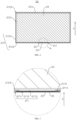
- FIG. 5 is a local enlarged view of Part A of the battery cell 20 shown in FIG. 4 .
- the present application provides a battery cell 20, where the battery cell 20 includes a housing 21, a pressure relief mechanism 22, and a protective member 23.
- the housing 21 is provided with a stepped hole 211 communicating with the inside of the housing 21, and the stepped hole 211 includes a first hole section 2111 and a second hole section 2112 provided in a first direction X, and the first hole section 2111 is located at one side of the second hole section 2112 away from the housing.
- the pressure relief mechanism 22 and the protective member 23 are provided in the second hole section 2112 and the first hole section 2111 respectively, and the protective member 23 covers at least part of the pressure relief mechanism 22.
- the battery cell 20 further includes an electrode assembly 24, and the housing 21 is used to accommodate the electrode assembly 24 thereinside.
- the housing 21 may also be used to accommodate an electrolyte, such as an electrolytic solution.
- the housing 21 may be in various structural forms.
- the material of the housing 21 may also be various, such as copper, iron, aluminum, steel, aluminum alloy, etc.
- the housing 21 includes a casing 212 and an end cover 213.
- An accommodation space 2121 for accommodating the electrode assembly 24 is formed inside the casing 212, and an opening 2122 is formed at one end of the casing 212.
- the opening 2122 communicates with the accommodation space 2121, i.e., the casing 212 is in a hollow structure with one end open, and the end cover 213 covers the opening 2122 of the casing 212 to form sealed connection, to form a sealed space used for accommodating the electrode assembly 24 and the electrolytic solution.
- the electrode assembly 24 When assembling the battery cell 20, the electrode assembly 24 may be placed inside the casing 212 first, electrolyte is filled into the casing 212, and then the end cover 213 covers the opening 2122 of the casing 212 to form sealed connection, to form a sealed space used for accommodating the electrode assembly 24 and the electrolyte.
- the end cover 213 is welded to the casing 212.
- the casing 212 may be in various shapes, such as a cylinder, a cuboid and so on.
- the shape of the casing 212 may be determined according to the specific shape of the electrode assembly 24. For example, if the electrode assembly 24 is in a cylindrical structure, a cylindrical structure may be selected; and if the electrode assembly 24 is in a cuboid structure, a cuboid structure may be selected. Exemplarily, in FIG. 3 , the electrode assembly 24 is in a cuboid structure, and the casing 212 is in a cuboid structure.
- the end cover 213 may be in various shapes, for example, the end cover 213 is in a plate-shaped structure or a hollow structure with one end open, and so on. Exemplarily, in FIG. 3 , the casing 212 is in a cuboid structure, the end cover 213 is in a plate-shaped structure, and the end cover 213 covers the opening 2122 of the casing 212.
- the stepped hole 211 may be provided on the casing 212, or may be provided on the end cover 213.
- the casing 212 has a bottom wall 2123 and a side wall 2124.
- the side wall 2124 is provided surrounding the peripheral wall of the bottom wall 2123, and one end of the peripheral wall is connected to the bottom wall 2123, and the other end thereof in the first direction X defines an opening 2122, and the stepped hole 211 is provided on the bottom wall 2123 of the casing 212, that is, the pressure relief mechanism 22 is installed on the bottom wall 2123 of the casing 212.
- the stepped hole 211 may also be provided on the side wall 2124 of the casing 212 or provided on the end cover 213.
- the stepped hole 211 includes a first hole section 2111 and a second hole section 2112 provided in the first direction X, and the first hole section 2111 is located at one side of the second hole section 2112 away from the housing, that is, the stepped hole 211 includes at least two hole sections, the first hole section 2111 and the second hole section 2112 respectively, and the second hole section 2112 is closer to the inside of 212 than the first hole section 2111.
- the first direction X is a direction from the outer surface of the casing 212 to the inside of the casing 212 in the thickness direction of the casing 212. Exemplarily, in FIG.
- the first direction X is a direction from the bottom wall 2123 of the casing 212 to the opening 2122 in the thickness direction of the bottom wall 2123.
- the stepped hole 211 has three hole sections.
- the three hole sections are the first hole section 2111, the second hole section 2112 and the third hole section 2113 which are arranged sequentially in the first direction X and whose hole diameters gradually decrease.
- the hole wall of the first hole section 2111 is connected to the outer surface of the casing 212.
- the pressure relief mechanism 22 is disposed in the second hole section 2112.
- the protective member 23 is disposed in the first hole section 2111, and the protective member 23 covers the second hole section 2111.
- the stepped hole 211 may also have two, four, five or six hole sections, etc.
- first hole section 2111, the second hole section 2112 and the third hole section 2113 may also be provided discontinuously, that is, other hole section(s) may be provided between the first hole section 2111 and the second hole section 2112 or between the second hole section 2112 and the third hole section 2113.
- the hole diameters of the first hole section 2111, the second hole section 2112, and the third hole section 2113 may also gradually increase in the first direction X.
- the pressure relief mechanism 22 is used for releasing the pressure inside the battery cell 20 when the internal pressure or temperature of the battery cell 20 reaches a predetermined value.
- the pressure relief mechanism 22 may be a component such as an explosion-proof valve, a bursting disc, a gas valve, a pressure relief valve, or a safety valve, etc.
- the pressure relief mechanism 22 may be in various shapes, such as elliptical shape, circular shape or rectangular shape.
- the pressure relief mechanism 22 is in an elliptical structure.
- the hole section of the stepped hole 211 is also in an elliptical structure.
- the long side of the pressure relief mechanism 22 in an elliptical structure extends in the width direction of the casing 212, that is, the length direction of the pressure relief mechanism 22 is the same as the width direction of the casing 212.
- the protective member 23 covers the side of the pressure relief mechanism 22 away from the electrode assembly 24 to protect the pressure relief mechanism 22, so as to reduce the risk of occurrence of wear or damage of the pressure relief mechanism 22 during use, thereby improving the use stability of the pressure relief mechanism. 22 to reduce the phenomenon that (the valve of) the pressure relief mechanism 22 is opened in advance.
- the protective member 23 may be made of various materials, such as plastic, rubber or silicone, etc.
- the battery cell 20 may further include a positive electrode terminal 25 and a negative electrode terminal 26.
- the positive electrode terminal 25 and the negative electrode terminal 26 are both installed on the end cover 213.
- the positive electrode terminal 25 and the negative electrode terminal 26 are both used to be electrically connected with the electrode assembly 24, to serve as the positive output electrode and the negative output electrode of the battery cell 20.
- the housing 21 is not only limited to the above structure.
- the housing 21 may also be in other structure.
- the housing 21 includes a casing 212 and two end covers 213, where the housing 212 is in a hollow structure with two opposite ends open, and one end cover 213 covers one end of the casing 212 correspondingly and forms sealed connection to form a sealed space used for accommodating the electrode assembly 24 and the electrolyte.
- the positive electrode terminal 25 and the negative electrode terminal 26 may be installed on the same end cover 213 or may be installed on different end covers 213.
- the electrode assembly 24 is a component, in the battery cell 20, where electrochemical reactions occur.
- the electrode assembly 24 may include a positive electrode plate, a negative electrode plate and a separator.
- the electrode assembly 24 may be in a winding structure formed by winding the positive electrode plate, the separator and the negative electrode plate, or may be in a stacked structure formed by stacking and arranging the positive electrode plate, the separator and the negative electrode plate.
- the housing 21 is provided with a stepped hole 211 used for allowing installing the pressure relief mechanism 22 and the protective member 23, and the protective member 23 and the pressure relief mechanism 22 are provided respectively in the first hole section 2111 and the second hole section 2112 of the stepped hole 211 which are provided in the first direction X, and the first hole section 2111 is located at one side of the second hole section 2112 away from the inside of the housing 21, so that the protective member 23 can cover at least part of the pressure relief mechanism 22 to protect the pressure relief mechanism 22.
- the battery cell 20 of this structure can reduce the phenomenon that the protective member 23 protrudes from the outer surface of the housing 21, which, on the one hand, can better protect the protective member 23 to reduce the risk of wear or damage of the protective member 23 during use, facilitating the protective member 23 protecting the pressure relief mechanism 22, further effectively prolonging the service life of the battery cell 20, and effectively improving the use stability and use safety of the battery cell 20, and on the other hand, can reduce the phenomenon that the protective member 23 increases the volume of the battery cell 20, facilitating saving the space occupied by battery cell 20.
- the hole diameter of the first hole section 2111 is larger than hole diameter of the second hole section 2112.
- the hole diameter of the first hole section 2111 is larger than the hole diameter of the second hole section 2112, that is, the stepped hole 211 is in a structure in which the hole diameter gradually decreases in the first direction X. That is, in the first direction X, the hole diameter of the hole section of the stepped hole 211 closest to the accommodation space 2121 of the casing 212 is the smallest.
- the hole diameters of the first hole section 2111, the second hole section 2112, and the third hole section 2113 gradually decrease.
- the stepped hole 211 is in a structure in which the hole diameter gradually decreases in the first direction X.
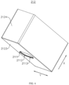
- FIG. 6 is a schematic structural view of a casing 212 of a battery cell 20 provided in some embodiments of the present application.
- the stepped hole 211 further includes a third hole section 2113.
- the first hole section 2111, the second hole section 2112 and the third hole section 2113 are arranged in the first direction X, and the hole diameter of the third hole section 2113 is smaller than the hole diameter of the second hole section 2112.
- the pressure relief mechanism 22 is provided in the second hole section 2112 and covers the third hole section 2113.
- the protective member 23 is provided in the first hole section 2111, and covers the second hole section 2112.
- the first hole section 2111, the second hole section 2112 and the third hole section 2113 are arranged in the first direction X, and the hole diameter of the third hole section 2113 is smaller than the hole diameter of the second hole section 2112. That is, the stepped hole 211 is provided with at least three hole sections, respectively the first hole section 2111, the second hole section 2112 and the third hole section 2113 which are arranged in the first direction X and whose hole diameters gradually decrease. Exemplarily, in FIG. 5 and FIG. 6 , the stepped hole 211 is provided with three hole sections. Of course, in other embodiments, the stepped hole 211 may also have four, five or six hole sections, etc.
- the first hole section 2111 may be the hole section farthest from the accommodation space 2121 of the casing 212 among the plurality of hole sections, or may be the hole section located in the middle region among the plurality of hole sections.
- the first hole section 2111, the second hole section 2112, and the third hole section 2113 may also be provided continuously or discontinuously, in the first direction X.
- the first hole section 2111, the second hole section 2112, and the third hole section 2113 are continuously provided in the first direction X.
- FIG. 7 is a sectional view of a casing 212 of a battery cell 20 provided in some embodiments of the present application; and FIG. 8 is a local enlarged view of Part B of the casing 212 shown in FIG. 7 .
- the housing 21 has a first connection surface 2114.
- the hole wall of the first hole section 2111 and the hole wall of the second hole section 2112 are connected through the first connection surface 2114.
- the protective member 23 abuts against the first connection surface 2114.
- the hole wall of the first hole section 2111 and the hole wall of the second hole section 2112 are connected through the first connection surface 2114. That is, the first connection surface 2114 is connected between the hole wall of the first hole section 2111 and the hole wall of the second hole section 2112, to form the shape of the step structure.
- the hole wall of the first hole section 2111 and the hole wall of the second hole section 2112 are both perpendicular to the first connection surface 2114, so that when the protective member 23 abuts against the first connection surface 2114, the contact area between the protection member 23 and the first connection surface 2114 can be effectively increased, to improve structural stability.
- the hole wall of the first hole section 2111 and the hole wall of the second hole section 2112 may also each be arranged at an obtuse angle or an acute angle with the first connection surface 2114.
- the housing 21 has a first connection surface 2114 used for connecting the hole wall of the first hole section 2111 and the hole wall of the second hole section 2112, so that the protective member 23 can abut against the first connection surface 2114 after being assembled into the first hole section 2111 of the stepped hole 211.
- a first connection surface 2114 used for connecting the hole wall of the first hole section 2111 and the hole wall of the second hole section 2112, so that the protective member 23 can abut against the first connection surface 2114 after being assembled into the first hole section 2111 of the stepped hole 211.
- the housing 21 further has a second connection surface 2115.
- the hole wall of the second hole section 2112 and the hole wall of the third hole section 2113 are connected through the second connection surface 2115.
- the pressure relief mechanism 22 abuts against the second connection surface 2115.
- the hole wall of the second hole section 2112 and the hole wall of the third hole section 2113 are connected through the second connection surface 2115. That is, the second connection surface 2115 is connected between the hole wall of the second hole section 2112 and the hole wall of the third hole section 2113, to form the shape of the step structure.
- the hole wall of the second hole section 2112 and the hole wall of the third hole section 2113 are both perpendicular to the second connection surface 2115, so that when the pressure relief mechanism 22 abuts against the second connection surface 2115, the contact area between the pressure relief mechanism 22 and the second connection surface 2115 can be effectively increased, to improve structural stability.
- the hole wall of the second hole section 2112 and the hole wall of the third hole section 2113 may also each be arranged at an obtuse angle or an acute angle with the second connection surface 2115.
- the housing 21 has a second connection surface 2115 used for connecting the hole wall of the second hole section 2112 and the hole wall of the third hole section 2113, so that the pressure relief mechanism 22 may abut against the second connection surface 2115 after being assembled into the second hole section 2112 of the stepped hole 211.
- a second connection surface 2115 used for connecting the hole wall of the second hole section 2112 and the hole wall of the third hole section 2113, so that the pressure relief mechanism 22 may abut against the second connection surface 2115 after being assembled into the second hole section 2112 of the stepped hole 211.
- the stepped hole 211 is provided with at least three hole sections, namely the first hole section 2111, the second hole section 2112 and the third hole section 2113 arranged in the first direction X.
- the pressure relief mechanism 22 is provided in the second hole section 2112 and covers the third hole section 2113, facilitating the pressure relief mechanism 22 releasing the internal pressure of the battery cell 20, and improving the assembly stability and reliability of assembling the pressure relief mechanism 22 into the stepped hole 211.
- the protective member 23 in the first hole section 2111 to cover the second hole section 2112, the protective member 23 can cover the pressure relief mechanism 22 as a whole, thereby better protecting the pressure relief mechanism 22.
- the depth of the first hole section 2111 is H 1 , satisfying: 0.2mm ⁇ H 1 ⁇ 0.6mm.
- the depth of the first hole section 2111 in the first direction X is the extension length of the first hole section 2111 in the first direction X, that is, the extension length of the first hole section 2111 in the first direction X is 0.2mm to 0.6mm.
- the stepped hole 211 is provided on the bottom wall 2123 of the casing 212, and the thickness of the bottom wall 2123 in the first direction X is 1 mm to 3 mm.
- the depth of the first hole section 2111 By setting the depth of the first hole section 2111 between 0.2mm and 0.6mm, on the one hand, it can alleviate the phenomenon of great difficulty in assembling the protective member 23 due to the too small depth of the first hole section 2111, and on the other hand, can alleviate the phenomenon of great difficulty in processing the first hole section 2111 due to the too large depth of the first hole section 2111, and can alleviate the phenomenon that more material needs to be squeezed and removed during the processing of the first hole section 2111 due to too large depth of the first hole section 2111, which results in that the outer surface of the housing 21 is partially bulged or partially squeezed to be extra wide during the processing of the first hole section 2111.
- FIG. 9 is a bottom view of a casing 212 provided in some embodiments of the present application.
- the cross-sectional area of the first hole section 2111 is S, where when 50mm 2 ⁇ S ⁇ 700mm 2 , 0.2mm ⁇ H 1 ⁇ 0.6mm; and when 700mm 2 ⁇ S ⁇ 1500mm 2 , 0.2mm ⁇ H 1 ⁇ 0.4mm.
- the cross-sectional area of the first hole section 2111 is S, that is, the area of the cross section of the first hole section 2111 perpendicular to the first direction X is S. That is, the area of a region formed by the projection of the first hole section 2111 on the outer surface of the casing 212 in the first direction X is S.
- the depth of the first hole section 2111 is set between 0.2mm and 0.6mm, and when the cross-sectional area of the first hole section 2111 is between 700mm 2 and 1500mm 2 , the depth of the first hole section 2111 is set between 0.2mm and 0.4mm.
- the depth of the first hole section 2111 needs to be set cooperatively in a different range to alleviate that more material needs to be squeezed and removed during the processing of the first hole section 2111 due to too large cross-sectional area of the first hole section 2111 and too large depth of the first hole section 2111, facilitating reducing the phenomenon that the outer surface of the housing 21 is partially bulged or partially squeezed to be extra wide during the processing of the first hole section 2111.
- the depth of the second hole section 2112 is H 2 , satisfying: 0.4mm ⁇ H 2 ⁇ 0.8mm.
- the depth of the second hole section 2112 in the first direction X is the extension length of the second hole section 2112 in the first direction X, that is, the extension length of the second hole section 2112 in the first direction X is 0.4mm to 0.8mm.
- the depth of the second hole section 2112 By setting the depth of the second hole section 2112 between 0.4mm and 0.8mm, on the one hand, it can alleviate the problems of great assembly difficulty of the pressure relief mechanism 22 and poor connection reliability of the pressure relief mechanism 22 due to the too small depth of the second hole section 2112, and on the other hand, can alleviate the phenomenon of increased processing difficulty of the second hole section 2112 due to the too large depth of the second hole section 2112.
- the depth of the third hole section 2113 is H 3 , satisfying: 0.3mm ⁇ H 3 ⁇ 2mm.
- the depth of the third hole section 2113 in the first direction X is the extension length of the third hole section 2113 in the first direction X, that is, the extension length of the third hole section 2113 in the first direction X is 0.3mm to 2mm.
- the depth of the third hole section 2113 By setting the depth of the third hole section 2113 between 0.3mm and 2mm, on the one hand, it can alleviate the phenomenon that due to the too small depth of the third hole section 2113, the structural strength of the region used for supporting and assembling the pressure relief mechanism 22 when the pressure relief mechanism 22 covers the third hole section 2113 is relatively weak, and on the other hand, can alleviate the phenomenon of increased processing difficulty of the third hole section 2113 due to the too large depth of the third hole section 2113.
- the electrode assembly and other components arranged inside the housing may be caused to squeeze/press the pressure relief mechanism 22, thereby causing damage to the pressure relief mechanism 22 and affecting its normal use. Therefore, the setting the depth of the third hole section 2113 between 0.3 mm and 2 mm can protect the pressure relief mechanism 22 and reduce the risk that the pressure relief mechanism 22 is damaged.
- the first hole section 2111, the second hole section 2112, and the third hole section 2113 are continuously provided in the first direction X.
- the first hole section 2111, the second hole section 2112 and the third hole section 2113 are continuously provided, that is, the first hole section 2111, the second hole section 2112 and the third hole section 2113 are arranged sequentially and continuously in the first direction X.
- the stepped hole 211 is provided with only the first hole section 2111, the second hole section 2112 and the third hole section 2113, that is, the stepped hole 211 includes three hole sections.
- the stepped hole 211 may include four, five, or six hole sections. When the stepped hole 211 has four or more hole sections, the other hole sections are located at one side of the third hole section 2113 away from the second hole section 2112 in the first direction X.
- the stepped hole 211 using this structure may also be provided with more hole sections on one side of the third hole section 2113 in the first direction X, which is conducive to further increasing the distance between the pressure relief mechanism 22 and the inner surface wall of the housing 21, to reduce the risk that the vibration conditions or expansion of the electrode assembly 24 of the battery cell 20 causes impact or pressing to the pressure relief mechanism 22.
- FIG. 10 is a sectional view of a casing 212 of a battery cell 20 provided in yet some embodiments of the present application; and FIG. 11 is a local enlarged view of Part C of the casing 212 shown in FIG. 10 .
- the stepped hole 211 further includes a fourth hole section 2116. In the first direction X, the fourth hole section 2116 is located between the first hole section 2111 and the second hole section 2112, and the hole diameter of the fourth hole section 2116 is smaller than the hole diameter of the first hole section 2111 and larger than the hole diameter of the second hole section 2112.
- the fourth hole section 2116 is located between the first hole section 2111 and the second hole section 2112.
- the hole diameter of the fourth hole section 2116 is smaller than the hole diameter of the first hole section 2111 and larger than the hole diameter of the second hole section 2112.
- the stepped hole 211 includes at least four hole sections, and the four hole sections are the first hole section 2111, the fourth hole section 2116, the second hole section 2112 and the third hole section 2113, which are arranged in sequence in the first direction X and whose hole diameters gradually decrease. That is, the protective member 23 provided in the first hole section 2111 and the pressure relief mechanism 22 provided in the second hole section 2112 are separated by the fourth hole section 2116.
- the first hole section 2111 and the second hole section 2112 are separated by the fourth hole section 2116, so as to increase the distance between the pressure relief mechanism 22 and the protective member 23, which further facilitates the pressure relief mechanism 22 releasing the pressure inside the battery cell 20 to ensure normal use of the pressure relief mechanism 22.
- the depth of the fourth hole section 2116 is H 4 , satisfying: 0.2mm ⁇ H 4 ⁇ 0.4mm.
- the depth of the fourth hole section 2116 in the first direction X is the extension length of the fourth hole section 2116 in the first direction X, that is, the extension length of the fourth hole section 2116 in the first direction X is 0.2mm to 0.4mm.
- the depth of the fourth hole section 2116 By setting the depth of the fourth hole section 2116 between 0.2mm and 0.4mm, on the one hand, it can alleviate the phenomenon that the distance between the pressure relief mechanism 22 and the protective member 23 is insufficient due to the too small depth of the fourth hole section 2116, to ensure the normal use of the pressure relief mechanism 22, and on the other hand, can alleviate the phenomenon that the space occupied by the fourth hole section 2116 is too large due to the too large depth of the fourth hole section 2116.
- the housing 21 has a wall portion, the stepped hole 211 is disposed on the wall portion, and first hole section 2111 penetrates through an outer surface of the wall portion.
- the housing 21 has a wall portion, that is, the wall portion is a wall of the housing 21.
- the wall portion may be the end cover 213 of the housing 21, or may be the bottom wall 2123 or the side wall 2124 of the casing 212.
- the wall portion is the bottom wall 2123 of the casing 212. That is, the stepped hole 211 is provided on the bottom wall 2123 of the casing 212.
- the first hole section 2111 penetrates through the outer surface of the wall portion, i.e., the hole wall of the first hole section 2111 is connected to the outer surface of the bottom wall 2123.That is, the first hole section 2111 is the hole section, among the multiple hole sections of the stepped hole 211, farthest from the accommodation space 2121 of the casing 212 in the first direction X.
- the housing 21 has a wall portion for being provided with the stepped hole 211, and the first hole section 2111 of the stepped hole 211 penetrates through the outer surface of the wall portion. That is, the first hole section 2111 is the hole section, among the multiple hole sections of the stepped hole 211, farthest from the inside of the housing 21, i.e., the hole wall of the first hole section 2111 is connected to the outer surface of the wall portion.
- Such structure facilitates assembling the protective member 23, which is conductive to reducing the assembly difficulty of assembling the protective member 23 into the first hole section 2111.
- the minimum distance from the hole wall of the first hole section 2111 to the edge of the wall portion is D 1 , which satisfies D 1 ⁇ 3mm.
- the minimum distance from the hole wall of the first hole section 2111 to the edge of the wall portion is the minimum distance between the hole wall of the first hole section 2111 and the edge of the bottom wall 2123.
- the battery cell 20 is in a cuboid structure, i.e., the casing 212 is in a cuboid structure, so that the bottom wall 2123 is in a rectangular structure.
- the minimum distance from the hole wall of the first hole section 2111 to the edge of the bottom wall 2123 is the distance between the hole wall of the first hole section 2111 and the closest side among the four sides of the bottom wall 2123 (closest side meaning that the distance between the side and the hole wall of the first hole section is smallest).
- the battery cell 20 may also be in a cylindrical structure, that is, the bottom wall 2123 is in a circular structure, and the minimum distance from the hole wall of the first hole section 2111 to the edge of the bottom wall 2123 is the minimum size from the hole wall of the first hole section 2111 to the outer edge of the bottom wall 2123 in the radial direction of the bottom wall 2123.
- the minimum distance between the hole wall of the first hole section 2111 and the edge of the wall portion can alleviate the phenomenon of great processing difficulty of the first hole section 2111 due to the too small distance between the hole wall of the first hole section 2111 and the edge of the wall portion, facilitating processing of the first hole section 2111 of the stepped hole 211.
- the minimum distance from the hole wall of the hole section adjacent to the first hole section 2111 to the edge of the wall portion is D 2 , which satisfies 0.5mm ⁇ D 2 -D 1 ⁇ 3mm.
- the minimum distance from the hole wall of the hole section adjacent to the first hole section 2111 to the edge of the wall portion is the minimum distance between the hole wall of the hole section adjacent to the first hole section 2111 and the edge of the bottom wall 2123.
- D 2 is the minimum distance from the hole wall of the second hole section 2112 to the edge of the bottom wall 2123 of the casing 212; and in the embodiment where the fourth hole section 2116 is provided between the first hole section 2111 and the second hole section 2112, D 2 is the minimum distance between the hole wall of the fourth hole section 2116 to the edge of the bottom wall 2123 of the casing 212.
- the bottom wall 2123 of the casing 212 is in a rectangular structure and the stepped hole 211 is in an elliptical shape, and the direction of the long side of the elliptical shape is consistent with the width direction Y of the bottom wall, and the width direction Y of the bottom wall and the first direction X are perpendicular to each other, so that the minimum distance D 1 from the hole wall of the first hole section 2111 to the edge of the wall portion is the minimum distance from the hole wall of the first hole section 2111 to the edge of the bottom wall 2123 in the width direction Y of the bottom wall, and that the minimum distance D 2 from the hole wall of the second hole section 2112 to the edge of the wall portion is the minimum distance from the hole wall of the second hole section 2112 to the edge of the bottom wall 2123 in the
- the cross-sectional area of the first hole section 2111 is S, where when 50mm 2 ⁇ S ⁇ 700mm 2 , 0.5mm ⁇ D 2 -D 1 ⁇ 3mm; and when 700mm 2 ⁇ S ⁇ 1500mm 2 , 0.5mm ⁇ D 2 -D 1 ⁇ 1.5mm.
- the cross-sectional area of the first hole section 2111 is S, i.e., the area of the cross section of the first hole section 2111 perpendicular to the first direction X is S, that is, the area of a region formed by the projection of the first hole section 2111 on the outer surface of the casing 212 in the first direction X is S.
- the difference between D 2 and D 1 is set between 0.5mm and 3mm, and when the cross-sectional area of the first hole section 2111 is between 700mm 2 and 1500mm 2 , the difference between D 2 and D 1 is set between 0.5mm and 1.5mm.
- the difference between D 2 and D 1 needs to be set cooperatively in a different range to alleviate that more material needs to be squeezed and removed during the processing of the first hole section 2111 due to too large cross-sectional area of the first hole section 2111 and too large difference between D 2 and D 1 , facilitating reducing the phenomenon that the outer surface of the wall portion is partially bulged or partially squeezed to be extra wide.
- the wall portion includes a first edge 2123a, a second edge 2123b, a third edge 2123c and a fourth edge 2123d connected in sequence, where the first edge 2123a and the third edge 2123c are provided oppositely in the width direction of the wall portion, the second edge 2123b and the fourth edge 2123d are provided oppositely in the length direction of the wall portion, and any two of the width direction of the wall portion, the length direction of the wall portion and the first direction X are perpendicular to each other.
- the minimum distance from the hole wall of the first hole section 2111 to the first edge 2123a is D 1
- the minimum distance from the hole wall of the second hole section 2112 to the first edge 2123a is D 2 .
- the wall portion is the bottom wall 2123 of the casing 212.
- the first edge 2123a and the third edge 2123c are arranged oppositely in the width direction of the wall portion, and the second edge 2123b and the fourth edge 2123d are arranged oppositely in the length direction of the wall portion, that is, the bottom wall 2123 is in a rectangular structure formed and enclosed by the first edge 2123a, the second edge 2123b, the third edge 2123c and the fourth edge 2123d.
- the width direction of the wall portion is the width direction Y of the bottom wall
- the length direction of the wall portion is the length direction Z of the bottom wall. Any two of the width direction Y of the bottom wall, the length direction Z of the bottom wall, and the first direction X are perpendicular to each other.
- the wall portion has a first edge 2123a, a second edge 2123b, a third edge 2123c and a fourth edge 2123d connected in sequence, with two of them arranged opposite to the other two, to form the wall portion in a rectangular structure, so that the minimum distances from the hole wall of the first hole section 2111 and the hole wall of the second hole section 2112 to the first edge 2123a of the wall portion in the width direction of the wall portion are D 1 and D 2 .
- the wall portion in this structure facilitates processing and manufacturing of the stepped hole 211 and ensuring the manufacturing accuracy of stepped hole 211.
- the housing 21 includes a casing 212 and an end cover 213.
- An accommodation space 2121 used for accommodating the electrode assembly 24 is formed inside the casing 212, one end of the casing 212 is provided with an opening 2122 communicating with the accommodation space 2121, the casing 212 has a wall portion, and the stepped hole 211 communicates with the accommodation space 2121.
- the end cover 213 covers the opening 2122.
- the casing 212 has a wall portion, the stepped hole 211 communicates with the accommodation space 2121. That is, the stepped hole 211 is provided on the casing 212 of the housing 21, and the stepped hole 211 penetrates through two sides of the casing 212. Certainly, in other embodiments, the stepped hole 211 may also be provided on provided on the end cover 213 of the housing 21.
- the stepped hole 211 is provided on the casing 212, so that the pressure relief mechanism 22 is installed on the casing 212.
- This structure facilitates the processing and manufacturing of the stepped hole 211, and is conductive to reducing the assembly difficulty between the pressure relief mechanism 22 and the casing 212.
- the casing 212 includes a bottom wall 2123 and a side wall 2124.
- the side wall 2124 is provided surrounding the bottom wall 2123, and one end of the side wall 2124 in the first direction X defines the opening 2122, and the other end opposite to the opening 2122 is connected to the bottom wall 2123.
- the wall portion is the bottom wall 2123.
- the wall portion is the bottom wall 2123, that is, the stepped hole 211 is provided on the bottom wall 2123 of the casing 212, and the stepped hole 211 penetrates through two sides of the bottom wall 2123 in the first direction X.
- the stepped hole 211 may also be provided on the side wall 2124 of the casing 212.
- the stepped hole 211 is provided on the bottom wall 2123 of the casing 212 to install the pressure relief mechanism 22 on the bottom wall 2123 of the casing 212.
- the battery 100 in this structure facilitates the battery cell 20 releasing the pressure inside the housing 21 through the pressure relief mechanism 22 during use.
- the phenomenon that the high-temperature gas released by the pressure relief mechanism 22 impacts the adjacent battery cells 20 can be alleviated by providing the pressure relief mechanism 22 on the bottom wall 2123 of the casing 212, to reduce the mutual influence between the battery cells 20, which is conductive to improving the use safety of the battery 100.
- the present application further provides a battery 100, including a plurality of battery cell 20 in any one of the above solutions.
- the battery 100 may further include a box body 10, and the plurality of battery cells 20 are accommodated in the box body 10.
- the present application further provides an electrical apparatus, including at least one battery 100 in any one of the above solutions, and the battery 100 is used to provide electric energy for the electrical apparatus.
- the electrical apparatus may be any aforementioned device or system using the battery 100.
- the present application provides a battery cell 20, where the battery cell 20 includes a housing 21, at least one electrode assembly 24, a pressure relief mechanism 22, and a protective member 23.
- the housing 21 includes a casing 212 and an end cover 213.
- the casing 212 includes a bottom wall 2123 and a side wall 2124.
- the side wall 2124 is provided surrounding the bottom wall 2123, and one end of the side wall 2124 in the first direction X defines the opening 2122, and the other end of the side wall opposite to the opening 2122 is connected to bottom wall 2123.
- the side wall 2124 and the bottom wall 2123 together define the accommodation space 2121 used for accommodating the at least one electrode assembly 24.
- the end cover 213 covers the opening 2122 of the casing 212.
- the bottom wall 2123 is provided with a stepped hole 211.
- the stepped hole 211 runs through two sides of the bottom wall 2123 in the first direction X.
- the stepped hole 211 includes a first hole section 2111, a second hole section 2112 and a third hole section 2113 whose hole diameters gradually decrease in the first direction X and which are provided continuously.
- the first hole section 2111 penetrates through the outer surface of the bottom wall 2123.
- the pressure relief mechanism 22 is provided in the second hole section 2112 and covers the third hole section 2113.
- the protective member 23 is provided in the first hole section 2111 and covers the second hole section 2112.
- the depth of the first hole section 2111 is H 1
- the depth of the second hole section 2112 is H 2
- the depth of the third hole section 2113 is H 3 , satisfying: 0.2mm ⁇ H 1 ⁇ 0.6mm, 0.4mm ⁇ H 2 ⁇ 0.8mm and 0.3mm ⁇ H 3 ⁇ 2mm.
- the minimum distance from the hole wall of the first hole section 2111 to the edge of the wall portion is D 1
- the minimum distance from the hole wall of the second hole section 2112 to the edge of the wall portion is D 2 , satisfying: D 1 ⁇ 3mm, and 0.5mm ⁇ D 2 -D 1 ⁇ 3mm.
Landscapes
- Chemical & Material Sciences (AREA)
- Chemical Kinetics & Catalysis (AREA)
- Electrochemistry (AREA)
- General Chemical & Material Sciences (AREA)
- Engineering & Computer Science (AREA)
- Manufacturing & Machinery (AREA)
- Sealing Battery Cases Or Jackets (AREA)
- Gas Exhaust Devices For Batteries (AREA)
- Battery Mounting, Suspending (AREA)
- Secondary Cells (AREA)
Abstract
Description
- The present application claims the priority to International Application
PCT/CN2022/078375 filed on February 28, 2022 - The present application relates to the technical field of batteries, and in particular, to a battery cell, a battery and an electrical apparatus.
- In recent years, new energy vehicles have developed by leaps and bounds. In the field of electric vehicles, power batteries, as the power source of the electric vehicles, play an irreplaceable and important role. With the vigorous promotion of new energy vehicles, the demand for power battery products is also increasing, wherein batteries, as the core components of new energy vehicles, have high requirements in terms of use safety. The battery cell of a battery is obtained by assembling a positive electrode plate, a negative electrode plate and a separator into an electrode assembly (bare cell) by means of winding or lamination, then placing it into a casing, covering the same with an end cover, and finally injecting an electrolytic solution, where a pressure relief component is provided on the casing or the end cover to release the internal pressure of the battery cell when the battery cell undergoes thermal runaway. However, the relief component of the battery cell in the prior art, when in use, has a problem of poor use stability, resulting in relatively poor use safety of the battery cell.
- Embodiments of the present application provide a battery cell, a battery and an electrical apparatus, which can effectively improve the use safety of the battery cell.
- In a first aspect, embodiments of the present application provide a battery cell, including a housing, a pressure relief mechanism and a protective member, where the housing is provided with a stepped hole communicating with the inside of the housing, and the stepped hole includes a first hole section and a second hole section provided in a first direction and the first hole section is located at one side of the second hole section away from the inside of the housing; and the pressure relief mechanism and the protective member are provided in the second hole section and the first hole section respectively, and the protective member covers at least part of the pressure relief mechanism.
- In the above technical solution, the housing is provided with a stepped hole for installing the pressure relief mechanism and the protective member, and the protective member and the pressure relief mechanism are provided respectively in the first hole section and the second hole section of the stepped hole which are provided in the first direction, and the first hole section is located at one side of the second hole section away from the inside of the housing, so that the protective member can cover at least part of the pressure relief mechanism to protect the pressure relief mechanism. The battery cell of this structure can reduce the phenomenon that the protective member protrudes from the outer surface of the housing, which, on the one hand, can better protect the protective member to reduce the risk of wear or damage of the protective member during use, facilitating the protective member protecting the pressure relief mechanism, further effectively prolonging the service life of the battery cell, and effectively improving the use stability and use safety of the battery cell, and on the other hand, can reduce the phenomenon that the protective member increases the volume of the battery cell, facilitating saving the space occupied by battery cell.
- In some embodiments, the hole diameter of the first hole section is larger than the hole diameter of the second hole section.
- In the above technical solution, by setting the hole diameter of the first hole section to be larger than the hole diameter of the second hole section, the stepped hole is in a structure in which the hole diameter gradually decreases in the first direction. For the battery cell using this structure, it is convenient to install the pressure relief mechanism in the second hole section from the outside of the housing during assembly process, and it is also convenient to install the protective member in the first hole section, facilitating reducing the assembly difficulty of the pressure relief mechanism and the protective member.
- In some embodiments, the stepped hole further includes a third hole section, where the first hole section, the second hole section and the third hole section are arranged in the first direction, the hole diameter of the third hole section is smaller than the hole diameter of the second hole section, the pressure relief mechanism is provided in the second hole section and covers the third hole section, and the protective member is provided in the first hole section, and covers the second hole section.
- In the above technical solution, the stepped hole is provided with at least three hole sections, that is, the first hole section, the second hole section and the third hole section arranged in the first direction. The pressure relief mechanism is provided in the second hole section and covers the third hole section, facilitating the pressure relief mechanism releasing the internal pressure of the battery cell, and improving the assembly stability and reliability of assembling the pressure relief mechanism into the stepped hole. In addition, by arranging the protective member in the first hole section to cover the second hole section, the protective member can cover the pressure relief mechanism as a whole, thereby better protecting the pressure relief mechanism.
- In some embodiments, in the first direction, the depth of the first hole section is H1, satisfying: 0.2mm≤H1≤0.6mm.
- In the above technical solution, by setting the depth of the first hole section between 0.2mm and 0.6mm, on the one hand, it can alleviate the phenomenon of great difficulty in assembling the protective member due to the too small depth of the first hole section, and on the other hand, It can alleviate the phenomenon of relatively high difficulty in processing the first hole section due to the too large depth of the first hole section, and can alleviate the phenomenon that more material needs to be squeezed and removed during the processing of the first hole section due to too large depth of the first hole section, which results in that the outer surface of the housing is partially bulged or partially squeezed to be extra wide during the processing of the first hole section.
- In some embodiments, the cross-sectional area of the first hole section is S, where when 50mm2≤S≤700mm2, 0.2mm≤H1≤0.6mm; and when 700mm2≤S≤1500mm2, 0.2mm≤H1≤0.4mm.
- In the above technical solution, when the cross-sectional area of the first hole section is between 50mm2 and 700mm2, the depth of the first hole section is set between 0.2mm and 0.6mm, and when the cross-sectional area of the first hole section is between 700mm2 and 1500mm2, the depth of the first hole section is set between 0.2mm and 0.4mm. That is, when the cross-sectional area of the first hole section is different, the depth of the first hole section needs to be cooperatively set in a different range to alleviate that more material needs to be squeezed and removed during the processing of the first hole section due to too large cross-sectional area of the first hole section and too large depth of the first hole section, facilitating reducing the phenomenon that the outer surface of the housing is partially bulged or partially squeezed to be extra wide during the processing of the first hole section.
- In some embodiments, in the first direction, the depth of the second hole section is H2, satisfying: 0.4mm≤ H2≤0.8mm.
- In the above technical solution, by setting the depth of the second hole section between 0.4mm and 0.8mm, on the one hand, it can alleviate the problem of relatively high assembly difficulty of the pressure relief mechanism and poor connection reliability of the pressure relief mechanism due to the too small depth of the second hole section, and on the other hand, can alleviate the phenomenon of increased processing difficulty of the second hole section due to the too large depth of the second hole section.
- In some embodiments, in the first direction, the depth of the third hole section is H3, satisfying: 0.3mm≤ H3≤2mm.
- In the above technical solution, by setting the depth of the third hole section between 0.3mm and 2mm, on the one hand, it can alleviate the phenomenon that due to the too small depth of the third hole section, the structural strength of the region used for supporting and assembling the pressure relief mechanism when the pressure relief mechanism covers the third hole section is relatively weak, and on the other hand, can alleviate the phenomenon of increased processing difficulty of the third hole section due to the too large depth of the third hole section.
- In some embodiments, the first hole section, the second hole section and the third hole section are continuously provided in the first direction.
- In the above technical solution, by arranging the first hole section, the second hole section and the third hole section continuously, it is conductive to further improving the manufacturability of the stepped hole, to reduce the processing difficulty of the stepped hole. In addition, the stepped hole using this structure may also be provided with more hole sections at one side of the third hole section in the first direction, which is conducive to further increasing the distance between the pressure relief mechanism and the inner surface wall of the housing, to reduce the risk that the vibration conditions or expansion of the electrode assembly of the battery cell causes impact or squeezing/pressing to the pressure relief mechanism.
- In some embodiments, the stepped hole further includes a fourth hole section; and in the first direction, the fourth hole section is located between the first hole section and the second hole section, and the hole diameter of the fourth hole section is smaller than the hole diameter of the first hole section and larger than the hole diameter of the second hole section.
- In the above technical solution, a fourth hole section is further provided between the first hole section and the second hole section in the first direction, so that the first hole section and the second hole section are separated by the fourth hole section, which is conducive to increasing the distance between the pressure relief mechanism and the protective member and further releasing the pressure inside the battery cell by the pressure relief mechanism, to ensure the normal use of the pressure relief mechanism.
- In some embodiments, in the first direction, the depth of the fourth hole section is H4, satisfying: 0.2mm≤ H4≤0.4mm.
- In the above solution, by setting the depth of the fourth hole section between 0.2mm and 0.4mm, on the one hand, it can alleviate the phenomenon that the distance between the pressure relief mechanism and the protective member is insufficient due to the too small depth of the fourth hole section, to ensure the normal use of the pressure relief mechanism, and on the other hand, can alleviate the phenomenon that the space occupied by the fourth hole section is too large due to the too large depth of the fourth hole section.
- In some embodiments, the housing has a wall portion, the stepped hole is disposed on the wall portion, and the first hole section penetrates through an outer surface of the wall portion.
- In the above technical solution, the housing has a wall portion for being provided with the stepped hole, and the first hole section of the stepped hole penetrates through the outer surface of the wall portion. That is to say, the first hole section is the hole section farthest from the inside of the housing in the hole sections of the stepped hole, i.e., the hole wall of the first hole section is connected to the outer surface of the wall portion. Such structure facilitates assembling the protective member, which is conductive to reducing the difficulty in assembling the protective member into the first hole section.
- In some embodiments, the minimum distance from the hole wall of the first hole section to the edge of the wall portion is D1, which satisfies D1≥3mm.
- In the above technical solution, by setting the minimum distance from the hole wall of the first hole section to the edge of the wall portion to be greater than or equal to 3 mm, it can alleviate the phenomenon of great processing difficulty of the first hole section due to the too small distance between the hole wall of the first hole section and the edge of the wall portion, facilitating processing of the first hole section of the stepped hole.
- In some embodiments, the minimum distance from the hole wall of the hole section adjacent to the first hole section to the edge of the wall portion is D2, which satisfies 0.5mm≤ D2-D1≤3mm.
- In the above technical solution, by setting the difference between the minimum distance between the hole wall of the hole section adjacent to the first hole section to the edge of the wall portion and the minimum distance between the hole wall of the first hole section to the edge of the wall portion between 0.5mm and 3mm, on the one hand, it can alleviate the phenomenon that due to the too small difference, the processing difficulty of the first hole section is great and it is not convenient to assemble the protective member, and on the other hand, it can alleviate that more material needs to be squeezed and removed during the processing of the first hole section due to too large difference, thus alleviating the phenomenon that the outer surface of the wall portion is partially bulged or partially squeezed to be extra wide during the processing of the first hole section.
- In some embodiments, the cross-sectional area of the first hole section is S, where when 50mm2≤S≤700mm2, 0.5mm≤D2-D1≤3mm; and when 700mm2≤S≤1500mm2, 0.5mm≤D2-D1≤1.5mm.
- In the above technical solution, when the cross-sectional area of the first hole section is between 50mm2 and 700mm2, the difference between D2 and D1 is set between 0.5mm and 3mm, and when the cross-sectional area of the first hole section is between 700mm2 and 1500mm2, the difference between D2 and D1 is set between 0.5mm and 1.5mm. That is, when the cross-sectional area of the first hole section is different, the difference between D2 and D1 needs to be set cooperatively in a different range to alleviate that more material needs to be squeezed and removed during the processing of the first hole section due to too large cross-sectional area of the first hole section and too large difference between D2 and D1, thus facilitating reducing the phenomenon that the outer surface of the wall portion is partially bulged or partially squeezed to be extra wide.
- In some embodiments, the wall portion includes a first edge, a second edge, a third edge and a fourth edge connected in sequence, where the first edge and the third edge are provided oppositely in the width direction of the wall portion, the second edge and the fourth edge are provided oppositely in the length direction of the wall portion, and any two of the width direction of the wall portion, the length direction of the wall portion and the first direction are perpendicular to each other; and the minimum distance from the hole wall of the first hole section to the first edge is D1, and the minimum distance from the hole wall of the hole section adjacent to the first hole section to the first edge is D2.
- In the above technical solution, the wall portion has a first edge, a second edge, a third edge and a fourth edge connected in sequence, with two of them arranged opposite to the other two, to form a wall portion in a rectangular structure, so that the minimum distances from the hole wall of the first hole section and the hole wall of the hole section adjacent to the first hole section to the first edge of the wall portion in the width direction of the wall portion are D1 and D2. The wall portion in this structure facilitates processing and manufacturing of the stepped hole and is conductive to ensuring the manufacturing accuracy of stepped hole.
- In some embodiments, the housing includes a casing and an end cover, where an accommodation space for accommodating an electrode assembly is formed inside the casing, one end of the casing is provided with an opening communicating with the accommodation space, the casing has the wall portion, and the stepped hole communicates with the accommodation space; and the end cover covers the opening.
- In the above technical solution, the casing of the housing has a wall portion, that is, the stepped hole is provided on the casing, so that the pressure relief mechanism is installed on the casing. This structure facilitates the processing and manufacturing of the stepped hole, and is conductive to reducing the assembly difficulty between the pressure relief mechanism and the casing.
- In some embodiments, the casing includes a bottom wall and a side wall; the side wall is provided surrounding the bottom wall, and one end of the side wall in the first direction define the opening, and the other end of the side wall opposite to the opening is connected to the bottom wall, wherein the wall portion is the bottom wall.
- In the above technical solution, the bottom wall of the casing is the wall portion, that is, the stepped hole is provided on the bottom wall of the casing, to allow installing the pressure relief mechanism on the bottom wall of the casing. The battery in this structure, on the one hand, facilitates the battery cell releasing the pressure inside the housing through the pressure relief mechanism during use. On the other hand, in the battery with such battery cells, when multiple battery cells are stacked into groups, the phenomenon that the high-temperature gas released by the pressure relief mechanism impacts the adjacent battery cells can be alleviated by providing the pressure relief mechanism on the bottom wall of the casing, to reduce the mutual influence between the battery cells, which is conductive to improving the use safety of the battery.
- In a second aspect, embodiments of the present application provide a battery, including a plurality of battery cells mentioned above.
- In a third aspect, embodiments of the present application provide an electrical apparatus, including at least one battery mentioned above.
- In order to more clearly illustrate the technical solutions of the embodiments of the present application, the drawings that are required to be used in the embodiments will be briefly introduced below. It should be understood that the following drawings only show some embodiments of the present application, and thus should not be regarded as a limitation on the scope, and those skilled in the art can also obtain other related drawings based on these drawings without paying creative work.
-
FIG. 1 is a schematic structural view of a vehicle provided in some embodiments of the present application; -
FIG. 2 is a structural exploded view of a battery provided in some embodiments of the present application; -
FIG. 3 is a structural exploded view of a battery cell provided in some embodiments of the present application; -
FIG. 4 is a sectional view of a battery cell provided in some embodiments of the present application; -
FIG. 5 is a local enlarged view of Part A of the battery cell shown inFIG. 4 ; -
FIG. 6 is a schematic structural view of a casing of a battery cell provided in some embodiments of the present application; -
FIG. 7 is a sectional view of a casing of a battery cell provided in some embodiments of the present application; -
FIG. 8 is a local enlarged view of Part B of the casing shown inFIG. 7 ; -
FIG. 9 is a bottom view of a casing provided in some embodiments of the present application; -
FIG. 10 is a sectional view of a casing of a battery cell provided in yet some embodiments of the present application; and -
FIG. 11 is a local enlarged view of Part C of the casing shown inFIG. 10 . - Reference signs: 1000-vehicle; 100-battery; 10-box body; 11-first box body; 12-second box body; 20-battery cell; 21-housing; 211-stepped hole; 2111-first hole section; 2112-second hole section; 2113-third hole section; 2114-first connection surface; 2115-second connection surface; 2116-fourth hole section; 212-casing; 2121-accommodation space; 2122-opening; 2123-bottom wall; 2123a-first edge; 2123b-second edge; 2123c-third edge; 2123d-fourth edge; 2124-side wall; 213-end cover; 22-pressure relief mechanism; 23-protective member; 24-electrode assembly; 25-positive electrode terminal; 26-negative electrode terminal; 200-controller; 300-motor; X-first direction; Y-width direction of bottom wall; Z-length direction of bottom wall.
- In order to make the purposes, technical solutions and advantages of the embodiments of the present application clearer, the technical solutions in the embodiments of the present application will be clearly described below in conjunction with the drawings in the embodiments of the present application. Obviously, the described embodiments are some, but not all of embodiments of the present application. Based on the embodiments in the present application, all other embodiments obtained by the person of ordinary skill in the art without paying creative efforts fall within the protection scope of the present application.
- Unless otherwise defined, all technical and scientific terms used in the present application have the same meaning as commonly understood by those skilled in the technical field of the present application. The terms used in the description of the present application are only for the purpose of describing embodiments, and are not intended to limit the present application. Terms "comprising" and "having" and any variations thereof in the specification and claims of the present application and the above description of the drawings are intended to cover a non-exclusive inclusion. The terms "first", "second" and the like in the description and claims of the present application or the above drawings are used to distinguish different objects, rather than to describe a specific sequence or primary-subordinate relationship.
- Reference made in the present application to "embodiment" means that a particular feature, structure, or characteristic described in connection with the embodiment may be included in at least one embodiment of the present application. The phases occurring in various places in the specification do not necessarily all refer to the same embodiment, nor separate or alternative embodiments mutually exclusive of other embodiments.
- In the description of this application, it should be noted that, unless otherwise clearly specified and defined, the terms "installation", "link", "connection" and "attachment" should be understood in a broad sense. For example, it may be fixed connection, it may also be detachable connection or integral connection; it may be direct connection or indirect connection through an intermediary, or it may be internal communication between two components. Those of ordinary skill in the art may understand the specific meanings of the above terms in the present application according to specific situations.
- The term "and/or" in the present application indicates only an association relationship describing associated objects, meaning that there may be three kinds of relationships. For example, A and/or B may indicate three situations: there is only A, there are both A and B, and there is only B. In addition, the character "/" in the present application generally indicates that the associated objects therebefore and thereafter have an "or" relationship.
- In the embodiments of the present application, the same reference signs represent the same components, and for the sake of brevity, in different embodiments, detailed descriptions of the same components are omitted. It should be understood that the thickness, length, width and other dimensions of the various components in the embodiments of the present application shown in the drawings, as well as the overall thickness, length, width and other dimensions of the integrated device, are for illustrative purposes only, and should not constitute any limitation to the present application.
- The term "multiple/a plurality of" appearing in the present application refers to more than two (including two).
- In the present application, the battery cell may include lithium ion secondary battery, lithium ion primary battery, lithium sulfur battery, sodium lithium ion battery, sodium ion battery or magnesium ion battery etc., which is not limited in the embodiments of the present application. The battery cell may be in a shape of cylinder, flat body, cuboid or in other shape, which is not limited in the embodiments of the present application. Battery cells are generally divided into three types according to packaging methods: cylindrical battery cells, square battery cells and pouch battery cells, which are also not limited in the embodiments of the present application.
- The battery mentioned in embodiments of the present application refers to a single physical module that includes one or more battery cells to provide higher voltage and capacity. For example, the battery mentioned in the present application may include a battery module or a battery pack, and the like. The battery generally includes a box body for packaging one or more battery cells or multiple battery modules. The box body may prevent a liquid or other foreign object from affecting the charging or discharging of the battery cells.
- The battery cell includes a housing, at least one electrode assembly and an electrolytic solution, wherein the housing is used to accommodate the at least one electrode assembly and the electrolytic solution. The electrode assembly is composed of a positive electrode plate, a negative electrode plate and a separator. The battery cell works mainly by moving metal ions between the positive electrode plate and negative electrode plate. The positive electrode plate includes a positive current collector and a positive electrode active material layer. The positive electrode active material layer is coated on the surface of the positive current collector, and the part of the positive current collector not coated with the positive electrode active material layer is used as the positive electrode tab, so that the input or output of the electrical energy of the positive electrode plate is achieved by the positive electrode tab. Taking a lithium-ion battery as an example, the material of the positive current collector may be aluminum, and the positive electrode active material may be lithium cobaltate, lithium iron phosphate, ternary lithium, or lithium manganate, etc. The negative electrode plate includes a negative current collector and a negative electrode active material layer. The negative electrode active material layer is coated on the surface of the negative current collector, and the part of the negative current collector not coated with the negative electrode active material layer is used as the negative electrode tab, so that the input or output of the electrical energy of the negative electrode plate is achieved by the negative electrode tab. The material of the negative current collector may be copper, and the negative electrode active material may be carbon or silicon, etc. In order to ensure that a large current passes without fusing, the number of positive electrode tabs is multiple and the positive electrode tabs are stacked together, and the number of negative electrode tabs is multiple and the negative electrode tabs are stacked together.
- The material of the separator may be PP (polypropylene) or PE (polyethylene), etc. In addition, the electrode assembly may be in a winding structure or may be in a laminated/stacked structure, which is not limited in the embodiments of the present application.
- Batteries, which have outstanding advantages such as high energy density, low environmental pollution, high power density, long service life, wide adaptation range, and small self-discharge coefficient, are important part of the development of new energy today. The battery cell of a battery is obtained by assembling a positive electrode plate, a negative electrode plate and a separator into an electrode assembly (bare cell) by means of winding or lamination, then placing it into a casing, covering the casing with an end cover, and finally injecting an electrolytic solution. However, with the continuous development of battery technology, higher requirements have been put forward for the safety performance of batteries.
- For ordinary battery cells, when the battery cells of the battery are short-circuited or overcharged, the internal gas pressure inside the battery cell may suddenly rise easily due to the internal thermal runaway, thus resulting in potential safety hazards such as battery fire and explosion. Therefore, a mounting hole is usually provided on the casing, and an explosion-proof valve is installed at the mounting hole, so that the internal gas pressure of the battery cell can break through the explosion-proof valve during the thermal runaway of the battery cell, to release the gas pressure inside the battery cell and reduce the risk of occurrence of fire and explosion of the battery cell.
- The inventors found that during the use of the battery cell, the explosion-proof valve will be affected by the external use environment to be worn or damaged, resulting in poor use stability and short service life of the explosion-proof valve. The above problems lead to the phenomenon that explosion-proof valve is often opened in advance, causing low use safety of the battery cells.
- In order to improve the use stability of the explosion-proof valve of the battery cell, in the prior art, a protective patch is usually provided at an outer side, where the explosion-proof valve is provided, of the casing of the battery cell, to better protect the explosion-proof valve. However, in the battery cell of this structure, since the protective patch protrudes from the outer side of the casing, on the one hand, there is a risk that the protective patch is worn or damaged by other components during use, resulting in that the protective patch cannot provide good protection for the explosion-proof valve, and that the service life of the battery cell is short, which is not conducive to improving the service life and use safety of the battery cell; and on the other hand, the protective patch may increase the volume of the battery cell, which is not conducive to saving the space occupied by battery cell.
- Based on the considerations above, in order to solve the problems of relatively short service life and poor use safety of the battery cell, the inventors designed a battery cell after in-depth researches, where the battery cell includes a housing, a pressure relief mechanism and a protective member. The housing is provided with a stepped hole communicating with the inside of the housing, and the stepped hole includes a first hole section and a second hole section provided in a first direction, and the first hole section is located at one side of the second hole section away from the inside of the housing. The pressure relief mechanism and the protective member are provided in the second hole section and the first hole section respectively, and the protective member covers at least part of the pressure relief mechanism.
- In the battery cell in this structure, the housing is provided with a stepped hole for installing the pressure relief mechanism and the protective member, and the protective member and the pressure relief mechanism are provided respectively in the first hole section and the second hole section of the stepped hole which are provided in the first direction, and the first hole section is located at one side of the second hole section away from the inside of the housing, so that the protective member can cover at least part of the pressure relief mechanism to protect the pressure relief mechanism. The battery cell of this structure can reduce the phenomenon that the protective member protrudes from the outer surface of the housing, which, on the one hand, can better protect the protective member to reduce the risk of occurrence of wear or damage of the protective member during use, facilitating the protective member protecting the pressure relief mechanism, further effectively prolonging the service life of the battery cell, and effectively improving the use stability and use safety of the battery cell, and on the other hand, can reduce the phenomenon that the protective member increases the volume of the battery cell, facilitating saving the space occupied by battery cell.
- The battery cell disclosed in the embodiments of the present application may be used in, but not limited to, electrical apparatus such as vehicles, ships or aircrafts. The power source system of the electrical apparatus may be composed using the battery cell and battery disclosed in the present application, which is conductive to improving the service life and use safety of the battery cell.
- Embodiments of the present application provide an electrical apparatus using the battery as a power source. The electrical apparatus may be, but not limited to, a mobile phone, a tablet, a notebook computer, an electric toy, an electric tool, a battery car, an electric vehicle, a ship, a spacecraft, and the like. Among them, the electric toy may include fixed or mobile electric toy, for example, game console, electric car toy, electric ship toy and electric airplane toy, etc., and the spacecraft may include airplane, rocket, space shuttle, spaceship, etc.
- In the following embodiments, for convenience of description, description is made by taking, as an example, an electrical apparatus according to an embodiment of the present application being a
vehicle 1000. - Referring to
FIG. 1, FIG. 1 is a schematic structural view of avehicle 1000 provided in some embodiments of the present application. Thevehicle 1000 may be a fuel vehicle, a gas vehicle or a new energy vehicle, and the new energy vehicle may be a pure electric vehicle, a hybrid power vehicle or an extended-range vehicle, etc. Abattery 100 is provided inside thevehicle 1000, and thebattery 100 may be provided at the bottom, head or tail of thevehicle 1000. Thebattery 100 may be used for supplying power to thevehicle 1000. For example, thebattery 100 may be used as an operating power source of thevehicle 1000. Thevehicle 1000 may further include acontroller 200 and amotor 300, thecontroller 200 being used to control thebattery 100 to supply power to themotor 300, for example, for working power requirements during starting, navigating and running of thevehicle 1000. - In some embodiments of the present application, the
battery 100 can not only be used as an operating power source for thevehicle 1000, but also be used as a driving power source for thevehicle 1000 to replace or partially replace fuel oil or natural gas to provide driving power for thevehicle 1000. - Referring to
FIG. 2, FIG. 2 is a structural exploded view of abattery 100 provided in some embodiments of the present application. Thebattery 100 include abox body 10 andbattery cells 20, and thebattery cells 20 are used to be accommodated in thebox body 10. In the above, thebox body 10 is used for providing an assembly space for thebattery cells 20, and thebox body 10 may be in various structures. In some embodiments, thebox body 10 may include a first box body 11 and asecond box body 12, the first box body 11 and thesecond box body 12 cover each other, and the first box body 11 and thesecond box body 12 together define an assembly space for accommodating thebattery cell 20. Thesecond box body 12 may be in a hollow structure with one end open, and the first box body 11 may be in a plate-shaped structure. The first box body 11 covers the open side of thesecond box body 12, so that the first box body 11 and the second box body 11 together define the assembly space; and the first box body 11 and thesecond box body 12 may also be both in a hollow structure with one side open, and the open side of the first box body 11 covers the open side of thesecond box body 12. Of course, thebox body 10 formed by the first box body 11 and thesecond box body 12 may be in various shapes, such as a cylinder, a cuboid and so on. - In the
battery 100, there may bemultiple battery cells 20, themultiple battery cells 20 may be in serial, parallel or hybrid connection with each other. The hybrid connection means that themultiple battery cells 20 are connected with each other both in series and in parallel. Themultiple battery cells 20 may be in serial, parallel or hybrid connection with each other directly, and then the whole composed of themultiple battery cells 20 is accommodated in thebox body 10. Certainly, thebattery 100 may be formed in the way that themultiple battery cells 20 are first in serial or in parallel or in hybrid connection with each other to form battery modules, and then the multiple battery modules are in serial or in parallel or in hybrid connection with each other to form a whole, and accommodated in thebox body 10. Thebattery 100 may also include other structures, for example, thebattery 100 may further include a bus component for realizing the electrical connection between themultiple battery cells 20. - In the above, each
battery cell 20 may be a secondary battery or a primary battery. It may also be a lithium-sulfur battery, a sodium-ion battery or a magnesium-ion battery, but is not limited thereto. Thebattery cell 20 may be in a shape of cylinder, flat body, cuboid or in other shape, etc. Exemplarily, inFIG. 2 , thebattery cell 20 is in a cuboid structure. - According to some embodiments of the present application, referring to
FIG.3 ,FIG. 4 and FIG. 5 ,FIG. 3 is a structural exploded view of abattery cell 20 provided in some embodiments of the present application;FIG. 4 is a sectional view of abattery cell 20 provided in some embodiments of the present application; andFIG. 5 is a local enlarged view of Part A of thebattery cell 20 shown inFIG. 4 . The present application provides abattery cell 20, where thebattery cell 20 includes ahousing 21, apressure relief mechanism 22, and aprotective member 23. Thehousing 21 is provided with a steppedhole 211 communicating with the inside of thehousing 21, and the steppedhole 211 includes afirst hole section 2111 and asecond hole section 2112 provided in a first direction X, and thefirst hole section 2111 is located at one side of thesecond hole section 2112 away from the housing. Thepressure relief mechanism 22 and theprotective member 23 are provided in thesecond hole section 2112 and thefirst hole section 2111 respectively, and theprotective member 23 covers at least part of thepressure relief mechanism 22. - The
battery cell 20 further includes anelectrode assembly 24, and thehousing 21 is used to accommodate theelectrode assembly 24 thereinside. Optionally, thehousing 21 may also be used to accommodate an electrolyte, such as an electrolytic solution. Thehousing 21 may be in various structural forms. The material of thehousing 21 may also be various, such as copper, iron, aluminum, steel, aluminum alloy, etc. - In
FIG. 3 , thehousing 21 includes acasing 212 and anend cover 213. Anaccommodation space 2121 for accommodating theelectrode assembly 24 is formed inside thecasing 212, and anopening 2122 is formed at one end of thecasing 212. Theopening 2122 communicates with theaccommodation space 2121, i.e., thecasing 212 is in a hollow structure with one end open, and theend cover 213 covers theopening 2122 of thecasing 212 to form sealed connection, to form a sealed space used for accommodating theelectrode assembly 24 and the electrolytic solution. - When assembling the
battery cell 20, theelectrode assembly 24 may be placed inside thecasing 212 first, electrolyte is filled into thecasing 212, and then theend cover 213 covers theopening 2122 of thecasing 212 to form sealed connection, to form a sealed space used for accommodating theelectrode assembly 24 and the electrolyte. Exemplarily, theend cover 213 is welded to thecasing 212. - The
casing 212 may be in various shapes, such as a cylinder, a cuboid and so on. The shape of thecasing 212 may be determined according to the specific shape of theelectrode assembly 24. For example, if theelectrode assembly 24 is in a cylindrical structure, a cylindrical structure may be selected; and if theelectrode assembly 24 is in a cuboid structure, a cuboid structure may be selected. Exemplarily, inFIG. 3 , theelectrode assembly 24 is in a cuboid structure, and thecasing 212 is in a cuboid structure. Of course, theend cover 213 may be in various shapes, for example, theend cover 213 is in a plate-shaped structure or a hollow structure with one end open, and so on. Exemplarily, inFIG. 3 , thecasing 212 is in a cuboid structure, theend cover 213 is in a plate-shaped structure, and theend cover 213 covers theopening 2122 of thecasing 212. - In the above, the stepped
hole 211 may be provided on thecasing 212, or may be provided on theend cover 213. Exemplarily, inFIG. 3 andFIG. 4 , thecasing 212 has abottom wall 2123 and aside wall 2124. Theside wall 2124 is provided surrounding the peripheral wall of thebottom wall 2123, and one end of the peripheral wall is connected to thebottom wall 2123, and the other end thereof in the first direction X defines anopening 2122, and the steppedhole 211 is provided on thebottom wall 2123 of thecasing 212, that is, thepressure relief mechanism 22 is installed on thebottom wall 2123 of thecasing 212. Certainly, in some embodiments, the steppedhole 211 may also be provided on theside wall 2124 of thecasing 212 or provided on theend cover 213. - The stepped
hole 211 includes afirst hole section 2111 and asecond hole section 2112 provided in the first direction X, and thefirst hole section 2111 is located at one side of thesecond hole section 2112 away from the housing, that is, the steppedhole 211 includes at least two hole sections, thefirst hole section 2111 and thesecond hole section 2112 respectively, and thesecond hole section 2112 is closer to the inside of 212 than thefirst hole section 2111. It should be noted that the first direction X is a direction from the outer surface of thecasing 212 to the inside of thecasing 212 in the thickness direction of thecasing 212. Exemplarily, inFIG. 3 , since the steppedhole 211 is provided on thebottom wall 2123 of thecasing 212, that is, the first direction X is a direction from thebottom wall 2123 of thecasing 212 to theopening 2122 in the thickness direction of thebottom wall 2123. - Exemplarily, in
FIG. 5 , the steppedhole 211 has three hole sections. For the convenience of description, the three hole sections are thefirst hole section 2111, thesecond hole section 2112 and thethird hole section 2113 which are arranged sequentially in the first direction X and whose hole diameters gradually decrease. The hole wall of thefirst hole section 2111 is connected to the outer surface of thecasing 212. Thepressure relief mechanism 22 is disposed in thesecond hole section 2112. Theprotective member 23 is disposed in thefirst hole section 2111, and theprotective member 23 covers thesecond hole section 2111. Of course, in other embodiments, the steppedhole 211 may also have two, four, five or six hole sections, etc. Similarly, thefirst hole section 2111, thesecond hole section 2112 and thethird hole section 2113 may also be provided discontinuously, that is, other hole section(s) may be provided between thefirst hole section 2111 and thesecond hole section 2112 or between thesecond hole section 2112 and thethird hole section 2113. Of course, in some embodiments, the hole diameters of thefirst hole section 2111, thesecond hole section 2112, and thethird hole section 2113 may also gradually increase in the first direction X. - It should be indicated that the
pressure relief mechanism 22 is used for releasing the pressure inside thebattery cell 20 when the internal pressure or temperature of thebattery cell 20 reaches a predetermined value. Exemplarily, thepressure relief mechanism 22 may be a component such as an explosion-proof valve, a bursting disc, a gas valve, a pressure relief valve, or a safety valve, etc. - The
pressure relief mechanism 22 may be in various shapes, such as elliptical shape, circular shape or rectangular shape. Exemplarily, inFIG. 3 , thepressure relief mechanism 22 is in an elliptical structure. Correspondingly, the hole section of the steppedhole 211 is also in an elliptical structure. In the above, the long side of thepressure relief mechanism 22 in an elliptical structure extends in the width direction of thecasing 212, that is, the length direction of thepressure relief mechanism 22 is the same as the width direction of thecasing 212. - The
protective member 23 covers the side of thepressure relief mechanism 22 away from theelectrode assembly 24 to protect thepressure relief mechanism 22, so as to reduce the risk of occurrence of wear or damage of thepressure relief mechanism 22 during use, thereby improving the use stability of the pressure relief mechanism. 22 to reduce the phenomenon that (the valve of) thepressure relief mechanism 22 is opened in advance. In the above, theprotective member 23 may be made of various materials, such as plastic, rubber or silicone, etc. - In some embodiments, the
battery cell 20 may further include apositive electrode terminal 25 and anegative electrode terminal 26. Thepositive electrode terminal 25 and thenegative electrode terminal 26 are both installed on theend cover 213. Thepositive electrode terminal 25 and thenegative electrode terminal 26 are both used to be electrically connected with theelectrode assembly 24, to serve as the positive output electrode and the negative output electrode of thebattery cell 20. - It can be understood that the
housing 21 is not only limited to the above structure. Thehousing 21 may also be in other structure. For example, thehousing 21 includes acasing 212 and two end covers 213, where thehousing 212 is in a hollow structure with two opposite ends open, and oneend cover 213 covers one end of thecasing 212 correspondingly and forms sealed connection to form a sealed space used for accommodating theelectrode assembly 24 and the electrolyte. In this structure, thepositive electrode terminal 25 and thenegative electrode terminal 26 may be installed on thesame end cover 213 or may be installed on different end covers 213. - The
electrode assembly 24 is a component, in thebattery cell 20, where electrochemical reactions occur. Theelectrode assembly 24 may include a positive electrode plate, a negative electrode plate and a separator. Theelectrode assembly 24 may be in a winding structure formed by winding the positive electrode plate, the separator and the negative electrode plate, or may be in a stacked structure formed by stacking and arranging the positive electrode plate, the separator and the negative electrode plate. - It should be noted that in the embodiments of the present application, there may be one or
more electrode assemblies 24 accommodated in thehousing 21. Exemplarily, inFIG. 3 , there are two electrode assemblies, and the two electrode assemblies are arranged in a stacked manner. - The
housing 21 is provided with a steppedhole 211 used for allowing installing thepressure relief mechanism 22 and theprotective member 23, and theprotective member 23 and thepressure relief mechanism 22 are provided respectively in thefirst hole section 2111 and thesecond hole section 2112 of the steppedhole 211 which are provided in the first direction X, and thefirst hole section 2111 is located at one side of thesecond hole section 2112 away from the inside of thehousing 21, so that theprotective member 23 can cover at least part of thepressure relief mechanism 22 to protect thepressure relief mechanism 22. Thebattery cell 20 of this structure can reduce the phenomenon that theprotective member 23 protrudes from the outer surface of thehousing 21, which, on the one hand, can better protect theprotective member 23 to reduce the risk of wear or damage of theprotective member 23 during use, facilitating theprotective member 23 protecting thepressure relief mechanism 22, further effectively prolonging the service life of thebattery cell 20, and effectively improving the use stability and use safety of thebattery cell 20, and on the other hand, can reduce the phenomenon that theprotective member 23 increases the volume of thebattery cell 20, facilitating saving the space occupied bybattery cell 20. - In some embodiments of the present application, referring to
FIG. 4 and FIG. 5 , the hole diameter of thefirst hole section 2111 is larger than hole diameter of thesecond hole section 2112. - In the above, the hole diameter of the
first hole section 2111 is larger than the hole diameter of thesecond hole section 2112, that is, the steppedhole 211 is in a structure in which the hole diameter gradually decreases in the first direction X. That is, in the first direction X, the hole diameter of the hole section of the steppedhole 211 closest to theaccommodation space 2121 of thecasing 212 is the smallest. Exemplarily, inFIG. 5 , in the first direction X, the hole diameters of thefirst hole section 2111, thesecond hole section 2112, and thethird hole section 2113 gradually decrease. - By setting the hole diameter of the
first hole section 2111 to be larger than the hole diameter of thesecond hole section 2112, the steppedhole 211 is in a structure in which the hole diameter gradually decreases in the first direction X. For thebattery cell 20 using this structure, it is convenient to install thepressure relief mechanism 22 in thesecond hole section 2112 from the outside of thehousing 21 during assembly process, and to install theprotective member 23 in thefirst hole section 2111, facilitating reducing the assembly difficulty of thepressure relief mechanism 22 and theprotective member 23. - According to some embodiments of the present application, referring to
FIG. 5 , and further referring toFIG. 6, FIG. 6 is a schematic structural view of acasing 212 of abattery cell 20 provided in some embodiments of the present application. The steppedhole 211 further includes athird hole section 2113. Thefirst hole section 2111, thesecond hole section 2112 and thethird hole section 2113 are arranged in the first direction X, and the hole diameter of thethird hole section 2113 is smaller than the hole diameter of thesecond hole section 2112. Thepressure relief mechanism 22 is provided in thesecond hole section 2112 and covers thethird hole section 2113. Theprotective member 23 is provided in thefirst hole section 2111, and covers thesecond hole section 2112. - In the above, the
first hole section 2111, thesecond hole section 2112 and thethird hole section 2113 are arranged in the first direction X, and the hole diameter of thethird hole section 2113 is smaller than the hole diameter of thesecond hole section 2112. That is, the steppedhole 211 is provided with at least three hole sections, respectively thefirst hole section 2111, thesecond hole section 2112 and thethird hole section 2113 which are arranged in the first direction X and whose hole diameters gradually decrease. Exemplarily, inFIG. 5 andFIG. 6 , the steppedhole 211 is provided with three hole sections. Of course, in other embodiments, the steppedhole 211 may also have four, five or six hole sections, etc. Of course, when the steppedhole 211 has four or more hole sections, thefirst hole section 2111 may be the hole section farthest from theaccommodation space 2121 of thecasing 212 among the plurality of hole sections, or may be the hole section located in the middle region among the plurality of hole sections. Similarly, thefirst hole section 2111, thesecond hole section 2112, and thethird hole section 2113 may also be provided continuously or discontinuously, in the first direction X. - Exemplarily, the
first hole section 2111, thesecond hole section 2112, and thethird hole section 2113 are continuously provided in the first direction X. - In some embodiments, referring to
FIG. 5 andFIG. 6 , and further referring toFIG. 7 and FIG. 8, FIG. 7 is a sectional view of acasing 212 of abattery cell 20 provided in some embodiments of the present application; andFIG. 8 is a local enlarged view of Part B of thecasing 212 shown inFIG. 7 . Thehousing 21 has afirst connection surface 2114. The hole wall of thefirst hole section 2111 and the hole wall of thesecond hole section 2112 are connected through thefirst connection surface 2114. Theprotective member 23 abuts against thefirst connection surface 2114. - In the above, the hole wall of the
first hole section 2111 and the hole wall of thesecond hole section 2112 are connected through thefirst connection surface 2114. That is, thefirst connection surface 2114 is connected between the hole wall of thefirst hole section 2111 and the hole wall of thesecond hole section 2112, to form the shape of the step structure. Exemplarily, inFIG. 8 , the hole wall of thefirst hole section 2111 and the hole wall of thesecond hole section 2112 are both perpendicular to thefirst connection surface 2114, so that when theprotective member 23 abuts against thefirst connection surface 2114, the contact area between theprotection member 23 and thefirst connection surface 2114 can be effectively increased, to improve structural stability. Of course, in other embodiments, the hole wall of thefirst hole section 2111 and the hole wall of thesecond hole section 2112 may also each be arranged at an obtuse angle or an acute angle with thefirst connection surface 2114. - The
housing 21 has afirst connection surface 2114 used for connecting the hole wall of thefirst hole section 2111 and the hole wall of thesecond hole section 2112, so that theprotective member 23 can abut against thefirst connection surface 2114 after being assembled into thefirst hole section 2111 of the steppedhole 211. For thehousing 21 of this structure, it is convenient to install theprotective member 23, and can effectively improve the assembly stability and reliability of providing theprotective member 23 in thefirst hole section 2111. - Optionally, the
housing 21 further has asecond connection surface 2115. The hole wall of thesecond hole section 2112 and the hole wall of thethird hole section 2113 are connected through thesecond connection surface 2115. Thepressure relief mechanism 22 abuts against thesecond connection surface 2115. - In the above, the hole wall of the
second hole section 2112 and the hole wall of thethird hole section 2113 are connected through thesecond connection surface 2115. That is, thesecond connection surface 2115 is connected between the hole wall of thesecond hole section 2112 and the hole wall of thethird hole section 2113, to form the shape of the step structure. Exemplarily, inFIG. 8 , the hole wall of thesecond hole section 2112 and the hole wall of thethird hole section 2113 are both perpendicular to thesecond connection surface 2115, so that when thepressure relief mechanism 22 abuts against thesecond connection surface 2115, the contact area between thepressure relief mechanism 22 and thesecond connection surface 2115 can be effectively increased, to improve structural stability. Of course, in other embodiments, the hole wall of thesecond hole section 2112 and the hole wall of thethird hole section 2113 may also each be arranged at an obtuse angle or an acute angle with thesecond connection surface 2115. - The
housing 21 has asecond connection surface 2115 used for connecting the hole wall of thesecond hole section 2112 and the hole wall of thethird hole section 2113, so that thepressure relief mechanism 22 may abut against thesecond connection surface 2115 after being assembled into thesecond hole section 2112 of the steppedhole 211. For thehousing 21 of this structure, it is convenient to install thepressure relief mechanism 22, and can improve the assembly stability and reliability of providing thepressure relief mechanism 22 in thesecond hole section 2112. - The stepped
hole 211 is provided with at least three hole sections, namely thefirst hole section 2111, thesecond hole section 2112 and thethird hole section 2113 arranged in the first direction X. Thepressure relief mechanism 22 is provided in thesecond hole section 2112 and covers thethird hole section 2113, facilitating thepressure relief mechanism 22 releasing the internal pressure of thebattery cell 20, and improving the assembly stability and reliability of assembling thepressure relief mechanism 22 into the steppedhole 211. In addition, by arranging theprotective member 23 in thefirst hole section 2111 to cover thesecond hole section 2112, theprotective member 23 can cover thepressure relief mechanism 22 as a whole, thereby better protecting thepressure relief mechanism 22. - According to some embodiments, referring to what is shown in
FIG. 8 , in the first direction X, the depth of thefirst hole section 2111 is H1, satisfying: 0.2mm≤H1≤0.6mm. - In the above, the depth of the
first hole section 2111 in the first direction X is the extension length of thefirst hole section 2111 in the first direction X, that is, the extension length of thefirst hole section 2111 in the first direction X is 0.2mm to 0.6mm. - Exemplarily, the stepped
hole 211 is provided on thebottom wall 2123 of thecasing 212, and the thickness of thebottom wall 2123 in the first direction X is 1 mm to 3 mm. - By setting the depth of the
first hole section 2111 between 0.2mm and 0.6mm, on the one hand, it can alleviate the phenomenon of great difficulty in assembling theprotective member 23 due to the too small depth of thefirst hole section 2111, and on the other hand, can alleviate the phenomenon of great difficulty in processing thefirst hole section 2111 due to the too large depth of thefirst hole section 2111, and can alleviate the phenomenon that more material needs to be squeezed and removed during the processing of thefirst hole section 2111 due to too large depth of thefirst hole section 2111, which results in that the outer surface of thehousing 21 is partially bulged or partially squeezed to be extra wide during the processing of thefirst hole section 2111. - According to some embodiments of the present application, referring to
FIG. 8 , and further referring toFIG. 9, FIG. 9 is a bottom view of acasing 212 provided in some embodiments of the present application. The cross-sectional area of thefirst hole section 2111 is S, where when 50mm2≤S≤700mm2, 0.2mm≤H1≤0.6mm; and when 700mm2≤S≤1500mm2, 0.2mm≤H1≤0.4mm. - In the above, the cross-sectional area of the
first hole section 2111 is S, that is, the area of the cross section of thefirst hole section 2111 perpendicular to the first direction X is S. That is, the area of a region formed by the projection of thefirst hole section 2111 on the outer surface of thecasing 212 in the first direction X is S. - When the cross-sectional area of the
first hole section 2111 is between 50mm2 and 700mm2, the depth of thefirst hole section 2111 is set between 0.2mm and 0.6mm, and when the cross-sectional area of thefirst hole section 2111 is between 700mm2 and 1500mm2, the depth of thefirst hole section 2111 is set between 0.2mm and 0.4mm. That is, when the cross-sectional area of thefirst hole section 2111 is different, the depth of thefirst hole section 2111 needs to be set cooperatively in a different range to alleviate that more material needs to be squeezed and removed during the processing of thefirst hole section 2111 due to too large cross-sectional area of thefirst hole section 2111 and too large depth of thefirst hole section 2111, facilitating reducing the phenomenon that the outer surface of thehousing 21 is partially bulged or partially squeezed to be extra wide during the processing of thefirst hole section 2111. - According to some embodiments, referring to what is shown in
FIG. 8 , in the first direction X, the depth of thesecond hole section 2112 is H2, satisfying: 0.4mm≤ H2≤0.8mm. - In the above, the depth of the
second hole section 2112 in the first direction X is the extension length of thesecond hole section 2112 in the first direction X, that is, the extension length of thesecond hole section 2112 in the first direction X is 0.4mm to 0.8mm. - By setting the depth of the
second hole section 2112 between 0.4mm and 0.8mm, on the one hand, it can alleviate the problems of great assembly difficulty of thepressure relief mechanism 22 and poor connection reliability of thepressure relief mechanism 22 due to the too small depth of thesecond hole section 2112, and on the other hand, can alleviate the phenomenon of increased processing difficulty of thesecond hole section 2112 due to the too large depth of thesecond hole section 2112. - According to some embodiments, continuing to refer to what is shown in
FIG. 8 , in the first direction X, the depth of thethird hole section 2113 is H3, satisfying: 0.3mm≤ H3≤2mm. - In the above, the depth of the
third hole section 2113 in the first direction X is the extension length of thethird hole section 2113 in the first direction X, that is, the extension length of thethird hole section 2113 in the first direction X is 0.3mm to 2mm. - By setting the depth of the
third hole section 2113 between 0.3mm and 2mm, on the one hand, it can alleviate the phenomenon that due to the too small depth of thethird hole section 2113, the structural strength of the region used for supporting and assembling thepressure relief mechanism 22 when thepressure relief mechanism 22 covers thethird hole section 2113 is relatively weak, and on the other hand, can alleviate the phenomenon of increased processing difficulty of thethird hole section 2113 due to the too large depth of thethird hole section 2113. In addition, if the depth of thethird hole section 2113 is too small, the electrode assembly and other components arranged inside the housing may be caused to squeeze/press thepressure relief mechanism 22, thereby causing damage to thepressure relief mechanism 22 and affecting its normal use. Therefore, the setting the depth of thethird hole section 2113 between 0.3 mm and 2 mm can protect thepressure relief mechanism 22 and reduce the risk that thepressure relief mechanism 22 is damaged. - According to some embodiments of the present application, referring to
FIG. 7 and FIG. 8 , thefirst hole section 2111, thesecond hole section 2112, and thethird hole section 2113 are continuously provided in the first direction X. - In the above, the
first hole section 2111, thesecond hole section 2112 and thethird hole section 2113 are continuously provided, that is, thefirst hole section 2111, thesecond hole section 2112 and thethird hole section 2113 are arranged sequentially and continuously in the first direction X. Exemplarily, inFIG. 8 , the steppedhole 211 is provided with only thefirst hole section 2111, thesecond hole section 2112 and thethird hole section 2113, that is, the steppedhole 211 includes three hole sections. Certainly, in some embodiments, the steppedhole 211 may include four, five, or six hole sections. When the steppedhole 211 has four or more hole sections, the other hole sections are located at one side of thethird hole section 2113 away from thesecond hole section 2112 in the first direction X. - By arranging the
first hole section 2111, thesecond hole section 2112 and thethird hole section 2113 continuously, it is conductive to further improving the manufacturability of the steppedhole 211, to reduce the processing difficulty of the steppedhole 211. In addition, the steppedhole 211 using this structure may also be provided with more hole sections on one side of thethird hole section 2113 in the first direction X, which is conducive to further increasing the distance between thepressure relief mechanism 22 and the inner surface wall of thehousing 21, to reduce the risk that the vibration conditions or expansion of theelectrode assembly 24 of thebattery cell 20 causes impact or pressing to thepressure relief mechanism 22. - According to some embodiments of the present application, referring to
FIG.10 andFIG. 11 ,FIG. 10 is a sectional view of acasing 212 of abattery cell 20 provided in yet some embodiments of the present application; andFIG. 11 is a local enlarged view of Part C of thecasing 212 shown inFIG. 10 . The steppedhole 211 further includes afourth hole section 2116. In the first direction X, thefourth hole section 2116 is located between thefirst hole section 2111 and thesecond hole section 2112, and the hole diameter of thefourth hole section 2116 is smaller than the hole diameter of thefirst hole section 2111 and larger than the hole diameter of thesecond hole section 2112. - In the above, in the first direction X, the
fourth hole section 2116 is located between thefirst hole section 2111 and thesecond hole section 2112. The hole diameter of thefourth hole section 2116 is smaller than the hole diameter of thefirst hole section 2111 and larger than the hole diameter of thesecond hole section 2112. That is, the steppedhole 211 includes at least four hole sections, and the four hole sections are thefirst hole section 2111, thefourth hole section 2116, thesecond hole section 2112 and thethird hole section 2113, which are arranged in sequence in the first direction X and whose hole diameters gradually decrease. That is, theprotective member 23 provided in thefirst hole section 2111 and thepressure relief mechanism 22 provided in thesecond hole section 2112 are separated by thefourth hole section 2116. - By further providing a
fourth hole section 2116 between thefirst hole section 2111 and thesecond hole section 2112 in the first direction X, thefirst hole section 2111 and thesecond hole section 2112 are separated by thefourth hole section 2116, so as to increase the distance between thepressure relief mechanism 22 and theprotective member 23, which further facilitates thepressure relief mechanism 22 releasing the pressure inside thebattery cell 20 to ensure normal use of thepressure relief mechanism 22. - In some embodiments, referring to what is shown in
FIG. 11 , in the first direction X, the depth of thefourth hole section 2116 is H4, satisfying: 0.2mm< H4≤0.4mm. - In the above, the depth of the
fourth hole section 2116 in the first direction X is the extension length of thefourth hole section 2116 in the first direction X, that is, the extension length of thefourth hole section 2116 in the first direction X is 0.2mm to 0.4mm. - By setting the depth of the
fourth hole section 2116 between 0.2mm and 0.4mm, on the one hand, it can alleviate the phenomenon that the distance between thepressure relief mechanism 22 and theprotective member 23 is insufficient due to the too small depth of thefourth hole section 2116, to ensure the normal use of thepressure relief mechanism 22, and on the other hand, can alleviate the phenomenon that the space occupied by thefourth hole section 2116 is too large due to the too large depth of thefourth hole section 2116. - According to some embodiments of the present application, referring to what is shown in
FIG. 6 ,FIG. 7 and FIG. 8 , thehousing 21 has a wall portion, the steppedhole 211 is disposed on the wall portion, andfirst hole section 2111 penetrates through an outer surface of the wall portion. - In the above, the
housing 21 has a wall portion, that is, the wall portion is a wall of thehousing 21. The wall portion may be theend cover 213 of thehousing 21, or may be thebottom wall 2123 or theside wall 2124 of thecasing 212. Exemplarily, inFIG. 6 andFIG. 9 , the wall portion is thebottom wall 2123 of thecasing 212. That is, the steppedhole 211 is provided on thebottom wall 2123 of thecasing 212. - The
first hole section 2111 penetrates through the outer surface of the wall portion, i.e., the hole wall of thefirst hole section 2111 is connected to the outer surface of the bottom wall 2123.That is, thefirst hole section 2111 is the hole section, among the multiple hole sections of the steppedhole 211, farthest from theaccommodation space 2121 of thecasing 212 in the first direction X. - The
housing 21 has a wall portion for being provided with the steppedhole 211, and thefirst hole section 2111 of the steppedhole 211 penetrates through the outer surface of the wall portion. That is, thefirst hole section 2111 is the hole section, among the multiple hole sections of the steppedhole 211, farthest from the inside of thehousing 21, i.e., the hole wall of thefirst hole section 2111 is connected to the outer surface of the wall portion. Such structure facilitates assembling theprotective member 23, which is conductive to reducing the assembly difficulty of assembling theprotective member 23 into thefirst hole section 2111. - According to some embodiments of the present application, referring to
FIG. 6 andFIG. 9 , the minimum distance from the hole wall of thefirst hole section 2111 to the edge of the wall portion is D1, which satisfies D1≥3mm. - In the above, the minimum distance from the hole wall of the
first hole section 2111 to the edge of the wall portion is the minimum distance between the hole wall of thefirst hole section 2111 and the edge of thebottom wall 2123. - Exemplarily, the
battery cell 20 is in a cuboid structure, i.e., thecasing 212 is in a cuboid structure, so that thebottom wall 2123 is in a rectangular structure. The minimum distance from the hole wall of thefirst hole section 2111 to the edge of thebottom wall 2123 is the distance between the hole wall of thefirst hole section 2111 and the closest side among the four sides of the bottom wall 2123 (closest side meaning that the distance between the side and the hole wall of the first hole section is smallest). Certainly, in other embodiments, thebattery cell 20 may also be in a cylindrical structure, that is, thebottom wall 2123 is in a circular structure, and the minimum distance from the hole wall of thefirst hole section 2111 to the edge of thebottom wall 2123 is the minimum size from the hole wall of thefirst hole section 2111 to the outer edge of thebottom wall 2123 in the radial direction of thebottom wall 2123. - By setting the minimum distance between the hole wall of the
first hole section 2111 and the edge of the wall portion to be greater than or equal to 3 mm, it can alleviate the phenomenon of great processing difficulty of thefirst hole section 2111 due to the too small distance between the hole wall of thefirst hole section 2111 and the edge of the wall portion, facilitating processing of thefirst hole section 2111 of the steppedhole 211. - According to some embodiments of the present application, referring to
FIG. 9 , the minimum distance from the hole wall of the hole section adjacent to thefirst hole section 2111 to the edge of the wall portion is D2, which satisfies 0.5mm≤D2-D1≤3mm. - In the above, the minimum distance from the hole wall of the hole section adjacent to the
first hole section 2111 to the edge of the wall portion is the minimum distance between the hole wall of the hole section adjacent to thefirst hole section 2111 and the edge of thebottom wall 2123. It should be noted that in an embodiment where thefirst hole section 2111, thesecond hole section 2112 and thethird hole section 2113 are continuously arranged in the first direction X, D2 is the minimum distance from the hole wall of thesecond hole section 2112 to the edge of thebottom wall 2123 of thecasing 212; and in the embodiment where thefourth hole section 2116 is provided between thefirst hole section 2111 and thesecond hole section 2112, D2 is the minimum distance between the hole wall of thefourth hole section 2116 to the edge of thebottom wall 2123 of thecasing 212. - Exemplarily, in
FIG. 9 , taking, as an example, the embodiment where the steppedhole 211 includes afirst hole section 2111, asecond hole section 2112 and athird hole section 2113 continuously provided in the first direction X, thebottom wall 2123 of thecasing 212 is in a rectangular structure and the steppedhole 211 is in an elliptical shape, and the direction of the long side of the elliptical shape is consistent with the width direction Y of the bottom wall, and the width direction Y of the bottom wall and the first direction X are perpendicular to each other, so that the minimum distance D1 from the hole wall of thefirst hole section 2111 to the edge of the wall portion is the minimum distance from the hole wall of thefirst hole section 2111 to the edge of thebottom wall 2123 in the width direction Y of the bottom wall, and that the minimum distance D2 from the hole wall of thesecond hole section 2112 to the edge of the wall portion is the minimum distance from the hole wall of thesecond hole section 2112 to the edge of thebottom wall 2123 in the width direction Y of the bottom wall. - By setting the difference between the minimum distance from the hole wall of the hole section adjacent to the
first hole section 2111 to the edge of the wall portion and the minimum distance from the hole wall of thefirst hole section 2111 to the edge of the wall portion between 0.5mm and 3mm, on the one hand, it can alleviate the phenomenon that due to the too small difference, the processing difficulty of thefirst hole section 2111 is great and it is not convenient to assemble theprotective member 23, and on the other hand, can alleviate that more material needs to be squeezed and removed during the processing of thefirst hole section 2111 due to too large difference, facilitating alleviating the phenomenon that the outer surface of the wall portion is partially bulged or partially squeezed to be extra wide during the processing of thefirst hole section 2111. - According to some embodiments of the present application, the cross-sectional area of the
first hole section 2111 is S, where when 50mm2≤S≤700mm2, 0.5mm≤D2-D1≤3mm; and when 700mm2≤S≤1500mm2, 0.5mm≤D2-D1≤1.5mm. - In the above, the cross-sectional area of the
first hole section 2111 is S, i.e., the area of the cross section of thefirst hole section 2111 perpendicular to the first direction X is S, that is, the area of a region formed by the projection of thefirst hole section 2111 on the outer surface of thecasing 212 in the first direction X is S. - When the cross-sectional area of the
first hole section 2111 is between 50mm2 and 700mm2, the difference between D2 and D1 is set between 0.5mm and 3mm, and when the cross-sectional area of thefirst hole section 2111 is between 700mm2 and 1500mm2, the difference between D2 and D1 is set between 0.5mm and 1.5mm. That is, when the cross-sectional area of thefirst hole section 2111 is different, the difference between D2 and D1 needs to be set cooperatively in a different range to alleviate that more material needs to be squeezed and removed during the processing of thefirst hole section 2111 due to too large cross-sectional area of thefirst hole section 2111 and too large difference between D2 and D1, facilitating reducing the phenomenon that the outer surface of the wall portion is partially bulged or partially squeezed to be extra wide. - In some embodiments, referring to what is shown in
FIG. 9 , the wall portion includes afirst edge 2123a, asecond edge 2123b, athird edge 2123c and afourth edge 2123d connected in sequence, where thefirst edge 2123a and thethird edge 2123c are provided oppositely in the width direction of the wall portion, thesecond edge 2123b and thefourth edge 2123d are provided oppositely in the length direction of the wall portion, and any two of the width direction of the wall portion, the length direction of the wall portion and the first direction X are perpendicular to each other. The minimum distance from the hole wall of thefirst hole section 2111 to thefirst edge 2123a is D1, and the minimum distance from the hole wall of thesecond hole section 2112 to thefirst edge 2123a is D2. - Exemplarily, the wall portion is the
bottom wall 2123 of thecasing 212. Thefirst edge 2123a and thethird edge 2123c are arranged oppositely in the width direction of the wall portion, and thesecond edge 2123b and thefourth edge 2123d are arranged oppositely in the length direction of the wall portion, that is, thebottom wall 2123 is in a rectangular structure formed and enclosed by thefirst edge 2123a, thesecond edge 2123b, thethird edge 2123c and thefourth edge 2123d. The width direction of the wall portion is the width direction Y of the bottom wall, and the length direction of the wall portion is the length direction Z of the bottom wall. Any two of the width direction Y of the bottom wall, the length direction Z of the bottom wall, and the first direction X are perpendicular to each other. - The wall portion has a
first edge 2123a, asecond edge 2123b, athird edge 2123c and afourth edge 2123d connected in sequence, with two of them arranged opposite to the other two, to form the wall portion in a rectangular structure, so that the minimum distances from the hole wall of thefirst hole section 2111 and the hole wall of thesecond hole section 2112 to thefirst edge 2123a of the wall portion in the width direction of the wall portion are D1 and D2. The wall portion in this structure facilitates processing and manufacturing of the steppedhole 211 and ensuring the manufacturing accuracy of steppedhole 211. - According to some embodiments of the present application, referring to
FIG. 3 andFIG. 4 , thehousing 21 includes acasing 212 and anend cover 213. Anaccommodation space 2121 used for accommodating theelectrode assembly 24 is formed inside thecasing 212, one end of thecasing 212 is provided with anopening 2122 communicating with theaccommodation space 2121, thecasing 212 has a wall portion, and the steppedhole 211 communicates with theaccommodation space 2121. Theend cover 213 covers theopening 2122. - In the above, the
casing 212 has a wall portion, the steppedhole 211 communicates with theaccommodation space 2121. That is, the steppedhole 211 is provided on thecasing 212 of thehousing 21, and the steppedhole 211 penetrates through two sides of thecasing 212. Certainly, in other embodiments, the steppedhole 211 may also be provided on provided on theend cover 213 of thehousing 21. - The stepped
hole 211 is provided on thecasing 212, so that thepressure relief mechanism 22 is installed on thecasing 212. This structure facilitates the processing and manufacturing of the steppedhole 211, and is conductive to reducing the assembly difficulty between thepressure relief mechanism 22 and thecasing 212. - According to some embodiments of the present application, referring to
FIG. 6 andFIG. 7 , thecasing 212 includes abottom wall 2123 and aside wall 2124. Theside wall 2124 is provided surrounding thebottom wall 2123, and one end of theside wall 2124 in the first direction X defines theopening 2122, and the other end opposite to theopening 2122 is connected to thebottom wall 2123. In the above, the wall portion is thebottom wall 2123. - The wall portion is the
bottom wall 2123, that is, the steppedhole 211 is provided on thebottom wall 2123 of thecasing 212, and the steppedhole 211 penetrates through two sides of thebottom wall 2123 in the first direction X. Certainly, in other embodiments, the steppedhole 211 may also be provided on theside wall 2124 of thecasing 212. - The stepped
hole 211 is provided on thebottom wall 2123 of thecasing 212 to install thepressure relief mechanism 22 on thebottom wall 2123 of thecasing 212. Thebattery 100 in this structure, on the one hand, facilitates thebattery cell 20 releasing the pressure inside thehousing 21 through thepressure relief mechanism 22 during use. On the other hand, in thebattery 100 withsuch battery cells 20, whenmultiple battery cells 20 are stacked into groups, the phenomenon that the high-temperature gas released by thepressure relief mechanism 22 impacts theadjacent battery cells 20 can be alleviated by providing thepressure relief mechanism 22 on thebottom wall 2123 of thecasing 212, to reduce the mutual influence between thebattery cells 20, which is conductive to improving the use safety of thebattery 100. - According to some embodiments of the present application, the present application further provides a
battery 100, including a plurality ofbattery cell 20 in any one of the above solutions. - In the above, referring to what is shown in
FIG. 2 , thebattery 100 may further include abox body 10, and the plurality ofbattery cells 20 are accommodated in thebox body 10. - According to some embodiments of the present application, the present application further provides an electrical apparatus, including at least one
battery 100 in any one of the above solutions, and thebattery 100 is used to provide electric energy for the electrical apparatus. - The electrical apparatus may be any aforementioned device or system using the
battery 100. - According to some embodiments of the present application, referring to what is shown in
FIG. 3 to FIG. 9 , the present application provides abattery cell 20, where thebattery cell 20 includes ahousing 21, at least oneelectrode assembly 24, apressure relief mechanism 22, and aprotective member 23. Thehousing 21 includes acasing 212 and anend cover 213. Thecasing 212 includes abottom wall 2123 and aside wall 2124. Theside wall 2124 is provided surrounding thebottom wall 2123, and one end of theside wall 2124 in the first direction X defines theopening 2122, and the other end of the side wall opposite to theopening 2122 is connected tobottom wall 2123. Theside wall 2124 and thebottom wall 2123 together define theaccommodation space 2121 used for accommodating the at least oneelectrode assembly 24. Theend cover 213 covers theopening 2122 of thecasing 212. Thebottom wall 2123 is provided with a steppedhole 211. The steppedhole 211 runs through two sides of thebottom wall 2123 in the first direction X. The steppedhole 211 includes afirst hole section 2111, asecond hole section 2112 and athird hole section 2113 whose hole diameters gradually decrease in the first direction X and which are provided continuously. Thefirst hole section 2111 penetrates through the outer surface of thebottom wall 2123. Thepressure relief mechanism 22 is provided in thesecond hole section 2112 and covers thethird hole section 2113. Theprotective member 23 is provided in thefirst hole section 2111 and covers thesecond hole section 2112. In the above, in the first direction X, the depth of thefirst hole section 2111 is H1, the depth of thesecond hole section 2112 is H2, and the depth of thethird hole section 2113 is H3, satisfying: 0.2mm≤H1≤0.6mm, 0.4mm≤H2≤0.8mm and 0.3mm≤H3≤2mm. The minimum distance from the hole wall of thefirst hole section 2111 to the edge of the wall portion is D1, and the minimum distance from the hole wall of thesecond hole section 2112 to the edge of the wall portion is D2, satisfying: D1≥3mm, and 0.5mm≤D2-D1≤3mm. - It should be noted that, without conflict, the embodiments in the present application and the features in the embodiments may be combined with each other.
- The above are only preferred embodiments of the present application, and are not intended to limit the present application. For those skilled in the art, there may be various modifications and changes in the present application. Any modifications, equivalent replacements, improvements, etc. made within the spirits and principles of the present application shall be included within the protection scope of the present application.
Claims (19)
- A battery cell, comprising:a housing, provided with a stepped hole communicating with an inside of the housing, wherein the stepped hole comprises a first hole section and a second hole section provided in a first direction, and the first hole section is located at one side of the second hole section away from the inside of the housing; anda pressure relief mechanism and a protective member, provided in the second hole section and the first hole section respectively, wherein the protective member covers at least part of the pressure relief mechanism.
- The battery cell according to claim 1, wherein a hole diameter of the first hole section is larger than a hole diameter of the second hole section.
- The battery according to claim 2, wherein the stepped hole further comprises:
a third hole section, wherein the first hole section, the second hole section and the third hole section are arranged in the first direction, a hole diameter of the third hole section is smaller than the hole diameter of the second hole section, the pressure relief mechanism is provided in the second hole section and covers the third hole section, and the protective member is provided in the first hole section and covers the second hole section. - The battery cell according to claim 3, wherein in the first direction, a depth of the first hole section is H1, satisfying: 0.2mm≤H1≤0.6mm.
- The battery cell according to claim 4, wherein a cross-sectional area of the first hole section is S, wherein when 50mm2≤S≤700mm2, 0.2mm≤H1≤0.6mm; and
when 700mm2≤S≤1500mm2, 0.2mm≤H1≤0.4mm. - The battery cell according to any one of claims 3 to 5, wherein in the first direction, a depth of the second hole section is H2, satisfying: 0.4mm≤H2≤0.8mm.
- The battery cell according to any one of claims 3 to 6, wherein in the first direction, a depth of the third hole section is H3, satisfying: 0.3mm≤H3≤2mm.
- The battery cell according to any one of claims 3 to 7, wherein the first hole section, the second hole section and the third hole section are continuously provided in the first direction.
- The battery cell according to any one of claims 3 to 7, wherein the stepped hole further comprises:
a fourth hole section, wherein in the first direction, the fourth hole section is located between the first hole section and the second hole section, and a hole diameter of the fourth hole section is smaller than the hole diameter of the first hole section and larger than the hole diameter of the second hole section. - The battery cell according to claim 9, wherein in the first direction, a depth of the fourth hole section is H4, satisfying: 0.2mm< H4≤0.4mm.
- The battery cell according to any one of claims 3 to 10, wherein the housing has a wall portion, the stepped hole is provided on the wall portion, and the first hole section penetrates through an outer surface of the wall portion.
- The battery cell according to claim 11, wherein a minimum distance from a hole wall of the first hole section to an edge of the wall portion is D1, which satisfies D1≥3mm.
- The battery cell according to claim 12, wherein a minimum distance from a hole wall of a hole section adjacent to the first hole section to the edge of the wall portion is D2, which satisfies: 0.5mm≤D2-D1≤3mm.
- The battery cell according to claim 13, wherein a cross-sectional area of the first hole section is S, wherein when 50mm2≤S≤700mm2, 0.5mm≤D2-D1≤3mm; and
when 700mm2≤S≤1500mm2, 0.5mm≤D2-D1≤1.5mm. - The battery cell according to claim 13 or 14, wherein the wall portion comprises a first edge, a second edge, a third edge and a fourth edge connected in sequence, wherein the first edge and the third edge are provided oppositely in a width direction of the wall portion, the second edge and the fourth edge are provided oppositely in a length direction of the wall portion, and any two of the width direction of the wall portion, the length direction of the wall portion and the first direction are perpendicular to each other; and
a minimum distance from the hole wall of the first hole section to the first edge is D1, and a minimum distance from the hole wall of the hole section adjacent to the first hole section to the first edge is D2. - The battery cell according to any one of claims 11 to 15, wherein the housing comprises:a casing, provided therein with an accommodation space configured for accommodating at least one electrode assembly, wherein one end of the casing is provided with an opening communicating with the accommodation space, the casing has the wall portion, and the stepped hole communicates with the accommodation space; andan end cover, covering the opening.
- The battery cell according to claim 16, wherein the casing comprises:a bottom wall; anda side wall, provided surrounding the bottom wall, wherein one end of the side wall in the first direction defines the opening, and the other end thereof opposite to the opening is connected to the bottom wall,wherein the wall portion is the bottom wall.
- A battery, comprising a plurality of battery cells each according to any one of claims 1 to 17.
- An electrical apparatus, comprising at least one battery each according to claim 18.
Applications Claiming Priority (2)
| Application Number | Priority Date | Filing Date | Title |
|---|---|---|---|
| PCT/CN2022/078375 WO2023159588A1 (en) | 2022-02-28 | 2022-02-28 | Battery cell, battery, and electrical device |
| PCT/CN2022/103094 WO2023159847A1 (en) | 2022-02-28 | 2022-06-30 | Battery cell, battery, and electrical apparatus |
Publications (2)
| Publication Number | Publication Date |
|---|---|
| EP4425674A1 true EP4425674A1 (en) | 2024-09-04 |
| EP4425674A4 EP4425674A4 (en) | 2025-05-21 |
Family
ID=84133333
Family Applications (3)
| Application Number | Title | Priority Date | Filing Date |
|---|---|---|---|
| EP22927869.2A Pending EP4379928A4 (en) | 2022-02-28 | 2022-02-28 | Battery cell, battery, and electrical device |
| EP22928110.0A Pending EP4418432A4 (en) | 2022-02-28 | 2022-06-30 | BATTERY CELL, BATTERY AND ELECTRICAL DEVICE |
| EP22928117.5A Pending EP4425674A4 (en) | 2022-02-28 | 2022-06-30 | BATTERY CELL, BATTERY AND ELECTRICAL DEVICE |
Family Applications Before (2)
| Application Number | Title | Priority Date | Filing Date |
|---|---|---|---|
| EP22927869.2A Pending EP4379928A4 (en) | 2022-02-28 | 2022-02-28 | Battery cell, battery, and electrical device |
| EP22928110.0A Pending EP4418432A4 (en) | 2022-02-28 | 2022-06-30 | BATTERY CELL, BATTERY AND ELECTRICAL DEVICE |
Country Status (6)
| Country | Link |
|---|---|
| US (3) | US20240250347A1 (en) |
| EP (3) | EP4379928A4 (en) |
| JP (2) | JP7799034B2 (en) |
| KR (1) | KR102951204B1 (en) |
| CN (5) | CN116982205A (en) |
| WO (3) | WO2023159588A1 (en) |
Families Citing this family (11)
| Publication number | Priority date | Publication date | Assignee | Title |
|---|---|---|---|---|
| CN119404361A (en) * | 2023-01-04 | 2025-02-07 | 宁德时代新能源科技股份有限公司 | Shell parts, battery cells, batteries and electrical equipment |
| WO2024152293A1 (en) * | 2023-01-19 | 2024-07-25 | 宁德时代新能源科技股份有限公司 | Battery cell, battery and electrical apparatus |
| CN118017144A (en) * | 2023-03-24 | 2024-05-10 | 宁德时代新能源科技股份有限公司 | Battery cells, batteries and electrical equipment |
| CN220121962U (en) * | 2023-04-18 | 2023-12-01 | 宁德时代新能源科技股份有限公司 | Battery cell, battery and electricity utilization device |
| CN116345057B (en) * | 2023-05-26 | 2023-09-22 | 宁德时代新能源科技股份有限公司 | Battery cells, batteries and electrical devices |
| CN116581466B (en) * | 2023-07-11 | 2023-10-27 | 宁德时代新能源科技股份有限公司 | Pressure release part, battery monomer, battery and power consumption device |
| EP4664645A4 (en) * | 2023-11-21 | 2026-03-25 | Contemporary Amperex Technology Co Ltd | BATTERY CELL, BATTERY AND ELECTRICAL DEVICE |
| CN117638254B (en) * | 2024-01-26 | 2024-04-26 | 宁德新能源科技有限公司 | Electrode assembly and battery |
| US20260005388A1 (en) * | 2024-06-26 | 2026-01-01 | GM Global Technology Operations LLC | Battery assembly including prismatic can battery cells having a side mounted vent cap |
| WO2026025389A1 (en) * | 2024-07-31 | 2026-02-05 | 宁德时代新能源科技股份有限公司 | Battery cell, battery, and electric device |
| EP4726865A1 (en) * | 2024-10-09 | 2026-04-15 | ABB Schweiz AG | Battery arrangement and method of manufacturing the battery arrangement |
Family Cites Families (23)
| Publication number | Priority date | Publication date | Assignee | Title |
|---|---|---|---|---|
| CN101685850A (en) * | 2008-09-26 | 2010-03-31 | 深圳市比克电池有限公司 | Lithium battery buffering explosion protection device and explosion protection lithium battery |
| KR20110003866A (en) * | 2009-07-06 | 2011-01-13 | 에스비리모티브 주식회사 | Lithium ion battery |
| KR101101093B1 (en) * | 2009-11-26 | 2012-01-03 | 삼성에스디아이 주식회사 | Case for secondary battery and lithium secondary battery using same |
| CN102136552B (en) * | 2010-01-27 | 2015-11-25 | 深圳市比克电池有限公司 | The manufacture method of battery protecting apparatus, battery and battery protecting apparatus |
| JP2014216304A (en) * | 2013-04-30 | 2014-11-17 | 栗田工業株式会社 | Gas absorption material for power storage device and power storage device including the same, and electrical apparatus and electronic apparatus including the power storage device |
| JP6299384B2 (en) * | 2014-04-24 | 2018-03-28 | 株式会社豊田自動織機 | Power storage device |
| JP6686286B2 (en) * | 2015-03-30 | 2020-04-22 | 三洋電機株式会社 | Prismatic secondary battery and assembled battery using the same |
| JP6816353B2 (en) * | 2015-10-26 | 2021-01-20 | 株式会社Gsユアサ | Power storage element |
| CN205657091U (en) * | 2016-05-16 | 2016-10-19 | 宁德时代新能源科技股份有限公司 | Secondary cell and casing thereof |
| CN206098459U (en) * | 2016-07-08 | 2017-04-12 | 宁德时代新能源科技股份有限公司 | Secondary battery and its battery case assembly |
| JP2018092726A (en) | 2016-11-30 | 2018-06-14 | 株式会社豊田自動織機 | Power storage device |
| JP6850208B2 (en) | 2017-06-19 | 2021-03-31 | 株式会社Gsユアサ | Power storage element and power storage module |
| CN108123084A (en) * | 2018-02-02 | 2018-06-05 | 华霆(合肥)动力技术有限公司 | Soft-package battery mounting structure and battery modules |
| CN112259937B (en) | 2019-07-05 | 2025-02-25 | 宁德时代新能源科技股份有限公司 | Battery Pack |
| CN111009679A (en) * | 2019-12-25 | 2020-04-14 | 天津荣盛盟固利新能源科技有限公司 | Three-electrode battery cell, three-electrode soft package battery and preparation method thereof |
| JP2021190360A (en) * | 2020-06-02 | 2021-12-13 | ブルースカイテクノロジー株式会社 | Lithium ion battery pack |
| WO2022006894A1 (en) | 2020-07-10 | 2022-01-13 | 宁德时代新能源科技股份有限公司 | Battery and related apparatus therefor, preparation method, and preparation device |
| CN213546446U (en) * | 2020-07-10 | 2021-06-25 | 宁德时代新能源科技股份有限公司 | Battery cell, battery and consumer |
| CN114175379B (en) | 2020-07-10 | 2023-11-28 | 宁德时代新能源科技股份有限公司 | Battery and related device, preparation method and preparation equipment thereof |
| CN212991189U (en) * | 2020-07-10 | 2021-04-16 | 宁德时代新能源科技股份有限公司 | Battery box, battery monomer, battery and consumer |
| EP3965219B1 (en) * | 2020-07-10 | 2023-06-07 | Contemporary Amperex Technology Co., Limited | Pressure relief mechanism, battery box, battery cell, battery, preparation method and device |
| CN112736363B (en) * | 2021-04-01 | 2021-07-20 | 江苏时代新能源科技有限公司 | Battery monomer, battery, electric device, method and equipment for preparing battery monomer |
| CN216250905U (en) * | 2021-09-10 | 2022-04-08 | 厦门海辰新能源科技有限公司 | Battery and electric equipment |
-
2022
- 2022-02-28 EP EP22927869.2A patent/EP4379928A4/en active Pending
- 2022-02-28 WO PCT/CN2022/078375 patent/WO2023159588A1/en not_active Ceased
- 2022-02-28 CN CN202280007965.6A patent/CN116982205A/en active Pending
- 2022-02-28 JP JP2024509011A patent/JP7799034B2/en active Active
- 2022-02-28 KR KR1020247004537A patent/KR102951204B1/en active Active
- 2022-06-30 CN CN202280022583.0A patent/CN117044023A/en active Pending
- 2022-06-30 CN CN202280016995.3A patent/CN116982207A/en active Pending
- 2022-06-30 CN CN202221669813.6U patent/CN217903284U/en active Active
- 2022-06-30 WO PCT/CN2022/102613 patent/WO2023159840A1/en not_active Ceased
- 2022-06-30 CN CN202221655744.3U patent/CN218274967U/en active Active
- 2022-06-30 WO PCT/CN2022/103094 patent/WO2023159847A1/en not_active Ceased
- 2022-06-30 EP EP22928110.0A patent/EP4418432A4/en active Pending
- 2022-06-30 EP EP22928117.5A patent/EP4425674A4/en active Pending
-
2024
- 2024-03-04 US US18/594,020 patent/US20240250347A1/en active Pending
- 2024-05-21 US US18/669,558 patent/US20240313339A1/en active Pending
- 2024-05-28 US US18/675,724 patent/US20240322351A1/en active Pending
-
2025
- 2025-12-25 JP JP2025281975A patent/JP2026062831A/en active Pending
Also Published As
| Publication number | Publication date |
|---|---|
| JP2026062831A (en) | 2026-04-10 |
| CN117044023A (en) | 2023-11-10 |
| CN116982205A (en) | 2023-10-31 |
| EP4425674A4 (en) | 2025-05-21 |
| US20240322351A1 (en) | 2024-09-26 |
| US20240250347A1 (en) | 2024-07-25 |
| CN217903284U (en) | 2022-11-25 |
| EP4379928A1 (en) | 2024-06-05 |
| EP4418432A4 (en) | 2025-07-30 |
| CN116982207A (en) | 2023-10-31 |
| WO2023159840A1 (en) | 2023-08-31 |
| US20240313339A1 (en) | 2024-09-19 |
| WO2023159588A1 (en) | 2023-08-31 |
| EP4418432A1 (en) | 2024-08-21 |
| KR20240032987A (en) | 2024-03-12 |
| WO2023159847A1 (en) | 2023-08-31 |
| JP7799034B2 (en) | 2026-01-14 |
| KR102951204B1 (en) | 2026-04-10 |
| CN218274967U (en) | 2023-01-10 |
| EP4379928A4 (en) | 2025-07-23 |
| JP2024531286A (en) | 2024-08-29 |
Similar Documents
| Publication | Publication Date | Title |
|---|---|---|
| EP4425674A1 (en) | Battery cell, battery, and electrical apparatus | |
| EP4439838A1 (en) | Battery cell, battery, and electric device | |
| EP4485660A1 (en) | Housing, battery cell, battery, and electrical device | |
| CN218867325U (en) | Battery cells, batteries, energy storage devices and electrical devices | |
| US11757161B2 (en) | Battery cell, battery and electricity consuming device | |
| EP4325644A1 (en) | End cap assembly, battery cell, battery, and electric apparatus | |
| CN218414926U (en) | Battery cells, batteries and electrical devices | |
| US20240363958A1 (en) | Pressure relief apparatus, housing, battery cell, battery, and electrical device | |
| US20250167382A1 (en) | Battery Cell, Battery, Energy Storage Apparatus and Electrical Apparatus | |
| CN216250906U (en) | Battery cell, battery and consumer | |
| US20240313303A1 (en) | Battery cell, battery, and electrical device | |
| US20230369711A1 (en) | End cap, battery cell, battery and power consuming device | |
| WO2025020499A1 (en) | Battery cell, battery pack, and electrical apparatus | |
| CN116470213A (en) | Battery modules, batteries and electrical devices | |
| CN116207436A (en) | Battery cell, manufacturing method and equipment thereof, battery and electricity utilization device | |
| WO2023028867A1 (en) | Shell, battery cell, battery, and electrical device | |
| US20250079651A1 (en) | Battery Cell, Battery and Electrical Equipment | |
| US20240055705A1 (en) | Battery cell, battery, power consuming apparatus, and method and apparatus for manufacturing battery cell | |
| US20250174779A1 (en) | Battery cell, battery and electricity-consuming device | |
| EP4376147A1 (en) | Battery, electric device, and method and device for preparing battery | |
| US20250079535A1 (en) | Electrode assembly, battery cell, battery, and electrical device | |
| US20240313337A1 (en) | End Cover, Battery Cell, Battery, and Electrical Device | |
| US12249723B2 (en) | Battery, electric device, and method and device for preparing battery cell | |
| CN219321476U (en) | End cover assembly, battery cell, battery and power utilization device | |
| EP4510256A1 (en) | Battery cell, battery, and electrical apparatus |
Legal Events
| Date | Code | Title | Description |
|---|---|---|---|
| STAA | Information on the status of an ep patent application or granted ep patent |
Free format text: STATUS: THE INTERNATIONAL PUBLICATION HAS BEEN MADE |
|
| PUAI | Public reference made under article 153(3) epc to a published international application that has entered the european phase |
Free format text: ORIGINAL CODE: 0009012 |
|
| STAA | Information on the status of an ep patent application or granted ep patent |
Free format text: STATUS: REQUEST FOR EXAMINATION WAS MADE |
|
| 17P | Request for examination filed |
Effective date: 20240531 |
|
| AK | Designated contracting states |
Kind code of ref document: A1 Designated state(s): AL AT BE BG CH CY CZ DE DK EE ES FI FR GB GR HR HU IE IS IT LI LT LU LV MC MK MT NL NO PL PT RO RS SE SI SK SM TR |
|
| RAP1 | Party data changed (applicant data changed or rights of an application transferred) |
Owner name: CONTEMPORARY AMPEREX TECHNOLOGY(HONG KONG) LIMITED |
|
| A4 | Supplementary search report drawn up and despatched |
Effective date: 20250416 |
|
| RIC1 | Information provided on ipc code assigned before grant |
Ipc: H01M 50/244 20210101ALI20250411BHEP Ipc: H01M 50/10 20210101ALI20250411BHEP Ipc: H01M 50/342 20210101AFI20250411BHEP |
|
| DAV | Request for validation of the european patent (deleted) | ||
| DAX | Request for extension of the european patent (deleted) |