EP4425652A2 - Verfahren zur herstellung einer sekundärbatterie und beutel für sekundärbatterie - Google Patents
Verfahren zur herstellung einer sekundärbatterie und beutel für sekundärbatterie Download PDFInfo
- Publication number
- EP4425652A2 EP4425652A2 EP24189635.6A EP24189635A EP4425652A2 EP 4425652 A2 EP4425652 A2 EP 4425652A2 EP 24189635 A EP24189635 A EP 24189635A EP 4425652 A2 EP4425652 A2 EP 4425652A2
- Authority
- EP
- European Patent Office
- Prior art keywords
- bridge
- pouch sheet
- accommodation grooves
- pouch
- right accommodation
- Prior art date
- Legal status (The legal status is an assumption and is not a legal conclusion. Google has not performed a legal analysis and makes no representation as to the accuracy of the status listed.)
- Pending
Links
Images


Classifications
-
- H—ELECTRICITY
- H01—ELECTRIC ELEMENTS
- H01M—PROCESSES OR MEANS, e.g. BATTERIES, FOR THE DIRECT CONVERSION OF CHEMICAL ENERGY INTO ELECTRICAL ENERGY
- H01M10/00—Secondary cells; Manufacture thereof
- H01M10/04—Construction or manufacture in general
- H01M10/0404—Machines for assembling batteries
-
- B—PERFORMING OPERATIONS; TRANSPORTING
- B29—WORKING OF PLASTICS; WORKING OF SUBSTANCES IN A PLASTIC STATE IN GENERAL
- B29C—SHAPING OR JOINING OF PLASTICS; SHAPING OF MATERIAL IN A PLASTIC STATE, NOT OTHERWISE PROVIDED FOR; AFTER-TREATMENT OF THE SHAPED PRODUCTS, e.g. REPAIRING
- B29C53/00—Shaping by bending, folding, twisting, straightening or flattening; Apparatus therefor
- B29C53/02—Bending or folding
- B29C53/04—Bending or folding of plates or sheets
-
- H—ELECTRICITY
- H01—ELECTRIC ELEMENTS
- H01M—PROCESSES OR MEANS, e.g. BATTERIES, FOR THE DIRECT CONVERSION OF CHEMICAL ENERGY INTO ELECTRICAL ENERGY
- H01M10/00—Secondary cells; Manufacture thereof
- H01M10/04—Construction or manufacture in general
- H01M10/0422—Cells or battery with cylindrical casing
-
- H—ELECTRICITY
- H01—ELECTRIC ELEMENTS
- H01M—PROCESSES OR MEANS, e.g. BATTERIES, FOR THE DIRECT CONVERSION OF CHEMICAL ENERGY INTO ELECTRICAL ENERGY
- H01M10/00—Secondary cells; Manufacture thereof
- H01M10/04—Construction or manufacture in general
- H01M10/0436—Small-sized flat cells or batteries for portable equipment
-
- H—ELECTRICITY
- H01—ELECTRIC ELEMENTS
- H01M—PROCESSES OR MEANS, e.g. BATTERIES, FOR THE DIRECT CONVERSION OF CHEMICAL ENERGY INTO ELECTRICAL ENERGY
- H01M10/00—Secondary cells; Manufacture thereof
- H01M10/04—Construction or manufacture in general
- H01M10/045—Cells or batteries with folded plate-like electrodes
-
- H—ELECTRICITY
- H01—ELECTRIC ELEMENTS
- H01M—PROCESSES OR MEANS, e.g. BATTERIES, FOR THE DIRECT CONVERSION OF CHEMICAL ENERGY INTO ELECTRICAL ENERGY
- H01M50/00—Constructional details or processes of manufacture of the non-active parts of electrochemical cells other than fuel cells, e.g. hybrid cells
- H01M50/10—Primary casings; Jackets or wrappings
- H01M50/102—Primary casings; Jackets or wrappings characterised by their shape or physical structure
- H01M50/105—Pouches or flexible bags
-
- H—ELECTRICITY
- H01—ELECTRIC ELEMENTS
- H01M—PROCESSES OR MEANS, e.g. BATTERIES, FOR THE DIRECT CONVERSION OF CHEMICAL ENERGY INTO ELECTRICAL ENERGY
- H01M50/00—Constructional details or processes of manufacture of the non-active parts of electrochemical cells other than fuel cells, e.g. hybrid cells
- H01M50/10—Primary casings; Jackets or wrappings
- H01M50/116—Primary casings; Jackets or wrappings characterised by the material
-
- H—ELECTRICITY
- H01—ELECTRIC ELEMENTS
- H01M—PROCESSES OR MEANS, e.g. BATTERIES, FOR THE DIRECT CONVERSION OF CHEMICAL ENERGY INTO ELECTRICAL ENERGY
- H01M50/00—Constructional details or processes of manufacture of the non-active parts of electrochemical cells other than fuel cells, e.g. hybrid cells
- H01M50/10—Primary casings; Jackets or wrappings
- H01M50/131—Primary casings; Jackets or wrappings characterised by physical properties, e.g. gas permeability, size or heat resistance
-
- H—ELECTRICITY
- H01—ELECTRIC ELEMENTS
- H01M—PROCESSES OR MEANS, e.g. BATTERIES, FOR THE DIRECT CONVERSION OF CHEMICAL ENERGY INTO ELECTRICAL ENERGY
- H01M50/00—Constructional details or processes of manufacture of the non-active parts of electrochemical cells other than fuel cells, e.g. hybrid cells
- H01M50/50—Current conducting connections for cells or batteries
- H01M50/543—Terminals
-
- B—PERFORMING OPERATIONS; TRANSPORTING
- B29—WORKING OF PLASTICS; WORKING OF SUBSTANCES IN A PLASTIC STATE IN GENERAL
- B29C—SHAPING OR JOINING OF PLASTICS; SHAPING OF MATERIAL IN A PLASTIC STATE, NOT OTHERWISE PROVIDED FOR; AFTER-TREATMENT OF THE SHAPED PRODUCTS, e.g. REPAIRING
- B29C51/00—Shaping by thermoforming, i.e. shaping sheets or sheet like preforms after heating, e.g. shaping sheets in matched moulds or by deep-drawing; Apparatus therefor
- B29C51/26—Component parts, details or accessories; Auxiliary operations
- B29C51/266—Auxiliary operations after the thermoforming operation
-
- B—PERFORMING OPERATIONS; TRANSPORTING
- B29—WORKING OF PLASTICS; WORKING OF SUBSTANCES IN A PLASTIC STATE IN GENERAL
- B29C—SHAPING OR JOINING OF PLASTICS; SHAPING OF MATERIAL IN A PLASTIC STATE, NOT OTHERWISE PROVIDED FOR; AFTER-TREATMENT OF THE SHAPED PRODUCTS, e.g. REPAIRING
- B29C53/00—Shaping by bending, folding, twisting, straightening or flattening; Apparatus therefor
- B29C53/36—Bending and joining, e.g. for making hollow articles
- B29C53/38—Bending and joining, e.g. for making hollow articles by bending sheets or strips at right angles to the longitudinal axis of the article being formed and joining the edges
-
- B—PERFORMING OPERATIONS; TRANSPORTING
- B29—WORKING OF PLASTICS; WORKING OF SUBSTANCES IN A PLASTIC STATE IN GENERAL
- B29L—INDEXING SCHEME ASSOCIATED WITH SUBCLASS B29C, RELATING TO PARTICULAR ARTICLES
- B29L2031/00—Other particular articles
- B29L2031/712—Containers; Packaging elements or accessories, Packages
- B29L2031/7146—Battery-cases
-
- H—ELECTRICITY
- H01—ELECTRIC ELEMENTS
- H01M—PROCESSES OR MEANS, e.g. BATTERIES, FOR THE DIRECT CONVERSION OF CHEMICAL ENERGY INTO ELECTRICAL ENERGY
- H01M10/00—Secondary cells; Manufacture thereof
- H01M10/04—Construction or manufacture in general
- H01M10/049—Processes for forming or storing electrodes in the battery container
-
- H—ELECTRICITY
- H01—ELECTRIC ELEMENTS
- H01M—PROCESSES OR MEANS, e.g. BATTERIES, FOR THE DIRECT CONVERSION OF CHEMICAL ENERGY INTO ELECTRICAL ENERGY
- H01M50/00—Constructional details or processes of manufacture of the non-active parts of electrochemical cells other than fuel cells, e.g. hybrid cells
- H01M50/10—Primary casings; Jackets or wrappings
- H01M50/116—Primary casings; Jackets or wrappings characterised by the material
- H01M50/117—Inorganic material
- H01M50/119—Metals
-
- H—ELECTRICITY
- H01—ELECTRIC ELEMENTS
- H01M—PROCESSES OR MEANS, e.g. BATTERIES, FOR THE DIRECT CONVERSION OF CHEMICAL ENERGY INTO ELECTRICAL ENERGY
- H01M50/00—Constructional details or processes of manufacture of the non-active parts of electrochemical cells other than fuel cells, e.g. hybrid cells
- H01M50/10—Primary casings; Jackets or wrappings
- H01M50/116—Primary casings; Jackets or wrappings characterised by the material
- H01M50/124—Primary casings; Jackets or wrappings characterised by the material having a layered structure
-
- H—ELECTRICITY
- H01—ELECTRIC ELEMENTS
- H01M—PROCESSES OR MEANS, e.g. BATTERIES, FOR THE DIRECT CONVERSION OF CHEMICAL ENERGY INTO ELECTRICAL ENERGY
- H01M50/00—Constructional details or processes of manufacture of the non-active parts of electrochemical cells other than fuel cells, e.g. hybrid cells
- H01M50/50—Current conducting connections for cells or batteries
- H01M50/531—Electrode connections inside a battery casing
- H01M50/54—Connection of several leads or tabs of plate-like electrode stacks, e.g. electrode pole straps or bridges
-
- Y—GENERAL TAGGING OF NEW TECHNOLOGICAL DEVELOPMENTS; GENERAL TAGGING OF CROSS-SECTIONAL TECHNOLOGIES SPANNING OVER SEVERAL SECTIONS OF THE IPC; TECHNICAL SUBJECTS COVERED BY FORMER USPC CROSS-REFERENCE ART COLLECTIONS [XRACs] AND DIGESTS
- Y02—TECHNOLOGIES OR APPLICATIONS FOR MITIGATION OR ADAPTATION AGAINST CLIMATE CHANGE
- Y02E—REDUCTION OF GREENHOUSE GAS [GHG] EMISSIONS, RELATED TO ENERGY GENERATION, TRANSMISSION OR DISTRIBUTION
- Y02E60/00—Enabling technologies; Technologies with a potential or indirect contribution to GHG emissions mitigation
- Y02E60/10—Energy storage using batteries
-
- Y—GENERAL TAGGING OF NEW TECHNOLOGICAL DEVELOPMENTS; GENERAL TAGGING OF CROSS-SECTIONAL TECHNOLOGIES SPANNING OVER SEVERAL SECTIONS OF THE IPC; TECHNICAL SUBJECTS COVERED BY FORMER USPC CROSS-REFERENCE ART COLLECTIONS [XRACs] AND DIGESTS
- Y02—TECHNOLOGIES OR APPLICATIONS FOR MITIGATION OR ADAPTATION AGAINST CLIMATE CHANGE
- Y02P—CLIMATE CHANGE MITIGATION TECHNOLOGIES IN THE PRODUCTION OR PROCESSING OF GOODS
- Y02P70/00—Climate change mitigation technologies in the production process for final industrial or consumer products
- Y02P70/50—Manufacturing or production processes characterised by the final manufactured product
Definitions
- the present invention relates to a method for manufacturing a secondary battery and a pouch for the secondary battery.
- Secondary batteries are rechargeable unlike primarily batteries, and also, the possibility of compact size and high capacity is high. Thus, recently, many studies on rechargeable batteries are being carried out. As technology development and demands for mobile devices increase, the demands for rechargeable batteries as energy sources are rapidly increasing.
- Rechargeable batteries are classified into coin type batteries, cylindrical type batteries, prismatic type batteries, and pouch type batteries according to a shape of a battery case.
- an electrode assembly mounted in a battery case is a chargeable and dischargeable power generating device having a structure in which an electrode and a separator are stacked.
- the electrode assembly may be approximately classified into a jelly-roll type electrode assembly in which a separator is interposed between a positive electrode and a negative electrode, each of which is provided as the form of a sheet coated with an active material, and then, the positive electrode, the separator, and the negative electrode are wound, a stacked type electrode assembly in which a plurality of positive and negative electrodes with a separator therebetween are sequentially stacked, and a stack/folding type electrode assembly in which stacked type unit cells are wound together with a separation film having a long length.
- the pouch-type battery in which a stack/folding type electrode assembly is built in a pouch-type battery case provided as an aluminum lamination sheet is attracting much attention due to its low manufacturing cost, small weight, easy shape deformation, and the like, and thus, its usage is gradually increasing.
- a wrinkle having a bat-ear shape may occur on the folded portion.
- One aspect of the present invention is to provide a method for manufacturing a secondary battery, through which capacity increases, and an occurrence of a winkle when a battery case is folded is prevented or significantly reduced, and a pouch for the secondary battery.
- a method for manufacturing a secondary battery a forming step of pressing a pouch sheet by using a press die so that left and right accommodation grooves, which are bilaterally symmetrical to each other and are opened upward, and a bridge connecting the left and right accommodation grooves to each other are formed in the pouch sheet to form a pouch sheet so that an electrode assembly is accommodated and a folding step of seating the electrode assembly on one of the left and right accommodation grooves to fold the electrode assembly so that the left and right accommodation grooves face each other, wherein, in the forming step, the pouch sheet is formed so that the bridge protrudes upward with respect to bottom surfaces of the left and right accommodation grooves, and a curved portion having a rounded shape is formed on an upper end of the bridge.
- a pouch for a secondary battery comprises left and right accommodation grooves in which an electrode assembly is accommodated and which are bilaterally symmetrical to each other and are opened upward and a bridge configured to connect the left and right accommodation grooves to each other, wherein the bridge protrudes upward with respect to bottom surfaces of the left and right accommodation grooves, and a curved portion having a rounded shape is formed on an upper end of the bridge.
- the battery case may be formed with the structure that is optimized to accommodate the electrode assembly and then be folded to increase in capacity and prevent the wrinkle such as the bat-ear shape from occurring or significantly reduce the occurrence of the wrinkle when the battery case is folded.
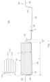
- FIG. 1 is a cross-sectional view illustrating a forming step in a method for manufacturing a secondary battery according to an embodiment of the present invention.
- a method for manufacturing a secondary battery comprises a forming step of forming left and right accommodation grooves 121 and 122 and a bridge on a pouch sheet 120 and a folding step of folding the pouch sheet 120 so that the left and right accommodation grooves 121 and 122 face each other.
- each of the bottom surfaces 128 and 129 of the left and right accommodation grooves 121 and 122 has an inclination that decreases at an angle of 1.5° to 3°.
- an occurrence of cracks due to pressing of the pouch 120 may be prevented.
- each of the bottom surfaces 128 and 129 of the left and right accommodation grooves 121 and 122 is formed to be equal to or greater than a lower limit value, the occurrence of the cracks due to a decrease in forming depth within the pouch 120 may be prevented.
- each of the left and right accommodation grooves 121 and 122 may have a width of 95 mm to 97 mm.
- each of the left and right accommodation grooves 121 and 122 may have a width of 96.7 mm.
- the electrode assembly 110 may be a chargeable and dischargeable power generation element and have a structure in which an electrode 113 and a separator 114 are combined and alternately stacked.
- the electrode 113 may comprise a positive electrode 111 and a negative electrode 112. Also, the separator 114 separates and electrically insulates the positive electrode 111 and the negative electrode 112 from each other.
- the positive electrode 111 may comprise a positive electrode collector (not shown) and a positive electrode active material (not shown) applied to the positive electrode collector
- the negative electrode 12 may comprise a negative electrode collector (not shown) and a negative electrode active material (not shown) applied to the negative electrode collector.
- the positive electrode collector may be provided as foil made of an aluminum (Al) material.
- the positive electrode active material may comprise, for example, lithium manganese oxide, lithium cobalt oxide, lithium nickel oxide, lithium iron phosphate, or a compound containing at least one of these and mixtures thereof.
- the negative electrode collector may be provided as foil made of a copper (Cu) or nickel (Ni) material.
- the negative electrode active material may comprise synthetic graphite, lithium a metal, a lithium alloy, carbon, petroleum coke, activated carbon, graphite, a silicon compound, a tin compound, a titanium compound, or an alloy thereof.
- the separator 114 is made of an insulation material and has a structure in which the positive electrode and the negative electrode are alternately stacked.
- the separator 114 may be disposed between the positive electrode and the negative electrode and outer surfaces of the positive electrode and the negative electrode.
- the separator 114 may be made of, for example, a polyolefin-based resin film such as polyethylene or polypropylene having micropores.
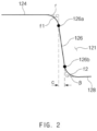
- FIG. 2 is a cross-sectional view illustrating a portion of the pouch sheet comprising an inflection surface in the method for manufacturing the secondary battery according to an embodiment of the present invention.
- a first bending part having a shape in which outer side surfaces of the left and right accommodation grooves 121 and 122 are respectively bent downward with respect to outer circumferential surfaces 124 and 125 of the pouch sheet 120 may have a first curved surface f1 having a rounded shape.
- the outer circumferential surfaces 124 and 125 of the pouch sheet 120 may mean, for example, surfaces disposed on outer edges of the pouch sheet 120.
- a second bending part having a shape in which outer side surfaces of the left and right accommodation grooves 121 and 122 are respectively bent upward with respect to the bottom surfaces 128 and 129 of the left and right accommodation grooves 121 and 122 may have a second curved surface f2 having a rounded shape.
- the pouch sheet 120 may be formed so that a clearance c of each of inflection surfaces 126 and 127 formed between the first curved surface f1 and the second curved surface f2 is maintained to be equal to or less than 0.5 mm.
- the pouch sheet 120 may be formed so that the clearance c of each of the inflection surfaces 126 and 127 formed between the first curved surface f1 and the second curved surface f2 is maintained to be equal to or less than 0.2 mm.
- the clearance c of each of the inflection surfaces 126 and 127 formed between the first curved surface f1 and the second curved surface f2 is formed to be equal to or less than an upper limit value, space efficiency may be optimized. That is, as the clearance c of each of the inflection surfaces 126 and 127 formed between the first curved surface f1 and the second curved surface f2 decreases, a volume of an empty space between the electrode assembly 110 and the pouch sheet 120, which have rectangular shapes, may decrease to improve the space efficiency.
- the pouch sheet 120 may be formed so that the inflection points 126 and 127 are formed as a plane.
- the inflection surface 126 may be a surface between a first inflection point 126a and a second inflection point 126b.
- the pouch sheet 120 may be formed so that each of an angle r between each of the outer circumferential surfaces 124 and 125 and each of the inflection surfaces 126 and 127 of the pouch sheet 120 and an angle ⁇ between each of the inflection surfaces 126 and 127 and each of the bottom surfaces 128 and 129 of the left and right accommodation grooves 121 and 122 is formed at an angle of 90° to 100°.
- the pouch sheet 120 may be formed so that each of the angle r between each of the outer circumferential surfaces 124 and 125 and each of the inflection surfaces 126 and 127 of the pouch sheet 120 and the angle ß between each of the inflection surfaces 126 and 127 and each of the bottom surfaces 128 and 129 of the left and right accommodation grooves 121 and 122 is formed at an angle of 93° to 98°.
- each of the angle r between each of the outer circumferential surfaces 124 and 125 and each of the inflection surfaces 126 and 127 of the pouch sheet 120 and the angle ⁇ between each of the inflection surfaces 126 and 127 and each of the bottom surfaces 128 and 129 of the left and right accommodation grooves 121 and 122 is formed to be equal to or less than an upper limit value, the clearance c of each of the inflection surfaces 126 and 127 formed between the first curved surface f1 and the second curved surface f2 may be narrowed.
- each of the angle r between each of the outer circumferential surfaces 124 and 125 and each of the inflection surfaces 126 and 127 of the pouch sheet 120 and the angle ⁇ between each of the inflection surfaces 126 and 127 and each of the bottom surfaces 128 and 129 of the left and right accommodation grooves 121 and 122 is formed to be equal to or greater than a lower limit value, machinability may be improved.
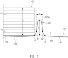
- FIG. 3 is a cross-sectional view illustrating a main part of the pouch sheet in the method for manufacturing the secondary battery according to an embodiment of the present invention
- FIG. 4 is a cross-sectional view illustrating a portion of the pouch sheet comprising a bridge in the method for manufacturing the secondary battery according to an embodiment of the present invention.
- the pouch sheet 120 may be formed so that the bridge 123 protrudes upward from the bottom surfaces 128 and 129 of the left and right accommodation parts 121 and 122, and a curved portion having a rounded shape is formed on an upper end 123a of the bridge 123.
- the pouch sheet 120 may be formed so that the upper end 123a of the bridge 123 has a semicircular shape.
- the bridge 123 may have a width W defined by a width of a protrusion protruding between the left and right accommodation grooves 121 and 122, and a reference point of the width of the protrusion may be defined by inflection points b1 and b2 between the bottom surfaces 128 and 129 of the left and right accommodation grooves 121 and 122 and the curved portion.
- the pouch sheet 120 may be formed so that the bridge 123 has a width W of 4 mm or less. Also, in the forming step, as a specific example, the pouch sheet 120 may be formed so that the bridge 123 has a width W of 2 mm or less.
- the width W of the bridge 123 is formed to be equal to or less than a lower limit value, an occurrence of a wrinkle having a bat-ear shape on the folded portion after the pouch sheet 120 is folded so that the left and right accommodation grooves 121 and 122 correspond to each other may be prevented or significantly reduced.
- the pouch sheet 120 may be formed to satisfy following conditional expression (1). h ⁇ d 1 + d 2 + d 3
- the side surface of the electrode assembly 110 may be completely surrounded. Also, if the conditional expression (1) is not satisfied, when the pouch sheet 120 is folded so that the left and right accommodation grooves 121 and 122 face each other, the left and right accommodation grooves 121 and 122 may not correspond to each other but be dislocated with respect to each other.
- the pouch sheet 120 may formed to satisfy following conditional expression (2). h/ 2 ⁇ a
- a phenomenon in which a wrinkle occurs at a remaining portion except for the portion that completely surrounds the side surface of the electrode assembly may be prevented. That is, a phenomenon in which the pouch sheet does not fully closely attached to the side surface of the electrode assembly 110 to cause the wrinkle after the folding when a portion of the pouch sheet 120, which faces the side surface of the electrode assembly 110, has a length that is significantly greater than that of the side surface of the electrode assembly 110 may be prevented or significantly reduced.
- FIG. 5 is a cross-sectional view illustrating the folding step in the method for manufacturing the rechargeable battery according to an embodiment of the present invention.
- the electrode assembly 110 may be seated on one of the left and right accommodation grooves 121 and 122, and then the pouch sheet 120 may be folded so the left and right accommodation grooves 121 and 122 face each other to manufacture the secondary battery 100.
- a sealing step of thermally fusing and sealing the outer circumferential surfaces 124 and 125 of the pouch sheet 120 may be further performed.
- the accommodation space in which the electrode assembly 110 is accommodated may be sealed to be blocked from the outside.
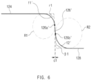
- FIG. 6 is a cross-sectional view illustrating an example of the forming step in the method for manufacturing the secondary battery according to an embodiment of the present invention
- FIG. 7 is a cross-sectional view illustrating another example of the forming step in the method for manufacturing the secondary battery according to an embodiment of the present invention.
- the first curved surface f1' may be formed as a portion of a circle having a radius R1
- the second curved surface f2' may be formed as a portion of a circle having a radius R2.
- the radius R1 is 1.5 mm
- the radius R2 is 2 mm.
- the pouch sheet 120 may be formed so that a clearance c2 of an inflection surface 126" formed between a first curved surface f1" and a second curved surface f2" is 0.25 mm.
- the pouch sheet 120 may be formed so that each of an angle r2 between each of the outer circumferential surfaces 124 and 125 and the inflection surface 126" of the pouch sheet 120 and an angle ⁇ 2 between the inflection surface 126" and each of the bottom surfaces 128 and 129 of the left and right accommodation grooves 121 and 122 is formed at an angle of 96.1°.
- first curved surface f1" may be formed as a portion of a circle having a radius R1
- second curved surface f2" may be formed as a portion of a circle having a radius R2.
- the radius R1 is 1.5 mm
- the radius R2 is 2 mm.
- the pouch sheet When left and right accommodation grooves 121 and 122 that are bilaterally symmetrical to each other are formed in a pouch sheet, the pouch sheet was formed so that each of bottom surfaces 128 and 129 of the left and right accommodation grooves 121 and 122 is inclined. Also, a bridge had a width W of 4.0 mm, a clearance c of an inflection surface formed between a first curved surface f1 and a second curved surface f2 was 0.5 mm, and then, a secondary battery was manufactured (see FIGS. 1 to 3 ).
- the pouch sheet when left and right accommodation grooves 121 and 122 that are bilaterally symmetrical to each other are formed in a pouch sheet, the pouch sheet was formed so that each of bottom surfaces 128 and 129 of the left and right accommodation grooves 121 and 122 is inclined. Also, a bridge had a width W of 2.0 mm, a clearance c of an inflection surface formed between a first curved surface f1 and a second curved surface f2 was 0.35 mm, and then, a secondary battery was manufactured (see FIGS. 1 to 3 ).
- the pouch sheet When left and right accommodation grooves 121 and 122 that are bilaterally symmetrical to each other are formed in a pouch sheet, the pouch sheet was formed so that each of bottom surfaces of the left and right accommodation grooves is not inclined but horizontally flat. Also, a bridge had a width W of 5.0 mm, a clearance c of an inflection surface formed between a first curved surface f1 and a second curved surface f2 was 1.0 mm, and then, a secondary battery was manufactured.
- Embodiment 1 Embodiment 2 Comparative Example 1 Formed shape of bottom surface of accommodation groove (existence and nonexistence of inclination of bottom surface) Inclination formation (inclination of bottom surface O) Inclination formation (inclination of bottom surface O) Planar surface formation (inclination of bottom surface X) Width W of bridge (W) 4.0mm 2.0mm 5.0mm Clearance c of inflection surface formed between first curved surface f1 and second curved surface f2 0.5mm 0.35mm 1.0mm Size of wrinkle at folded portion (Bat-ear size) 3.4mm 2mm or less 4.5mm or more
- a wrinkle having a bat-ear shape has a size of 4.5 mm or more.
- a wrinkle having a bat-ear shape has a size of 3.4 mm
- a wrinkle having a bat-ear shape has a size of 2 mm or less.
- the wrinkle at the folded portion is significantly reduced to significantly reduce damage of an outer appearance and an occurrence of cracks in comparison with Comparative Example 1 of the manufacturing method according to the related art.
- a pouch for a secondary battery according to an embodiment of the present invention will be described.
- a pouch 120 for a secondary battery comprises left and right accommodation grooves 121 and 122, which accommodate an electrode assembly, are bilaterally symmetrical to each other, and are opened upward, and a bridge 123 connecting the left and right accommodation grooves 121 and 122 to each other.
- the pouch for the secondary battery according to an embodiment of the present invention relates to the pouch 120 for the secondary battery, which is provided in the secondary battery 100 manufactured through the method for manufacturing the secondary battery according to the forgoing embodiment of the present invention, and thus, duplicated contents will be briefly described.
- a first bending part having a shape in which outer side surfaces of left and right accommodation grooves 121 and 122 are respectively bent downward with respect to outer circumferential surfaces 124 and 125 of the pouch sheet 120 may have a first curved surface f1 having a rounded shape.
- a second bending part having a shape in which outer side surfaces of the left and right accommodation grooves 121 and 122 are respectively bent upward with respect to the bottom surfaces 128 and 129 of the left and right accommodation grooves 121 and 122 may have a second curved surface f2 having a rounded shape.
- the pouch sheet 120 may be formed so that a clearance C of each of inflection surfaces 126 and 127 formed between the first curved surface f1 and the second curved surface f2 is maintained to be equal to or less than 0.5 mm.
- the pouch sheet 120 may be formed so that each of the inflection surfaces 126 and 127 has a planar shape, and each of an angle r between each of the outer circumferential surfaces 124 and 125 and each of the inflection surfaces 126 and 127 of the pouch sheet 120 and an angle ⁇ between each of the inflection surfaces 126 and 127 and each of the bottom surfaces 128 and 129 of the left and right accommodation grooves 121 and 122 is formed at an angle of 93° to 98°.
- the bridge 123 may protrude upward from the bottom surfaces 128 and 129 of the left and right accommodation parts 121 and 122, and a curved portion having a rounded shape may be formed on an upper end 123a of the bridge 123.
- the pouch sheet 120 may be formed so that the bridge 123 has a width W of 1 mm to 2 mm.
- Item 1 A method for manufacturing a secondary battery, the method comprising: a forming step of pressing a pouch sheet by using a press die so that left and right accommodation grooves, which are bilaterally symmetrical to each other and are opened upward, and a bridge connecting the left and right accommodation grooves to each other are formed in the pouch sheet to form a pouch sheet so that an electrode assembly is accommodated; and a folding step of seating the electrode assembly on one of the left and right accommodation grooves to fold the electrode assembly so that the left and right accommodation grooves face each other, wherein, in the forming step, the pouch sheet is formed so that the bridge protrudes upward with respect to bottom surfaces of the left and right accommodation grooves, and a curved portion having a rounded shape is formed on an upper end of the bridge.
- Item 2 The method of item 1, wherein, in the forming step, the pouch sheet is formed so that the bottom surfaces of the left and right accommodation grooves are inclined to be bilaterally symmetrical to each other, wherein the bottom surfaces of the left and right accommodation grooves have inclinations gradually decreasing in a direction that is away from the bridge.
- each of the bottom surfaces of the left and right accommodation grooves has an inclination that decreases at an angle of 1.5° to 3°.
- Item 4 The method of item 1, wherein, in the forming step, a first bending part having a shape in which outer side surfaces of the left and right accommodation grooves are respectively bent downward with respect to outer circumferential surfaces of the pouch sheet has a first curved surface having a rounded shape, a second bending part having a shape in which the outer side surfaces of the left and right accommodation grooves are respectively bent upward with respect to the bottom surfaces of the left and right accommodation grooves has a second curved surface having a rounded shape, and the pouch sheet is formed so that a clearance of each of inflection surfaces formed between the first curved surface and the second curved surface is 0.5 mm or less.
- Item 5 The method of item 4, wherein, in the forming step, the pouch sheet is formed so that each of the inflection surfaces has a planar shape, and each of an angle between each of the outer circumferential surfaces and each of the inflection surfaces of the pouch sheet and an angle between each of the inflection surfaces and each of the bottom surfaces of the left and right accommodation grooves is formed at an angle of 93° to 98°.
- Item 6 The method of item 1, wherein, in the forming step, the pouch sheet is formed so that the upper end of the bridge has a semicircular shape.
- Item 7 The method of any one of items 1 to 6, wherein, in the forming step, when a length between a portion, which contacts a lower edge of the electrode assembly adjacent to the bridge in the pouch sheet, and the bridge is d1, a length between a portion, which contacts an upper edge of the electrode assembly adjacent to the bridge in the pouch sheet, and the bridge is d2, a length of the bridge is d3, and a height of the electrode assembly seated on the pouch sheet is h, the pouch sheet is formed to satisfy following conditional expression: h ⁇ d1+d2+d3.
- Item 8 The method of item 7, wherein, in the forming step, the pouch sheet is formed so that the bridge has a width (W) of 4 mm or less.
- Item 9 The method of item 8, wherein, in the forming step, the pouch sheet is formed so that the bridge has a width (W) of 1 mm to 2 mm.
- Item 10 The method of item 9, wherein, in the forming step, when a height of the electrode assembly seated on the pouch sheet is h, and a protruding height of the bridge with respect to the bottom surfaces of the pouch sheet is a, the pouch sheet 120 is formed to satisfy following conditional expression: h/2 ⁇ a.
- Item 11 The method of item 9, wherein the bridge has a width (W) defined by a width of a protrusion protruding between the left and right accommodation grooves, and a reference point of the width of the protrusion is defined by inflection points between the bottom surfaces of the left and right accommodation grooves and the curved portion.
- a pouch for a secondary battery comprising: left and right accommodation grooves in which an electrode assembly is accommodated and which are bilaterally symmetrical to each other and are opened upward; and a bridge configured to connect the left and right accommodation grooves to each other, wherein the bridge protrudes upward with respect to bottom surfaces of the left and right accommodation grooves, and a curved portion having a rounded shape is formed on an upper end of the bridge.
- Item 13 The pouch of item 12, wherein a first bending part having a shape in which outer side surfaces of the left and right accommodation grooves are respectively bent downward with respect to outer circumferential surfaces of the pouch sheet has a first curved surface having a rounded shape, a second bending part having a shape in which the outer side surfaces of the left and right accommodation grooves are respectively bent upward with respect to the bottom surfaces of the left and right accommodation grooves has a second curved surface having a rounded shape, and the pouch sheet is formed so that a clearance of each of inflection surfaces formed between the first curved surface and the second curved surface is 0.5 mm or less.
- each of the inflection surfaces has a planar shape, and each of an angle between each of the outer circumferential surfaces and each of the inflection surfaces of the pouch sheet and an angle between each of the inflection surfaces and each of the bottom surfaces of the left and right accommodation grooves is formed at an angle of 93° to 98°.
- Item 15 The pouch of any one of items 12 to 14, wherein, in the pouch sheet, the bridge has a width (W) of 1 mm to 2 mm.
Landscapes
- Chemical & Material Sciences (AREA)
- Chemical Kinetics & Catalysis (AREA)
- Electrochemistry (AREA)
- General Chemical & Material Sciences (AREA)
- Engineering & Computer Science (AREA)
- Manufacturing & Machinery (AREA)
- Mechanical Engineering (AREA)
- Sealing Battery Cases Or Jackets (AREA)
- Secondary Cells (AREA)
- Cell Separators (AREA)
Applications Claiming Priority (4)
| Application Number | Priority Date | Filing Date | Title |
|---|---|---|---|
| KR1020180028018A KR102419678B1 (ko) | 2018-03-09 | 2018-03-09 | 이차전지 제조 방법 및 이차전지용 파우치 |
| EP24155281.9A EP4338934B1 (de) | 2018-03-09 | 2019-01-21 | Verfahren zur herstellung einer sekundärbatterie und beutel für sekundärbatterie |
| EP19764190.5A EP3699974B1 (de) | 2018-03-09 | 2019-01-21 | Verfahren zur herstellung einer sekundärbatterie und pouch für sekundärbatterie |
| PCT/KR2019/000856 WO2019172524A1 (ko) | 2018-03-09 | 2019-01-21 | 이차전지 제조 방법 및 이차전지용 파우치 |
Related Parent Applications (3)
| Application Number | Title | Priority Date | Filing Date |
|---|---|---|---|
| EP19764190.5A Division EP3699974B1 (de) | 2018-03-09 | 2019-01-21 | Verfahren zur herstellung einer sekundärbatterie und pouch für sekundärbatterie |
| EP24155281.9A Division EP4338934B1 (de) | 2018-03-09 | 2019-01-21 | Verfahren zur herstellung einer sekundärbatterie und beutel für sekundärbatterie |
| EP24155281.9A Division-Into EP4338934B1 (de) | 2018-03-09 | 2019-01-21 | Verfahren zur herstellung einer sekundärbatterie und beutel für sekundärbatterie |
Publications (2)
| Publication Number | Publication Date |
|---|---|
| EP4425652A2 true EP4425652A2 (de) | 2024-09-04 |
| EP4425652A3 EP4425652A3 (de) | 2024-12-11 |
Family
ID=67846747
Family Applications (3)
| Application Number | Title | Priority Date | Filing Date |
|---|---|---|---|
| EP19764190.5A Active EP3699974B1 (de) | 2018-03-09 | 2019-01-21 | Verfahren zur herstellung einer sekundärbatterie und pouch für sekundärbatterie |
| EP24189635.6A Pending EP4425652A3 (de) | 2018-03-09 | 2019-01-21 | Verfahren zur herstellung einer sekundärbatterie und beutel für sekundärbatterie |
| EP24155281.9A Active EP4338934B1 (de) | 2018-03-09 | 2019-01-21 | Verfahren zur herstellung einer sekundärbatterie und beutel für sekundärbatterie |
Family Applications Before (1)
| Application Number | Title | Priority Date | Filing Date |
|---|---|---|---|
| EP19764190.5A Active EP3699974B1 (de) | 2018-03-09 | 2019-01-21 | Verfahren zur herstellung einer sekundärbatterie und pouch für sekundärbatterie |
Family Applications After (1)
| Application Number | Title | Priority Date | Filing Date |
|---|---|---|---|
| EP24155281.9A Active EP4338934B1 (de) | 2018-03-09 | 2019-01-21 | Verfahren zur herstellung einer sekundärbatterie und beutel für sekundärbatterie |
Country Status (8)
| Country | Link |
|---|---|
| US (5) | US11283139B2 (de) |
| EP (3) | EP3699974B1 (de) |
| KR (1) | KR102419678B1 (de) |
| CN (2) | CN111357130B (de) |
| ES (2) | ES3038095T3 (de) |
| HU (2) | HUE072615T2 (de) |
| PL (2) | PL4338934T3 (de) |
| WO (1) | WO2019172524A1 (de) |
Families Citing this family (29)
| Publication number | Priority date | Publication date | Assignee | Title |
|---|---|---|---|---|
| WO2018117654A1 (ko) * | 2016-12-20 | 2018-06-28 | 에스케이이노베이션 주식회사 | 파우치형 이차 전지 및 이의 제조 방법 |
| KR102804247B1 (ko) | 2019-11-26 | 2025-05-07 | 주식회사 엘지에너지솔루션 | 파우치형 케이스 성형장치 및 이를 이용한 파우치형 케이스의 제조방법 |
| KR102704540B1 (ko) * | 2019-12-16 | 2024-09-09 | 주식회사 엘지에너지솔루션 | 이차 전지용 전지 케이스 및 파우치 형 이차 전지 |
| CN114424387B (zh) * | 2019-12-17 | 2024-12-06 | 株式会社Lg新能源 | 二次电池的壳体和二次电池 |
| KR102844352B1 (ko) * | 2019-12-17 | 2025-08-08 | 주식회사 엘지에너지솔루션 | 이차전지용 케이스 및 이차전지 |
| KR102789780B1 (ko) * | 2020-01-06 | 2025-04-04 | 주식회사 엘지에너지솔루션 | 이차전지, 전지 팩 및 이차전지 제조용 밀봉 장치 |
| KR102845975B1 (ko) | 2020-02-27 | 2025-08-13 | 주식회사 엘지에너지솔루션 | 파우치형 이차전지 및 그 이차전지 제조 방법 |
| KR102586848B1 (ko) * | 2020-08-19 | 2023-10-11 | 주식회사 엘지에너지솔루션 | 파우치 형 전지 케이스 및 파우치 형 이차 전지 |
| KR102564839B1 (ko) * | 2020-08-19 | 2023-08-09 | 주식회사 엘지에너지솔루션 | 파우치 형 이차 전지 및 전지 모듈 |
| EP4195375A4 (de) * | 2020-08-19 | 2025-02-12 | LG Energy Solution, Ltd. | Beutelartiges batteriegehäuse und beutelartige sekundärbatterie |
| CN115917843A (zh) * | 2020-08-19 | 2023-04-04 | 株式会社 Lg新能源 | 软包型电池壳体及软包型二次电池 |
| US20240039088A1 (en) * | 2020-08-19 | 2024-02-01 | Lg Energy Solution, Ltd. | Pouch-Type Secondary Battery and Battery Module |
| EP4199201A4 (de) * | 2020-08-19 | 2024-09-04 | LG Energy Solution, Ltd. | Beutelartige sekundärbatterie und verfahren zur herstellung davon |
| US20230361389A1 (en) * | 2020-08-19 | 2023-11-09 | Lg Energy Solution, Ltd. | Pouch Type Battery Case and Pouch Type Secondary Battery |
| KR102569014B1 (ko) * | 2020-08-19 | 2023-08-23 | 주식회사 엘지에너지솔루션 | 파우치 형 이차 전지 및 그의 제조 방법 |
| KR102564846B1 (ko) * | 2020-08-19 | 2023-08-09 | 주식회사 엘지에너지솔루션 | 파우치 형 전지 케이스 및 파우치 형 이차 전지 |
| KR102612330B1 (ko) * | 2020-08-19 | 2023-12-12 | 주식회사 엘지에너지솔루션 | 파우치 형 전지 케이스 및 파우치 형 이차 전지 |
| US12230749B2 (en) | 2020-11-03 | 2025-02-18 | Lg Energy Solution, Ltd. | Device for folding pouch |
| HUE072728T2 (hu) * | 2020-11-04 | 2025-12-28 | Lg Energy Solution Ltd | Másodlagos akkumulátor tasak gyártó eszköz és az ezzel gyártott másodlagos akkumulátor tasak |
| KR102568882B1 (ko) | 2021-01-07 | 2023-08-21 | 주식회사 엘지에너지솔루션 | 이차전지용 케이스 및 이차전지 |
| KR102562686B1 (ko) | 2021-03-30 | 2023-08-03 | 주식회사 엘지에너지솔루션 | 파우치 형 전지 케이스 및 그의 성형 장치, 파우치 형 이차 전지 |
| KR102861803B1 (ko) * | 2021-04-14 | 2025-09-18 | 주식회사 엘지에너지솔루션 | 파우치형 전지케이스 및 그 제조장치, 파우치형 이차전지 |
| CN114374030B (zh) * | 2022-02-10 | 2024-07-12 | 中创新航科技股份有限公司 | 电池、电池组及电池的制备方法 |
| WO2023211258A1 (ko) * | 2022-04-29 | 2023-11-02 | 주식회사 엘지에너지솔루션 | 파우치형 전지 케이스 및 이를 포함하는 파우치형 이차 전지, 파우치형 전지 케이스의 제조 방법, 그리고 파우치형 전지 케이스 제조용 성형 지그 |
| JP7793863B1 (ja) * | 2022-12-22 | 2026-01-05 | エルジー エナジー ソリューション リミテッド | パウチ型電池ケースおよびパウチ型二次電池 |
| CN120419021A (zh) | 2022-12-22 | 2025-08-01 | 株式会社 Lg新能源 | 软包型电池壳体和软包型二次电池 |
| EP4411944A1 (de) * | 2023-02-01 | 2024-08-07 | LG Energy Solution, Ltd. | Beutelartiges batteriegehäuse, sekundärbatterie und batterieformungsvorrichtung |
| EP4706940A1 (de) * | 2023-06-14 | 2026-03-11 | LG Energy Solution, Ltd. | Beutelherstellungsverfahren und beutelherstellungsvorrichtung |
| KR20250139645A (ko) | 2024-03-15 | 2025-09-23 | 주식회사 엘지에너지솔루션 | 이차전지용 파우치 및 이를 채용한 이차전지 |
Family Cites Families (19)
| Publication number | Priority date | Publication date | Assignee | Title |
|---|---|---|---|---|
| JP4140311B2 (ja) * | 2002-08-05 | 2008-08-27 | トヨタ自動車株式会社 | 蓄電素子用ケースの製造方法 |
| US8778529B2 (en) * | 2004-11-29 | 2014-07-15 | Samsung Sdi Co., Ltd. | Lithium secondary battery |
| KR100895202B1 (ko) * | 2006-04-17 | 2009-05-06 | 주식회사 엘지화학 | 파우치형 전지 |
| KR100922441B1 (ko) * | 2006-11-06 | 2009-10-16 | 주식회사 엘지화학 | 전지케이스의 전극조립체 수납부 변형에 의해 안전성이향상된 이차전지 |
| KR100956397B1 (ko) * | 2009-11-20 | 2010-05-06 | 주식회사 이아이지 | 실링부가 열가소성 수지 또는 열경화성 수지에 난연 물질 및 내열 물질이 배합된 난연성 및 내열성 수지 조성물로 코팅되어 안전성이 향상된 파우치형 전지 및 그 제조 방법 |
| CN103066218B (zh) * | 2011-10-24 | 2016-01-20 | 索尼电子(无锡)有限公司 | 电池、电池芯容器形成方法以及电子设备 |
| KR101528001B1 (ko) | 2012-06-22 | 2015-06-10 | 주식회사 엘지화학 | 이차전지용 전극조립체, 그 제조방법 및 이를 이용한 이차전지 |
| KR101551999B1 (ko) * | 2012-06-22 | 2015-09-09 | 주식회사 엘지화학 | 이차전지 및 그 제조방법, 이를 포함하는 중대형 전지모듈 |
| US9780418B2 (en) * | 2013-10-28 | 2017-10-03 | Johnson Controls Technology Company | System and method for battery cell thermal management using carbon-based thermal films |
| KR102280687B1 (ko) | 2014-09-25 | 2021-07-22 | 삼성전자주식회사 | 전극조립체를 구비하는 플렉서블 전기화학소자 |
| US10128473B2 (en) * | 2015-05-26 | 2018-11-13 | Ford Global Technologies, Llc | Battery structure having an absorbent lining impregnated with a base for containment and neutralization of acid |
| KR102023554B1 (ko) * | 2015-08-19 | 2019-09-24 | 주식회사 엘지화학 | 이차 전지용 파우치 |
| KR101927262B1 (ko) * | 2015-11-03 | 2018-12-10 | 주식회사 엘지화학 | 이차 전지용 파우치 외장재 |
| KR102129775B1 (ko) * | 2015-11-18 | 2020-07-03 | 주식회사 엘지화학 | 절곡 만입부를 포함하는 전지케이스 |
| KR102143366B1 (ko) * | 2016-02-02 | 2020-08-12 | 주식회사 엘지화학 | 곡면 엣지를 가진 전지셀 케이스 및 이의 제조 장치 |
| KR101807390B1 (ko) * | 2016-03-02 | 2017-12-08 | 성균관대학교산학협력단 | 2차원 맥세인 박막의 제조방법, 이를 이용한 전자 소자의 제조 방법, 2차원 맥세인 박막을 포함하는 전자 소자 |
| KR102064460B1 (ko) | 2016-09-12 | 2020-01-10 | 주식회사 엘지화학 | 이차전지용 파우치 외장재, 이를 이용한 파우치형 이차전지 및 그 제조 방법 |
| KR102348298B1 (ko) * | 2016-12-06 | 2022-01-07 | 에스케이온 주식회사 | 이차 전지 모듈 |
| KR101801232B1 (ko) | 2017-06-12 | 2017-11-24 | 에스케이이노베이션 주식회사 | 이차 전지 및 이의 제조 방법 |
-
2018
- 2018-03-09 KR KR1020180028018A patent/KR102419678B1/ko active Active
-
2019
- 2019-01-21 HU HUE24155281A patent/HUE072615T2/hu unknown
- 2019-01-21 CN CN201980005760.2A patent/CN111357130B/zh active Active
- 2019-01-21 CN CN202310216106.4A patent/CN116315011A/zh active Pending
- 2019-01-21 US US16/763,120 patent/US11283139B2/en active Active
- 2019-01-21 PL PL24155281.9T patent/PL4338934T3/pl unknown
- 2019-01-21 ES ES24155281T patent/ES3038095T3/es active Active
- 2019-01-21 PL PL19764190.5T patent/PL3699974T3/pl unknown
- 2019-01-21 EP EP19764190.5A patent/EP3699974B1/de active Active
- 2019-01-21 EP EP24189635.6A patent/EP4425652A3/de active Pending
- 2019-01-21 WO PCT/KR2019/000856 patent/WO2019172524A1/ko not_active Ceased
- 2019-01-21 HU HUE19764190A patent/HUE067169T2/hu unknown
- 2019-01-21 EP EP24155281.9A patent/EP4338934B1/de active Active
- 2019-01-21 ES ES19764190T patent/ES2979161T3/es active Active
-
2021
- 2021-12-15 US US17/551,808 patent/US11799122B2/en active Active
-
2023
- 2023-08-25 US US18/238,013 patent/US12243975B2/en active Active
-
2024
- 2024-05-09 US US18/659,777 patent/US20240297332A1/en active Pending
- 2024-07-22 US US18/779,347 patent/US20240379990A1/en active Pending
Also Published As
| Publication number | Publication date |
|---|---|
| ES3038095T3 (en) | 2025-10-09 |
| US20220109218A1 (en) | 2022-04-07 |
| US11799122B2 (en) | 2023-10-24 |
| EP4338934A2 (de) | 2024-03-20 |
| US20240379990A1 (en) | 2024-11-14 |
| EP3699974A4 (de) | 2021-01-27 |
| ES2979161T3 (es) | 2024-09-24 |
| EP4338934A3 (de) | 2024-07-31 |
| CN111357130A (zh) | 2020-06-30 |
| US20240297332A1 (en) | 2024-09-05 |
| US20230411671A1 (en) | 2023-12-21 |
| KR102419678B1 (ko) | 2022-07-12 |
| EP3699974B1 (de) | 2024-04-03 |
| PL4338934T3 (pl) | 2025-10-06 |
| EP4425652A3 (de) | 2024-12-11 |
| CN116315011A (zh) | 2023-06-23 |
| US11283139B2 (en) | 2022-03-22 |
| HUE067169T2 (hu) | 2024-10-28 |
| CN111357130B (zh) | 2023-03-28 |
| US20200280044A1 (en) | 2020-09-03 |
| EP3699974A1 (de) | 2020-08-26 |
| US12243975B2 (en) | 2025-03-04 |
| KR20190106473A (ko) | 2019-09-18 |
| WO2019172524A1 (ko) | 2019-09-12 |
| EP4338934B1 (de) | 2025-07-30 |
| PL3699974T3 (pl) | 2024-07-01 |
| HUE072615T2 (hu) | 2025-11-28 |
Similar Documents
| Publication | Publication Date | Title |
|---|---|---|
| EP3699974B1 (de) | Verfahren zur herstellung einer sekundärbatterie und pouch für sekundärbatterie | |
| US11935997B2 (en) | Pouch exterior for secondary battery, pouch-type secondary battery using the pouch exterior, and method of manufacturing the pouch-type secondary battery | |
| US12068506B2 (en) | Flexible battery | |
| US11811076B2 (en) | Secondary battery and method for manufacturing the same, and pressing block for manufacturing secondary battery | |
| CN103765665B (zh) | 具有阶梯式部分的电极组件和包括该电极组件的电池单元、电池组和装置 | |
| KR101402657B1 (ko) | 비정형 구조의 전지팩 | |
| KR101379958B1 (ko) | 전극 조립체, 전지셀, 전극 조립체의 제조방법 및 전지셀의 제조 방법 | |
| CN209312928U (zh) | 电极组件 | |
| KR20130118716A (ko) | 전극 조립체, 이를 포함하는 전지셀 및 디바이스 | |
| EP4220796A2 (de) | Sekundärbatterie und verfahren zur herstellung davon sowie pressblock zur herstellung einer sekundärbatterie | |
| KR20170070401A (ko) | 전극판에 만입부가 형성되어 있는 전극조립체 및 이를 포함하는 이차전지 | |
| CN114303278A (zh) | 袋型电池壳体、制造袋型电池壳体的设备及袋型二次电池 | |
| CN117954670A (zh) | 电极组件和具有该电极组件的二次电池 | |
| EP4131589B1 (de) | Verfahren zur herstellung einer sekundärbatterie | |
| CN116508187A (zh) | 电极接片、电极组件和包括该电极组件的二次电池 |
Legal Events
| Date | Code | Title | Description |
|---|---|---|---|
| PUAI | Public reference made under article 153(3) epc to a published international application that has entered the european phase |
Free format text: ORIGINAL CODE: 0009012 |
|
| STAA | Information on the status of an ep patent application or granted ep patent |
Free format text: STATUS: REQUEST FOR EXAMINATION WAS MADE |
|
| 17P | Request for examination filed |
Effective date: 20240719 |
|
| AC | Divisional application: reference to earlier application |
Ref document number: 3699974 Country of ref document: EP Kind code of ref document: P Ref document number: 4338934 Country of ref document: EP Kind code of ref document: P |
|
| AK | Designated contracting states |
Kind code of ref document: A2 Designated state(s): AL AT BE BG CH CY CZ DE DK EE ES FI FR GB GR HR HU IE IS IT LI LT LU LV MC MK MT NL NO PL PT RO RS SE SI SK SM TR |
|
| REG | Reference to a national code |
Ref country code: DE Ref legal event code: R079 Free format text: PREVIOUS MAIN CLASS: H01M0050105000 Ipc: H01M0010040000 |
|
| PUAL | Search report despatched |
Free format text: ORIGINAL CODE: 0009013 |
|
| AK | Designated contracting states |
Kind code of ref document: A3 Designated state(s): AL AT BE BG CH CY CZ DE DK EE ES FI FR GB GR HR HU IE IS IT LI LT LU LV MC MK MT NL NO PL PT RO RS SE SI SK SM TR |
|
| RIC1 | Information provided on ipc code assigned before grant |
Ipc: B29C 53/38 20060101ALN20241106BHEP Ipc: H01M 50/54 20210101ALN20241106BHEP Ipc: H01M 50/119 20210101ALN20241106BHEP Ipc: H01M 50/105 20210101ALI20241106BHEP Ipc: H01M 10/04 20060101AFI20241106BHEP |
|
| STAA | Information on the status of an ep patent application or granted ep patent |
Free format text: STATUS: EXAMINATION IS IN PROGRESS |
|
| 17Q | First examination report despatched |
Effective date: 20251021 |