EP4425636A1 - Apparatus and method for assembling battery cells - Google Patents
Apparatus and method for assembling battery cells Download PDFInfo
- Publication number
- EP4425636A1 EP4425636A1 EP23892749.5A EP23892749A EP4425636A1 EP 4425636 A1 EP4425636 A1 EP 4425636A1 EP 23892749 A EP23892749 A EP 23892749A EP 4425636 A1 EP4425636 A1 EP 4425636A1
- Authority
- EP
- European Patent Office
- Prior art keywords
- electrode assembly
- assembly
- clamping
- conveyance mechanism
- along
- Prior art date
- Legal status (The legal status is an assumption and is not a legal conclusion. Google has not performed a legal analysis and makes no representation as to the accuracy of the status listed.)
- Pending
Links
Images


Classifications
-
- H—ELECTRICITY
- H01—ELECTRIC ELEMENTS
- H01M—PROCESSES OR MEANS, e.g. BATTERIES, FOR THE DIRECT CONVERSION OF CHEMICAL ENERGY INTO ELECTRICAL ENERGY
- H01M10/00—Secondary cells; Manufacture thereof
- H01M10/05—Accumulators with non-aqueous electrolyte
- H01M10/058—Construction or manufacture
-
- H—ELECTRICITY
- H01—ELECTRIC ELEMENTS
- H01M—PROCESSES OR MEANS, e.g. BATTERIES, FOR THE DIRECT CONVERSION OF CHEMICAL ENERGY INTO ELECTRICAL ENERGY
- H01M10/00—Secondary cells; Manufacture thereof
- H01M10/04—Construction or manufacture in general
- H01M10/0404—Machines for assembling batteries
-
- H—ELECTRICITY
- H01—ELECTRIC ELEMENTS
- H01M—PROCESSES OR MEANS, e.g. BATTERIES, FOR THE DIRECT CONVERSION OF CHEMICAL ENERGY INTO ELECTRICAL ENERGY
- H01M10/00—Secondary cells; Manufacture thereof
- H01M10/04—Construction or manufacture in general
-
- H—ELECTRICITY
- H01—ELECTRIC ELEMENTS
- H01M—PROCESSES OR MEANS, e.g. BATTERIES, FOR THE DIRECT CONVERSION OF CHEMICAL ENERGY INTO ELECTRICAL ENERGY
- H01M10/00—Secondary cells; Manufacture thereof
- H01M10/04—Construction or manufacture in general
- H01M10/049—Processes for forming or storing electrodes in the battery container
-
- H—ELECTRICITY
- H01—ELECTRIC ELEMENTS
- H01M—PROCESSES OR MEANS, e.g. BATTERIES, FOR THE DIRECT CONVERSION OF CHEMICAL ENERGY INTO ELECTRICAL ENERGY
- H01M50/00—Constructional details or processes of manufacture of the non-active parts of electrochemical cells other than fuel cells, e.g. hybrid cells
- H01M50/10—Primary casings; Jackets or wrappings
- H01M50/116—Primary casings; Jackets or wrappings characterised by the material
- H01M50/124—Primary casings; Jackets or wrappings characterised by the material having a layered structure
-
- Y—GENERAL TAGGING OF NEW TECHNOLOGICAL DEVELOPMENTS; GENERAL TAGGING OF CROSS-SECTIONAL TECHNOLOGIES SPANNING OVER SEVERAL SECTIONS OF THE IPC; TECHNICAL SUBJECTS COVERED BY FORMER USPC CROSS-REFERENCE ART COLLECTIONS [XRACs] AND DIGESTS
- Y02—TECHNOLOGIES OR APPLICATIONS FOR MITIGATION OR ADAPTATION AGAINST CLIMATE CHANGE
- Y02E—REDUCTION OF GREENHOUSE GAS [GHG] EMISSIONS, RELATED TO ENERGY GENERATION, TRANSMISSION OR DISTRIBUTION
- Y02E60/00—Enabling technologies; Technologies with a potential or indirect contribution to GHG emissions mitigation
- Y02E60/10—Energy storage using batteries
-
- Y—GENERAL TAGGING OF NEW TECHNOLOGICAL DEVELOPMENTS; GENERAL TAGGING OF CROSS-SECTIONAL TECHNOLOGIES SPANNING OVER SEVERAL SECTIONS OF THE IPC; TECHNICAL SUBJECTS COVERED BY FORMER USPC CROSS-REFERENCE ART COLLECTIONS [XRACs] AND DIGESTS
- Y02—TECHNOLOGIES OR APPLICATIONS FOR MITIGATION OR ADAPTATION AGAINST CLIMATE CHANGE
- Y02P—CLIMATE CHANGE MITIGATION TECHNOLOGIES IN THE PRODUCTION OR PROCESSING OF GOODS
- Y02P70/00—Climate change mitigation technologies in the production process for final industrial or consumer products
- Y02P70/50—Manufacturing or production processes characterised by the final manufactured product
Definitions
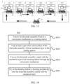
- This application relates to the technical field of batteries, and in particular, to a device and method for assembling a battery cell.
- Electric vehicles have become an important part of the sustainable development of the automobile industry by virtue of energy saving and environmental friendliness. Battery technology is crucial to development of electric vehicles.
- Some embodiments of this application provide a device and method for assembling a battery cell to improve the assembling efficiency of battery cells.
- a device for assembling a battery cell including: a conveyance mechanism, configured to fix an electrode assembly and convey the electrode assembly to a coating station; a coating mechanism, configured to coat at least a part of an outer surface of the electrode assembly with an insulation layer at the coating station, where the conveyance mechanism is further configured to: convey the electrode assembly coated with the insulation layer to an encasing station; and an encasing mechanism, configured to fit, at the encasing station, a housing peripherally onto the electrode assembly coated with the insulation layer.
- the device for assembling a battery cell fixes the electrode assembly and conveys the electrode assembly between different workstations through the conveyance mechanism to implement the processes such as coating the electrode assembly with the insulation layer and encasing the electrode assembly in the housing, thereby avoiding the need to repeatedly change the transport tool during the handling and conveyance of the electrode assembly.
- This simplifies the assembling process of the battery cell improves the assembling efficiency of the battery cell, reduces the damage to the electrode assembly that may be caused by an external force in a case of using different transport tools, improves the qualification rate of battery cells, and in turn, improves the yield rate of the battery.
- the conveyance mechanism is configured to carry the electrode assembly and an end cap.
- the end cap is attached to a first end face of the electrode assembly.
- a carrier surface of the conveyance mechanism is attached to a surface of the end cap, the surface being away from the electrode assembly.
- the electrode assembly is placed on the conveyance mechanism along a first direction, where the first direction is perpendicular to the first end face.
- the conveyance mechanism can simultaneously convey the electrode assembly and the end cap to perform the subsequent assembling process, thereby improving the processing and assembling efficiency of the battery cell.
- the coating mechanism is configured to: control the insulation layer to move along the first direction so that the insulation layer approaches the electrode assembly and coats at least a part of the outer surface of the electrode assembly.
- the electrode assembly is placed on the conveyance mechanism along the first direction. Therefore, the coating mechanism controls the insulation layer to move along the first direction and gradually approach the electrode assembly, so that the insulation layer can coat the electrode assembly from an end face of the electrode assembly, the end face being disposed opposite to the first end face.
- the coating process is simple and easy to implement.
- the outer surface of the electrode assembly can be coated with the insulation layer without turning the electrode assembly over while the electrode assembly keeps being placed on the conveyance mechanism along the first direction.
- the encasing mechanism is configured to: orient an opening of the housing toward the electrode assembly, and control the housing to move along the first direction so that the electrode assembly coated with the insulation layer enters the housing from the opening. An opening is created on the housing.
- the electrode assembly coated with the insulation layer is disposed on the conveyance mechanism along the first direction.
- the encasing mechanism controls the housing to move along the first direction and gradually approach the electrode assembly, and the opening of the housing is oriented toward the electrode assembly. Therefore, without turning over the electrode assembly, the housing can be fitted peripherally onto the electrode assembly coated with the insulation layer, so as to implement the encasing process of the electrode assembly. The process is simple and easy to implement.
- the conveyance mechanism includes: a clamping assembly, configured to clamp the electrode assembly along a second direction, where the second direction is perpendicular to the first direction; a driving assembly, configured to apply a driving force to the clamping assembly along a third direction so that the clamping assembly is configured to release the electrode assembly under the driving force.
- the clamping assembly clamps the electrode assembly along the second direction, and the second direction is perpendicular to the first direction, and therefore, in a case that the first direction is perpendicular to the first end face, the second direction is parallel to the first end face.
- a conveyance direction in which the conveyance mechanism conveys the electrode assembly coated with the insulation layer from the coating station to the encasing station is different from the third direction.
- the driving assembly is likely to affect the conveyance of the conveyance mechanism. For example, the conveyance mechanism that is conveying the electrode assembly needs to be dodged, thereby increasing the difficulty in the design of the driving assembly. Conversely, if the conveyance direction of the conveyance mechanism in conveying the electrode assembly is different from the third direction, the driving assembly causes no hindrance to the movement of the conveyance assembly, thereby facilitating the arrangement of the driving assembly.
- the clamping assembly includes: two clamping modules spaced apart along the second direction, where the electrode assembly is located between the two clamping modules; and a moving module movably linked with the two clamping modules.
- the two clamping modules are configured to: when the moving module moves along the third direction, move away from each other along the second direction to release the electrode assembly, or move closer to each other along the second direction to clamp the electrode assembly.
- the third direction is different from the second direction.
- the two clamping modules are set to be movably linked with the moving module, so that the movement of the two clamping modules can be driven by the movement of the moving module, thereby enabling the clamping modules to clamp and release the electrode assembly, and facilitating the mounting and removal of the electrode assembly.
- the movement direction of the moving module is the third direction, and the third direction is different from the second direction, thereby making it more flexible and easier to position the moving module.
- the clamping assembly includes: a retaining structure, where the retaining structure is connected to the moving module.
- the retaining structure is configured to retain the moving module in a target position.
- the two clamping modules are configured to clamp the electrode assembly along the second direction when the moving module is located in the target position. Under the action of the retaining structure, the moving module is located in the target position.
- the two clamping modules are located close to each other, thereby enabling the two clamping modules to clamp the electrode assembly along the second direction.
- the retaining structure includes a spring extending along the third direction.
- the spring When the spring is not subjected to an external force, the spring is automatically restored to its original state, and pushes the moving module to settle in the target position, thereby enabling the two clamping modules to clamp the electrode assembly.
- the structure is simple and easy to implement.
- the spring is configured to: be compressed along the third direction when the driving assembly applies a driving force to the moving module along the third direction, and be restored to an original position along the third direction when the driving assembly stops applying the driving force to the moving module.
- the spring structure can deform under the driving force and, when the driving force stops acting, be restored to its original form so that the moving module returns to the target position.
- the structure is simple and is easy to implement.
- the moving module includes a slide slot structure.
- Each clamping module of the at least two clamping modules includes a protrusion structure. At least a part of the protrusion structure is accommodated in the slide slot structure and moves in the slide slot structure.
- the slide slot structure accommodates at least a part of the protrusion structure so that the protrusion structure can slide in the slide slot structure. In this way, with reasonable design of the slide slot structure, the two clamping modules with a protrusion structure are enabled to be movably linked to the moving module with a slide slot structure.
- the structure is simple and easy to implement.
- an extension direction of the slide slot structure is different from the third direction and different from the second direction. In this way, when the driving assembly applies a driving force to the moving module along the third direction, the two clamping modules can move along the second direction different from the third direction by virtue of the setting of the extension direction of the slide slot structure.
- the moving module includes two slide slot structures.
- the two slide slot structures correspond to the protrusion structures of the at least two clamping modules one to one. Considering that an electrode assembly is disposed between the two clamping modules according to this embodiment of this application, the two clamping modules are at a distance from each other. Correspondingly, the two protrusion structures of the two clamping modules are also at a distance from each other. Therefore, two slide slot structures can be disposed to accommodate the two protrusion structures respectively. In this way, the two slide slot structures are free from mutual interference, thereby improving the structural reliability.
- the two slide slot structures are at equal angles to the second direction.
- the two slide slot structures may be made to be at equal angles to the second direction. In this way, the protrusion structures of the two clamping modules move synchronously, thereby synchronizing the movement of the two clamping modules, and improving the clamping efficiency of the two clamping modules.
- each of the two clamping modules is configured to clamp two second end faces of the electrode assembly.
- the two second end faces are disposed opposite to each other and perpendicular to the first end face.
- the two clamping modules clamp the two opposite second end faces of the electrode assembly, so that the clamping force exerted on the electrode assembly is relatively uniform, thereby keeping the balance of the electrode assembly on the carrier surface, and improving the stability of the electrode assembly on the conveyance mechanism.
- the clamping assembly further includes: a carrier module.
- the carrier module and the moving module are stacked along the first direction, and the carrier module is close to the electrode assembly.
- a surface, oriented toward the electrode assembly, of the carrier module is the carrier surface. Disposing the carrier module between the moving module and the electrode assembly facilitates the carrier module to carry the electrode assembly without affecting the movement of the moving module under the driving force of the driving assembly.
- the structure is easy to implement.
- the driving assembly is disposed at the coating station and/or the encasing station.
- the coating mechanism coats at least a part of an outer surface of the electrode assembly with an insulation layer.
- the first end face of the electrode assembly is not necessarily coated with the insulation layer but all other end faces of the electrode assembly need to be coated with the insulation layer, the end faces of the electrode assembly clamped by the two clamping modules may also need to be coated with the insulation layer.
- the driving assembly disposed at the coating station may exert a driving force to make the clamping modules release the electrode assembly, so as to coat the outer surface of the electrode assembly with the insulation layer.
- the electrode assembly coated with the insulation layer enters the interior of the housing from the opening of the housing. Therefore, the driving assembly disposed at the encasing station may exert a driving force to make the two clamping modules release the electrode assembly, so as to let the electrode assembly into the housing.
- the third direction is perpendicular to the first direction. Therefore, when the moving module moves as driven by a driving force, the electrode assembly can still remain relatively stable on the carrier surface under its own gravity, thereby preventing the position of the electrode assembly from being affected by the movement of the moving module.
- the third direction is perpendicular to the second direction.
- the movement direction of the moving module is perpendicular to the movement direction of the clamping modules, thereby avoiding mutual interference with respect to the movement position.
- the driving assembly applies a driving force along the third direction, no hindrance is caused to the movement of the two clamping modules.
- the structure design is simplified and easy to implement.
- a method for assembling a battery cell including: conveying an electrode assembly fixed to a conveyance mechanism to a coating station; coating at least a part of an outer surface of the electrode assembly with an insulation layer at the coating station; conveying the electrode assembly coated with the insulation layer to an encasing station through the conveyance mechanism; and fitting, at the encasing station, a housing peripherally onto the electrode assembly coated with the insulation layer.
- the conveyance mechanism is configured to carry the electrode assembly and an end cap.
- the end cap is attached to a first end face of the electrode assembly.
- a carrier surface of the conveyance mechanism is attached to a surface of the end cap, the surface being away from the electrode assembly.
- the electrode assembly is placed on the conveyance mechanism along a first direction, where the first direction is perpendicular to the first end face.
- the conveyance mechanism includes a clamping assembly and a driving assembly.
- the clamping assembly is configured to clamp the electrode assembly along a second direction, where the second direction is perpendicular to the first direction.
- the driving assembly is configured to apply a driving force to the clamping assembly along a third direction so that the clamping assembly is configured to release the electrode assembly under the driving force.
- a conveyance direction in which the conveyance mechanism conveys the electrode assembly coated with the insulation layer from the coating station to the encasing station is different from the third direction.
- the clamping assembly is configured to clamp two second end faces of the electrode assembly.
- the two second end faces are disposed opposite to each other and perpendicular to the first end face.
- neither the first end face nor the second end faces is a largest-area end face of the electrode assembly.
- a plurality of means at least two in number; the terms such as “up”, “down”, “left”, “right”, “in”, and “out” indicating a direction or a position relationship are merely intended for ease or brevity of description of this application, but do not indicate or imply that the mentioned device or component is necessarily located in the specified direction and position or constructed or operated in the specified direction and position. Therefore, such terms are not to be understood as a limitation on this application.
- the terms “first”, “second”, “third”, and so on are merely used for descriptive purposes, but not construed as indicating or implying relative importance.
- Perfect does not means exact perpendicularity, but means perpendicularity falling within an error tolerance range.
- Parallel does not mean exact parallelism, but means parallelism falling within an error tolerance range.
- connection may be a fixed connection, a detachable connection, or an integrated connection, and may be a direct connection or an indirect connection implemented through an intermediary.
- the battery mentioned in this application means a unitary physical module that includes one or more battery cells to provide a higher voltage and a higher capacity.
- the battery mentioned in this application may include a battery module, a battery pack, or the like.
- a battery typically includes a box configured to package one or more battery cells. The box prevents liquid or other foreign matters from affecting the charging or discharging of the battery cells.
- a battery cell may include types such as a lithium-ion secondary battery, a lithium-ion primary battery, a lithium-sulfur battery, a sodium-lithium-ion battery, a sodium-ion battery, or a magnesium-ion battery.
- the type of the battery cell is not limited herein.
- a battery cell is briefly referred to as a cell.
- the battery cell may be in the shape of a cylinder, a flat body, a cuboid, or another regular or irregular shape. The technical solution disclosed in an embodiment of this application is applicable to battery cells of any shape.
- a battery cell includes an electrode assembly and an electrolyte solution.
- the electrode assembly includes a positive electrode plate, a negative electrode plate, and a separator.
- the battery cell works primarily by shuttling metal ions between the positive electrode plate and the negative electrode plate.
- the positive electrode plate includes a positive current collector and a positive active material layer. A surface of the positive current collector is coated with the positive active material layer. Of the current collector, a part not coated with the positive active material layer protrudes from a part coated with the positive active material layer, and the part not coated with the positive active material layer serves as a positive tab.
- the positive current collector may be made of aluminum, and a positive active material may be lithium cobalt oxide, lithium iron phosphate, ternary lithium, lithium manganese oxide, or the like.
- the negative electrode plate includes a negative current collector and a negative active material layer. A surface of the negative current collector is coated with the negative active material layer. Of the current collector, a part not coated with the negative active material layer protrudes from a part coated with the negative active material layer, and the part not coated with the negative active material layer serves as a negative tab.
- the negative current collector may be made of copper, and a negative active material may be carbon, silicon, or the like.
- the separator may be made of a material such as polypropylene (Polypropylene, PP) or polyethylene (Polyethylene, PE).
- the development of the battery technology needs to consider a plurality of design factors, including performance metrics such as energy density, cycle life, discharge capacity, charge rate, and discharge rate, and also needs to consider the processing efficiency and yield rate of the batteries.
- performance metrics such as energy density, cycle life, discharge capacity, charge rate, and discharge rate
- the processing efficiency of batteries may be improved by improving the processing efficiency of battery cells.
- the production process of a battery cell is very sophisticated.
- the production process typically includes a processing and assembling process of an electrode assembly, the fitting between the electrode assembly and the end cap, the fitting of the electrode assembly into a housing, the fitting between the housing and an end cap, and the like. Therefore, the production efficiency of the battery cell drastically restricts the production efficiency of batteries.
- the manufacturing process of battery cells is not sound, the yield rate of the battery cells will decline in the manufacturing process, or, the battery cells may incur some defects or performance problems, and even have a shorter service life, thereby impairing the performance of the battery. Therefore, how to effectively improve the production efficiency and product yield rate of battery cells is one of the key challenges in the battery field.
- an embodiment of this application provides a device for assembling a battery cell.
- the device includes a conveyance mechanism. Through the conveyance mechanism, an electrode assembly is fixed, and conveyed between different workstations.
- the conveyance mechanism conveys the electrode assembly to a coating station.
- a coating mechanism coats at least a part of an outer surface of the electrode assembly with an insulation layer.
- the conveyance mechanism conveys the electrode assembly coated with the insulation layer to an encasing station.
- the encasing mechanism fits a housing peripherally onto the electrode assembly coated with the insulation layer.
- the conveyance mechanism conveys the electrode assembly to different workstations sequentially to implement the processes such as coating the electrode assembly with the insulation layer and encasing the electrode assembly in the housing, thereby avoiding the need to repeatedly change the transport tool during the handling and conveyance of the electrode assembly.
- This simplifies the assembling process of the battery cell improves the assembling efficiency of the battery cell, reduces the damage to the electrode assembly that may be caused by an external force in a case of using different transport tools, improves the qualification rate of battery cells, and in turn, improves the yield rate of the battery.
- the electrical device may be a vehicle, a mobile phone, a portable device, a notebook computer, a ship, a spacecraft, an electric toy, a power tool, or the like.
- the vehicle may be an oil-fueled vehicle, a natural gas vehicle, or a new energy vehicle.
- the new energy vehicle may be a battery electric vehicle, a hybrid electric vehicle, a range-extended electric vehicle, or the like.
- the spacecraft includes an airplane, a rocket, a space shuttle, a spaceship, and the like.
- the electric toy includes a fixed or mobile electric toy, such as a game console, an electric car toy, an electric ship toy, an electric airplane toy, and the like.
- the power tool includes an electrical metal cutting tool, an electrical grinding tool, an electrical assembling tool, and a power tool for use in railways.
- Examples of the power tool are an electrical drill, an electrical grinder, an electrical wrench, an electrical screwdriver, an electrical hammer, an electrical impact drill, a concrete vibrator, an electrical planer, and the like.
- the electrical device is not particularly limited in this embodiment of this application.
- the battery may include a plurality of battery cells.
- the plurality of battery cells may be connected in series, parallel, or series-and-parallel pattern.
- the series-and-parallel pattern means a combination of series connection and parallel connection.
- the battery may also be referred to as a battery pack.
- the plurality of battery cells may be connected in series, parallel, or series-and-parallel pattern to form a battery module, and then a plurality of battery modules may be connected in series, parallel, or series-and-parallel pattern to form the battery.
- the plurality of battery cells may directly form the battery, or form the battery modules that are then used to form the battery.
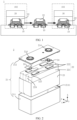
- FIG. 1 is a schematic block diagram of a device 1 for assembling a battery cell 2 according to an embodiment of this application.
- the device 1 according to this embodiment of this application includes: a conveyance mechanism 10, configured to fix an electrode assembly 22 and convey the electrode assembly 22 to a coating station 102; a coating mechanism 20, configured to coat at least a part of an outer surface of the electrode assembly 22 with an insulation layer 23 at the coating station 102, where the conveyance mechanism 10 is further configured to: convey the electrode assembly 22 coated with the insulation layer 23 to an encasing station 103; and an encasing mechanism 30, configured to fit, at the encasing station 103, a housing 211 peripherally onto the electrode assembly 22 coated with the insulation layer 23.
- the device 1 conveys the electrode assembly 22 to different workstations sequentially through the conveyance mechanism 10.
- the conveyance mechanism 10 may convey the electrode assembly 22 to a coating station 102.
- a coating mechanism 20 coats at least a part of an outer surface of the electrode assembly 22 with an insulation layer 23.
- the conveyance mechanism 10 may convey the electrode assembly 22 coated with the insulation layer 23 to an encasing station 103.
- the encasing mechanism 30 fits a housing 211 peripherally onto the electrode assembly 22 coated with the insulation layer 23.
- the conveyance mechanism 10 conveys the electrode assembly 22, thereby avoiding the need to repeatedly change the transport tool, simplifying the assembling process of the battery cell 2, improving the assembling efficiency of the battery cell 2, reducing the damage to the electrode assembly 22 that may be caused by an external force in a case of using different transport tools, improving the qualification rate of battery cells 2, and in turn, improving the yield rate of the battery cells.
- the device 1 may be configured to assemble a battery cell 2.
- the structure of the battery cell 2 may be flexibly designed depending on actual applications.
- FIG. 2 is a possible schematic exploded view of a battery cell 2 according to an embodiment of this application. The following describes the structure of the battery cell 2, using FIG. 2 as an example.
- the battery cell 2 may include one or more electrode assemblies 22 and a shell 21 configured to accommodate the electrode assembly 22.
- the shell 21 in this embodiment of this application may assume a polyhedral structure.
- the shell 21 may include a housing 211 and an end cap 212.
- the housing 211 may be a hollow structure opened at least at one end.
- the shape of the end cap 212 may be adapted to the shape of the housing 211.
- the end cap 212 is configured to fit and cover the opening of the housing 211 so that the shell 21 isolates the internal environment of the battery cell 2 from the external environment. If the housing 211 is a hollow structure opened at one end, one end cap 212 may be disposed, as shown in FIG. 2 , for example. Alternatively, if the housing 211 is a hollow structure opened at two opposite ends, two end caps 212 may be disposed. The two end caps 212 fit and cover the openings at the two ends of the housing 211 respectively.
- the housing 211 in this embodiment of this application may be made of a variety of materials such as copper, iron, aluminum, steel, or aluminum alloy.
- the end cap 212 may be made of a variety of materials such as copper, iron, aluminum, steel, or an aluminum alloy.
- the material of the end cap 212 may be identical to or different from the material of the housing 211.
- the shell 21 in this embodiment of this application may be in various shapes such as a cylinder or cuboid.
- the shape of the housing 211 and the shape of the end cap 212 are adapted to each other.
- the housing 211 is a cuboidal structure
- the end cap 212 is a rectangular plate structure adapted to the housing 211.
- the shell 21 includes: a housing 211, where the housing 211 is a hollow structure opened at one end; and an end cap 212, where the end cap 212 is configured to fit and cover the opening of the housing 211 to form a closed cavity in which the electrode assembly 22 is placed.
- the interior of the housing 211 is configured to accommodate an electrode assembly 22.
- the number of electrode assemblies 22 in the housing 211 may be one or more.
- FIG. 2 shows an example in which the battery cell 2 includes four electrode assemblies 22 arranged along the thickness direction Z of the electrode assemblies 22, but the embodiments of this application are not limited to the example.
- the electrode assembly 22 in an embodiment of this application is a component in which electrochemical reactions occur in the battery cell 2.
- the electrode assembly 22 may be cylindrical, cuboidal, or the like. If the electrode assembly 22 is cylindrical, the housing 211 may be cylindrical accordingly. If the electrode assembly 22 is cuboidal, the housing 211 may be cuboidal accordingly.
- the electrode assembly 22 may include a tab 222 and a main portion 221. Specifically, as shown in FIG. 2 , the electrode assembly 22 may include at least two tabs 222. The at least two tabs 222 may include at least one positive tab and at least one negative tab.
- the positive tab may be a stacked part, uncoated with a positive active material layer, on a positive electrode plate; and the negative tab may be a stacked part, uncoated with a negative active material layer, on a negative electrode plate.
- electrode terminals 214 are disposed on the shell 21 in an embodiment of this application.
- the electrode terminals 214 are configured to be electrically connected to the electrode assembly 22 to output electrical energy of the battery cell 2.
- the battery cell 2 may further include at least two electrode terminals 214.
- the at least two electrode terminals 214 may be disposed on the same wall or different walls of the battery cell 2.
- FIG. 2 shows an example in which the battery cell 2 includes two electrode terminals 214, and both of the two electrode terminals 214 are disposed on the end cap 212.
- the end cap 212 is typically in the shape of a flat plate. Two electrode terminals 214 are fixed onto a flat surface of the end cap 212.
- the two electrode terminals 214 are a positive electrode terminal and a negative electrode terminal respectively.
- a connecting member 24 is disposed corresponding to each electrode terminal 214.
- the connecting member 24 is located between the end cap 212 and the electrode assembly 22, and configured to electrically connect the electrode assembly 22 and the electrode terminal 214.
- the positive tab of the electrode assembly 22 may be connected to a positive electrode terminal by one connecting member 24.
- the negative tab of the electrode assembly 22 is connected to a negative electrode terminal by another connecting member 24.
- the battery cell 2 further includes an insulation layer 23.
- the insulation layer 23 is a hollow structure on which at least one opening is created.
- this application describes a typical example in which one opening is created on the insulation layer 23.
- the opening is oriented toward the end cap 212.
- the insulation layer 23 is disposed between the housing 211 and the electrode assembly 22.
- the hollow structure of the insulation layer 23 is configured to accommodate the electrode assembly 22, so that the insulation layer 23 coats at least a part of an outer surface of the electrode assembly 22.
- the insulation layer 23 may be configured to maintain electrical insulation between the electrode assembly 22 and an inner wall of the housing 211.
- the insulation layer 23 may be a thin-film cover layer made of an insulating material, and may coat at least a part of the outer surface of the electrode assembly 22.
- the insulation layer 23 may be a sheet structure before coating the electrode assembly 22.
- the coating mechanism 20 makes a hollow opened structure of the insulation layer that coats the outer surface of the electrode assembly 22.
- the shape of the insulation layer 23 may be determined depending on the shape of the electrode assembly 22 or the shape of the housing 211.
- the insulation layer 23 may be, but is not limited to, a cuboidal shape.
- the battery cell 20 may further include a pressure relief mechanism.
- the assembling process of the battery cell 2 may be designed flexibly as required in practical applications in view of the structural characteristics of the battery cell 2.
- the following describes the assembling process of some components of the battery cell 2, using the battery cell 2 shown in FIG. 2 as an example.
- the device 1 may include a conveyance mechanism 10.
- the conveyance mechanism 10 is configured to fix and convey an electrode assembly 22.
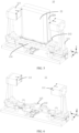
- FIG. 3 is a schematic structural diagram of a conveyance mechanism 10 according to an embodiment of this application
- FIG. 4 is a schematic structural diagram of a conveyance mechanism 10 to which an electrode assembly 22 is fixed according to an embodiment of this application.
- the conveyance mechanism 10 shown in FIG. 4 may be the conveyance mechanisms 10 shown in FIG. 1 and FIG. 3 .
- the conveyance mechanism 10 includes a carrier surface 101 configured to carry the electrode assembly 22.
- a first end face 223 of the electrode assembly 22 faces the carrier surface 101 so that the electrode assembly 22 is placed on the conveyance mechanism 10 along a first direction X.
- the first direction X is perpendicular to the first end face 223.
- the insulation layer 23 usually does not need to coat the entire surface of the electrode assembly 22 when the insulation layer 23 is applied.
- the insulation layer 23 may not need to coat a first end face 223 of the electrode assembly 22.
- the first end face 223 that does not need to be coated with the insulation layer 23 can be oriented toward the carrier surface 101 without interfering with the coating process of the insulation layer 23. Therefore, the electrode assembly 22 does not need to be turned over when applying the insulation layer 23, thereby avoiding damage to the electrode assembly 22.
- the first end face 223 is oriented toward the carrier surface 101, and the electrode assembly 22 is disposed on the conveyance mechanism 10 along the first direction X. This enables the electrode assembly 22 to be placed on the conveyance mechanism 10 by virtue of the gravity of the electrode assembly, thereby facilitating placement of the electrode assembly and improving the stability of the electrode assembly 22 on the conveyance mechanism 10.
- the electrode terminals 214 of the end cap 212 may be connected to the corresponding tabs 222 by a connecting member 24, so that the end cap 212 is relatively fixed to the electrode assembly 22. In this way, the end cap 212 and the electrode assembly 22 can be processed together subsequently.
- the conveyance mechanism 10 may be configured to carry the electrode assembly 22 and the end cap 212, where the carrier surface 101 of the conveyance mechanism 10 is in contact with a surface of the end cap 212, the surface being away from the electrode assembly 22; and a surface, close to the electrode assembly 22, of the end cap 212, is attached to the first end face 223. In this way, the conveyance mechanism 10 can simultaneously convey the electrode assembly 22 and the end cap 212 to perform the subsequent assembling process, thereby improving the processing efficiency of the battery cell 2.
- the carrier surface 101 in this embodiment of this application is a surface of the conveyance mechanism 10.
- the surface may be a flat and even surface that facilitates processing of the conveyance mechanism 10.
- the carrier surface 101 may be an uneven surface.
- the form of the carrier surface 101 may be designed depending on the form of the component in contact with the carrier surface.
- the carrier surface 101 is in contact with the surface of the end cap 212.
- Some protruding or recessed components may exist on a surface, away from the electrode assembly 22, of the end cap 212. Therefore, the surface, away from the electrode assembly 22, of the end cap 212 is usually uneven.
- the carrier surface 101 may also be uneven, so as to be adapted to the surface, away from the electrode assembly 22, of the end cap 212.
- an electrode terminal 214 is disposed on the end cap 212.
- the electrode terminal 214 is disposed protrusively on the surface, away from the electrode assembly 22, of the end cap 212. Accordingly, a recessed region may be created on the carrier surface 101.
- the recessed region may be configured to accommodate the electrode terminal 214, so that the surface of the end cap 212 is adapted to the carrier surface 101.
- positioning can be implemented by using the correspondence between the protruding part and the recessed region, thereby facilitating accurate placement of the end cap 212 and the electrode assembly 22 on the carrier surface 101.
- this enables the end cap 212 to be more stably disposed on the carrier surface 101, thereby improving the conveyance stability of the conveyance mechanism 10.
- this reduces the abrasion caused by the carrier surface 101 onto the surface of the end cap 212, and improves the qualification rate of the battery cells 2.
- FIG. 5 is another schematic structural diagram of a conveyance mechanism 10 on which an electrode assembly 22 is disposed according to an embodiment of this application.
- FIG. 5 differs from FIG. 4 in that the conveyance mechanism 10 shown in FIG. 4 clamps the electrode assembly 22, but the conveyance mechanism 10 shown in FIG. 5 releases the electrode assembly 22.
- FIG. 6 is a schematic diagram of a partial structure of a conveyance mechanism 10 according to an embodiment of this application.
- the conveyance structure 10 shown in FIG. 6 differs from the conveyance mechanism 10 in FIG. 3 by removing a structure that is configured to carry the electrode assembly 22.
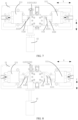
- FIG. 7 to FIG. 9 are schematic top views of the conveyance mechanism 10 in several different states according to some embodiments of this application.
- FIG. 7 to FIG. 9 are schematic top views of a part of the conveyance mechanism 10 shown in FIG. 6 .
- the conveyance mechanism 10 includes: a clamping assembly 11, configured to clamp the electrode assembly 22 along a second direction Y, where the second direction Y is perpendicular to the first direction X; a driving assembly 12, configured to apply a driving force to the clamping assembly 11 along a third direction Z so that the clamping assembly 11 is configured to release the electrode assembly 22 under the driving force.
- the clamping assembly 11 clamps the electrode assembly 22 along the second direction Y, and the second direction Y is perpendicular to the first direction X. Therefore, in a case that the first direction X is perpendicular to the first end face 223, the second direction Y is parallel to the first end face 223.
- the clamping assembly 11 clamps the electrode assembly 22, the first end face 223 of the electrode assembly 22 is still oriented toward the carrier surface 101 without being interfered with. Therefore, when the electrode assembly 22 is placed on the conveyance mechanism 10, the electrode assembly is not only subjected to its own gravity, but also subjected to a clamping force along the second direction Y, thereby further ensuring the stability of the electrode assembly 22 on the conveyance mechanism 10.
- the clamping assembly 11 can move along the second direction Y to release the electrode assembly 22 under the driving force applied by the driving assembly 12 along the third direction Z, thereby facilitating the removal of the electrode assembly 22.
- the clamping assembly 11 can be made to move under the driving force applied by the driving assembly 12 along the third direction Z, so that the electrode assembly 22 can be placed in the conveyance mechanism 10.
- the driving assembly 22 in this embodiment of this application applies a driving force along the third direction Z
- the third direction Z may be set flexibly depending on practical applications.
- the third direction Z may be the same as or different from the second direction Y in which the clamping assembly 11 clamps the electrode assembly 22. If the third direction Z is set to be different from the second direction Y, the position of the driving assembly 12 can be set more flexibly to prevent the driving assembly 12 from hindering the movement process of the clamping assembly 11.
- the conveyance direction in which the conveyance mechanism 10 conveys the electrode assembly 22 coated with the insulation layer 23 from the coating station 102 to the encasing station 103 is different from the third direction Z.
- the driving assembly 12 is likely to affect the conveyance of the conveyance mechanism 10. For example, when the conveyance mechanism 10 is conveying the electrode assembly 22, the conveyance mechanism 10 needs to be dodged, thereby increasing the difficulty in the design of the driving assembly 12. Conversely, if the conveyance direction of the conveyance mechanism 10 in conveying the electrode assembly 22 is different from the third direction Z, the driving assembly 12 causes no hindrance to the movement of the conveyance assembly 22, thereby facilitating the arrangement of the driving assembly 12.
- the driving assembly 12 in this embodiment of this application may be implemented in various ways.
- the driving assembly 12 may be a cylinder, but this embodiment of this application is not limited to the example.
- the clamping assembly 11 includes: two clamping modules 111 spaced apart along the second direction Y, where the electrode assembly 22 is located between the two clamping modules 111; and a moving module 112 movably linked with the two clamping modules 111.
- the two clamping modules 111 are configured to: when the moving module 112 moves along the third direction Z, move away from each other along the second direction Y to release the electrode assembly 22, or move closer to each other along the second direction Y to clamp the electrode assembly 22.
- the third direction Z is different from the second direction Y
- the two clamping modules 111 are set to be movably linked with the moving module 112, so that the movement of the two clamping modules 111 can be driven by the movement of the moving module 112, thereby enabling the clamping modules 111 to clamp and release the electrode assembly 22, and facilitating the mounting and removal of the electrode assembly 22.
- the movement direction of the moving module 112 is the third direction Z
- the third direction Z is different from the second direction Y, thereby making it more flexible and easier to position the moving module 112.
- the third direction Z in this embodiment of this application may include two opposite directions, so that the moving module 112 can reciprocate along the third direction Z.
- the second direction Y in this embodiment of this application may include two opposite directions, so that each of the two clamping modules 111 can reciprocate along the second direction Y, thereby making the two clamping modules 111 approach each other or depart from each other.
- the retaining structure 113 in this embodiment of this application may be implemented in various ways.
- the retaining structure 113 includes a spring 1131 extending along the third direction Z.
- the spring 1131 is automatically restored to its original state, and pushes the moving module 112 to settle in the target position, thereby enabling the two clamping modules 111 to clamp the electrode assembly 22.
- the structure is simple and easy to implement.
- the type of the spring 1131 in this embodiment of this application may be set flexibly depending on practical applications.
- the spring 1131 may be a compression spring or a tension spring.
- the type of the spring is not limited herein.
- the moving module 112 moves along the third direction Z.
- the third direction Z is a vertical upward direction shown in FIG. 8 , that is, the driving assembly 12 applies a driving force to the moving module 112 along the vertical upward third direction Z shown in FIG. 8 .
- the moving module 112 moves along the vertical upward third direction Z correspondingly.
- the two clamping modules 111 movably linked with the moving module 112 move away from each other along the second direction Y, so that the distance between the two clamping modules 111 increases gradually, and the clamping force of the two clamping modules 111 on the electrode assembly 22 decreases gradually.
- the two clamping modules 111 movably linked with the moving module 112 also move away from each other along the second direction Y until the spacing between two clamping modules is maximized.
- the electrode assembly 22 can be removed from between the two clamping modules 111. In other words, the electrode assembly 22 is removed from the conveyance mechanism 10.
- the driving force is greater than the retaining force of the retaining structure 113, so that the moving module 112 is caused to move away from the target position.
- the spring 1131 is configured to: be compressed along the third direction Z when the driving assembly 12 applies a driving force to the moving module 112 along the third direction Z.
- the spring 1131 can be compressed.
- the driving assembly 12 gradually increases the driving force along the vertical upward third direction Z. Conversely, from FIG. 9 to FIG. 7 , it is deemed that the driving assembly 12 gradually decreases the driving force along the vertical upward third direction Z.
- the electrode assembly 22 may be placed between the two clamping modules 111 when the distance between the two clamping modules 111 is maximized. In this way, the electrode assembly 22 is placed on the conveyance mechanism 10.
- the driving force applied by the driving assembly 12 along the vertical upward third direction Z decreases gradually. Therefore, the moving module 112 gradually moves along the vertical downward third direction Z under the action of the retaining structure 113. At this time, the two clamping modules 111 movably linked with the moving module 112 approach each other along the second direction Y That is, the distance between the two clamping modules 111 gradually decreases. Therefore, the two clamping modules 111 can gradually approach the electrode assembly 22 and gradually clamp the electrode assembly 22.
- the retention structure 113 enables the moving module 112 to gradually approach the target position.
- the retaining structure 113 is a spring 1131
- the spring 1131 is configured to be restored to the original state along the third direction Z when the driving assembly 12 stops applying the driving force to the moving module 112.
- the spring 1131 is gradually restored from the compressed state until the driving assembly 12 stops applying the driving force.
- the spring 1131 is restored to the original state along the third direction Z.
- the moving module 112 moves to the target position, and remains in the target position when the driving assembly 12 applies no driving force.
- the two clamping modules 111 movably linked with the moving module 112 can keep clamping the electrode assembly 22 so as to fix the electrode assembly 22.
- the target position of the moving module 112 may be set based on the dimensions of the clamped electrode assembly 22, so that the two clamping modules 111 can clamp the electrode assembly 22.
- the moving module 112 can still return to the target position, and the two clamping modules 111 approach each other but without clamping any component.
- the linkage of the moving module 112 to the two clamping modules 111 may be implemented in various ways.
- the linkage of the moving module 112 to the two clamping modules 111 may be implemented by disposing a slide slot and a protrusion movable in the slide slot.
- the moving module 112 includes a slide slot structure 1121.
- Each clamping module 111 of the at least two clamping modules 111 includes a protrusion structure 1111, and at least a part of the protrusion structure 1111 is accommodated in the slide slot structure 1121 and moves in the slide slot structure 1121.
- the slide slot structure 1121 accommodates at least a part of the protrusion structure 1111 so that the protrusion structure 1111 can slide in the slide slot structure 1121.
- the two clamping modules 111 with a protrusion structure 1111 are enabled to be movably linked to the moving module 112 with a slide slot structure 1121.
- the structure is simple and easy to implement.
- the extension direction of the slide slot structure 1121 may be set depending on practical applications.
- the extension direction of the slide slot structure 1121 may be determined based on the second direction Y and the third direction Z.
- the extension direction of the slide slot structure 1121 is different from the third direction Z and different from the second direction Y In this way, when the driving assembly 12 applies a driving force to the moving module 112 along the third direction Z, the two clamping modules 111 can move along the second direction Y different from the third direction Z by virtue of the setting of the extension direction of the slide slot structure 1121.
- the extension direction of this slide slot structure 1121 may be related to at least one of the following parameters: the movement speed of the moving module 112, the movement speed of the two clamping modules 111, the magnitude of the driving force exerted by the driving assembly 12, or the elasticity coefficient of the spring 1131.
- the extension direction of the slide slot structure 1121 may be determined based on at least one of the above parameters, but this embodiment of this application is not limited to the example.
- the moving module 112 includes two slide slot structures 1121.
- the two slide slot structures 1121 correspond to the protrusion structures 1111 of the at least two clamping modules 111 one to one.
- the two clamping modules 111 are at a distance from each other.
- the two protrusion structures 1111 of the two clamping modules 111 are also at a distance from each other. Therefore, two slide slot structures 1121 can be disposed to accommodate the two protrusion structures 1111 respectively. In this way, the two slide slot structures 1121 are free from mutual interference, thereby improving the structural reliability.
- the two slide slot structures 1121 are at equal angles to the second direction Y
- the two slide slot structures 1121 may be made to be at equal angles to the second direction Y In this way, the protrusion structures 1111 of the two clamping modules 111 move synchronously, thereby synchronizing the movement of the two clamping modules 111, and improving the clamping efficiency of the two clamping modules 111.
- each of the two clamping modules 111 is configured to clamp two second end faces 224 of the electrode assembly 22.
- the two second end faces 224 are disposed opposite to each other and perpendicular to the first end face 223.
- the two clamping modules 111 clamp the two opposite second end faces 224 of the electrode assembly 22, so that the clamping force exerted on the electrode assembly 22 is relatively uniform, thereby keeping the balance of the electrode assembly 22 on the carrier surface 101, and improving the stability of the electrode assembly 22 on the conveyance mechanism 10.
- the specific structure of the two clamping modules 111 in this embodiment of this application may be set flexibly depending on practical applications.
- the two clamping modules 111 may be set to be a mutually symmetrical structures. Therefore, when the two clamping modules 111 clamp the electrode assembly 22, the clamping force exerted on the electrode assembly 22 is relatively uniform, so as to maintain the stability of the electrode assembly 22.
- each clamping module 111 in this embodiment of this application may be a columnar structure.
- the size of the contact region between each clamping module 111 and the electrode assembly 22 may be set flexibly depending on practical applications, and is not limited herein.
- the above description uses an example in which the retaining structure 113 includes a spring 1131 extending along the third direction Z.
- the retaining structure 113 may be implemented by other means.
- the linkage of the moving module 112 to the two clamping modules 111 may be implemented by other structures.
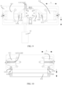
- FIG. 10 is another schematic top view of a conveyance mechanism 10 according to an embodiment of this application.
- FIG. 10 shows another possible structure of the retention structure 113 according to an embodiment of this application, and also shows a possible structure of the moving module 112 and the clamping modules 111 according to an embodiment of this application.
- the retaining structure 113 of the conveyance mechanism 10 may include a spring 1132 extending along the second direction Y Specifically, the spring 1132 extending along the second direction Y may correspond one-to-one to the two clamp modules 111. That is, each spring 1132 is connected to a corresponding clamping module 111.
- the moving module 112 of the conveyance mechanism 10 may include a wedge-shaped surface 1122.
- each clamping module 111 of the two clamping modules 111 includes a cam 1112.
- the cam 1112 may move along the wedge-shaped surface 1122, so that the moving module 111 is movably linked with the two clamping modules 111.
- the moving module 112 moves along the third direction Z.
- the cams 1112 of the two clamping modules 111 move along the wedge-shaped surface 1122, so that the two clamping modules 111 move away from each other along the second direction Y to release the electrode assembly 22 or place the electrode assembly 22.
- the spring 1132 deforms under the action of the clamping modules 111.
- the driving assembly 12 gradually decreases the driving force until the driving force is stopped, the spring 1132 returns to its original form, pushes the two clamping modules 111 to gradually approach each other to clamp the electrode assembly 22.
- the moving module 112 moves along the third direction Z to return to the target position.
- the moving module 112 may be located outside the clamping module 111 when staying in the target position, and may be separated from the two clamping modules 111. Therefore, the moving module 112 in this embodiment may be disposed separately from the two clamping modules 111. In this way, when the two clamping modules 111 clamp the electrode assembly 22 and move to different workstations, the moving module 112 does not move, and the moving module 112 can be fixed to a corresponding workstation.
- the position of the moving module 112 may be flexibly set depending on practical applications.
- the moving module 112 is disposed at the coating station 102 and/or the encasing station 103. Therefore, when the two clamping modules 111 clamp the electrode assembly 22 and move to the station, the moving module 112 can make the two clamping modules 111 move to release or clamp the electrode assembly 22.
- this embodiment of this application is not limited to the example.
- the clamping assembly 11 further includes: a carrier module 114.
- the carrier module 114 and the moving module 112 are stacked along the first direction X, and the carrier module is close to the electrode assembly 22.
- a surface, oriented toward the electrode assembly 22, of the carrier module 114 is the carrier surface 101. Disposing the carrier module 114 between the moving module 112 and the electrode assembly 22 facilitates the carrier module 114 to carry the electrode assembly 22 without affecting the movement of the moving module 112 under the driving force of the driving assembly 12.
- the structure is easy to implement.
- the structure of the carrier module 114 in this embodiment of this application may be set depending on practical applications.
- the carrier module 114 may be a plate-like structure.
- the moving module 112 may also be a plate-like structure. In this way, the carrier module 114 and the moving module 112 are stacked together, thereby facilitating the processing and assembling of the two modules, reducing the overall size of the conveyance mechanism 10, and simplifying the overall structure of the device 1.
- the position of the driving assembly 12 may be flexibly set depending on practical applications.
- the driving assembly 12 may be set reasonably based on the work content of each different workstation.
- the driving assembly 12 is disposed at the coating station 102 and/or the encasing station 103.
- the coating mechanism 20 coats at least a part of an outer surface of the electrode assembly 22 with an insulation layer 23.
- the first end face 223 of the electrode assembly 22 does not need to be coated with the insulation layer 23 but all other end faces of the electrode assembly 22 need to be coated with the insulation layer 23, the end faces of the electrode assembly 22 clamped by the two clamping modules 111 may also need to be coated with the insulation layer 23.
- the driving assembly 22 disposed at the coating station 102 may exert a driving force to make the clamping modules 111 release the electrode assembly 22, so as to coat the outer surface of the electrode assembly 22 with the insulation layer 23.
- the electrode assembly 22 coated with the insulation layer 23 enters the interior of the housing 211 from the opening 2111 of the housing 211. Therefore, the driving assembly 22 disposed at the encasing station 103 may exert a driving force to make the two clamping modules 111 release the electrode assembly 22, so as to let the electrode assembly 22 into the housing 211.
- the moving module 112 moves along the third direction Z, and the third direction Z may be set flexibly depending on practical applications.
- the third direction Z is perpendicular to the first direction X. Therefore, when the moving module 112 moves as driven by a driving force, the electrode assembly 22 can still remain relatively stable on the carrier surface 101 under its own gravity, thereby preventing the position of the electrode assembly 22 from being affected by the movement of the moving module 112.
- the third direction Z is perpendicular to the second direction Y
- the movement direction of the moving module 112 is perpendicular to the movement direction of the clamping modules 111, thereby avoiding mutual interference with respect to the movement position.
- the driving assembly 12 applies a driving force along the third direction Z, no hindrance is caused to the movement of the two clamping modules 111.
- the structure design is simplified and easy to implement.
- the extension direction of the slide slot structure 1121 may be located between the third direction Z and the second direction Y, and, for example, may be at an angle of 45° to the third direction Z and also an angle of 45° to the second direction Y In this way, the movement speed of the moving module 112 is equal to that of the clamping modules 111, thereby facilitating control.
- this embodiment of this application is not limited to the example.
- FIG. 11 is a possible schematic structural diagram of a coating mechanism 20 according to an embodiment of this application.
- the coating mechanism 20 is configured to: control the insulation layer 23 to move along the first direction X so that the insulation layer 23 approaches the electrode assembly 22 and coats at least a part of the outer surface of the electrode assembly 22.
- the electrode assembly 22 is placed on the conveyance mechanism 10 along the first direction X.
- the coating mechanism 20 controls the insulation layer 23 to move along the first direction X and gradually approach the electrode assembly 22, so that the insulation layer 23 can coat the electrode assembly 22 from an end face of the electrode assembly 22, the end face being disposed opposite to the first end face 223.
- the coating process is simple and easy to implement.
- the outer surface of the electrode assembly 22 can be coated with the insulation layer 23 without turning the electrode assembly 22 over while the electrode assembly 22 keeps being placed on the conveyance mechanism 10 along the first direction X.
- the coating mechanism 20 may include: at least one film gripping structure and a bracket 205.
- the at least one film gripping structure is disposed on the bracket 205.
- the at least one film gripping structure includes four film gripping structures, herein referred to as a first film gripping structure 201, a second film gripping structure 202, a third film gripping structure 203, and a fourth film gripping structure 204.
- the four film gripping structures are configured to clamp the corner regions of the insulation layer 23, respectively.
- this embodiment of this application is not limited to the example.
- the coating mechanism 20 may further include a fixing structure so that the bracket 205 is fixed as a whole to the fixing structure and movable relative to the fixing structure.
- the bracket 205 may move relative to the fixing structure along the first direction X.
- the first direction X includes a vertical upward direction, and the bracket 205 may move vertically upward or vertically downward along the first direction X, so as to move away from or closer to the electrode assembly 22 that is fixed to the conveyance mechanism 10.
- the bracket 205 includes at least one film gripping structure.
- the at least one film gripping structure is configured to clamp and fix the insulation layer 23.
- four film gripping structures clamp four corners of the insulation layer 23 respectively.
- the first film gripping structure 201 and the second film gripping structure 202 clamp a first part 231 of the insulation layer 23 and then turn over toward the electrode assembly 22 along the dashed line.
- the third film gripping structure 203 and the fourth film gripping structure 204 clamp the second part 233 of the insulation layer 23, and are turned over toward the electrode assembly 22 along the dashed line.
- a connecting part 232 located between the first part 231 and the second part 233 corresponds to an end face of the electrode assembly 22.
- the end face corresponding to the connecting part 232 may be an end face opposite to the first end face 223 of the electrode assembly 22.
- the connecting part 232 coats the end face opposite to the first end face 223 of the electrode assembly 22, and then the four film gripping structures clamp the insulation layer 23 and turn over to enable the insulation layer 23 to coat other end faces of the electrode assembly 22.
- FIG. 12 is a possible schematic structural diagram of an encasing mechanism 30 according to an embodiment of this application.
- the encasing mechanism 30 is configured to: orient an opening 2111 of the housing 211 toward the electrode assembly 22, and control the housing 211 to move along the first direction X so that the electrode assembly 22 coated with the insulation layer 23 enters the housing 211 from the opening.
- An opening 2111 is created on the housing 211.
- the electrode assembly 22 coated with the insulation layer 23 is disposed on the conveyance mechanism 10 along the first direction X.
- the encasing mechanism 30 controls the housing 211 to move along the first direction X and gradually approach the electrode assembly 22.
- the opening 2111 of the housing 211 is oriented toward the electrode assembly 22. Therefore, without turning over the electrode assembly 22, the housing 211 can be fitted peripherally onto the electrode assembly 22 coated with the insulation layer 23, so as to implement the encasing process of the electrode assembly 22.
- the process is simple and easy to implement.
- the encasing mechanism 30 may include: a supporting component 301, a driving component 302, and a housing fixing component 303.
- the housing fixing component 303 is fixed onto the supporting component 301.
- the driving component 302 may also be fixed onto the supporting component 301, so as to facilitate the processing and assembling of the encasing mechanism 30.
- the housing fixing component 303 may be configured to fix the housing 211.
- the housing fixing component 303 may include a bottom gripping structure 3031 and an opening gripping structure 3032.
- the bottom gripping structure 3031 may be configured to clamp and fix a bottom of the housing 211.
- the bottom of the housing 211 includes a bottom wall of the housing 211 and a part of a sidewall of the housing 211, the part surrounding and abutting the bottom wall.
- the bottom wall of the housing 211 is a wall opposite to the opening 2111 of the housing 211.
- the sidewall of the housing 211 is a wall adjacent to the opening 2111 of the housing 211 and configured to close in to form the opening 2111.
- the opening gripping structure 3032 is configured to clamp and fix a part of the sidewall of the housing 211, the part being close to the opening 2111. In this way, the opening 2111 can be directed to the electrode assembly 22, so that the housing 211 can be fitted peripherally onto the electrode assembly 22 accurately to complete the encasing process of the electrode assembly 22.
- FIG. 13 shows another schematic block diagram of a device 1 according to an embodiment of this application.
- the device 1 according to this embodiment of this application may further include: a loading mechanism 40, configured to fix the electrode assembly 22 to the conveyance mechanism 10 at a loading station 104.
- the conveyance mechanism 10 is further configured to: convey the electrode assembly 22 from the loading station 104 to another station, for example, to the coating station 102.
- the loading mechanism 40 may place the electrode assembly 22 onto the conveyance mechanism 10 along the first direction X.
- the first direction X is a vertical direction. Therefore, at the loading station 104, the clamping module 111 of the conveyance mechanism 10 can clamp and fix the electrode assembly 22, so that the conveyance mechanism 10 can convey the electrode assembly 22 and continue moving to other stations to start assembling the battery cell 2.
- a driving assembly 12 may be disposed at the loading station 104 so that the driving assembly 12 provides a driving force for the conveyance mechanism 10.
- the clamping modules 111 of the clamping assembly 11 are move away from each other, thereby increasing the distance between the two clamping modules 111. Therefore, the loading mechanism 40 can dispose the electrode assembly 22, or the interconnected electrode assembly and end cap 212, between the two clamping modules 111, so as to fix the electrode assembly 22.
- the device 1 may further include: a first detection mechanism 50, configured to detect a defect of the electrode assembly 22 at a first detection station 105.
- the conveyance mechanism 10 is further configured to: convey the electrode assembly 22, which has passed through the first detection station 105, to another station, for example, to the coating station 102.
- the first detection station 105 may be located between the loading station 104 and the coating station 102.
- defects of the electrode assembly 22 may be detected by the first detection mechanism 50 at the first detection station 105, so as to detect and handle the electrode assembly 22 with defects in time, and avoid impairing the performance of the battery cell 2 containing the electrode assembly 22.
- the first detection mechanism 50 may be a charge coupled device (CCD) detection mechanism, so that a CCD camera can take pictures and detect defects.
- CCD charge coupled device
- the type of the first detection mechanism is not limited herein.
- the conveyance direction of the conveyance mechanism 10 in conveying the electrode assembly 22 in this embodiment of this application may be set depending on practical applications.
- the conveyance mechanism 10 conveys the electrode assembly 22 from left to right.
- the conveyance mechanism 10 conveys the electrode assembly 22 from the loading station 104 to the first detection station 105, and then to the coating station 102, and so forth.
- this embodiment of this application is not limited to the example.
- the device 1 may further include: a second detection mechanism 60, configured to detect, at a second detection station 106, an effect of coating the electrode assembly 22 with the insulation layer 23.
- the conveyance mechanism 10 is further configured to: convey the electrode assembly 22 coated with the insulation layer 23, which has passed through the second detection station 106, to another station, for example, further to the encasing station 103.
- the second detection station 106 may be located between the coating station 102 and the encasing station 103. After the electrode assembly 22 is coated with the insulation layer 23, the coated electrode assembly 22 may be subjected to other processes.
- the insulation layer 23 may be subjected to a hot-melt treatment.
- the electrode assembly 22 coated with the insulation layer 23 may be further subjected to an adhesive bonding treatment. Therefore, the electrode assembly 22 coated with the insulation layer 23 may be detected for defects by the second detection mechanism 60 at the second detection station 106, so as to detect and handle defective regions in time, for example, detect a region of adhesive nonconformity in time, so as to avoid impairing the performance of the assembled battery cell 2.
- the second detection mechanism 60 may be a CCD detection mechanism, so that a CCD camera can take pictures and detect defects.
- the type of the second detection mechanism is not limited herein.
- the conveyance mechanism 10 conveys the electrode assembly 22 coated with the insulation layer 23 from the coating station 102 to the second detection station 106, and may further convey the electrode assembly from the second detection station 106 to the encasing station 103. In this way, at the encasing station 103, the encasing mechanism 30 fits the housing 211 peripherally onto the electrode assembly 22 coated with the insulation layer 23.
- the device 1 further includes: an unloading mechanism 70, configured to detach the electrode assembly 22 fitted with the housing 211 from the conveyance mechanism 10 at an unloading station 107, so that the electrode assembly 22 fitted with the housing 211 is ready for subsequent processes.
- the conveyance mechanism 10 in this embodiment of this application may convey the electrode assembly 22 fitted with the housing 211 from the encasing station 103 further to the unloading station 107.
- the unloading mechanism 70 may detach the electrode assembly 22 fitted with the housing 211 from the conveyance mechanism 10 along the first direction X.
- the first direction X is a vertical direction.
- the clamping module 111 of the conveyance mechanism 10 can release the electrode assembly 22, so that the conveyance mechanism 10 can be detached from the electrode assembly 22 fitted with the housing 211.
- the conveyance mechanism 10 is reused cyclically and continues to fix and convey other electrode assemblies 22.
- the electrode assembly 22 fitted with the housing 211 can proceed to other subsequent assembling steps to form an assembled battery cell 2.
- the conveyance mechanism 10 further includes: a control assembly 13, configured to control the clamping assembly 11 to move between different workstations.
- a control assembly 13 configured to control the clamping assembly 11 to move between different workstations.
- the control assembly 13 may be configured to control the clamping assembly 11 to move steadily between the different workstations to convey the clamped electrode assembly 22.
- the control assembly 13 may be a magnetic driving device configured to magnetically drive the movement of the clamping assembly 11 to maintain the stability and movement rate of the electrode assembly 22.
- the conveyance mechanism 10 may return to the loading station 104 to fix a next electrode assembly 22.
- the control assembly 13 may be another type of device that can save time and cost.
- the control assembly 13 may include a conveyor belt. The conveyor belt conveys the clamping assembly 11 back to the loading station 104 quickly to complete one cycle, that is, complete one process by which the electrode assembly 22 is encased in the housing.
- the device 1 conveys the electrode assembly 22 to different workstations sequentially through the conveyance mechanism 10.
- the conveyance mechanism 10 may convey the electrode assembly 22 to a coating station 102.
- a coating mechanism 20 coats at least a part of an outer surface of the electrode assembly 22 with an insulation layer 23.
- the conveyance mechanism 10 may convey the electrode assembly 22 coated with the insulation layer 23 to an encasing station 103.
- the encasing mechanism 30 fits a housing 211 peripherally onto the electrode assembly 22 coated with the insulation layer 23.
- the conveyance mechanism 10 conveys the electrode assembly 22, thereby avoiding the need to repeatedly change the transport tool, simplifying the assembling process of the battery cell 2, improving the assembling efficiency of the battery cell 2, reducing the damage to the electrode assembly 22 that may be caused by an external force in a case of using different transport tools, improving the qualification rate of battery cells 2, and in turn, improving the yield rate of batteries.
- the device 1 for assembling a battery cell 2 according to some embodiments of this application has been described above with reference to drawings.
- the following describes a method for assembling a battery cell 2 according to an embodiment of this application.
- FIG. 14 is a schematic flowchart of a method 800 for assembling a battery cell 2 according to an embodiment of this application.
- the method 800 may include: S810. conveying an electrode assembly 22 fixed to a conveyance mechanism 10 to a coating station 102; S820. coating at least a part of an outer surface of the electrode assembly 22 with an insulation layer 23 at the coating station 102; S830. conveying the electrode assembly 22 coated with the insulation layer 23 to an encasing station 103 through the conveyance mechanism 10; and S840. fitting, at the encasing station 103, a housing 211 peripherally onto the electrode assembly 22 coated with the insulation layer 23.
- the conveyance mechanism 10 is configured to carry the electrode assembly 22 and an end cap 212.
- the end cap 212 is attached to a first end face 223 of the electrode assembly 22.
- a carrier surface 101 of the conveyance mechanism is attached to a surface of the end cap 212, the surface being away from the electrode assembly 22.
- the electrode assembly 22 is placed on the conveyance mechanism 10 along a first direction X, and the first direction X is perpendicular to the first end face 223.
- the conveyance mechanism 10 includes a clamping assembly 11 and a driving assembly 12.
- the clamping assembly 11 is configured to clamp the electrode assembly 22 along a second direction Y, where the second direction Y is perpendicular to the first direction X.
- the driving assembly 12 is configured to apply a driving force to the clamping assembly 11 along a third direction Z so that the clamping assembly 11 is configured to release the electrode assembly 22 under the driving force.
- a conveyance direction in which the conveyance mechanism 10 conveys the electrode assembly 22 coated with the insulation layer 23 from the coating station 102 to the encasing station 103 is different from the third direction Z.
- the clamping assembly 11 is configured to clamp two second end faces of the electrode assembly 22.
- the two second end faces are disposed opposite to each other and perpendicular to the first end face 223.
- neither the first end face 223 nor the second end faces is a largest-area end face of the electrode assembly 22.
Landscapes
- Chemical & Material Sciences (AREA)
- Chemical Kinetics & Catalysis (AREA)
- Electrochemistry (AREA)
- General Chemical & Material Sciences (AREA)
- Engineering & Computer Science (AREA)
- Manufacturing & Machinery (AREA)
- Battery Mounting, Suspending (AREA)
Abstract
Description
- This application relates to the technical field of batteries, and in particular, to a device and method for assembling a battery cell.
- Energy conservation and emission reduction are key to sustainable development of the automobile industry. Electric vehicles have become an important part of the sustainable development of the automobile industry by virtue of energy saving and environmental friendliness. Battery technology is crucial to development of electric vehicles.
- With the development of the battery technology, the performance of a battery is not only affected by the battery material, but is also crucially bottlenecked by the manufacturing process of the battery. Therefore, how to improve the processing and production efficiency of batteries is one of the key challenges in the battery field.
- Some embodiments of this application provide a device and method for assembling a battery cell to improve the assembling efficiency of battery cells.
- According to a first aspect, a device for assembling a battery cell is provided, including: a conveyance mechanism, configured to fix an electrode assembly and convey the electrode assembly to a coating station; a coating mechanism, configured to coat at least a part of an outer surface of the electrode assembly with an insulation layer at the coating station, where the conveyance mechanism is further configured to: convey the electrode assembly coated with the insulation layer to an encasing station; and an encasing mechanism, configured to fit, at the encasing station, a housing peripherally onto the electrode assembly coated with the insulation layer.
- The device for assembling a battery cell according to this embodiment of this application fixes the electrode assembly and conveys the electrode assembly between different workstations through the conveyance mechanism to implement the processes such as coating the electrode assembly with the insulation layer and encasing the electrode assembly in the housing, thereby avoiding the need to repeatedly change the transport tool during the handling and conveyance of the electrode assembly. This simplifies the assembling process of the battery cell, improves the assembling efficiency of the battery cell, reduces the damage to the electrode assembly that may be caused by an external force in a case of using different transport tools, improves the qualification rate of battery cells, and in turn, improves the yield rate of the battery.
- In some embodiments, the conveyance mechanism is configured to carry the electrode assembly and an end cap. The end cap is attached to a first end face of the electrode assembly. A carrier surface of the conveyance mechanism is attached to a surface of the end cap, the surface being away from the electrode assembly. The electrode assembly is placed on the conveyance mechanism along a first direction, where the first direction is perpendicular to the first end face. The conveyance mechanism can simultaneously convey the electrode assembly and the end cap to perform the subsequent assembling process, thereby improving the processing and assembling efficiency of the battery cell.
- In some embodiments, the coating mechanism is configured to: control the insulation layer to move along the first direction so that the insulation layer approaches the electrode assembly and coats at least a part of the outer surface of the electrode assembly. The electrode assembly is placed on the conveyance mechanism along the first direction. Therefore, the coating mechanism controls the insulation layer to move along the first direction and gradually approach the electrode assembly, so that the insulation layer can coat the electrode assembly from an end face of the electrode assembly, the end face being disposed opposite to the first end face. The coating process is simple and easy to implement. In addition, the outer surface of the electrode assembly can be coated with the insulation layer without turning the electrode assembly over while the electrode assembly keeps being placed on the conveyance mechanism along the first direction.
- In some embodiments, the encasing mechanism is configured to: orient an opening of the housing toward the electrode assembly, and control the housing to move along the first direction so that the electrode assembly coated with the insulation layer enters the housing from the opening. An opening is created on the housing. The electrode assembly coated with the insulation layer is disposed on the conveyance mechanism along the first direction. The encasing mechanism controls the housing to move along the first direction and gradually approach the electrode assembly, and the opening of the housing is oriented toward the electrode assembly. Therefore, without turning over the electrode assembly, the housing can be fitted peripherally onto the electrode assembly coated with the insulation layer, so as to implement the encasing process of the electrode assembly. The process is simple and easy to implement.
- In some embodiments, the conveyance mechanism includes: a clamping assembly, configured to clamp the electrode assembly along a second direction, where the second direction is perpendicular to the first direction; a driving assembly, configured to apply a driving force to the clamping assembly along a third direction so that the clamping assembly is configured to release the electrode assembly under the driving force.
- The clamping assembly clamps the electrode assembly along the second direction, and the second direction is perpendicular to the first direction, and therefore, in a case that the first direction is perpendicular to the first end face, the second direction is parallel to the first end face. This ensures that, when the clamping assembly clamps the electrode assembly, the first end face of the electrode assembly is still oriented toward the carrier surface without being interfered with. Therefore, when the electrode assembly is placed on the conveyance mechanism, the electrode assembly is not only subjected to its own gravity, but also subjected to a clamping force along the second direction, thereby further ensuring the stability of the electrode assembly on the conveyance mechanism.
- In some embodiments, a conveyance direction in which the conveyance mechanism conveys the electrode assembly coated with the insulation layer from the coating station to the encasing station is different from the third direction.
- If the conveyance direction of the conveyance mechanism in conveying the electrode assembly is the same as the third direction, the driving assembly is likely to affect the conveyance of the conveyance mechanism. For example, the conveyance mechanism that is conveying the electrode assembly needs to be dodged, thereby increasing the difficulty in the design of the driving assembly. Conversely, if the conveyance direction of the conveyance mechanism in conveying the electrode assembly is different from the third direction, the driving assembly causes no hindrance to the movement of the conveyance assembly, thereby facilitating the arrangement of the driving assembly.
- In some embodiments, the clamping assembly includes: two clamping modules spaced apart along the second direction, where the electrode assembly is located between the two clamping modules; and a moving module movably linked with the two clamping modules. The two clamping modules are configured to: when the moving module moves along the third direction, move away from each other along the second direction to release the electrode assembly, or move closer to each other along the second direction to clamp the electrode assembly. The third direction is different from the second direction.
- The two clamping modules are set to be movably linked with the moving module, so that the movement of the two clamping modules can be driven by the movement of the moving module, thereby enabling the clamping modules to clamp and release the electrode assembly, and facilitating the mounting and removal of the electrode assembly. In addition, the movement direction of the moving module is the third direction, and the third direction is different from the second direction, thereby making it more flexible and easier to position the moving module.
- In some embodiments, the clamping assembly includes: a retaining structure, where the retaining structure is connected to the moving module. The retaining structure is configured to retain the moving module in a target position. The two clamping modules are configured to clamp the electrode assembly along the second direction when the moving module is located in the target position. Under the action of the retaining structure, the moving module is located in the target position. Correspondingly, the two clamping modules are located close to each other, thereby enabling the two clamping modules to clamp the electrode assembly along the second direction.
- In some embodiments, the retaining structure includes a spring extending along the third direction. When the spring is not subjected to an external force, the spring is automatically restored to its original state, and pushes the moving module to settle in the target position, thereby enabling the two clamping modules to clamp the electrode assembly. The structure is simple and easy to implement.
- In some embodiments, the spring is configured to: be compressed along the third direction when the driving assembly applies a driving force to the moving module along the third direction, and be restored to an original position along the third direction when the driving assembly stops applying the driving force to the moving module. The spring structure can deform under the driving force and, when the driving force stops acting, be restored to its original form so that the moving module returns to the target position. The structure is simple and is easy to implement.
- In some embodiments, the moving module includes a slide slot structure. Each clamping module of the at least two clamping modules includes a protrusion structure. At least a part of the protrusion structure is accommodated in the slide slot structure and moves in the slide slot structure. The slide slot structure accommodates at least a part of the protrusion structure so that the protrusion structure can slide in the slide slot structure. In this way, with reasonable design of the slide slot structure, the two clamping modules with a protrusion structure are enabled to be movably linked to the moving module with a slide slot structure. The structure is simple and easy to implement.
- In some embodiments, an extension direction of the slide slot structure is different from the third direction and different from the second direction. In this way, when the driving assembly applies a driving force to the moving module along the third direction, the two clamping modules can move along the second direction different from the third direction by virtue of the setting of the extension direction of the slide slot structure.
- In some embodiments, the moving module includes two slide slot structures. The two slide slot structures correspond to the protrusion structures of the at least two clamping modules one to one. Considering that an electrode assembly is disposed between the two clamping modules according to this embodiment of this application, the two clamping modules are at a distance from each other. Correspondingly, the two protrusion structures of the two clamping modules are also at a distance from each other. Therefore, two slide slot structures can be disposed to accommodate the two protrusion structures respectively. In this way, the two slide slot structures are free from mutual interference, thereby improving the structural reliability.
- In some embodiments, the two slide slot structures are at equal angles to the second direction. Considering that the two clamping modules usually need to move synchronously, for example, approach each other or depart from each other, the two slide slot structures may be made to be at equal angles to the second direction. In this way, the protrusion structures of the two clamping modules move synchronously, thereby synchronizing the movement of the two clamping modules, and improving the clamping efficiency of the two clamping modules.
- In some embodiments, each of the two clamping modules is configured to clamp two second end faces of the electrode assembly. The two second end faces are disposed opposite to each other and perpendicular to the first end face. The two clamping modules clamp the two opposite second end faces of the electrode assembly, so that the clamping force exerted on the electrode assembly is relatively uniform, thereby keeping the balance of the electrode assembly on the carrier surface, and improving the stability of the electrode assembly on the conveyance mechanism.
- In some embodiments, the clamping assembly further includes: a carrier module. The carrier module and the moving module are stacked along the first direction, and the carrier module is close to the electrode assembly. A surface, oriented toward the electrode assembly, of the carrier module is the carrier surface. Disposing the carrier module between the moving module and the electrode assembly facilitates the carrier module to carry the electrode assembly without affecting the movement of the moving module under the driving force of the driving assembly. The structure is easy to implement.
- In some embodiments, the driving assembly is disposed at the coating station and/or the encasing station. At the coating station, the coating mechanism coats at least a part of an outer surface of the electrode assembly with an insulation layer. Considering that the first end face of the electrode assembly is not necessarily coated with the insulation layer but all other end faces of the electrode assembly need to be coated with the insulation layer, the end faces of the electrode assembly clamped by the two clamping modules may also need to be coated with the insulation layer. In this case, the driving assembly disposed at the coating station may exert a driving force to make the clamping modules release the electrode assembly, so as to coat the outer surface of the electrode assembly with the insulation layer. At the encasing station, the electrode assembly coated with the insulation layer enters the interior of the housing from the opening of the housing. Therefore, the driving assembly disposed at the encasing station may exert a driving force to make the two clamping modules release the electrode assembly, so as to let the electrode assembly into the housing.
- In some embodiments, the third direction is perpendicular to the first direction. Therefore, when the moving module moves as driven by a driving force, the electrode assembly can still remain relatively stable on the carrier surface under its own gravity, thereby preventing the position of the electrode assembly from being affected by the movement of the moving module.
- In some embodiments, the third direction is perpendicular to the second direction. In this way, the movement direction of the moving module is perpendicular to the movement direction of the clamping modules, thereby avoiding mutual interference with respect to the movement position. In addition, when the driving assembly applies a driving force along the third direction, no hindrance is caused to the movement of the two clamping modules. The structure design is simplified and easy to implement.
- According to a second aspect, a method for assembling a battery cell is provided, including: conveying an electrode assembly fixed to a conveyance mechanism to a coating station; coating at least a part of an outer surface of the electrode assembly with an insulation layer at the coating station; conveying the electrode assembly coated with the insulation layer to an encasing station through the conveyance mechanism; and fitting, at the encasing station, a housing peripherally onto the electrode assembly coated with the insulation layer.
- In some embodiments, the conveyance mechanism is configured to carry the electrode assembly and an end cap. The end cap is attached to a first end face of the electrode assembly. A carrier surface of the conveyance mechanism is attached to a surface of the end cap, the surface being away from the electrode assembly. The electrode assembly is placed on the conveyance mechanism along a first direction, where the first direction is perpendicular to the first end face.
- In some embodiments, the conveyance mechanism includes a clamping assembly and a driving assembly. The clamping assembly is configured to clamp the electrode assembly along a second direction, where the second direction is perpendicular to the first direction. The driving assembly is configured to apply a driving force to the clamping assembly along a third direction so that the clamping assembly is configured to release the electrode assembly under the driving force.
- In some embodiments, a conveyance direction in which the conveyance mechanism conveys the electrode assembly coated with the insulation layer from the coating station to the encasing station is different from the third direction.
- In some embodiments, the clamping assembly is configured to clamp two second end faces of the electrode assembly. The two second end faces are disposed opposite to each other and perpendicular to the first end face.
- In some embodiments, neither the first end face nor the second end faces is a largest-area end face of the electrode assembly.
-
-
FIG. 1 is a schematic block diagram of a device for assembling a battery cell according to an embodiment of this application; -
FIG. 2 is a schematic exploded view of a battery cell according to an embodiment of this application; -
FIG. 3 is a schematic structural diagram of a conveyance mechanism according to an embodiment of this application; -
FIG. 4 is a schematic structural diagram of a conveyance mechanism that clamps an electrode assembly according to an embodiment of this application; -
FIG. 5 is a schematic structural diagram of a conveyance mechanism that releases an electrode assembly according to an embodiment of this application; -
FIG. 6 is a schematic diagram of a partial structure of a conveyance mechanism according to an embodiment of this application; -
FIG. 7 is a schematic top view of a partial structure of a conveyance mechanism according to an embodiment of this application; -
FIG. 8 is a schematic top view of another partial structure of a conveyance mechanism according to an embodiment of this application; -
FIG. 9 is a schematic top view of still another partial structure of a conveyance mechanism according to an embodiment of this application; -
FIG. 10 is a schematic top view of a partial structure of another conveyance mechanism according to an embodiment of this application; -
FIG. 11 is a schematic diagram of a partial structure of a coating mechanism according to an embodiment of this application; -
FIG. 12 is a schematic diagram of a partial structure of an encasing mechanism according to an embodiment of this application; -
FIG. 13 is a schematic block diagram of another device for assembling a battery cell according to an embodiment of this application; and -
FIG. 14 is a schematic flowchart of a method for assembling a battery cell according to an embodiment of this application. - The drawings are not drawn to scale.
- The following gives a more detailed description of implementations of this application with reference to drawings and embodiments. The detailed description of the following embodiments and drawings are intended to describe the principles of this application illustratively, but not to limit the scope of this application. Therefore, this application is not limited to the described embodiments.
- In the description of this application, unless otherwise specified, "a plurality of" means at least two in number; the terms such as "up", "down", "left", "right", "in", and "out" indicating a direction or a position relationship are merely intended for ease or brevity of description of this application, but do not indicate or imply that the mentioned device or component is necessarily located in the specified direction and position or constructed or operated in the specified direction and position. Therefore, such terms are not to be understood as a limitation on this application. In addition, the terms "first", "second", "third", and so on are merely used for descriptive purposes, but not construed as indicating or implying relative importance. "Perpendicular" does not means exact perpendicularity, but means perpendicularity falling within an error tolerance range. "Parallel" does not mean exact parallelism, but means parallelism falling within an error tolerance range.
- The directional terms appearing in the following description indicate the directions shown in the drawings, but are not intended to limit specific structures in this application. In the description of this application, unless otherwise expressly specified, the terms "mount", "concatenate", and "connect" are understood in a broad sense. For example, a "connection" may be a fixed connection, a detachable connection, or an integrated connection, and may be a direct connection or an indirect connection implemented through an intermediary. A person of ordinary skill in the art can understand the specific meanings of the terms in this application according to specific situations.
- In embodiments of this application, the same reference numeral denotes the same component. For brevity, detailed descriptions of the same component are omitted in a different embodiment. Understandably, dimensions such as thickness, length, and width of various components in some embodiments of this application shown in the drawings, and dimensions such as overall thickness, length, and width of an integrated device are merely illustrative descriptions, but do not constitute any limitation on this application.
- Reference to "embodiment" in this application means that a specific feature, structure or characteristic described with reference to the embodiment may be included in at least one embodiment of this application. Reference to this term in different places in the specification does not necessarily represent the same embodiment, nor does it represent an independent or alternative embodiment in a mutually exclusive relationship with other embodiments. A person skilled in the art explicitly and implicitly understands that an embodiment described in this application may be combined with another embodiment.
- Although this application has been described with reference to exemplary embodiments, various improvements may be made to the embodiments without departing from the scope of this application, and some components described in the embodiments may be replaced with equivalents. Particularly, to the extent that no structural conflict exists, various technical features mentioned in different embodiments may be combined in any manner. This application is not limited to the specific embodiments disclosed herein, but includes all technical solutions falling within the scope of the claims.
- The battery mentioned in this application means a unitary physical module that includes one or more battery cells to provide a higher voltage and a higher capacity. For example, the battery mentioned in this application may include a battery module, a battery pack, or the like. A battery typically includes a box configured to package one or more battery cells. The box prevents liquid or other foreign matters from affecting the charging or discharging of the battery cells.
- In some embodiments, a battery cell may include types such as a lithium-ion secondary battery, a lithium-ion primary battery, a lithium-sulfur battery, a sodium-lithium-ion battery, a sodium-ion battery, or a magnesium-ion battery. The type of the battery cell is not limited herein. Typically, a battery cell is briefly referred to as a cell. The battery cell may be in the shape of a cylinder, a flat body, a cuboid, or another regular or irregular shape. The technical solution disclosed in an embodiment of this application is applicable to battery cells of any shape.
- A battery cell includes an electrode assembly and an electrolyte solution. The electrode assembly includes a positive electrode plate, a negative electrode plate, and a separator. The battery cell works primarily by shuttling metal ions between the positive electrode plate and the negative electrode plate. The positive electrode plate includes a positive current collector and a positive active material layer. A surface of the positive current collector is coated with the positive active material layer. Of the current collector, a part not coated with the positive active material layer protrudes from a part coated with the positive active material layer, and the part not coated with the positive active material layer serves as a positive tab. Using a lithium-ion battery as an example, the positive current collector may be made of aluminum, and a positive active material may be lithium cobalt oxide, lithium iron phosphate, ternary lithium, lithium manganese oxide, or the like. The negative electrode plate includes a negative current collector and a negative active material layer. A surface of the negative current collector is coated with the negative active material layer. Of the current collector, a part not coated with the negative active material layer protrudes from a part coated with the negative active material layer, and the part not coated with the negative active material layer serves as a negative tab. The negative current collector may be made of copper, and a negative active material may be carbon, silicon, or the like. To prevent a large electrical current from tripping the circuit, a plurality of positive tabs are stacked together, and a plurality of negative tabs are stacked together. The separator may be made of a material such as polypropylene (Polypropylene, PP) or polyethylene (Polyethylene, PE).
- The development of the battery technology needs to consider a plurality of design factors, including performance metrics such as energy density, cycle life, discharge capacity, charge rate, and discharge rate, and also needs to consider the processing efficiency and yield rate of the batteries. For example, the processing efficiency of batteries may be improved by improving the processing efficiency of battery cells.
- The production process of a battery cell is very sophisticated. For example, the production process typically includes a processing and assembling process of an electrode assembly, the fitting between the electrode assembly and the end cap, the fitting of the electrode assembly into a housing, the fitting between the housing and an end cap, and the like. Therefore, the production efficiency of the battery cell drastically restricts the production efficiency of batteries. Moreover, if the manufacturing process of battery cells is not sound, the yield rate of the battery cells will decline in the manufacturing process, or, the battery cells may incur some defects or performance problems, and even have a shorter service life, thereby impairing the performance of the battery. Therefore, how to effectively improve the production efficiency and product yield rate of battery cells is one of the key challenges in the battery field.
- In view of this, an embodiment of this application provides a device for assembling a battery cell. The device includes a conveyance mechanism. Through the conveyance mechanism, an electrode assembly is fixed, and conveyed between different workstations. The conveyance mechanism conveys the electrode assembly to a coating station. At the coating station, a coating mechanism coats at least a part of an outer surface of the electrode assembly with an insulation layer. The conveyance mechanism conveys the electrode assembly coated with the insulation layer to an encasing station. At the encasing station, the encasing mechanism fits a housing peripherally onto the electrode assembly coated with the insulation layer. In this way, the conveyance mechanism conveys the electrode assembly to different workstations sequentially to implement the processes such as coating the electrode assembly with the insulation layer and encasing the electrode assembly in the housing, thereby avoiding the need to repeatedly change the transport tool during the handling and conveyance of the electrode assembly. This simplifies the assembling process of the battery cell, improves the assembling efficiency of the battery cell, reduces the damage to the electrode assembly that may be caused by an external force in a case of using different transport tools, improves the qualification rate of battery cells, and in turn, improves the yield rate of the battery.
- The technical solutions described in this embodiment of this application are applicable to various electrical devices that use a battery.
- The electrical device may be a vehicle, a mobile phone, a portable device, a notebook computer, a ship, a spacecraft, an electric toy, a power tool, or the like. The vehicle may be an oil-fueled vehicle, a natural gas vehicle, or a new energy vehicle. The new energy vehicle may be a battery electric vehicle, a hybrid electric vehicle, a range-extended electric vehicle, or the like. The spacecraft includes an airplane, a rocket, a space shuttle, a spaceship, and the like. The electric toy includes a fixed or mobile electric toy, such as a game console, an electric car toy, an electric ship toy, an electric airplane toy, and the like. The power tool includes an electrical metal cutting tool, an electrical grinding tool, an electrical assembling tool, and a power tool for use in railways. Examples of the power tool are an electrical drill, an electrical grinder, an electrical wrench, an electrical screwdriver, an electrical hammer, an electrical impact drill, a concrete vibrator, an electrical planer, and the like. The electrical device is not particularly limited in this embodiment of this application.
- To meet different power usage requirements, the battery may include a plurality of battery cells. The plurality of battery cells may be connected in series, parallel, or series-and-parallel pattern. The series-and-parallel pattern means a combination of series connection and parallel connection. The battery may also be referred to as a battery pack. Optionally, the plurality of battery cells may be connected in series, parallel, or series-and-parallel pattern to form a battery module, and then a plurality of battery modules may be connected in series, parallel, or series-and-parallel pattern to form the battery. In other words, the plurality of battery cells may directly form the battery, or form the battery modules that are then used to form the battery.
-
FIG. 1 is a schematic block diagram of adevice 1 for assembling abattery cell 2 according to an embodiment of this application. As shown inFIG. 1 , thedevice 1 according to this embodiment of this application includes: aconveyance mechanism 10, configured to fix anelectrode assembly 22 and convey theelectrode assembly 22 to acoating station 102; acoating mechanism 20, configured to coat at least a part of an outer surface of theelectrode assembly 22 with aninsulation layer 23 at thecoating station 102, where theconveyance mechanism 10 is further configured to: convey theelectrode assembly 22 coated with theinsulation layer 23 to anencasing station 103; and anencasing mechanism 30, configured to fit, at theencasing station 103, ahousing 211 peripherally onto theelectrode assembly 22 coated with theinsulation layer 23. - Therefore, the
device 1 according to this embodiment of this application conveys theelectrode assembly 22 to different workstations sequentially through theconveyance mechanism 10. For example, theconveyance mechanism 10 may convey theelectrode assembly 22 to acoating station 102. At thecoating station 102, acoating mechanism 20 coats at least a part of an outer surface of theelectrode assembly 22 with aninsulation layer 23. Subsequently, theconveyance mechanism 10 may convey theelectrode assembly 22 coated with theinsulation layer 23 to anencasing station 103. At theencasing station 103, theencasing mechanism 30 fits ahousing 211 peripherally onto theelectrode assembly 22 coated with theinsulation layer 23. In this process, theconveyance mechanism 10 conveys theelectrode assembly 22, thereby avoiding the need to repeatedly change the transport tool, simplifying the assembling process of thebattery cell 2, improving the assembling efficiency of thebattery cell 2, reducing the damage to theelectrode assembly 22 that may be caused by an external force in a case of using different transport tools, improving the qualification rate ofbattery cells 2, and in turn, improving the yield rate of the battery cells. - Understandably, the
device 1 according to this embodiment of this application may be configured to assemble abattery cell 2. The structure of thebattery cell 2 may be flexibly designed depending on actual applications. For example,FIG. 2 is a possible schematic exploded view of abattery cell 2 according to an embodiment of this application. The following describes the structure of thebattery cell 2, usingFIG. 2 as an example. As shown inFIG. 2 , thebattery cell 2 may include one ormore electrode assemblies 22 and ashell 21 configured to accommodate theelectrode assembly 22. - Understandably, as shown in
FIG. 2 , theshell 21 in this embodiment of this application may assume a polyhedral structure. Specifically, theshell 21 may include ahousing 211 and anend cap 212. Thehousing 211 may be a hollow structure opened at least at one end. The shape of theend cap 212 may be adapted to the shape of thehousing 211. Theend cap 212 is configured to fit and cover the opening of thehousing 211 so that theshell 21 isolates the internal environment of thebattery cell 2 from the external environment. If thehousing 211 is a hollow structure opened at one end, oneend cap 212 may be disposed, as shown inFIG. 2 , for example. Alternatively, if thehousing 211 is a hollow structure opened at two opposite ends, twoend caps 212 may be disposed. The twoend caps 212 fit and cover the openings at the two ends of thehousing 211 respectively. - The
housing 211 in this embodiment of this application may be made of a variety of materials such as copper, iron, aluminum, steel, or aluminum alloy. Theend cap 212 may be made of a variety of materials such as copper, iron, aluminum, steel, or an aluminum alloy. The material of theend cap 212 may be identical to or different from the material of thehousing 211. - The
shell 21 in this embodiment of this application may be in various shapes such as a cylinder or cuboid. The shape of thehousing 211 and the shape of theend cap 212 are adapted to each other. For example, as shown inFIG. 2 , thehousing 211 is a cuboidal structure, and theend cap 212 is a rectangular plate structure adapted to thehousing 211. - For ease of description, this application is described by using an example in which the
shell 21 is cuboidal. Specifically, as shown inFIG. 2 , theshell 21 includes: ahousing 211, where thehousing 211 is a hollow structure opened at one end; and anend cap 212, where theend cap 212 is configured to fit and cover the opening of thehousing 211 to form a closed cavity in which theelectrode assembly 22 is placed. - In the
battery cell 2, the interior of thehousing 211 is configured to accommodate anelectrode assembly 22. In addition, depending on actual use requirements, the number ofelectrode assemblies 22 in thehousing 211 may be one or more. For example,FIG. 2 shows an example in which thebattery cell 2 includes fourelectrode assemblies 22 arranged along the thickness direction Z of theelectrode assemblies 22, but the embodiments of this application are not limited to the example. - The
electrode assembly 22 in an embodiment of this application is a component in which electrochemical reactions occur in thebattery cell 2. Theelectrode assembly 22 may be cylindrical, cuboidal, or the like. If theelectrode assembly 22 is cylindrical, thehousing 211 may be cylindrical accordingly. If theelectrode assembly 22 is cuboidal, thehousing 211 may be cuboidal accordingly. - For any
electrode assembly 22, theelectrode assembly 22 may include atab 222 and amain portion 221. Specifically, as shown inFIG. 2 , theelectrode assembly 22 may include at least twotabs 222. The at least twotabs 222 may include at least one positive tab and at least one negative tab. The positive tab may be a stacked part, uncoated with a positive active material layer, on a positive electrode plate; and the negative tab may be a stacked part, uncoated with a negative active material layer, on a negative electrode plate. - Further,
electrode terminals 214 are disposed on theshell 21 in an embodiment of this application. Theelectrode terminals 214 are configured to be electrically connected to theelectrode assembly 22 to output electrical energy of thebattery cell 2. As shown inFIG. 2 , thebattery cell 2 may further include at least twoelectrode terminals 214. The at least twoelectrode terminals 214 may be disposed on the same wall or different walls of thebattery cell 2. For example,FIG. 2 shows an example in which thebattery cell 2 includes twoelectrode terminals 214, and both of the twoelectrode terminals 214 are disposed on theend cap 212. Theend cap 212 is typically in the shape of a flat plate. Twoelectrode terminals 214 are fixed onto a flat surface of theend cap 212. The twoelectrode terminals 214 are a positive electrode terminal and a negative electrode terminal respectively. A connectingmember 24 is disposed corresponding to eachelectrode terminal 214. The connectingmember 24 is located between theend cap 212 and theelectrode assembly 22, and configured to electrically connect theelectrode assembly 22 and theelectrode terminal 214. Specifically, as shown inFIG. 2 , the positive tab of theelectrode assembly 22 may be connected to a positive electrode terminal by one connectingmember 24. The negative tab of theelectrode assembly 22 is connected to a negative electrode terminal by another connectingmember 24. - Understandably, the
battery cell 2 according to an embodiment of this application further includes aninsulation layer 23. Theinsulation layer 23 is a hollow structure on which at least one opening is created. For example, as shown inFIG. 2 , this application describes a typical example in which one opening is created on theinsulation layer 23. In addition, the opening is oriented toward theend cap 212. Theinsulation layer 23 is disposed between thehousing 211 and theelectrode assembly 22. The hollow structure of theinsulation layer 23 is configured to accommodate theelectrode assembly 22, so that theinsulation layer 23 coats at least a part of an outer surface of theelectrode assembly 22. Theinsulation layer 23 may be configured to maintain electrical insulation between theelectrode assembly 22 and an inner wall of thehousing 211. For example, theinsulation layer 23 may be a thin-film cover layer made of an insulating material, and may coat at least a part of the outer surface of theelectrode assembly 22. Specifically, theinsulation layer 23 may be a sheet structure before coating theelectrode assembly 22. Thecoating mechanism 20 makes a hollow opened structure of the insulation layer that coats the outer surface of theelectrode assembly 22. - In an embodiment of this application, the shape of the
insulation layer 23 may be determined depending on the shape of theelectrode assembly 22 or the shape of thehousing 211. For example, in an embodiment of this application, theinsulation layer 23 may be, but is not limited to, a cuboidal shape. - Optionally, other components may be disposed on the
shell 21 of thebattery cell 2 in an embodiment of this application. For example, as shown inFIG. 2 , thebattery cell 20 may further include a pressure relief mechanism. - Understandably, the assembling process of the
battery cell 2 may be designed flexibly as required in practical applications in view of the structural characteristics of thebattery cell 2. The following describes the assembling process of some components of thebattery cell 2, using thebattery cell 2 shown inFIG. 2 as an example. - As shown in
FIG. 1 and FIG. 2 , thedevice 1 according to an embodiment of this application may include aconveyance mechanism 10. Theconveyance mechanism 10 is configured to fix and convey anelectrode assembly 22.FIG. 3 is a schematic structural diagram of aconveyance mechanism 10 according to an embodiment of this application, andFIG. 4 is a schematic structural diagram of aconveyance mechanism 10 to which anelectrode assembly 22 is fixed according to an embodiment of this application. For example, theconveyance mechanism 10 shown inFIG. 4 may be theconveyance mechanisms 10 shown inFIG. 1 andFIG. 3 . - As shown in
FIG. 3 and FIG. 4 , theconveyance mechanism 10 includes acarrier surface 101 configured to carry theelectrode assembly 22. Afirst end face 223 of theelectrode assembly 22 faces thecarrier surface 101 so that theelectrode assembly 22 is placed on theconveyance mechanism 10 along a first direction X. The first direction X is perpendicular to thefirst end face 223. On the one hand, theinsulation layer 23 usually does not need to coat the entire surface of theelectrode assembly 22 when theinsulation layer 23 is applied. For example, theinsulation layer 23 may not need to coat afirst end face 223 of theelectrode assembly 22. Therefore, when theconveyance mechanism 10 conveys theelectrode assembly 22, thefirst end face 223 that does not need to be coated with theinsulation layer 23 can be oriented toward thecarrier surface 101 without interfering with the coating process of theinsulation layer 23. Therefore, theelectrode assembly 22 does not need to be turned over when applying theinsulation layer 23, thereby avoiding damage to theelectrode assembly 22. On the other hand, thefirst end face 223 is oriented toward thecarrier surface 101, and theelectrode assembly 22 is disposed on theconveyance mechanism 10 along the first direction X. This enables theelectrode assembly 22 to be placed on theconveyance mechanism 10 by virtue of the gravity of the electrode assembly, thereby facilitating placement of the electrode assembly and improving the stability of theelectrode assembly 22 on theconveyance mechanism 10. - Optionally, the
first end face 223 according to this embodiment of this application may be any one of the surfaces of theelectrode assembly 22 that do not need to be coated with theinsulation layer 23. For example, thefirst end face 223 may be an end face of theelectrode assembly 22, the end face on which atab 222 is disposed. Alternatively, thetab 222 may be disposed on another end face. The position of the tab is not limited herein. - Optionally, considering the processing sequence of the
battery cell 2, theconveyance mechanism 10 may be further configured to carry other components of thebattery cell 2. For example, theconveyance mechanism 10 is configured to carry theelectrode assembly 22 and anend cap 212. Theend cap 212 is attached to afirst end face 223 of theelectrode assembly 22. Acarrier surface 101 of theconveyance mechanism 10 is attached to a surface of theend cap 212, the surface being away from theelectrode assembly 22. Theelectrode assembly 22 is placed on theconveyance mechanism 10 along a first direction X, and the first direction X is perpendicular to thefirst end face 223. In assembling thebattery cell 2, theelectrode assembly 22 may be fixed to theend cap 212 first. For example, theelectrode terminals 214 of theend cap 212 may be connected to thecorresponding tabs 222 by a connectingmember 24, so that theend cap 212 is relatively fixed to theelectrode assembly 22. In this way, theend cap 212 and theelectrode assembly 22 can be processed together subsequently. In other words, theconveyance mechanism 10 may be configured to carry theelectrode assembly 22 and theend cap 212, where thecarrier surface 101 of theconveyance mechanism 10 is in contact with a surface of theend cap 212, the surface being away from theelectrode assembly 22; and a surface, close to theelectrode assembly 22, of theend cap 212, is attached to thefirst end face 223. In this way, theconveyance mechanism 10 can simultaneously convey theelectrode assembly 22 and theend cap 212 to perform the subsequent assembling process, thereby improving the processing efficiency of thebattery cell 2. - Understandably, the
carrier surface 101 in this embodiment of this application is a surface of theconveyance mechanism 10. The surface may be a flat and even surface that facilitates processing of theconveyance mechanism 10. Alternatively, thecarrier surface 101 may be an uneven surface. For example, the form of thecarrier surface 101 may be designed depending on the form of the component in contact with the carrier surface. For example, thecarrier surface 101 is in contact with the surface of theend cap 212. Some protruding or recessed components may exist on a surface, away from theelectrode assembly 22, of theend cap 212. Therefore, the surface, away from theelectrode assembly 22, of theend cap 212 is usually uneven. Accordingly, thecarrier surface 101 may also be uneven, so as to be adapted to the surface, away from theelectrode assembly 22, of theend cap 212. For example, anelectrode terminal 214 is disposed on theend cap 212. Theelectrode terminal 214 is disposed protrusively on the surface, away from theelectrode assembly 22, of theend cap 212. Accordingly, a recessed region may be created on thecarrier surface 101. The recessed region may be configured to accommodate theelectrode terminal 214, so that the surface of theend cap 212 is adapted to thecarrier surface 101. On the one hand, positioning can be implemented by using the correspondence between the protruding part and the recessed region, thereby facilitating accurate placement of theend cap 212 and theelectrode assembly 22 on thecarrier surface 101. In addition, this enables theend cap 212 to be more stably disposed on thecarrier surface 101, thereby improving the conveyance stability of theconveyance mechanism 10. On the other hand, this reduces the abrasion caused by thecarrier surface 101 onto the surface of theend cap 212, and improves the qualification rate of thebattery cells 2. - The following describes a
conveyance mechanism 10 according to an embodiment of this application in detail with reference to drawings.FIG. 5 is another schematic structural diagram of aconveyance mechanism 10 on which anelectrode assembly 22 is disposed according to an embodiment of this application. For example,FIG. 5 differs fromFIG. 4 in that theconveyance mechanism 10 shown inFIG. 4 clamps theelectrode assembly 22, but theconveyance mechanism 10 shown inFIG. 5 releases theelectrode assembly 22.FIG. 6 is a schematic diagram of a partial structure of aconveyance mechanism 10 according to an embodiment of this application. For example, for the purpose of clearly showing the structure of theconveyance mechanism 10, theconveyance structure 10 shown inFIG. 6 differs from theconveyance mechanism 10 inFIG. 3 by removing a structure that is configured to carry theelectrode assembly 22.FIG. 7 to FIG. 9 are schematic top views of theconveyance mechanism 10 in several different states according to some embodiments of this application. For example,FIG. 7 to FIG. 9 are schematic top views of a part of theconveyance mechanism 10 shown inFIG. 6 . - As shown in
FIG. 4 to FIG. 9 , theconveyance mechanism 10 according to an embodiment of this application includes: a clampingassembly 11, configured to clamp theelectrode assembly 22 along a second direction Y, where the second direction Y is perpendicular to the first direction X; a drivingassembly 12, configured to apply a driving force to the clampingassembly 11 along a third direction Z so that the clampingassembly 11 is configured to release theelectrode assembly 22 under the driving force. The clampingassembly 11 clamps theelectrode assembly 22 along the second direction Y, and the second direction Y is perpendicular to the first direction X. Therefore, in a case that the first direction X is perpendicular to thefirst end face 223, the second direction Y is parallel to thefirst end face 223. This ensures that, when the clampingassembly 11 clamps theelectrode assembly 22, thefirst end face 223 of theelectrode assembly 22 is still oriented toward thecarrier surface 101 without being interfered with. Therefore, when theelectrode assembly 22 is placed on theconveyance mechanism 10, the electrode assembly is not only subjected to its own gravity, but also subjected to a clamping force along the second direction Y, thereby further ensuring the stability of theelectrode assembly 22 on theconveyance mechanism 10. In addition, when theelectrode assembly 22 needs to be removed from theconveyance mechanism 10, the clampingassembly 11 can move along the second direction Y to release theelectrode assembly 22 under the driving force applied by the drivingassembly 12 along the third direction Z, thereby facilitating the removal of theelectrode assembly 22. Similarly, when theelectrode assembly 22 needs to be placed on theconveyance mechanism 10, the clampingassembly 11 can be made to move under the driving force applied by the drivingassembly 12 along the third direction Z, so that theelectrode assembly 22 can be placed in theconveyance mechanism 10. - Understandably, the driving
assembly 22 in this embodiment of this application applies a driving force along the third direction Z, and the third direction Z may be set flexibly depending on practical applications. For example, the third direction Z may be the same as or different from the second direction Y in which the clampingassembly 11 clamps theelectrode assembly 22. If the third direction Z is set to be different from the second direction Y, the position of the drivingassembly 12 can be set more flexibly to prevent the drivingassembly 12 from hindering the movement process of the clampingassembly 11. - For another example, the conveyance direction in which the
conveyance mechanism 10 conveys theelectrode assembly 22 coated with theinsulation layer 23 from thecoating station 102 to theencasing station 103 is different from the third direction Z. If the conveyance direction of theconveyance mechanism 10 in conveying theelectrode assembly 22 is the same as the third direction Z, the drivingassembly 12 is likely to affect the conveyance of theconveyance mechanism 10. For example, when theconveyance mechanism 10 is conveying theelectrode assembly 22, theconveyance mechanism 10 needs to be dodged, thereby increasing the difficulty in the design of the drivingassembly 12. Conversely, if the conveyance direction of theconveyance mechanism 10 in conveying theelectrode assembly 22 is different from the third direction Z, the drivingassembly 12 causes no hindrance to the movement of theconveyance assembly 22, thereby facilitating the arrangement of the drivingassembly 12. - Understandably, the driving
assembly 12 in this embodiment of this application may be implemented in various ways. For example, as shown inFIG. 4 to FIG. 9 , the drivingassembly 12 may be a cylinder, but this embodiment of this application is not limited to the example. - In an embodiment of this application, the clamping
assembly 11 includes: two clampingmodules 111 spaced apart along the second direction Y, where theelectrode assembly 22 is located between the two clampingmodules 111; and a movingmodule 112 movably linked with the two clampingmodules 111. The twoclamping modules 111 are configured to: when the movingmodule 112 moves along the third direction Z, move away from each other along the second direction Y to release theelectrode assembly 22, or move closer to each other along the second direction Y to clamp theelectrode assembly 22. The third direction Z is different from the second direction Y The twoclamping modules 111 are set to be movably linked with the movingmodule 112, so that the movement of the two clampingmodules 111 can be driven by the movement of the movingmodule 112, thereby enabling the clampingmodules 111 to clamp and release theelectrode assembly 22, and facilitating the mounting and removal of theelectrode assembly 22. In addition, the movement direction of the movingmodule 112 is the third direction Z, and the third direction Z is different from the second direction Y, thereby making it more flexible and easier to position the movingmodule 112. - Understandably, as shown in
FIG. 7 to FIG. 9 , the third direction Z in this embodiment of this application may include two opposite directions, so that the movingmodule 112 can reciprocate along the third direction Z. Similarly, the second direction Y in this embodiment of this application may include two opposite directions, so that each of the two clampingmodules 111 can reciprocate along the second direction Y, thereby making the two clampingmodules 111 approach each other or depart from each other. - How the clamping
assembly 11 clamps and releases theelectrode assembly 22 is described below in detail with reference to drawings. As shown inFIG. 7 , the clampingassembly 11 may further include: a retainingstructure 113, where the retainingstructure 113 is connected to the movingmodule 112. The retainingstructure 113 is configured to retain the movingmodule 112 in a target position. The twoclamping modules 111 are configured to clamp theelectrode assembly 22 along the second direction Y when the movingmodule 112 is located in the target position. In this way, under the action of the retainingstructure 113, the movingmodule 112 is located in the target position. Correspondingly, the two clampingmodules 111 are located close to each other, thereby enabling the two clampingmodules 111 to clamp theelectrode assembly 22 along the second direction Y - Optionally, the retaining
structure 113 in this embodiment of this application may be implemented in various ways. For example, as shown inFIG. 7 , the retainingstructure 113 includes aspring 1131 extending along the third direction Z. When thespring 1131 is not subjected to an external force, thespring 1131 is automatically restored to its original state, and pushes the movingmodule 112 to settle in the target position, thereby enabling the two clampingmodules 111 to clamp theelectrode assembly 22. The structure is simple and easy to implement. - Optionally, the type of the
spring 1131 in this embodiment of this application may be set flexibly depending on practical applications. For example, thespring 1131 may be a compression spring or a tension spring. The type of the spring is not limited herein. - In this embodiment of this application, as shown in
FIG. 8 , as can be seen from comparison betweenFIG. 8 and FIG. 7 , when the drivingassembly 12 gradually applies a driving force to the movingmodule 112 along the third direction Z, the movingmodule 112 moves along the third direction Z. For example, the third direction Z is a vertical upward direction shown inFIG. 8 , that is, the drivingassembly 12 applies a driving force to the movingmodule 112 along the vertical upward third direction Z shown inFIG. 8 . In this case, under the action of the driving force, the movingmodule 112 moves along the vertical upward third direction Z correspondingly. Correspondingly, the two clampingmodules 111 movably linked with the movingmodule 112 move away from each other along the second direction Y, so that the distance between the two clampingmodules 111 increases gradually, and the clamping force of the two clampingmodules 111 on theelectrode assembly 22 decreases gradually. - As shown in
FIG. 9 , as can be seen from comparison betweenFIG. 8 andFIG. 9 , when the driving force applied by the drivingassembly 12 along the vertical upward third direction Z increases gradually until the movingmodule 112 moves for the farthest distance along the vertical upward third direction Z, the two clampingmodules 111 movably linked with the movingmodule 112 also move away from each other along the second direction Y until the spacing between two clamping modules is maximized. At this time, theelectrode assembly 22 can be removed from between the two clampingmodules 111. In other words, theelectrode assembly 22 is removed from theconveyance mechanism 10. - As shown in
FIG. 7 to FIG. 9 , in a case that the driving force is applied by the drivingassembly 12, the driving force is greater than the retaining force of the retainingstructure 113, so that the movingmodule 112 is caused to move away from the target position. For example, using thespring 1131 as an example, thespring 1131 is configured to: be compressed along the third direction Z when the drivingassembly 12 applies a driving force to the movingmodule 112 along the third direction Z. For example, when the drivingassembly 12 applies a driving force along the vertical upward third direction Z, thespring 1131 can be compressed. - Understandably, from
FIG. 7 to FIG. 9 , it is deemed that the drivingassembly 12 gradually increases the driving force along the vertical upward third direction Z. Conversely, fromFIG. 9 to FIG. 7 , it is deemed that the drivingassembly 12 gradually decreases the driving force along the vertical upward third direction Z. - Specifically, as shown in
FIG. 9 , theelectrode assembly 22 may be placed between the two clampingmodules 111 when the distance between the two clampingmodules 111 is maximized. In this way, theelectrode assembly 22 is placed on theconveyance mechanism 10. - As shown in
FIG. 8 , as can be seen from comparison betweenFIG. 8 andFIG. 9 , the driving force applied by the drivingassembly 12 along the vertical upward third direction Z decreases gradually. Therefore, the movingmodule 112 gradually moves along the vertical downward third direction Z under the action of the retainingstructure 113. At this time, the two clampingmodules 111 movably linked with the movingmodule 112 approach each other along the second direction Y That is, the distance between the two clampingmodules 111 gradually decreases. Therefore, the two clampingmodules 111 can gradually approach theelectrode assembly 22 and gradually clamp theelectrode assembly 22. - As shown in
FIG. 7 , as can be seen from comparison betweenFIG. 7 and FIG. 8 , when the drivingassembly 12 stops applying the driving force to the movingmodule 112, the movingmodule 112 returns to the target position under the action of the retainingstructure 113. The twoclamping modules 111 movably linked with the movingmodule 112 approach each other along the second direction Y to clamp theelectrode assembly 22, thereby fixing theelectrode assembly 22 to theconveyance mechanism 10. - Understandably, when the driving force applied by the driving
assembly 12 decreases gradually, theretention structure 113 enables the movingmodule 112 to gradually approach the target position. For example, when the retainingstructure 113 is aspring 1131, thespring 1131 is configured to be restored to the original state along the third direction Z when the drivingassembly 12 stops applying the driving force to the movingmodule 112. Specifically, as shown inFIG. 9 to FIG. 7 , when the driving force applied by the drivingassembly 12 decreases gradually, thespring 1131 is gradually restored from the compressed state until the drivingassembly 12 stops applying the driving force. Thespring 1131 is restored to the original state along the third direction Z. In this way, the movingmodule 112 moves to the target position, and remains in the target position when the drivingassembly 12 applies no driving force. In this way, the two clampingmodules 111 movably linked with the movingmodule 112 can keep clamping theelectrode assembly 22 so as to fix theelectrode assembly 22. - Understandably, when the
electrode assembly 22 is disposed between the two clampingmodules 111, the target position of the movingmodule 112 may be set based on the dimensions of the clampedelectrode assembly 22, so that the two clampingmodules 111 can clamp theelectrode assembly 22. Alternatively, when no component is clamped between the two clampingmodules 111, under the action of the retainingstructure 113, the movingmodule 112 can still return to the target position, and the two clampingmodules 111 approach each other but without clamping any component. - In this embodiment of this application, the linkage of the moving
module 112 to the two clampingmodules 111 may be implemented in various ways. For example, the linkage of the movingmodule 112 to the two clampingmodules 111 may be implemented by disposing a slide slot and a protrusion movable in the slide slot. Specifically, as shown inFIG. 7 to FIG. 9 , the movingmodule 112 includes aslide slot structure 1121. Eachclamping module 111 of the at least two clampingmodules 111 includes aprotrusion structure 1111, and at least a part of theprotrusion structure 1111 is accommodated in theslide slot structure 1121 and moves in theslide slot structure 1121. Theslide slot structure 1121 accommodates at least a part of theprotrusion structure 1111 so that theprotrusion structure 1111 can slide in theslide slot structure 1121. In this way, with reasonable design of theslide slot structure 1121, the two clampingmodules 111 with aprotrusion structure 1111 are enabled to be movably linked to the movingmodule 112 with aslide slot structure 1121. The structure is simple and easy to implement. - Optionally, the extension direction of the
slide slot structure 1121 may be set depending on practical applications. For example, the extension direction of theslide slot structure 1121 may be determined based on the second direction Y and the third direction Z. For another example, the extension direction of theslide slot structure 1121 is different from the third direction Z and different from the second direction Y In this way, when the drivingassembly 12 applies a driving force to the movingmodule 112 along the third direction Z, the two clampingmodules 111 can move along the second direction Y different from the third direction Z by virtue of the setting of the extension direction of theslide slot structure 1121. For another example, the extension direction of thisslide slot structure 1121 may be related to at least one of the following parameters: the movement speed of the movingmodule 112, the movement speed of the two clampingmodules 111, the magnitude of the driving force exerted by the drivingassembly 12, or the elasticity coefficient of thespring 1131. In other words, the extension direction of theslide slot structure 1121 may be determined based on at least one of the above parameters, but this embodiment of this application is not limited to the example. - Optionally, as shown in
FIG. 7 to FIG. 9 , the movingmodule 112 includes twoslide slot structures 1121. The twoslide slot structures 1121 correspond to theprotrusion structures 1111 of the at least two clampingmodules 111 one to one. Considering that anelectrode assembly 22 is disposed between the two clampingmodules 111 according to this embodiment of this application, the two clampingmodules 111 are at a distance from each other. Correspondingly, the twoprotrusion structures 1111 of the two clampingmodules 111 are also at a distance from each other. Therefore, twoslide slot structures 1121 can be disposed to accommodate the twoprotrusion structures 1111 respectively. In this way, the twoslide slot structures 1121 are free from mutual interference, thereby improving the structural reliability. - Optionally, as shown in
FIG. 7 to FIG. 9 , the twoslide slot structures 1121 are at equal angles to the second direction Y Considering that the two clampingmodules 111 usually need to move synchronously, for example, approach each other or depart from each other, the twoslide slot structures 1121 may be made to be at equal angles to the second direction Y In this way, theprotrusion structures 1111 of the two clampingmodules 111 move synchronously, thereby synchronizing the movement of the two clampingmodules 111, and improving the clamping efficiency of the two clampingmodules 111. - Optionally, as shown in
FIG. 7 to FIG. 9 , each of the two clampingmodules 111 is configured to clamp two second end faces 224 of theelectrode assembly 22. The two second end faces 224 are disposed opposite to each other and perpendicular to thefirst end face 223. The twoclamping modules 111 clamp the two opposite second end faces 224 of theelectrode assembly 22, so that the clamping force exerted on theelectrode assembly 22 is relatively uniform, thereby keeping the balance of theelectrode assembly 22 on thecarrier surface 101, and improving the stability of theelectrode assembly 22 on theconveyance mechanism 10. - Understandably, the specific structure of the two clamping
modules 111 in this embodiment of this application may be set flexibly depending on practical applications. For example, the two clampingmodules 111 may be set to be a mutually symmetrical structures. Therefore, when the two clampingmodules 111 clamp theelectrode assembly 22, the clamping force exerted on theelectrode assembly 22 is relatively uniform, so as to maintain the stability of theelectrode assembly 22. For example, each clampingmodule 111 in this embodiment of this application may be a columnar structure. The size of the contact region between each clampingmodule 111 and theelectrode assembly 22 may be set flexibly depending on practical applications, and is not limited herein. - Optionally, the above description uses an example in which the retaining
structure 113 includes aspring 1131 extending along the third direction Z. Alternatively, the retainingstructure 113 may be implemented by other means. Similarly, in an embodiment of this application, the linkage of the movingmodule 112 to the two clampingmodules 111 may be implemented by other structures. - For example,
FIG. 10 is another schematic top view of aconveyance mechanism 10 according to an embodiment of this application.FIG. 10 shows another possible structure of theretention structure 113 according to an embodiment of this application, and also shows a possible structure of the movingmodule 112 and the clampingmodules 111 according to an embodiment of this application. As shown inFIG. 10 , the retainingstructure 113 of theconveyance mechanism 10 may include aspring 1132 extending along the second direction Y Specifically, thespring 1132 extending along the second direction Y may correspond one-to-one to the twoclamp modules 111. That is, eachspring 1132 is connected to acorresponding clamping module 111. In addition, the movingmodule 112 of theconveyance mechanism 10 may include a wedge-shapedsurface 1122. Correspondingly, each clampingmodule 111 of the two clampingmodules 111 includes acam 1112. In this way, thecam 1112 may move along the wedge-shapedsurface 1122, so that the movingmodule 111 is movably linked with the two clampingmodules 111. - Specifically, when a drive force is applied by the driving
assembly 12, that is, when a drive force along the third direction Z is applied by the drivingassembly 12 to the movingmodule 112, the movingmodule 112 moves along the third direction Z. Correspondingly, thecams 1112 of the two clampingmodules 111 move along the wedge-shapedsurface 1122, so that the two clampingmodules 111 move away from each other along the second direction Y to release theelectrode assembly 22 or place theelectrode assembly 22. At this time, thespring 1132 deforms under the action of the clampingmodules 111. Conversely, when the drivingassembly 12 gradually decreases the driving force until the driving force is stopped, thespring 1132 returns to its original form, pushes the two clampingmodules 111 to gradually approach each other to clamp theelectrode assembly 22. At the same time, due to the interaction between thecam 1112 and the wedge-shapedsurface 1122, the movingmodule 112 moves along the third direction Z to return to the target position. - Optionally, as shown in
FIG. 10 , the movingmodule 112 may be located outside theclamping module 111 when staying in the target position, and may be separated from the two clampingmodules 111. Therefore, the movingmodule 112 in this embodiment may be disposed separately from the two clampingmodules 111. In this way, when the two clampingmodules 111 clamp theelectrode assembly 22 and move to different workstations, the movingmodule 112 does not move, and the movingmodule 112 can be fixed to a corresponding workstation. For example, the position of the movingmodule 112 may be flexibly set depending on practical applications. For example, the movingmodule 112 is disposed at thecoating station 102 and/or theencasing station 103. Therefore, when the two clampingmodules 111 clamp theelectrode assembly 22 and move to the station, the movingmodule 112 can make the two clampingmodules 111 move to release or clamp theelectrode assembly 22. However, this embodiment of this application is not limited to the example. - In an embodiment of this application, the clamping
assembly 11 further includes: acarrier module 114. Thecarrier module 114 and the movingmodule 112 are stacked along the first direction X, and the carrier module is close to theelectrode assembly 22. A surface, oriented toward theelectrode assembly 22, of thecarrier module 114 is thecarrier surface 101. Disposing thecarrier module 114 between the movingmodule 112 and theelectrode assembly 22 facilitates thecarrier module 114 to carry theelectrode assembly 22 without affecting the movement of the movingmodule 112 under the driving force of the drivingassembly 12. The structure is easy to implement. - Understandably, the structure of the
carrier module 114 in this embodiment of this application may be set depending on practical applications. For example, thecarrier module 114 may be a plate-like structure. Correspondingly, the movingmodule 112 may also be a plate-like structure. In this way, thecarrier module 114 and the movingmodule 112 are stacked together, thereby facilitating the processing and assembling of the two modules, reducing the overall size of theconveyance mechanism 10, and simplifying the overall structure of thedevice 1. - In this embodiment of this application, the position of the driving
assembly 12 may be flexibly set depending on practical applications. For example, the drivingassembly 12 may be set reasonably based on the work content of each different workstation. For example, the drivingassembly 12 is disposed at thecoating station 102 and/or theencasing station 103. Specifically, at thecoating station 102, thecoating mechanism 20 coats at least a part of an outer surface of theelectrode assembly 22 with aninsulation layer 23. Considering that thefirst end face 223 of theelectrode assembly 22 does not need to be coated with theinsulation layer 23 but all other end faces of theelectrode assembly 22 need to be coated with theinsulation layer 23, the end faces of theelectrode assembly 22 clamped by the two clampingmodules 111 may also need to be coated with theinsulation layer 23. In this case, the drivingassembly 22 disposed at thecoating station 102 may exert a driving force to make the clampingmodules 111 release theelectrode assembly 22, so as to coat the outer surface of theelectrode assembly 22 with theinsulation layer 23. At theencasing station 103, theelectrode assembly 22 coated with theinsulation layer 23 enters the interior of thehousing 211 from theopening 2111 of thehousing 211. Therefore, the drivingassembly 22 disposed at theencasing station 103 may exert a driving force to make the two clampingmodules 111 release theelectrode assembly 22, so as to let theelectrode assembly 22 into thehousing 211. - In this embodiment of this application, the moving
module 112 moves along the third direction Z, and the third direction Z may be set flexibly depending on practical applications. For example, the third direction Z is perpendicular to the first direction X. Therefore, when the movingmodule 112 moves as driven by a driving force, theelectrode assembly 22 can still remain relatively stable on thecarrier surface 101 under its own gravity, thereby preventing the position of theelectrode assembly 22 from being affected by the movement of the movingmodule 112. - For another example, the third direction Z is perpendicular to the second direction Y In this way, the movement direction of the moving
module 112 is perpendicular to the movement direction of the clampingmodules 111, thereby avoiding mutual interference with respect to the movement position. In addition, when the drivingassembly 12 applies a driving force along the third direction Z, no hindrance is caused to the movement of the two clampingmodules 111. The structure design is simplified and easy to implement. - Optionally, if the third direction Z is set perpendicular to the second direction Y, the extension direction of the
slide slot structure 1121 may be located between the third direction Z and the second direction Y, and, for example, may be at an angle of 45° to the third direction Z and also an angle of 45° to the second direction Y In this way, the movement speed of the movingmodule 112 is equal to that of the clampingmodules 111, thereby facilitating control. However, this embodiment of this application is not limited to the example. - The
conveyance mechanism 10 according to an embodiment of this application has been described above with reference to drawings. The following describes acoating mechanism 20 according to an embodiment of this application in detail with reference to drawings.FIG. 11 is a possible schematic structural diagram of acoating mechanism 20 according to an embodiment of this application. As shown inFIG. 11 , thecoating mechanism 20 is configured to: control theinsulation layer 23 to move along the first direction X so that theinsulation layer 23 approaches theelectrode assembly 22 and coats at least a part of the outer surface of theelectrode assembly 22. Theelectrode assembly 22 is placed on theconveyance mechanism 10 along the first direction X. Therefore, thecoating mechanism 20 controls theinsulation layer 23 to move along the first direction X and gradually approach theelectrode assembly 22, so that theinsulation layer 23 can coat theelectrode assembly 22 from an end face of theelectrode assembly 22, the end face being disposed opposite to thefirst end face 223. The coating process is simple and easy to implement. In addition, the outer surface of theelectrode assembly 22 can be coated with theinsulation layer 23 without turning theelectrode assembly 22 over while theelectrode assembly 22 keeps being placed on theconveyance mechanism 10 along the first direction X. - The structure of the
coating mechanism 20 in this embodiment of this application may be set depending on practical applications. For example, as shown inFIG. 11 , thecoating mechanism 20 may include: at least one film gripping structure and abracket 205. The at least one film gripping structure is disposed on thebracket 205. Optionally, in the example shown inFIG. 11 , the at least one film gripping structure includes four film gripping structures, herein referred to as a firstfilm gripping structure 201, a secondfilm gripping structure 202, a thirdfilm gripping structure 203, and a fourthfilm gripping structure 204. The four film gripping structures are configured to clamp the corner regions of theinsulation layer 23, respectively. However, this embodiment of this application is not limited to the example. - Optionally, the
coating mechanism 20 may further include a fixing structure so that thebracket 205 is fixed as a whole to the fixing structure and movable relative to the fixing structure. For example, thebracket 205 may move relative to the fixing structure along the first direction X. For example, in the example shown inFIG. 11 , the first direction X includes a vertical upward direction, and thebracket 205 may move vertically upward or vertically downward along the first direction X, so as to move away from or closer to theelectrode assembly 22 that is fixed to theconveyance mechanism 10. - As shown in
FIG. 11 , thebracket 205 includes at least one film gripping structure. The at least one film gripping structure is configured to clamp and fix theinsulation layer 23. For example, as an example in this embodiment of this application, four film gripping structures clamp four corners of theinsulation layer 23 respectively. In this way, when the outer surface of theelectrode assembly 22 is coated with theinsulation layer 23, the firstfilm gripping structure 201 and the secondfilm gripping structure 202 clamp afirst part 231 of theinsulation layer 23 and then turn over toward theelectrode assembly 22 along the dashed line. Correspondingly, the thirdfilm gripping structure 203 and the fourthfilm gripping structure 204 clamp thesecond part 233 of theinsulation layer 23, and are turned over toward theelectrode assembly 22 along the dashed line. A connectingpart 232 located between thefirst part 231 and thesecond part 233 corresponds to an end face of theelectrode assembly 22. For example, the end face corresponding to the connectingpart 232 may be an end face opposite to thefirst end face 223 of theelectrode assembly 22. In other words, the connectingpart 232 coats the end face opposite to thefirst end face 223 of theelectrode assembly 22, and then the four film gripping structures clamp theinsulation layer 23 and turn over to enable theinsulation layer 23 to coat other end faces of theelectrode assembly 22. - The following describes an
encasing mechanism 30 according to an embodiment of this application in detail with reference to drawings.FIG. 12 is a possible schematic structural diagram of anencasing mechanism 30 according to an embodiment of this application. As shown inFIG. 12 , theencasing mechanism 30 is configured to: orient anopening 2111 of thehousing 211 toward theelectrode assembly 22, and control thehousing 211 to move along the first direction X so that theelectrode assembly 22 coated with theinsulation layer 23 enters thehousing 211 from the opening. Anopening 2111 is created on thehousing 211. Theelectrode assembly 22 coated with theinsulation layer 23 is disposed on theconveyance mechanism 10 along the first direction X. Theencasing mechanism 30 controls thehousing 211 to move along the first direction X and gradually approach theelectrode assembly 22. Theopening 2111 of thehousing 211 is oriented toward theelectrode assembly 22. Therefore, without turning over theelectrode assembly 22, thehousing 211 can be fitted peripherally onto theelectrode assembly 22 coated with theinsulation layer 23, so as to implement the encasing process of theelectrode assembly 22. The process is simple and easy to implement. - The structure of the
encasing mechanism 30 in this embodiment of this application may be set depending on practical applications. For example, as shown inFIG. 12 , theencasing mechanism 30 may include: a supportingcomponent 301, adriving component 302, and ahousing fixing component 303. Thehousing fixing component 303 is fixed onto the supportingcomponent 301. Thedriving component 302 may also be fixed onto the supportingcomponent 301, so as to facilitate the processing and assembling of theencasing mechanism 30. - Specifically, as shown in
FIG. 12 , thehousing fixing component 303 may be configured to fix thehousing 211. For example, thehousing fixing component 303 may include abottom gripping structure 3031 and anopening gripping structure 3032. Thebottom gripping structure 3031 may be configured to clamp and fix a bottom of thehousing 211. The bottom of thehousing 211 includes a bottom wall of thehousing 211 and a part of a sidewall of thehousing 211, the part surrounding and abutting the bottom wall. The bottom wall of thehousing 211 is a wall opposite to theopening 2111 of thehousing 211. The sidewall of thehousing 211 is a wall adjacent to theopening 2111 of thehousing 211 and configured to close in to form theopening 2111. Theopening gripping structure 3032 is configured to clamp and fix a part of the sidewall of thehousing 211, the part being close to theopening 2111. In this way, theopening 2111 can be directed to theelectrode assembly 22, so that thehousing 211 can be fitted peripherally onto theelectrode assembly 22 accurately to complete the encasing process of theelectrode assembly 22. - Understandably, the
device 1 according to this embodiment of this application may further include other workstations and mechanisms for assembling thebattery cell 2. For example,FIG. 13 shows another schematic block diagram of adevice 1 according to an embodiment of this application. As shown inFIG. 13 , thedevice 1 according to this embodiment of this application may further include: aloading mechanism 40, configured to fix theelectrode assembly 22 to theconveyance mechanism 10 at aloading station 104. Theconveyance mechanism 10 is further configured to: convey theelectrode assembly 22 from theloading station 104 to another station, for example, to thecoating station 102. Specifically, theloading mechanism 40 may place theelectrode assembly 22 onto theconveyance mechanism 10 along the first direction X. As an example shown inFIG. 13 , the first direction X is a vertical direction. Therefore, at theloading station 104, theclamping module 111 of theconveyance mechanism 10 can clamp and fix theelectrode assembly 22, so that theconveyance mechanism 10 can convey theelectrode assembly 22 and continue moving to other stations to start assembling thebattery cell 2. - Optionally, a driving
assembly 12 may be disposed at theloading station 104 so that the drivingassembly 12 provides a driving force for theconveyance mechanism 10. In this way, under the action of the driving force, the clampingmodules 111 of the clampingassembly 11 are move away from each other, thereby increasing the distance between the two clampingmodules 111. Therefore, theloading mechanism 40 can dispose theelectrode assembly 22, or the interconnected electrode assembly andend cap 212, between the two clampingmodules 111, so as to fix theelectrode assembly 22. - Optionally, in an embodiment of this application, as shown in
FIG. 13 , thedevice 1 according to an embodiment of this application may further include: afirst detection mechanism 50, configured to detect a defect of theelectrode assembly 22 at afirst detection station 105. Theconveyance mechanism 10 is further configured to: convey theelectrode assembly 22, which has passed through thefirst detection station 105, to another station, for example, to thecoating station 102. Specifically, thefirst detection station 105 may be located between theloading station 104 and thecoating station 102. Before theelectrode assembly 22 is coated with theinsulation layer 23, defects of theelectrode assembly 22 may be detected by thefirst detection mechanism 50 at thefirst detection station 105, so as to detect and handle theelectrode assembly 22 with defects in time, and avoid impairing the performance of thebattery cell 2 containing theelectrode assembly 22. - Optionally, the
first detection mechanism 50 according to this embodiment of this application may be a charge coupled device (CCD) detection mechanism, so that a CCD camera can take pictures and detect defects. However, the type of the first detection mechanism is not limited herein. - Understandably, the conveyance direction of the
conveyance mechanism 10 in conveying theelectrode assembly 22 in this embodiment of this application may be set depending on practical applications. As an example shown inFIG. 13 , theconveyance mechanism 10 conveys theelectrode assembly 22 from left to right. For example, theconveyance mechanism 10 conveys theelectrode assembly 22 from theloading station 104 to thefirst detection station 105, and then to thecoating station 102, and so forth. However, this embodiment of this application is not limited to the example. - Optionally, as shown in
FIG. 13 , thedevice 1 according to this embodiment of this application may further include: asecond detection mechanism 60, configured to detect, at asecond detection station 106, an effect of coating theelectrode assembly 22 with theinsulation layer 23. Theconveyance mechanism 10 is further configured to: convey theelectrode assembly 22 coated with theinsulation layer 23, which has passed through thesecond detection station 106, to another station, for example, further to theencasing station 103. Specifically, thesecond detection station 106 may be located between thecoating station 102 and theencasing station 103. After theelectrode assembly 22 is coated with theinsulation layer 23, thecoated electrode assembly 22 may be subjected to other processes. For example, to fix theinsulation layer 23 to theelectrode assembly 22, theinsulation layer 23 may be subjected to a hot-melt treatment. Theelectrode assembly 22 coated with theinsulation layer 23 may be further subjected to an adhesive bonding treatment. Therefore, theelectrode assembly 22 coated with theinsulation layer 23 may be detected for defects by thesecond detection mechanism 60 at thesecond detection station 106, so as to detect and handle defective regions in time, for example, detect a region of adhesive nonconformity in time, so as to avoid impairing the performance of the assembledbattery cell 2. - Optionally, the
second detection mechanism 60 according to this embodiment of this application may be a CCD detection mechanism, so that a CCD camera can take pictures and detect defects. However, the type of the second detection mechanism is not limited herein. - The
conveyance mechanism 10 conveys theelectrode assembly 22 coated with theinsulation layer 23 from thecoating station 102 to thesecond detection station 106, and may further convey the electrode assembly from thesecond detection station 106 to theencasing station 103. In this way, at theencasing station 103, theencasing mechanism 30 fits thehousing 211 peripherally onto theelectrode assembly 22 coated with theinsulation layer 23. - Optionally, as shown in
FIG. 13 , thedevice 1 further includes: anunloading mechanism 70, configured to detach theelectrode assembly 22 fitted with thehousing 211 from theconveyance mechanism 10 at an unloadingstation 107, so that theelectrode assembly 22 fitted with thehousing 211 is ready for subsequent processes. Specifically, theconveyance mechanism 10 in this embodiment of this application may convey theelectrode assembly 22 fitted with thehousing 211 from theencasing station 103 further to the unloadingstation 107. At the unloadingstation 107, theunloading mechanism 70 may detach theelectrode assembly 22 fitted with thehousing 211 from theconveyance mechanism 10 along the first direction X. As an example shown inFIG. 13 , the first direction X is a vertical direction. Therefore, at the unloadingstation 107, theclamping module 111 of theconveyance mechanism 10 can release theelectrode assembly 22, so that theconveyance mechanism 10 can be detached from theelectrode assembly 22 fitted with thehousing 211. In this way, theconveyance mechanism 10 is reused cyclically and continues to fix and conveyother electrode assemblies 22. In addition, after being detached, theelectrode assembly 22 fitted with thehousing 211 can proceed to other subsequent assembling steps to form an assembledbattery cell 2. - Optionally, in an embodiment of this application, the
conveyance mechanism 10 further includes: a control assembly 13, configured to control the clampingassembly 11 to move between different workstations. For example, when theelectrode assembly 22 is attached to theconveyance mechanism 10, that is, on the path from theloading station 104 to the unloadingstation 107 shown inFIG. 13 , the control assembly 13 may be configured to control the clampingassembly 11 to move steadily between the different workstations to convey the clampedelectrode assembly 22. For example, the control assembly 13 may be a magnetic driving device configured to magnetically drive the movement of the clampingassembly 11 to maintain the stability and movement rate of theelectrode assembly 22. - After the
electrode assembly 22 is removed from theconveyance mechanism 10, for example, after the unloadingstation 107, theconveyance mechanism 10 may return to theloading station 104 to fix anext electrode assembly 22. When the clampingassembly 11 of theconveyance mechanism 10 is returning from the unloadingstation 107 to theloading station 104, no component is clamped. Therefore, the control assembly 13 may be another type of device that can save time and cost. For example, the control assembly 13 may include a conveyor belt. The conveyor belt conveys the clampingassembly 11 back to theloading station 104 quickly to complete one cycle, that is, complete one process by which theelectrode assembly 22 is encased in the housing. - In this embodiment of this application, the
device 1 conveys theelectrode assembly 22 to different workstations sequentially through theconveyance mechanism 10. For example, theconveyance mechanism 10 may convey theelectrode assembly 22 to acoating station 102. At thecoating station 102, acoating mechanism 20 coats at least a part of an outer surface of theelectrode assembly 22 with aninsulation layer 23. Subsequently, theconveyance mechanism 10 may convey theelectrode assembly 22 coated with theinsulation layer 23 to anencasing station 103. At theencasing station 103, theencasing mechanism 30 fits ahousing 211 peripherally onto theelectrode assembly 22 coated with theinsulation layer 23. In this process, theconveyance mechanism 10 conveys theelectrode assembly 22, thereby avoiding the need to repeatedly change the transport tool, simplifying the assembling process of thebattery cell 2, improving the assembling efficiency of thebattery cell 2, reducing the damage to theelectrode assembly 22 that may be caused by an external force in a case of using different transport tools, improving the qualification rate ofbattery cells 2, and in turn, improving the yield rate of batteries. - The
device 1 for assembling abattery cell 2 according to some embodiments of this application has been described above with reference to drawings. The following describes a method for assembling abattery cell 2 according to an embodiment of this application. For information not detailed in the following embodiments, reference may be made to the preceding embodiments. -
FIG. 14 is a schematic flowchart of amethod 800 for assembling abattery cell 2 according to an embodiment of this application. As shown inFIG. 14 , themethod 800 may include: S810. conveying anelectrode assembly 22 fixed to aconveyance mechanism 10 to acoating station 102; S820. coating at least a part of an outer surface of theelectrode assembly 22 with aninsulation layer 23 at thecoating station 102; S830. conveying theelectrode assembly 22 coated with theinsulation layer 23 to anencasing station 103 through theconveyance mechanism 10; and S840. fitting, at theencasing station 103, ahousing 211 peripherally onto theelectrode assembly 22 coated with theinsulation layer 23. - Optionally, in an embodiment, the
conveyance mechanism 10 is configured to carry theelectrode assembly 22 and anend cap 212. Theend cap 212 is attached to afirst end face 223 of theelectrode assembly 22. Acarrier surface 101 of the conveyance mechanism is attached to a surface of theend cap 212, the surface being away from theelectrode assembly 22. Theelectrode assembly 22 is placed on theconveyance mechanism 10 along a first direction X, and the first direction X is perpendicular to thefirst end face 223. - Optionally, in an embodiment, the
conveyance mechanism 10 includes a clampingassembly 11 and a drivingassembly 12. The clampingassembly 11 is configured to clamp theelectrode assembly 22 along a second direction Y, where the second direction Y is perpendicular to the first direction X. The drivingassembly 12 is configured to apply a driving force to the clampingassembly 11 along a third direction Z so that the clampingassembly 11 is configured to release theelectrode assembly 22 under the driving force. - Optionally, in an embodiment, a conveyance direction in which the
conveyance mechanism 10 conveys theelectrode assembly 22 coated with theinsulation layer 23 from thecoating station 102 to theencasing station 103 is different from the third direction Z. - Optionally, in an embodiment, the clamping
assembly 11 is configured to clamp two second end faces of theelectrode assembly 22. The two second end faces are disposed opposite to each other and perpendicular to thefirst end face 223. - Optionally, in an embodiment, neither the
first end face 223 nor the second end faces is a largest-area end face of theelectrode assembly 22. - Although this application has been described with reference to exemplary embodiments, various improvements may be made to the embodiments without departing from the scope of this application, and some components described in the embodiments may be replaced with equivalents. Particularly, to the extent that no structural conflict exists, various technical features mentioned in different embodiments may be combined in any manner. This application is not limited to the specific embodiments disclosed herein, but includes all technical solutions falling within the scope of the claims.
Claims (25)
- A device for assembling a battery cell, comprising:a conveyance mechanism (10), configured to fix an electrode assembly (22) and convey the electrode assembly (22) to a coating station (102);a coating mechanism (20), configured to coat at least a part of an outer surface of the electrode assembly (22) with an insulation layer (23) at the coating station (102), whereinthe conveyance mechanism (10) is further configured to: convey the electrode assembly (22) coated with the insulation layer (23) to an encasing station (103); andan encasing mechanism (30), configured to fit, at the encasing station (103), a housing (211) peripherally onto the electrode assembly (22) coated with the insulation layer (23).
- The device according to claim 1, wherein the conveyance mechanism (10) is configured to carry the electrode assembly (22) and an end cap (212); the end cap (212) is attached to a first end face (223) of the electrode assembly (22); a carrier surface (101) of the conveyance mechanism (10) is attached to a surface of the end cap (212), the surface being away from the electrode assembly (22); and the electrode assembly (22) is placed on the conveyance mechanism (10) along a first direction (X), and the first direction (X) is perpendicular to the first end face (223).
- The device according to claim 2, wherein the coating mechanism (20) is configured to:
control the insulation layer (23) to move along the first direction (X) so that the insulation layer (23) approaches the electrode assembly (22) and coats at least a part of the outer surface of the electrode assembly (22). - The device according to claim 2 or 3, wherein the encasing mechanism (30) is configured to:
orient an opening (2111) of the housing (211) toward the electrode assembly (22), and control the housing (211) to move along the first direction (X) so that the electrode assembly (22) coated with the insulation layer (23) enters the housing (211) from the opening. - The device according to any one of claims 2 to 4, wherein the conveyance mechanism (10) comprises:a clamping assembly (11), configured to clamp the electrode assembly (22) along a second direction (Y), wherein the second direction (Y) is perpendicular to the first direction (X);a driving assembly (12), configured to apply a driving force to the clamping assembly (11) along a third direction (Z) so that the clamping assembly (11) is configured to release the electrode assembly (22) under the driving force.
- The device according to claim 5, wherein a conveyance direction in which the conveyance mechanism (10) conveys the electrode assembly (22) coated with the insulation layer (23) from the coating station (102) to the encasing station (103) is different from the third direction (Z).
- The device according to claim 5 or 6, wherein the clamping assembly (11) comprises:two clamping modules (111) spaced apart along the second direction (Y), wherein the electrode assembly (22) is located between the two clamping modules (111); anda moving module (112) movably linked with the two clamping modules (111), whereinthe two clamping modules (111) are configured to: when the moving module (112) moves along the third direction (Z), move away from each other along the second direction (Y) to release the electrode assembly (22), or move closer to each other along the second direction (Y) to clamp the electrode assembly (22), wherein the third direction (Z) is different from the second direction (Y).
- The device according to claim 7, wherein the clamping assembly (11) comprises:
a retaining structure (113), wherein the retaining structure (113) is connected to the moving module (112), the retaining structure (113) is configured to retain the moving module (112) in a target position, and the two clamping modules (111) are configured to clamp the electrode assembly (22) along the second direction (Y) when the moving module (112) is located in the target position. - The device according to claim 8, wherein the retaining structure (113) comprises a spring (1131) extending along the third direction (Z).
- The device according to claim 9, wherein the spring (1131) is configured to:
be compressed along the third direction (Z) when the driving assembly (12) applies a driving force to the moving module (112) along the third direction (Z), and be restored to an original position along the third direction (Z) when the driving assembly (12) stops applying the driving force to the moving module (112). - The device according to any one of claims 7 to 10, wherein the moving module (112) comprises a slide slot structure (1121), each clamping module (111) of the at least two clamping modules (111) comprises a protrusion structure (1111), and at least a part of the protrusion structure (1111) is accommodated in the slide slot structure (1121) and moves in the slide slot structure (1121).
- The device according to claim 11, wherein an extension direction of the slide slot structure (1121) is different from the third direction (Z) and different from the second direction (Y).
- The device according to claim 11 or 12, wherein the moving module (112) comprises two slide slot structures (1121), and the two slide slot structures (1121) correspond to the protrusion structures (1111) of the at least two clamping modules (111) one to one.
- The device according to claim 13, wherein the two slide slot structures (1121) are at equal angles to the second direction (Y).
- The device according to any one of claims 7 to 14, wherein each of the two clamping modules (111) is configured to clamp two second end faces (224) of the electrode assembly (22), the two second end faces (224) being disposed opposite to each other and perpendicular to the first end face (223).
- The device according to any one of claims 7 to 15, wherein the clamping assembly (11) further comprises:
a carrier module (114), wherein the carrier module (114) and the moving module (112) are stacked along the first direction (X), the carrier module is close to the electrode assembly (22), and a surface, oriented toward the electrode assembly (22), of the carrier module (114) is the carrier surface (101). - The device according to any one of claims 5 to 16, wherein the driving assembly (12) is disposed at the coating station (102) and/or the encasing station (103).
- The device according to any one of claims 5 to 17, wherein the third direction (Z) is perpendicular to the first direction (X).
- The device according to any one of claims 5 to 18, wherein the third direction (Z) is perpendicular to the second direction (Y).
- A method for assembling a battery cell, comprising:conveying an electrode assembly (22) fixed to a conveyance mechanism (10) to a coating station (102);coating at least a part of an outer surface of the electrode assembly (22) with an insulation layer (23) at the coating station (102);conveying the electrode assembly (22) coated with the insulation layer (23) to an encasing station (103) through the conveyance mechanism (10); andfitting, at the encasing station (103), a housing (211) peripherally onto the electrode assembly (22) coated with the insulation layer (23).
- The method according to claim 20, wherein the conveyance mechanism (10) is configured to carry the electrode assembly (22) and an end cap (212); the end cap (212) is attached to a first end face (223) of the electrode assembly (22); a carrier surface (101) of the conveyance mechanism (10) is attached to a surface of the end cap (212), the surface being away from the electrode assembly (22); and the electrode assembly (22) is placed on the conveyance mechanism (10) along a first direction (X), and the first direction (X) is perpendicular to the first end face (223).
- The method according to claim 21, wherein the conveyance mechanism (10) comprises a clamping assembly (11) and a driving assembly (12), wherein the clamping assembly (11) is configured to clamp the electrode assembly (22) along a second direction (Y), the second direction (Y) is perpendicular to the first direction (X), and the driving assembly (12) is configured to apply a driving force to the clamping assembly (11) along a third direction (Z) so that the clamping assembly (11) is configured to release the electrode assembly (22) under the driving force.
- The method according to claim 22, wherein a conveyance direction in which the conveyance mechanism (10) conveys the electrode assembly (22) coated with the insulation layer (23) from the coating station (102) to the encasing station (103) is different from the third direction (Z).
- The method according to claim 22 or 23, wherein the clamping assembly (11) is configured to clamp two second end faces of the electrode assembly (22), the second end faces being disposed opposite to each other and perpendicular to the first end face (223).
- The method according to claim 24, wherein neither the first end face (223) nor the second end faces is a largest-area end face of the electrode assembly (22).
Applications Claiming Priority (1)
| Application Number | Priority Date | Filing Date | Title |
|---|---|---|---|
| PCT/CN2023/070156 WO2024145759A1 (en) | 2023-01-03 | 2023-01-03 | Apparatus and method for assembling battery cells |
Publications (2)
| Publication Number | Publication Date |
|---|---|
| EP4425636A1 true EP4425636A1 (en) | 2024-09-04 |
| EP4425636A4 EP4425636A4 (en) | 2025-11-19 |
Family
ID=91803437
Family Applications (1)
| Application Number | Title | Priority Date | Filing Date |
|---|---|---|---|
| EP23892749.5A Pending EP4425636A4 (en) | 2023-01-03 | 2023-01-03 | DEVICE AND METHOD FOR MOUNTING BATTERY CELLS |
Country Status (4)
| Country | Link |
|---|---|
| US (1) | US20240429430A1 (en) |
| EP (1) | EP4425636A4 (en) |
| CN (1) | CN119278530A (en) |
| WO (1) | WO2024145759A1 (en) |
Family Cites Families (7)
| Publication number | Priority date | Publication date | Assignee | Title |
|---|---|---|---|---|
| CN203800130U (en) * | 2014-04-10 | 2014-08-27 | 宁德新能源科技有限公司 | Battery assembling device |
| CN106684398B (en) * | 2016-12-30 | 2019-06-11 | 惠州金源精密自动化设备有限公司 | Square aluminum shell battery automatic assembly line |
| CN107195973B (en) * | 2017-04-14 | 2019-09-10 | 惠州市隆合科技有限公司 | Battery core coating enters aluminum hull equipment |
| CN107681066B (en) * | 2017-10-24 | 2023-08-08 | 旷泰科技(上海)有限公司 | Production process and production equipment for battery core shell |
| KR102330869B1 (en) * | 2018-01-17 | 2021-11-23 | 주식회사 엘지에너지솔루션 | Manufacturing Apparatus for Battery Module and Method for Manufacturing Battery Module |
| CN109148930A (en) * | 2018-08-02 | 2019-01-04 | 广东利元亨智能装备股份有限公司 | A battery assembly line |
| CN115377511B (en) * | 2022-08-09 | 2025-11-04 | 合肥国轩高科动力能源有限公司 | Lithium-ion battery insulating film feeding and welding device and method |
-
2023
- 2023-01-03 WO PCT/CN2023/070156 patent/WO2024145759A1/en not_active Ceased
- 2023-01-03 EP EP23892749.5A patent/EP4425636A4/en active Pending
- 2023-01-03 CN CN202380043910.5A patent/CN119278530A/en active Pending
-
2024
- 2024-09-09 US US18/827,888 patent/US20240429430A1/en active Pending
Also Published As
| Publication number | Publication date |
|---|---|
| WO2024145759A1 (en) | 2024-07-11 |
| US20240429430A1 (en) | 2024-12-26 |
| EP4425636A4 (en) | 2025-11-19 |
| CN119278530A (en) | 2025-01-07 |
Similar Documents
| Publication | Publication Date | Title |
|---|---|---|
| US20240234989A1 (en) | Battery cell, battery cell manufacturing method and equipment, battery, and electrical device | |
| US20250023157A1 (en) | End cap, battery cell, battery, and electrical device | |
| CN214254642U (en) | Manufacturing equipment for end cap assemblies, battery cells, batteries, powered devices and battery cells | |
| WO2022141499A1 (en) | End cover assembly, battery cell, battery, and apparatus and method for manufacturing battery cell | |
| EP4620872A1 (en) | Liquid injection system for battery and transfer apparatus thereof | |
| KR20160143242A (en) | Electrode Terminal Welding Apparatus | |
| US11545705B2 (en) | Secondary battery and battery pack including the same | |
| US20240429430A1 (en) | Device and method for assembling battery cell | |
| EP4425627A1 (en) | Clamping assembly, transport mechanism, and device for assembling battery cell | |
| CN219739026U (en) | Electrode components, battery cells, batteries and electrical equipment | |
| CN120584418A (en) | Adhesive tape pasting device and adhesive tape pasting method | |
| EP4318732A1 (en) | Battery pack assembly having impact absorption function and apparatus and method for manufacturing same | |
| US12224456B2 (en) | Connection component, battery cell, battery and electrical device | |
| CN220233256U (en) | Assembly equipment | |
| EP4425586A1 (en) | Electrode assembly, battery cell, battery, and electrical device | |
| CN221466747U (en) | Battery module, battery and power utilization device | |
| CN222475451U (en) | Transfer equipment and transfer system of battery module | |
| CN217726334U (en) | Glue removal device | |
| EP4683101A1 (en) | Connecting member, battery cell, battery, and electric device | |
| WO2024239253A1 (en) | Assembly apparatus and assembly method | |
| US20250262688A1 (en) | Welding device and welding method | |
| US12388143B2 (en) | Battery cell, battery, power consumption device and manufacturing device and method for battery cell | |
| US20250038340A1 (en) | Battery storage tray | |
| US20260116693A1 (en) | Adhesive tape attaching device and adhesive tape attaching method | |
| KR20240118648A (en) | Electrode assembly align device and electrode assembly align method |
Legal Events
| Date | Code | Title | Description |
|---|---|---|---|
| STAA | Information on the status of an ep patent application or granted ep patent |
Free format text: STATUS: UNKNOWN |
|
| STAA | Information on the status of an ep patent application or granted ep patent |
Free format text: STATUS: THE INTERNATIONAL PUBLICATION HAS BEEN MADE |
|
| PUAI | Public reference made under article 153(3) epc to a published international application that has entered the european phase |
Free format text: ORIGINAL CODE: 0009012 |
|
| STAA | Information on the status of an ep patent application or granted ep patent |
Free format text: STATUS: REQUEST FOR EXAMINATION WAS MADE |
|
| 17P | Request for examination filed |
Effective date: 20240527 |
|
| AK | Designated contracting states |
Kind code of ref document: A1 Designated state(s): AL AT BE BG CH CY CZ DE DK EE ES FI FR GB GR HR HU IE IS IT LI LT LU LV MC ME MK MT NL NO PL PT RO RS SE SI SK SM TR |
|
| RAP1 | Party data changed (applicant data changed or rights of an application transferred) |
Owner name: CONTEMPORARY AMPEREX TECHNOLOGY(HONG KONG) LIMITED |
|
| A4 | Supplementary search report drawn up and despatched |
Effective date: 20251020 |
|
| RIC1 | Information provided on ipc code assigned before grant |
Ipc: H01M 10/058 20100101AFI20251014BHEP Ipc: H01M 10/04 20060101ALI20251014BHEP Ipc: H01M 50/124 20210101ALI20251014BHEP |
|
| DAV | Request for validation of the european patent (deleted) | ||
| DAX | Request for extension of the european patent (deleted) |