EP4425072A1 - Sorptionswärmepumpe und -kreisprozess - Google Patents
Sorptionswärmepumpe und -kreisprozess Download PDFInfo
- Publication number
- EP4425072A1 EP4425072A1 EP23159593.5A EP23159593A EP4425072A1 EP 4425072 A1 EP4425072 A1 EP 4425072A1 EP 23159593 A EP23159593 A EP 23159593A EP 4425072 A1 EP4425072 A1 EP 4425072A1
- Authority
- EP
- European Patent Office
- Prior art keywords
- pressure
- heat
- medium
- sorption
- partial flow
- Prior art date
- Legal status (The legal status is an assumption and is not a legal conclusion. Google has not performed a legal analysis and makes no representation as to the accuracy of the status listed.)
- Granted
Links
Images

Classifications
-
- F—MECHANICAL ENGINEERING; LIGHTING; HEATING; WEAPONS; BLASTING
- F25—REFRIGERATION OR COOLING; COMBINED HEATING AND REFRIGERATION SYSTEMS; HEAT PUMP SYSTEMS; MANUFACTURE OR STORAGE OF ICE; LIQUEFACTION SOLIDIFICATION OF GASES
- F25B—REFRIGERATION MACHINES, PLANTS OR SYSTEMS; COMBINED HEATING AND REFRIGERATION SYSTEMS; HEAT PUMP SYSTEMS
- F25B25/00—Machines, plants or systems, using a combination of modes of operation covered by two or more of the groups F25B1/00 - F25B23/00
- F25B25/02—Compression-sorption machines, plants, or systems
-
- F—MECHANICAL ENGINEERING; LIGHTING; HEATING; WEAPONS; BLASTING
- F25—REFRIGERATION OR COOLING; COMBINED HEATING AND REFRIGERATION SYSTEMS; HEAT PUMP SYSTEMS; MANUFACTURE OR STORAGE OF ICE; LIQUEFACTION SOLIDIFICATION OF GASES
- F25B—REFRIGERATION MACHINES, PLANTS OR SYSTEMS; COMBINED HEATING AND REFRIGERATION SYSTEMS; HEAT PUMP SYSTEMS
- F25B30/00—Heat pumps
- F25B30/04—Heat pumps of the sorption type
-
- F—MECHANICAL ENGINEERING; LIGHTING; HEATING; WEAPONS; BLASTING
- F25—REFRIGERATION OR COOLING; COMBINED HEATING AND REFRIGERATION SYSTEMS; HEAT PUMP SYSTEMS; MANUFACTURE OR STORAGE OF ICE; LIQUEFACTION SOLIDIFICATION OF GASES
- F25B—REFRIGERATION MACHINES, PLANTS OR SYSTEMS; COMBINED HEATING AND REFRIGERATION SYSTEMS; HEAT PUMP SYSTEMS
- F25B15/00—Sorption machines, plants or systems, operating continuously, e.g. absorption type
- F25B15/02—Sorption machines, plants or systems, operating continuously, e.g. absorption type without inert gas
- F25B15/04—Sorption machines, plants or systems, operating continuously, e.g. absorption type without inert gas the refrigerant being ammonia evaporated from aqueous solution
-
- F—MECHANICAL ENGINEERING; LIGHTING; HEATING; WEAPONS; BLASTING
- F25—REFRIGERATION OR COOLING; COMBINED HEATING AND REFRIGERATION SYSTEMS; HEAT PUMP SYSTEMS; MANUFACTURE OR STORAGE OF ICE; LIQUEFACTION SOLIDIFICATION OF GASES
- F25B—REFRIGERATION MACHINES, PLANTS OR SYSTEMS; COMBINED HEATING AND REFRIGERATION SYSTEMS; HEAT PUMP SYSTEMS
- F25B31/00—Compressor arrangements
-
- F—MECHANICAL ENGINEERING; LIGHTING; HEATING; WEAPONS; BLASTING
- F25—REFRIGERATION OR COOLING; COMBINED HEATING AND REFRIGERATION SYSTEMS; HEAT PUMP SYSTEMS; MANUFACTURE OR STORAGE OF ICE; LIQUEFACTION SOLIDIFICATION OF GASES
- F25B—REFRIGERATION MACHINES, PLANTS OR SYSTEMS; COMBINED HEATING AND REFRIGERATION SYSTEMS; HEAT PUMP SYSTEMS
- F25B37/00—Absorbers; Adsorbers
-
- F—MECHANICAL ENGINEERING; LIGHTING; HEATING; WEAPONS; BLASTING
- F25—REFRIGERATION OR COOLING; COMBINED HEATING AND REFRIGERATION SYSTEMS; HEAT PUMP SYSTEMS; MANUFACTURE OR STORAGE OF ICE; LIQUEFACTION SOLIDIFICATION OF GASES
- F25B—REFRIGERATION MACHINES, PLANTS OR SYSTEMS; COMBINED HEATING AND REFRIGERATION SYSTEMS; HEAT PUMP SYSTEMS
- F25B41/00—Fluid-circulation arrangements
- F25B41/40—Fluid line arrangements
- F25B41/42—Arrangements for diverging or converging flows, e.g. branch lines or junctions
-
- Y—GENERAL TAGGING OF NEW TECHNOLOGICAL DEVELOPMENTS; GENERAL TAGGING OF CROSS-SECTIONAL TECHNOLOGIES SPANNING OVER SEVERAL SECTIONS OF THE IPC; TECHNICAL SUBJECTS COVERED BY FORMER USPC CROSS-REFERENCE ART COLLECTIONS [XRACs] AND DIGESTS
- Y02—TECHNOLOGIES OR APPLICATIONS FOR MITIGATION OR ADAPTATION AGAINST CLIMATE CHANGE
- Y02A—TECHNOLOGIES FOR ADAPTATION TO CLIMATE CHANGE
- Y02A30/00—Adapting or protecting infrastructure or their operation
- Y02A30/27—Relating to heating, ventilation or air conditioning [HVAC] technologies
-
- Y—GENERAL TAGGING OF NEW TECHNOLOGICAL DEVELOPMENTS; GENERAL TAGGING OF CROSS-SECTIONAL TECHNOLOGIES SPANNING OVER SEVERAL SECTIONS OF THE IPC; TECHNICAL SUBJECTS COVERED BY FORMER USPC CROSS-REFERENCE ART COLLECTIONS [XRACs] AND DIGESTS
- Y02—TECHNOLOGIES OR APPLICATIONS FOR MITIGATION OR ADAPTATION AGAINST CLIMATE CHANGE
- Y02B—CLIMATE CHANGE MITIGATION TECHNOLOGIES RELATED TO BUILDINGS, e.g. HOUSING, HOUSE APPLIANCES OR RELATED END-USER APPLICATIONS
- Y02B30/00—Energy efficient heating, ventilation or air conditioning [HVAC]
- Y02B30/62—Absorption based systems
Definitions
- Such a sorption heat pump and such a sorption cycle are EP 3 964 770 A1 known. It is proposed there to first pump the solvent and the coolant from the low pressure level to the high pressure level and convey them to the high pressure absorber and to decouple the medium pressure partial flow before the high pressure absorber and to relax it to the medium pressure level, so that the solvent initially only absorbs the remaining high pressure partial flow and the resulting enriched solution then absorbs the medium pressure partial flow in the medium pressure absorber.
- the invention is based on the object of reducing the energy requirement for reaching the high pressure level.
- the invention proposes to provide an intermediate compressor which converts the high-pressure partial flow of the refrigerant from the medium pressure level to the High pressure level compressed and pumped into the high pressure absorber at the high pressure level.
- the amount of coolant that is compressed in gaseous state to the high pressure level is reduced by the medium pressure partial flow compared to the prior art.
- the energy expenditure saved as a result is higher than the additional energy expenditure for pumping the additional mass flow of the enriched solution to the high pressure level.
- a sorption heat pump according to the invention has an intermediate pump which pumps the enriched solution created in the medium-pressure absorber to the high-pressure level and conveys it at the high-pressure level into the high-pressure absorber.
- the additional energy requirement for pumping the solution enriched by the medium-pressure partial flow is lower than the energy requirement for compressing the medium-pressure partial flow.
- a sorption heat pump according to the invention has an intercooler in which the high-pressure partial flow of the refrigerant releases heat at the medium pressure level.
- Many heat pump applications require two-stage refrigerant compression and intercooling of the vapor between the compressors in order to achieve the required pressure ratio without the refrigerant vapor becoming unacceptably hot during compression.
- the enriched solution can absorb heat at the high pressure level in the intercooler.
- the enriched solution cools the high pressure partial flow and makes the absorbed heat in the high pressure absorber available for the heat sink.
- a sorption heat pump according to the invention has a solution heat exchanger in which one of the partial flows from the rich solution absorbs heat at the high pressure level. The absorbed heat is then available in the medium pressure absorber for the heat sink.
- the solvent can absorb the heat at the medium pressure level.
- a sorption heat pump according to the invention has an additional absorber parallel to the high-pressure absorber, in which one of the partial flows from the rich solution absorbs heat at the high-pressure level. If the spread - i.e. the temperature difference between the heat transfer medium entering and leaving the sorption heat pump - at the heat sink is significantly greater than at the heat source, the heat transfer medium of the heat sink can be preheated to a medium temperature level in the medium-pressure absorber. The solution enriched in the medium-pressure absorber is thus cooled almost to the inlet temperature of the heat sink. Before entering the high-pressure absorber, it is heated in such a sorption heat pump according to the invention to the outlet temperature of the heat sink. In particular, the enriched solution can absorb the heat at the high-pressure level.
- the medium-pressure absorber and/or the high-pressure absorber are plate heat exchangers.
- Such absorbers are technically simple, low-maintenance and are available on the market in a variety of designs at low cost.
- a sorption heat pump according to the invention has a throttle valve which relaxes the rich solution from high pressure to low pressure after it leaves the absorption unit and enters the expeller, and a pump and a compressor which pump the solvent and the coolant from low pressure to medium pressure after it leaves the expeller.
- a sorption heat pump according to the invention absorbs heat at a low temperature level and releases it again at a higher level.
- the rich solution cools in the throttle valve and can thus absorb the low-temperature heat.
- the gaseous coolant and the liquid solvent are fed separately to the absorption unit.
- Pumps are They are well-known devices in refrigeration technology and are available in a wide range of designs at affordable prices.
- the solvent is water and the coolant is ammonia.
- Water and ammonia are natural substances and have proven themselves in refrigeration technology.
- the invention proposes that only the high-pressure partial flow of the coolant is compressed from the medium pressure level to the high-pressure level.
- the sorption cycle process according to the invention takes place in a sorption heat pump according to the invention and is equally characterized by the advantages described above.
- a heat transfer medium of the heat sink is divided into two parallel partial flows and the heat generated when absorbing the medium-pressure partial flow is given to a first of the partial flows and the heat generated when absorbing the high-pressure partial flow is given to a second of the partial flows and the partial flows are then brought together again.
- a sorption cycle process according to the invention as large a medium-pressure partial flow as possible is absorbed at the medium-pressure level and the heat generated is given to the heat transfer medium of the heat sink in order to generate steam there, for example.
- the relatively dry refrigerant from becoming saturated with the solvent in the medium-pressure absorber, only as much refrigerant is fed to the medium-pressure absorber as can be absorbed. Only the remaining refrigerant is fed to the high-pressure absorber.
- the heat generated during the absorption of the medium-pressure partial flow and then the heat generated during the absorption of the high-pressure partial flow are first transferred to a heat carrier of the heat sink. If the spread at the heat sink is much larger than at the heat source, the heat carrier of the Heat sink is preheated in the medium pressure absorber and only heated to the desired starting temperature in the high pressure absorber.
- the solvent is divided into the first partial stream and the second partial stream.
- the first partial stream then no longer needs to be pumped to the high pressure level after absorbing the medium pressure partial stream.
- the first sorption heat pump 1 has an absorption unit 2, a throttle valve 3, an expeller 4, a separator 5, a compressor 6, a pump 7 and pipes 8 which connect the aforementioned in this order to form a circularly closed system, wherein the compressor 6 is arranged in a refrigerant branch 9 and the pump 7 is arranged in a solvent branch 10 running parallel thereto from the separator 5 to the absorption unit 2.
- a stream of rich solution 14 exiting the absorption unit 2 at 87 °C at a high pressure level of 48 bar at 6.5 kg/s is expanded to a low pressure of 6 bar by the throttle valve 3 and heated to 64 °C in the expeller 4 from a heat source with an output of 2610 kW. heated.
- the absorption unit 2 has a medium-pressure absorber 16 and a high-pressure absorber 17.
- the heat transfer medium 13 of the heat sink is first divided into two partial flows before entering the medium-pressure absorber 16 and the high-pressure absorber 17.
- the partial flows flow through the medium-pressure absorber 16 and the high-pressure absorber 17 in parallel and after leaving them, the partial flows are brought together again.
- the coolant 11 entering the absorption unit 2 at the medium-pressure level of 160 °C is first divided into a medium-pressure partial flow 18 and a high-pressure partial flow 19.
- a first partial flow 50 of the solvent 12 absorbs the medium-pressure partial flow 18 and in the process releases a heating output of 303 kW to the heat transfer medium 13 of the heat sink.
- the absorption unit 2 has a medium-pressure separator 20, an intermediate pump 21, a throttle valve 22 and an intermediate compressor 23.
- An enriched solution 24 emerging from the medium-pressure absorber 16 at 110 °C initially separates non-absorbed coolant 11 in the medium-pressure separator 20 and is pumped by the intermediate pump 21 in a second partial flow 51 to the high-pressure level and at 3.7 kg/s into the high-pressure absorber 17.
- the coolant 11 from the medium-pressure separator 20 is combined with the high-pressure partial flow 19 via the throttle valve 22, compressed together with this in the intermediate compressor 23 to the high-pressure level and heated from 84 °C to 155 °C and fed into the high-pressure absorber 17 at 2.8 kg/s.
- the absorption unit 2 has an intercooler 25 and a solution heat exchanger 26.
- the intercooler 25 the High-pressure partial flow 19 of the refrigerant 11 at the medium pressure level transfers heat to the enriched solution 24 at the high pressure level and heats it to 126 °C.
- the solvent 12 at the medium pressure level absorbs heat from the rich solution 14 at the high pressure level.
- the expeller 4, the medium pressure absorber 16, the high pressure absorber 17, the intercooler 25 and the solution heat exchanger 26 are plate heat exchangers.
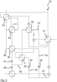
- the second sorption heat pump 27 according to the invention shown and the sorption cycle process according to the invention taking place therein correspond essentially to the first sorption heat pump 1.
- a flow of 6.7 kg/s of the solvent 29 absorbs a flow of 3.9 kg/s of the coolant 30 in the absorption unit 28 of the second sorption heat pump 27.
- the heat transfer medium 31 of the heat sink enters the absorption unit 28 at 60 °C.
- a flow of rich solution 32 emerging from the absorption unit 28 at 11.2 kg/s at a high pressure level of 45 bar at below 52 °C is expanded to a low pressure of 7.3 bar by the throttle valve 33 and heated to 38 °C in the expeller 34 with an output of 4130 kW.
- the heat transfer medium 35 of the heat source entering the expeller 34 at less than 40 °C is cooled to 35 °C.
- the flow of solvent 29 is pumped by the pump 37 and the flow of coolant 30 is pumped by the compressor 38 to a medium pressure level of 28 bar and conveyed into the absorption unit 28.
- the heat transfer medium 31 of the heat sink is first preheated to 78 °C in the medium-pressure absorber 39 with a heating output of 2047 kW and then further heated to the outlet temperature in the high-pressure absorber 40 with a heating output of 3464 kW.
- the second sorption heat pump 27 has an additional absorber 41 and a further solution heat exchanger 42.
- the high-pressure partial flow 44 of the refrigerant 30 emerging from the intermediate compressor 43 at 155 °C and the enriched solution 45 are split upstream of the high-pressure absorber 40 and guided in parallel through the high-pressure absorber 40 and the additional absorber 41 in two partial flows each; the respective emerging partial flows of the rich solution 32 are then brought together again.
- the partial flow of the enriched solution 45 in the additional absorber 41 is controlled by a throttle valve 46. Downstream of the intermediate pump 47, the flow of the enriched solution 45 emerging from the medium-pressure absorber 39 at 7.3 kg/s below 63 °C is first heated in the additional solution heat exchanger 42 by the rich solution 32 at the high-pressure level to 97 °C.
- the enriched solution 45 is then divided, controlled by two throttle valves 48 in partial flows of 3.65 kg/s each, heated in parallel in the intercooler 49 to 112 °C and in the additional absorber 41 to 107 °C, recombined and fed below 110 °C into the high pressure absorber 40 and the additional absorber 41.
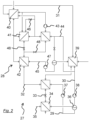
- the Figure 3 The third sorption heat pump 52 according to the invention shown and the sorption cycle process according to the invention taking place therein essentially correspond to the second sorption heat pump 27.
- the solvent 53 is divided into a first partial stream 54 and a second partial stream 55.
- the first partial stream 54 is pumped to the medium pressure level with a first pump 56 and conveyed to the medium pressure absorber 57. Before the medium pressure absorber 57, the first partial stream 54 of the solvent 53 gives up heat from the rich solution 59 in a solution heat exchanger 58 from the medium pressure absorber 57 and in the intercooler 60 from the high pressure partial stream 61.
- the second partial flow 55 is pumped to the high pressure level by a second pump 62 and conveyed to the high pressure absorber 63 and to the additional absorber 64. At the high pressure level, the second partial flow 55 absorbs heat from the rich solution 66 from the high pressure absorber 63 and the additional absorber 64.
- the rich solution 66 from the high-pressure absorber 63 and the additional absorber 64 is first expanded to the medium-pressure level in an intermediate throttle valve 67, combined with the rich solution 59 from the medium-pressure absorber and only then expanded to the low-pressure level in the throttle valve 68.
Landscapes
- Engineering & Computer Science (AREA)
- Physics & Mathematics (AREA)
- Mechanical Engineering (AREA)
- Thermal Sciences (AREA)
- General Engineering & Computer Science (AREA)
- Sorption Type Refrigeration Machines (AREA)
Abstract
Description
- Die Erfindung betrifft zunächst eine Sorptionswärmepumpe mit gasförmigem Kältemittel und flüssigem Lösungsmittel, mit einer angereicherten Lösung und einer reichen Lösung, die einphasige Mischungen des Lösungsmittels und des Kältemittels sind, mit einer Absorptionseinheit, in der ein erster Teilstrom des Lösungsmittels in einem Mitteldruckabsorber auf einem Mitteldruckniveau einen Mitteldruckteilstrom und ein zweiter Teilstrom in einem Hochdruckabsorber auf einem Hochdruckniveau einen Hochdruckteilstrom des Kältemittels absorbiert und dabei jeweils entstehende Wärme an eine Wärmesenke außerhalb der Sorptionswärmepumpe abgibt und mit einem Austreiber, in dem die reiche Lösung aus der Absorptionseinheit auf einem Niederdruckniveau aus einer Wärmequelle außerhalb der Sorptionswärmepumpe Wärme aufnimmt und dabei das Kältemittel austreibt. Die Erfindung betrifft weiterhin einen Sorptionskreisprozess in einer solchen Sorptionswärmepumpe.
- Eine solche Sorptionswärmepumpe und ein solcher Sorptionskreisprozess sind aus
EP 3 964 770 A1 bekannt. Dort wird vorgeschlagen, zunächst das Lösungsmittel und das Kältemittel vom dem Niederdruckniveau auf das Hochdruckniveau zu pumpen und zum Hochdruckabsorber zu fördern und vor dem Hochdruckabsorber den Mitteldruckteilstrom auszukoppeln und auf das Mitteldruckniveau zu entspannen, so dass das Lösungsmittel zunächst nur den verbleibenden Hochdruckteilstrom, und die entstandene angereicherte Lösung anschließend in dem Mitteldruckabsorber den Mitteldruckteilstrom absorbiert. - Der Erfindung liegt die Aufgabe zugrunde, den Energiebedarf zum Erreichen des Hochdruckniveaus zu vermindern.
- Ausgehend von der bekannten Sorptionswärmepume wird nach der Erfindung vorgeschlagen, einen Zwischenverdichter vorzusehen, der den Hochdruckteilstrom des Kältemittels von dem Mitteldruckniveau auf das Hochdruckniveau verdichtet und auf dem Hochdruckniveau in den Hochdruckabsorber fördert.
- In der erfindungsgemäßen Sorptionswärmepumpe ist die Menge des Kältemittels, das in gasförmigem Aggregatzustand auf das Hochdruckniveau verdichtet wird, gegenüber dem Stand der Technik um den Mitteldruckteilstrom vermindert. Der hierdurch eingesparte Energieaufwand ist höher als der zusätzliche Energieaufwand zum Pumpen des zusätzlichen Massenstroms der angereicherten Lösung auf das Hochdruckniveau.
- Vorzugsweise weist eine erfindungsgemäße Sorptionswärmepumpe eine Zwischenpumpe auf, die die im Mitteldruckabsorber entstandene angereicherte Lösung auf das Hochdruckniveau pumpt und auf dem Hochdruckniveau in den Hochdruckabsorber fördert. Der zusätzliche Energiebedarf zum Pumpen der um den Mitteldruckteilstrom angereicherten Lösung ist geringer als der Energiebedarf zum Verdichten des Mitteldruckteilstroms.
- Vorzugsweise weist eine erfindungsgemäße Sorptionswärmepumpe einen Zwischenkühler auf, in dem der Hochdruckteilstrom des Kältemittels auf dem Mitteldruckniveau Wärme abgibt. Viele Wärmepumpenanwendungen erfordern eine zweistufige Kältemittelverdichtung und Zwischenkühlung des Dampfes zwischen den Verdichtern, um das erforderliche Druckverhältnis zu erreichen, ohne dass der Kältemitteldampf während der Verdichtung unzulässig heiß wird.
- Insbesondere kann in dem Zwischenkühler die angereicherte Lösung auf dem Hochdruckniveau Wärme aufnehmen. In einer solchen erfindungsgemäßen Sorptionswärmepumpe kühlt die angereicherte Lösung den Hochdruckteilstrom und stellt die aufgenommene Wärme im Hochdruckabsorber für die Wärmesenke zur Verfügung.
- Vorzugsweise weist eine erfindungsgemäße Sorptionswärmepumpe einen Lösungswärmeübertrager auf, in dem einer der Teilströme aus der reichen Lösung auf dem Hochdruckniveau Wärme aufnimmt. Die aufgenommene Wärme steht dann im Mitteldruckabsorber für die Wärmesenke zur Verfügung. Insbesondere kann das Lösungsmittel auf dem Mitteldruckniveau die Wärme aufnehmen.
- Vorzugsweise weist eine erfindungsgemäße Sorptionswärmepumpe parallel zu dem Hochdruckabsorber einen Zusatzabsorber auf, in dem einer der Teilströme aus der reichen Lösung auf dem Hochdruckniveau Wärme aufnimmt. Wenn die Spreizung - also die Temperaturdifferenz zwischen Eintritt des Wärmeträgers in die und Austritt aus der Sorptionswärmepumpe - an der Wärmesenke deutlich größer ist als an der Wärmequelle, kann der Wärmeträger der Wärmesenke im Mitteldruckabsorber auf ein mittleres Temperaturniveau vorgewärmt werden. Die im Mitteldruckabsorber angereicherte Lösung wird so aber nahezu auf die Eintrittstemperatur der Wärmesenke abgekühlt. Vor Eintritt in den Hochdruckabsorber wird sie in einer solchen erfindungsgemäßen Sorptionswärmepumpe auf die Austrittstemperatur der Wärmesenke erwärmt. Insbesondere kann die angereicherte Lösung auf dem Hochdruckniveau die Wärme aufnehmen.
- Vorzugsweise sind in einer erfindungsgemäßen Sorptionswärmepumpe der Mitteldruckabsorber und/oder der Hochdruckabsorber Plattenwärmetauscher. Solche Absorber sind technisch einfach, wartungsarm und stehen kostengünstig in einer Vielzahl von Ausführungen am Markt zur Verfügung.
- Vorzugsweise weist eine erfindungsgemäße Sorptionswärmepumpe ein Drosselventil auf, das die reiche Lösung nach Austritt aus der Absorptionseinheit zum Eintritt in den Austreiber vom Hochdruck auf den Niederdruck entspannt, und eine Pumpe und einen Verdichter, die das Lösungsmittel und das Kältemittel nach Austritt aus dem Austreiber vom Niederdruck auf den Mitteldruck pumpen. Eine solche erfindungsgemäße Sorptionswärmepumpe nimmt Wärme auf einem niedrigen Temperaturniveau auf und gibt sie auf einem höheren Niveau wieder ab. Die reiche Lösung kühlt im Drosselventil ab und kann so die Niedertemperaturwärme aufnehmen. Das gasförmige Kältemittel und das flüssige Lösungsmittel werden getrennt der Absorptionseinheit zugeführt. Pumpen sind allgemein bekannte Vorrichtungen in der Kältetechnik und stehen in einer Vielzahl von Ausführungen preisgünstig zur Verfügung.
- Vorzugsweise ist in einer erfindungsgemäßen Sorptionswärmepumpe das Lösungsmittel Wasser und das Kältemittel Ammoniak. Wasser und Ammoniak sind natürliche Stoffe und haben sich in der Kältetechnik bewährt.
- Ausgehend von dem bekannten Sorptionskreisprozess wird nach der Erfindung vorgeschlagen, dass nur der Hochdruckteilstrom des Kältemittels von dem Mitteldruckniveau auf das Hochdruckniveau verdichtet wird. Der erfindungsgemäße Sorptionskreisprozess läuft in einer erfindungsgemäßen Sorptionswärmepumpe ab und zeichnet sich gleichermaßen durch deren vorstehend beschriebene Vorteile aus.
- Vorzugsweise wird in einem erfindungsgemäßen Sorptionskreisprozess ein Wärmeträger der Wärmesenke in zwei parallel geführte Teilströme geteilt und an einen ersten der Teilströme die beim Absorbieren des Mitteldruckteilstroms und an einen zweiten der Teilströme die beim Absorbieren des Hochdruckteilstroms entstehende Wärme abgegeben und die Teilströme werden anschließend wieder zusammengeführt. Bei sehr unterschiedlichen Spreizungen an der Wärmequelle und der Wärmesenke wird in einem solchen erfindungsgemäßen Sorptionskreisprozess ein möglichst großer Mitteldruckteilstrom auf dem Mitteldruckniveau absorbiert und die dabei entstehende Wärme an den Wärmeträger der Wärmesenke abgegeben, um dort beispielsweise Dampf zu erzeugen. Damit das relativ trockene Kältemittel sich nicht im Mitteldruckabsorber mit dem Lösungsmittel sättigt, wird dem Mitteldruckabsorber nur so viel Kältemittel zugeführt, wie absorbiert werden kann. Nur das verbleibende Kältemittel wird zum Hochdruckabsorber geleitet.
- Alternativ vorzugsweise wird in einem erfindungsgemäßen Sorptionskreisprozess an einen Wärmeträger der Wärmesenke zunächst die beim Absorbieren des Mitteldruckteilstroms und anschließend die beim Absorbieren des Hochdruckteilstroms entstehende Wärme abgegeben. Ist die Spreizung an der Wärmesenke viel größer als an der Wärmequelle, wird so der Wärmeträger der Wärmesenke im Mitteldruckabsorber vorgewärmt und erst im Hochdruckabsorber auf die gewünschte Ausgangstemperatur erwärmt.
- Vorzugsweise wird in einem erfindungsgemäßen Sorptionskreisprozess das Lösungsmittel in den ersten Teilstrom und den zweiten Teilstrom geteilt. Der erste Teilstrom muss dann nach Absorbieren des Mitteldruckteilstroms nicht mehr auf das Hochdruckniveau gepumpt werden.
- Die Erfindung wird nachfolgend anhand von Ausführungsbeispielen erläutert. Es zeigen
- Fig. 1
- eine erste erfindungsgemäße Sorptionswärmepumpe,
- Fig. 2
- eine zweite erfindungsgemäße Sorptionswärmepumpe und
- Fig. 3
- eine dritte erfindungsgemäße Sorptionswärmepumpe.
- Die in
Figur 1 gezeigte erste erfindungsgemäße Sorptionswärmepumpe 1 weist eine Absorptionseinheit 2, ein Drosselventil 3, einen Austreiber 4, einen Abscheider 5, einen Verdichter 6, eine Pumpe 7 sowie Rohrleitungen 8 auf, die die vorgenannten in dieser Reihenfolge zu einem kreisförmig geschlossenen System verbinden, wobei der Verdichter 6 in einem Kältemittelzweig 9 und die Pumpe 7 in einem parallel dazu verlaufenden Lösungsmittelzweig 10 vom Abscheider 5 zur Absorptionseinheit 2 angeordnet ist. - In einem Zyklus eines erfindungsgemäßen Sorptionskreisprozesses mit Ammoniak (NH3) als Kältemittel 11 in Wasser als Lösungsmittel 12 absorbiert in der Absorptionseinheit 2 ein Strom von 3,3 kg/s des Lösungsmittel 12 einen Strom von 3,2 kg/s des Kältemittels 11 und gibt an eine Wärmesenke Heizleistung ab.
- Mit 100 °C in die Absorptionseinheit 2 eintretendes Speisewasser als Wärmeträger 13 der Wärmesenke tritt mit 110 °C als Sattdampf aus der Absorptionseinheit 2 aus. Ein mit 87 °C auf einem Hochdruckniveau von 48 bar aus der Absorptionseinheit 2 mit 6,5 kg/s austretender Strom reicher Lösung 14 wird durch das Drosselventil 3 auf einen Niederdruck von 6 bar entspannt und im Austreiber 4 aus einer Wärmequelle mit einer Leistung von 2610 kW auf 64 °C erhitzt. Der mit 70 °C in den Austreiber 4 eintretende Wärmeträger 15 der Wärmequelle wird hierbei auf 30 °C abgekühlt. Aus dem nachfolgenden Abscheider 5 wird der Strom des Lösungsmittels 12 durch die Pumpe 7 und der Strom des Kältemittels 11 durch den Verdichter 6 jeweils auf ein Mitteldruckniveau von 22 bar gepumpt und in die Absorptionseinheit 2 gefördert.
- Die Absorptionseinheit 2 weist einen Mitteldruckabsorber 16 und einen Hochdruckabsorber 17 auf. Der Wärmeträger 13 der Wärmesenke wird vor Eintritt in den Mitteldruckabsorber 16 und den Hochdruckabsorber 17 zunächst in zwei Teilströme geteilt, der Mitteldruckabsorber 16 und der Hochdruckabsorber 17 werden von den Teilströmen parallel durchströmt und nach Austritt aus denselben werden die Teilströme wieder zusammengeführt. Das in die Absorptionseinheit 2 auf dem Mitteldruckniveau mit 160 °C eintretende Kältemittel 11 wird zunächst in einen Mitteldruckteilstrom 18 und einen Hochdruckteilstrom 19 geteilt. Im Mitteldruckabsorber 16 absorbiert ein erster Teilstrom 50 des Lösungsmittels 12 den Mitteldruckteilstrom 18 und gibt dabei eine Heizleistung von 303 kW an den Wärmeträger 13 der Wärmesenke ab.
- Die Absorptionseinheit 2 weist einen Mitteldruckabscheider 20, eine Zwischenpumpe 21, ein Drosselventil 22 und einen Zwischenverdichter 23 auf. Eine aus dem Mitteldruckabsorber 16 mit 110 °C austretende angereicherte Lösung 24 scheidet im Mitteldruckabscheider 20 zunächst nicht absorbiertes Kältemittel 11 ab und wird von der Zwischenpumpe 21 in einem zweiten Teilstrom 51 auf das Hochdruckniveau und mit 3,7 kg/s in den Hochdruckabsorber 17 gepumpt. Das Kältemittel 11 aus dem Mitteldruckabscheider 20 wird über das Drosselventil 22 mit dem Hochdruckteilstrom 19 zusammengeführt, mit diesem gemeinsam in dem Zwischenverdichter 23 gleichfalls auf das Hochdruckniveau verdichtet und hierbei von 84 °C auf 155 °C erhitzt und mit 2,8 kg/s in den Hochdruckabsorber 17 geführt.
- Die Absorptionseinheit 2 weist einen Zwischenkühler 25 und einen Lösungswärmeübertrager 26 auf. In dem Zwischenkühler 25 gibt der Hochdruckteilstrom 19 des Kältemittels 11 auf dem Mitteldruckniveau an die angereicherte Lösung 24 auf dem Hochdruckniveau Wärme ab und heizt diese auf 126 °C auf. In dem Lösungswärmeübertrager 26 nimmt das Lösungsmittel 12 auf dem Mitteldruckniveau Wärme aus der reichen Lösung 14 auf dem Hochdruckniveau auf.
- Der Austreiber 4, der Mitteldruckabsorber 16, der Hochdruckabsorber 17, der Zwischenkühler 25 und der Lösungswärmeübertrager 26 sind Plattenwärmetauscher.
- Die in
Figur 2 gezeigte zweite erfindungsgemäße Sorptionswärmepumpe 27 und der darin ablaufende erfindungsgemäße Sorptionskreisprozess entsprechen im Wesentlichen der ersten Sorptionswärmepumpe 1. In einem Zyklus absorbiert in der Absorptionseinheit 28 der zweiten Sorptionswärmepumpe 27 ein Strom von 6,7 kg/s des Lösungsmittels 29 einen Strom von 3,9 kg/s des Kältemittels 30. Der Wärmeträger 31 der Wärmesenke tritt mit 60 °C in die Absorptionseinheit 28 ein. Ein unter 52 °C auf einem Hochdruckniveau von 45 bar aus der Absorptionseinheit 28 mit 11,2 kg/s austretender Strom reicher Lösung 32 wird durch das Drosselventil 33 auf einen Niederdruck von 7,3 bar entspannt und in dem Austreiber 34 mit einer Leistung von 4130 kW auf 38 °C erhitzt. Der unter 40 °C in den Austreiber 34 eintretende Wärmeträger 35 der Wärmequelle wird hierbei auf 35 °C abgekühlt. Aus dem nachfolgenden Abscheider 36 wird der Strom des Lösungsmittels 29 durch die Pumpe 37 und der Strom des Kältemittels 30 durch den Verdichter 38 jeweils auf ein Mitteldruckniveau von 28 bar gepumpt und in die Absorptionseinheit 28 gefördert. - Abweichend von der ersten Sorptionswärmepumpe 1 wird der Wärmeträger 31 der Wärmesenke zunächst in dem Mitteldruckabsorber 39 mit einer Heizleistung von 2047 kW auf 78 °C vorgewärmt und anschließend in dem Hochdruckabsorber 40 mit einer Heizleistung von 3464 kW weiter auf die Austrittstemperatur erhitzt. Zusätzlich weist die zweite Sorptionswärmepumpe 27 einen Zusatzabsorber 41 und einen weiteren Lösungswärmeübertrager 42 auf.
- Der mit 155 °C aus dem Zwischenverdichter 43 austretende Hochdruckteilstrom 44 des Kältemittels 30 und die angereicherte Lösung 45 werden vor dem Hochdruckabsorber 40 geteilt und in je zwei Teilströmen parallel durch den Hochdruckabsorber 40 und den Zusatzabsorber 41 geführt, die jeweils austretenden Teilströme der reichen Lösung 32 werden anschließend wieder zusammengeführt. Der Teilstrom der angereicherten Lösung 45 im Zusatzabsorber 41 wird durch ein Drosselventil 46 gesteuert. Hinter der Zwischenpumpe 47 wird der aus dem Mitteldruckabsorber 39 mit 7,3 kg/s unter 63 °C austretende Strom der angereicherten Lösung 45 zunächst in dem weiteren Lösungswärmeübertrager 42 von der reichen 32 Lösung auf dem Hochdruckniveau auf 97 °C erhitzt. Die angereicherte Lösung 45 wird dann geteilt, durch zwei Drosselventile 48 gesteuert in Teilströmen mit je 3,65 kg/s parallel im Zwischenkühler 49 auf 112 °C und im Zusatzabsorber 41 auf 107 °C erhitzt, wieder zusammengeführt und unter 110 °C in den Hochdruckabsorber 40 und den Zusatzabsorber 41 geführt.
- Die in
Figur 3 gezeigte dritte erfindungsgemäße Sorptionswärmepumpe 52 und der darin ablaufende erfindungsgemäße Sorptionskreisprozess entsprechen im Wesentlichen der zweiten Sorptionswärmepumpe 27. Abweichend wird das Lösungsmittel 53 in einen ersten Teilstrom 54 und einen zweiten Teilstrom 55 geteilt. - Der erste Teilstrom 54 wird mit einer ersten Pumpe 56 auf das Mitteldruckniveau gepumpt und zum Mitteldruckabsorber 57 gefördert. Vor dem Mitteldruckabsorber 57 gibt der erste Teilstrom 54 des Lösungsmittels 53 in einem Lösungswärmeübertrager 58 Wärme aus der reichen Lösung 59 aus dem Mitteldruckabsorber 57 und im Zwischenkühler 60 aus den Hochdruckteilstrom 61 auf.
- Der zweite Teilstrom 55 wird mit einer zweiten Pumpe 62 auf das Hochdruckniveau gepumpt und zum Hochdruckabsorber 63 und zum Zusatzabsorber 64 gefördert. Auf dem Hochdruckniveau nimmt der zweite Teilstrom 55 in einem weiteren Lösungswärmeübertrager 65 Wärme aus der reichen Lösung 66 aus dem Hochdruckabsorber 63 und dem Zusatzabsorber 64 auf.
- Die reiche Lösung 66 aus dem Hochdruckabsorber 63 und dem Zusatzabsorber 64 wird zunächst in einem Zwischendrosselventil 67 auf das Mitteldruckniveau entspannt, mit der reichen Lösung 59 aus dem Mitteldruckabsorber zusammengeführt und erst dann in dem Drosselventil 68 auf das Niederdruckniveau entspannt.
-
- 1
- Sorptionswärmepumpe
- 2
- Absorptionseinheit
- 3
- Drosselventil
- 4
- Austreiber
- 5
- Abscheider
- 6
- Verdichter
- 7
- Pumpe
- 8
- Rohrleitung
- 9
- Kältemittelzweig
- 10
- Lösungsmittelzweig
- 11
- Kältemittel
- 12
- Lösungsmittel
- 13
- Wärmeträger der Wärmesenke
- 14
- reiche Lösung
- 15
- Wärmeträger der Wärmequelle
- 16
- Mitteldruckabsorber
- 17
- Hochdruckabsorber
- 18
- Mitteldruckteilstrom
- 19
- Hochdruckteilstrom
- 20
- Mitteldruckabscheider
- 21
- Zwischenpumpe
- 22
- Drosselventil
- 23
- Zwischenverdichter
- 24
- angereicherte Lösung
- 25
- Zwischenkühler
- 26
- Lösungswärmeübertrager
- 27
- Sorptionswärmepumpe
- 28
- Absorptionseinheit
- 29
- Lösungsmittel
- 30
- Kältemittel
- 31
- Wärmeträger der Wärmesenke
- 32
- reiche Lösung
- 33
- Drosselventil
- 34
- Austreiber
- 35
- Wärmeträger der Wärmequelle
- 36
- Abscheider
- 37
- Pumpe
- 38
- Verdichter
- 39
- Mitteldruckabsorber
- 40
- Hochdruckabsorber
- 41
- Zusatzabsorber
- 42
- weiterer Lösungswärmeübertrager
- 43
- Zwischenverdichter
- 44
- Hochdruckteilstrom
- 45
- angereicherte Lösung
- 46
- Drosselventil
- 47
- Zwischenpumpe
- 48
- Drosselventil
- 49
- Zwischenkühler
- 50
- erster Teilstrom des Lösungsmittels
- 51
- zweiter Teilstrom des Lösungsmittels
- 52
- Sorptionswärmepumpe
- 53
- Lösungsmittel
- 54
- erster Teilstrom des Lösungsmittels
- 55
- zweiter Teilstrom des Lösungsmittels
- 56
- erste Pumpe
- 57
- Mitteldruckabsorber
- 58
- Lösungswärmeübertrager
- 59
- reiche Lösung
- 60
- Zwischenkühler
- 61
- Hochdruckteilstrom
- 62
- zweite Pumpe
- 63
- Hochdruckabsorber
- 64
- Zusatzabsorber
- 65
- Lösungswärmeübertrager
- 66
- reiche Lösung
- 67
- Zwischendrosselventil
- 68
- Drosselventil
Claims (12)
- Sorptionswärmepumpe (1, 27, 52)• mit gasförmigem Kältemittel (11, 30) und flüssigem Lösungsmittel (12, 29, 53),• mit einer angereicherten Lösung (24, 45) und einer reichen Lösung (14, 32, 59, 66), die einphasige Mischungen des Lösungsmittels (12, 29, 53) und des Kältemittels (11, 30) sind,• mit einer Absorptionseinheit (2, 28), in der ein erster Teilstrom (50, 54) des Lösungsmittels (12, 29, 53) in einem Mitteldruckabsorber (16, 39, 57) auf einem Mitteldruckniveau einen Mitteldruckteilstrom (18) und ein zweiter Teilstrom (51, 55) in einem Hochdruckabsorber (17, 40 63) auf einem Hochdruckniveau einen Hochdruckteilstrom (19, 44) des Kältemittels (11, 30) absorbiert und dabei jeweils entstehende Wärme an eine Wärmesenke außerhalb der Sorptionswärmepumpe (1, 27, 52) abgibt und• mit einem Austreiber (4, 34), in dem die reiche Lösung (14, 32) aus der Absorptionseinheit (2, 28) auf einem Niederdruckniveau aus einer Wärmequelle außerhalb der Sorptionswärmepumpe (1, 27, 52) Wärme aufnimmt und dabei das Kältemittel (11, 30) austreibt,gekennzeichnet durch einen Zwischenverdichter (23, 43), der den Hochdruckteilstrom (19, 44) des Kältemittels (11, 30) von dem Mitteldruckniveau auf das Hochdruckniveau verdichtet und auf dem Hochdruckniveau in den Hochdruckabsorber (17, 40 63) fördert.
- Sorptionswärmepumpe (1, 27, 52) nach dem vorgenannten Anspruch, gekennzeichnet durch eine Zwischenpumpe (21, 47), die die im Mitteldruckabsorber (16, 39, 57) entstandene angereicherte Lösung (24, 45) auf das Hochdruckniveau pumpt und auf dem Hochdruckniveau in den Hochdruckabsorber (17, 40, 63) fördert.
- Sorptionswärmepumpe (1, 27, 52) nach einem der vorgenannten Ansprüche, gekennzeichnet durch einen Zwischenkühler (25, 49, 60), in dem der Hochdruckteilstrom (19, 44) des Kältemittels (11, 30) auf dem Mitteldruckniveau Wärme insbesondere an die angereicherte Lösung (24, 45) auf dem Hochdruckniveau abgibt.
- Sorptionswärmepumpe (1, 27, 52) nach einem der vorgenannten Ansprüche, gekennzeichnet durch einen Lösungswärmeübertrager (26, 58, 65), in dem einer der Teilströme (50, 51, 54, 55) aus der reichen Lösung (14, 32, 66) auf dem Hochdruckniveau Wärme aufnimmt.
- Sorptionswärmepumpe (27, 52) nach einem der vorgenannten Ansprüche, gekennzeichnet durch einen parallel zu dem Hochdruckabsorber (17, 40, 63) angeordneten Zusatzabsorber (41 64), in dem einer der Teilströme (50, 51, 54, 55) auf dem Hochdruckniveau Wärme aufnimmt.
- Sorptionswärmepumpe (1, 27, 52) nach einem der vorgenannten Ansprüche, dadurch gekennzeichnet, dass der Mitteldruckabsorber (16, 39 57) und/oder der Hochdruckabsorber (17, 40, 63) Plattenwärmetauscher sind.
- Sorptionswärmepumpe (1, 27) nach einem der vorgenannten Ansprüche, gekennzeichnet durch ein Drosselventil (3, 33, 68), das die reiche Lösung (14, 32) nach Austritt aus der Absorptionseinheit (2, 28) zum Eintritt in den Austreiber (4, 34) vom Hochdruck auf den Niederdruck entspannt, und eine Pumpe (7, 37, 56) und einen Verdichter (6, 38), die das Lösungsmittel (12, 29) und das Kältemittel (11, 30) nach Austritt aus dem Austreiber (4, 34) vom Niederdruck auf den Mitteldruck pumpen.
- Sorptionswärmepumpe (1, 27, 52) nach einem der vorgenannten Ansprüche, dadurch gekennzeichnet, dass das Lösungsmittel (12, 29, 53) Wasser und das Kältemittel (11, 30) Ammoniak ist.
- Sorptionskreisprozess• mit gasförmigem Kältemittel (11, 30) und flüssigem Lösungsmittel (12, 29, 53),• mit einer angereicherten Lösung (24, 45) und einer reichen Lösung (14, 32, 59, 66), die einphasige Mischungen des Lösungsmittels (12, 29, 53) und des Kältemittels (11, 30) sind,• wobei ein erster Teilstrom (50, 54) des Lösungsmittels (12, 29, 53) auf einem Mitteldruckniveau einen Mitteldruckteilstrom (18) und ein zweiter Teilstrom (51, 55) auf einem Hochdruckniveau einen Hochdruckteilstrom (19, 44) des Kältemittels (11, 30) absorbiert und dabei jeweils entstehende Wärme an eine Wärmesenke außerhalb des Sorptionskreisprozesses abgibt und• wobei die nach Absorption des Kältemittels (11, 30) entstandene reiche Lösung (14, 32, 59, 66) auf einem Niederdruckniveau aus einer Wärmequelle außerhalb des Sorptionskreisprozesses Wärme aufnimmt und dabei das Kältemittel (11, 30) austreibt,dadurch gekennzeichnet, dass nur der Hochdruckteilstrom (19, 44) des Kältemittels (11, 30) von dem Mitteldruckniveau auf das Hochdruckniveau verdichtet wird.
- Sorptionskreisprozess nach dem vorgenannten Anspruch, dadurch gekennzeichnet, dass ein Wärmeträger (13) der Wärmesenke in zwei parallel geführte Teilströme geteilt und an einen ersten der Teilströme des Wärmeträgers (13) die beim Absorbieren des Mitteldruckteilstroms (18) und an einen zweiten der Teilströme des Wärmeträgers (13) die beim Absorbieren des Hochdruckteilstroms (19, 44) entstehende Wärme abgegeben wird und die Teilströme des Wärmeträgers (13) anschließend wieder zusammengeführt werden.
- Sorptionskreisprozess nach Anspruch 9, dadurch gekennzeichnet, dass an einen Wärmeträger (31) der Wärmesenke zunächst die beim Absorbieren des Mitteldruckteilstroms und anschließend die beim Absorbieren des Hochdruckteilstroms (44) entstehende Wärme abgegeben wird.
- Sorptionskreisprozess nach einem der Ansprüche 9 bis 11, dadurch gekennzeichnet, dass das Lösungsmittel (53) in den ersten Teilstrom (54) und den zweiten Teilstrom (55) geteilt wird.
Priority Applications (4)
| Application Number | Priority Date | Filing Date | Title |
|---|---|---|---|
| EP23159593.5A EP4425072B1 (de) | 2023-03-02 | 2023-03-02 | Sorptionswärmepumpe und -kreisprozess |
| CN202410220449.2A CN118582867A (zh) | 2023-03-02 | 2024-02-28 | 吸收式热泵和吸收循环 |
| JP2024031335A JP2024124390A (ja) | 2023-03-02 | 2024-03-01 | 収着式ヒートポンプおよび収着式循環法 |
| US18/593,707 US20240410626A1 (en) | 2023-03-02 | 2024-03-01 | Sorption heat pump and sorption cycle |
Applications Claiming Priority (1)
| Application Number | Priority Date | Filing Date | Title |
|---|---|---|---|
| EP23159593.5A EP4425072B1 (de) | 2023-03-02 | 2023-03-02 | Sorptionswärmepumpe und -kreisprozess |
Publications (3)
| Publication Number | Publication Date |
|---|---|
| EP4425072A1 true EP4425072A1 (de) | 2024-09-04 |
| EP4425072C0 EP4425072C0 (de) | 2024-12-11 |
| EP4425072B1 EP4425072B1 (de) | 2024-12-11 |
Family
ID=85415217
Family Applications (1)
| Application Number | Title | Priority Date | Filing Date |
|---|---|---|---|
| EP23159593.5A Active EP4425072B1 (de) | 2023-03-02 | 2023-03-02 | Sorptionswärmepumpe und -kreisprozess |
Country Status (4)
| Country | Link |
|---|---|
| US (1) | US20240410626A1 (de) |
| EP (1) | EP4425072B1 (de) |
| JP (1) | JP2024124390A (de) |
| CN (1) | CN118582867A (de) |
Cited By (2)
| Publication number | Priority date | Publication date | Assignee | Title |
|---|---|---|---|---|
| CN120907261A (zh) * | 2025-10-10 | 2025-11-07 | 安徽普泛能源技术有限公司 | 一种回收高压流体能量用于导液降温洗涤的机组及工艺 |
| EP4745486A1 (de) | 2024-11-13 | 2026-05-20 | AGO Technologie GmbH | Sorptionswärmepumpe und -kreisprozess |
Citations (3)
| Publication number | Priority date | Publication date | Assignee | Title |
|---|---|---|---|---|
| EP3540333A1 (de) * | 2018-03-15 | 2019-09-18 | AGO AG Energie + Anlagen | Sorptionswärmepumpe und sorptionskreisprozess |
| EP3540332A1 (de) * | 2018-03-15 | 2019-09-18 | AGO AG Energie + Anlagen | Sorptionswärmepumpe und sorptionskreisprozess |
| EP3964770A1 (de) | 2020-09-08 | 2022-03-09 | AGO GmbH Energie + Anlagen | Sorptionswärmepumpe und sorptionskreisprozess |
Family Cites Families (7)
| Publication number | Priority date | Publication date | Assignee | Title |
|---|---|---|---|---|
| JP2001165522A (ja) * | 1999-12-06 | 2001-06-22 | Minoru Morita | 吸収式ヒートポンプおよびそのヒートポンプ装置 |
| CN101995112B (zh) * | 2010-11-24 | 2012-07-18 | 浙江大学 | 一种高效gax吸收式制冷装置 |
| GR20120100123A (el) * | 2012-03-01 | 2013-10-15 | Βασιλειος Ευθυμιου Στυλιαρας | Αντλια θερμοτητας υψηλης αποδοσης με απορροφηση και μεταβολη περιεκτικοτητας διαλυματος |
| CN104214988B (zh) * | 2014-09-03 | 2016-05-04 | 中国科学院工程热物理研究所 | 一种双温热源吸收式制冷系统 |
| EP3236178B1 (de) * | 2016-04-22 | 2020-08-12 | AGO AG Energie + Anlagen | Sorptionswärmepumpe und sorptionskreisprozess |
| EP3355002B1 (de) * | 2017-01-26 | 2019-05-22 | AGO AG Energie + Anlagen | Sorptionswärmepumpe und sorptionskreisprozess |
| EP3954950B1 (de) * | 2020-08-10 | 2025-04-09 | AGO Technologie GmbH | Sorptionswärmepumpe und sorptionskreisprozess |
-
2023
- 2023-03-02 EP EP23159593.5A patent/EP4425072B1/de active Active
-
2024
- 2024-02-28 CN CN202410220449.2A patent/CN118582867A/zh active Pending
- 2024-03-01 US US18/593,707 patent/US20240410626A1/en not_active Abandoned
- 2024-03-01 JP JP2024031335A patent/JP2024124390A/ja active Pending
Patent Citations (3)
| Publication number | Priority date | Publication date | Assignee | Title |
|---|---|---|---|---|
| EP3540333A1 (de) * | 2018-03-15 | 2019-09-18 | AGO AG Energie + Anlagen | Sorptionswärmepumpe und sorptionskreisprozess |
| EP3540332A1 (de) * | 2018-03-15 | 2019-09-18 | AGO AG Energie + Anlagen | Sorptionswärmepumpe und sorptionskreisprozess |
| EP3964770A1 (de) | 2020-09-08 | 2022-03-09 | AGO GmbH Energie + Anlagen | Sorptionswärmepumpe und sorptionskreisprozess |
Cited By (2)
| Publication number | Priority date | Publication date | Assignee | Title |
|---|---|---|---|---|
| EP4745486A1 (de) | 2024-11-13 | 2026-05-20 | AGO Technologie GmbH | Sorptionswärmepumpe und -kreisprozess |
| CN120907261A (zh) * | 2025-10-10 | 2025-11-07 | 安徽普泛能源技术有限公司 | 一种回收高压流体能量用于导液降温洗涤的机组及工艺 |
Also Published As
| Publication number | Publication date |
|---|---|
| EP4425072C0 (de) | 2024-12-11 |
| EP4425072B1 (de) | 2024-12-11 |
| JP2024124390A (ja) | 2024-09-12 |
| US20240410626A1 (en) | 2024-12-12 |
| CN118582867A (zh) | 2024-09-03 |
Similar Documents
| Publication | Publication Date | Title |
|---|---|---|
| EP4425072B1 (de) | Sorptionswärmepumpe und -kreisprozess | |
| EP3236178B1 (de) | Sorptionswärmepumpe und sorptionskreisprozess | |
| DE60314911T2 (de) | Betriebsverfahren eines Kühlsystems | |
| EP3540332B1 (de) | Sorptionswärmepumpe und sorptionskreisprozess | |
| EP0592059A1 (de) | Verfahren und Vorrichtung zum Verdichten eines gasförmigen Mediums | |
| DE102006035784A1 (de) | Kälteanlage für transkritischen Betrieb mit Economiser und Niederdruck-Sammler | |
| EP3540333A1 (de) | Sorptionswärmepumpe und sorptionskreisprozess | |
| EP3964770A1 (de) | Sorptionswärmepumpe und sorptionskreisprozess | |
| EP4491970B1 (de) | Sorptionswärmepumpe und -kreisprozess | |
| EP3355002B1 (de) | Sorptionswärmepumpe und sorptionskreisprozess | |
| DE102008011255A1 (de) | Ejektorzyklus mit einphasigem Strahl | |
| DE102024123715A1 (de) | Wärmepumpenvorrichtung zur Dampf- und Wärmeerzeugung | |
| DE102017100281B3 (de) | Absorptionsprozess und -maschine zur Nutzung von industrieller Abwärme | |
| EP3540334A1 (de) | Wärmetransformator und wärmetransformationsprozess | |
| DE19755484A1 (de) | Verfahren zur Kälteerzeugung im Temperaturbereich von 50,1 bis 63 Kelvin und Vorrichtung zur Durchführung dieses Verfahrens | |
| DE102009039326A1 (de) | Wärmepumpe | |
| DE102012017314A1 (de) | System zur Wirkungsgradsteigerung von zwei- oder mehrstufigen Verdichteranordnungen | |
| EP4092357B1 (de) | Sorptionswärmepumpe und sorptionskreisprozess | |
| WO2004010003A2 (de) | Verfahren zur verdichtung des arbeitsfluids beim wasser-dampf-kombi-prozess | |
| EP3623725A1 (de) | Absorptionsmaschine und sorptionskreisprozess | |
| EP3775518B1 (de) | Erweiterter gasturbinenprozess mit erdgasregasifizierung | |
| DE102012004801A1 (de) | Anordnung für eine Wärmepumpe mit Schraubenverdichter | |
| DE10017828A1 (de) | Verfahren zum Betreiben einer Sorptionskälteanlage | |
| EP1596141B1 (de) | Arbeitsverfahren einer Sorptionsanlage | |
| EP4261478A1 (de) | Sorptionswärmepumpe und sorptionskreisprozess |
Legal Events
| Date | Code | Title | Description |
|---|---|---|---|
| STAA | Information on the status of an ep patent application or granted ep patent |
Free format text: STATUS: EXAMINATION IS IN PROGRESS |
|
| PUAI | Public reference made under article 153(3) epc to a published international application that has entered the european phase |
Free format text: ORIGINAL CODE: 0009012 |
|
| 17P | Request for examination filed |
Effective date: 20230925 |
|
| AK | Designated contracting states |
Kind code of ref document: A1 Designated state(s): AL AT BE BG CH CY CZ DE DK EE ES FI FR GB GR HR HU IE IS IT LI LT LU LV MC ME MK MT NL NO PL PT RO RS SE SI SK SM TR |
|
| GRAP | Despatch of communication of intention to grant a patent |
Free format text: ORIGINAL CODE: EPIDOSNIGR1 |
|
| STAA | Information on the status of an ep patent application or granted ep patent |
Free format text: STATUS: GRANT OF PATENT IS INTENDED |
|
| INTG | Intention to grant announced |
Effective date: 20240918 |
|
| RAP1 | Party data changed (applicant data changed or rights of an application transferred) |
Owner name: AGO TECHNOLOGIE GMBH |
|
| GRAS | Grant fee paid |
Free format text: ORIGINAL CODE: EPIDOSNIGR3 |
|
| GRAA | (expected) grant |
Free format text: ORIGINAL CODE: 0009210 |
|
| STAA | Information on the status of an ep patent application or granted ep patent |
Free format text: STATUS: THE PATENT HAS BEEN GRANTED |
|
| AK | Designated contracting states |
Kind code of ref document: B1 Designated state(s): AL AT BE BG CH CY CZ DE DK EE ES FI FR GB GR HR HU IE IS IT LI LT LU LV MC ME MK MT NL NO PL PT RO RS SE SI SK SM TR |
|
| RBV | Designated contracting states (corrected) |
Designated state(s): AL AT BE BG CH CY CZ DE DK EE ES FI FR GB GR HR HU IE IS IT LI LT LU LV MC ME MK MT NL NO PL PT RO RS SE SI SK SM TR |
|
| REG | Reference to a national code |
Ref country code: GB Ref legal event code: FG4D Free format text: NOT ENGLISH |
|
| REG | Reference to a national code |
Ref country code: CH Ref legal event code: EP |
|
| REG | Reference to a national code |
Ref country code: IE Ref legal event code: FG4D Free format text: LANGUAGE OF EP DOCUMENT: GERMAN |
|
| REG | Reference to a national code |
Ref country code: DE Ref legal event code: R096 Ref document number: 502023000377 Country of ref document: DE |
|
| U01 | Request for unitary effect filed |
Effective date: 20241218 |
|
| U07 | Unitary effect registered |
Designated state(s): AT BE BG DE DK EE FI FR IT LT LU LV MT NL PT RO SE SI Effective date: 20250114 |
|
| U20 | Renewal fee for the european patent with unitary effect paid |
Year of fee payment: 3 Effective date: 20250225 |
|
| PG25 | Lapsed in a contracting state [announced via postgrant information from national office to epo] |
Ref country code: HR Free format text: LAPSE BECAUSE OF FAILURE TO SUBMIT A TRANSLATION OF THE DESCRIPTION OR TO PAY THE FEE WITHIN THE PRESCRIBED TIME-LIMIT Effective date: 20241211 |
|
| PG25 | Lapsed in a contracting state [announced via postgrant information from national office to epo] |
Ref country code: ES Free format text: LAPSE BECAUSE OF FAILURE TO SUBMIT A TRANSLATION OF THE DESCRIPTION OR TO PAY THE FEE WITHIN THE PRESCRIBED TIME-LIMIT Effective date: 20241211 |
|
| PG25 | Lapsed in a contracting state [announced via postgrant information from national office to epo] |
Ref country code: NO Free format text: LAPSE BECAUSE OF FAILURE TO SUBMIT A TRANSLATION OF THE DESCRIPTION OR TO PAY THE FEE WITHIN THE PRESCRIBED TIME-LIMIT Effective date: 20250311 |
|
| PG25 | Lapsed in a contracting state [announced via postgrant information from national office to epo] |
Ref country code: GR Free format text: LAPSE BECAUSE OF FAILURE TO SUBMIT A TRANSLATION OF THE DESCRIPTION OR TO PAY THE FEE WITHIN THE PRESCRIBED TIME-LIMIT Effective date: 20250312 |
|
| PG25 | Lapsed in a contracting state [announced via postgrant information from national office to epo] |
Ref country code: RS Free format text: LAPSE BECAUSE OF FAILURE TO SUBMIT A TRANSLATION OF THE DESCRIPTION OR TO PAY THE FEE WITHIN THE PRESCRIBED TIME-LIMIT Effective date: 20250311 |
|
| PG25 | Lapsed in a contracting state [announced via postgrant information from national office to epo] |
Ref country code: SM Free format text: LAPSE BECAUSE OF FAILURE TO SUBMIT A TRANSLATION OF THE DESCRIPTION OR TO PAY THE FEE WITHIN THE PRESCRIBED TIME-LIMIT Effective date: 20241211 |
|
| PG25 | Lapsed in a contracting state [announced via postgrant information from national office to epo] |
Ref country code: PL Free format text: LAPSE BECAUSE OF FAILURE TO SUBMIT A TRANSLATION OF THE DESCRIPTION OR TO PAY THE FEE WITHIN THE PRESCRIBED TIME-LIMIT Effective date: 20241211 |
|
| PG25 | Lapsed in a contracting state [announced via postgrant information from national office to epo] |
Ref country code: IS Free format text: LAPSE BECAUSE OF FAILURE TO SUBMIT A TRANSLATION OF THE DESCRIPTION OR TO PAY THE FEE WITHIN THE PRESCRIBED TIME-LIMIT Effective date: 20250411 |
|
| PG25 | Lapsed in a contracting state [announced via postgrant information from national office to epo] |
Ref country code: SK Free format text: LAPSE BECAUSE OF FAILURE TO SUBMIT A TRANSLATION OF THE DESCRIPTION OR TO PAY THE FEE WITHIN THE PRESCRIBED TIME-LIMIT Effective date: 20241211 |
|
| PG25 | Lapsed in a contracting state [announced via postgrant information from national office to epo] |
Ref country code: CZ Free format text: LAPSE BECAUSE OF FAILURE TO SUBMIT A TRANSLATION OF THE DESCRIPTION OR TO PAY THE FEE WITHIN THE PRESCRIBED TIME-LIMIT Effective date: 20241211 |
|
| PG25 | Lapsed in a contracting state [announced via postgrant information from national office to epo] |
Ref country code: MC Free format text: LAPSE BECAUSE OF FAILURE TO SUBMIT A TRANSLATION OF THE DESCRIPTION OR TO PAY THE FEE WITHIN THE PRESCRIBED TIME-LIMIT Effective date: 20241211 |
|
| PLBE | No opposition filed within time limit |
Free format text: ORIGINAL CODE: 0009261 |
|
| STAA | Information on the status of an ep patent application or granted ep patent |
Free format text: STATUS: NO OPPOSITION FILED WITHIN TIME LIMIT |
|
| 26N | No opposition filed |
Effective date: 20250912 |
|
| PG25 | Lapsed in a contracting state [announced via postgrant information from national office to epo] |
Ref country code: IE Free format text: LAPSE BECAUSE OF NON-PAYMENT OF DUE FEES Effective date: 20250302 |
|
| U20 | Renewal fee for the european patent with unitary effect paid |
Year of fee payment: 4 Effective date: 20260108 |
|
| PG25 | Lapsed in a contracting state [announced via postgrant information from national office to epo] |
Ref country code: CY Free format text: LAPSE BECAUSE OF FAILURE TO SUBMIT A TRANSLATION OF THE DESCRIPTION OR TO PAY THE FEE WITHIN THE PRESCRIBED TIME-LIMIT Effective date: 20241211 |
|
| PG25 | Lapsed in a contracting state [announced via postgrant information from national office to epo] |
Ref country code: TR Free format text: LAPSE BECAUSE OF FAILURE TO SUBMIT A TRANSLATION OF THE DESCRIPTION OR TO PAY THE FEE WITHIN THE PRESCRIBED TIME-LIMIT Effective date: 20241211 |