EP4424985A1 - Hydraulischer transformator - Google Patents
Hydraulischer transformator Download PDFInfo
- Publication number
- EP4424985A1 EP4424985A1 EP23159986.1A EP23159986A EP4424985A1 EP 4424985 A1 EP4424985 A1 EP 4424985A1 EP 23159986 A EP23159986 A EP 23159986A EP 4424985 A1 EP4424985 A1 EP 4424985A1
- Authority
- EP
- European Patent Office
- Prior art keywords
- face plate
- barrel member
- back side
- housing
- hydraulic transformer
- Prior art date
- Legal status (The legal status is an assumption and is not a legal conclusion. Google has not performed a legal analysis and makes no representation as to the accuracy of the status listed.)
- Granted
Links
Images


Classifications
-
- F—MECHANICAL ENGINEERING; LIGHTING; HEATING; WEAPONS; BLASTING
- F04—POSITIVE - DISPLACEMENT MACHINES FOR LIQUIDS; PUMPS FOR LIQUIDS OR ELASTIC FLUIDS
- F04B—POSITIVE-DISPLACEMENT MACHINES FOR LIQUIDS; PUMPS
- F04B1/00—Multi-cylinder machines or pumps characterised by number or arrangement of cylinders
- F04B1/12—Multi-cylinder machines or pumps characterised by number or arrangement of cylinders having cylinder axes coaxial with, or parallel or inclined to, main shaft axis
- F04B1/20—Multi-cylinder machines or pumps characterised by number or arrangement of cylinders having cylinder axes coaxial with, or parallel or inclined to, main shaft axis having rotary cylinder block
-
- F—MECHANICAL ENGINEERING; LIGHTING; HEATING; WEAPONS; BLASTING
- F01—MACHINES OR ENGINES IN GENERAL; ENGINE PLANTS IN GENERAL; STEAM ENGINES
- F01B—MACHINES OR ENGINES, IN GENERAL OR OF POSITIVE-DISPLACEMENT TYPE, e.g. STEAM ENGINES
- F01B3/00—Reciprocating-piston machines or engines with cylinder axes coaxial with, or parallel or inclined to, main shaft axis
- F01B3/0032—Reciprocating-piston machines or engines with cylinder axes coaxial with, or parallel or inclined to, main shaft axis having rotary cylinder block
-
- F—MECHANICAL ENGINEERING; LIGHTING; HEATING; WEAPONS; BLASTING
- F03—MACHINES OR ENGINES FOR LIQUIDS; WIND, SPRING, OR WEIGHT MOTORS; PRODUCING MECHANICAL POWER OR A REACTIVE PROPULSIVE THRUST, NOT OTHERWISE PROVIDED FOR
- F03C—POSITIVE-DISPLACEMENT ENGINES DRIVEN BY LIQUIDS
- F03C1/00—Reciprocating-piston liquid engines
- F03C1/02—Reciprocating-piston liquid engines with multiple-cylinders, characterised by the number or arrangement of cylinders
- F03C1/06—Reciprocating-piston liquid engines with multiple-cylinders, characterised by the number or arrangement of cylinders with cylinder axes generally coaxial with, or parallel or inclined to, main shaft axis
- F03C1/0636—Reciprocating-piston liquid engines with multiple-cylinders, characterised by the number or arrangement of cylinders with cylinder axes generally coaxial with, or parallel or inclined to, main shaft axis having rotary cylinder block
- F03C1/0639—Reciprocating-piston liquid engines with multiple-cylinders, characterised by the number or arrangement of cylinders with cylinder axes generally coaxial with, or parallel or inclined to, main shaft axis having rotary cylinder block having two or more sets of cylinders or pistons
- F03C1/0642—Reciprocating-piston liquid engines with multiple-cylinders, characterised by the number or arrangement of cylinders with cylinder axes generally coaxial with, or parallel or inclined to, main shaft axis having rotary cylinder block having two or more sets of cylinders or pistons inclined on main shaft axis
-
- F—MECHANICAL ENGINEERING; LIGHTING; HEATING; WEAPONS; BLASTING
- F03—MACHINES OR ENGINES FOR LIQUIDS; WIND, SPRING, OR WEIGHT MOTORS; PRODUCING MECHANICAL POWER OR A REACTIVE PROPULSIVE THRUST, NOT OTHERWISE PROVIDED FOR
- F03C—POSITIVE-DISPLACEMENT ENGINES DRIVEN BY LIQUIDS
- F03C1/00—Reciprocating-piston liquid engines
- F03C1/02—Reciprocating-piston liquid engines with multiple-cylinders, characterised by the number or arrangement of cylinders
- F03C1/06—Reciprocating-piston liquid engines with multiple-cylinders, characterised by the number or arrangement of cylinders with cylinder axes generally coaxial with, or parallel or inclined to, main shaft axis
- F03C1/0636—Reciprocating-piston liquid engines with multiple-cylinders, characterised by the number or arrangement of cylinders with cylinder axes generally coaxial with, or parallel or inclined to, main shaft axis having rotary cylinder block
- F03C1/0644—Component parts
- F03C1/0647—Particularities in the contacting area between cylinder barrel and valve plate
-
- F—MECHANICAL ENGINEERING; LIGHTING; HEATING; WEAPONS; BLASTING
- F03—MACHINES OR ENGINES FOR LIQUIDS; WIND, SPRING, OR WEIGHT MOTORS; PRODUCING MECHANICAL POWER OR A REACTIVE PROPULSIVE THRUST, NOT OTHERWISE PROVIDED FOR
- F03C—POSITIVE-DISPLACEMENT ENGINES DRIVEN BY LIQUIDS
- F03C1/00—Reciprocating-piston liquid engines
- F03C1/02—Reciprocating-piston liquid engines with multiple-cylinders, characterised by the number or arrangement of cylinders
- F03C1/06—Reciprocating-piston liquid engines with multiple-cylinders, characterised by the number or arrangement of cylinders with cylinder axes generally coaxial with, or parallel or inclined to, main shaft axis
- F03C1/0636—Reciprocating-piston liquid engines with multiple-cylinders, characterised by the number or arrangement of cylinders with cylinder axes generally coaxial with, or parallel or inclined to, main shaft axis having rotary cylinder block
- F03C1/0644—Component parts
- F03C1/0652—Cylinders
-
- F—MECHANICAL ENGINEERING; LIGHTING; HEATING; WEAPONS; BLASTING
- F03—MACHINES OR ENGINES FOR LIQUIDS; WIND, SPRING, OR WEIGHT MOTORS; PRODUCING MECHANICAL POWER OR A REACTIVE PROPULSIVE THRUST, NOT OTHERWISE PROVIDED FOR
- F03C—POSITIVE-DISPLACEMENT ENGINES DRIVEN BY LIQUIDS
- F03C1/00—Reciprocating-piston liquid engines
- F03C1/02—Reciprocating-piston liquid engines with multiple-cylinders, characterised by the number or arrangement of cylinders
- F03C1/06—Reciprocating-piston liquid engines with multiple-cylinders, characterised by the number or arrangement of cylinders with cylinder axes generally coaxial with, or parallel or inclined to, main shaft axis
- F03C1/0678—Control
- F03C1/0692—Control by changing the phase relationship between the actuated element and the distribution means, e.g. turning the valve plate; turning the swash plate
-
- F—MECHANICAL ENGINEERING; LIGHTING; HEATING; WEAPONS; BLASTING
- F04—POSITIVE - DISPLACEMENT MACHINES FOR LIQUIDS; PUMPS FOR LIQUIDS OR ELASTIC FLUIDS
- F04B—POSITIVE-DISPLACEMENT MACHINES FOR LIQUIDS; PUMPS
- F04B1/00—Multi-cylinder machines or pumps characterised by number or arrangement of cylinders
- F04B1/12—Multi-cylinder machines or pumps characterised by number or arrangement of cylinders having cylinder axes coaxial with, or parallel or inclined to, main shaft axis
- F04B1/20—Multi-cylinder machines or pumps characterised by number or arrangement of cylinders having cylinder axes coaxial with, or parallel or inclined to, main shaft axis having rotary cylinder block
- F04B1/2014—Details or component parts
- F04B1/2021—Details or component parts characterised by the contact area between cylinder barrel and valve plate
-
- F—MECHANICAL ENGINEERING; LIGHTING; HEATING; WEAPONS; BLASTING
- F04—POSITIVE - DISPLACEMENT MACHINES FOR LIQUIDS; PUMPS FOR LIQUIDS OR ELASTIC FLUIDS
- F04B—POSITIVE-DISPLACEMENT MACHINES FOR LIQUIDS; PUMPS
- F04B1/00—Multi-cylinder machines or pumps characterised by number or arrangement of cylinders
- F04B1/12—Multi-cylinder machines or pumps characterised by number or arrangement of cylinders having cylinder axes coaxial with, or parallel or inclined to, main shaft axis
- F04B1/20—Multi-cylinder machines or pumps characterised by number or arrangement of cylinders having cylinder axes coaxial with, or parallel or inclined to, main shaft axis having rotary cylinder block
- F04B1/2014—Details or component parts
- F04B1/2035—Cylinder barrels
-
- F—MECHANICAL ENGINEERING; LIGHTING; HEATING; WEAPONS; BLASTING
- F04—POSITIVE - DISPLACEMENT MACHINES FOR LIQUIDS; PUMPS FOR LIQUIDS OR ELASTIC FLUIDS
- F04B—POSITIVE-DISPLACEMENT MACHINES FOR LIQUIDS; PUMPS
- F04B1/00—Multi-cylinder machines or pumps characterised by number or arrangement of cylinders
- F04B1/12—Multi-cylinder machines or pumps characterised by number or arrangement of cylinders having cylinder axes coaxial with, or parallel or inclined to, main shaft axis
- F04B1/20—Multi-cylinder machines or pumps characterised by number or arrangement of cylinders having cylinder axes coaxial with, or parallel or inclined to, main shaft axis having rotary cylinder block
- F04B1/2092—Means for connecting rotating cylinder barrels and rotating inclined swash plates
-
- F—MECHANICAL ENGINEERING; LIGHTING; HEATING; WEAPONS; BLASTING
- F04—POSITIVE - DISPLACEMENT MACHINES FOR LIQUIDS; PUMPS FOR LIQUIDS OR ELASTIC FLUIDS
- F04B—POSITIVE-DISPLACEMENT MACHINES FOR LIQUIDS; PUMPS
- F04B1/00—Multi-cylinder machines or pumps characterised by number or arrangement of cylinders
- F04B1/12—Multi-cylinder machines or pumps characterised by number or arrangement of cylinders having cylinder axes coaxial with, or parallel or inclined to, main shaft axis
- F04B1/20—Multi-cylinder machines or pumps characterised by number or arrangement of cylinders having cylinder axes coaxial with, or parallel or inclined to, main shaft axis having rotary cylinder block
- F04B1/22—Multi-cylinder machines or pumps characterised by number or arrangement of cylinders having cylinder axes coaxial with, or parallel or inclined to, main shaft axis having rotary cylinder block having two or more sets of cylinders or pistons
- F04B1/24—Multi-cylinder machines or pumps characterised by number or arrangement of cylinders having cylinder axes coaxial with, or parallel or inclined to, main shaft axis having rotary cylinder block having two or more sets of cylinders or pistons inclined to the main shaft axis
-
- F—MECHANICAL ENGINEERING; LIGHTING; HEATING; WEAPONS; BLASTING
- F04—POSITIVE - DISPLACEMENT MACHINES FOR LIQUIDS; PUMPS FOR LIQUIDS OR ELASTIC FLUIDS
- F04B—POSITIVE-DISPLACEMENT MACHINES FOR LIQUIDS; PUMPS
- F04B1/00—Multi-cylinder machines or pumps characterised by number or arrangement of cylinders
- F04B1/12—Multi-cylinder machines or pumps characterised by number or arrangement of cylinders having cylinder axes coaxial with, or parallel or inclined to, main shaft axis
- F04B1/26—Control
- F04B1/30—Control of machines or pumps with rotary cylinder blocks
- F04B1/303—Control of machines or pumps with rotary cylinder blocks by turning the valve plate
-
- F—MECHANICAL ENGINEERING; LIGHTING; HEATING; WEAPONS; BLASTING
- F04—POSITIVE - DISPLACEMENT MACHINES FOR LIQUIDS; PUMPS FOR LIQUIDS OR ELASTIC FLUIDS
- F04B—POSITIVE-DISPLACEMENT MACHINES FOR LIQUIDS; PUMPS
- F04B1/00—Multi-cylinder machines or pumps characterised by number or arrangement of cylinders
- F04B1/12—Multi-cylinder machines or pumps characterised by number or arrangement of cylinders having cylinder axes coaxial with, or parallel or inclined to, main shaft axis
- F04B1/26—Control
- F04B1/30—Control of machines or pumps with rotary cylinder blocks
- F04B1/306—Control of machines or pumps with rotary cylinder blocks by turning the swash plate, e.g. with fixed inclination
Definitions
- the present invention relates to a hydraulic transformer comprising a housing including a high-pressure connection, a low-pressure connection and an operating pressure connection, a barrel member which is rotatably mounted in the housing and provided with a plurality of compression chambers of which the volume changes upon rotating the barrel member, wherein a back side of the barrel member includes barrel ports which communicate with the respective compression chambers and a face plate which is supported by the housing and provided with a front side that supports the back side of the barrel member, a back side that faces the housing, a circumferential outer wall and a central hole that is surrounded by a circumferential inner wall, which face plate is rotatable with respect to the housing within a predetermined angle, wherein the front side is provided with three arcuate face plate ports along which the barrel ports travel upon rotating the barrel member, wherein the face plate ports communicate with the high-pressure connection through a first passage in the face plate, the low-pressure connection through a second passage in the face plate and the operating pressure connection through a third passage in the face plate, respectively
- Such a hydraulic transformer is known from NL 1019736 .
- the high-pressure connection and the low-pressure connection can be fluidly connected to a high-pressure line and a low-pressure line of a common pressure rail system, whereas the operating pressure connection can be fluidly connected to a load, such as a hydraulic cylinder or motor.
- a general advantage of a hydraulic transformer is that unlike throttling it operates in a non-dissipative manner. Energy can be recuperated and delivered to other loads or stored in hydropneumatic accumulators, for example.
- An object of the invention is to provide an improved hydraulic transformer.
- one of the first to third passages has an opening at the back side of the face plate, one of the first to third passages has an opening at the circumferential outer wall of the face plate and one of the first to third passages has an opening at the circumferential inner wall of the face plate.
- An advantage of the hydraulic transformer according to the invention is that the first to third passages have respective openings at different sides of the face plate, which provides the opportunity to rotate the face plate with respect to the housing through a relatively large angle without the risk of short circuiting between the respective openings. This means that the hydraulic transformer has a wide operating range.
- the hydraulic transformer comprises a main shaft through which the barrel member is rotatable with respect to the housing, which main shaft is mounted in the housing and rotatable about a first axis of rotation, wherein the main shaft has a flange extending perpendicularly to the first axis of rotation, a plurality of pistons including respective spherical piston heads, which pistons are fixed to the flange at equiangular distance about the first axis of rotation and which have centrelines parallel to the first axis of rotation, wherein the barrel member comprises a plurality of separate sleeves within which the respective pistons are movable, thus forming the compression chambers, wherein a bearing surface of the barrel member opposite to its back side supports sleeve bottoms of the sleeves, wherein the barrel member including the sleeves are rotatable about a second axis of rotation which intersects the first axis of rotation by an acute angle such that upon rotating the main shaft and the barrel member including the sleeves each of the pistons moves with respect to the
- the central hole in the face plate may be a through-hole, which allows the central hole to be fluidly connected to adjacent channels through openings at both the front side and the back side of the face plate.
- the first passage has an opening at the back side of the face plate
- the second passage has an opening at the circumferential outer wall of the face plate
- the third passage has an opening at the circumferential inner wall of the face plate.
- the opening at the back side of the face plate is aligned with the cooperating face plate port and preferably has substantially the same shape and dimensions as the cooperating face plate port, since this minimizes a difference of pressure fields at opposite sides of the face plate, which in turn minimizes friction between the face plate and one of the barrel member and the housing. As a consequence, rotation of the face plate with respect to the housing requires relatively low power.
- the one of the first to third passages which has an opening at the circumferential outer wall of the face plate also has an opening at the back side of the face plate which is aligned with the cooperating face plate port and closed by an inner wall of the housing and which preferably has substantially the same shape and dimensions as the cooperating face plate port.
- the one of the first to third passages which has an opening at the inner wall of the face plate also has an opening at the back side of the face plate which is aligned with the cooperating face plate port and closed by an inner wall of the housing and which preferably has substantially the same shape and dimensions as the cooperating face plate port.
- the main shaft may be a hollow main shaft of which an internal space communicates via a central hole in the barrel member with the central hole of the face plate.
- one of the central hole of the barrel member and the main shaft is provided with an inner sleeve including a spherical outer surface portion and the other one of the central hole of the barrel member and the main shaft is provided with an outer sleeve including a circular cylindrical inner surface which fits around the spherical outer surface portion of the inner sleeve.
- This allows the central hole to be fluidly connected to a channel at a distance from the face plate in a direction which is directed away from its front side.
- the cooperating inner and outer sleeves may create a sealed connection between the central hole in the barrel member and the internal space of the main shaft.
- the arc length of the face plate port which communicates with the high-pressure connection is larger than the arc length of the face plate port which communicates with the low-pressure connection and larger than the arc length of the face plate port which communicates with the operating pressure connection. This provides the opportunity to create a wide operating range.
- the arc length of the face plate port which communicates with the operating pressure connection may be smaller than the arc length of the face plate port which communicates with the low-pressure connection.
- the face plate ports are separated by respective sealing lands, wherein at least one of the sealing lands is provided with a through-hole between the front side and the back side of the face plate which has a flow-through area that is smaller than 50 of the flow-through area of the first passage and which widens in a direction from the front side to the back side of the face plate, wherein said one of the sealing lands preferably has a plurality of through-holes in circumferential direction of the face plate.
- the relatively small and widening through-hole generates a force on the face plate which counteracts a pressure field on the corresponding sealing land on the front side of the face plate. This leads to minimized friction between the face plate and the housing, hence facilitating rotation of the face plate.
- the flow-through area of the through-hole at the front side of the face plate may be smaller than the flow-through area of each of the barrel ports that passes the through-hole.
- the flow-through area at the back side of the face plate may be formed by a pocket. It is noted that although using the term flow-through area, under operating conditions hydraulic fluid does not flow, or only a very small leakage, through the flow-through area at the back side of the face plate.
- the flange including the pistons is a first flange including first pistons and the main shaft is provided with a second flange extending perpendicularly to the first axis of rotation
- the hydraulic transformer is provided with a plurality of second pistons including respective spherical piston heads, which second pistons are fixed to the second flange at equiangular distance about the first axis of rotation and which have centrelines parallel to the first axis of rotation
- the barrel member including the sleeves is a first barrel member including first sleeves and the compression chambers are first compression chambers
- the hydraulic transformer is provided with a plurality of separate second sleeves within which the respective second pistons are movable
- the hydraulic transformer comprises a second barrel member which is rotatable with respect to the housing and comprises a plurality of separate second sleeves within which the respective second pistons are movable, thus forming respective second compression chambers, wherein a bearing surface of the second barrel member opposite to a back side thereof supports sleeve
- its internal space may communicate with the central hole of the second face plate, which means that it communicates with the central holes of both the first and second face plates.
- the first and second face plates may be mechanically coupled to each other through an auxiliary shaft which extends through the internal space of the main shaft, which allows the first and second face plates to be rotated synchronously.
- the auxiliary shaft may also be a hollow shaft such that hydraulic fluid can also flow through the auxiliary shaft.
- the main shaft may be rotatably mounted in the housing through a bearing between the first and second flanges.
- Figs. 1 and 2 show an outer side of an embodiment of a hydraulic transformer 1 according to the invention.
- the hydraulic transformer 1 has a housing 2, which is provided with a high-pressure connection 3, a low-pressure connection 4 and two operating pressure connections 5.
- the housing 2 forms an assembly of separate elements in order to fit parts inside the housing 2.
- the hydraulic transformer 1 may be part of a hydraulic circuit including a high-pressure line which communicates with the high-pressure connection 3 and a low-pressure line which communicates with the low-pressure connection 4.
- the operating pressure connections 5 may communicate with a hydraulic cylinder or a hydraulic motor which can be operated by the hydraulic transformer 1 through adjusting hydraulic pressure at the operating pressure connections 5.
- the flow direction of hydraulic fluid from and to the operating pressure connections 5 is controlled by valves which will be described later with reference to Fig. 13 .
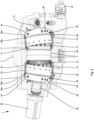
- Figs. 3-5 show an interior side of the hydraulic transformer 1.
- the hydraulic transformer 1 has a hollow main shaft 6 which is supported by the housing 2 through a pair of angular contact roller bearings 7.
- the main shaft 6 is rotatable with respect to the housing 2 about a first axis of rotation 8.
- the bearings 7 are located at a central portion of the housing 2 as seen in longitudinal direction of the first axis of rotation 8.
- the bearings 7 have fixed positions with respect to the housing 2 in longitudinal direction of the first axis of rotation 8 by means of a collar 9 of the housing 2 and a sleeve 10 between which circumferential outer edges of the bearings 7 are sandwiched.
- the main shaft 6 is provided with a first flange 11 and a second flange 12, which extend perpendicularly to the first axis of rotation 8 at either side of the bearings 7. Circumferential inner edges of the bearings 7 are sandwiched between the first and second flanges 11, 12.
- the second flange 12 is mounted as a separate element onto the main shaft 6 after placing the bearings 7 next to the first flange 11.
- a key 13 locks the second flange 12 with respect to the main shaft 6 in rotational direction about the first axis of rotation 8.
- the second flange 12 has a toothed circumference which is used for rotational speed detection, see Fig. 3 .
- a plurality of pistons 14 are fixed at equiangular distance about the first axis of rotation 8, in this case fifteen pistons 14.
- the pistons 14 project from the respective first and second flanges 11, 12 away from each other.
- the pistons 14 have centre lines which extend parallel to the first axis of rotation 8. In this case they are fixed to the respective first and second flanges 11, 12 by screws, but alternative fixing means are conceivable.
- Each of the pistons 14 cooperates with a separate sleeve 15 to form a compression chamber of variable volume.
- the hydraulic transformer 1 has 30 compression chambers.
- Each of the sleeves 15 comprises a sleeve bottom 16 including a central through-hole 17 and a circular-cylindrical sleeve jacket 18, see Fig. 5 .
- the sleeve jacket 18 extends from the sleeve bottom 16.
- Each piston 14 is sealed directly to the inner wall of the cooperating sleeve jacket 18 through a piston head of the piston 14 which has a spherical outer side.
- the sleeve bottoms 16 are supported by a bearing surface of a first barrel member 19 and a bearing surface of a second barrel member 20.
- the sleeves 15 are slidable on the bearing surfaces of the first and second barrel members 19, 20, which is known as the floating cup principle.
- the first and second barrel members 19, 20 are fitted around the main shaft 6 by means of respective ball hinges 21 and are coupled to the main shaft 6 by means of keys 22, see Fig. 5 . Consequently, the first and second barrel members 19, 20 rotate together with the main shaft 6 under operating conditions.
- the first and second barrel members 19, 20 are the same.
- Fig. 6 shows the first barrel member 19 in more detail.
- the first barrel member 19 has a front side 23 and a back side 24.
- the back side 24 is opposite to the front side 23 and the bearing surface.
- the front side 23 is directed to the first flange 11 and the back side 24 is directed away from the first flange 11.
- Each compression chamber communicates via the through-hole 17 in the sleeve bottom 16 and a barrel member passage with a barrel port 27 at the back side 24 of the first barrel member 19.
- each of the barrel ports 27 comprises a pair of openings at the back side 24 of the first barrel member 19.
- the hydraulic transformer 1 has a first face plate 28 which is sandwiched between the housing 2 and the first barrel member 19 as well as a second face plate 29 which is sandwiched between the housing 2 and the second barrel member 20.
- the first and second face plates 28, 29 are functionally the same, but mirrored with respect to a plane that extends perpendicularly to the first axis of rotation 8 and between the first and second face plates 28, 29.
- the first face plate 28 comprises a front part 28a and a back part 28b which have fixed positions with respect to each other.
- the first part 28a and the back part 28b may be made of different materials, but alternatively the first face plate 28 may be a single part.
- the second face plate 29 has a front part 29a and a back part 29b.
- the first and second face plates 28, 29 will be described as if they are single parts, respectively.
- Fig. 7 shows a front side 30 of the second face plate 29 which is directed to the back side 24 of the second barrel member 20.
- Fig. 8 shows a back side 31 of the second face plate 29 which is directed to a wall of the housing 2.
- the wall of the housing 2 supports the second face plate 29 which in turn supports the second barrel member 20.
- an opposite wall of the housing 2 supports the first face plate 28 which in turn supports the first barrel member 19.
- the housing 2 is adapted such that the first and second face plates 28, 29 have an inclined orientation such that the first barrel member 19 and the second barrel member 20 are rotatable about a second axis of rotation 32a and a third axis of rotation 32b, respectively, which second axis of rotation 32a and third axis of rotation 32b are angled by acute angles with respect to the first axis of rotation 8.
- the first and second barrel members 19, 20 pivot about the respective ball hinges 21 during rotation with the main shaft 6.
- the sleeves 15 rotate about the respective second and third axes of rotation 32a, 32b. Consequently, upon rotating the main shaft 6 the volumes of the compression chambers change.
- the angle between the first axis of rotation 8 and the second axes of rotation 32a and between the first axis of rotation 8 and the third axis of rotation 32b is approximately eight degrees in practice, but may be smaller or larger.
- the first and second barrel members 19, 20 are pressed against the first and second face plates 28, 29, respectively by means of springs 33 which are mounted in holes in the main shaft 6 and which press respective cheeks 34 against the first and second barrel members 19, 20, see Fig. 5 .
- each sleeve 15 makes a combined translating and swivelling motion around the cooperating piston 14. Therefore, the outer side of each piston head is spherical.
- the spherical shape creates a sealing line between the piston head and the sleeve jacket 18 which extends perpendicularly to a centre line of the cooperating sleeve 15.
- the diameter of each piston 14 near the corresponding first or second flange 11, 12 is smaller than at the piston head in order to allow the relative motion of the cooperating sleeves 15 about the pistons 14.
- each of the pistons 14 moves inside the cooperating sleeve 15 between a bottom dead centre and a top dead centre.
- the upper pistons 14 at the first and second barrel members 19, 20 are in top dead centre and the lower pistons 14 at the first and second barrel members 19, 20 are in bottom dead centre.
- the second face plate 29 is provided with a high-pressure passage 35, a low-pressure passage 36 and an operating pressure passage 37.
- the high-pressure passage 35 comprises eight through-holes and forms a high-pressure port at its front side 30 and a high-pressure port at its back side 31.
- the respective high-pressure ports are partly circular and extend within an angle of about 160° about the third axis of rotation 32b, but a different arc length is conceivable.
- the low-pressure passage 36 comprises four through-holes and forms a low-pressure port at its front side 30 and a low-pressure port at its back side 31.
- the low-pressure port is partly circular and is shorter than the length of the high-pressure port, as measured in rotational direction about the third axis of rotation 32b, both at the front side 30 and the back side 31.
- the operating pressure passage 37 comprises three through-holes and forms an operating pressure port at its front side 30 and an operating pressure port at its back side 31.
- the operating pressure port is partly circular and is shorter than the length of the low-pressure port, as measured in rotational direction about the third axis of rotation 32b, both at the front side 30 and the back side 31.
- the barrel ports 27 of the second barrel member 20 travel along the high-pressure port, the low-pressure port and the operating pressure port at the front side 30 of the second face plate 29.
- the barrel ports 27 of the first barrel member 19 travel along the high-pressure port, the low-pressure port and the operating pressure port at the front side 30 of the first face plate 28.
- the high-pressure passages 35 of the first and second face plates 28, 29 communicate with the high-pressure connection 3 of the housing 2
- the low-pressure passages 36 of the first and second face plates 28, 29 communicate with the low-pressure connection 4 of the housing 2
- the operating pressure passages 37 of the first and second face plates 28, 29 communicate with the two operating pressure connections 5 of the housing 2.
- the first and second face plates 28, 29 are rotatable with respect to the housing 2 through a predetermined angle ⁇ about the second and third axes of rotation 32a, 32b, respectively, for example 70°.
- the second face plate 29 is rotatable by a servo-actuator 38, whereas the first face plate 28 is synchronously rotatable with the second face plate 29 by means of a hollow auxiliary shaft 39 which couples the first and second face plates 28, 29 to each other through pins 40, see Figs. 3-5 .
- Fig. 9 shows an inner wall of the housing 2 which supports the back side 31 of the second face plate 29.
- the inner wall is provided with a partly circular high-pressure port 41 which communicates with the high-pressure connection 3 of the housing 2.
- Fig. 9 illustrates two extreme rotational positions of the second face plate 29 with respect to the housing 2 about the third axis of rotation 32b by means of a projection A of the high-pressure port of the high-pressure passages 35 at the back side 31 of the second face plate 29, a projection T of the low-pressure port of the low-pressure passages 36 at the back side 31 of the second face plate 29 and a projection B of the operating pressure port of the operating pressure passages 37 at the back side 31 of the second face plate 29 by respective broken lines.
- the high-pressure port 41 of the housing 2 communicates with the high-pressure port at the back side 31 of the second face plate 29. It can be seen that the arc length of the high-pressure port 41 of the housing 2 is shorter than the arc length of the high-pressure port at the back side 31 of the second face plate 29. This means that a part of the high-pressure port at the back side 31 of the second face plate 29 is always closed by the wall of the housing 2.
- the second face plate 29 can be provided with channels 42 between non-adjacent high-pressure passages 35, see Fig. 7 .
- the channels 42 are drilled from a circumferential outer side of the second face plate 29, whereas inserts 43 seal the respective channels 42.
- the first face plate 28 and the wall of the housing 2 that supports the first face plate 28 are similar to the second face plate 29 and the wall of the housing 2 that supports the second face plate 29.
- the housing 2 is provided with a high-pressure channel 44 through which the high-pressure ports at the back sides 31 of the respective first and second face plates 28, 29 communicate with the high-pressure connection 3 of the housing 2.
- Fig. 10 illustrates by broken lines and arrows that hydraulic fluid can flow in opposite directions through the high-pressure channel 44.
- the low-pressure channels 36 are formed by through-holes between the front side 30 and the back side 31 of the second face plate 29 and radial channels 45 which are drilled from the circumferential outer side of the second face plate 29 to the respective through-holes.
- the through-holes are closed at the back side 31 of the second face plate 29 by the wall of the housing 2 as shown in Fig. 9 by projection T.
- the low-pressure channels 36 form 90 degree bends in the first and second face plates 28, 29.
- the low-pressure channels 36 communicate with the low-pressure connection 4 through a low-pressure channel 46, which is formed by an internal space of the housing 2.
- Fig. 11 shows flow patterns of hydraulic fluid through the low-pressure channel 46 by broken lines and arrows, indicating that the hydraulic fluid can flow in opposite directions.
- the operating pressure channels 37 are formed by through-holes between the front side 30 and the back side 31 of the second face plate 29 and radial holes 48 which are drilled from the circumferential outer side of the second face plate 29 to a central hole 49 in the second face plate 29 whereas passing the respective through-holes.
- the central hole 49 is a through-hole.
- Inserts 50 seal the respective radial holes 48 at the circumference of the second face plate 29.
- the through-holes of the operating pressure channels 37 are closed at the back side 31 of the second face plate 29 by the wall of the housing 2 as shown in Fig. 9 by projection B. This means that the operating pressure channels 37 form 90 degree bends in the first and second face plates 28, 29.
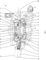
- the operating pressure channels 37 communicate with the operating pressure connections 5 through an operating pressure channel 51, which is formed by the central holes 49 of the first and second face plates 28, 29, central holes in the first and second barrel members 19, 20 and the internal space of the main shaft 6, see Fig. 12 .
- the operating pressure channel 51 is sealed with respect to the low-pressure channel 46, i.e. the internal space of the housing 2, by means of inner sleeves 52 and cooperating outer sleeves 53, see Fig. 5 .
- the outer sleeves 53 are mounted to the first and second barrel members 19, 20, respectively. They may be slidable with respect to the first and second barrel members 19, 20 along the second and third axes of rotation 32a, 32b, respectively.
- Each of the inner sleeves 52 is fixed to the main shaft 6 and has a spherical outer surface portion which contacts a circular cylindrical inner wall of the cooperating outer sleeve 53.
- the spherical outer surface portions may have centre points which coincide with centre points of the respective ball hinges 21.
- Fig. 12 shows flow patterns of hydraulic fluid through the operating pressure passages 37 and the operating pressure channel 51 by broken lines and arrows. Although not shown in Fig. 12 , the hydraulic fluid can also flow in opposite directions.
- the high-pressure port at the front side 30 of the second face plate 29 and the high-pressure port at the back side 31 of the second face plate 29 are aligned and have substantially the same shape and dimensions.
- the low-pressure port at the front side 30 of the second face plate 29 and the low-pressure port at the back side 31 of the second face plate 29 are aligned and have substantially the same shape and dimensions.
- the operating pressure port at the front side 30 of the second face plate 29 and the operating pressure port at the back side 31 of the second face plate 29 are aligned and have substantially the same shape and dimensions.
- Fig. 7 shows that the second face plate 29 is provided with series of small through-holes 54 at sealing lands between the high-pressure port and the low-pressure port, between the low-pressure port and the operating pressure port and between the high-pressure port and the operating pressure port, as seen in angular direction about the third axis of rotation 32b.
- the flow-through area of each through-hole 54 at the front side 30 of the second face plate 29 is smaller than 5% of the flow-through area of the first passage 35 and also smaller than the flow-through area of each of the barrel ports 27 of the second barrel member 20 which travel along the through-holes 54.
- Fig. 8 shows that at the back side 31 of the second face plate 29 the through-holes 54 form pockets 55 which have a larger cross-sectional area than the through-holes 54 at the front side 30 of the second face plate 29.
- the barrel ports 27 of the second barrel member 20 travel along the through-holes 54, hence generating pressure fields at the front side 30 of the second face plate 29 between the high-pressure port and the low-pressure port, between the low-pressure port and the operating pressure port and between the high-pressure port and the operating pressure port.
- Due to the presence of the through-holes 54 and the pockets 55 counteracting pressure fields are generated at the back side 31 of the second face plate 29. This leads to minimized friction between the second face plate 29 and the housing 2, which facilitates adjustment of the rotational position of the second face plate 29 with respect to the housing 2.
- the first face plate 28 is also provided with the through-holes 54 and the pockets 55.
- the second face plate 29 is rotatable by a servo-actuator 38 which needs to overcome torque load of the first and second face plates 28, 29.
- the servo-actuator 38 is coupled to an electric servomotor 56 which controls a control shaft 57 including ports which communicate with the low-pressure channel 46 and the high-pressure channel 44, respectively.
- the hydraulic servo-actuator 38 has a rotor and a stator, each having three ribs which form six displacement chambers. The pressures in these chambers are controlled by means of the rotational position of the control shaft 57.
- the actual rotational position of the second face plate 29 with respect to the housing 2 is determined by a position sensor 58.
- the angle of rotation of the first and second face plates 28, 29 is defined by respective arcuate grooves 59 in their back sides 31, see Figs. 5 and 8 , in which grooves 59 pins 60 are received, see Fig. 4 .
- the pins 60 may be bolts which are screwed in the housing 2.
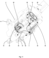
- Fig. 13 illustrates a hydraulic circuit in and around the hydraulic transformer 1.
- the operating pressure connections 5 are coupled to a hydraulic cylinder which can be extended and retracted through control valves 61, which are also indicated in Figs. 1-4 and 10-11 .
- the high-pressure connection 3 communicates with a high-pressure line HP and the low-pressure connection 4 communicates with a low-pressure line LP.
- the hydraulic transformer 1 also has two check valves 62 for avoiding cavitation, which check valves 62 are also indicated in Figs. 1 and 11 .
- Figs. 11 and 13 show that the low-pressure channel 46 is fluidly connected with the check valves 62 and the control valves 61.
- Fig. 13 shows that the operating pressure channel 51 is fluidly connected with the control valves 61.
- the control valves 61 can be operated such that hydraulic fluid flows from the operating pressure channel 51 to a lower side of the hydraulic cylinder and from an upper side of the hydraulic cylinder to the low-pressure channel 46 for extending the hydraulic cylinder.
- the control valves 61 can be operated such that hydraulic fluid flows from the lower side of the hydraulic cylinder to the operating pressure channel 51 and from the low-pressure channel 46 to the upper side of the hydraulic cylinder for retracting the hydraulic cylinder.
- the load may force the hydraulic fluid to flow through the operating pressure channel 51, which results in transporting compressed hydraulic fluid via the high-pressure channel 44 and the high-pressure connection 3 to the high-pressure line HP.
- the energy for retracting the cylinder by the external load is recuperated and converted to hydraulic pressure in the high-pressure line HP.
- the high-pressure line HP and also the low-pressure line LP may be provided with pressure accumulators.
Landscapes
- Engineering & Computer Science (AREA)
- Mechanical Engineering (AREA)
- General Engineering & Computer Science (AREA)
- Chemical & Material Sciences (AREA)
- Combustion & Propulsion (AREA)
- Reciprocating Pumps (AREA)
- Hydraulic Motors (AREA)
Priority Applications (3)
| Application Number | Priority Date | Filing Date | Title |
|---|---|---|---|
| EP23159986.1A EP4424985B1 (de) | 2023-03-03 | 2023-03-03 | Hydraulischer transformator |
| PCT/EP2024/055045 WO2024184141A1 (en) | 2023-03-03 | 2024-02-28 | A hydraulic transformer |
| CN202480015831.8A CN120936799A (zh) | 2023-03-03 | 2024-02-28 | 一种液压变换器 |
Applications Claiming Priority (1)
| Application Number | Priority Date | Filing Date | Title |
|---|---|---|---|
| EP23159986.1A EP4424985B1 (de) | 2023-03-03 | 2023-03-03 | Hydraulischer transformator |
Publications (3)
| Publication Number | Publication Date |
|---|---|
| EP4424985A1 true EP4424985A1 (de) | 2024-09-04 |
| EP4424985B1 EP4424985B1 (de) | 2025-08-20 |
| EP4424985C0 EP4424985C0 (de) | 2025-08-20 |
Family
ID=85461647
Family Applications (1)
| Application Number | Title | Priority Date | Filing Date |
|---|---|---|---|
| EP23159986.1A Active EP4424985B1 (de) | 2023-03-03 | 2023-03-03 | Hydraulischer transformator |
Country Status (3)
| Country | Link |
|---|---|
| EP (1) | EP4424985B1 (de) |
| CN (1) | CN120936799A (de) |
| WO (1) | WO2024184141A1 (de) |
Citations (6)
| Publication number | Priority date | Publication date | Assignee | Title |
|---|---|---|---|---|
| EP0882181B1 (de) * | 1996-02-23 | 2002-05-29 | Innas Free Piston B.V. | Drucktransformationseinrichtung |
| US20020078686A1 (en) * | 2000-12-22 | 2002-06-27 | Endsley John C. | Hydraulic pressure transformer |
| NL1019736C1 (nl) | 2002-01-12 | 2003-07-15 | Innas Bv | Hydraulische inrichting. |
| US20070251378A1 (en) * | 2006-04-27 | 2007-11-01 | Caterpillar Inc. | Dual flow axial piston pump |
| US20080159879A1 (en) * | 2004-03-03 | 2008-07-03 | Bosch Rexroth Ag | Axial Piston Machine |
| CN102788010B (zh) * | 2012-08-10 | 2015-11-18 | 中国船舶重工集团公司第七一九研究所 | 一种摆动油缸控制的斜盘柱塞式液压变压器 |
-
2023
- 2023-03-03 EP EP23159986.1A patent/EP4424985B1/de active Active
-
2024
- 2024-02-28 CN CN202480015831.8A patent/CN120936799A/zh active Pending
- 2024-02-28 WO PCT/EP2024/055045 patent/WO2024184141A1/en not_active Ceased
Patent Citations (6)
| Publication number | Priority date | Publication date | Assignee | Title |
|---|---|---|---|---|
| EP0882181B1 (de) * | 1996-02-23 | 2002-05-29 | Innas Free Piston B.V. | Drucktransformationseinrichtung |
| US20020078686A1 (en) * | 2000-12-22 | 2002-06-27 | Endsley John C. | Hydraulic pressure transformer |
| NL1019736C1 (nl) | 2002-01-12 | 2003-07-15 | Innas Bv | Hydraulische inrichting. |
| US20080159879A1 (en) * | 2004-03-03 | 2008-07-03 | Bosch Rexroth Ag | Axial Piston Machine |
| US20070251378A1 (en) * | 2006-04-27 | 2007-11-01 | Caterpillar Inc. | Dual flow axial piston pump |
| CN102788010B (zh) * | 2012-08-10 | 2015-11-18 | 中国船舶重工集团公司第七一九研究所 | 一种摆动油缸控制的斜盘柱塞式液压变压器 |
Also Published As
| Publication number | Publication date |
|---|---|
| EP4424985B1 (de) | 2025-08-20 |
| WO2024184141A1 (en) | 2024-09-12 |
| CN120936799A (zh) | 2025-11-11 |
| EP4424985C0 (de) | 2025-08-20 |
Similar Documents
| Publication | Publication Date | Title |
|---|---|---|
| US7967574B2 (en) | Variable pump or hydraulic motor | |
| KR950013019B1 (ko) | 스크로울형 압축기 | |
| US3796232A (en) | Rotary direction flow control valve | |
| EP3246565B1 (de) | Hydraulikvorrichtung | |
| EP4424985B1 (de) | Hydraulischer transformator | |
| EP3246567B1 (de) | Hydraulikvorrichtung | |
| US11767830B2 (en) | Hydraulic system | |
| JP3059230B2 (ja) | ラジアル・ピストンポンプ | |
| USRE26519E (en) | Variable displacement pump | |
| US6460333B2 (en) | Hydraulic pressure transformer | |
| EP4083424B1 (de) | Hydraulikvorrichtung | |
| EP1882081B1 (de) | Ausgleichsplatten-shuttleventil | |
| US3188972A (en) | Axial piston hydraulic unit | |
| US6751955B1 (en) | Stirling engine with swashplate actuator | |
| US20080257432A1 (en) | Valve including a rotary spool and check valves | |
| EP3333447A1 (de) | Hydraulischer rotationsstossdämpfer | |
| US20070240563A1 (en) | DOUBLE-ACTING RADIAL PlSTON HYDRAULIC APPARATUS | |
| US20180058432A1 (en) | Hydrostatic Axial Piston Machine | |
| NO171872B (no) | Oscillerende vinge-anordning, som aktuator eller pumpe | |
| US3255705A (en) | Rotary machine having vanes | |
| EP4459123A1 (de) | Hydraulische vorrichtung | |
| EP4269790A1 (de) | Hydraulikvorrichtung | |
| JP2763114B2 (ja) | 回転ピストンポンプ並びにモータ | |
| CN120926052A (zh) | 具有包括两个子室的单独的预压缩结构组件的轴向活塞机 | |
| EP0592416A1 (de) | Ventilvorrichtung |
Legal Events
| Date | Code | Title | Description |
|---|---|---|---|
| PUAI | Public reference made under article 153(3) epc to a published international application that has entered the european phase |
Free format text: ORIGINAL CODE: 0009012 |
|
| STAA | Information on the status of an ep patent application or granted ep patent |
Free format text: STATUS: THE APPLICATION HAS BEEN PUBLISHED |
|
| AK | Designated contracting states |
Kind code of ref document: A1 Designated state(s): AL AT BE BG CH CY CZ DE DK EE ES FI FR GB GR HR HU IE IS IT LI LT LU LV MC ME MK MT NL NO PL PT RO RS SE SI SK SM TR |
|
| STAA | Information on the status of an ep patent application or granted ep patent |
Free format text: STATUS: REQUEST FOR EXAMINATION WAS MADE |
|
| GRAP | Despatch of communication of intention to grant a patent |
Free format text: ORIGINAL CODE: EPIDOSNIGR1 |
|
| STAA | Information on the status of an ep patent application or granted ep patent |
Free format text: STATUS: GRANT OF PATENT IS INTENDED |
|
| 17P | Request for examination filed |
Effective date: 20250224 |
|
| RIC1 | Information provided on ipc code assigned before grant |
Ipc: F01B 3/00 20060101ALI20250312BHEP Ipc: F04B 1/2035 20200101ALI20250312BHEP Ipc: F03C 1/32 20060101ALI20250312BHEP Ipc: F04B 1/306 20200101ALI20250312BHEP Ipc: F04B 1/303 20200101ALI20250312BHEP Ipc: F04B 1/24 20060101ALI20250312BHEP Ipc: F04B 1/2092 20200101ALI20250312BHEP Ipc: F04B 1/2021 20200101ALI20250312BHEP Ipc: F04B 1/20 20200101ALI20250312BHEP Ipc: F03C 1/40 20060101ALI20250312BHEP Ipc: F03C 1/06 20060101AFI20250312BHEP |
|
| INTG | Intention to grant announced |
Effective date: 20250325 |
|
| GRAS | Grant fee paid |
Free format text: ORIGINAL CODE: EPIDOSNIGR3 |
|
| GRAA | (expected) grant |
Free format text: ORIGINAL CODE: 0009210 |
|
| STAA | Information on the status of an ep patent application or granted ep patent |
Free format text: STATUS: THE PATENT HAS BEEN GRANTED |
|
| AK | Designated contracting states |
Kind code of ref document: B1 Designated state(s): AL AT BE BG CH CY CZ DE DK EE ES FI FR GB GR HR HU IE IS IT LI LT LU LV MC ME MK MT NL NO PL PT RO RS SE SI SK SM TR |
|
| REG | Reference to a national code |
Ref country code: GB Ref legal event code: FG4D |
|
| REG | Reference to a national code |
Ref country code: CH Ref legal event code: EP |
|
| REG | Reference to a national code |
Ref country code: IE Ref legal event code: FG4D |
|
| REG | Reference to a national code |
Ref country code: DE Ref legal event code: R096 Ref document number: 602023005783 Country of ref document: DE |
|
| U01 | Request for unitary effect filed |
Effective date: 20250903 |
|
| U07 | Unitary effect registered |
Designated state(s): AT BE BG DE DK EE FI FR IT LT LU LV MT NL PT RO SE SI Effective date: 20250910 |
|
| PG25 | Lapsed in a contracting state [announced via postgrant information from national office to epo] |
Ref country code: IS Free format text: LAPSE BECAUSE OF FAILURE TO SUBMIT A TRANSLATION OF THE DESCRIPTION OR TO PAY THE FEE WITHIN THE PRESCRIBED TIME-LIMIT Effective date: 20251220 |
|
| PG25 | Lapsed in a contracting state [announced via postgrant information from national office to epo] |
Ref country code: HR Free format text: LAPSE BECAUSE OF FAILURE TO SUBMIT A TRANSLATION OF THE DESCRIPTION OR TO PAY THE FEE WITHIN THE PRESCRIBED TIME-LIMIT Effective date: 20250820 |
|
| PG25 | Lapsed in a contracting state [announced via postgrant information from national office to epo] |
Ref country code: GR Free format text: LAPSE BECAUSE OF FAILURE TO SUBMIT A TRANSLATION OF THE DESCRIPTION OR TO PAY THE FEE WITHIN THE PRESCRIBED TIME-LIMIT Effective date: 20251121 |
|
| PG25 | Lapsed in a contracting state [announced via postgrant information from national office to epo] |
Ref country code: PL Free format text: LAPSE BECAUSE OF FAILURE TO SUBMIT A TRANSLATION OF THE DESCRIPTION OR TO PAY THE FEE WITHIN THE PRESCRIBED TIME-LIMIT Effective date: 20250820 |
|
| PG25 | Lapsed in a contracting state [announced via postgrant information from national office to epo] |
Ref country code: RS Free format text: LAPSE BECAUSE OF FAILURE TO SUBMIT A TRANSLATION OF THE DESCRIPTION OR TO PAY THE FEE WITHIN THE PRESCRIBED TIME-LIMIT Effective date: 20251120 |
|
| PG25 | Lapsed in a contracting state [announced via postgrant information from national office to epo] |
Ref country code: ES Free format text: LAPSE BECAUSE OF FAILURE TO SUBMIT A TRANSLATION OF THE DESCRIPTION OR TO PAY THE FEE WITHIN THE PRESCRIBED TIME-LIMIT Effective date: 20250820 |