EP4424918A1 - Work machine - Google Patents
Work machine Download PDFInfo
- Publication number
- EP4424918A1 EP4424918A1 EP24158787.2A EP24158787A EP4424918A1 EP 4424918 A1 EP4424918 A1 EP 4424918A1 EP 24158787 A EP24158787 A EP 24158787A EP 4424918 A1 EP4424918 A1 EP 4424918A1
- Authority
- EP
- European Patent Office
- Prior art keywords
- pipe
- battery
- battery unit
- battery units
- work machine
- Prior art date
- Legal status (The legal status is an assumption and is not a legal conclusion. Google has not performed a legal analysis and makes no representation as to the accuracy of the status listed.)
- Pending
Links
Images


Classifications
-
- E—FIXED CONSTRUCTIONS
- E02—HYDRAULIC ENGINEERING; FOUNDATIONS; SOIL SHIFTING
- E02F—DREDGING; SOIL-SHIFTING
- E02F9/00—Component parts of dredgers or soil-shifting machines, not restricted to one of the kinds covered by groups E02F3/00 - E02F7/00
- E02F9/20—Drives; Control devices
- E02F9/2058—Electric or electro-mechanical or mechanical control devices of vehicle sub-units
- E02F9/2091—Control of energy storage means for electrical energy, e.g. battery or capacitors
-
- E—FIXED CONSTRUCTIONS
- E02—HYDRAULIC ENGINEERING; FOUNDATIONS; SOIL SHIFTING
- E02F—DREDGING; SOIL-SHIFTING
- E02F9/00—Component parts of dredgers or soil-shifting machines, not restricted to one of the kinds covered by groups E02F3/00 - E02F7/00
- E02F9/08—Superstructures; Supports for superstructures
- E02F9/0858—Arrangement of component parts installed on superstructures not otherwise provided for, e.g. electric components, fenders, air-conditioning units
- E02F9/0866—Engine compartment, e.g. heat exchangers, exhaust filters, cooling devices, silencers, mufflers, position of hydraulic pumps in the engine compartment
-
- E—FIXED CONSTRUCTIONS
- E02—HYDRAULIC ENGINEERING; FOUNDATIONS; SOIL SHIFTING
- E02F—DREDGING; SOIL-SHIFTING
- E02F9/00—Component parts of dredgers or soil-shifting machines, not restricted to one of the kinds covered by groups E02F3/00 - E02F7/00
- E02F9/08—Superstructures; Supports for superstructures
- E02F9/0858—Arrangement of component parts installed on superstructures not otherwise provided for, e.g. electric components, fenders, air-conditioning units
-
- B—PERFORMING OPERATIONS; TRANSPORTING
- B60—VEHICLES IN GENERAL
- B60H—ARRANGEMENTS OF HEATING, COOLING, VENTILATING OR OTHER AIR-TREATING DEVICES SPECIALLY ADAPTED FOR PASSENGER OR GOODS SPACES OF VEHICLES
- B60H1/00—Heating, cooling or ventilating devices
- B60H1/00271—HVAC devices specially adapted for particular vehicle parts or components and being connected to the vehicle HVAC unit
- B60H1/00278—HVAC devices specially adapted for particular vehicle parts or components and being connected to the vehicle HVAC unit for the battery
-
- B—PERFORMING OPERATIONS; TRANSPORTING
- B60—VEHICLES IN GENERAL
- B60K—ARRANGEMENT OR MOUNTING OF PROPULSION UNITS OR OF TRANSMISSIONS IN VEHICLES; ARRANGEMENT OR MOUNTING OF PLURAL DIVERSE PRIME-MOVERS IN VEHICLES; AUXILIARY DRIVES FOR VEHICLES; INSTRUMENTATION OR DASHBOARDS FOR VEHICLES; ARRANGEMENTS IN CONNECTION WITH COOLING, AIR INTAKE, GAS EXHAUST OR FUEL SUPPLY OF PROPULSION UNITS IN VEHICLES
- B60K1/00—Arrangement or mounting of electrical propulsion units
- B60K1/04—Arrangement or mounting of electrical propulsion units of the electric storage means for propulsion
-
- B—PERFORMING OPERATIONS; TRANSPORTING
- B60—VEHICLES IN GENERAL
- B60L—PROPULSION OF ELECTRICALLY-PROPELLED VEHICLES; SUPPLYING ELECTRIC POWER FOR AUXILIARY EQUIPMENT OF ELECTRICALLY-PROPELLED VEHICLES; ELECTRODYNAMIC BRAKE SYSTEMS FOR VEHICLES IN GENERAL; MAGNETIC SUSPENSION OR LEVITATION FOR VEHICLES; MONITORING OPERATING VARIABLES OF ELECTRICALLY-PROPELLED VEHICLES; ELECTRIC SAFETY DEVICES FOR ELECTRICALLY-PROPELLED VEHICLES
- B60L1/00—Supplying electric power to auxiliary equipment of vehicles
- B60L1/003—Supplying electric power to auxiliary equipment of vehicles to auxiliary motors, e.g. for pumps, compressors
-
- B—PERFORMING OPERATIONS; TRANSPORTING
- B60—VEHICLES IN GENERAL
- B60L—PROPULSION OF ELECTRICALLY-PROPELLED VEHICLES; SUPPLYING ELECTRIC POWER FOR AUXILIARY EQUIPMENT OF ELECTRICALLY-PROPELLED VEHICLES; ELECTRODYNAMIC BRAKE SYSTEMS FOR VEHICLES IN GENERAL; MAGNETIC SUSPENSION OR LEVITATION FOR VEHICLES; MONITORING OPERATING VARIABLES OF ELECTRICALLY-PROPELLED VEHICLES; ELECTRIC SAFETY DEVICES FOR ELECTRICALLY-PROPELLED VEHICLES
- B60L50/00—Electric propulsion with power supplied within the vehicle
- B60L50/50—Electric propulsion with power supplied within the vehicle using propulsion power supplied by batteries or fuel cells
- B60L50/60—Electric propulsion with power supplied within the vehicle using propulsion power supplied by batteries or fuel cells using power supplied by batteries
- B60L50/64—Constructional details of batteries specially adapted for electric vehicles
-
- B—PERFORMING OPERATIONS; TRANSPORTING
- B60—VEHICLES IN GENERAL
- B60L—PROPULSION OF ELECTRICALLY-PROPELLED VEHICLES; SUPPLYING ELECTRIC POWER FOR AUXILIARY EQUIPMENT OF ELECTRICALLY-PROPELLED VEHICLES; ELECTRODYNAMIC BRAKE SYSTEMS FOR VEHICLES IN GENERAL; MAGNETIC SUSPENSION OR LEVITATION FOR VEHICLES; MONITORING OPERATING VARIABLES OF ELECTRICALLY-PROPELLED VEHICLES; ELECTRIC SAFETY DEVICES FOR ELECTRICALLY-PROPELLED VEHICLES
- B60L50/00—Electric propulsion with power supplied within the vehicle
- B60L50/50—Electric propulsion with power supplied within the vehicle using propulsion power supplied by batteries or fuel cells
- B60L50/60—Electric propulsion with power supplied within the vehicle using propulsion power supplied by batteries or fuel cells using power supplied by batteries
- B60L50/66—Arrangements of batteries
-
- B—PERFORMING OPERATIONS; TRANSPORTING
- B60—VEHICLES IN GENERAL
- B60L—PROPULSION OF ELECTRICALLY-PROPELLED VEHICLES; SUPPLYING ELECTRIC POWER FOR AUXILIARY EQUIPMENT OF ELECTRICALLY-PROPELLED VEHICLES; ELECTRODYNAMIC BRAKE SYSTEMS FOR VEHICLES IN GENERAL; MAGNETIC SUSPENSION OR LEVITATION FOR VEHICLES; MONITORING OPERATING VARIABLES OF ELECTRICALLY-PROPELLED VEHICLES; ELECTRIC SAFETY DEVICES FOR ELECTRICALLY-PROPELLED VEHICLES
- B60L58/00—Methods or circuit arrangements for monitoring or controlling batteries or fuel cells, specially adapted for electric vehicles
- B60L58/10—Methods or circuit arrangements for monitoring or controlling batteries or fuel cells, specially adapted for electric vehicles for monitoring or controlling batteries
- B60L58/24—Methods or circuit arrangements for monitoring or controlling batteries or fuel cells, specially adapted for electric vehicles for monitoring or controlling batteries for controlling the temperature of batteries
- B60L58/26—Methods or circuit arrangements for monitoring or controlling batteries or fuel cells, specially adapted for electric vehicles for monitoring or controlling batteries for controlling the temperature of batteries by cooling
-
- B—PERFORMING OPERATIONS; TRANSPORTING
- B60—VEHICLES IN GENERAL
- B60L—PROPULSION OF ELECTRICALLY-PROPELLED VEHICLES; SUPPLYING ELECTRIC POWER FOR AUXILIARY EQUIPMENT OF ELECTRICALLY-PROPELLED VEHICLES; ELECTRODYNAMIC BRAKE SYSTEMS FOR VEHICLES IN GENERAL; MAGNETIC SUSPENSION OR LEVITATION FOR VEHICLES; MONITORING OPERATING VARIABLES OF ELECTRICALLY-PROPELLED VEHICLES; ELECTRIC SAFETY DEVICES FOR ELECTRICALLY-PROPELLED VEHICLES
- B60L58/00—Methods or circuit arrangements for monitoring or controlling batteries or fuel cells, specially adapted for electric vehicles
- B60L58/10—Methods or circuit arrangements for monitoring or controlling batteries or fuel cells, specially adapted for electric vehicles for monitoring or controlling batteries
- B60L58/24—Methods or circuit arrangements for monitoring or controlling batteries or fuel cells, specially adapted for electric vehicles for monitoring or controlling batteries for controlling the temperature of batteries
- B60L58/27—Methods or circuit arrangements for monitoring or controlling batteries or fuel cells, specially adapted for electric vehicles for monitoring or controlling batteries for controlling the temperature of batteries by heating
-
- E—FIXED CONSTRUCTIONS
- E02—HYDRAULIC ENGINEERING; FOUNDATIONS; SOIL SHIFTING
- E02F—DREDGING; SOIL-SHIFTING
- E02F3/00—Dredgers; Soil-shifting machines
- E02F3/04—Dredgers; Soil-shifting machines mechanically-driven
- E02F3/28—Dredgers; Soil-shifting machines mechanically-driven with digging tools mounted on a dipper- or bucket-arm, i.e. there is either one arm or a pair of arms, e.g. dippers, buckets
- E02F3/30—Dredgers; Soil-shifting machines mechanically-driven with digging tools mounted on a dipper- or bucket-arm, i.e. there is either one arm or a pair of arms, e.g. dippers, buckets with a dipper-arm pivoted on a cantilever beam, i.e. boom
- E02F3/32—Dredgers; Soil-shifting machines mechanically-driven with digging tools mounted on a dipper- or bucket-arm, i.e. there is either one arm or a pair of arms, e.g. dippers, buckets with a dipper-arm pivoted on a cantilever beam, i.e. boom working downwardly and towards the machine, e.g. with backhoes
- E02F3/325—Backhoes of the miniature type
-
- E—FIXED CONSTRUCTIONS
- E02—HYDRAULIC ENGINEERING; FOUNDATIONS; SOIL SHIFTING
- E02F—DREDGING; SOIL-SHIFTING
- E02F9/00—Component parts of dredgers or soil-shifting machines, not restricted to one of the kinds covered by groups E02F3/00 - E02F7/00
- E02F9/20—Drives; Control devices
- E02F9/2058—Electric or electro-mechanical or mechanical control devices of vehicle sub-units
- E02F9/2062—Control of propulsion units
- E02F9/207—Control of propulsion units of the type electric propulsion units, e.g. electric motors or generators
-
- H—ELECTRICITY
- H01—ELECTRIC ELEMENTS
- H01M—PROCESSES OR MEANS, e.g. BATTERIES, FOR THE DIRECT CONVERSION OF CHEMICAL ENERGY INTO ELECTRICAL ENERGY
- H01M10/00—Secondary cells; Manufacture thereof
- H01M10/42—Methods or arrangements for servicing or maintenance of secondary cells or secondary half-cells
- H01M10/48—Accumulators combined with arrangements for measuring, testing or indicating the condition of cells, e.g. the level or density of the electrolyte
- H01M10/486—Accumulators combined with arrangements for measuring, testing or indicating the condition of cells, e.g. the level or density of the electrolyte for measuring temperature
-
- H—ELECTRICITY
- H01—ELECTRIC ELEMENTS
- H01M—PROCESSES OR MEANS, e.g. BATTERIES, FOR THE DIRECT CONVERSION OF CHEMICAL ENERGY INTO ELECTRICAL ENERGY
- H01M10/00—Secondary cells; Manufacture thereof
- H01M10/60—Heating or cooling; Temperature control
- H01M10/61—Types of temperature control
- H01M10/613—Cooling or keeping cold
-
- H—ELECTRICITY
- H01—ELECTRIC ELEMENTS
- H01M—PROCESSES OR MEANS, e.g. BATTERIES, FOR THE DIRECT CONVERSION OF CHEMICAL ENERGY INTO ELECTRICAL ENERGY
- H01M10/00—Secondary cells; Manufacture thereof
- H01M10/60—Heating or cooling; Temperature control
- H01M10/61—Types of temperature control
- H01M10/615—Heating or keeping warm
-
- H—ELECTRICITY
- H01—ELECTRIC ELEMENTS
- H01M—PROCESSES OR MEANS, e.g. BATTERIES, FOR THE DIRECT CONVERSION OF CHEMICAL ENERGY INTO ELECTRICAL ENERGY
- H01M10/00—Secondary cells; Manufacture thereof
- H01M10/60—Heating or cooling; Temperature control
- H01M10/62—Heating or cooling; Temperature control specially adapted for specific applications
- H01M10/625—Vehicles
-
- H—ELECTRICITY
- H01—ELECTRIC ELEMENTS
- H01M—PROCESSES OR MEANS, e.g. BATTERIES, FOR THE DIRECT CONVERSION OF CHEMICAL ENERGY INTO ELECTRICAL ENERGY
- H01M10/00—Secondary cells; Manufacture thereof
- H01M10/60—Heating or cooling; Temperature control
- H01M10/63—Control systems
-
- H—ELECTRICITY
- H01—ELECTRIC ELEMENTS
- H01M—PROCESSES OR MEANS, e.g. BATTERIES, FOR THE DIRECT CONVERSION OF CHEMICAL ENERGY INTO ELECTRICAL ENERGY
- H01M10/00—Secondary cells; Manufacture thereof
- H01M10/60—Heating or cooling; Temperature control
- H01M10/65—Means for temperature control structurally associated with the cells
- H01M10/655—Solid structures for heat exchange or heat conduction
- H01M10/6556—Solid parts with flow channel passages or pipes for heat exchange
-
- H—ELECTRICITY
- H01—ELECTRIC ELEMENTS
- H01M—PROCESSES OR MEANS, e.g. BATTERIES, FOR THE DIRECT CONVERSION OF CHEMICAL ENERGY INTO ELECTRICAL ENERGY
- H01M10/00—Secondary cells; Manufacture thereof
- H01M10/60—Heating or cooling; Temperature control
- H01M10/65—Means for temperature control structurally associated with the cells
- H01M10/656—Means for temperature control structurally associated with the cells characterised by the type of heat-exchange fluid
- H01M10/6561—Gases
- H01M10/6563—Gases with forced flow, e.g. by blowers
-
- H—ELECTRICITY
- H01—ELECTRIC ELEMENTS
- H01M—PROCESSES OR MEANS, e.g. BATTERIES, FOR THE DIRECT CONVERSION OF CHEMICAL ENERGY INTO ELECTRICAL ENERGY
- H01M10/00—Secondary cells; Manufacture thereof
- H01M10/60—Heating or cooling; Temperature control
- H01M10/65—Means for temperature control structurally associated with the cells
- H01M10/656—Means for temperature control structurally associated with the cells characterised by the type of heat-exchange fluid
- H01M10/6567—Liquids
- H01M10/6568—Liquids characterised by flow circuits, e.g. loops, located externally to the cells or cell casings
-
- H—ELECTRICITY
- H01—ELECTRIC ELEMENTS
- H01M—PROCESSES OR MEANS, e.g. BATTERIES, FOR THE DIRECT CONVERSION OF CHEMICAL ENERGY INTO ELECTRICAL ENERGY
- H01M50/00—Constructional details or processes of manufacture of the non-active parts of electrochemical cells other than fuel cells, e.g. hybrid cells
- H01M50/20—Mountings; Secondary casings or frames; Racks, modules or packs; Suspension devices; Shock absorbers; Transport or carrying devices; Holders
- H01M50/204—Racks, modules or packs for multiple batteries or multiple cells
- H01M50/207—Racks, modules or packs for multiple batteries or multiple cells characterised by their shape
- H01M50/209—Racks, modules or packs for multiple batteries or multiple cells characterised by their shape adapted for prismatic or rectangular cells
-
- B—PERFORMING OPERATIONS; TRANSPORTING
- B60—VEHICLES IN GENERAL
- B60L—PROPULSION OF ELECTRICALLY-PROPELLED VEHICLES; SUPPLYING ELECTRIC POWER FOR AUXILIARY EQUIPMENT OF ELECTRICALLY-PROPELLED VEHICLES; ELECTRODYNAMIC BRAKE SYSTEMS FOR VEHICLES IN GENERAL; MAGNETIC SUSPENSION OR LEVITATION FOR VEHICLES; MONITORING OPERATING VARIABLES OF ELECTRICALLY-PROPELLED VEHICLES; ELECTRIC SAFETY DEVICES FOR ELECTRICALLY-PROPELLED VEHICLES
- B60L2200/00—Type of vehicles
- B60L2200/40—Working vehicles
-
- B—PERFORMING OPERATIONS; TRANSPORTING
- B60—VEHICLES IN GENERAL
- B60Y—INDEXING SCHEME RELATING TO ASPECTS CROSS-CUTTING VEHICLE TECHNOLOGY
- B60Y2200/00—Type of vehicle
- B60Y2200/40—Special vehicles
- B60Y2200/41—Construction vehicles, e.g. graders, excavators
- B60Y2200/412—Excavators
-
- H—ELECTRICITY
- H01—ELECTRIC ELEMENTS
- H01M—PROCESSES OR MEANS, e.g. BATTERIES, FOR THE DIRECT CONVERSION OF CHEMICAL ENERGY INTO ELECTRICAL ENERGY
- H01M2220/00—Batteries for particular applications
- H01M2220/20—Batteries in motive systems, e.g. vehicle, ship, plane
-
- Y—GENERAL TAGGING OF NEW TECHNOLOGICAL DEVELOPMENTS; GENERAL TAGGING OF CROSS-SECTIONAL TECHNOLOGIES SPANNING OVER SEVERAL SECTIONS OF THE IPC; TECHNICAL SUBJECTS COVERED BY FORMER USPC CROSS-REFERENCE ART COLLECTIONS [XRACs] AND DIGESTS
- Y02—TECHNOLOGIES OR APPLICATIONS FOR MITIGATION OR ADAPTATION AGAINST CLIMATE CHANGE
- Y02E—REDUCTION OF GREENHOUSE GAS [GHG] EMISSIONS, RELATED TO ENERGY GENERATION, TRANSMISSION OR DISTRIBUTION
- Y02E60/00—Enabling technologies; Technologies with a potential or indirect contribution to GHG emissions mitigation
- Y02E60/10—Energy storage using batteries
Definitions
- the present invention relates to a work machine.
- Patent Document 1 an electric hydraulic excavator in which a plurality of air-cooled battery units are disposed in a box body.
- Patent Document 1 International Publication No. WO2021/059514
- a water-cooling method using a heat exchange medium such as cooling water is often employed as a method for cooling the battery unit.
- a pipe that circulates a heat exchange medium between a heat exchanger such as a radiator and the battery unit is provided, so that the battery unit can be cooled to an appropriate temperature in a short time.
- the present invention has been made to solve the above-described problem, and an object of the present invention is to provide a work machine capable of facilitating maintenance of a battery unit.
- a work machine includes: a battery unit; a pipe which is connected to the battery unit and through which a heat exchange medium flows; and a heat exchanger to which the pipe is connected, and the heat exchanger is disposed on a side opposite to a side of the battery unit which is connected to the pipe, with respect to the battery unit.
- FIG. 1 is a side view illustrating a schematic configuration of an electric hydraulic excavator 1 which is an example of a work machine of this embodiment.
- the hydraulic excavator 1 includes a lower traveling body 2, a work machine 3, and an upper turning body 4.
- the hydraulic excavator 1 or the upper turning body 4 (particularly, an engine room 44) is also referred to as a "machine body”.
- the gravity direction perpendicular to the front-back direction and the left-right direction is defined as the up-down direction, in which the upstream side of the gravity direction is defined as the "up”, and the downstream side thereof is defined as the "down”.
- the hydraulic excavator 1 is illustrated in a state in which the upper turning body 4 does not turn with respect to the lower traveling body 2.
- the forward direction is denoted by "F”
- the backward direction is denoted by "B”
- the rightward direction is denoted by "R”
- the leftward direction is denoted by "L”
- the upward direction is denoted by "U”
- the downward direction is denoted by "D”.
- the lower traveling body 2 includes a pair of left and right crawlers 21 and a pair of left and right traveling motors 22.
- Each of the traveling motors 22 is a hydraulic motor.
- the left and right traveling motors 22 drive the left and right crawlers 21, respectively, so that the hydraulic excavator 1 can be moved forward and backward.
- the lower traveling body 2 is provided with a blade 23 for performing ground leveling work and a blade cylinder 23a.
- the blade cylinder 23a is a hydraulic cylinder that rotates the blade 23 in the up-down direction.
- the work machine 3 includes a boom 31, an arm 32, and a bucket 33.
- the boom 31, the arm 32, and the bucket 33 are independently driven, so that it is possible to perform excavation work of earth, sand, and the like.
- the boom 31 is rotated by the boom cylinder 31a.
- the boom cylinder 31a has a base end supported by a front part of the upper turning body 4, and is movable freely in an extendable and retractable manner.
- the arm 32 is rotated by an arm cylinder 32a.
- the arm cylinder 32a has a base end supported by the boom 31, and is movable freely in an extendable and retractable manner.
- the bucket 33 is rotated by a bucket cylinder 33a.
- the bucket cylinder 33a has a base end supported by the arm 32, and is movable freely in an extendable and retractable manner.
- the boom cylinder 31a, the arm cylinder 32a, and the bucket cylinder 33a are each composed of a hydraulic cylinder.
- the upper turning body 4 is located above the lower traveling body 2, and is provided so as to be turnable via a turning bearing (not illustrated) with respect to the lower traveling body 2.
- a turning bearing (not illustrated) with respect to the lower traveling body 2.
- a steering part 41, a turning frame 42, a turning motor 43, an engine room 44, and the like are disposed.
- the upper turning body 4 turns via the turning bearing by the driving of the turning motor 43 which is a hydraulic motor.
- hydraulic pumps 71 are disposed.
- the hydraulic pumps 71 are driven by an electric motor 61 (see FIG. 2 ) inside the engine room 44.
- the hydraulic pumps 71 supply hydraulic oil (pressure oil) to hydraulic motors (for example, the left and right traveling motors 22 and the turning motor 43), and hydraulic cylinders (for example, the blade cylinder 23a, the boom cylinder 31a, the arm cylinder 32a, and the bucket cylinder 33a).
- the hydraulic motors and the hydraulic cylinders that are driven with the hydraulic oil supplied from the hydraulic pumps 71 are collectively referred to as a hydraulic actuator 73 (see FIG. 2 ).
- the driver's seat 41a is disposed in the steering part 41.
- Various levers 41b are disposed around the driver's seat 41a.
- An operator is seated on the driver's seat 41a and operates the levers 41b, so that the hydraulic actuator 73 is driven. Consequently, it is possible to perform traveling of the lower traveling body 2, ground leveling work by the blade 23, excavation work by the work machine 3, turning of the upper turning body 4, and the like.
- Each battery unit 53 is composed of, for example, a lithium-ion battery unit, and stores electric power for driving the electric motor 61.
- the battery unit 53 may be composed of a plurality of batteries as a unit or may be composed of a single battery cell.
- a power supply port not illustrated, is provided.
- the power supply port and a commercial power source 51 which is an external power source are connected via a power supply cable 52. Consequently, the battery unit 53 can be charged.
- a lead battery 54 is further provided.
- the lead battery 54 outputs a low-voltage (12 V, for example) DC voltage.
- the output from the lead battery 54 is supplied as a control voltage to, for example, a system controller 67 (see FIG. 2 ), a drive unit of a fan 81 (see FIG. 3 and the like), and the like.
- the hydraulic excavator 1 may be configured to be a combination of a hydraulic device such as the hydraulic actuator 73 and an actuator driven by electric power.
- a hydraulic device such as the hydraulic actuator 73
- an actuator driven by electric power include an electric traveling motor, an electric cylinder, and an electric turning motor.
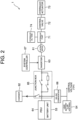
- FIG. 2 is a block diagram schematically illustrating configurations of an electric system and a hydraulic system of the hydraulic excavator 1.
- the hydraulic excavator 1 includes the electric motor 61, a charger 62, an inverter 63, a Power Drive Unit (PDU) 64, a junction box 65, and a DC-DC converter 66, and the system controller 67.
- the system controller 67 is composed of an electronic control unit which is also referred to as an ECU (Electronic Control Unit), and electrically controls each part of the hydraulic excavator 1.
- ECU Electronic Control Unit
- the electric motor 61 is driven by electric power supplied from each battery unit 53 via the junction box 65 and the inverter 63.
- the electric motor 61 is composed of a permanent magnet motor or an induction motor.
- the electric motor 61 is disposed on the turning frame 42 (see FIG. 1 ).
- the charger 62 (also referred to as a power supplier) converts an AC voltage supplied from the commercial power source 51, illustrated in FIG. 1 , via the power supply cable 52 into a DC voltage.
- the inverter 63 converts a DC voltage supplied from the battery units 53 into an AC voltage and supplies the AC voltage to the electric motor 61. Consequently, the electric motor 61 is rotated.
- the AC voltage (current) is supplied from the inverter 63 to the electric motor 61 on the basis of a rotation command output from the system controller 67.
- the PDU 64 is a battery control unit that controls an internal battery relay to control inputting and outputting of the battery units 53.
- the junction box 65 includes a charger relay, an inverter relay, a fuse and the like. The voltage output from the charger 62 is supplied to the battery unit 53 via the junction box 65 and the PDU 64. Further, the voltage output from the battery units 53 is supplied to the inverter 63 via the PDU 64 and the junction box 65.
- the DC-DC converter 66 lowers a high-voltage (300 V, for example) DC voltage supplied from the battery units 53 via the junction box 65 to a low voltage (12 V, for example). Similar to the output from the lead battery 54, the voltage output from the DC-DC converter 66 is supplied to the system controller 67, the drive unit of the fan 81, and the like.
- a plurality of the hydraulic pumps 71 is connected to a rotation shaft (output shaft) of the electric motor 61.
- the plurality of hydraulic pumps 71 include a variable displacement pump and a fixed displacement pump.
- FIG. 2 illustrates only the single hydraulic pump 71 as an example.
- Each hydraulic pump 71 is connected to a hydraulic oil tank 74 that contains (stores) hydraulic oil.
- the control valve 72 is a direction switching valve that controls the flow direction and the flow rate of the hydraulic oil to be supplied to the hydraulic actuator 73.
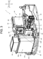
- FIG. 3 is a perspective view illustrating an internal configuration of the engine room 44 of the hydraulic excavator 1.
- the hydraulic excavator 1 includes the fan 81.
- the fan 81 takes outside air into the inside of the machine body by rotation. That is, the fan 81 of this embodiment is of a suction type.
- a rotation shaft of the fan 81 extends in the left-right direction of the machine body.
- the hydraulic pumps 71 are located below the fan 81. Each hydraulic pump 71 is connected to the hydraulic oil tank 74 (see FIG. 2 ) via a hydraulic hose (not illustrated).
- the hydraulic excavator 1 includes a radiator 82.
- the radiator 82 is a heat exchanger that cools a heat exchange medium by heat exchange.
- the heat exchange medium is, for example, cooling water, but may be a refrigerant other than cooling water.
- the radiator 82 is disposed on the right side of the machine body with respect to the fan 81.
- An oil cooler 83 is disposed on the left side of the machine body with respect to the fan 81, that is, on the side opposite to the radiator 82 with respect to the fan 81.
- the oil cooler 83 is connected to an oil path through which oil circulates via the hydraulic pumps 71, the hydraulic actuator 73 (see FIG. 2 ), and the like.
- the oil cooler 83 cools, by heat exchange, the hydraulic oil flowing in the oil path by driving of the hydraulic pump 71.
- the oil cooler 83 is disposed so as to overlap with a portion of the fan 81 when viewed from the rotation shaft direction of the fan 81.
- a wind guide part 84 is disposed on the left side of the machine body with respect to the oil cooler 83, that is, on the side opposite to the fan 81 with respect to the oil cooler 83.
- the electric motor 61 is disposed below the wind guide part 84.
- the hydraulic pump 71 is disposed on the right side of the machine body with respect to the electric motor 61.
- the fan 81 is of a suction type as described above, and therefore when the fan 81 is rotated, outside air is sucked from the outside of the machine body toward the inside of the machine body, flows through the inside of the wind guide part 84, and is discharged to the outside of the machine body.
- the radiator 82 and the oil cooler 83 are disposed in the middle of a flow path of the outside air, and therefore the radiator 82 and the oil cooler 83 are sequentially cooled by the sucked outside air.
- the electric motor 61 is disposed below the wind guide part 84, and therefore the electric motor 61 is cooled by wind discharged from the wind guide part 84.
- the charger 62 and the DC-DC converter 66 are disposed on a side wall of the wind guide part 84, and therefore the charger 62 and the DC-DC converter 66 are also cooled by wind flowing inside the wind guide part 84.
- the arrangement of the fan 81, the radiator 82, and the oil cooler 83 described above is an example, and is not limited to the arrangement of this embodiment. Therefore, the arrangement of the fan 81, the radiator 82, and the oil cooler 83 is devised, so that the fan 81 can be configured as a discharge type to cool the radiator 82 and the oil cooler 83.
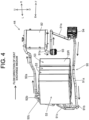
- FIG. 4 is a perspective view of a main part in the engine room 44 illustrated in FIG. 3 when viewed from the right back.
- FIG. 5 is a perspective view of the main part as viewed from the left back side.
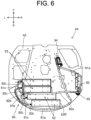
- FIG. 6 is a plan view of the main part.
- the above main part refers to a pipe 90 through which the heat exchange medium flows and a member to which the pipe 90 is connected.
- the hydraulic excavator 1 includes a plurality of the battery units 53 described above.
- the hydraulic excavator 1 includes the four battery units 53, but the number of the battery units 53 is not particularly limited.
- the four battery units 53 are supported in a vibration-proof manner on the turning frame 42 such that the longitudinal direction of each battery unit 53 is the machine body left-right direction in a plan view, and are arranged side by side in the machine body front-back direction.
- the battery units 53 and the radiator 82 are connected by the pipe 90.
- the hydraulic excavator 1 includes the pipe 90 which is connected to the battery units 53 and through which the heat exchange medium flow, and the radiator 82 as a heat exchanger to which the pipe 90 is connected.
- the pipe 90 is formed of, for example, a resin hose, but may be configured to at least partially include a metal pipe, a metal joint, or the like. A detailed configuration of the pipe 90 will be described later.
- each battery unit 53 has a connection port 530 on a left side surface 53L.
- the pipe 90 is connected to the connection ports 530. That is, each battery unit 53 has the connection port 530 to which the pipe 90 is connected, on the left side surface 53L which is one side surface thereof.
- the radiator 82 is disposed on the side (for example, the right side of the machine body) opposite to the side (for example, the left side of the machine body) of the battery units 53 which is connected to the pipe 90, with respect to the battery units 53.
- maintenance of the battery units 53 can be performed from the side opposite to the side on which the radiator 82 is disposed (from the left side of the vehicle body).
- the maintenance of the battery units 53 can be performed by removing a left bonnet (not illustrated) serving as the side wall of the engine room 44. In this case, the above maintenance can be performed without being hindered by the radiator 82, and therefore the maintenance is facilitated.
- the maintenance includes connection and disconnection of the pipe 90 to and from the battery units 53, inspection and confirmation of the connection part between each battery unit 53 and the pipe 90, and the like.
- the maintenance of each battery unit 53 can be performed from the side of the left side surface 53L on which the connection port 530 is provided.
- the radiator 82 is disposed on the side surface (right side surface 53L) side opposite to the above one side surface (left side surface 53R) of each battery unit 53 (in particular, see FIG. 4 and FIG. 6 ).
- the connection port 530 of each battery unit 53 includes a first connection port 531 and a second connection port 532. Both the first connection port 531 and the second connection port 532 are provided on the left side surface 53L of each battery unit 53. On each left side surface 53L, the first connection port 531 and the second connection port 532 are disposed side by side in the up-down direction. Specifically, the second connection port 532 is located above the first connection port 531.
- the plurality of connection ports 530 each including the first connection port 531 and the second connection port 532 are provided on the same side surface (the left side surface 53L in the above example) of each battery unit 53.
- the first connection port 531 and the second connection port 532 are connected to one end and the other end of a circuit for circulating the heat exchange medium in each battery unit 53, respectively.
- the first connection port 531 and the second connection port 532 are located on the same side surface (the left side surface 53L) of each battery unit 53, and the heat exchange medium can be made to flow into each battery unit 53 from the same side surface side and can be discharged from each battery unit 53 to the same side surface side. Consequently, the configuration of the connection side of the pipe 90 with respect to each battery unit 53 can be made compact by using short pipes (for example, a plurality of first individual pipes 91c and a plurality of second individual pipes 92c which will be described later).
- first connection port 531 and the second connection port 532 are respectively connected to one end and the other end of the circuit for circulating the heat exchange medium in each battery unit 53 as in this embodiment, from the viewpoint that the circuit for cooling the plurality of battery units 53 can be realized by simple routing of the pipe 90.
- the number of the battery units 53 may be one. Even in this case, it is possible to realize a circuit for cooling the battery unit 53 with simple routing of the pipe 90 by disposing the first connection port 531 on the inlet side and the second connection port 532 on the outlet side on one side surface (for example, the left side surface 53L) of the battery unit 53.
- the maintenance of the battery units 53 can be collectively performed from the same side (for example, the left side of the machine body), which is desirable from the viewpoint that the maintenance of the battery units 53 can be efficiently performed.
- the pipe 90 is connected to each of the plurality of battery units 53 on the same side.
- the plurality of battery units 53 in which the connection ports 530 with the pipe 90 are provided
- the one side surface for example, the left side surface 53L of each battery unit 53 is directed in the same direction (the left direction of the machine body in FIG. 5 and FIG. 6 ).
- the pipe 90 has a first common pipe 91a that extends from the radiator 82, and the first individual pipes 91c connected to the first common pipe 91a via a branch part 91b.
- a plurality of the first individual pipes 91c are provided corresponding to the respective battery units 53, and extend from the respective first connection ports 531 of the plurality of battery units 53.
- a circulation pump 93 and a heater 94 which will be described later are disposed in the middle of the first common pipe 91a.
- the pipe 90 further has a second common pipe 92a that extends from the radiator 82, and the second individual pipes 92c connected to the second common pipe 92a via a merge part 92b.
- the plurality of second individual pipes 92c are provided corresponding to the respective battery units 53, and extend from the respective second connection ports 532 of the plurality of battery units 53.
- the heat exchange medium discharged from the radiator 82 flows through the first common pipe 91a, is equally distributed into the four first individual pipes 91c at the branch part 91b, flows into the corresponding battery units 53 from the respective first individual pipes 91c via the first connection ports 531, and cools the battery units 53.
- the heat exchange medium that flows inside each battery unit 53 flows from the second connection port 532 into the merge part 92b via the second individual pipes 92c, merges with the heat exchange medium flowing from each of the other battery units 53 via the corresponding second individual pipes 92c at the merge part 92b, and then flows in the second common pipe 92a to return to the radiators 82. Thereafter, such circulation of the heat exchange medium is repeated.
- the temperature adjustment for example, cooling
- the second common pipe 92a is located above the battery units 53 in that the air in the battery units 53 easily escapes upward and the air is less likely to be accumulated in the battery units 53.
- the first common pipe 91a is routed so as to pass through the back side of the machine body of the battery units 53. That is, it is desirable that the first common pipe 91a is routed to pass through the outside of the battery units 53 (to be shifted from the battery units 53) when viewed from above.
- the circulation pump 93 is disposed in the middle of the pipe 90 (particularly, the first common pipe 91a).
- the circulation pump 93 sucks the heat exchange medium cooled by the radiator 82 and pushes the heat exchange medium toward the battery units 53.
- the circulation pump 93 is disposed below the radiator 82 and disposed on the right side of the machine body with respect to the battery units 53.
- the circulation pump 93 is disposed on the back side of the machine body with respect to the radiator 82, but may be disposed on the front side of the machine body with respect to the radiator 82.
- the heat exchange medium After flowing through each battery unit 53, the heat exchange medium absorbs the heat of each battery unit 53 and the temperature of the heat exchange medium rises.
- the circulation pump 93 When the high-temperature heat exchange medium is directly supplied to the circulation pump 93, the circulation pump 93 may be damaged. From the viewpoint of protecting the circulation pump 93 by avoiding damage to the circulation pump 93 due to the supply of the high-temperature heat exchange medium, it is desirable to supply the heat exchange medium cooled by the radiator 82 to the circulation pump 93.
- the circulation pump 93 is disposed in the middle of the first common pipe 91a through which the heat exchange medium flows from the radiator 82 toward the battery units 53. That is, it is desirable that the circulation pump 93 is disposed on the downstream side in the flow direction of the heat exchange medium with respect to the radiator 82.
- the heater 94 is further disposed in the middle of the pipe 90.
- the heater 94 is disposed on the downstream side in the flow direction of the heat exchange medium with respect to the circulation pump 93.
- the heater 94 is disposed on the front side of the machine body with respect to the radiator 82, but may be disposed on the back side of the machine body.
- the fan 81 In a state in which the heater 94 is turned off (non-energized state), the fan 81 (see FIG. 3 ) is driven to apply outside air to the radiator 82, so that the heat exchange medium flowing through the radiator 82 can be cooled by heat exchange. In this case, the heat exchange medium at a relatively low temperature can be supplied to the battery unit 53 by the circulation pump 93 to cool the battery units 53.
- the heater 94 when the heater 94 is energized and turned on in a state in which the driving of the fan 81 is stopped, the heat exchange medium supplied by the circulation pump 93 is heated by the heater 94 and supplied to the battery units 53, so that the battery units 53 can be heated. Therefore, from the viewpoint of enabling the battery units 53 to be used in an appropriate temperature range in cold weather, it is desirable that the heater 94 is disposed in the middle of the pipe 90 as in this embodiment.
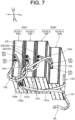
- FIG. 7 is a perspective view illustrating another example of the routing of the pipe 90 in the hydraulic excavator 1.
- FIG. 8 and FIG. 9 are block diagrams each schematically illustrating a configuration of a hydraulic excavator 1 in which a pipe 90 is routed as illustrated in FIG. 7 .
- FIG. 8 also illustrates the flow direction of a heat exchange medium during cooling of battery units 53.
- FIG. 9 also illustrates the flow direction of the heat exchange medium during heating of the battery units 53.
- the configuration is the same as the configuration illustrated in FIG. 4 and the like in that a plurality of (for example, four) the battery units 53 mounted on the hydraulic excavator 1 are arranged side by side in the machine body front-back direction.
- the configuration is the same as the configuration illustrated in FIG. 4 and the like in that each battery unit 53 has a plurality of connection ports 530 (a first connection port 531 and a second connection port 532) on a left side surface 53L. Therefore, also in the configuration illustrated in FIG. 7 , the plurality of battery units 53 (provided with the plurality of connection ports 530) are arranged such that one side surface (for example, the left side surface 53L) of each battery unit is directed in the same direction (for example, the machine body left direction).
- the four battery units 53 arranged in the machine body front-back direction are also referred to as a first battery unit 53-1, a second battery unit 53-2, a third battery unit 53-3, and a fourth battery unit 53-4 in order from the front side of the machine body toward the back side of the machine body.
- the first battery unit 53-1 and the second battery unit 53-2 constitute a first battery group 53G1.
- the third battery unit 53-3 and the fourth battery unit 53-4 constitute a second battery group 53G2. That is, the hydraulic excavator 1 includes the first battery group 53G1 having the plurality of battery units 53 and the second battery group 53G2 having the plurality of battery units 53.
- the pipe 90 through which a heat exchange medium flows is connected to each battery unit 53.
- the pipe 90 includes a first pipe 101, a second pipe 102, a third pipe 103, and a fourth pipe 104.
- the first pipe 101 includes a first connection pipe 101a extending from a temperature adjustment circuit 200 (see FIG. 8 and FIG. 9 ) and a second connection pipe 101c connected to the first connection pipe 101a via a first connection part 101b.
- the second connection pipe 101c are provided corresponding to the second battery unit 53-2 and the third battery unit 53-3, and extend from the first connection port 531 of the second battery unit 53-2 and the first connection port 531 of the third battery unit 53-3, respectively. That is, the first pipe 101 connects any one of the battery units 53 included in the first battery group 53G1 (herein, the second battery unit 53-2) and any one of the battery units 53 included in the second battery group 53G2 (herein, the third battery unit 53-3) to the temperature adjustment circuit 200.
- the temperature adjustment circuit 200 adjusts the temperature of a heat exchange medium flowing through the pipe 90. That is, the hydraulic excavator 1 includes the temperature adjustment circuit 200. Details of the temperature adjustment circuit 200 will be described later.
- the second pipe 102 connects the first connection port 531 of the first battery unit 53-1 and the second connection port 532 of the second battery unit 53-2. That is, the second pipe 102 connects the plurality of battery units 53 (herein, the first battery unit 53-1 and the second battery unit 53-2) included in the first battery group 53G1 in series.
- the third pipe 103 connects the second connection port 532 of the third battery unit 53-3 and the first connection port 531 of the fourth battery unit 53-4. That is, the third pipe 103 connects the plurality of battery units 53 (herein, the third battery unit 53-3 and the fourth battery unit 53-4) included in the second battery group 53G2 in series.
- the fourth pipe 104 includes a third connection pipe 104a extending from the temperature adjustment circuit 200 and a fourth connection pipe 104a connected to the third connection pipe 104c via a second connection part 104b.
- Fourth connection pipes 104c are provided corresponding to the first battery unit 53-1 and the fourth battery unit 53-4, and extend from the second connection port 532 of the first battery unit 53-1 and the second connection port 532 of the fourth battery unit 53-4, respectively. That is, the fourth pipe 104 connects the other battery unit 53 (herein, the first battery unit 53-1) included in the first battery group 53G1 and the other battery unit 53 (herein, the fourth battery unit 53-4) included in the second battery group 53G2 to the temperature adjustment circuit 200.
- the pipe 90 is configured as described above, so that when the heat exchange medium is supplied from the temperature adjustment circuit 200 to the first pipe 101, the heat exchange medium is divided into a first route and a second route, is guided to the fourth pipe 104, and returns to the temperature adjustment circuit 200.
- the first route is a route in which the heat exchange medium flows from the first pipe 101 to the fourth pipe 104 through the second battery unit 53-2, the second pipe 102, and the first battery unit 53-1.
- the second route is a route in which the heat exchange medium flows from the first pipe 101 to the fourth pipe 104 through the third battery unit 53-3, the third pipe 103, and the fourth battery unit 53-4.
- the heat exchange medium flows through the battery units 53 (the second battery unit 53-2 and the third battery unit 53-3) located on the inner side in the machine body front-back direction, before flowing through the battery units 53 (the first battery unit 53-1 and the fourth battery unit 53-4) located on the outer side in the machine body front-back direction among the plurality of battery units 53. Therefore, it is possible to preferentially adjust (for example, cool) the temperatures of the battery units 53 located on the inner side in the machine body front-back direction.
- the heat exchange medium when the heat exchange medium is supplied from the temperature adjustment circuit 200 to the fourth pipe 104, the heat exchange medium is divided into a third route and a fourth route, guided to the first pipe 101, and returns to the temperature adjustment circuit 200.
- the third route is a route in which the heat exchange medium flows from the fourth pipe 104 to the first pipe 101 through the first battery unit 53-1, the second pipe 102, and the second battery unit 53-2.
- the fourth route is a route in which the heat exchange medium flows from the fourth pipe 104 to the first pipe 101 through the fourth battery unit 53-4, the third pipe 103, and the third battery unit 53-3.
- the heat exchange medium flows through the battery units 53 (the first battery unit 53-1 and the fourth battery unit 53-4) located on the outer side in the machine body front-back direction, before flowing through the battery units 53 (the second battery unit 53-2 and the third battery unit 53-3) located on the inner side in the machine body front-back direction among the plurality of battery units 53. Therefore, the temperatures of the battery units 53 located on the outer side in the machine body front-back direction can be preferentially adjusted (for example, heated).
- the configuration of the pipe 90 illustrated in FIG. 7 is desirable in that the temperature adjustment of some of the battery units 53 among the plurality of battery units 53 can be performed more preferentially than the other battery units 53.
- the adjacent battery units 53 (the first battery unit 53-1 and the second battery unit 53-2) included in the first battery group 53G1 can be connected by the short second pipe 102.
- the adjacent battery units 53 (the third battery unit 53-3 and the fourth battery unit 53-4) included in the second battery group 53G2 can be connected to each other by the short third pipe 103. Consequently, the layout of the pipe 90 can be made compact, and also in this respect, the routing of the pipe 90 illustrated in FIG. 7 is desirable.
- the temperature adjustment circuit 200 includes a switching valve 95 in addition to the radiator 82, the circulation pump 93, and the heater 94 described above.
- the switching valve 95 switches a supply destination of the heat exchange medium from the radiator 82 or the heater 94 between the first pipe 101 and the fourth pipe 104.
- Such a switching valve 95 is composed of, for example, an electromagnetic valve, but may be composed of a valve that switches the supply destination of the heat exchange medium by manual operation.
- the radiator 82 and the heater 94 are disposed in parallel.
- the heat exchange medium flows through the radiator 82 or the heater 94 by the circulation pump 93, and is supplied to the switching valve 95.
- the second battery unit 53-2 to which the first pipe 101 is connected among the plurality of battery units 53 included in the first battery group 53G1 and the third battery unit 53-3 to which the first pipe 101 is connected among the plurality of battery units 53 included in the second battery group 53G2 are each defined as a first pipe connection battery unit 53P.
- the other first battery unit 53-1 to which the fourth pipe 104 is connected among the plurality of battery units 53 included in the first battery group 53G1 and the other fourth battery unit 53-4 to which the fourth pipe 104 is connected among the plurality of battery units 53 included in the second battery group 53G2 are each defined as a fourth pipe connection battery unit 53Q.
- the two first pipe connection battery units 53P are disposed between the two fourth pipe connection battery units 53Q in the machine body front-back direction.
- the battery units 53 In a case where the plurality of battery units 53 are arranged side by side in the machine body front-back direction, when each of the battery units 53 generates heat due to use, heat dissipation is likely to progress in the battery units 53 (for example, the first battery unit 53-1 and the fourth battery unit 53-4) located near both ends in the alignment direction. On the other hand, in the battery units 53 (for example, the second battery unit 53-2 and the third battery unit 53-3) located near the center in the alignment direction, heat dissipation does not easily proceed, and heat is likely to be confined.
- the two first pipe connection battery units 53P are disposed between the two fourth pipe connection battery units 53Q. Consequently, the (low-temperature) heat transfer medium immediately after being cooled by the radiators 82 included in the temperature adjustment circuit 200 can be supplied to the first pipe connection battery units 53P via the first pipe 101 before being supplied to the fourth pipe connection battery units 53Q, so that the first pipe connection battery units 53P in which heat is likely to be confined can be preferentially cooled.
- the battery units 53 (for example, the first battery unit 53-1 and the fourth battery unit 53-4) located near the both ends in the alignment direction are more likely to be deprived of heat and to decrease in the temperatures than the battery units 53 (for example, the second battery unit 53-2 and the third battery unit 53-3) located near the center in the alignment direction.
- the two fourth pipe connection battery units 53Q are located outside the two first pipe connection battery units 53P in the alignment direction. Therefore, the heat exchange medium heated by the heater 94 can be supplied to the fourth pipe connection battery units 53Q via the fourth pipe 104 before being supplied to the first pipe connection battery units 53P, so that the fourth pipe connection battery units 53Q, the temperatures of which are likely to be lowered in cold weather, can be preferentially heated.
- the two first pipe connection battery units 53P are disposed between the two fourth pipe connection battery units 53Q, from the viewpoint of switching the battery units 53 to which the heat exchange medium is preferentially supplied in consideration of the difference in the degree of heat dissipation depending on the arrangement positions of the plurality of battery units 53, realizing a uniform temperature in the plurality of battery units 53 as a whole, and making the degree of deterioration of the battery units 53 uniform.
- the switching valve 95 switches the supply destination of the heat exchange medium cooled by the radiator 82 to the first pipe 101 when the respective battery units 53 included in the first battery group 53G1 and the second battery group 53G2 are cooled.
- the switching valve 95 switches the supply destination of the heat exchange medium heated by the heater 94 to the fourth pipes 104 when the battery units 53 are heated.
- the hydraulic excavator 1 which is a construction machine is described above as an example of a work machine
- the work machine is not limited to the hydraulic excavator 1, and may be another construction machine such as a wheel loader.
- the work machine may be an agricultural machine such as a combine and a tractor.
- the hydraulic excavator 1 described in this embodiment can also be expressed as a work machine as described in the following appendices.
- a work machine of Appendix (1) includes:
- the first common pipe is routed to pass through outside of the battery units as viewed from above.
- Appendix 10 the work machine mentioned in Appendix (2) or Appendix (3) comprising:
- the switching valve switches the supply destination of the heat exchange medium heated by the heater to the fourth pipe when the battery units are heated.
- the present invention can be used for a work machine such as a construction machine and an agricultural machine, for example.
Landscapes
- Engineering & Computer Science (AREA)
- Chemical & Material Sciences (AREA)
- Chemical Kinetics & Catalysis (AREA)
- Electrochemistry (AREA)
- General Chemical & Material Sciences (AREA)
- Manufacturing & Machinery (AREA)
- Mechanical Engineering (AREA)
- Power Engineering (AREA)
- Transportation (AREA)
- Mining & Mineral Resources (AREA)
- Civil Engineering (AREA)
- Structural Engineering (AREA)
- General Engineering & Computer Science (AREA)
- Life Sciences & Earth Sciences (AREA)
- Sustainable Development (AREA)
- Sustainable Energy (AREA)
- Combustion & Propulsion (AREA)
- Automation & Control Theory (AREA)
- Physics & Mathematics (AREA)
- Thermal Sciences (AREA)
- Cooling, Air Intake And Gas Exhaust, And Fuel Tank Arrangements In Propulsion Units (AREA)
- Arrangement Or Mounting Of Propulsion Units For Vehicles (AREA)
- Component Parts Of Construction Machinery (AREA)
- Operation Control Of Excavators (AREA)
Abstract
[Problem] To provide a work machine enabling easy maintenance of a battery unit.[Solution] A work machine includes a battery unit, a pipe which is connected to the battery unit and through which a heat exchange medium flows, and a heat exchanger to which the pipe is connected. The heat exchanger is disposed on a side opposite to a side of the battery unit which is connected to the pipe, with respect to the battery unit.
Description
- The present invention relates to a work machine.
- Conventionally, there is proposed an electric hydraulic excavator in which a plurality of air-cooled battery units are disposed in a box body (see Patent Document 1, for example).
- Patent Document 1: International Publication No.
WO2021/059514 - In a configuration for air-cooling a battery unit, it is difficult to adjust (for example, cool) the temperature of a battery unit to an appropriate temperature range in a short time. Therefore, in recent years, a water-cooling method using a heat exchange medium such as cooling water is often employed as a method for cooling the battery unit. A pipe that circulates a heat exchange medium between a heat exchanger such as a radiator and the battery unit is provided, so that the battery unit can be cooled to an appropriate temperature in a short time.
- However, in a case where the water-cooling method is employed, for example, when the connection part of the battery unit to the pipe is located on the heat exchanger side, maintenance such as inspection of the connection part may be difficult to perform due to presence of the heat exchanger.
- The present invention has been made to solve the above-described problem, and an object of the present invention is to provide a work machine capable of facilitating maintenance of a battery unit.
- A work machine according to one aspect of the present invention includes: a battery unit; a pipe which is connected to the battery unit and through which a heat exchange medium flows; and a heat exchanger to which the pipe is connected, and the heat exchanger is disposed on a side opposite to a side of the battery unit which is connected to the pipe, with respect to the battery unit.
- According to the above configuration, it is possible to facilitate maintenance of a battery unit.
-
-
FIG. 1 is a side view illustrating a schematic configuration of a hydraulic excavator which is an example of an electric work machine according to an embodiment of the present invention; -
FIG. 2 is a block diagram schematically illustrating a configuration of an electric system and a hydraulic system of the hydraulic excavator; -
FIG. 3 is a perspective view illustrating an internal configuration of an engine room of the hydraulic excavator; -
FIG. 4 is a perspective view of a main part in the engine room as viewed from the right back side; -
FIG. 5 is a perspective view of the main part as viewed from the left back side; -
FIG. 6 is a plan view of the main part; -
FIG. 7 is a perspective view illustrating another example of routing of a pipe in the hydraulic excavator; -
FIG. 8 is a block diagram illustrating a configuration of the hydraulic excavator in which the pipe is routed as illustrated inFIG. 7 , together with the flow direction of a heat exchange medium during cooling of the battery unit; and -
FIG. 9 is a block diagram illustrating the configuration of the hydraulic excavator together with the flow direction of the heat exchange medium during heating of the battery unit. - The following is description of embodiments of the present invention based on the drawings.
-
FIG. 1 is a side view illustrating a schematic configuration of an electric hydraulic excavator 1 which is an example of a work machine of this embodiment. The hydraulic excavator 1 includes alower traveling body 2, a work machine 3, and an upper turningbody 4. In this embodiment, the hydraulic excavator 1 or the upper turning body 4 (particularly, an engine room 44) is also referred to as a "machine body". - For convenience of the following description, directions are defined as follows. The direction in which an operator (a manipulator, a driver) seated on a driver's
seat 41a of the upper turningbody 4 faces front is defined as the forward direction, and the direction opposite to the forward direction is defined as the backward direction. Therefore, in a state in which the upper turningbody 4 does not turn with respect to the lower traveling body 2 (turning angle: 0°), a front-back direction of the upper turningbody 4 coincides with the direction in which the lower travelingbody 2 moves forward and backward. As viewed from the operator seated on the driver'sseat 41a, the left side is defined as the "left" and the right side is defined as the "right". The gravity direction perpendicular to the front-back direction and the left-right direction is defined as the up-down direction, in which the upstream side of the gravity direction is defined as the "up", and the downstream side thereof is defined as the "down". In the drawings, the hydraulic excavator 1 is illustrated in a state in which the upper turningbody 4 does not turn with respect to thelower traveling body 2. Further, in the drawings, when necessary, the forward direction is denoted by "F", the backward direction is denoted by "B", the rightward direction is denoted by "R", the leftward direction is denoted by "L", the upward direction is denoted by "U", and the downward direction is denoted by "D". - The
lower traveling body 2 includes a pair of left andright crawlers 21 and a pair of left andright traveling motors 22. Each of thetraveling motors 22 is a hydraulic motor. The left and righttraveling motors 22 drive the left andright crawlers 21, respectively, so that the hydraulic excavator 1 can be moved forward and backward. The lower travelingbody 2 is provided with ablade 23 for performing ground leveling work and ablade cylinder 23a. Theblade cylinder 23a is a hydraulic cylinder that rotates theblade 23 in the up-down direction. - The work machine 3 includes a
boom 31, anarm 32, and abucket 33. Theboom 31, thearm 32, and thebucket 33 are independently driven, so that it is possible to perform excavation work of earth, sand, and the like. - The
boom 31 is rotated by theboom cylinder 31a. Theboom cylinder 31a has a base end supported by a front part of the upper turningbody 4, and is movable freely in an extendable and retractable manner. Thearm 32 is rotated by anarm cylinder 32a. Thearm cylinder 32a has a base end supported by theboom 31, and is movable freely in an extendable and retractable manner. Thebucket 33 is rotated by abucket cylinder 33a. Thebucket cylinder 33a has a base end supported by thearm 32, and is movable freely in an extendable and retractable manner. Theboom cylinder 31a, thearm cylinder 32a, and thebucket cylinder 33a are each composed of a hydraulic cylinder. - The upper turning
body 4 is located above the lower travelingbody 2, and is provided so as to be turnable via a turning bearing (not illustrated) with respect to the lower travelingbody 2. In the upper turningbody 4, asteering part 41, aturning frame 42, a turningmotor 43, anengine room 44, and the like are disposed. The upper turningbody 4 turns via the turning bearing by the driving of the turningmotor 43 which is a hydraulic motor. - In the upper turning
body 4, hydraulic pumps 71 (seeFIG. 2 ) are disposed. Thehydraulic pumps 71 are driven by an electric motor 61 (seeFIG. 2 ) inside theengine room 44. Thehydraulic pumps 71 supply hydraulic oil (pressure oil) to hydraulic motors (for example, the left andright traveling motors 22 and the turning motor 43), and hydraulic cylinders (for example, theblade cylinder 23a, theboom cylinder 31a, thearm cylinder 32a, and thebucket cylinder 33a). The hydraulic motors and the hydraulic cylinders that are driven with the hydraulic oil supplied from thehydraulic pumps 71 are collectively referred to as a hydraulic actuator 73 (seeFIG. 2 ). - In the
steering part 41, the driver'sseat 41a is disposed.Various levers 41b are disposed around the driver'sseat 41a. An operator is seated on the driver'sseat 41a and operates thelevers 41b, so that thehydraulic actuator 73 is driven. Consequently, it is possible to perform traveling of thelower traveling body 2, ground leveling work by theblade 23, excavation work by the work machine 3, turning of theupper turning body 4, and the like. - In the
upper turning body 4,battery units 53 are disposed. Eachbattery unit 53 is composed of, for example, a lithium-ion battery unit, and stores electric power for driving theelectric motor 61. Thebattery unit 53 may be composed of a plurality of batteries as a unit or may be composed of a single battery cell. In theupper turning body 4, a power supply port, not illustrated, is provided. The power supply port and acommercial power source 51 which is an external power source are connected via apower supply cable 52. Consequently, thebattery unit 53 can be charged. - In the
upper turning body 4, alead battery 54 is further provided. Thelead battery 54 outputs a low-voltage (12 V, for example) DC voltage. The output from thelead battery 54 is supplied as a control voltage to, for example, a system controller 67 (seeFIG. 2 ), a drive unit of a fan 81 (seeFIG. 3 and the like), and the like. - The hydraulic excavator 1 may be configured to be a combination of a hydraulic device such as the
hydraulic actuator 73 and an actuator driven by electric power. Examples of the actuator driven by electric power include an electric traveling motor, an electric cylinder, and an electric turning motor. -
FIG. 2 is a block diagram schematically illustrating configurations of an electric system and a hydraulic system of the hydraulic excavator 1. The hydraulic excavator 1 includes theelectric motor 61, acharger 62, aninverter 63, a Power Drive Unit (PDU) 64, ajunction box 65, and a DC-DC converter 66, and thesystem controller 67. Thesystem controller 67 is composed of an electronic control unit which is also referred to as an ECU (Electronic Control Unit), and electrically controls each part of the hydraulic excavator 1. - The
electric motor 61 is driven by electric power supplied from eachbattery unit 53 via thejunction box 65 and theinverter 63. Theelectric motor 61 is composed of a permanent magnet motor or an induction motor. Theelectric motor 61 is disposed on the turning frame 42 (seeFIG. 1 ). - The charger 62 (also referred to as a power supplier) converts an AC voltage supplied from the
commercial power source 51, illustrated inFIG. 1 , via thepower supply cable 52 into a DC voltage. Theinverter 63 converts a DC voltage supplied from thebattery units 53 into an AC voltage and supplies the AC voltage to theelectric motor 61. Consequently, theelectric motor 61 is rotated. The AC voltage (current) is supplied from theinverter 63 to theelectric motor 61 on the basis of a rotation command output from thesystem controller 67. - The
PDU 64 is a battery control unit that controls an internal battery relay to control inputting and outputting of thebattery units 53. Thejunction box 65 includes a charger relay, an inverter relay, a fuse and the like. The voltage output from thecharger 62 is supplied to thebattery unit 53 via thejunction box 65 and thePDU 64. Further, the voltage output from thebattery units 53 is supplied to theinverter 63 via thePDU 64 and thejunction box 65. - The DC-
DC converter 66 lowers a high-voltage (300 V, for example) DC voltage supplied from thebattery units 53 via thejunction box 65 to a low voltage (12 V, for example). Similar to the output from thelead battery 54, the voltage output from the DC-DC converter 66 is supplied to thesystem controller 67, the drive unit of thefan 81, and the like. - A plurality of the
hydraulic pumps 71 is connected to a rotation shaft (output shaft) of theelectric motor 61. The plurality ofhydraulic pumps 71 include a variable displacement pump and a fixed displacement pump.FIG. 2 illustrates only the singlehydraulic pump 71 as an example. Eachhydraulic pump 71 is connected to ahydraulic oil tank 74 that contains (stores) hydraulic oil. When thehydraulic pump 71 is driven by theelectric motor 61, the hydraulic oil in thehydraulic oil tank 74 is supplied to thehydraulic actuator 73 via acontrol valve 72. Consequently, thehydraulic actuator 73 is driven. Thecontrol valve 72 is a direction switching valve that controls the flow direction and the flow rate of the hydraulic oil to be supplied to thehydraulic actuator 73. -
FIG. 3 is a perspective view illustrating an internal configuration of theengine room 44 of the hydraulic excavator 1. The hydraulic excavator 1 includes thefan 81. Thefan 81 takes outside air into the inside of the machine body by rotation. That is, thefan 81 of this embodiment is of a suction type. A rotation shaft of thefan 81 extends in the left-right direction of the machine body. The hydraulic pumps 71 are located below thefan 81. Eachhydraulic pump 71 is connected to the hydraulic oil tank 74 (seeFIG. 2 ) via a hydraulic hose (not illustrated). - The hydraulic excavator 1 includes a
radiator 82. Theradiator 82 is a heat exchanger that cools a heat exchange medium by heat exchange. The heat exchange medium is, for example, cooling water, but may be a refrigerant other than cooling water. Theradiator 82 is disposed on the right side of the machine body with respect to thefan 81. - An
oil cooler 83 is disposed on the left side of the machine body with respect to thefan 81, that is, on the side opposite to theradiator 82 with respect to thefan 81. Theoil cooler 83 is connected to an oil path through which oil circulates via thehydraulic pumps 71, the hydraulic actuator 73 (seeFIG. 2 ), and the like. Theoil cooler 83 cools, by heat exchange, the hydraulic oil flowing in the oil path by driving of thehydraulic pump 71. - The
oil cooler 83 is disposed so as to overlap with a portion of thefan 81 when viewed from the rotation shaft direction of thefan 81. - A
wind guide part 84 is disposed on the left side of the machine body with respect to theoil cooler 83, that is, on the side opposite to thefan 81 with respect to theoil cooler 83. Theelectric motor 61 is disposed below thewind guide part 84. Thehydraulic pump 71 is disposed on the right side of the machine body with respect to theelectric motor 61. - The
fan 81 is of a suction type as described above, and therefore when thefan 81 is rotated, outside air is sucked from the outside of the machine body toward the inside of the machine body, flows through the inside of thewind guide part 84, and is discharged to the outside of the machine body. Theradiator 82 and theoil cooler 83 are disposed in the middle of a flow path of the outside air, and therefore theradiator 82 and theoil cooler 83 are sequentially cooled by the sucked outside air. In addition, theelectric motor 61 is disposed below thewind guide part 84, and therefore theelectric motor 61 is cooled by wind discharged from thewind guide part 84. Further, as illustrated inFIG. 3 , thecharger 62 and the DC-DC converter 66 are disposed on a side wall of thewind guide part 84, and therefore thecharger 62 and the DC-DC converter 66 are also cooled by wind flowing inside thewind guide part 84. - The arrangement of the
fan 81, theradiator 82, and theoil cooler 83 described above is an example, and is not limited to the arrangement of this embodiment. Therefore, the arrangement of thefan 81, theradiator 82, and theoil cooler 83 is devised, so that thefan 81 can be configured as a discharge type to cool theradiator 82 and theoil cooler 83. -
FIG. 4 is a perspective view of a main part in theengine room 44 illustrated inFIG. 3 when viewed from the right back.FIG. 5 is a perspective view of the main part as viewed from the left back side.FIG. 6 is a plan view of the main part. Herein, the above main part refers to apipe 90 through which the heat exchange medium flows and a member to which thepipe 90 is connected. - As illustrated in
FIG. 4 to FIG. 6 , the hydraulic excavator 1 includes a plurality of thebattery units 53 described above. In this embodiment, the hydraulic excavator 1 includes the fourbattery units 53, but the number of thebattery units 53 is not particularly limited. As illustrated inFIG. 6 , the fourbattery units 53 are supported in a vibration-proof manner on the turningframe 42 such that the longitudinal direction of eachbattery unit 53 is the machine body left-right direction in a plan view, and are arranged side by side in the machine body front-back direction. Thebattery units 53 and theradiator 82 are connected by thepipe 90. That is, the hydraulic excavator 1 includes thepipe 90 which is connected to thebattery units 53 and through which the heat exchange medium flow, and theradiator 82 as a heat exchanger to which thepipe 90 is connected. Thepipe 90 is formed of, for example, a resin hose, but may be configured to at least partially include a metal pipe, a metal joint, or the like. A detailed configuration of thepipe 90 will be described later. - As illustrated in
FIG. 5 , eachbattery unit 53 has aconnection port 530 on aleft side surface 53L. Thepipe 90 is connected to theconnection ports 530. That is, eachbattery unit 53 has theconnection port 530 to which thepipe 90 is connected, on theleft side surface 53L which is one side surface thereof. - As illustrated in
FIG. 5 andFIG. 6 , theradiator 82 is disposed on the side (for example, the right side of the machine body) opposite to the side (for example, the left side of the machine body) of thebattery units 53 which is connected to thepipe 90, with respect to thebattery units 53. With such a positional relationship between theradiator 82 and thebattery units 53, maintenance of thebattery units 53 can be performed from the side opposite to the side on which theradiator 82 is disposed (from the left side of the vehicle body). For example, the maintenance of thebattery units 53 can be performed by removing a left bonnet (not illustrated) serving as the side wall of theengine room 44. In this case, the above maintenance can be performed without being hindered by theradiator 82, and therefore the maintenance is facilitated. The maintenance includes connection and disconnection of thepipe 90 to and from thebattery units 53, inspection and confirmation of the connection part between eachbattery unit 53 and thepipe 90, and the like. - In particular, from a viewpoint of facilitating the maintenance of the
battery units 53 in the vicinities of theconnection ports 530, it is desirable that the maintenance of eachbattery unit 53 can be performed from the side of theleft side surface 53L on which theconnection port 530 is provided. In this respect, as illustrated inFIG. 5 and the like, it is desirable that theradiator 82 is disposed on the side surface (right side surface 53L) side opposite to the above one side surface (leftside surface 53R) of each battery unit 53 (in particular, seeFIG. 4 andFIG. 6 ). - As illustrated in
FIG. 5 , theconnection port 530 of eachbattery unit 53 includes afirst connection port 531 and asecond connection port 532. Both thefirst connection port 531 and thesecond connection port 532 are provided on theleft side surface 53L of eachbattery unit 53. On eachleft side surface 53L, thefirst connection port 531 and thesecond connection port 532 are disposed side by side in the up-down direction. Specifically, thesecond connection port 532 is located above thefirst connection port 531. - From the viewpoint of enabling the maintenance of the
first connection port 531 and thesecond connection port 532 to be collectively performed, it is desirable that the plurality ofconnection ports 530 each including thefirst connection port 531 and thesecond connection port 532 are provided on the same side surface (theleft side surface 53L in the above example) of eachbattery unit 53. - The
first connection port 531 and thesecond connection port 532 are connected to one end and the other end of a circuit for circulating the heat exchange medium in eachbattery unit 53, respectively. In this case, as described above, thefirst connection port 531 and thesecond connection port 532 are located on the same side surface (theleft side surface 53L) of eachbattery unit 53, and the heat exchange medium can be made to flow into eachbattery unit 53 from the same side surface side and can be discharged from eachbattery unit 53 to the same side surface side. Consequently, the configuration of the connection side of thepipe 90 with respect to eachbattery unit 53 can be made compact by using short pipes (for example, a plurality of firstindividual pipes 91c and a plurality of secondindividual pipes 92c which will be described later). Therefore, it is desirable that thefirst connection port 531 and thesecond connection port 532 are respectively connected to one end and the other end of the circuit for circulating the heat exchange medium in eachbattery unit 53 as in this embodiment, from the viewpoint that the circuit for cooling the plurality ofbattery units 53 can be realized by simple routing of thepipe 90. - The number of the
battery units 53 may be one. Even in this case, it is possible to realize a circuit for cooling thebattery unit 53 with simple routing of thepipe 90 by disposing thefirst connection port 531 on the inlet side and thesecond connection port 532 on the outlet side on one side surface (for example, theleft side surface 53L) of thebattery unit 53. - Further, as illustrated in
FIG. 5 andFIG. 6 , in a case where the plurality ofbattery units 53 are arranged side by side on the turningframe 42, the maintenance of thebattery units 53 can be collectively performed from the same side (for example, the left side of the machine body), which is desirable from the viewpoint that the maintenance of thebattery units 53 can be efficiently performed. From this viewpoint, it is desirable that thepipe 90 is connected to each of the plurality ofbattery units 53 on the same side. In other words, it is desirable that the plurality of battery units 53 (in which theconnection ports 530 with thepipe 90 are provided) are disposed such that the one side surface (for example, theleft side surface 53L) of eachbattery unit 53 is directed in the same direction (the left direction of the machine body inFIG. 5 andFIG. 6 ). - Now, the
pipe 90 will be described in detail. As illustrated inFIG. 4 to FIG. 6 , thepipe 90 has a firstcommon pipe 91a that extends from theradiator 82, and the firstindividual pipes 91c connected to the firstcommon pipe 91a via abranch part 91b. A plurality of the firstindividual pipes 91c are provided corresponding to therespective battery units 53, and extend from the respectivefirst connection ports 531 of the plurality ofbattery units 53. Acirculation pump 93 and aheater 94 which will be described later are disposed in the middle of the firstcommon pipe 91a. - The
pipe 90 further has a secondcommon pipe 92a that extends from theradiator 82, and the secondindividual pipes 92c connected to the secondcommon pipe 92a via amerge part 92b. The plurality of secondindividual pipes 92c are provided corresponding to therespective battery units 53, and extend from the respectivesecond connection ports 532 of the plurality ofbattery units 53. - In the above configuration of the
pipe 90, the heat exchange medium discharged from theradiator 82 flows through the firstcommon pipe 91a, is equally distributed into the four firstindividual pipes 91c at thebranch part 91b, flows into the correspondingbattery units 53 from the respective firstindividual pipes 91c via thefirst connection ports 531, and cools thebattery units 53. The heat exchange medium that flows inside eachbattery unit 53 flows from thesecond connection port 532 into themerge part 92b via the secondindividual pipes 92c, merges with the heat exchange medium flowing from each of theother battery units 53 via the corresponding secondindividual pipes 92c at themerge part 92b, and then flows in the secondcommon pipe 92a to return to theradiators 82. Thereafter, such circulation of the heat exchange medium is repeated. - From the viewpoint of making the layout of the
pipe 90 compact, as in this embodiment, it is desirable to adopt a configuration in which the plurality of firstindividual pipes 91c connected to thebattery units 53 are connected to the single firstcommon pipe 91a via thebranch part 91b, and the plurality of secondindividual pipes 92c connected to thebattery units 53 are connected to the single secondcommon pipe 92a via themerge part 92b. - Further, in order to efficiently perform the temperature adjustment (for example, cooling) of the
battery unit 53 by the heat exchange medium, it is desirable to fill the inside of eachbattery unit 53 with the heat exchange medium. For this purpose, it is desirable that air existing in thebattery units 53 can easily escape to the outside of thebattery units 53. As illustrated inFIG. 4 andFIG. 5 , it is desirable that the secondcommon pipe 92a is located above thebattery units 53 in that the air in thebattery units 53 easily escapes upward and the air is less likely to be accumulated in thebattery units 53. - From the viewpoint of effectively using space around the
battery units 53 as routing space for the firstcommon pipe 91a, thebranch part 91b, and the firstindividual pipes 91c, as illustrated inFIG. 6 , it is desirable that the firstcommon pipe 91a is routed so as to pass through the back side of the machine body of thebattery units 53. That is, it is desirable that the firstcommon pipe 91a is routed to pass through the outside of the battery units 53 (to be shifted from the battery units 53) when viewed from above. - As illustrated in
FIG. 4 andFIG. 6 , thecirculation pump 93 is disposed in the middle of the pipe 90 (particularly, the firstcommon pipe 91a). Thecirculation pump 93 sucks the heat exchange medium cooled by theradiator 82 and pushes the heat exchange medium toward thebattery units 53. Thecirculation pump 93 is disposed below theradiator 82 and disposed on the right side of the machine body with respect to thebattery units 53. Thecirculation pump 93 is disposed on the back side of the machine body with respect to theradiator 82, but may be disposed on the front side of the machine body with respect to theradiator 82. - After flowing through each
battery unit 53, the heat exchange medium absorbs the heat of eachbattery unit 53 and the temperature of the heat exchange medium rises. When the high-temperature heat exchange medium is directly supplied to thecirculation pump 93, thecirculation pump 93 may be damaged. From the viewpoint of protecting thecirculation pump 93 by avoiding damage to thecirculation pump 93 due to the supply of the high-temperature heat exchange medium, it is desirable to supply the heat exchange medium cooled by theradiator 82 to thecirculation pump 93. In this respect, as illustrated inFIG. 4 and the like, it is desirable that thecirculation pump 93 is disposed in the middle of the firstcommon pipe 91a through which the heat exchange medium flows from theradiator 82 toward thebattery units 53. That is, it is desirable that thecirculation pump 93 is disposed on the downstream side in the flow direction of the heat exchange medium with respect to theradiator 82. - In this embodiment, as illustrated in
FIG. 4 , theheater 94 is further disposed in the middle of thepipe 90. In particular, in the firstcommon pipe 91a, theheater 94 is disposed on the downstream side in the flow direction of the heat exchange medium with respect to thecirculation pump 93. Theheater 94 is disposed on the front side of the machine body with respect to theradiator 82, but may be disposed on the back side of the machine body. - In a state in which the
heater 94 is turned off (non-energized state), the fan 81 (seeFIG. 3 ) is driven to apply outside air to theradiator 82, so that the heat exchange medium flowing through theradiator 82 can be cooled by heat exchange. In this case, the heat exchange medium at a relatively low temperature can be supplied to thebattery unit 53 by thecirculation pump 93 to cool thebattery units 53. On the other hand, when theheater 94 is energized and turned on in a state in which the driving of thefan 81 is stopped, the heat exchange medium supplied by thecirculation pump 93 is heated by theheater 94 and supplied to thebattery units 53, so that thebattery units 53 can be heated. Therefore, from the viewpoint of enabling thebattery units 53 to be used in an appropriate temperature range in cold weather, it is desirable that theheater 94 is disposed in the middle of thepipe 90 as in this embodiment. -
FIG. 7 is a perspective view illustrating another example of the routing of thepipe 90 in the hydraulic excavator 1.FIG. 8 andFIG. 9 are block diagrams each schematically illustrating a configuration of a hydraulic excavator 1 in which apipe 90 is routed as illustrated inFIG. 7 .FIG. 8 also illustrates the flow direction of a heat exchange medium during cooling ofbattery units 53.FIG. 9 also illustrates the flow direction of the heat exchange medium during heating of thebattery units 53. - As illustrated in
FIG. 7 , the configuration is the same as the configuration illustrated inFIG. 4 and the like in that a plurality of (for example, four) thebattery units 53 mounted on the hydraulic excavator 1 are arranged side by side in the machine body front-back direction. In addition, the configuration is the same as the configuration illustrated inFIG. 4 and the like in that eachbattery unit 53 has a plurality of connection ports 530 (afirst connection port 531 and a second connection port 532) on aleft side surface 53L. Therefore, also in the configuration illustrated inFIG. 7 , the plurality of battery units 53 (provided with the plurality of connection ports 530) are arranged such that one side surface (for example, theleft side surface 53L) of each battery unit is directed in the same direction (for example, the machine body left direction). - Herein, for convenience of description below, the four
battery units 53 arranged in the machine body front-back direction are also referred to as a first battery unit 53-1, a second battery unit 53-2, a third battery unit 53-3, and a fourth battery unit 53-4 in order from the front side of the machine body toward the back side of the machine body. The first battery unit 53-1 and the second battery unit 53-2 constitute a first battery group 53G1. The third battery unit 53-3 and the fourth battery unit 53-4 constitute a second battery group 53G2. That is, the hydraulic excavator 1 includes the first battery group 53G1 having the plurality ofbattery units 53 and the second battery group 53G2 having the plurality ofbattery units 53. Thepipe 90 through which a heat exchange medium flows is connected to eachbattery unit 53. - As illustrated in
FIG. 7 to FIG. 9 , thepipe 90 includes afirst pipe 101, asecond pipe 102, athird pipe 103, and afourth pipe 104. - The
first pipe 101 includes afirst connection pipe 101a extending from a temperature adjustment circuit 200 (seeFIG. 8 andFIG. 9 ) and asecond connection pipe 101c connected to thefirst connection pipe 101a via afirst connection part 101b. Thesecond connection pipe 101c are provided corresponding to the second battery unit 53-2 and the third battery unit 53-3, and extend from thefirst connection port 531 of the second battery unit 53-2 and thefirst connection port 531 of the third battery unit 53-3, respectively. That is, thefirst pipe 101 connects any one of thebattery units 53 included in the first battery group 53G1 (herein, the second battery unit 53-2) and any one of thebattery units 53 included in the second battery group 53G2 (herein, the third battery unit 53-3) to thetemperature adjustment circuit 200. - The
temperature adjustment circuit 200 adjusts the temperature of a heat exchange medium flowing through thepipe 90. That is, the hydraulic excavator 1 includes thetemperature adjustment circuit 200. Details of thetemperature adjustment circuit 200 will be described later. - The
second pipe 102 connects thefirst connection port 531 of the first battery unit 53-1 and thesecond connection port 532 of the second battery unit 53-2. That is, thesecond pipe 102 connects the plurality of battery units 53 (herein, the first battery unit 53-1 and the second battery unit 53-2) included in the first battery group 53G1 in series. - The
third pipe 103 connects thesecond connection port 532 of the third battery unit 53-3 and thefirst connection port 531 of the fourth battery unit 53-4. That is, thethird pipe 103 connects the plurality of battery units 53 (herein, the third battery unit 53-3 and the fourth battery unit 53-4) included in the second battery group 53G2 in series. - The
fourth pipe 104 includes athird connection pipe 104a extending from thetemperature adjustment circuit 200 and afourth connection pipe 104a connected to thethird connection pipe 104c via asecond connection part 104b.Fourth connection pipes 104c are provided corresponding to the first battery unit 53-1 and the fourth battery unit 53-4, and extend from thesecond connection port 532 of the first battery unit 53-1 and thesecond connection port 532 of the fourth battery unit 53-4, respectively. That is, thefourth pipe 104 connects the other battery unit 53 (herein, the first battery unit 53-1) included in the first battery group 53G1 and the other battery unit 53 (herein, the fourth battery unit 53-4) included in the second battery group 53G2 to thetemperature adjustment circuit 200. - The
pipe 90 is configured as described above, so that when the heat exchange medium is supplied from thetemperature adjustment circuit 200 to thefirst pipe 101, the heat exchange medium is divided into a first route and a second route, is guided to thefourth pipe 104, and returns to thetemperature adjustment circuit 200. Herein, the first route is a route in which the heat exchange medium flows from thefirst pipe 101 to thefourth pipe 104 through the second battery unit 53-2, thesecond pipe 102, and the first battery unit 53-1. The second route is a route in which the heat exchange medium flows from thefirst pipe 101 to thefourth pipe 104 through the third battery unit 53-3, thethird pipe 103, and the fourth battery unit 53-4. - Regardless of whether the heat exchange medium flows through the first route or the second route, the heat exchange medium flows through the battery units 53 (the second battery unit 53-2 and the third battery unit 53-3) located on the inner side in the machine body front-back direction, before flowing through the battery units 53 (the first battery unit 53-1 and the fourth battery unit 53-4) located on the outer side in the machine body front-back direction among the plurality of
battery units 53. Therefore, it is possible to preferentially adjust (for example, cool) the temperatures of thebattery units 53 located on the inner side in the machine body front-back direction. - On the other hand, when the heat exchange medium is supplied from the
temperature adjustment circuit 200 to thefourth pipe 104, the heat exchange medium is divided into a third route and a fourth route, guided to thefirst pipe 101, and returns to thetemperature adjustment circuit 200. Herein, the third route is a route in which the heat exchange medium flows from thefourth pipe 104 to thefirst pipe 101 through the first battery unit 53-1, thesecond pipe 102, and the second battery unit 53-2. The fourth route is a route in which the heat exchange medium flows from thefourth pipe 104 to thefirst pipe 101 through the fourth battery unit 53-4, thethird pipe 103, and the third battery unit 53-3. - Regardless of whether the heat exchange medium flows through the third route or the fourth route, the heat exchange medium flows through the battery units 53 (the first battery unit 53-1 and the fourth battery unit 53-4) located on the outer side in the machine body front-back direction, before flowing through the battery units 53 (the second battery unit 53-2 and the third battery unit 53-3) located on the inner side in the machine body front-back direction among the plurality of
battery units 53. Therefore, the temperatures of thebattery units 53 located on the outer side in the machine body front-back direction can be preferentially adjusted (for example, heated). - Thus, the configuration of the
pipe 90 illustrated inFIG. 7 is desirable in that the temperature adjustment of some of thebattery units 53 among the plurality ofbattery units 53 can be performed more preferentially than theother battery units 53. - In addition, in the routing of the
pipe 90 illustrated inFIG. 7 , the adjacent battery units 53 (the first battery unit 53-1 and the second battery unit 53-2) included in the first battery group 53G1 can be connected by the shortsecond pipe 102. Similarly, the adjacent battery units 53 (the third battery unit 53-3 and the fourth battery unit 53-4) included in the second battery group 53G2 can be connected to each other by the shortthird pipe 103. Consequently, the layout of thepipe 90 can be made compact, and also in this respect, the routing of thepipe 90 illustrated inFIG. 7 is desirable. - Now, the
temperature adjustment circuit 200 will be described in detail. As illustrated inFIG. 8 andFIG. 9 , thetemperature adjustment circuit 200 includes a switchingvalve 95 in addition to theradiator 82, thecirculation pump 93, and theheater 94 described above. The switchingvalve 95 switches a supply destination of the heat exchange medium from theradiator 82 or theheater 94 between thefirst pipe 101 and thefourth pipe 104. Such a switchingvalve 95 is composed of, for example, an electromagnetic valve, but may be composed of a valve that switches the supply destination of the heat exchange medium by manual operation. In thetemperature adjustment circuit 200, theradiator 82 and theheater 94 are disposed in parallel. In thetemperature adjustment circuit 200, the heat exchange medium flows through theradiator 82 or theheater 94 by thecirculation pump 93, and is supplied to the switchingvalve 95. - Herein, the second battery unit 53-2 to which the
first pipe 101 is connected among the plurality ofbattery units 53 included in the first battery group 53G1 and the third battery unit 53-3 to which thefirst pipe 101 is connected among the plurality ofbattery units 53 included in the second battery group 53G2 are each defined as a first pipeconnection battery unit 53P. The other first battery unit 53-1 to which thefourth pipe 104 is connected among the plurality ofbattery units 53 included in the first battery group 53G1 and the other fourth battery unit 53-4 to which thefourth pipe 104 is connected among the plurality ofbattery units 53 included in the second battery group 53G2 are each defined as a fourth pipeconnection battery unit 53Q. As illustrated inFIG. 7 , the two first pipeconnection battery units 53P are disposed between the two fourth pipeconnection battery units 53Q in the machine body front-back direction. - In a case where the plurality of
battery units 53 are arranged side by side in the machine body front-back direction, when each of thebattery units 53 generates heat due to use, heat dissipation is likely to progress in the battery units 53 (for example, the first battery unit 53-1 and the fourth battery unit 53-4) located near both ends in the alignment direction. On the other hand, in the battery units 53 (for example, the second battery unit 53-2 and the third battery unit 53-3) located near the center in the alignment direction, heat dissipation does not easily proceed, and heat is likely to be confined. - As described above, the two first pipe
connection battery units 53P are disposed between the two fourth pipeconnection battery units 53Q. Consequently, the (low-temperature) heat transfer medium immediately after being cooled by theradiators 82 included in thetemperature adjustment circuit 200 can be supplied to the first pipeconnection battery units 53P via thefirst pipe 101 before being supplied to the fourth pipeconnection battery units 53Q, so that the first pipeconnection battery units 53P in which heat is likely to be confined can be preferentially cooled. - On the other hand, in cold weather, the battery units 53 (for example, the first battery unit 53-1 and the fourth battery unit 53-4) located near the both ends in the alignment direction are more likely to be deprived of heat and to decrease in the temperatures than the battery units 53 (for example, the second battery unit 53-2 and the third battery unit 53-3) located near the center in the alignment direction.
- The two fourth pipe
connection battery units 53Q are located outside the two first pipeconnection battery units 53P in the alignment direction. Therefore, the heat exchange medium heated by theheater 94 can be supplied to the fourth pipeconnection battery units 53Q via thefourth pipe 104 before being supplied to the first pipeconnection battery units 53P, so that the fourth pipeconnection battery units 53Q, the temperatures of which are likely to be lowered in cold weather, can be preferentially heated. - Thus, it is desirable that the two first pipe
connection battery units 53P are disposed between the two fourth pipeconnection battery units 53Q, from the viewpoint of switching thebattery units 53 to which the heat exchange medium is preferentially supplied in consideration of the difference in the degree of heat dissipation depending on the arrangement positions of the plurality ofbattery units 53, realizing a uniform temperature in the plurality ofbattery units 53 as a whole, and making the degree of deterioration of thebattery units 53 uniform. - In particular, from the viewpoint of enabling the first pipe
connection battery units 53P, in which heat is likely to be confined, to be cooled more preferentially than the fourth pipeconnection battery units 53Q, it is desirable that the switchingvalve 95 switches the supply destination of the heat exchange medium cooled by theradiator 82 to thefirst pipe 101 when therespective battery units 53 included in the first battery group 53G1 and the second battery group 53G2 are cooled. - From the viewpoint of enabling the fourth pipe
connection battery units 53Q to be preferentially heated by supplying the high-temperature heat exchange medium to the fourth pipeconnection battery units 53Q before being supplied to the first pipeconnection battery units 53P, it is desirable that the switchingvalve 95 switches the supply destination of the heat exchange medium heated by theheater 94 to thefourth pipes 104 when thebattery units 53 are heated. - Although the hydraulic excavator 1 which is a construction machine is described above as an example of a work machine, the work machine is not limited to the hydraulic excavator 1, and may be another construction machine such as a wheel loader. In addition, the work machine may be an agricultural machine such as a combine and a tractor.
- The hydraulic excavator 1 described in this embodiment can also be expressed as a work machine as described in the following appendices.
- A work machine of Appendix (1) includes:
- a battery unit;
- a pipe which is connected to the battery unit and through which a heat exchange medium flows; and
- a heat exchanger to which the pipe is connected, wherein
- the heat exchanger is disposed on a side opposite to a side of the battery unit which is connected to the pipe, with respect to the battery unit.
- According to a work machine of Appendix (2), in the work machine mentioned in Appendix (1),
- the battery unit has a connection port, to which the pipe is connected, on one side surface thereof, and
- the heat exchanger is disposed on a side surface side opposite to the one side surface of the battery unit.
- According to a work machine of Appendix (3), in the work machine mentioned in Appendix (2),
- the connection port includes a first connection port and a second connection port, and
- the first connection port and the second connection port are connected to one end and the other end of a circuit for circulating the heat exchange medium in the battery unit, respectively.
- According to a work machine of Appendix (4), the work machine mentioned in Appendix (3) including
- a plurality of the battery units, wherein
- the plurality of battery units are disposed such that the respective one side surfaces are directed in the same direction.
- According to a work machine of Appendix (5), in the work machine mentioned in Appendix (4),
the pipe has: - a first common pipe that extends from the heat exchanger;
- first individual pipes that are connected to the first common pipe via a branch part, and extend from the respective first connection ports of a plurality of the battery units;
- a second common pipe that extends from the heat exchanger; and
- second individual pipes that are connected to the second common pipe via a merge part, and extend from the respective second connection ports of a plurality of the battery units.
- According to a work machine of Appendix (6), in the work machine mentioned in Appendix (5),
- the second connection ports are located above the first connection ports, and
- the second common pipe is disposed above the battery units.
- According to a work machine of Appendix (7), in the work machine mentioned in Appendix (5) or Appendix (6),
the first common pipe is routed to pass through outside of the battery units as viewed from above. - According to a work machine of Appendix (8), in the work machine mentioned in any of Appendix (1) to Appendix (7) further including
- a circulation pump disposed in a middle of the pipe, wherein
- the circulation pump is disposed on a downstream side in a flow direction of the heat exchange medium with respect to the heat exchanger.
- According to a work machine of Appendix (9), the work machine mentioned in any of Appendix (1) to Appendix (8) further including
a heater disposed in a middle of the pipe. - According to a work machine of Appendix (10), the work machine mentioned in Appendix (2) or Appendix (3) comprising:
- a first battery group having a plurality of the battery units;
- a second battery group having a plurality of the battery units; and
- a temperature adjustment circuit that adjusts a temperature of the heat exchange medium, wherein
- all the battery units included in the first battery group and the second battery group are disposed such that the respective one side surfaces are directed in the same direction, and
- the pipe includes:
- a first pipe that connects any of the battery units included in the first battery group and any of the battery units included in the second battery group to the temperature adjustment circuit;
- a second pipe that connects the plurality of battery units included in the first battery group in series;
- a third pipe that connects the plurality of battery units included in the second battery group in series; and
- a fourth pipe that connects an other battery unit included in the first battery group and an other battery unit included in the second battery group to the temperature adjustment circuit.
- According to a work machine of Appendix (11), in the work machine mentioned in Appendix (10),
- the temperature adjustment circuit includes the heat exchanger, and a heater, and
- when the battery unit to which the first pipe is connected among a plurality of the battery units included in the first battery group and the battery unit to which the first pipe is connected among a plurality of the battery units included in the second battery group are each defined as a first pipe connection battery unit, and
- an other battery unit to which the fourth pipe is connected among a plurality of the battery units included in the first battery group and an other battery unit to which the fourth pipe is connected among a plurality of the battery units included in the second battery group are each defined as a fourth pipe connection battery unit,
- the two first pipe connection battery units are disposed between the two fourth pipe connection battery units.
- According to a work machine of Appendix (12), in the work machine mentioned in Appendix (11),
- the temperature adjustment circuit further includes a switching valve that switches a supply destination of the heat exchange medium from the heat exchanger or the heater between the first pipe and the fourth pipe, and
- the switching valve switches the supply destination of the heat exchange medium cooled by the heat exchanger to the first pipe when the respective battery units included in the first battery group and the second battery group are cooled.
- According to a work machine of Appendix (13), in the work machine mentioned in Appendix (12),
the switching valve switches the supply destination of the heat exchange medium heated by the heater to the fourth pipe when the battery units are heated. - The embodiments of the present invention are described above, but the scope of the present invention is not limited thereto, and can be carried out within an extended or modified range without departing from the gist of the present invention.
- The present invention can be used for a work machine such as a construction machine and an agricultural machine, for example.
-
- 1 hydraulic excavator (work machine)
- 53 battery unit
- 53-1 first battery unit
- 53-2 second battery unit
- 53-3 third battery unit
- 53-4 fourth battery unit
- 53G1 first battery group
- 53G2 second battery group
- 53L left side surface (one side surface)
- 53P first pipe connection battery unit
- 53Q fourth pipe connection battery unit
- 53R right side surface (side surface on opposite side)
- 82 radiator (heat exchanger)
- 90 pipe
- 91a first common pipe
- 91b branch part
- 91c first individual pipe
- 92a second common pipe
- 92b merge part
- 92c second individual pipe
- 93 circulation pump
- 94 heater
- 95 switching valve
- 101 first pipe
- 101a first connection pipe
- 101b first connection part
- 101c second connection pipe
- 102 second pipe
- 103 third pipe
- 104 fourth pipe
- 104a third connection pipe
- 104b second connection part
- 104c fourth connection pipe
- 200 temperature adjustment circuit
- 530 connection port
- 531 first connection port
- 532 second connection port
Claims (13)
- A work machine comprising:a battery unit;a pipe which is connected to the battery unit and through which a heat exchange medium flows; anda heat exchanger to which the pipe is connected,
whereinthe heat exchanger is disposed on a side opposite to a side of the battery unit which is connected to the pipe, with respect to the battery unit. - The work machine according to claim 1, whereinthe battery unit has a connection port, to which the pipe is connected, on one side surface thereof, andthe heat exchanger is disposed on a side surface side opposite to the one side surface of the battery unit.
- The work machine according to claim 2, whereinthe connection port includes a first connection port and a second connection port, andthe first connection port and the second connection port are connected to one end and the other end of a circuit for circulating the heat exchange medium in the battery unit, respectively.
- The work machine according to claim 3, comprisinga plurality of the battery units, whereinthe plurality of battery units are disposed such that the respective one side surfaces are directed in the same direction.
- The work machine according to claim 4, wherein
the pipe has:a first common pipe that extends from the heat exchanger;first individual pipes that are connected to the first common pipe via a branch part, and extend from the respective first connection ports of a plurality of the battery units;a second common pipe that extends from the heat exchanger; andsecond individual pipes that are connected to the second common pipe via a merge part, and extend from the respective second connection ports of the plurality of battery units. - The work machine according to claim 5, whereinthe second connection ports are located above the first connection ports, andthe second common pipe is disposed above the battery units.
- The work machine according to claim 5, wherein
the first common pipe is routed to pass through outside of the battery units as viewed from above. - The work machine according to claim 1, further comprisinga circulation pump disposed in a middle of the pipe, whereinthe circulation pump is disposed on a downstream side in a flow direction of the heat exchange medium with respect to the heat exchanger.
- The work machine according to claim 1, further comprising
a heater disposed in a middle of the pipe. - The work machine according to claim 2, comprising:a first battery group having a plurality of the battery units;a second battery group having a plurality of the battery units; anda temperature adjustment circuit that adjusts a temperature of the heat exchange medium, whereinall the battery units included in the first battery group and the second battery group are disposed such that the respective one side surfaces are directed in the same direction, andthe pipe includes:a first pipe that connects any of the battery units included in the first battery group and any of the battery units included in the second battery group to the temperature adjustment circuit;a second pipe that connects the plurality of battery units included in the first battery group in series;a third pipe that connects the plurality of battery units included in the second battery group in series; anda fourth pipe that connects an other battery unit included in the first battery group and an other battery unit included in the second battery group to the temperature adjustment circuit.
- The work machine according to claim 10, whereinthe temperature adjustment circuit includes the heat exchanger, and a heater, andwhen the battery unit to which the first pipe is connected among the plurality of battery units included in the first battery group and the battery unit to which the first pipe is connected among the plurality of battery units included in the second battery group are each defined as a first pipe connection battery unit, andan other battery unit to which the fourth pipe is connected among the plurality of battery units included in the first battery group and an other battery unit to which the fourth pipe is connected among the plurality of battery units included in the second battery group are each defined as a fourth pipe connection battery unit,the two first pipe connection battery units are disposed between the two fourth pipe connection battery units.
- The work machine according to claim 11, whereinthe temperature adjustment circuit further includes a switching valve that switches a supply destination of the heat exchange medium from the heat exchanger or the heater between the first pipe and the fourth pipe, andthe switching valve switches the supply destination of the heat exchange medium cooled by the heat exchanger to the first pipe when the respective battery units included in the first battery group and the second battery group are cooled.
- The work machine according to claim 12, wherein
the switching valve switches the supply destination of the heat exchange medium heated by the heater to the fourth pipe when the battery units are heated.
Applications Claiming Priority (1)
| Application Number | Priority Date | Filing Date | Title |
|---|---|---|---|
| JP2023030808A JP7848149B2 (en) | 2023-03-01 | 2023-03-01 | Working machinery |
Publications (1)
| Publication Number | Publication Date |
|---|---|
| EP4424918A1 true EP4424918A1 (en) | 2024-09-04 |
Family
ID=90038397
Family Applications (1)
| Application Number | Title | Priority Date | Filing Date |
|---|---|---|---|
| EP24158787.2A Pending EP4424918A1 (en) | 2023-03-01 | 2024-02-21 | Work machine |
Country Status (5)
| Country | Link |
|---|---|
| US (1) | US20240295097A1 (en) |
| EP (1) | EP4424918A1 (en) |
| JP (1) | JP7848149B2 (en) |
| KR (1) | KR20240134727A (en) |
| CN (1) | CN118589083A (en) |
Citations (6)
| Publication number | Priority date | Publication date | Assignee | Title |
|---|---|---|---|---|
| JP2015197029A (en) * | 2014-04-03 | 2015-11-09 | 日立建機株式会社 | Hybrid work machine |
| JP6291427B2 (en) * | 2015-01-15 | 2018-03-14 | 日立建機株式会社 | Hybrid work machine |
| CN210562377U (en) * | 2019-01-02 | 2020-05-19 | 湖北金诚信矿业服务有限公司 | An electric scraper cooling system |
| EP3686352A1 (en) * | 2017-09-21 | 2020-07-29 | Hitachi Construction Machinery Co., Ltd. | Hybrid-type work machine |
| WO2021059514A1 (en) | 2019-09-27 | 2021-04-01 | 株式会社日立建機ティエラ | Electric construction machine |
| JP2021080708A (en) * | 2019-11-18 | 2021-05-27 | 株式会社クボタ | Revolving work machine |
Family Cites Families (7)
| Publication number | Priority date | Publication date | Assignee | Title |
|---|---|---|---|---|
| JP2000017689A (en) * | 1998-07-02 | 2000-01-18 | Komatsu Ltd | Small turning type construction vehicle |
| JP4250855B2 (en) * | 2000-05-18 | 2009-04-08 | 日立建機株式会社 | Construction machinery pump room |
| JP2010120467A (en) * | 2008-11-18 | 2010-06-03 | Sumitomo Heavy Ind Ltd | Hybrid type construction equipment |
| US10069180B2 (en) * | 2015-10-20 | 2018-09-04 | Ford Global Technologies, Llc | Thermoelectric battery cooling system and method |
| JP6471133B2 (en) * | 2016-10-25 | 2019-02-13 | 本田技研工業株式会社 | Vehicle power supply |
| JP7434140B2 (en) * | 2020-12-17 | 2024-02-20 | 株式会社クボタ | electric work equipment |
| JP2022097077A (en) * | 2020-12-18 | 2022-06-30 | ヤンマーホールディングス株式会社 | Construction machinery |
-
2023
- 2023-03-01 JP JP2023030808A patent/JP7848149B2/en active Active
-
2024
- 2024-02-02 KR KR1020240016458A patent/KR20240134727A/en active Pending
- 2024-02-12 US US18/438,825 patent/US20240295097A1/en active Pending
- 2024-02-21 EP EP24158787.2A patent/EP4424918A1/en active Pending
- 2024-02-23 CN CN202410201540.XA patent/CN118589083A/en active Pending
Patent Citations (6)
| Publication number | Priority date | Publication date | Assignee | Title |
|---|---|---|---|---|
| JP2015197029A (en) * | 2014-04-03 | 2015-11-09 | 日立建機株式会社 | Hybrid work machine |
| JP6291427B2 (en) * | 2015-01-15 | 2018-03-14 | 日立建機株式会社 | Hybrid work machine |
| EP3686352A1 (en) * | 2017-09-21 | 2020-07-29 | Hitachi Construction Machinery Co., Ltd. | Hybrid-type work machine |
| CN210562377U (en) * | 2019-01-02 | 2020-05-19 | 湖北金诚信矿业服务有限公司 | An electric scraper cooling system |
| WO2021059514A1 (en) | 2019-09-27 | 2021-04-01 | 株式会社日立建機ティエラ | Electric construction machine |
| JP2021080708A (en) * | 2019-11-18 | 2021-05-27 | 株式会社クボタ | Revolving work machine |
Also Published As
| Publication number | Publication date |
|---|---|
| CN118589083A (en) | 2024-09-03 |
| JP2024123410A (en) | 2024-09-12 |
| JP7848149B2 (en) | 2026-04-20 |
| US20240295097A1 (en) | 2024-09-05 |
| KR20240134727A (en) | 2024-09-10 |
Similar Documents
| Publication | Publication Date | Title |
|---|---|---|
| KR101860657B1 (en) | Hybrid-type work machine | |
| KR101876154B1 (en) | Hybrid-type working machine | |
| US12146295B2 (en) | Electric work machine | |
| EP4299839A1 (en) | Electric work machine | |
| US20230417019A1 (en) | Electric work machine | |
| US12385216B2 (en) | Electric working machine | |
| WO2022131085A1 (en) | Work machine | |
| EP4424918A1 (en) | Work machine | |
| JP2024004139A (en) | electric work machine | |
| JP2022096242A (en) | Working machine | |
| US12618224B2 (en) | Electric work machine | |
| US20240229417A9 (en) | Electric Work Machine | |
| JP2024004141A (en) | electric work machine | |
| US20260103870A1 (en) | Work machine | |
| JP7848104B2 (en) | electric work machine | |
| EP4481122B1 (en) | Electric work machine |
Legal Events
| Date | Code | Title | Description |
|---|---|---|---|
| PUAI | Public reference made under article 153(3) epc to a published international application that has entered the european phase |
Free format text: ORIGINAL CODE: 0009012 |
|
| STAA | Information on the status of an ep patent application or granted ep patent |
Free format text: STATUS: THE APPLICATION HAS BEEN PUBLISHED |
|
| AK | Designated contracting states |
Kind code of ref document: A1 Designated state(s): AL AT BE BG CH CY CZ DE DK EE ES FI FR GB GR HR HU IE IS IT LI LT LU LV MC ME MK MT NL NO PL PT RO RS SE SI SK SM TR |
|
| STAA | Information on the status of an ep patent application or granted ep patent |
Free format text: STATUS: REQUEST FOR EXAMINATION WAS MADE |
|
| 17P | Request for examination filed |
Effective date: 20250226 |