EP4424899A1 - Laundry appliance with anti-closure feature - Google Patents
Laundry appliance with anti-closure feature Download PDFInfo
- Publication number
- EP4424899A1 EP4424899A1 EP24160078.2A EP24160078A EP4424899A1 EP 4424899 A1 EP4424899 A1 EP 4424899A1 EP 24160078 A EP24160078 A EP 24160078A EP 4424899 A1 EP4424899 A1 EP 4424899A1
- Authority
- EP
- European Patent Office
- Prior art keywords
- striker
- catch
- door
- laundry appliance
- latch assembly
- Prior art date
- Legal status (The legal status is an assumption and is not a legal conclusion. Google has not performed a legal analysis and makes no representation as to the accuracy of the status listed.)
- Withdrawn
Links
Images


Classifications
-
- D—TEXTILES; PAPER
- D06—TREATMENT OF TEXTILES OR THE LIKE; LAUNDERING; FLEXIBLE MATERIALS NOT OTHERWISE PROVIDED FOR
- D06F—LAUNDERING, DRYING, IRONING, PRESSING OR FOLDING TEXTILE ARTICLES
- D06F39/00—Details of washing machines not specific to a single type of machines covered by groups D06F9/00 - D06F27/00
- D06F39/12—Casings; Tubs
- D06F39/14—Doors or covers; Securing means therefor
-
- D—TEXTILES; PAPER
- D06—TREATMENT OF TEXTILES OR THE LIKE; LAUNDERING; FLEXIBLE MATERIALS NOT OTHERWISE PROVIDED FOR
- D06F—LAUNDERING, DRYING, IRONING, PRESSING OR FOLDING TEXTILE ARTICLES
- D06F37/00—Details specific to washing machines covered by groups D06F21/00 - D06F25/00
- D06F37/02—Rotary receptacles, e.g. drums
- D06F37/04—Rotary receptacles, e.g. drums adapted for rotation or oscillation about a horizontal or inclined axis
- D06F37/10—Doors; Securing means therefor
-
- D—TEXTILES; PAPER
- D06—TREATMENT OF TEXTILES OR THE LIKE; LAUNDERING; FLEXIBLE MATERIALS NOT OTHERWISE PROVIDED FOR
- D06F—LAUNDERING, DRYING, IRONING, PRESSING OR FOLDING TEXTILE ARTICLES
- D06F37/00—Details specific to washing machines covered by groups D06F21/00 - D06F25/00
- D06F37/26—Casings; Tubs
- D06F37/28—Doors; Security means therefor
-
- D—TEXTILES; PAPER
- D06—TREATMENT OF TEXTILES OR THE LIKE; LAUNDERING; FLEXIBLE MATERIALS NOT OTHERWISE PROVIDED FOR
- D06F—LAUNDERING, DRYING, IRONING, PRESSING OR FOLDING TEXTILE ARTICLES
- D06F37/00—Details specific to washing machines covered by groups D06F21/00 - D06F25/00
- D06F37/42—Safety arrangements, e.g. for stopping rotation of the receptacle upon opening of the casing door
Definitions
- This application relates to laundry appliances and more particularly to latches and associated components designed to inhibit inadvertent closure of a door.
- Laundry appliances typically includes a rotating drum configured to holds clothes during a treating or drying cycle. During a drying cycle, hot air may be circulated through the drum to dry the clothes. A gas burner or an electric heating element may be used to heat the air while a motor may be configured to rotate the drum.
- the dryer may also include a fan and other components to facilitate drying. The drum may be accessed via a door that moves between open and closed positions to selectively offer access to the drum.
- a laundry appliance includes a drum, a cabinet configured to support the drum for rotation therein, the cabinet including a front face defining an opening that provides access into the drum, and a door pivotally attached to the cabinet and movable between a closed position and an open position.
- a latch assembly is configured to secure the door in the closed position.
- the latch assembly includes a catch supported on one of the door and the front face and a striker supported on the other of the door and the front face.
- the striker is engageable with the catch to latch the latch assembly, wherein one of the catch and striker is movable between a first position in which the catch and striker do not engage when the door is in the closed position. and a second position in which the catch and striker are configured to engage when the door is in the closed position.
- the one of the catch and striker is biased to the first position.
- the latch assembly may further include an actuator operably coupled to the one of the catch and striker and configured to move the one of the catch and striker from the first position to the second position when actuated by a user.
- the first position is a retracted position and the second position is an extended position.
- the first position and the second position are vertically or laterally spaced from each other.
- the one of the catch and striker is slidably supported by a guide member and is slidable within the guide member between the first and second positions.
- the latch assembly further includes a spring biasing the one of the catch and striker to the first position.
- the one of the catch and the striker is the striker.
- the catch and/or the striker moves between the first and second position via rotation about an axis.
- the one of the catch and striker is biased to the first position
- the latch assembly further includes an actuator operably coupled to the one of the catch and striker and configured to move the one of the catch and striker from the first position to the second position when actuated by a user, and the first position is a retracted position and the second position is an extended position.
- the first position and the second position are vertically or laterally spaced from each other, and the one of the catch and striker is slidably supported by a guide member and is slidable within the guide member between the first and second positions.
- a spring biases the one of the catch and striker to the first position.
- the striker is mounted within an interior of the door, and the striker is retracted into the interior when in the first position and projects outwardly from the door when in the second position.
- the striker is rotatably mounted and may rotate when moving between the first and second positions.
- the laundry appliance has a resilient member urging the striker to rotate towards the first position and an actuator configured to overcome the resilient member and rotate the striker towards the second position when actuated by a user.
- the actuator includes a handle and a tension member connected between the handle and the actuator.
- a laundry appliance includes a drum and a cabinet configured to support the drum for rotation therein.
- the cabinet including a front face defining an opening that provides access into the drum.
- a catch is mounted on the front face
- a door is pivotally attached to the cabinet and is movable between a closed position and an open position
- a striker is configured to engage with the catch.
- the striker is movably mounted on the door such that the striker includes a first position in which the catch does not engage with the striker when the door is in the closed position and a second position in which the catch and striker engage when the door is in the closed position to latch the door to the cabinet.
- the striker is biased to the first position.
- the striker is mounted within an interior of the door, and the striker is retracted into the interior when in the first position and projects outwardly from the door when in the second position.
- the striker is rotatably mounted and rotates between the first and second positions.
- a resilient member urges the striker to rotate towards the first position
- an actuator is configured to overcome the resilient member and rotate the striker towards the second position when actuated by a user.
- the actuator includes a handle and a tension member connected between the handle and the actuator.
- the door includes a guide member, and the striker is slidably received in the guide member to move between the first and second positions, wherein the striker is aligned with the catch when in the second position and is misaligned with the catch when in the first position.
- the guide member is vertically arranged such that the striker slides up-and-down between the first and second positions.
- a resilient member urges the striker to slide towards the first position
- an/the actuator is configured to overcome the resilient member and slide the striker towards the second position when actuated by a user.
- the door includes a panel defining a slot
- the striker includes a portion extending through the slot
- a laundry appliance in a 27 th embodiment, includes a drum and a cabinet configured to support the drum for rotation therein.
- the cabinet has a front face defining an opening that provides access into the drum.
- a door is pivotally attached to the cabinet and is movable between a closed position and an open position.
- a latch assembly has a catch and a striker engageable to secure the door in the closed position.
- a blocking member is movable between a blocking position that prevents the catch and striker from engaging when the door is in the closed position and a retracted position that allows the catch and the striker to engage when the door is in the closed position.
- the blocking member is biased towards the blocking position to inhibit inadvertent latching of the door.
- an actuator may be configured to move the blocking member to the retracted position when actuated to allow latching of the door.
- the blocking member is pivotably supported to move between the blocking position and the retracted position.
- the blocking member is supported within an interior of the door under a panel that faces the front face of the cabinet.
- the blocking member is supported for rotation about an axis that extends in the width (lateral) direction of the door.
- the blocking member includes a central body and a projecting portion, which is the portion that engages with the front face of the cabinet to prevent latching of the door.
- the projecting portion is sized to project farther from the panel than the striker so that an air gap is maintained between the tip of the striker and the catch if the door is closed with the blocking member in the blocking position.
- the panel defines a slot or opening allowing the projecting portion to extend therethrough.
- the blocking member is configured to rotate about the axis to move between the retracted position and the blocking position, wherein when the blocking member is in the retracted position, the projecting portion is disposed within the interior and cannot inhibit latching while, when the blocking member is in the blocking position, the projecting portion extends past the striker preventing contact with the catch.
- the blocking member is biased to the blocking position by a resilient member.
- the resilient member is a spring, optionally a torsion spring, clock spring, a coil spring, or the like.
- the spring is a torsion spring, wherein the torsion spring is configured to urge the blocking member to rotate towards the blocking position.
- the actuator is configured to rotate the blocking member from the blocking position to the retracted position.
- the actuator includes a handle, button, or other element that is operable by a user to so that the door can be fully closed and latched.
- the actuator includes a handle.
- the handle is operably coupled to the blocking member so that actuation of the handle rotates the projecting portion to the retracted position.
- a tension member 184 e.g., a cable, connects between the handle and the blocking member.
- a tension force is applied to the cable causing the blocking member rotate against the spring. Once this tension force exceeds the force of the spring, the blocking member will rotate to the retracted position. The user will maintain this tension force until the door is fully seated with the striker received within the catch. Once the latch is fully engaged, the user can release the handle and the door will remain in the closed position.
- the actuator includes a mechanism for holding the blocking member in the retracted position so that the user does not have to hold the handle during the door closure process. Instead, the user may briefly actuate the handle and the holder mechanism will maintain the blocking member in the retracted position so that the user is not required to hold the handle while the door is closed.
- the blocking member is configured to sever a connection path between the catch and the striker.
- the blocking member is movable into and out of the connection path.
- the blocking member is vertically slidable up and down between a blocking position (shown in solid line in fig. 6 ) in which the blocking member severs the connection path and a retracted position (shown in phantom line in fig. 6 ) in which the blocking member is outside of the connection path.
- the blocking member is configured to slide left and right, or any other direction, to move into and out of the connection path.
- the blocking member is external to the door (as shown in fig. 6 ) or internal to the door.
- the blocking member is biased to the blocking position by a resilient member, such as spring.
- a resilient member such as spring.
- the blocking member in the blocking position is configured to provides a physical barrier between the catch and the striker. Any attempt to latch the door when the blocking member is in the blocking position will result in the striker contacting the blocking member rather than the catch.
- the actuator is usable to move the blocking member from the blocking position to the retracted position.
- the actuator is configured to slide the blocking member upwardly and out of the way so that the striker may be received within the catch to latch the door.
- the actuator includes a handle (or other component as described above) connected to the blocking member by a tension member such as a cable.
- a tension member such as a cable.
- a holding member may be included as described above.
- the above-described latch assemblies and/or associated blocking members inhibit inadvertent latching of the door to the cabinet. This maintains air supply to the drum when in the idle condition in a closed-loop type dryer.
- the terms “upper,” “lower,” “right,” “left,” “rear,” “front,” “vertical,” “horizontal,” and derivatives thereof shall relate to the disclosure as oriented in FIG. 1 .
- the term “front” shall refer to the surface of the element closer to an intended viewer, and the term “rear” shall refer to the surface of the element further from the intended viewer.
- the disclosure may assume various alternative orientations, except where expressly specified to the contrary.
- the specific devices and processes illustrated in the attached drawings, and described in the following specification are simply exemplary embodiments of the inventive concepts defined in the appended claims. Hence, specific dimensions and other physical characteristics relating to the embodiments disclosed herein are not to be considered as limiting, unless the claims expressly state otherwise.
- a laundry appliance 10 is shown.
- the laundry appliance 10 in the illustrated embodiment is a clothes dryer but may be a washing machine in other embodiments.
- the dryer 10 includes a cabinet 12 and a rotating drum 18.
- the drum 18 is supported for rotational within the cabinet 12.
- the dryer 10 may be of the closed-loop type that has blower 16 circulating process air 20 through a recirculating airflow path 24 that includes the drum 18.
- the drum 18 and the blower 16 are activated in an operating state and deactivated in an idle state.
- the airflow path 24 operates to circulate process air 20 from the blower 16 within an air scroll panel 22 and moves the process air 20 into the drum 18.
- the process air 20 moves through the drum 18 and circulates within the drum 18.
- the process air 20 then moves through a return portion of the airflow path 24 back to the blower 16.
- Certain filters, heaters 28, heat exchangers 26, and other mechanical devices are incorporated within the airflow path 24 for treating and conditioning the process air 20 that is utilized during operation of the appliance 10.
- the cabinet 12 includes a front face 30 defining an opening 32 that provides access into the drum 18.
- the opening 32 allows a user to insert wet clothes into the drum 18 and to subsequently remove dry clothes from the drum 18 once drying is finished.
- the opening 32 is sealed by a door 34 pivotally attached to the cabinet 12 and movable between a closed position ( Figure 1 ) position sealing the opening 32 and an open position ( Figure 2 ) spaced from the opening 32.
- the door 34 may include a seal or gasket 36.
- the door 34 may be pivotably attached to the cabinet 12 via one or more hinges 38.
- a latch assembly 40 secures the door 34 in the closed position when latched.
- the latch assembly 40 may include a catch 42 and a striker 44 that are configured to engage.
- the striker 44 may be mounted on the cabinet 12 and the catch 42 may be mounted on the door 34, or alternatively, the striker 44 may be mounted on the door 34 and the catch 42 may be mounted on the cabinet 12.
- the striker 44 and the catch 42 include features for latching or engaging the latch assembly 40 when they fully connect.
- the latch assembly 40 is further configured to prevent inadvertent latching of the latch assembly 40 to prevent the door 34 from inadvertently sealing or closing access to the drum 18.
- the latch assembly 40 may require additional action by the user to fully close the door 34 or latch the striker 44 to the catch 42.
- the user may be required to actuate an actuator when closing the door 34 in order to latch the latch assembly 40.
- Each of these embodiments is configured to prevent inadvertent latching. Some of these embodiments accomplish this by misaligning the latch and the catch and others utilize a blocking element to sever the connection path between the latch and the catch or otherwise prevent contact between the striker and the catch.
- a latch assembly 50 includes a rotating striker 52 and a stationary catch 54.
- the striker 52 arranged on the door 34 and the catch 54 is on the cabinet 12; however, the striker 52 and the catch 54 may be switched in other examples.
- the striker 52 may be supported within an interior 56 of the door just under a panel 58 that faces the front face 30 of the cabinet 12.
- the striker 52 is supported for rotation about an axis that extends in the width (lateral) direction of the door 34.
- the striker 52 may include a central body 60 and a projecting portion 62 configured to engage with the catch 54.
- the striker 52 includes a retracted position (shown in solid line) and an extended or deployed position (shown in phantom line).
- the striker 52 rotates about the axis to move between the retracted position and the extended position.
- the striker 52 is disposed at least partially within the interior and cannot engage with the catch 54. (The striker may or may not be completely disposed within the interior 56.) Therefore, the door 34 cannot be latched to the cabinet 12.
- the projecting portion 62 extends past the panel 58 and is connectable with the catch 54.
- the panel 58 may define a slot or opening 64 allowing the projecting portion 62 to extend therethrough.
- the striker 52 may be biased to the retracted position by a resilient member 66.
- the resilient member 66 may be a spring, such as a torsion spring, clock spring, a coil spring, or the like. In the illustrated embodiment, a torsion spring is shown.
- the torsion spring 66 is configured to urge the striker 52 to rotate towards the retracted position.
- the latch assembly 50 may include an actuator 70 configured to generate the required external force.
- the actuator 70 may include a handle, button, or other element 72 that is operable by a user to actuate the latch 50 so that the door 34 can be fully closed and latched.
- a handle 72 is shown.
- the handle 72 is operably coupled to the striker 52 so that actuation of the handle 72 rotates the projecting portion 62 to the extended position.
- a tension member 76 e.g., a cable, may connect between the handle 72 and the striker 52.
- the actuator 70 may include a mechanism for holding the striker 52 in the extended position so that the user is not required to hold the handle during the door closure process. Instead, the user may briefly actuate the handle 72 and the holder mechanism will maintain the striker 52 in the extended position so that the user is not required to hold the handle 72 while the door is closed.
- the striker may be on the cabinet and the catch may be provided on the door.
- the catch would be the rotating component and the striker would be stationary.
- the rotating catch or striker may on the cabinet and the stationary component on the door.
- a latch assembly 100 includes a sliding striker 102 and a stationary catch 104.
- the striker 102 is mounted on the door 34 and the catch 104 is mounted on the cabinet 12, but the reverse is also contemplated.
- the striker 102 includes a portion 106 that is disposed within the interior of the door 34 and another portion 108 that extends outwardly from the door 34 to engage with the catch 104.
- the striker 102 may be configured to move vertically within the door 34, which places the striker 102 into, and out of, alignment with the catch 104.
- striker 102 is misaligned with the catch 104 when in the lower position (shown in phantom line) and is aligned with the catch 104 when in the upper position (shown in solid line).
- the striker 102 is biased towards the lower position to prevent inadvertent latching of the door 34. That is, in order to latch the door 34, a user must move the striker 102 to the upper position.
- the striker and catch may line in the lower position, in which case the striker may be biased to the upper position.
- the moving component e.g., the striker, may move left-and-right, diagonally, or in the other direction that allows for misalignment and realignment of the latch.
- the striker 102 may be slidably supported by one or more guide members 110.
- the guide member 110 is a track that is attached the door 34.
- the track may be oriented vertically or any other suitable direction.
- the striker 102 is slidably supported along the track 110 allowing the striker 102 to move up and down between the upper and lower positions.
- the door 34 may define a slot or opening 112 that is vertically oriented and located adjacent to the guide member 110. The opening 112 provides clearance for the striker 102 to move up and down.
- the striker 102 may be biased to the lower position by a resilient member 114.
- the resilient member may be attached between the portion 106 and an anchor 116 of the door interior.
- the resilient member 114 is a spring, such as a coil spring.
- the latch assembly 100 may include an actuator 120 configured to generate the required external force.
- the actuator 120 may include a handle, button, or other element 122 that is operably by a user to actuate the latch so that the door 34 can be fully closed and latched.
- a handle 122 is shown.
- the handle 122 is operably coupled to the striker 102 so that actuation of the handle 122 slides the striker 102 to the upper position.
- a tension member 124 e.g., a cable, may connect between the handle 122 and the striker 102.
- the actuator 120 may include a mechanism for holding the striker 102 in the upper position so that the user does not have to hold the handle during the door-closing process. Instead, the user may briefly actuate the handle 122 and the holder mechanism will maintain the striker 102 in the upper position so that the user is not required to hold the handle 122 while the door is closed.
- the striker may be on the cabinet and the catch may be provided on the door.
- the catch would be the moving element and the striker would be stationary.
- the moving catch or striker may on the cabinet and the stationary component on the door.
- FIG. 3 and 4 utilize movement of the striker or catch to prevent contact and inhibit latching.
- a different methodology may also be used, wherein a blocking member is used to prevent the striker and catch from connecting.
- the blocking member may be movable into, and out of, the connection path between the striker and catch. When the blocking member severs the connection path, the striker and catch cannot latch due to the physical barrier therebetween; when the blocking member is out of the connection path, the striker and catch are free to connect when the door is closed.
- the blocking member prevents the door from fully closing so that the striker and catch do not connect when the blocking member is deployed.
- the door 34 may support one of the catch and striker and the cabinet 12 may support the other of the catch and striker, which cooperate to latch when the striker is inserted into the catch.
- the striker 150 is mounted on the door 34 and the catch 152 is mounted on the cabinet 12.
- a blocking member 156 is configured to prevent latching of the door 34.
- the blocking member 156 may be mounted to the door 34 (as shown) or the cabinet 12.
- the blocking member 156 may include a retracted position (shown in solid line) where the door 34 can be latched and a blocking position (shown in phantom line) that inhibits the striker 150 from contacting the catch 152.
- the blocking member 156 may be supported within an interior 158 of the door 34 under a panel 160 that faces the front face 30 of the cabinet 12.
- the blocking member 156 is supported for rotation about an axis that extends in the width (lateral) direction of the door 34.
- the blocking member 156 may include a central body 162 and a projecting portion 164, which is the portion that engages with the front face 30 of the cabinet 12 to prevent latching of the door 34.
- the projecting portion 164 is sized to project farther from the panel 160 than the striker 150 so that an air gap is maintained between the tip of the striker 150 and the catch 152 if the door 34 is closed with the blocking member 156 in the blocking position.
- the panel 160 may define a slot or opening 170 allowing the projecting portion 164 to extend therethrough.
- the blocking member 156 rotates about the axis to move between the retracted position and the blocking position.
- the projecting portion 164 is disposed within the interior 158 and cannot inhibit latching.
- the blocking member 156 is in the blocking position, the projecting portion 164 extends past the striker 150 preventing contact with the catch 152.
- the blocking member 156 may be biased to the blocking position by a resilient member 172.
- the resilient member 172 may be a spring, such as a torsion spring, clock spring, a coil spring, or the like. In the illustrated embodiment, a torsion spring is shown.
- the torsion spring 172 is configured to urge the blocking member 156 to rotate towards the blocking position.
- an actuator 180 may be used to rotate the blocking member 156 from the blocking position to the retracted position.
- the actuator 180 may include a handle, button, or other element 182 that is operable by a user to so that the door can be fully closed and latched.
- a handle 182 is shown.
- the handle 182 is operably coupled to the blocking member 156 so that actuation of the handle rotates the projecting portion 164 to the retracted position.
- a tension member 184 e.g., a cable, may connect between the handle 182 and the blocking member 156. When the handle is pulled, a tension force is applied to the cable 184 causing the blocking member 156 rotate against the spring 172.
- the blocking member 156 will rotate to the retracted position. The user will maintain this tension force until the door is fully seated with the striker 150 received within the catch 152. Once the latch is fully engaged, the user can release the handle 182 and the door 34 will remain in the closed position.
- the actuator 180 may include a mechanism for holding the blocking member 156 in the retracted position so that the user does not have to hold the handle during the door closure process. Instead, the user may briefly actuate the handle 182 and the holder mechanism will maintain the blocking member 156 in the retracted position so that the user is not required to hold the handle 122 while the door is closed.
- a blocking member 204 may be used to sever the connection path 206 between the catch 200 and the striker 202.
- the blocking member 204 may be movable into and out of the connection path 206.
- the blocking member 204 is vertically slidable up and down between a blocking position (shown in solid line) in which the blocking member 208 severs the connection path 206 and a retracted position (shown in phantom line) in which the blocking member 204 is outside of the connection path 206.
- the blocking member 208 may slide left and right, or any other direction, to move into and out of the connection path 206.
- the blocking member 204 may be external to the door 34 (as shown) or internal to the door.
- the blocking member 204 is biased to the blocking position by a resilient member 208, such as spring.
- a resilient member 208 such as spring. Example biasing mechanisms are described above and will not be repeated here for brevity.
- the blocking member 204 When the blocking member 204 is in the blocking position, it provides a physical barrier between the catch 200 and the striker 202. Any attempt to latch the door 34 when the blocking member is in the blocking position will result in the striker 202 contacting the blocking member 208 rather than the catch 200.
- An actuator 210 may be used to move the blocking member 206 from the blocking position to the retracted position.
- the actuator 210 is configured to slide the blocking member 204 upwardly and out of the way so that the striker 202 may be received within the catch 200 to latch the door.
- the actuator 210 may include a handle 212 (or other component as described above) connected to the blocking member 204 by a tension member 214 such as a cable. To close the door, a user may pull the handle to slide the blocking member 204 out of the way so that the door can be latched closed.
- a holding member may be included as described above.
- latch assemblies and/or associated blocking members inhibit inadvertent latching of the door to the cabinet. This maintains air supply to the drum when in the idle condition in a closed-loop type dryer.
Landscapes
- Engineering & Computer Science (AREA)
- Textile Engineering (AREA)
- Lock And Its Accessories (AREA)
- Detail Structures Of Washing Machines And Dryers (AREA)
Abstract
A laundry appliance (10) includes a drum (18) and a cabinet (12) configured to support the drum (18) for rotation therein. The cabinet (12) has a front face (30) defining an opening (32) that provides access into the drum (18). A door (34) is pivotally attached to the cabinet (12) and is movable between a closed position and an open position. A latch assembly (40; 50; 100) secures the door in the closed position. The latch assembly (40; 50; 100) includes a catch (42; 54; 104) supported on one of the door and the front face (30) and a striker (44; 52; 102) supported on the other of the door (34) and the front face (30). The striker (44; 52; 102) is engageable with the catch (42; 54; 104) to latch the latch assembly (40; 50; 100). One of the catch (42; 54; 104) and striker (44; 52; 102) is movable between a first position in which the catch and striker do not engage when the door is in the closed position and a second position in which the catch and striker can latch.
Description
- This application relates to laundry appliances and more particularly to latches and associated components designed to inhibit inadvertent closure of a door.
- Laundry appliances, including dryers, typically includes a rotating drum configured to holds clothes during a treating or drying cycle. During a drying cycle, hot air may be circulated through the drum to dry the clothes. A gas burner or an electric heating element may be used to heat the air while a motor may be configured to rotate the drum. The dryer may also include a fan and other components to facilitate drying. The drum may be accessed via a door that moves between open and closed positions to selectively offer access to the drum.
- The below-described embodiments prevent inadvertent latching of the door. Some of these embodiments accomplish this by misaligning the latch and the catch and others utilize a blocking element to sever the connection path between the latch and the catch or otherwise prevent contact between the striker and the catch.
- According to a 1st embodiment, a laundry appliance includes a drum, a cabinet configured to support the drum for rotation therein, the cabinet including a front face defining an opening that provides access into the drum, and a door pivotally attached to the cabinet and movable between a closed position and an open position. A latch assembly is configured to secure the door in the closed position. The latch assembly includes a catch supported on one of the door and the front face and a striker supported on the other of the door and the front face. The striker is engageable with the catch to latch the latch assembly, wherein one of the catch and striker is movable between a first position in which the catch and striker do not engage when the door is in the closed position. and a second position in which the catch and striker are configured to engage when the door is in the closed position.
- In a 2nd embodiment according to the preceding embodiment, the one of the catch and striker is biased to the first position.
- In a 3rd embodiment according to any one of the preceding embodiments, the latch assembly may further include an actuator operably coupled to the one of the catch and striker and configured to move the one of the catch and striker from the first position to the second position when actuated by a user.
- In a 4th embodiment according to any one of the preceding embodiments, the first position is a retracted position and the second position is an extended position.
- In a 5th embodiment according to any one of the preceding embodiments, the first position and the second position are vertically or laterally spaced from each other.
- In a 6th embodiment according to any one of the preceding embodiments, the one of the catch and striker is slidably supported by a guide member and is slidable within the guide member between the first and second positions.
- In a 7th embodiment according to any one of the preceding embodiments, the latch assembly further includes a spring biasing the one of the catch and striker to the first position.
- In an 8th embodiment according to any one of the preceding embodiments, the one of the catch and the striker is the striker.
- In a 9th embodiment according to any one of the preceding embodiments, the catch and/or the striker moves between the first and second position via rotation about an axis.
- In a 10th embodiment according to any one of the preceding embodiments, the one of the catch and striker is biased to the first position, the latch assembly further includes an actuator operably coupled to the one of the catch and striker and configured to move the one of the catch and striker from the first position to the second position when actuated by a user, and the first position is a retracted position and the second position is an extended position.
- In an 11th embodiment according to any one of the preceding embodiments, the first position and the second position are vertically or laterally spaced from each other, and the one of the catch and striker is slidably supported by a guide member and is slidable within the guide member between the first and second positions.
- In a 12th embodiment according to the preceding embodiment a spring biases the one of the catch and striker to the first position.
- In a 13th embodiment according to any one of the preceding embodiments, the striker is mounted within an interior of the door, and the striker is retracted into the interior when in the first position and projects outwardly from the door when in the second position.
- In a 14th embodiment according to any one of the preceding embodiments the striker is rotatably mounted and may rotate when moving between the first and second positions.
- In a 15th embodiment according to any one of the preceding embodiments, the laundry appliance has a resilient member urging the striker to rotate towards the first position and an actuator configured to overcome the resilient member and rotate the striker towards the second position when actuated by a user.
- In a 16th embodiment according to the preceding embodiment the actuator includes a handle and a tension member connected between the handle and the actuator.
- According to a 17th embodiment, a laundry appliance includes a drum and a cabinet configured to support the drum for rotation therein. The cabinet including a front face defining an opening that provides access into the drum. A catch is mounted on the front face, a door is pivotally attached to the cabinet and is movable between a closed position and an open position, and a striker is configured to engage with the catch. The striker is movably mounted on the door such that the striker includes a first position in which the catch does not engage with the striker when the door is in the closed position and a second position in which the catch and striker engage when the door is in the closed position to latch the door to the cabinet.
- In a 18th embodiment according to the preceding embodiment, the striker is biased to the first position.
- In an 19th embodiment according to any one of the preceding two embodiments, the striker is mounted within an interior of the door, and the striker is retracted into the interior when in the first position and projects outwardly from the door when in the second position.
- In a 20th embodiment according to any one of the preceding three embodiments, the striker is rotatably mounted and rotates between the first and second positions.
- In a 21st embodiment according to the preceding embodiment a resilient member urges the striker to rotate towards the first position, and an actuator is configured to overcome the resilient member and rotate the striker towards the second position when actuated by a user.
- In a 22nd embodiment according to the preceding embodiment, the actuator includes a handle and a tension member connected between the handle and the actuator.
- In a 23rd embodiment according to any one of the embodiments from the 17th to the 22nd, the door includes a guide member, and the striker is slidably received in the guide member to move between the first and second positions, wherein the striker is aligned with the catch when in the second position and is misaligned with the catch when in the first position.
- In a 24th embodiment according to the preceding embodiment, the guide member is vertically arranged such that the striker slides up-and-down between the first and second positions.
- In a 25th embodiment according to any one of the embodiments from the 17th to the 24th, a resilient member urges the striker to slide towards the first position, and an/the actuator is configured to overcome the resilient member and slide the striker towards the second position when actuated by a user.
- In a 26th embodiment according to any one of the embodiments from the 17th to the 26th, the door includes a panel defining a slot, and the striker includes a portion extending through the slot.
- In a 27th embodiment, a laundry appliance includes a drum and a cabinet configured to support the drum for rotation therein. The cabinet has a front face defining an opening that provides access into the drum. A door is pivotally attached to the cabinet and is movable between a closed position and an open position. A latch assembly has a catch and a striker engageable to secure the door in the closed position. A blocking member is movable between a blocking position that prevents the catch and striker from engaging when the door is in the closed position and a retracted position that allows the catch and the striker to engage when the door is in the closed position. The blocking member is biased towards the blocking position to inhibit inadvertent latching of the door. In particular, an actuator may be configured to move the blocking member to the retracted position when actuated to allow latching of the door.
- In a 28th embodiment according to the preceding embodiment, the blocking member is pivotably supported to move between the blocking position and the retracted position.
- In a 29th embodiment according to any one of the preceding two embodiments the blocking member is supported within an interior of the door under a panel that faces the front face of the cabinet.
- In a 30th embodiment according to any one of the preceding three embodiments the blocking member is supported for rotation about an axis that extends in the width (lateral) direction of the door.
- In a 31st embodiment according to any one of the preceding four embodiments the blocking member includes a central body and a projecting portion, which is the portion that engages with the front face of the cabinet to prevent latching of the door.
- In a 32nd embodiment according to the preceding embodiment the projecting portion is sized to project farther from the panel than the striker so that an air gap is maintained between the tip of the striker and the catch if the door is closed with the blocking member in the blocking position.
- In a 33rd embodiment according to any one of the preceding two embodiments the panel defines a slot or opening allowing the projecting portion to extend therethrough.
- In a 34th embodiment according to any one of the embodiments from the 30th to the 33rd, the blocking member is configured to rotate about the axis to move between the retracted position and the blocking position, wherein when the blocking member is in the retracted position, the projecting portion is disposed within the interior and cannot inhibit latching while, when the blocking member is in the blocking position, the projecting portion extends past the striker preventing contact with the catch.
- In a 35th embodiment according to the preceding embodiment the blocking member is biased to the blocking position by a resilient member.
- In a 36th embodiment according to the preceding embodiment the resilient member is a spring, optionally a torsion spring, clock spring, a coil spring, or the like.
- In a 37th embodiment the spring is a torsion spring, wherein the torsion spring is configured to urge the blocking member to rotate towards the blocking position.
- In a 38th embodiment according to any one of the embodiments from the 27th to the 37th, the actuator is configured to rotate the blocking member from the blocking position to the retracted position.
- In a 39th embodiment according to any one of the embodiments from the 27th to the 38th, the actuator includes a handle, button, or other element that is operable by a user to so that the door can be fully closed and latched.
- In a 40th embodiment according to the preceding embodiment the actuator includes a handle. The handle is operably coupled to the blocking member so that actuation of the handle rotates the projecting portion to the retracted position.
- In a 41st embodiment according to the preceding embodiment, a
tension member 184, e.g., a cable, connects between the handle and the blocking member. When the handle is pulled, a tension force is applied to the cable causing the blocking member rotate against the spring. Once this tension force exceeds the force of the spring, the blocking member will rotate to the retracted position. The user will maintain this tension force until the door is fully seated with the striker received within the catch. Once the latch is fully engaged, the user can release the handle and the door will remain in the closed position. - In a 42nd embodiment according to any one of the embodiments from the 27th to the 41st, the actuator includes a mechanism for holding the blocking member in the retracted position so that the user does not have to hold the handle during the door closure process. Instead, the user may briefly actuate the handle and the holder mechanism will maintain the blocking member in the retracted position so that the user is not required to hold the handle while the door is closed.
- In a 43rd embodiment according to the 27th embodiment the blocking member is configured to sever a connection path between the catch and the striker.
- In a 44th embodiment according to the preceding embodiment, the blocking member is movable into and out of the connection path.
- In a 45th embodiment according to any one of the preceding two embodiments, the blocking member is vertically slidable up and down between a blocking position (shown in solid line in
fig. 6 ) in which the blocking member severs the connection path and a retracted position (shown in phantom line infig. 6 ) in which the blocking member is outside of the connection path. - In a 46th embodiment according to the 43rd or 44th embodiment, the blocking member is configured to slide left and right, or any other direction, to move into and out of the connection path.
- In a 47th embodiment according to the 27th embodiment or any one of the embodiments from the 43rd to the 46th the blocking member is external to the door (as shown in
fig. 6 ) or internal to the door. - In a 48th embodiment according to the 27th embodiment or any one of the embodiments from the 43rd to the 47th, the blocking member is biased to the blocking position by a resilient member, such as spring. Example biasing mechanisms are described above and will not be repeated here for brevity.
- In a 49th embodiment according to the 27th embodiment or any one of the embodiments from the 43rd to the 46th, the blocking member in the blocking position is configured to provides a physical barrier between the catch and the striker. Any attempt to latch the door when the blocking member is in the blocking position will result in the striker contacting the blocking member rather than the catch.
- In a 50th embodiment according to the 27th embodiment or any one of the embodiments from the 43rd to the 46th the actuator is usable to move the blocking member from the blocking position to the retracted position.
- In a 51st aspect according to the preceding aspect, the actuator is configured to slide the blocking member upwardly and out of the way so that the striker may be received within the catch to latch the door.
- In a 52nd aspect according to any one of the preceding two aspects the actuator includes a handle (or other component as described above) connected to the blocking member by a tension member such as a cable. To close the door, a user may pull the handle to slide the blocking member out of the way so that the door can be latched closed. A holding member may be included as described above.
- In a 53rd aspect according to any one of the preceding embodiments the above-described latch assemblies and/or associated blocking members inhibit inadvertent latching of the door to the cabinet. This maintains air supply to the drum when in the idle condition in a closed-loop type dryer.
-
-
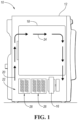
Figure 1 is a schematic side view of a laundry appliance. -
Figure 2 is a perspective view of the laundry appliance. -
Figure 3 is a diagrammatical view of a latch assembly for a laundry appliance according to an embodiment. -
Figure 4 is a diagrammatical view of a latch assembly for a laundry appliance according to another embodiment. -
Figure 5 is a diagrammatical view of a latch assembly and blocker for a laundry appliance according to yet another embodiment. -
Figure 6 is a diagrammatical view of a latch assembly and blocker for a laundry appliance according to a further embodiment. - As required, detailed embodiments of the present invention are disclosed herein; however, it is to be understood that the disclosed embodiments are merely exemplary of the invention that may be embodied in various and alternative forms. The figures are not necessarily to scale; some features may be exaggerated or minimized to show details of particular components. Therefore, specific structural and functional details disclosed herein are not to be interpreted as limiting, but merely as a representative basis for teaching one skilled in the art to variously employ the present invention.
- For purposes of description herein, the terms "upper," "lower," "right," "left," "rear," "front," "vertical," "horizontal," and derivatives thereof shall relate to the disclosure as oriented in
FIG. 1 . Unless stated otherwise, the term "front" shall refer to the surface of the element closer to an intended viewer, and the term "rear" shall refer to the surface of the element further from the intended viewer. However, it is to be understood that the disclosure may assume various alternative orientations, except where expressly specified to the contrary. It is also to be understood that the specific devices and processes illustrated in the attached drawings, and described in the following specification are simply exemplary embodiments of the inventive concepts defined in the appended claims. Hence, specific dimensions and other physical characteristics relating to the embodiments disclosed herein are not to be considered as limiting, unless the claims expressly state otherwise. - Referring to
Figure 1 , alaundry appliance 10 is shown. Thelaundry appliance 10 in the illustrated embodiment is a clothes dryer but may be a washing machine in other embodiments. Thedryer 10 includes acabinet 12 and arotating drum 18. Thedrum 18 is supported for rotational within thecabinet 12. Thedryer 10 may be of the closed-loop type that hasblower 16 circulatingprocess air 20 through arecirculating airflow path 24 that includes thedrum 18. Thedrum 18 and theblower 16 are activated in an operating state and deactivated in an idle state. Theairflow path 24 operates to circulateprocess air 20 from theblower 16 within anair scroll panel 22 and moves theprocess air 20 into thedrum 18. Theprocess air 20 moves through thedrum 18 and circulates within thedrum 18. Theprocess air 20 then moves through a return portion of theairflow path 24 back to theblower 16. Certain filters,heaters 28,heat exchangers 26, and other mechanical devices are incorporated within theairflow path 24 for treating and conditioning theprocess air 20 that is utilized during operation of theappliance 10. - Referring to
Figure 2 , thecabinet 12 includes afront face 30 defining anopening 32 that provides access into thedrum 18. Theopening 32 allows a user to insert wet clothes into thedrum 18 and to subsequently remove dry clothes from thedrum 18 once drying is finished. Theopening 32 is sealed by adoor 34 pivotally attached to thecabinet 12 and movable between a closed position (Figure 1 ) position sealing theopening 32 and an open position (Figure 2 ) spaced from theopening 32. Thedoor 34 may include a seal orgasket 36. Thedoor 34 may be pivotably attached to thecabinet 12 via one or more hinges 38. - A
latch assembly 40 secures thedoor 34 in the closed position when latched. Thelatch assembly 40 may include acatch 42 and astriker 44 that are configured to engage. Thestriker 44 may be mounted on thecabinet 12 and thecatch 42 may be mounted on thedoor 34, or alternatively, thestriker 44 may be mounted on thedoor 34 and thecatch 42 may be mounted on thecabinet 12. Thestriker 44 and thecatch 42 include features for latching or engaging thelatch assembly 40 when they fully connect. Thelatch assembly 40 is further configured to prevent inadvertent latching of thelatch assembly 40 to prevent thedoor 34 from inadvertently sealing or closing access to thedrum 18. For example, thelatch assembly 40 may require additional action by the user to fully close thedoor 34 or latch thestriker 44 to thecatch 42. For example, the user may be required to actuate an actuator when closing thedoor 34 in order to latch thelatch assembly 40. - Different embodiments of the
latch assembly 40 are described below. Each of these embodiments is configured to prevent inadvertent latching. Some of these embodiments accomplish this by misaligning the latch and the catch and others utilize a blocking element to sever the connection path between the latch and the catch or otherwise prevent contact between the striker and the catch. - Referring to
Figure 3 , alatch assembly 50 includes a rotatingstriker 52 and astationary catch 54. In the illustrated embodiment, thestriker 52 arranged on thedoor 34 and thecatch 54 is on thecabinet 12; however, thestriker 52 and thecatch 54 may be switched in other examples. Thestriker 52 may be supported within an interior 56 of the door just under apanel 58 that faces thefront face 30 of thecabinet 12. Thestriker 52 is supported for rotation about an axis that extends in the width (lateral) direction of thedoor 34. - The
striker 52 may include acentral body 60 and a projectingportion 62 configured to engage with thecatch 54. Thestriker 52 includes a retracted position (shown in solid line) and an extended or deployed position (shown in phantom line). Thestriker 52 rotates about the axis to move between the retracted position and the extended position. When thestriker 52 is in the retracted position, thestriker 52 is disposed at least partially within the interior and cannot engage with thecatch 54. (The striker may or may not be completely disposed within the interior 56.) Therefore, thedoor 34 cannot be latched to thecabinet 12. When thestriker 52 is in the extended position, the projectingportion 62 extends past thepanel 58 and is connectable with thecatch 54. Thepanel 58 may define a slot or opening 64 allowing the projectingportion 62 to extend therethrough. - The
striker 52 may be biased to the retracted position by aresilient member 66. Theresilient member 66 may be a spring, such as a torsion spring, clock spring, a coil spring, or the like. In the illustrated embodiment, a torsion spring is shown. Thetorsion spring 66 is configured to urge thestriker 52 to rotate towards the retracted position. - An external force may be required to rotate the
striker 52 from the retracted position to the extended position. Thelatch assembly 50 may include anactuator 70 configured to generate the required external force. Theactuator 70 may include a handle, button, orother element 72 that is operable by a user to actuate thelatch 50 so that thedoor 34 can be fully closed and latched. In the illustrated embodiment, ahandle 72 is shown. Thehandle 72 is operably coupled to thestriker 52 so that actuation of thehandle 72 rotates the projectingportion 62 to the extended position. For example, atension member 76, e.g., a cable, may connect between thehandle 72 and thestriker 52. When a user pulls the handle, a tension force is applied to the cable causing thestriker 52 to rotate against thespring 66. Once this tension force exceeds the force of thespring 66, thestriker 52 rotates to the extended position. The user will may maintain this tension force until thedoor 34 is fully seated with thestriker 52 received within thecatch 54. Once thelatch 50 is fully engaged, the user can release thehandle 72 and thedoor 34 will remain in the closed position. Thedoor 34 may be opened by simply pulling the door open and may not require actuation of thehandle 72. In some embodiments, theactuator 70 may include a mechanism for holding thestriker 52 in the extended position so that the user is not required to hold the handle during the door closure process. Instead, the user may briefly actuate thehandle 72 and the holder mechanism will maintain thestriker 52 in the extended position so that the user is not required to hold thehandle 72 while the door is closed. - While the example of
Figure 3 is shown with the striker being mounted on the door and the catch being mounted on the cabinet, in other embodiments, the striker may be on the cabinet and the catch may be provided on the door. Here, the catch would be the rotating component and the striker would be stationary. Alternatively, the rotating catch or striker may on the cabinet and the stationary component on the door. - Referring to
Figure 4 , alatch assembly 100 includes a slidingstriker 102 and astationary catch 104. In the illustrated embodiment, thestriker 102 is mounted on thedoor 34 and thecatch 104 is mounted on thecabinet 12, but the reverse is also contemplated. Thestriker 102 includes aportion 106 that is disposed within the interior of thedoor 34 and anotherportion 108 that extends outwardly from thedoor 34 to engage with thecatch 104. Thestriker 102 may be configured to move vertically within thedoor 34, which places thestriker 102 into, and out of, alignment with thecatch 104. In this example,striker 102 is misaligned with thecatch 104 when in the lower position (shown in phantom line) and is aligned with thecatch 104 when in the upper position (shown in solid line). Thus, thedoor 34 can only be closed (and thelatch 100 latched) when thestriker 102 is in the upper position. Thestriker 102 is biased towards the lower position to prevent inadvertent latching of thedoor 34. That is, in order to latch thedoor 34, a user must move thestriker 102 to the upper position. In other embodiments, the striker and catch may line in the lower position, in which case the striker may be biased to the upper position. In other embodiments, the moving component, e.g., the striker, may move left-and-right, diagonally, or in the other direction that allows for misalignment and realignment of the latch. - The
striker 102 may be slidably supported by one ormore guide members 110. In one example embodiment, theguide member 110 is a track that is attached thedoor 34. The track may be oriented vertically or any other suitable direction. Thestriker 102 is slidably supported along thetrack 110 allowing thestriker 102 to move up and down between the upper and lower positions. Thedoor 34 may define a slot or opening 112 that is vertically oriented and located adjacent to theguide member 110. Theopening 112 provides clearance for thestriker 102 to move up and down. - The
striker 102 may be biased to the lower position by aresilient member 114. The resilient member may be attached between theportion 106 and ananchor 116 of the door interior. In one example embodiment, theresilient member 114 is a spring, such as a coil spring. - An external force is required to move the
striker 102 from the lower position to the upper position. Thelatch assembly 100 may include anactuator 120 configured to generate the required external force. Theactuator 120 may include a handle, button, orother element 122 that is operably by a user to actuate the latch so that thedoor 34 can be fully closed and latched. In the illustrated embodiment, ahandle 122 is shown. Thehandle 122 is operably coupled to thestriker 102 so that actuation of thehandle 122 slides thestriker 102 to the upper position. For example, atension member 124, e.g., a cable, may connect between thehandle 122 and thestriker 102. When thehandle 122 is pulled, a tension force is applied to thecable 124 urging thestriker 102 to upwardly move against thespring 114. Once this tension force exceeds the force of thespring 114, thestriker 102 will slide to the upper position and into alignment with thecatch 104. The user will maintain this tension until the door is fully seated with thestriker 102 received within thecatch 104. Once thelatch 100 is fully engaged, the user can release thehandle 122 and thedoor 34 will remain in the closed position. Thedoor 34 may be opened by simply pulling the door open and may not require actuation of thehandle 122. In some embodiments, theactuator 120 may include a mechanism for holding thestriker 102 in the upper position so that the user does not have to hold the handle during the door-closing process. Instead, the user may briefly actuate thehandle 122 and the holder mechanism will maintain thestriker 102 in the upper position so that the user is not required to hold thehandle 122 while the door is closed. - While the example of
Figure 4 is shown with the striker being mounted on the door and the catch being mounted on the cabinet, in other embodiments, the striker may be on the cabinet and the catch may be provided on the door. Here, the catch would be the moving element and the striker would be stationary. Alternatively, the moving catch or striker may on the cabinet and the stationary component on the door. - The above-described embodiments of
Figures 3 and 4 utilize movement of the striker or catch to prevent contact and inhibit latching. A different methodology may also be used, wherein a blocking member is used to prevent the striker and catch from connecting. The blocking member may be movable into, and out of, the connection path between the striker and catch. When the blocking member severs the connection path, the striker and catch cannot latch due to the physical barrier therebetween; when the blocking member is out of the connection path, the striker and catch are free to connect when the door is closed. In another example, the blocking member prevents the door from fully closing so that the striker and catch do not connect when the blocking member is deployed. - Referring to
Figure 5 , thedoor 34 may support one of the catch and striker and thecabinet 12 may support the other of the catch and striker, which cooperate to latch when the striker is inserted into the catch. In the illustrated example, thestriker 150 is mounted on thedoor 34 and thecatch 152 is mounted on thecabinet 12. A blockingmember 156 is configured to prevent latching of thedoor 34. The blockingmember 156 may be mounted to the door 34 (as shown) or thecabinet 12. The blockingmember 156 may include a retracted position (shown in solid line) where thedoor 34 can be latched and a blocking position (shown in phantom line) that inhibits thestriker 150 from contacting thecatch 152. - The blocking
member 156 may be supported within an interior 158 of thedoor 34 under apanel 160 that faces thefront face 30 of thecabinet 12. The blockingmember 156 is supported for rotation about an axis that extends in the width (lateral) direction of thedoor 34. The blockingmember 156 may include acentral body 162 and a projectingportion 164, which is the portion that engages with thefront face 30 of thecabinet 12 to prevent latching of thedoor 34. The projectingportion 164 is sized to project farther from thepanel 160 than thestriker 150 so that an air gap is maintained between the tip of thestriker 150 and thecatch 152 if thedoor 34 is closed with the blockingmember 156 in the blocking position. Thepanel 160 may define a slot or opening 170 allowing the projectingportion 164 to extend therethrough. - The blocking
member 156 rotates about the axis to move between the retracted position and the blocking position. When the blockingmember 156 is in the retracted position, the projectingportion 164 is disposed within the interior 158 and cannot inhibit latching. When the blockingmember 156 is in the blocking position, the projectingportion 164 extends past thestriker 150 preventing contact with thecatch 152. The blockingmember 156 may be biased to the blocking position by aresilient member 172. Theresilient member 172 may be a spring, such as a torsion spring, clock spring, a coil spring, or the like. In the illustrated embodiment, a torsion spring is shown. Thetorsion spring 172 is configured to urge the blockingmember 156 to rotate towards the blocking position. - Similar to the example of
Figure 3 , anactuator 180 may be used to rotate the blockingmember 156 from the blocking position to the retracted position. Theactuator 180 may include a handle, button, orother element 182 that is operable by a user to so that the door can be fully closed and latched. In the illustrated embodiment, ahandle 182 is shown. Thehandle 182 is operably coupled to the blockingmember 156 so that actuation of the handle rotates the projectingportion 164 to the retracted position. For example, atension member 184, e.g., a cable, may connect between thehandle 182 and the blockingmember 156. When the handle is pulled, a tension force is applied to thecable 184 causing the blockingmember 156 rotate against thespring 172. Once this tension force exceeds the force of the spring, the blockingmember 156 will rotate to the retracted position. The user will maintain this tension force until the door is fully seated with thestriker 150 received within thecatch 152. Once the latch is fully engaged, the user can release thehandle 182 and thedoor 34 will remain in the closed position. In some embodiments, theactuator 180 may include a mechanism for holding the blockingmember 156 in the retracted position so that the user does not have to hold the handle during the door closure process. Instead, the user may briefly actuate thehandle 182 and the holder mechanism will maintain the blockingmember 156 in the retracted position so that the user is not required to hold thehandle 122 while the door is closed. - Referring to
Figure 6 , a blockingmember 204 may be used to sever theconnection path 206 between thecatch 200 and thestriker 202. The blockingmember 204 may be movable into and out of theconnection path 206. In the illustrated example, the blockingmember 204 is vertically slidable up and down between a blocking position (shown in solid line) in which the blockingmember 208 severs theconnection path 206 and a retracted position (shown in phantom line) in which the blockingmember 204 is outside of theconnection path 206. Alternatively, the blockingmember 208 may slide left and right, or any other direction, to move into and out of theconnection path 206. The blockingmember 204 may be external to the door 34 (as shown) or internal to the door. - The blocking
member 204 is biased to the blocking position by aresilient member 208, such as spring. Example biasing mechanisms are described above and will not be repeated here for brevity. When the blockingmember 204 is in the blocking position, it provides a physical barrier between thecatch 200 and thestriker 202. Any attempt to latch thedoor 34 when the blocking member is in the blocking position will result in thestriker 202 contacting the blockingmember 208 rather than thecatch 200. - An
actuator 210 may be used to move the blockingmember 206 from the blocking position to the retracted position. In the illustrated embodiment, theactuator 210 is configured to slide the blockingmember 204 upwardly and out of the way so that thestriker 202 may be received within thecatch 200 to latch the door. Theactuator 210 may include a handle 212 (or other component as described above) connected to the blockingmember 204 by atension member 214 such as a cable. To close the door, a user may pull the handle to slide the blockingmember 204 out of the way so that the door can be latched closed. A holding member may be included as described above. - The above-described latch assemblies and/or associated blocking members inhibit inadvertent latching of the door to the cabinet. This maintains air supply to the drum when in the idle condition in a closed-loop type dryer.
Claims (15)
- A laundry appliance (10) comprising:a drum (18);a cabinet (12) configured to support the drum (18) for rotation therein, the cabinet (12) including a front face (30) defining an opening (32) that provides access into the drum (18);a door (34) pivotally attached to the cabinet (12) and movable between a closed position and an open position; anda latch assembly (40; 50; 100) configured to secure the door (34) in the closed position, the latch assembly (40; 50; 100) including:a catch (42; 54; 104) supported on one of the door and the front face (30), anda striker (44; 52; 102) supported on the other of the door (34) and the front face (30) and engageable with the catch (42; 54; 104) to latch the latch assembly (40; 50; 100), wherein one of the catch (42; 54; 104) and striker (44; 52; 102) is movable between a first position in which the catch and striker do not engage when the door (34) is in the closed position and a second position in which the catch and striker are configured to engage when the door (34) is in the closed position.
- The laundry appliance (10) of claim 1, wherein the one of the catch (42; 54; 104) and striker (44; 52; 102) is biased to the first position.
- The laundry appliance (10) of claim 1 or 2, wherein the latch assembly (40; 50; 100) further includes an actuator (70; 120) operably coupled to the one of the catch (42; 54; 104) and striker (44; 52; 102) and configured to move the one of the catch and striker from the first position to the second position when actuated by a user.
- The laundry appliance (10) of any one of the preceding claims, wherein the first position is a retracted position, and wherein the second position is an extended position.
- The laundry appliance (10) of any one of the preceding claims, wherein the first position and the second position are vertically or laterally spaced from each other.
- The laundry appliance (10) of any one of the preceding claims, wherein the one of the catch (42; 104) and striker (44; 102) is slidably supported by a guide member (110) and is slidable within the guide member (110) between the first and second positions.
- The laundry appliance (10) of any one of the preceding claims, wherein the latch assembly (40; 50; 100) further includes a resilient member, in particular a spring, (66; 114) biasing the one of the catch (42; 54; 104) and striker (44; 52; 102) to the first position.
- The laundry appliance (10) of any one of the preceding claims, wherein the one of the catch (42; 54; 104) and the striker (44; 52; 102) is the striker (44; 52; 102).
- The laundry appliance (10) of any one of the preceding claims, wherein the one of the catch (42; 54) and the striker (44; 52) moves between the first and second position via rotation about an axis.
- The laundry appliance (10) of any one of the preceding claims, wherein the striker (44; 52) is mounted within an interior of the door (34), and the striker (44; 52) is retracted into the interior when in the first position and projects or partially projects outwardly from the door (34) when in the second position;
optionally wherein the striker (44; 52) includes a central body (60) and a projecting portion (62), wherein, when the striker is in the second position, the projecting portion (62) is configured to engage with the catch (42; 54). - The laundry appliance (10) of any one of the preceding claims, wherein the striker (44; 52) is rotatably mounted and rotates when moving between the first and second positions, the latch assembly (40; 50) further comprising:a/the resilient member (66) urging the striker (44; 52) to rotate towards the first position; andan/the actuator (70) configured to overcome the resilient member (66) and rotate the striker (44; 52) towards the second position when actuated by a user.
- The laundry appliance (10) of any one of the preceding claims when combined with claim 3 or 11, wherein the actuator (70; 120) includes a handle (72; 122) and a tension member (76; 124) connected between the handle (72; 122) and the actuator (70; 120).
- The laundry appliance (10) of any one of the preceding claims 1-8 and 12, wherein the striker (44; 102) includes a portion (106) disposed within the interior of the door (34) and another portion (108) extending outwardly from the door (34) and configured to engage with the catch (104), the striker (44; 102) being configured to move, in particular to vertically move, between the first position, which is a position where the striker is out of alignment with respect to the catch (42; 104), and the second position, which is a position where the striker is in alignment with the catch (42; 104); and
wherein the door (34) can only be closed and the latch assembly (40; 100) latched when the striker (44; 102) is in the second position of alignment with the catch (42; 104). - The laundry appliance (10) of claim 13, wherein the striker (44; 102) is slidably supported along a/the guide member (110) allowing the striker (44; 102) to vertically move up and down between the first and second positions; and wherein the door (34) defines a slot or opening (112) that is vertically oriented and located adjacent to the guide member (110) for providing clearance for the striker (44; 102) to move up and down.
- The laundry appliance (10) of claims 4, 7 and 14, wherein the actuator (120) is operably coupled to the striker (44; 102) and configured to overcome the resilient member and urge the striker (44; 102) to upwardly move towards the second position.
Applications Claiming Priority (1)
| Application Number | Priority Date | Filing Date | Title |
|---|---|---|---|
| US18/175,674 US12492503B2 (en) | 2023-02-28 | 2023-02-28 | Laundry appliance with anti-closure feature |
Publications (1)
| Publication Number | Publication Date |
|---|---|
| EP4424899A1 true EP4424899A1 (en) | 2024-09-04 |
Family
ID=90097703
Family Applications (1)
| Application Number | Title | Priority Date | Filing Date |
|---|---|---|---|
| EP24160078.2A Withdrawn EP4424899A1 (en) | 2023-02-28 | 2024-02-27 | Laundry appliance with anti-closure feature |
Country Status (2)
| Country | Link |
|---|---|
| US (2) | US12492503B2 (en) |
| EP (1) | EP4424899A1 (en) |
Cited By (1)
| Publication number | Priority date | Publication date | Assignee | Title |
|---|---|---|---|---|
| US12492503B2 (en) | 2023-02-28 | 2025-12-09 | Whirlpool Corporation | Laundry appliance with anti-closure feature |
Citations (4)
| Publication number | Priority date | Publication date | Assignee | Title |
|---|---|---|---|---|
| WO2008096222A2 (en) * | 2007-02-05 | 2008-08-14 | Itw Metalflex, Druzba Za Proizvodnjo Delov Za Gospodinjske Aparate, D.O.O. | Blocking device for the door of an electric household appliance, in particular the door of a washing machine |
| US20120032569A1 (en) * | 2010-08-03 | 2012-02-09 | Electrolux Home Products, Inc. | Appliance Door Prop Mechanism |
| US10066334B2 (en) * | 2016-07-08 | 2018-09-04 | Haier Us Appliance Solutions, Inc. | Washing machine appliance with a door lock assembly |
| US10815609B2 (en) * | 2018-07-10 | 2020-10-27 | Haier Us Appliance Solutions, Inc. | Front load washing machine appliance equipped with door reversing locking and latching features |
Family Cites Families (14)
| Publication number | Priority date | Publication date | Assignee | Title |
|---|---|---|---|---|
| US4257173A (en) | 1979-08-27 | 1981-03-24 | Smith Derrick A | No-heat clothes dryer |
| DE10015010C2 (en) * | 2000-03-22 | 2002-08-29 | Eppendorf Ag | Locking a lock with a housing |
| DE10062458B4 (en) * | 2000-12-14 | 2004-06-17 | Whirlpool Corp., Benton Harbor | Locking device for a washing machine or washer-dryer |
| ATE449227T1 (en) * | 2002-02-27 | 2009-12-15 | Emz Hanauer Gmbh & Co Kgaa | UNIT WITH MEMORY METAL ACTUATOR FOR DOOR LOCKS OF HOUSEHOLD APPLIANCES |
| EP2147176B1 (en) * | 2007-05-24 | 2012-08-15 | Illinois Tool Works Inc. | Gasket-compensating latch mechanism |
| EP2336628B9 (en) * | 2009-12-16 | 2013-08-14 | Eppendorf Ag | Lock fastener |
| DE102010039688A1 (en) | 2010-08-24 | 2012-03-01 | BSH Bosch und Siemens Hausgeräte GmbH | Water-bearing household appliance with a ventilated treatment area |
| US10612274B2 (en) | 2012-02-10 | 2020-04-07 | Illinois Tool Works Inc. | Thermally actuated dryer door lock |
| EP3077581B1 (en) * | 2013-12-04 | 2019-01-09 | Illinois Tool Works Inc. | Tamper resistant appliance latch |
| US11319661B1 (en) | 2020-12-22 | 2022-05-03 | Whirlpool Corporation | Ventilation solution for closed-loop dryer systems |
| DE102022127560A1 (en) * | 2021-10-19 | 2023-04-20 | Emz-Hanauer Gmbh & Co. Kgaa | Electrical household appliance and door lock therefor |
| US12378715B2 (en) * | 2021-12-29 | 2025-08-05 | Electrolux Appliances Aktiebolag | Laundry machine door assembly |
| US11976406B2 (en) * | 2021-12-29 | 2024-05-07 | Whirlpool Corporation | Floating inner door of a combination washer/dryer |
| US12492503B2 (en) | 2023-02-28 | 2025-12-09 | Whirlpool Corporation | Laundry appliance with anti-closure feature |
-
2023
- 2023-02-28 US US18/175,674 patent/US12492503B2/en active Active
-
2024
- 2024-02-27 EP EP24160078.2A patent/EP4424899A1/en not_active Withdrawn
-
2025
- 2025-11-14 US US19/389,565 patent/US20260071376A1/en active Pending
Patent Citations (4)
| Publication number | Priority date | Publication date | Assignee | Title |
|---|---|---|---|---|
| WO2008096222A2 (en) * | 2007-02-05 | 2008-08-14 | Itw Metalflex, Druzba Za Proizvodnjo Delov Za Gospodinjske Aparate, D.O.O. | Blocking device for the door of an electric household appliance, in particular the door of a washing machine |
| US20120032569A1 (en) * | 2010-08-03 | 2012-02-09 | Electrolux Home Products, Inc. | Appliance Door Prop Mechanism |
| US10066334B2 (en) * | 2016-07-08 | 2018-09-04 | Haier Us Appliance Solutions, Inc. | Washing machine appliance with a door lock assembly |
| US10815609B2 (en) * | 2018-07-10 | 2020-10-27 | Haier Us Appliance Solutions, Inc. | Front load washing machine appliance equipped with door reversing locking and latching features |
Cited By (1)
| Publication number | Priority date | Publication date | Assignee | Title |
|---|---|---|---|---|
| US12492503B2 (en) | 2023-02-28 | 2025-12-09 | Whirlpool Corporation | Laundry appliance with anti-closure feature |
Also Published As
| Publication number | Publication date |
|---|---|
| US20260071376A1 (en) | 2026-03-12 |
| US20240287729A1 (en) | 2024-08-29 |
| US12492503B2 (en) | 2025-12-09 |
Similar Documents
| Publication | Publication Date | Title |
|---|---|---|
| US20260071376A1 (en) | Laundry appliance with anti-closure feature | |
| CN109252765B (en) | Pull up limit door latch with locking mechanism | |
| RU2506361C2 (en) | Washing machine | |
| EP2141277B1 (en) | Machine for treating textile items, in particular a washing machine | |
| US11781345B2 (en) | Domestic electrical appliance and door latch therefor | |
| US20040104580A1 (en) | Unit having a memory metal actuator for latching devices of household appliances | |
| US6698418B2 (en) | Oven door latch assembly having side mounted motor | |
| US6082787A (en) | Locking and unlocking device of the door of a domestic electrical appliance | |
| CN107550431A (en) | Household electrical appliance, especially dish-washing machine | |
| US20080196453A1 (en) | Laundry machine | |
| EP1304436A2 (en) | A door-lock, particularly for household appliances | |
| US20230119079A1 (en) | Domestic Electrical Appliance and Door Latch Therefor | |
| KR20190113071A (en) | A Cooking Device Having an Automatically Opening Door and an Auto Opening Latch Holder | |
| KR20160097890A (en) | Clothing dryer | |
| EP0965677B1 (en) | A door locking device for an electric household appliance | |
| CN107109758A (en) | The interlock of the closing door of household electrical appliance | |
| US9410349B2 (en) | Appliance latch with improved door retention at elevated temperatures | |
| US3968984A (en) | Door latch | |
| KR102691524B1 (en) | Push-push door latch and domestic electrical appliance equipped therewith | |
| KR101708678B1 (en) | Apparatus for treating laundry | |
| KR20140093448A (en) | Refrigerator | |
| CN114941478A (en) | Door lock for a household appliance and household appliance comprising such a door lock | |
| JP5145183B2 (en) | Door lock device | |
| JPH08266349A (en) | Lock device for cabinet | |
| US11913266B2 (en) | Door assembly for a household appliance |
Legal Events
| Date | Code | Title | Description |
|---|---|---|---|
| PUAI | Public reference made under article 153(3) epc to a published international application that has entered the european phase |
Free format text: ORIGINAL CODE: 0009012 |
|
| STAA | Information on the status of an ep patent application or granted ep patent |
Free format text: STATUS: THE APPLICATION HAS BEEN PUBLISHED |
|
| AK | Designated contracting states |
Kind code of ref document: A1 Designated state(s): AL AT BE BG CH CY CZ DE DK EE ES FI FR GB GR HR HU IE IS IT LI LT LU LV MC ME MK MT NL NO PL PT RO RS SE SI SK SM TR |
|
| STAA | Information on the status of an ep patent application or granted ep patent |
Free format text: STATUS: THE APPLICATION IS DEEMED TO BE WITHDRAWN |
|
| 18D | Application deemed to be withdrawn |
Effective date: 20250305 |