EP4424496A1 - Procédé pour la confection de bandes textiles adhésives - Google Patents
Procédé pour la confection de bandes textiles adhésives Download PDFInfo
- Publication number
- EP4424496A1 EP4424496A1 EP24160746.4A EP24160746A EP4424496A1 EP 4424496 A1 EP4424496 A1 EP 4424496A1 EP 24160746 A EP24160746 A EP 24160746A EP 4424496 A1 EP4424496 A1 EP 4424496A1
- Authority
- EP
- European Patent Office
- Prior art keywords
- adhesive
- adhesive tape
- cutting
- textile
- filaments
- Prior art date
- Legal status (The legal status is an assumption and is not a legal conclusion. Google has not performed a legal analysis and makes no representation as to the accuracy of the status listed.)
- Pending
Links
- 239000000853 adhesive Substances 0.000 title claims abstract description 99
- 230000001070 adhesive effect Effects 0.000 title claims abstract description 97
- 239000004753 textile Substances 0.000 title claims abstract description 64
- 238000004519 manufacturing process Methods 0.000 title claims abstract description 15
- 239000002390 adhesive tape Substances 0.000 claims abstract description 200
- 238000005520 cutting process Methods 0.000 claims abstract description 82
- 239000004744 fabric Substances 0.000 claims abstract description 63
- 238000000034 method Methods 0.000 claims abstract description 59
- 238000007789 sealing Methods 0.000 claims abstract description 56
- 239000000463 material Substances 0.000 claims abstract description 45
- 239000004820 Pressure-sensitive adhesive Substances 0.000 claims abstract description 31
- 239000011248 coating agent Substances 0.000 claims abstract description 31
- 238000000576 coating method Methods 0.000 claims abstract description 31
- 229920002647 polyamide Polymers 0.000 claims abstract description 29
- 239000004952 Polyamide Substances 0.000 claims abstract description 28
- -1 felts Substances 0.000 claims abstract description 25
- 239000005020 polyethylene terephthalate Substances 0.000 claims abstract description 18
- 229920000139 polyethylene terephthalate Polymers 0.000 claims abstract description 18
- 229920000728 polyester Polymers 0.000 claims abstract description 9
- 229920000098 polyolefin Polymers 0.000 claims abstract description 5
- 229920006375 polyphtalamide Polymers 0.000 claims abstract description 5
- 229920000915 polyvinyl chloride Polymers 0.000 claims abstract description 5
- 239000004954 Polyphthalamide Substances 0.000 claims abstract description 4
- 230000008569 process Effects 0.000 claims description 20
- NIXOWILDQLNWCW-UHFFFAOYSA-M Acrylate Chemical compound [O-]C(=O)C=C NIXOWILDQLNWCW-UHFFFAOYSA-M 0.000 claims description 12
- 239000012876 carrier material Substances 0.000 claims description 12
- 229910000831 Steel Inorganic materials 0.000 claims description 11
- 239000010959 steel Substances 0.000 claims description 11
- 229910052782 aluminium Inorganic materials 0.000 claims description 5
- XAGFODPZIPBFFR-UHFFFAOYSA-N aluminium Chemical compound [Al] XAGFODPZIPBFFR-UHFFFAOYSA-N 0.000 claims description 5
- CWYNVVGOOAEACU-UHFFFAOYSA-N Fe2+ Chemical compound [Fe+2] CWYNVVGOOAEACU-UHFFFAOYSA-N 0.000 claims description 4
- 229910052751 metal Inorganic materials 0.000 claims description 4
- 239000002184 metal Substances 0.000 claims description 4
- 229920003051 synthetic elastomer Polymers 0.000 claims description 4
- 239000005061 synthetic rubber Substances 0.000 claims description 4
- 230000002093 peripheral effect Effects 0.000 claims description 3
- 229910000906 Bronze Inorganic materials 0.000 claims description 2
- RYGMFSIKBFXOCR-UHFFFAOYSA-N Copper Chemical compound [Cu] RYGMFSIKBFXOCR-UHFFFAOYSA-N 0.000 claims description 2
- 239000010974 bronze Substances 0.000 claims description 2
- 239000000919 ceramic Substances 0.000 claims description 2
- 239000002131 composite material Substances 0.000 claims description 2
- 229910052802 copper Inorganic materials 0.000 claims description 2
- 239000010949 copper Substances 0.000 claims description 2
- KUNSUQLRTQLHQQ-UHFFFAOYSA-N copper tin Chemical compound [Cu].[Sn] KUNSUQLRTQLHQQ-UHFFFAOYSA-N 0.000 claims description 2
- 229910017083 AlN Inorganic materials 0.000 claims 1
- PIGFYZPCRLYGLF-UHFFFAOYSA-N Aluminum nitride Chemical compound [Al]#N PIGFYZPCRLYGLF-UHFFFAOYSA-N 0.000 claims 1
- 239000004411 aluminium Substances 0.000 claims 1
- 239000000835 fiber Substances 0.000 abstract description 87
- 239000004745 nonwoven fabric Substances 0.000 description 25
- 238000005299 abrasion Methods 0.000 description 22
- 229920005989 resin Polymers 0.000 description 19
- 239000011347 resin Substances 0.000 description 19
- 239000011230 binding agent Substances 0.000 description 15
- 230000033001 locomotion Effects 0.000 description 15
- 229920000642 polymer Polymers 0.000 description 15
- 239000000178 monomer Substances 0.000 description 14
- 239000006185 dispersion Substances 0.000 description 13
- 239000010410 layer Substances 0.000 description 13
- 238000012360 testing method Methods 0.000 description 13
- 230000015572 biosynthetic process Effects 0.000 description 12
- 239000000203 mixture Substances 0.000 description 11
- 238000009958 sewing Methods 0.000 description 11
- 229920001169 thermoplastic Polymers 0.000 description 11
- 239000004416 thermosoftening plastic Substances 0.000 description 10
- NIXOWILDQLNWCW-UHFFFAOYSA-N 2-Propenoic acid Natural products OC(=O)C=C NIXOWILDQLNWCW-UHFFFAOYSA-N 0.000 description 9
- 229920003235 aromatic polyamide Polymers 0.000 description 8
- RSWGJHLUYNHPMX-UHFFFAOYSA-N Abietic-Saeure Natural products C12CCC(C(C)C)=CC2=CCC2C1(C)CCCC2(C)C(O)=O RSWGJHLUYNHPMX-UHFFFAOYSA-N 0.000 description 7
- KHPCPRHQVVSZAH-HUOMCSJISA-N Rosin Natural products O(C/C=C/c1ccccc1)[C@H]1[C@H](O)[C@@H](O)[C@@H](O)[C@@H](CO)O1 KHPCPRHQVVSZAH-HUOMCSJISA-N 0.000 description 7
- 239000004840 adhesive resin Substances 0.000 description 7
- 229920006223 adhesive resin Polymers 0.000 description 7
- CQEYYJKEWSMYFG-UHFFFAOYSA-N butyl acrylate Chemical compound CCCCOC(=O)C=C CQEYYJKEWSMYFG-UHFFFAOYSA-N 0.000 description 7
- 150000001875 compounds Chemical class 0.000 description 7
- 239000004815 dispersion polymer Substances 0.000 description 7
- 239000000047 product Substances 0.000 description 7
- 239000000126 substance Substances 0.000 description 7
- KHPCPRHQVVSZAH-UHFFFAOYSA-N trans-cinnamyl beta-D-glucopyranoside Natural products OC1C(O)C(O)C(CO)OC1OCC=CC1=CC=CC=C1 KHPCPRHQVVSZAH-UHFFFAOYSA-N 0.000 description 7
- LYCAIKOWRPUZTN-UHFFFAOYSA-N Ethylene glycol Chemical compound OCCO LYCAIKOWRPUZTN-UHFFFAOYSA-N 0.000 description 6
- PEDCQBHIVMGVHV-UHFFFAOYSA-N Glycerine Chemical compound OCC(O)CO PEDCQBHIVMGVHV-UHFFFAOYSA-N 0.000 description 6
- 239000003522 acrylic cement Substances 0.000 description 6
- 239000012790 adhesive layer Substances 0.000 description 6
- 239000000969 carrier Substances 0.000 description 6
- 238000011109 contamination Methods 0.000 description 6
- 239000012943 hotmelt Substances 0.000 description 6
- 239000007788 liquid Substances 0.000 description 6
- 238000002844 melting Methods 0.000 description 6
- 230000008018 melting Effects 0.000 description 6
- 238000012545 processing Methods 0.000 description 6
- SMZOUWXMTYCWNB-UHFFFAOYSA-N 2-(2-methoxy-5-methylphenyl)ethanamine Chemical compound COC1=CC=C(C)C=C1CCN SMZOUWXMTYCWNB-UHFFFAOYSA-N 0.000 description 5
- PPBRXRYQALVLMV-UHFFFAOYSA-N Styrene Chemical compound C=CC1=CC=CC=C1 PPBRXRYQALVLMV-UHFFFAOYSA-N 0.000 description 5
- 239000004760 aramid Substances 0.000 description 5
- 150000002148 esters Chemical class 0.000 description 5
- 238000009940 knitting Methods 0.000 description 5
- 230000009467 reduction Effects 0.000 description 5
- 239000002356 single layer Substances 0.000 description 5
- 125000006850 spacer group Chemical group 0.000 description 5
- 235000007586 terpenes Nutrition 0.000 description 5
- 238000004804 winding Methods 0.000 description 5
- GRWFGVWFFZKLTI-IUCAKERBSA-N 1S,5S-(-)-alpha-Pinene Natural products CC1=CC[C@@H]2C(C)(C)[C@H]1C2 GRWFGVWFFZKLTI-IUCAKERBSA-N 0.000 description 4
- GOXQRTZXKQZDDN-UHFFFAOYSA-N 2-Ethylhexyl acrylate Chemical compound CCCCC(CC)COC(=O)C=C GOXQRTZXKQZDDN-UHFFFAOYSA-N 0.000 description 4
- CERQOIWHTDAKMF-UHFFFAOYSA-N Methacrylic acid Chemical compound CC(=C)C(O)=O CERQOIWHTDAKMF-UHFFFAOYSA-N 0.000 description 4
- 125000003118 aryl group Chemical group 0.000 description 4
- 230000008901 benefit Effects 0.000 description 4
- 238000007596 consolidation process Methods 0.000 description 4
- 238000010276 construction Methods 0.000 description 4
- 238000004132 cross linking Methods 0.000 description 4
- 238000001035 drying Methods 0.000 description 4
- 229920001971 elastomer Polymers 0.000 description 4
- 238000010438 heat treatment Methods 0.000 description 4
- 239000000155 melt Substances 0.000 description 4
- 239000005011 phenolic resin Substances 0.000 description 4
- 230000001681 protective effect Effects 0.000 description 4
- 239000007787 solid Substances 0.000 description 4
- 239000002904 solvent Substances 0.000 description 4
- 239000000758 substrate Substances 0.000 description 4
- VZCYOOQTPOCHFL-UHFFFAOYSA-N trans-butenedioic acid Natural products OC(=O)C=CC(O)=O VZCYOOQTPOCHFL-UHFFFAOYSA-N 0.000 description 4
- 238000002604 ultrasonography Methods 0.000 description 4
- XLYOFNOQVPJJNP-UHFFFAOYSA-N water Substances O XLYOFNOQVPJJNP-UHFFFAOYSA-N 0.000 description 4
- VZCYOOQTPOCHFL-OWOJBTEDSA-N Fumaric acid Chemical compound OC(=O)\C=C\C(O)=O VZCYOOQTPOCHFL-OWOJBTEDSA-N 0.000 description 3
- 239000004698 Polyethylene Substances 0.000 description 3
- 239000004743 Polypropylene Substances 0.000 description 3
- WTARULDDTDQWMU-UHFFFAOYSA-N Pseudopinene Natural products C1C2C(C)(C)C1CCC2=C WTARULDDTDQWMU-UHFFFAOYSA-N 0.000 description 3
- YXFVVABEGXRONW-UHFFFAOYSA-N Toluene Chemical compound CC1=CC=CC=C1 YXFVVABEGXRONW-UHFFFAOYSA-N 0.000 description 3
- 239000002253 acid Substances 0.000 description 3
- 150000008065 acid anhydrides Chemical group 0.000 description 3
- XYLMUPLGERFSHI-UHFFFAOYSA-N alpha-Methylstyrene Chemical compound CC(=C)C1=CC=CC=C1 XYLMUPLGERFSHI-UHFFFAOYSA-N 0.000 description 3
- 239000003963 antioxidant agent Substances 0.000 description 3
- 229920001400 block copolymer Polymers 0.000 description 3
- 238000001816 cooling Methods 0.000 description 3
- 229920001577 copolymer Polymers 0.000 description 3
- 238000007872 degassing Methods 0.000 description 3
- 238000013461 design Methods 0.000 description 3
- 230000000694 effects Effects 0.000 description 3
- 239000000806 elastomer Substances 0.000 description 3
- 235000011187 glycerol Nutrition 0.000 description 3
- 229930195733 hydrocarbon Natural products 0.000 description 3
- 150000002430 hydrocarbons Chemical class 0.000 description 3
- WGCNASOHLSPBMP-UHFFFAOYSA-N hydroxyacetaldehyde Natural products OCC=O WGCNASOHLSPBMP-UHFFFAOYSA-N 0.000 description 3
- 238000009434 installation Methods 0.000 description 3
- 229920002521 macromolecule Polymers 0.000 description 3
- 229920001155 polypropylene Polymers 0.000 description 3
- 150000003097 polyterpenes Chemical class 0.000 description 3
- 239000004800 polyvinyl chloride Substances 0.000 description 3
- 230000005855 radiation Effects 0.000 description 3
- 238000007711 solidification Methods 0.000 description 3
- 230000008023 solidification Effects 0.000 description 3
- 150000003505 terpenes Chemical class 0.000 description 3
- 238000012546 transfer Methods 0.000 description 3
- 229920002554 vinyl polymer Polymers 0.000 description 3
- 239000002759 woven fabric Substances 0.000 description 3
- WTARULDDTDQWMU-RKDXNWHRSA-N (+)-β-pinene Chemical compound C1[C@H]2C(C)(C)[C@@H]1CCC2=C WTARULDDTDQWMU-RKDXNWHRSA-N 0.000 description 2
- WTARULDDTDQWMU-IUCAKERBSA-N (-)-Nopinene Natural products C1[C@@H]2C(C)(C)[C@H]1CCC2=C WTARULDDTDQWMU-IUCAKERBSA-N 0.000 description 2
- KPAPHODVWOVUJL-UHFFFAOYSA-N 1-benzofuran;1h-indene Chemical compound C1=CC=C2CC=CC2=C1.C1=CC=C2OC=CC2=C1 KPAPHODVWOVUJL-UHFFFAOYSA-N 0.000 description 2
- JAHNSTQSQJOJLO-UHFFFAOYSA-N 2-(3-fluorophenyl)-1h-imidazole Chemical compound FC1=CC=CC(C=2NC=CN=2)=C1 JAHNSTQSQJOJLO-UHFFFAOYSA-N 0.000 description 2
- 239000013032 Hydrocarbon resin Substances 0.000 description 2
- 229920002292 Nylon 6 Polymers 0.000 description 2
- 229920002367 Polyisobutene Polymers 0.000 description 2
- OFOBLEOULBTSOW-UHFFFAOYSA-N Propanedioic acid Natural products OC(=O)CC(O)=O OFOBLEOULBTSOW-UHFFFAOYSA-N 0.000 description 2
- VYPSYNLAJGMNEJ-UHFFFAOYSA-N Silicium dioxide Chemical compound O=[Si]=O VYPSYNLAJGMNEJ-UHFFFAOYSA-N 0.000 description 2
- XTXRWKRVRITETP-UHFFFAOYSA-N Vinyl acetate Chemical class CC(=O)OC=C XTXRWKRVRITETP-UHFFFAOYSA-N 0.000 description 2
- QYKIQEUNHZKYBP-UHFFFAOYSA-N Vinyl ether Chemical class C=COC=C QYKIQEUNHZKYBP-UHFFFAOYSA-N 0.000 description 2
- RSWGJHLUYNHPMX-ONCXSQPRSA-N abietic acid Chemical compound C([C@@H]12)CC(C(C)C)=CC1=CC[C@@H]1[C@]2(C)CCC[C@@]1(C)C(O)=O RSWGJHLUYNHPMX-ONCXSQPRSA-N 0.000 description 2
- 239000000654 additive Substances 0.000 description 2
- 150000001298 alcohols Chemical class 0.000 description 2
- XCPQUQHBVVXMRQ-UHFFFAOYSA-N alpha-Fenchene Natural products C1CC2C(=C)CC1C2(C)C XCPQUQHBVVXMRQ-UHFFFAOYSA-N 0.000 description 2
- MVNCAPSFBDBCGF-UHFFFAOYSA-N alpha-pinene Natural products CC1=CCC23C1CC2C3(C)C MVNCAPSFBDBCGF-UHFFFAOYSA-N 0.000 description 2
- 230000003712 anti-aging effect Effects 0.000 description 2
- ADCOVFLJGNWWNZ-UHFFFAOYSA-N antimony trioxide Chemical compound O=[Sb]O[Sb]=O ADCOVFLJGNWWNZ-UHFFFAOYSA-N 0.000 description 2
- 239000005000 backing coat Substances 0.000 description 2
- 238000001266 bandaging Methods 0.000 description 2
- ISAOCJYIOMOJEB-UHFFFAOYSA-N benzoin Chemical class C=1C=CC=CC=1C(O)C(=O)C1=CC=CC=C1 ISAOCJYIOMOJEB-UHFFFAOYSA-N 0.000 description 2
- 229930006722 beta-pinene Natural products 0.000 description 2
- VTYYLEPIZMXCLO-UHFFFAOYSA-L calcium carbonate Substances [Ca+2].[O-]C([O-])=O VTYYLEPIZMXCLO-UHFFFAOYSA-L 0.000 description 2
- 230000008859 change Effects 0.000 description 2
- 239000007795 chemical reaction product Substances 0.000 description 2
- 239000003795 chemical substances by application Substances 0.000 description 2
- PMHQVHHXPFUNSP-UHFFFAOYSA-M copper(1+);methylsulfanylmethane;bromide Chemical compound Br[Cu].CSC PMHQVHHXPFUNSP-UHFFFAOYSA-M 0.000 description 2
- 238000013016 damping Methods 0.000 description 2
- 238000011161 development Methods 0.000 description 2
- 230000018109 developmental process Effects 0.000 description 2
- 238000007720 emulsion polymerization reaction Methods 0.000 description 2
- 238000005516 engineering process Methods 0.000 description 2
- 239000004835 fabric adhesive Substances 0.000 description 2
- LCWMKIHBLJLORW-UHFFFAOYSA-N gamma-carene Natural products C1CC(=C)CC2C(C)(C)C21 LCWMKIHBLJLORW-UHFFFAOYSA-N 0.000 description 2
- 229920006270 hydrocarbon resin Polymers 0.000 description 2
- 230000010354 integration Effects 0.000 description 2
- 239000004611 light stabiliser Substances 0.000 description 2
- VZCYOOQTPOCHFL-UPHRSURJSA-N maleic acid Chemical compound OC(=O)\C=C/C(O)=O VZCYOOQTPOCHFL-UPHRSURJSA-N 0.000 description 2
- FPYJFEHAWHCUMM-UHFFFAOYSA-N maleic anhydride Chemical compound O=C1OC(=O)C=C1 FPYJFEHAWHCUMM-UHFFFAOYSA-N 0.000 description 2
- 238000000691 measurement method Methods 0.000 description 2
- LVHBHZANLOWSRM-UHFFFAOYSA-N methylenebutanedioic acid Natural products OC(=O)CC(=C)C(O)=O LVHBHZANLOWSRM-UHFFFAOYSA-N 0.000 description 2
- 229920003052 natural elastomer Polymers 0.000 description 2
- 229920001194 natural rubber Polymers 0.000 description 2
- WXZMFSXDPGVJKK-UHFFFAOYSA-N pentaerythritol Chemical compound OCC(CO)(CO)CO WXZMFSXDPGVJKK-UHFFFAOYSA-N 0.000 description 2
- 239000004014 plasticizer Substances 0.000 description 2
- 229920000058 polyacrylate Polymers 0.000 description 2
- 229920006149 polyester-amide block copolymer Polymers 0.000 description 2
- 229920000573 polyethylene Polymers 0.000 description 2
- 230000009993 protective function Effects 0.000 description 2
- 238000004080 punching Methods 0.000 description 2
- GRWFGVWFFZKLTI-UHFFFAOYSA-N rac-alpha-Pinene Natural products CC1=CCC2C(C)(C)C1C2 GRWFGVWFFZKLTI-UHFFFAOYSA-N 0.000 description 2
- 239000002994 raw material Substances 0.000 description 2
- 229920006395 saturated elastomer Polymers 0.000 description 2
- 230000035882 stress Effects 0.000 description 2
- 238000010998 test method Methods 0.000 description 2
- 125000000391 vinyl group Chemical group [H]C([*])=C([H])[H] 0.000 description 2
- MSMAPCFQRXQMRL-UHFFFAOYSA-N (2-oxo-1,2-diphenylethyl) prop-2-enoate Chemical compound C=1C=CC=CC=1C(OC(=O)C=C)C(=O)C1=CC=CC=C1 MSMAPCFQRXQMRL-UHFFFAOYSA-N 0.000 description 1
- NEFZIZUSNPOFFC-UHFFFAOYSA-N 2-hydroxy-1,2-diphenylethanone;2-methylprop-2-enoic acid Chemical compound CC(=C)C(O)=O.C=1C=CC=CC=1C(O)C(=O)C1=CC=CC=C1 NEFZIZUSNPOFFC-UHFFFAOYSA-N 0.000 description 1
- QISOBCMNUJQOJU-UHFFFAOYSA-N 4-bromo-1h-pyrazole-5-carboxylic acid Chemical compound OC(=O)C=1NN=CC=1Br QISOBCMNUJQOJU-UHFFFAOYSA-N 0.000 description 1
- 229920005789 ACRONAL® acrylic binder Polymers 0.000 description 1
- QTBSBXVTEAMEQO-UHFFFAOYSA-M Acetate Chemical compound CC([O-])=O QTBSBXVTEAMEQO-UHFFFAOYSA-M 0.000 description 1
- 244000198134 Agave sisalana Species 0.000 description 1
- PNEYBMLMFCGWSK-UHFFFAOYSA-N Alumina Chemical class [O-2].[O-2].[O-2].[Al+3].[Al+3] PNEYBMLMFCGWSK-UHFFFAOYSA-N 0.000 description 1
- 239000004114 Ammonium polyphosphate Substances 0.000 description 1
- 244000025254 Cannabis sativa Species 0.000 description 1
- 235000012766 Cannabis sativa ssp. sativa var. sativa Nutrition 0.000 description 1
- 235000012765 Cannabis sativa ssp. sativa var. spontanea Nutrition 0.000 description 1
- 229920000049 Carbon (fiber) Polymers 0.000 description 1
- 244000060011 Cocos nucifera Species 0.000 description 1
- 235000013162 Cocos nucifera Nutrition 0.000 description 1
- 229920000742 Cotton Polymers 0.000 description 1
- 229920000089 Cyclic olefin copolymer Polymers 0.000 description 1
- 229920002943 EPDM rubber Polymers 0.000 description 1
- 241000196324 Embryophyta Species 0.000 description 1
- 239000004908 Emulsion polymer Substances 0.000 description 1
- 229920000181 Ethylene propylene rubber Polymers 0.000 description 1
- 241000219146 Gossypium Species 0.000 description 1
- 240000006240 Linum usitatissimum Species 0.000 description 1
- 235000004431 Linum usitatissimum Nutrition 0.000 description 1
- 229920000433 Lyocell Polymers 0.000 description 1
- 229920000877 Melamine resin Polymers 0.000 description 1
- 239000004640 Melamine resin Substances 0.000 description 1
- 239000006057 Non-nutritive feed additive Substances 0.000 description 1
- ISWSIDIOOBJBQZ-UHFFFAOYSA-N Phenol Chemical compound OC1=CC=CC=C1 ISWSIDIOOBJBQZ-UHFFFAOYSA-N 0.000 description 1
- OAICVXFJPJFONN-UHFFFAOYSA-N Phosphorus Chemical compound [P] OAICVXFJPJFONN-UHFFFAOYSA-N 0.000 description 1
- 108010064851 Plant Proteins Proteins 0.000 description 1
- 239000005062 Polybutadiene Substances 0.000 description 1
- 229920002873 Polyethylenimine Polymers 0.000 description 1
- 229920000297 Rayon Polymers 0.000 description 1
- 239000002174 Styrene-butadiene Substances 0.000 description 1
- XSQUKJJJFZCRTK-UHFFFAOYSA-N Urea Natural products NC(N)=O XSQUKJJJFZCRTK-UHFFFAOYSA-N 0.000 description 1
- 239000006096 absorbing agent Substances 0.000 description 1
- 229920005700 acResin® Polymers 0.000 description 1
- 229920005703 acResin® A 260 UV Polymers 0.000 description 1
- 230000001133 acceleration Effects 0.000 description 1
- 150000003926 acrylamides Chemical class 0.000 description 1
- 150000001252 acrylic acid derivatives Chemical class 0.000 description 1
- 230000004913 activation Effects 0.000 description 1
- 238000004026 adhesive bonding Methods 0.000 description 1
- 230000032683 aging Effects 0.000 description 1
- 150000001412 amines Chemical class 0.000 description 1
- 235000019826 ammonium polyphosphate Nutrition 0.000 description 1
- 229920001276 ammonium polyphosphate Polymers 0.000 description 1
- 238000004873 anchoring Methods 0.000 description 1
- 235000021120 animal protein Nutrition 0.000 description 1
- 125000000129 anionic group Chemical group 0.000 description 1
- QVGXLLKOCUKJST-UHFFFAOYSA-N atomic oxygen Chemical compound [O] QVGXLLKOCUKJST-UHFFFAOYSA-N 0.000 description 1
- 238000010923 batch production Methods 0.000 description 1
- 238000005452 bending Methods 0.000 description 1
- 238000009835 boiling Methods 0.000 description 1
- MTAZNLWOLGHBHU-UHFFFAOYSA-N butadiene-styrene rubber Chemical compound C=CC=C.C=CC1=CC=CC=C1 MTAZNLWOLGHBHU-UHFFFAOYSA-N 0.000 description 1
- 229920005549 butyl rubber Polymers 0.000 description 1
- 235000010216 calcium carbonate Nutrition 0.000 description 1
- 238000003490 calendering Methods 0.000 description 1
- 235000009120 camo Nutrition 0.000 description 1
- 239000004202 carbamide Substances 0.000 description 1
- 235000013877 carbamide Nutrition 0.000 description 1
- 125000004432 carbon atom Chemical group C* 0.000 description 1
- 239000006229 carbon black Substances 0.000 description 1
- 235000019241 carbon black Nutrition 0.000 description 1
- 239000004917 carbon fiber Substances 0.000 description 1
- 125000002091 cationic group Chemical group 0.000 description 1
- 235000005607 chanvre indien Nutrition 0.000 description 1
- 238000001311 chemical methods and process Methods 0.000 description 1
- 238000005056 compaction Methods 0.000 description 1
- 238000010924 continuous production Methods 0.000 description 1
- 238000006073 displacement reaction Methods 0.000 description 1
- 239000000975 dye Substances 0.000 description 1
- 238000010894 electron beam technology Methods 0.000 description 1
- 239000000945 filler Substances 0.000 description 1
- 239000012467 final product Substances 0.000 description 1
- 239000003063 flame retardant Substances 0.000 description 1
- 230000009969 flowable effect Effects 0.000 description 1
- 238000009472 formulation Methods 0.000 description 1
- 239000001530 fumaric acid Substances 0.000 description 1
- 230000006870 function Effects 0.000 description 1
- 230000004927 fusion Effects 0.000 description 1
- 239000011521 glass Substances 0.000 description 1
- 229910052736 halogen Inorganic materials 0.000 description 1
- 150000002367 halogens Chemical class 0.000 description 1
- 239000011487 hemp Substances 0.000 description 1
- 229920001903 high density polyethylene Polymers 0.000 description 1
- 238000005984 hydrogenation reaction Methods 0.000 description 1
- 150000002432 hydroperoxides Chemical class 0.000 description 1
- 230000006872 improvement Effects 0.000 description 1
- 229910052500 inorganic mineral Inorganic materials 0.000 description 1
- 150000002576 ketones Chemical class 0.000 description 1
- 238000002372 labelling Methods 0.000 description 1
- 238000003475 lamination Methods 0.000 description 1
- 239000002346 layers by function Substances 0.000 description 1
- 229920001684 low density polyethylene Polymers 0.000 description 1
- 239000011976 maleic acid Substances 0.000 description 1
- 238000005259 measurement Methods 0.000 description 1
- 239000006078 metal deactivator Substances 0.000 description 1
- 125000005397 methacrylic acid ester group Chemical group 0.000 description 1
- 239000011707 mineral Substances 0.000 description 1
- 235000010755 mineral Nutrition 0.000 description 1
- 229920005615 natural polymer Polymers 0.000 description 1
- IULGYNXPKZHCIA-UHFFFAOYSA-N octadecyl carbamate Chemical compound CCCCCCCCCCCCCCCCCCOC(N)=O IULGYNXPKZHCIA-UHFFFAOYSA-N 0.000 description 1
- 239000003921 oil Substances 0.000 description 1
- 230000003287 optical effect Effects 0.000 description 1
- 239000003960 organic solvent Substances 0.000 description 1
- 229910052760 oxygen Inorganic materials 0.000 description 1
- 239000001301 oxygen Substances 0.000 description 1
- SOQBVABWOPYFQZ-UHFFFAOYSA-N oxygen(2-);titanium(4+) Chemical class [O-2].[O-2].[Ti+4] SOQBVABWOPYFQZ-UHFFFAOYSA-N 0.000 description 1
- 239000000123 paper Substances 0.000 description 1
- 235000011837 pasties Nutrition 0.000 description 1
- 230000035515 penetration Effects 0.000 description 1
- 239000000049 pigment Substances 0.000 description 1
- 235000021118 plant-derived protein Nutrition 0.000 description 1
- 229920003023 plastic Polymers 0.000 description 1
- 239000004033 plastic Substances 0.000 description 1
- 229920002857 polybutadiene Polymers 0.000 description 1
- 229920001195 polyisoprene Polymers 0.000 description 1
- 229920005594 polymer fiber Polymers 0.000 description 1
- 239000002952 polymeric resin Substances 0.000 description 1
- 238000006116 polymerization reaction Methods 0.000 description 1
- 229920001296 polysiloxane Polymers 0.000 description 1
- 229920002635 polyurethane Polymers 0.000 description 1
- 239000004814 polyurethane Substances 0.000 description 1
- 230000008092 positive effect Effects 0.000 description 1
- 239000000843 powder Substances 0.000 description 1
- 238000007639 printing Methods 0.000 description 1
- 238000004886 process control Methods 0.000 description 1
- 238000003672 processing method Methods 0.000 description 1
- 238000003847 radiation curing Methods 0.000 description 1
- 230000003014 reinforcing effect Effects 0.000 description 1
- 239000013557 residual solvent Substances 0.000 description 1
- 238000005096 rolling process Methods 0.000 description 1
- 239000005060 rubber Substances 0.000 description 1
- 229920006012 semi-aromatic polyamide Polymers 0.000 description 1
- 150000004760 silicates Chemical class 0.000 description 1
- 239000000377 silicon dioxide Substances 0.000 description 1
- 235000012239 silicon dioxide Nutrition 0.000 description 1
- 239000013464 silicone adhesive Substances 0.000 description 1
- 239000007921 spray Substances 0.000 description 1
- 239000007858 starting material Substances 0.000 description 1
- 238000003860 storage Methods 0.000 description 1
- 238000005728 strengthening Methods 0.000 description 1
- 229920006132 styrene block copolymer Polymers 0.000 description 1
- 239000011115 styrene butadiene Substances 0.000 description 1
- 229920003048 styrene butadiene rubber Polymers 0.000 description 1
- 230000008961 swelling Effects 0.000 description 1
- 230000002195 synergetic effect Effects 0.000 description 1
- 229920003002 synthetic resin Polymers 0.000 description 1
- 230000008646 thermal stress Effects 0.000 description 1
- 239000012815 thermoplastic material Substances 0.000 description 1
- 229920001187 thermosetting polymer Polymers 0.000 description 1
- 235000010215 titanium dioxide Nutrition 0.000 description 1
- GWEVSGVZZGPLCZ-UHFFFAOYSA-N titanium dioxide Inorganic materials O=[Ti]=O GWEVSGVZZGPLCZ-UHFFFAOYSA-N 0.000 description 1
- ILJSQTXMGCGYMG-UHFFFAOYSA-N triacetic acid Chemical compound CC(=O)CC(=O)CC(O)=O ILJSQTXMGCGYMG-UHFFFAOYSA-N 0.000 description 1
- 230000001960 triggered effect Effects 0.000 description 1
- 229920001567 vinyl ester resin Polymers 0.000 description 1
- 230000003313 weakening effect Effects 0.000 description 1
- 238000009736 wetting Methods 0.000 description 1
- 210000002268 wool Anatomy 0.000 description 1
- 235000014692 zinc oxide Nutrition 0.000 description 1
- RNWHGQJWIACOKP-UHFFFAOYSA-N zinc;oxygen(2-) Chemical class [O-2].[Zn+2] RNWHGQJWIACOKP-UHFFFAOYSA-N 0.000 description 1
- 239000004711 α-olefin Substances 0.000 description 1
Images


Classifications
-
- C—CHEMISTRY; METALLURGY
- C09—DYES; PAINTS; POLISHES; NATURAL RESINS; ADHESIVES; COMPOSITIONS NOT OTHERWISE PROVIDED FOR; APPLICATIONS OF MATERIALS NOT OTHERWISE PROVIDED FOR
- C09J—ADHESIVES; NON-MECHANICAL ASPECTS OF ADHESIVE PROCESSES IN GENERAL; ADHESIVE PROCESSES NOT PROVIDED FOR ELSEWHERE; USE OF MATERIALS AS ADHESIVES
- C09J7/00—Adhesives in the form of films or foils
- C09J7/20—Adhesives in the form of films or foils characterised by their carriers
- C09J7/21—Paper; Textile fabrics
-
- B—PERFORMING OPERATIONS; TRANSPORTING
- B29—WORKING OF PLASTICS; WORKING OF SUBSTANCES IN A PLASTIC STATE IN GENERAL
- B29C—SHAPING OR JOINING OF PLASTICS; SHAPING OF MATERIAL IN A PLASTIC STATE, NOT OTHERWISE PROVIDED FOR; AFTER-TREATMENT OF THE SHAPED PRODUCTS, e.g. REPAIRING
- B29C66/00—General aspects of processes or apparatus for joining preformed parts
- B29C66/70—General aspects of processes or apparatus for joining preformed parts characterised by the composition, physical properties or the structure of the material of the parts to be joined; Joining with non-plastics material
- B29C66/71—General aspects of processes or apparatus for joining preformed parts characterised by the composition, physical properties or the structure of the material of the parts to be joined; Joining with non-plastics material characterised by the composition of the plastics material of the parts to be joined
-
- C—CHEMISTRY; METALLURGY
- C09—DYES; PAINTS; POLISHES; NATURAL RESINS; ADHESIVES; COMPOSITIONS NOT OTHERWISE PROVIDED FOR; APPLICATIONS OF MATERIALS NOT OTHERWISE PROVIDED FOR
- C09J—ADHESIVES; NON-MECHANICAL ASPECTS OF ADHESIVE PROCESSES IN GENERAL; ADHESIVE PROCESSES NOT PROVIDED FOR ELSEWHERE; USE OF MATERIALS AS ADHESIVES
- C09J7/00—Adhesives in the form of films or foils
- C09J7/30—Adhesives in the form of films or foils characterised by the adhesive composition
- C09J7/38—Pressure-sensitive adhesives [PSA]
-
- B—PERFORMING OPERATIONS; TRANSPORTING
- B65—CONVEYING; PACKING; STORING; HANDLING THIN OR FILAMENTARY MATERIAL
- B65H—HANDLING THIN OR FILAMENTARY MATERIAL, e.g. SHEETS, WEBS, CABLES
- B65H2301/00—Handling processes for sheets or webs
- B65H2301/40—Type of handling process
- B65H2301/41—Winding, unwinding
- B65H2301/414—Winding
- B65H2301/4148—Winding slitting
-
- C—CHEMISTRY; METALLURGY
- C09—DYES; PAINTS; POLISHES; NATURAL RESINS; ADHESIVES; COMPOSITIONS NOT OTHERWISE PROVIDED FOR; APPLICATIONS OF MATERIALS NOT OTHERWISE PROVIDED FOR
- C09J—ADHESIVES; NON-MECHANICAL ASPECTS OF ADHESIVE PROCESSES IN GENERAL; ADHESIVE PROCESSES NOT PROVIDED FOR ELSEWHERE; USE OF MATERIALS AS ADHESIVES
- C09J2203/00—Applications of adhesives in processes or use of adhesives in the form of films or foils
- C09J2203/302—Applications of adhesives in processes or use of adhesives in the form of films or foils for bundling cables
-
- C—CHEMISTRY; METALLURGY
- C09—DYES; PAINTS; POLISHES; NATURAL RESINS; ADHESIVES; COMPOSITIONS NOT OTHERWISE PROVIDED FOR; APPLICATIONS OF MATERIALS NOT OTHERWISE PROVIDED FOR
- C09J—ADHESIVES; NON-MECHANICAL ASPECTS OF ADHESIVE PROCESSES IN GENERAL; ADHESIVE PROCESSES NOT PROVIDED FOR ELSEWHERE; USE OF MATERIALS AS ADHESIVES
- C09J2400/00—Presence of inorganic and organic materials
- C09J2400/20—Presence of organic materials
- C09J2400/26—Presence of textile or fabric
- C09J2400/263—Presence of textile or fabric in the substrate
-
- C—CHEMISTRY; METALLURGY
- C09—DYES; PAINTS; POLISHES; NATURAL RESINS; ADHESIVES; COMPOSITIONS NOT OTHERWISE PROVIDED FOR; APPLICATIONS OF MATERIALS NOT OTHERWISE PROVIDED FOR
- C09J—ADHESIVES; NON-MECHANICAL ASPECTS OF ADHESIVE PROCESSES IN GENERAL; ADHESIVE PROCESSES NOT PROVIDED FOR ELSEWHERE; USE OF MATERIALS AS ADHESIVES
- C09J2423/00—Presence of polyolefin
- C09J2423/006—Presence of polyolefin in the substrate
-
- C—CHEMISTRY; METALLURGY
- C09—DYES; PAINTS; POLISHES; NATURAL RESINS; ADHESIVES; COMPOSITIONS NOT OTHERWISE PROVIDED FOR; APPLICATIONS OF MATERIALS NOT OTHERWISE PROVIDED FOR
- C09J—ADHESIVES; NON-MECHANICAL ASPECTS OF ADHESIVE PROCESSES IN GENERAL; ADHESIVE PROCESSES NOT PROVIDED FOR ELSEWHERE; USE OF MATERIALS AS ADHESIVES
- C09J2433/00—Presence of (meth)acrylic polymer
-
- C—CHEMISTRY; METALLURGY
- C09—DYES; PAINTS; POLISHES; NATURAL RESINS; ADHESIVES; COMPOSITIONS NOT OTHERWISE PROVIDED FOR; APPLICATIONS OF MATERIALS NOT OTHERWISE PROVIDED FOR
- C09J—ADHESIVES; NON-MECHANICAL ASPECTS OF ADHESIVE PROCESSES IN GENERAL; ADHESIVE PROCESSES NOT PROVIDED FOR ELSEWHERE; USE OF MATERIALS AS ADHESIVES
- C09J2467/00—Presence of polyester
- C09J2467/006—Presence of polyester in the substrate
Definitions
- the invention describes a method for manufacturing textile adhesive tapes, in particular adhesive tapes for wrapping cables, whereby a plurality of strip-shaped adhesive tapes, each with two cutting edges on the edge, are produced from an adhesive tape web comprising a textile material to which an adhesive coating, preferably a pressure-sensitive adhesive, is applied on at least one side by cutting the adhesive tape web in the pulling direction.
- the adhesive tapes produced according to this method are particularly suitable for wrapping elongated items such as cable harnesses in automobiles.
- Adhesive tapes have been used in industry for some time to produce cable harnesses.
- the adhesive tapes are used to bundle a large number of electrical cables before installation or when already assembled, for example to reduce the space required by the cable bundle by bandaging and to achieve additional protective functions such as protection against mechanical and/or thermal stress.
- Adhesive tapes for wrapping elongated goods are, for example, EP 1 848 006 A2 , the EN 10 2013 213 726 A1 and the EP 2 497 805 A1 known.
- a carrier web for example a textile carrier web
- a mostly self-adhesive coating on one or both sides in an appropriate coating system.
- the adhesive tapes are applied to a cover material (also known as a release material) before winding, which is then wound up together with the adhesive tape.
- cover materials are known to those skilled in the art as release liners or liners.
- a liner (release paper, release film) is not part of an adhesive tape, but only an aid for its production, storage or further processing by punching. In addition, unlike an adhesive tape carrier, a liner is not firmly connected to an adhesive layer.
- the carrier material equipped with adhesive mass called adhesive tape web
- adhesive tape web is wound up together with the liner into a so-called jumbo roll or mother roll in the form of an Archimedean spiral.
- this master roll is unwound again, whereby several strip-shaped adhesive tapes of the desired width are produced from the master roll by cutting in the pull-off direction of the master roll, which in turn are usually wound onto cores made of cardboard or plastic, for example, to form individual adhesive tape rolls, also in the form of an Archimedean spiral.
- the resulting adhesive tape rolls which are narrow compared to the width of the parent roll, are called plate rolls.
- Cutting can also be done directly after production, i.e. without the adhesive tape strip and liner being wound up and unwound again.
- adhesive tapes are produced by cutting adhesive tape rolls directly from a jumbo or master roll.
- Standard widths for these disc rolls are 9, 19, 25, 38 or 50 mm with a standard length (running length) of 10, 15, 25 or 50 m.
- Different cutting methods are known for cutting the adhesive tape rolls: roll cutting with a razor blade cut, where a fixed knife is used, roll cutting with a crushing knife (round knife) on a counter shaft provided for this purpose, roll cutting with a zigzag cut and cutting in a scissor cut (S-cut) with two counter-rotating round knives lying next to each other.
- FIG. 4 Microscopically magnified images of the side edge of a fabric adhesive tape that has been cut using a razor blade are shown.
- the warp and weft threads of the fabric are made up of individual filaments.
- the filaments fray at the cutting edge due to damage to the warp and especially the weft threads.
- the filaments protrude clearly, which results in a visually very unclean cutting edge.
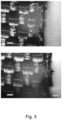
- the Figure 5 shows microscopically enlarged images of the side edge of the same fabric adhesive tape that has been sealed by the process according to the invention.
- Ultrasonic cutting leads to an improvement in the cutting edges because the textile materials are partially sealed at their edges, so that less fraying and less lint formation can be observed at the cutting edges.
- FIG 6 shows in direct comparison the fabric tape that has only been cut and not sealed ( Figure 6a )), which uses ultrasonic cutting according to the WO 2016/128268 A1 has been cut ( Figure 6b )) and which has been sealed by the method according to the invention ( Figure 6c )).
- the cut edge sealed by the method according to the invention is completely lint-free and there are no fraying marks.
- the ultrasonically cut fabric shows (contrary to the WO 2016/128268 A1 discussed results) there is some lint and a few frayings.
- WO 2016/128268 A1 suggests additional cooling of the adhesive layer as a countermeasure. For this reason, in practice - as in the WO 2016/128268 A1 stated - with this ultrasonic cutting process only low web speeds of 25 m/min can be achieved.
- Carrier tape material is fed from an unwinding roll in the longitudinal direction and then cut into longitudinal strips, after which the longitudinal strips are further fanned out into at least two longitudinal strip webs which are spaced apart from one another predominantly vertically to the longitudinal direction, and after which the two longitudinal strip webs are finally cut to length and wound up as an adhesive tape roll on at least one associated take-up roll.
- An ultrasonic cutting device is also mentioned as a cutting device or longitudinal cutting device.
- the present invention is therefore based on the object of avoiding the above disadvantages and providing a method with which adhesive tapes with a smooth cut edge can be produced without fraying, thread formation or lint formation.
- the present invention is based on the object of providing an adhesive tape which has smooth cut edges so that there is no thread formation or lint formation at the edges.
- the invention is based on the object of being able to increase the production speed in a significant sense in order to ensure a more efficient use of resources.
- the invention also relates to an adhesive tape which is produced according to the method according to the invention, wherein this adhesive tape comprises a strip-shaped textile carrier and preferably a one-sided adhesive coating as well as two cut edges at the edges where the textile carrier material is fused so that it is free of lint and threads. Furthermore, special uses of the adhesive tapes produced according to the invention are within the scope of the inventive concept.
- the invention relates to a method for manufacturing textile adhesive tapes, in particular adhesive tapes for wrapping cables, wherein a plurality of strip-shaped adhesive tapes, each with two cutting edges on the edge, are produced from an adhesive tape web comprising a textile material selected from the group of scrims, braids, needle-punched textiles, felts, fabrics or fleeces and to which an adhesive coating, preferably pressure-sensitive adhesive, is applied on at least one side by cutting in the pull-off direction of the adhesive tape web.
- an adhesive coating preferably pressure-sensitive adhesive
- At least one of the cut edges of the adhesive tapes is thermally heated after cutting by means of a sealing tool to such an extent that the fibres and/or filaments forming the textile are at least partially melted, so that connection points are formed between the fibres and/or filaments, wherein the material used to form the fibres and/or filaments consists of at least 50% by weight of polyester such as PET or PBT, preferably polyethylene terephthalate, of polyamide such as non-aromatic polyamide such as Polyamide 6, polyamide 6.6, polyamide 4.6, polyolefin such as polyethylene or polypropylene, polyphthalamide or PVC.
- Connection points form between two or more fibers and/or filaments when they bond and stick together by heating in the melting range of the polymer. After subsequent cooling, these connections are restricted in their mobility.
- both cut edges of the adhesive tapes are thermally heated after cutting by means of a sealing tool to such an extent that the fibers and/or filaments forming the textile are at least partially melted, so that connection points are formed between the fibers and/or filaments.
- the sealing tool comprises a rail, in particular one that can be heated electrically, which is in contact with one of the two cutting edges.
- This rail is selected so that it has appropriate thermal and mechanical properties (abrasion resistance).
- the preferred material for the rail is ceramic (e.g. aluminum nitride), a composite material (e.g. made of highly thermally conductive carbon fibers), ferrous or non-ferrous metal (e.g. steel, aluminum, bronze, copper).
- ceramic e.g. aluminum nitride
- composite material e.g. made of highly thermally conductive carbon fibers
- ferrous or non-ferrous metal e.g. steel, aluminum, bronze, copper.
- the sealing tool comprises two heatable rails which are in contact with both cutting edges.
- the adhesive tapes are preferably guided with both cut edges past the heated, i.e. hot, rails.
- the rails have a temperature that is above the melting point of the material that is to form the fibers and/or filaments and is to be melted. This temperature is preferably between 250 °C and 450 °C, preferably 350 °C and 400 °C.
- the speed at which the adhesive tapes are fed through the sealing tool also depends on the length of the contact area between the rail and the cutting edge. Speeds of 0.6 to 1.7 m/s with a contact area length of 6 to 14 cm have proven to be suitable. 350 °C at a speed of 1.3 m/s and a contact area of 9 cm are optimal.
- the carrier material is melted by the introduced energy so that the individual fibers and/or filaments melt together and seal at certain points.
- Higher energy input and sliding past the heated element can also melt the entire cutting edge. Almost all fibers and/or filaments that touch the heating element are heated to the melting point.
- the soft fibers and/or filaments slide past the heating elements at the speed of the web and a largely uniform polymer surface can form, where the individual fibers and/or filaments are difficult to recognize in their original form.
- the level of energy input to the carrier material has a significant influence on the sealing quality. Too little energy input leads to insufficient sealing, while too much energy input causes the material to undergo excessive thermal changes and thus negatively affects the quality.
- the method according to the invention has the very great advantage that a constant energy input to the cutting edges can be ensured by appropriate coordination of the factors influencing the sealing.
- the temperature control of the sealing tool can be designed in such a way that the energy input is as constant as possible during the sealing process and when the material web is at a standstill. For example, if the contact area between the cutting edge and the sealing tool remains the same, the temperature of the sealing tool can be increased as the web speed increases. Conversely, the temperature can be reduced when the belt speed is reduced.
- the contact area between the cutting edge and the sealing tool can be increased to ensure a constant energy input during the acceleration of the material web, i.e. the contact area between the sealing tool and the material web is variably adapted to the current material web speed.
- the sealing tool can be swiveled in using a rotary movement and/or moved linearly so that the contact area between the rail and the cutting edge is increased.
- a combination of both types of movement is also possible.
- the Figure 7 shows the different relative movements between the material web and the sealing tool.
- the rails can have a different geometry, for example a rectangular shape, a circular shape or a triangular shape. If the rails are pivoted in a rotational manner, a contact surface is created that is adapted to the track speed, depending on the relative position of the rails to the cutting edges.
- Figure 10 represents the combination of a linear and a rotational movement. It is easy to see that, depending on the design of the rail, a very high level of flexibility is achieved with regard to the contact surfaces between the material web and the rail.
- a rotary movement is easy to integrate, but requires more space in the area of the track guide.
- the volume of the sealing tool increases.
- a linear movement requires less space than a rotary movement, but the integration is more complex.
- the combination of both forms of movement brings the highest level of complexity for integration, with little space required and the smallest volume for the sealing tool.
- the contact time during which the material web is in contact with the sealing tool changes, which leads to a change in the energy input.
- the temperature of the sealing tool and the contact surface can be coordinated by a relative movement between the sealing tool and the material web so that a constant energy input can be achieved.
- the sealing tool has two parallel rails, the distance between which is less than the width of the adhesive tape, preferably the difference is between 1 and 4 mm.
- the distance between the two rails is less than the width of the adhesive tape, so that the adhesive tape is in the form of a bow, similar to a
- gutter is bent. Due to the flexural rigidity of the carrier material, the edges of the adhesive tape are simultaneously pressed against the rails of the sealing tool with constant pressure in both directions, so that energy can be transferred from the rail to the cutting edge.
- the adhesive tape is also preferable for the adhesive tape to be guided through the sealing tool in such a way that, in the case of adhesive tapes coated on one side, the textile carrier forms the outer arch and the adhesive mass forms the inner arch. This ensures that the adhesive mass has no or only very little contact with the rails.
- the sealing tool consists of two rails 31, 41, shown looking in the direction of travel of the adhesive tape. Since the distance between the two rails 31, 41 is smaller than the width of the adhesive tape, the adhesive tape forms an arc when it passes through the sealing tool. In the arc, the adhesive layer 2 forms the inner arc, while the textile carrier 1 forms the outer arc. In this way, only the textile carrier 1 touches the rails 31, 41.
- the rails 31, 41 each have a support 32, 42 at their base extending in the direction of the other rail 31, 41.
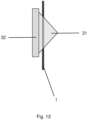
- the Figure 12 shows the sealing tool consisting of two rails 31, 41 with a view of the cutting edge of the adhesive tape.
- the rails 31, 41 have a triangular base area according to a preferred embodiment of the invention.
- the height h of the bend becomes larger and the central angle ⁇ becomes smaller the greater the difference between the adhesive tape width and the distance between the rails.
- the Figure 14 This shows the sealing tool made of two rails 31, 41, shown looking in the direction of travel of the adhesive tape.
- the cut adhesive tape width b is shortened between the rails to the distance s, creating a bend with the sector angle ⁇ .
- the textile carrier 1 of the adhesive tape is bevelled on both cutting edges at an angle ⁇ /2.
- the number of rails is ideally one greater than the number of adhesive tapes so that all cut edges are sealed.
- the centrally located rails heat two cutting edges each, whereby these cutting edges belong to two adhesive tapes that are placed next to each other.
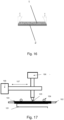
- the sealing tool consists of many individual rails 31, 41 which have the same triangular shape and are arranged next to one another in a comb-like manner at constant distances.
- the rails 31, 41 are fixed with their supports 32, 42 on a metal holder 51, which in turn can be moved linearly and/or rotationally into the plane of the adhesive tapes.
- This holder 51 can be heated and passes the heat on to the individual rails 31, 41.
- the holder 51 is fixed, but the guide of the individual strips can be changed so that they can be immersed in any depth of the sealing tool. If desired, different lengths of the contact surfaces of the adhesive tapes can therefore be easily set within the sealing tool.
- both the guide of the strip and the sealing tool are mounted in a changeable manner.
- the invention further relates to an adhesive tape, in particular cable wrapping tape, which is in particular produced according to the method according to the invention, wherein this adhesive tape comprises a strip-shaped textile carrier and a one-sided adhesive coating as well as two cut edges on the edge. According to the invention, the cut edges are fused and are lint- and thread-free when the adhesive tape rolls are unrolled.
- the textile carriers 1 of the adhesive tapes have a tapered bevel in the direction of the top side, i.e. in the direction of the side that is free of adhesive in the case of single-sided adhesive tapes.
- the cut edge of the adhesive layer 2 remains free of a bevel.
- the angle of the bevel relative to the cutting edge is half of the central angle ⁇ .
- this bevel angle ⁇ /2 is between 20° and 75°.
- all textile carrier materials are suitable as carriers, preference being given to stitch-bonded fabrics, i.e. textile fabrics that are produced by stitching integrated knitting threads into a flat base material, and particularly preferred are nonwoven stitch-bonded fabrics, i.e. textile fabrics with nonwoven fabric as the base material, which are consolidated by stitching integrated knitting threads (for example Maliwatt).
- textile carrier or "textile fabric” includes all known textile carriers such as scrims, braids, needle-punched textiles, felts, fabrics (including plain, twill and satin weaves) or nonwovens, whereby “nonwoven” is understood to mean at least textile fabrics in accordance with EN 29092 (1988) as well as stitch-bonded nonwovens and similar systems.
- Stitch-bonded fabrics also include thread layer stitch-bonded fabrics, i.e. textile fabrics with one or more superimposed thread layers as the base material, which are consolidated by the formation of stitches of integrated knitting threads, for example Florofol, pile thread stitch-bonded fabrics, i.e. textile fabrics in which knitting threads are formed as a pile and incorporated into a base material by means of stitch formation, for example Malipol and weft pile stitch-bonded fabrics, i.e. textile fabrics in which unmeshed threads formed as a pile are bound to a base material by means of knitting threads by means of stitch formation, for example weft pile.
- thread layer stitch-bonded fabrics i.e. textile fabrics with one or more superimposed thread layers as the base material, which are consolidated by the formation of stitches of integrated knitting threads, for example Florofol, pile thread stitch-bonded fabrics, i.e. textile fabrics in which knitting threads are formed as a pile and incorporated into a base material by means of stitch formation, for example Malipol and weft pile
- nonwoven fabrics i.e. textile sheet structures that are produced without the use of threads by forming fiber meshes from pre-prepared fiber fleece.
- fiber nonwoven fabrics i.e. textile sheet structures made of fiber fleece with a strengthening fiber mesh side and a side with fibers arranged horizontally to the fiber mesh layer, with fibers from the fiber fleece being formed into fiber meshes, for example Malivlies
- pile fiber nonwoven fabrics i.e. textile sheet structures made of fiber fleece with or without the use of a base material, which consist of a fiber mesh side and a pile fiber side with fibers arranged almost perpendicular to the fiber mesh layer, for example Voltex, Kunit or Maliknit
- mesh nonwoven fabrics i.e. textile sheet structures made of a pile fiber nonwoven fabric, from whose pile fibers a second fiber mesh layer is formed, for example Multiknit or Optiknit.
- Nonwovens can be made from solidified staple fiber fleeces and also filament, meltblown and spunbonded fleeces, which usually need to be additionally solidified.
- Mechanical, thermal and chemical solidification are known as possible solidification methods for nonwovens. In mechanical solidification, the fibers are usually held together purely mechanically by swirling the individual fibers, intermeshing fiber bundles or sewing in additional threads.
- Adhesive (with binder) or cohesive (binder-free) fiber-fiber bonds can be achieved using thermal and chemical processes. With suitable formulation and process control, these can be restricted exclusively or at least predominantly to fiber nodes, so that a stable, three-dimensional network is formed while maintaining the loose, open structure in the fleece.
- Such consolidated fleeces are produced, for example, on stitch-bonding machines of the "Malimo" type from Karl Mayer, formerly Malimo, and can be obtained from Tenowo GmbH, among others.
- a Malivlies is characterized by the fact that a cross-fiber fleece is consolidated by the formation of stitches from the fibers of the fleece.
- a fleece of the Kunit or Multiknit type can also be used as a carrier.
- a Kunit fleece is characterized by the fact that it is produced by processing a longitudinally oriented fiber fleece into a fabric that has stitches on one side and stitch bars or pile fiber folds on the other, but has neither threads nor prefabricated fabrics. This type of fleece has also been produced for a long time on stitch-bonding machines of the "Malimo" type from Karl Mayer, for example. Another characteristic feature of this fleece is that, as a longitudinal fiber fleece, it can absorb high tensile forces in the longitudinal direction.
- a Multiknit fleece is characterized by the fact that the fleece is strengthened by piercing both sides with needles on both the top and bottom.
- the starting product for a Multiknit is usually one or two one-sidedly meshed pile fiber fleece fabrics produced using the Kunit process.
- both nonwoven fabric surfaces are formed into a closed surface by fiber meshes and connected to each other by almost vertical fibers.
- the additional ability to incorporate other pierceable surface structures and/or scatterable media is possible.
- stitch-bonded fleeces are also particularly suitable.
- a stitch-bonded fleece is made from a fleece material with a large number of parallel seams. These seams are created by Sewing or stitch-bonding continuous textile threads.
- stitch-bonding machines of the type "Malimo" from Karl Mayer are known.
- Needle-punched nonwovens are also suitable. With needle-punched nonwovens, a fiber pile is formed into a flat structure using barbed needles. By alternately inserting and removing the needles, the material is solidified on a needle bar, whereby the individual fibers intertwine to form a solid flat structure.
- the number and design of the needling points determine the strength and stability of the fiber structures, which are usually light, permeable to air and elastic.
- a staple fiber fleece which is pre-consolidated in the first step by mechanical processing or which is a wet fleece which has been laid hydrodynamically, wherein between 2 wt.% and 50 wt.% of the fibers of the fleece are melt fibers, in particular between 5 wt.% and 40 wt.% of the fibers of the fleece.
- Such a nonwoven fabric is characterized in that the fibers are laid wet or, for example, a staple fiber nonwoven fabric is pre-consolidated by forming meshes from fibers of the nonwoven fabric by needling, sewing, air and/or water jet processing.
- thermofixing takes place, whereby the strength of the fleece is further increased by melting or melting the melt fibers.
- the adhesive consolidation of mechanically pre-consolidated or wet-laid nonwovens is of particular interest, whereby this can be achieved by adding binding agents in solid, liquid, foamed or pasty form.
- binding agents in solid, liquid, foamed or pasty form.
- solid binding agents as powder for trickling in, as film or as a grid or in the form of binding fibers.
- Liquid binding agents can be applied dissolved in water or organic solvents or as a dispersion.
- Binding dispersions are predominantly chosen for adhesive consolidation: thermosets in the form of phenol or melamine resin dispersions, elastomers as dispersions of natural or synthetic rubbers or mostly dispersions of thermoplastics such as acrylates, vinyl acetates, polyurethanes, styrene-butadiene systems, PVC and the like, as well as their copolymers. Normally these are anionic or non-ionic stabilized dispersions, but in special cases cationic dispersions can also be advantageous.
- binding agent application can be carried out according to the state of the art and can be found, for example, in standard works on coating or nonwoven technology such as "Vliesstoffe” (Georg Thieme Verlag, Stuttgart, 1982) or “Textiltechnik-Vliesstoffermaschineung” (Arbeitgebernikovicnikil, Eschborn, 1996).
- the one-sided spray application of a binding agent is recommended in order to specifically change the surface properties.
- this method of operation also significantly reduces the energy required for drying. Since no squeezing rollers are required and the dispersions remain mainly in the upper area of the nonwoven fabric, undesirable hardening and stiffening of the nonwoven fabric can be largely prevented.
- binding agent in the order of 1% to 50%, in particular 3% to 20%, based on the weight of the nonwoven fabric, must generally be added.
- the binder can be added during the fleece production process, during mechanical pre-consolidation or in a separate process step, which can be carried out in-line or offline. After the binder has been added, a state must be temporarily created for the binder in which it becomes sticky and adhesively bonds the fibers - this can be achieved during the drying of dispersions, for example, but also by heating, with further variation options being available through the application of surface or partial pressure.
- the activation of the binder can take place in known drying channels, but with a suitable selection of binder also by means of infrared radiation, UV radiation, ultrasound, high-frequency radiation or the like.
- Another special form of adhesive bonding is that the binding agent is activated by dissolving or swelling.
- the fibers themselves or special fibers mixed in can also take on the function of the binding agent.
- solvents are environmentally questionable or problematic to handle for most polymer fibers, this process is rarely used.
- the thread count in the warp is 20 to 40/cm, preferably 20 to 30cm.
- the thread count in the weft is 14 to 26/cm, preferably 16 to 22/cm.
- the fabric is a polyester fabric, a mixed fabric of polyester and polyamide or a mixed fabric of yarns where polyester and polyamide are formed as a mixed thread.
- the thickness of the fabric is a maximum of 400 ⁇ m, particularly preferably 220 to 310 ⁇ m, most preferably 260 to 300 ⁇ m.
- Spacer fabrics and knitted fabrics with lamination can also be used.
- Spacer fabrics are double-faced textiles in which the warp-knitted fabric surfaces are kept at a distance by spacer-maintaining connecting threads, so-called pile threads.
- Spacer fabrics are knitted fabrics that have been expanded to include a third dimension. Spacer fabrics also have two spaced-apart fabric layers that are kept at a distance by filaments, threads or fibers. Such spacer fabrics are used in the EP 0 071 212 B1 revealed.
- the carrier can have a smooth-ground surface on one or both sides, preferably a completely smooth-ground surface.
- the smooth-ground surface may be chintzed, as is the case, for example, in the EP 1 448 744 A1 is explained in detail.
- the carrier can be calendered in a rolling mill for compaction.
- the two rollers run in opposite directions and at the same peripheral speed so that the carrier is pressed and compacted.
- the carrier is additionally ground smooth.
- the textile carrier of the adhesive tape has a basis weight of up to 300 g/m 2 , preferably 125 to 200 g/m 2 .
- Fibers staple fibers or continuous filaments made of a thermoplastic material are used as starting materials for the carrier material of the adhesive tape.
- the proportion of thermoplastic fibers in the carrier material is preferably at least 50 wt.% or more, more preferably 70 wt.% or more, more preferably 90 wt.% or more, more preferably 100 wt.%.
- thermoplastic fibers or filaments are preferably made of polyester (for example PET (polyethylene terephthalate) or PBT), (non-aromatic) polyamide (for example polyamide 6, polyamide 6.6, polyamide 4.6 or other polyamides).
- polyester for example PET (polyethylene terephthalate) or PBT
- non-aromatic polyamide for example polyamide 6, polyamide 6.6, polyamide 4.6 or other polyamides.
- Polyolefins such as polyethylene (PE (PE-LD, PE-HD)) or polypropylene (PP), polyphthalamides (PPA, partially aromatic polyamides) or PVC are also suitable.
- the fibers and/or filaments of the textile carrier material preferably contain polyamide or polyester such as polyethylene terephthalate, preferably they consist of each of these.
- polyamide or polyester such as polyethylene terephthalate
- pure thermoplastics are preferably used to form the fibers or filaments, i.e. only PET or polyamide. Mixtures of the thermoplastics listed are also possible, with pure yarns being used alternately or in the form of mixed yarns. In mixed yarns, different types of polymers are combined or twisted to form a yarn.
- the batch of (chemical) fibers (staple fiber or continuous filament) mixed with the thermoplastics comprises non-thermoplastic plastics and (chemical) fibers made from natural polymers such as cellulosic fibers (viscose, modal, lyocell, cupro, acetate, triacetate, cellulon), rubber fibers, plant protein fibers and/or animal protein fibers and/or natural fibers made from cotton, sisal, flax, silk, hemp, linen, coconut or wool.
- cellulosic fibers viscose, modal, lyocell, cupro, acetate, triacetate, cellulon
- rubber fibers such as cellulosic fibers (viscose, modal, lyocell, cupro, acetate, triacetate, cellulon), rubber fibers, plant protein fibers and/or animal protein fibers and/or natural fibers made from cotton, sisal, flax, silk, hemp, linen, coconut or wool.
- the present invention is not limited to the materials mentioned
- yarns made from the specified fibers are also suitable.
- the additional sewing threads which are required for a nonwoven sewing fabric, for example, can consist of the polymers mentioned. Sewing threads made of polyethylene terephthalate or polyamide are preferred.
- individual threads can be made from a mixed yarn.
- the warp threads and weft threads are usually made from a single type of yarn.
- the warp threads and/or the weft threads in woven or non-woven fabrics can consist of 100% by weight of thermoplastic threads. It is also possible for only the warp threads or only the weft threads to consist of 100% by weight of thermoplastic threads, with the proportion of thermoplastic fibers in the fabric preferably being at least 50% by weight.
- the yarns or threads of the fabrics can be in the form of filaments.
- a filament is understood to be a bundle of parallel, straight individual fibers/individual filaments, often referred to in the literature as a multifilament. If necessary, this fiber bundle can be consolidated by twisting; in this case, it is referred to as spun or twisted filaments. Alternatively, the fiber bundle can be consolidated by swirling with compressed air or a water jet. In the following, the term filament is used for all of these embodiments in general terms.
- the filament can be textured or smooth and point-solidified or unsolidified.
- the fibres in particular those used for nonwoven formation, preferably have a fibre thickness of 1.5 to 5.5 dtex and/or a fibre length of 30 to 90 mm.
- the number of sewing threads is preferably in the range of 15 to 25 threads/25 mm.
- the basis weight of the textile carrier is advantageously between 30 g/m 2 and 300 g/m 2 , whereby the two limit values mentioned are explicitly included in the range specification (this also applies to all of the following parameter ranges listed mutatis mutandis), further advantageously between 50 g/m 2 and 200 g/m 2 , particularly advantageous between 50 g/m 2 and 200 g/m 2 , very particularly advantageous between 70 g/m 2 and 190 g/m 2 .
- the basis weight is preferably 50 g/m 2 to 200 g/m 2 , in particular 175 g/m 2 .
- the basis weight is preferably 50 g/m 2 to 200 g/m 2 , more preferably 70 g/m 2 to 190 g/m 2 .
- the textile carriers have a flexural rigidity in the range of 0 to 30 mN/60 mm as a textile carrier before the adhesive coating (MD, machine direction), optionally from 2 to 30 mN/60 mm as a textile carrier before the adhesive coating (MD), from which very good flagging-free adhesive tapes are obtained.
- the adhesive application is preferably between 300 and 160 g/m 2 , preferably between 50 and 100 g/m 2 , more preferably between 60 and 90 g/m 2 .
- the adhesive is preferably a pressure-sensitive adhesive, i.e. an adhesive that allows a permanent bond to almost all adhesive substrates even under relatively light pressure and can be removed from the adhesive substrate after use without leaving any residue.
- a pressure-sensitive adhesive is permanently tacky at room temperature, i.e. has a sufficiently low viscosity and a high tackiness so that it wets the surface of the respective adhesive substrate even under light pressure.
- the ability of the adhesive to bond is based on its adhesive properties and the ability to be removed again is based on its cohesive properties.
- Pressure-sensitive adhesives can be considered as extremely viscous liquids with an elastic component. Pressure-sensitive adhesives therefore have special, characteristic viscoelastic properties that lead to their permanent inherent tack and adhesive properties.
- the proportion of viscous flow is necessary to achieve adhesion. Only the viscous components, caused by macromolecules with relatively high mobility, enable good wetting and good flow onto the substrate to be bonded. A high proportion of viscous flow leads to high adhesive strength (also known as tack or surface stickiness) and thus often to high adhesive strength. Strongly cross-linked systems, crystalline or glass-like solidified polymers are generally not adhesive or at least only slightly adhesive due to the lack of flowable components.
- the proportional elastic restoring forces are necessary to achieve cohesion. They are caused, for example, by very long-chain and highly entangled macromolecules as well as by physically or chemically cross-linked macromolecules and enable the transfer of the forces acting on an adhesive bond. They mean that an adhesive bond can withstand a permanent load acting on it, for example in the form of a permanent shear load, to a sufficient extent over a longer period of time.
- the polymer consists of 95.0 to 99.5 wt.% n-butyl acrylate and/or 2-ethylhexyl acrylate and 0.5 to 5 wt.% of an ethylenically unsaturated monomer having an acid or acid anhydride function, more preferably of 97.0 or 98.0 wt.% to 99.0 wt.% n-butyl acrylate and/or 2-ethylhexyl acrylate and 1.0 to 2.0 wt.% or 3 wt.% of an ethylenically unsaturated monomer having an acid or acid anhydride function.
- tackifiers and/or additives such as light stabilizers or anti-aging agents can be added to the pressure-sensitive adhesive in addition to any residual monomers that may be present.
- the polymers of the pressure-sensitive adhesive consist only of the monomers (a) and (b) in the stated proportions.
- n-butyl acrylate forms the monomer (a).
- Advantageous monomers (b) include, for example, acrylic acid, methacrylic acid, itaconic acid, maleic acid, fumaric acid and/or maleic anhydride.
- the polymer dispersion is prepared by the process of emulsion polymerization of the above-mentioned components. Descriptions of this process can be found, for example, in " Emulsion Polymerization and Emulsion Polymers” by Peter A. Lovell and Mohamed S. El-Aasser - Wiley-VCH 1997 - ISBN 0-471-96746-7 or in EP 1 378 527 B1 .
- adhesive compositions comprising the polymer dispersion with a residual monomer content of less than or equal to 1 wt. %, in particular less than or equal to 0.5 wt. % (based on the mass of the dried polymer dispersion) are provided.
- an “adhesive resin” is understood to mean an oligomeric or polymeric resin that increases the autoadhesion (the tack, the inherent stickiness) of the pressure-sensitive adhesive compared to the pressure-sensitive adhesive that does not contain an adhesive resin but is otherwise identical.
- tackifiers to increase the adhesive strength of pressure-sensitive adhesives is generally known. This effect also occurs when up to 15 parts by weight (corresponds to ⁇ 15 parts by weight) or 5 to 15 parts by weight of tackifier (based on the mass of the dried polymer dispersion) are added to the adhesive. Preferably 5 to 12, more preferably 6 to 10 parts by weight of tackifier (based on the mass of the dried polymer dispersion) are added.
- tackifiers also known as adhesive resins.
- tackifiers are hydrocarbon resins (e.g. polymers based on unsaturated C 5 or C 9 monomers), terpene phenol resins, polyterpene resins based on raw materials such as ⁇ - or ⁇ -pinene, aromatic resins such as coumarone-indene resins or resins based on styrene or ⁇ -methylstyrene such as rosin and its derivatives, for example disproportionated, dimerized or esterified rosin, for example reaction products with glycol, glycerin or pentaerythritol, to name just a few.
- hydrocarbon resins e.g. polymers based on unsaturated C 5 or C 9 monomers
- terpene phenol resins terpene resins
- polyterpene resins based on raw materials such as ⁇ - or ⁇ -pinene
- aromatic resins such as coumarone-inden
- resins without easily oxidizable double bonds such as terpene phenol resins, aromatic resins and particularly preferred resins produced by hydrogenation such as hydrogenated aromatic resins, hydrogenated polycyclopentadiene resins, hydrogenated rosin derivatives or hydrogenated polyterpene resins.
- Resins based on terpene phenols and rosin esters are preferred. Adhesive resins with a softening point above 80 °C according to ASTM E28-99 (2009) are also preferred. Resins based on terpene phenols and rosin esters with a softening point above 90 °C according to ASTM E28-99 (2009) are particularly preferred.
- the resins are expediently used in dispersion form. They can then be easily mixed with the polymer dispersion to form a finely distributed mixture.
- solvent-free acrylic hot melt compounds are to be preferred, as they are used in DE 198 07 752 A1 as well as in DE 100 11 788 A1 are described in more detail.
- Fogging is the effect that, under unfavorable conditions, low-molecular compounds can outgas from the adhesive tapes and condense on cold parts. This can, for example, impair visibility through the windshield.
- a suitable adhesive composition is one based on acrylate hotmelt which has a K value of at least 20, in particular greater than 30 (measured in each case in 1 wt. % solution in toluene, 25°C), obtainable by concentrating a solution of such a composition to a system which can be processed as a hotmelt.
- Concentration can take place in appropriately equipped kettles or extruders; a degassing extruder is preferred, especially for the associated degassing.
- the K-value is determined in particular in analogy to DIN 53 726.
- the solution of the mass can contain 5 to 80% by weight, in particular 30 to 70% by weight, of solvent.
- solvents are preferably used, in particular low-boiling hydrocarbons, ketones, alcohols and/or esters.
- single-screw, twin-screw or multi-screw extruders with one or in particular two or more degassing units are preferably used.
- Benzoin derivatives can be polymerized into the acrylic hotmelt-based adhesive, such as benzoin acrylate or benzoin methacrylate, acrylic acid or methacrylic acid esters.
- benzoin derivatives are in the EP 0 578 151 A described.
- the adhesive based on acrylate hot melt can be UV crosslinked.
- other types of crosslinking are also possible, such as electron beam crosslinking.
- copolymers of (meth)acrylic acid and its esters having 1 to 25 carbon atoms, maleic, fumaric and/or itaconic acid and/or its esters, substituted (meth)acrylamides, maleic anhydride and other vinyl compounds, such as vinyl esters, in particular vinyl acetate, vinyl alcohols and/or vinyl ethers, are used as self-adhesive compositions.
- the residual solvent content should be less than 1 wt.%.
- One adhesive that has proven to be particularly suitable is a low molecular weight acrylic hot melt pressure sensitive adhesive, such as that sold by BASF under the name acResin UV or Acronal ® , in particular acResin A 260UV.
- acResin UV or Acronal ® sold by BASF under the name acResin UV or Acronal ® , in particular acResin A 260UV.
- This adhesive with a low K value obtains its application-appropriate properties through a final radiation-chemically triggered crosslinking process.
- the adhesive coating also preferably consists of an adhesive based on synthetic rubber, namely in particular an adhesive made of at least one vinyl aromatic block copolymer and at least one adhesive resin.
- Typical use concentrations for the block copolymer are in a concentration in the range between 30 wt.% and 70 wt.%, in particular in the range between 35 wt.% and 55 wt.%.
- polymers that may be present are those based on pure hydrocarbons, such as unsaturated polydienes such as natural or synthetically produced polyisoprene or polybutadiene, chemically essentially saturated elastomers such as saturated ethylene-propylene copolymers, ⁇ -olefin copolymers, polyisobutylene, butyl rubber, ethylene-propylene rubber, and chemically functionalized hydrocarbons such as halogen-containing, acrylate-containing or vinyl ether-containing polyolefins, which can replace up to half of the vinylaromatic-containing block copolymers.
- unsaturated polydienes such as natural or synthetically produced polyisoprene or polybutadiene
- chemically essentially saturated elastomers such as saturated ethylene-propylene copolymers, ⁇ -olefin copolymers, polyisobutylene, butyl rubber, ethylene-propylene rubber
- chemically functionalized hydrocarbons such as halogen-containing
- Tackifiers used are adhesive resins that are compatible with the elastomer block of the styrene block copolymers.
- Plasticizers such as liquid resins, plasticizer oils or low molecular weight liquid polymers such as low molecular weight polyisobutylenes with molecular weights ⁇ 1500 g/mol (number average) or liquid EPDM types are typically used.
- light stabilizers such as UV absorbers, sterically hindered amines, antiozonants, metal deactivators, processing aids and endblock reinforcing resins.
- Fillers such as silicon dioxide, glass (ground or in the form of spheres as solid or hollow spheres), microballoons, aluminum oxides, zinc oxides, calcium carbonates, titanium dioxides, carbon blacks, silicates and chalk, to name just a few, as well as color pigments and dyes as well as optical brighteners can also be used.
- Primary and secondary antioxidants are usually added to pressure-sensitive adhesives to improve their aging stability.
- Primary antioxidants react with oxy and peroxy radicals that can form in the presence of oxygen, and react with these to form less reactive compounds.
- Secondary antioxidants reduce hydroperoxides to alcohols, for example. It is known that there is a synergistic effect between primary and secondary anti-aging agents, so that the protective effect of a mixture is often greater than the sum of the two individual effects.
- flame retardancy of the adhesive tape described can be achieved by adding flame retardants to the carrier and/or the adhesive.
- flame retardants can be organobromine compounds, if necessary with synergists such as antimony trioxide, although in view of the halogen-free nature of the adhesive tape, red phosphorus, organophosphorus, mineral or intumescent compounds such as ammonium polyphosphate are preferred, either alone or in combination with synergists.
- the PSAs can be manufactured and processed from solution, dispersion or from the melt.
- Preferred manufacturing and processing methods are from the melt.
- suitable manufacturing processes include both batch processes and continuous processes.
- adheresive tape in the sense of this invention includes all flat structures such as films or film sections extended in two dimensions, tapes with extended length and limited width, tape sections and the like, and ultimately also die-cuts or labels.
- the adhesive tape therefore has a longitudinal dimension and a width dimension.
- the adhesive tape also has a thickness running perpendicular to both dimensions, whereby the Width and length are many times greater than the thickness.
- the thickness is as uniform as possible, preferably exactly the same, over the entire surface area of the adhesive tape, determined by length and width.
- the adhesive tape is in particular in the form of a web.
- a web is understood to be an object whose length is many times greater than its width and whose width is approximately, preferably exactly the same, along its entire length.
- a backing coat (functional layer) can be applied to the exposed upper side of the carrier in order to positively influence the unwinding properties of the adhesive tape wound into an Archimedean spiral.
- This backing coat can contain silicone or fluorosilicone compounds as well as polyvinyl stearyl carbamate, polyethyleneimine stearyl carbamide or fluoroorganic compounds as dehesive substances.
- the adhesive can be applied in the longitudinal direction of the adhesive tape in the form of a strip which has a smaller width than the first carrier.
- the position of the strip on the carrier can be freely selected, although an arrangement directly on one of the edges of the carrier is preferred.
- the adhesive is applied over the entire surface of the first carrier.
- At least one strip of covering may be provided on the adhesive coating of the carrier, which strip or strips extend in the longitudinal direction of the adhesive tape and which cover between 20% and 90% of the adhesive coating.
- the strip covers between 50% and 80% of the adhesive coating.
- the degree of coverage is selected depending on the application and the diameter of the cable harness.
- the percentages given refer to the width of the covering strips in relation to the width of the support.
- exactly one strip of the covering is present on the adhesive coating.
- the position of the strip on the adhesive coating is freely selectable, although an arrangement directly on one of the longitudinal edges of the carrier is preferred. This creates an adhesive strip that extends in the longitudinal direction of the adhesive tape and ends at the other longitudinal edge of the carrier.
- the adhesive tape is used to cover a wiring harness by guiding the adhesive tape around the wiring harness in a helical motion, the covering of the
- the wiring harness should be glued in such a way that the adhesive of the tape is only bonded to the tape itself, while the goods do not come into contact with any adhesive.
- the cable harness covered in this way is very flexible because the cables are not fixed with any kind of adhesive. This significantly increases its bending ability during installation - especially in narrow passages or sharp bends.
- the wrapping can be done in such a way that the adhesive strip is partly stuck to the adhesive tape itself and partly to the goods.
- the strip is applied centrally to the adhesive coating, so that two adhesive strips are formed on the longitudinal edges of the carrier extending in the longitudinal direction of the adhesive tape.
- the two adhesive strips on the long edges of the adhesive tape are advantageous for the safe and economical application of the adhesive tape in the aforementioned helical movement around the cable harness and to prevent the resulting protective covering from slipping, especially if one, which is usually narrower than the second strip, serves as a fixing aid and the second, wider strip serves as a closure. In this way, the adhesive tape is stuck to the cable in such a way that the cable set is secured against slipping and yet is still flexible.
- the manufacturing process of the adhesive tape according to the invention consists in coating the carrier directly or by transfer with a suitable adhesive in one or more successive operations.
- the textile carrier can be pre-treated with a coating (with any film-forming substance from solution, dispersion, melt and/or radiation-curing) in order to then be provided with the pressure-sensitive adhesive in a subsequent work step directly or by transfer.
- a coating with any film-forming substance from solution, dispersion, melt and/or radiation-curing
- the usual application units are used: wire doctor blade, coating bar, roller application, nozzle coating, double-chamber doctor blade, multiple cascade nozzle.
- the adhesive mass has sunk into the carrier by more than 10%, preferably more than 25%, more preferably more than 50% after application to the carrier.
- a numerical value of, for example, 25% means that the Adhesive has penetrated over a layer thickness of 25% of the thickness of the textile carrier, i.e. in the case of a carrier with a thickness of 100 ⁇ m over a layer thickness of 25 ⁇ m within the carrier, starting from the surface of the carrier on which the adhesive is coated and in a direction perpendicular to the plane spanned by the longitudinal or transverse direction.
- the adhesive tape can be used excellently for insulating and wrapping wires or cables.
- the adhesive tape is preferably used to wrap elongated items, such as cable harnesses in particular, whereby the adhesive tape is guided around the elongated item in a helical movement.
- a helix also called a screw, helical line, cylindrical spiral or helix; a helix is a curve that winds around the shell of a cylinder at a constant pitch).
- the elongated material is wrapped in the axial direction by the adhesive tape.
- the wrapping of a cable harness with the adhesive tape described is not done in a helical manner - as is usual - but in such a way that a longitudinal axis of the tape is essentially aligned parallel to the direction of the cable harness when wrapping.
- the adhesive tape is in the form of an Archimedean spiral around the cable harness. This type of winding is also called "wrapping the cable harness".
- This cutting process in which the cutting edges are sealed, can be used to assemble coated adhesive tapes and uncoated textile carriers. Both materials are required and used for the manufacture of products for the longitudinal wrapping of cable harnesses.
- the provision of adhesive tapes with a particularly large uninterrupted length is no longer possible with plate rolls in the form of an Archimedean spiral.
- the assembly usually takes place in the form of a spool that is many times the width of the adhesive tape and the adhesive tape is wound up in a helical winding in a large number of layers.
- the adhesive layer of the upper layer often lies on the cutting edges of the lower layer and the cutting edges are subjected to particular stress.
- a particularly strong cutting edge is desirable here in order to avoid the pulling out of fibers/filaments.
- An adhesive tape produced in this form of assembly using the method described in claim 1 has also proven to be positive and advantageous.
- a sheathed elongated product such as in particular a cable harness, sheathed with an adhesive tape according to the invention, as well as a vehicle containing such a sheathed elongated product.
- the elongated item is a cable harness comprising a bundle of several cables, such as 3 to 1000 cables, preferably 10 to 500 cables, in particular between 50 and 300 cables.
- the adhesive tape can be used in a sheathing consisting of a covering in which the self-adhesive adhesive tape is present at least in one edge area of the covering, which is bonded to the covering in such a way that the adhesive tape extends over one of the longitudinal edges of the covering, preferably in an edge area that is narrow compared to the width of the covering.
- At least one longitudinal marking line can be present on the top of the carrier. Two marking lines are preferred. These marking lines differ visually and/or haptically from the surrounding surface.
- the marking is applied to the carrier, for example by printing.
- the marking can be incorporated into the first carrier. In this way, the marking can be implemented as a woven-in warp thread.
- the EP 3 245 265 A1 describes the use of such a marking line on an adhesive tape.
- perforations are provided in the adhesive tape, which are aligned at right angles to the running direction of the adhesive tape and/or arranged at regular intervals.
- the perforation serves primarily as a tear-off aid for cutting to the specified length. There should be no perforations in the piece of adhesive tape that covers the goods in order to avoid mechanical weakening of the wrapping during transport and installation.
- the perforations can be produced discontinuously with flat punches or transverse perforation wheels as well as continuously using rotary systems such as spiked rollers or punching rollers, if necessary using a counter roller (Vulkollan roller), which forms the counter wheel during cutting.
- rotary systems such as spiked rollers or punching rollers, if necessary using a counter roller (Vulkollan roller), which forms the counter wheel during cutting.
- perforation include controlled intermittent cutting technologies such as the use of lasers, ultrasound, high-pressure water jets, etc.
- the adhesive tape can be used flexibly on different cable diameters.
- the advantageous labeling makes it safe and easy to check that the adhesive tape has been used correctly.
- the adhesive tape according to the invention can be applied in the known and usual processes for cable bandaging.
- the adhesive tape is shown in cross-section, which consists of a fabric carrier 1, to which a layer of a self-adhesive coating 2 based on an acrylate dispersion is applied on one side.
- the adhesive has sunk 20% into the carrier, which ensures optimal anchoring and at the same time improves the hand tearability of the carrier.
- FIG. 2 a section of a cable harness is shown, which is composed of a bundle of individual cables 7 and which is covered with the adhesive tape 11 according to the invention.
- the adhesive tape is guided around the cable harness in a helical movement.
- the section of the wiring harness shown shows two windings I and II of the adhesive tape. Further windings would extend to the left, but these are not shown here.
- two tapes 60, 70 according to the invention provided with an adhesive are laminated to one another with their adhesives offset (preferably by 50% each), so that a product is obtained as shown in Figure 3 is shown.
- the adhesive tape is described below in a preferred embodiment, without wishing to subject the invention to any limitation.
- An acrylate-based pressure-sensitive adhesive is applied to a nonwoven carrier, resulting in an adhesive basis weight of 65 g/m 2 .
- the fleece is a stitch-bonded fleece of the Maliwatt type with a basis weight of 72 g/m 2 , consisting of pure PET fibres with a length of 64 mm and a thickness of 3.3 dtex and a PET sewing thread with a thickness of 50 dtex, which are sewn with (22 threads per inch (corresponds to 9 threads/centimeter of fleece width).
- This fleece-based adhesive tape can be processed using the process, which prevents thread tearing and lint contamination when unrolling the adhesive tape.
- An acrylate-based pressure-sensitive adhesive is applied to a polyamide fabric, resulting in an adhesive weight of 100 g/m 2.
- the polyamide fabric is made of untwisted polyamide yarns, type polyamide 6.6 with 470 dtex.
- the number of threads is 21 threads/cm in the warp direction and 17 threads/cm in the weft direction. Without special treatment of the cutting edges, this adhesive tape tends to tear the warp threads and form lint.
- This fabric-based adhesive tape can be processed using the process, which prevents thread tears and lint contamination when unrolling the adhesive tape.
- An acrylate-based pressure-sensitive adhesive is applied to another polyamide fabric, resulting in an adhesive weight of 80 g/m 2.
- the polyamide fabric consists of untwisted polyamide yarns in the warp direction, type polyamide 6.6 with 270 dtex, and in the weft direction the fabric consists of twisted mixed yarns of polyamide 6.6 with 270 dtex and polyethylene terephthalate with 167 dtex.
- the number of threads is 29 threads/cm in the warp direction and 22 threads/cm in the weft direction. Without special treatment of the cutting edges, this adhesive tape tends to tear the warp threads and form lint.
- This fabric-based adhesive tape can be processed using the process, which prevents thread tears and lint contamination when unrolling the adhesive tape.
- An acrylate-based pressure-sensitive adhesive is applied to a polyester fabric, resulting in an adhesive weight of 80 g/m 2.
- the polyester fabric is made of polyethylene terephthalate yarns with 167 dtex.
- the number of threads is 48 threads/cm in the warp direction and 26 threads/cm in the weft direction. Without special treatment of the cutting edges, this adhesive tape tends to tear the warp threads and form lint.
- This fabric-based adhesive tape can be processed using the process, which prevents thread tears and lint contamination when unrolling the adhesive tape.
- An acrylate-based pressure-sensitive adhesive is applied to a velour carrier, resulting in an adhesive mass per unit area of 70 /m 2 .
- the velour is a warp-knitted fabric made of polyamide yarns, type polyamide 6.6, which is roughened on one side in a second work step.
- This velour-based adhesive tape cannot be processed using this method; it tends to stretch under tensile stress during the cutting process and to reduce the width of the strip. The cutting edges cannot be safely guided past the heated elements.
- An acrylate-based pressure-sensitive adhesive is applied to an aramid fabric, resulting in an adhesive basis weight of 80 /m 2 .
- the aramid fabric is made of aramid yarns, type para-aramid with 420 dtex.
- the thread count is 13 threads/cm in the warp and weft direction.
- This aramid-based adhesive tape cannot be processed using this method; even at very high temperatures on the heated elements, sealed edges are not achieved.
- the sealing tool which consists of 55 triangular-shaped rails made of aluminum nitride.
- the distance between the rails is 15 mm.
- the rails have a surface temperature of 350 °C.
- the adhesive tapes are fed through the sealing tool at a web speed of 0.75 m/s, with the contact surface of the cut edge on the rails having a length of 85 mm.
- Example A Example B Example C Description textile carrier of the adhesive tape Sewing fleece PET fiber and PET sewing thread 72 g/m2 Polyamide fabric made of untwisted polyamide yarns, construction 21 ⁇ 17 threads/cm at 185 g/m 2 Polyamide blended fabric with the construction 29 ⁇ 22 threads/cm warp PA untwisted and weft PA-PET twisted yarns Description Adhesive coating Acrylic adhesive with 65 g/m 2 Acrylic adhesive with 100 g/m 2 Acrylic adhesive with 80 g/m 2 Basis weight of the adhesive tape 137 g/ m2 285g/ m2 265g/ m2 Width of the adhesive tape after cutting 19mm 19mm 19mm Thickness of the adhesive tape 270 ⁇ m 380 ⁇ m 370 ⁇ m Adhesive strength according to DIN EN ISO 29862 on steel 2.6N/cm 3.1N/cm 2.8N/cm Abrasion according to VW 60360-1 2022-
- the measurements are carried out in a test climate of 23 ⁇ 1 °C and 50 ⁇ 5 % relative humidity.
- the abrasion resistance of an adhesive tape is determined according to the test guideline mentioned using a defined test procedure.
- the classification of the adhesive tapes in terms of their abrasion resistance is shown in Table 1 for a mandrel diameter of 5 mm.
- Table 1 Classification of abrasion resistance of adhesive tapes according to VW 60360-1 Abrasion class single layer at RT Classification of protection class Requirement A-1L A no abrasion protection ⁇ 100 strokes B-1L B very low abrasion protection 100 - 499 strokes C-1L C low abrasion protection 500 - 999 strokes D-1L D medium abrasion protection 1000 - 4999 strokes E-1L E high abrasion protection 5000 -14999 strokes F-1L F very high abrasion protection 15000 - 29999 strokes G-1L G extreme abrasion protection 30000 - 59999 strokes H-1L H extremely high abrasion protection ⁇ 60000
- the test specimen which is 10 cm long, is placed on a 5 mm thick steel mandrel in a single layer in the lengthwise direction of the product to be tested. If the adhesive tape structure is not the same across the entire surface, the part that represents the protective function in the application is tested for abrasion.
- a steel wire with a diameter of 0.45 mm is used as the abrasion tool, which rubs over the center of the test specimen under a weight load of 7 N. The number of double strokes until the test specimen is destroyed is determined as a measure of the abrasion properties.
- the resistance to sharper objects such as a metal edge in the application can be simulated.
- the abrasion test can be carried out with several layers of adhesive tape and/or at an elevated temperature (90 °C).
- the abrasion measurement method is in the Figure 17 shown.
- the noise attenuation of an adhesive tape is determined using a defined test setup and test procedure according to the VW specification.
- a steel rod mounted on one side, is pivoted and hits a bent aluminum sheet, creating a noise.
- the difference in the noise between the steel rod and the steel rod wrapped in a protective cover describes the degree of noise dampening that a protective hose or adhesive tape can achieve.
- a defined steel rod 203 (diameter 8 mm, lever length of 220 mm) is provided with a test piece 205 - i.e. adhesive tape - and is dropped with a force of 0.16 N from a height of 20 mm, released from the locking device 205, onto an aluminum sheet 204.
- the aluminum sheet In the undeformed state, the aluminum sheet has the mass 350 ⁇ 190 ⁇ 0.3 [mm] and is arranged in a half-barrel shape under the test piece 205, resulting in a width of 290 mm.
- the resulting noise is recorded using a microphone 204 located 50 mm above the point of impact and a commercially available sound measuring device, for example type 2239 from Bruel & Kjaer, in the form of the sound pressure level (Lsp) with the frequency weighting A (frequency range from, for example, 20 to 12,500 Hz) and the time weighting S (Slow).
- Lsp sound pressure level
- A frequency range from, for example, 20 to 12,500 Hz
- S time weighting S
- the attenuation is given as the difference between the zero value with a non-wrapped steel rod and the respective measured value of the test object in dB(A).
- Table 2 Classification of noise attenuation according to VW 60360-1 Noise reduction class single layer Noise reduction class according to VW specification Measured value of noise attenuation A-1L A no noise reduction 0 to ⁇ 2 dB(A) B-1L B very low noise attenuation > 2 to ⁇ 5 dB(A) C-1L C low noise attenuation > 5 to ⁇ 10 dB(A) D-1L D medium noise attenuation > 10 to ⁇ 15 dB(A) E-1L E high noise attenuation > 15 to ⁇ 20 dB(A) F-1L F very high noise attenuation > 20 dB(A)
Landscapes
- Chemical & Material Sciences (AREA)
- Organic Chemistry (AREA)
- Engineering & Computer Science (AREA)
- Mechanical Engineering (AREA)
- Adhesive Tapes (AREA)
Applications Claiming Priority (1)
| Application Number | Priority Date | Filing Date | Title |
|---|---|---|---|
| DE102023105349.3A DE102023105349A1 (de) | 2023-03-03 | 2023-03-03 | Verfahren zum Konfektionieren von textilen Klebebändern |
Publications (1)
| Publication Number | Publication Date |
|---|---|
| EP4424496A1 true EP4424496A1 (fr) | 2024-09-04 |
Family
ID=90123694
Family Applications (1)
| Application Number | Title | Priority Date | Filing Date |
|---|---|---|---|
| EP24160746.4A Pending EP4424496A1 (fr) | 2023-03-03 | 2024-03-01 | Procédé pour la confection de bandes textiles adhésives |
Country Status (3)
| Country | Link |
|---|---|
| EP (1) | EP4424496A1 (fr) |
| CN (1) | CN118580775A (fr) |
| DE (1) | DE102023105349A1 (fr) |
Citations (28)
| Publication number | Priority date | Publication date | Assignee | Title |
|---|---|---|---|---|
| EP0071212B1 (fr) | 1981-07-27 | 1986-04-09 | Günter TESCH | Objet stratifié en forme de natte et procédé pour sa fabrication |
| EP0578151A1 (fr) | 1992-07-08 | 1994-01-12 | Beiersdorf Aktiengesellschaft | Adhésifs thermofusibles sensibles à la pression pour des produits médicaux |
| DE4313008C1 (de) | 1993-04-21 | 1994-11-10 | Beiersdorf Ag | Selbstklebemasse auf Acrylathotmelt-Basis, Verfahren zu deren Herstellung und deren Verwendung |
| DE19807752A1 (de) | 1998-02-24 | 1999-08-26 | Beiersdorf Ag | Foggingfreies Klebeband |
| DE10011788A1 (de) | 2000-03-10 | 2002-03-28 | Tesa Ag | Verwendung eines Klebebandes als Bandagierungsband für Kabel |
| EP1300452A2 (fr) | 2001-10-05 | 2003-04-09 | Tesa AG | Procédé pour enrober des produits longs |
| EP1312097A1 (fr) | 2000-07-28 | 2003-05-21 | Tesa AG | Procede servant a envelopper des objets allonges notamment des faisceaux de cables |
| EP1315781A1 (fr) | 2000-08-31 | 2003-06-04 | Tesa AG | Procede permettant d'envelopper un element allonge, en particulier un faisceau de cables, a l'aide d'une bande adhesive |
| EP1367608A2 (fr) | 2002-01-22 | 2003-12-03 | tesa AG | Procédé pour enrober des produits longs, en particulier des faisceaux de câbles, avec deux revêtements en forme de ruban, qui entourent ces produits sous forme tubulaire |
| DE10229527A1 (de) | 2002-07-01 | 2004-01-15 | Tesa Ag | Band aus einer Reihe hintereinander und überlappend angeordneter einzelner Ummantelungsabschnitte zum Ummanteln von langgestrecktem Gut, wie insbesondere Kabelsätzen |
| EP1448744A1 (fr) | 2001-10-16 | 2004-08-25 | certoplast Vorwerk & Sohn GmbH | Bande adhesive a surface support lissee |
| DE10329994A1 (de) | 2003-07-02 | 2005-01-20 | Tesa Ag | Verfahren zur Ummantelung von langgestrecktem Gut, wie insbesondere Kabelsätzen, mit einem Klebeband |
| WO2006108871A1 (fr) | 2005-04-14 | 2006-10-19 | Tesa Ag | Procede pour entourer un produit oblong, comme notamment des faisceaux de cables, d'une gaine |
| EP1848006A2 (fr) | 2006-04-20 | 2007-10-24 | Coroplast Fritz Müller GmbH & Co. KG | Bande de colle destinée à l'enrobage de biens allongés, utilisation de cette bande de colle tout comme faisceau de câble doté de cette bande de colle |
| EP1378527B1 (fr) | 2002-07-02 | 2008-11-12 | Basf Se | Adhésives sensibles à pression pour support en CPV souple |
| EP2497805A1 (fr) | 2011-03-07 | 2012-09-12 | tesa SE | Ruban adhésif pour le bandage de câbles |
| EP2520628A1 (fr) | 2011-05-03 | 2012-11-07 | tesa SE | Bande de collage destinée à l'enrobage de marchandise allongée, comme notamment des ensemble de câbles et procédé d'enrobage |
| EP2520629A1 (fr) | 2011-05-03 | 2012-11-07 | Tesa AG | Procédé de fabrication d'une bande adhésive destinée à être enroulée autour de câbles et composée d'un support textile ouvert revêtu sur l'un de ses côtés par une masse auto-collante |
| EP2520627A1 (fr) | 2011-05-03 | 2012-11-07 | Tesa AG | Bande de collage destinée à l'enrobage de marchandise allongée, comme notamment des ensemble de câbles et procédé d'enrobage |
| EP2522705A1 (fr) | 2011-05-03 | 2012-11-14 | Tesa AG | Bande de collage destinée à l'enrobage de marchandise allongée, comme notamment des ensemble de câbles et procédé d'enrobage |
| EP2695926A1 (fr) | 2012-08-07 | 2014-02-12 | tesa SE | Ruban adhésif réticulé par rayons électroniques destinée à l'enrobage de cables et utilisation pour l'enrobage |
| DE102013213726A1 (de) | 2013-07-12 | 2015-01-15 | Tesa Se | Verfahren zum Ummanteln von langgestrecktem Gut wie insbesondere Leitungen oder Kabelsätzen |
| WO2016128268A1 (fr) | 2015-02-13 | 2016-08-18 | Coroplast Fritz Müller Gmbh & Co. Kg | Procédé de fabrication de bandes textiles adhésives |
| WO2017009049A1 (fr) * | 2015-07-15 | 2017-01-19 | Certoplast Technische Klebebänder Gmbh | Dispositif de fabrication d'un ruban adhésif |
| EP3245265A1 (fr) | 2015-01-13 | 2017-11-22 | certoplast Technische Klebebänder GmbH | Bande adhésive, notamment une bande enveloppante |
| EP3540024A1 (fr) | 2018-03-16 | 2019-09-18 | tesa SE | Bande adhésive destinée au groupement d'une marchandise allongée comme, en particulier des jeux de câbles, et procédé de groupement de marchandise allongée |
| DE202020104203U1 (de) * | 2020-07-21 | 2020-08-06 | Certoplast Technische Klebebänder Gmbh | Auf einer Rolle aufgewickeltes Klebeband |
| DE102020119494A1 (de) | 2020-07-23 | 2020-09-24 | Certoplast Technische Klebebänder Gmbh | Verfahren und Vorrichtung zur Herstellung eines Klebebandes |
-
2023
- 2023-03-03 DE DE102023105349.3A patent/DE102023105349A1/de active Pending
-
2024
- 2024-03-01 CN CN202410232563.7A patent/CN118580775A/zh active Pending
- 2024-03-01 EP EP24160746.4A patent/EP4424496A1/fr active Pending
Patent Citations (28)
| Publication number | Priority date | Publication date | Assignee | Title |
|---|---|---|---|---|
| EP0071212B1 (fr) | 1981-07-27 | 1986-04-09 | Günter TESCH | Objet stratifié en forme de natte et procédé pour sa fabrication |
| EP0578151A1 (fr) | 1992-07-08 | 1994-01-12 | Beiersdorf Aktiengesellschaft | Adhésifs thermofusibles sensibles à la pression pour des produits médicaux |
| DE4313008C1 (de) | 1993-04-21 | 1994-11-10 | Beiersdorf Ag | Selbstklebemasse auf Acrylathotmelt-Basis, Verfahren zu deren Herstellung und deren Verwendung |
| DE19807752A1 (de) | 1998-02-24 | 1999-08-26 | Beiersdorf Ag | Foggingfreies Klebeband |
| DE10011788A1 (de) | 2000-03-10 | 2002-03-28 | Tesa Ag | Verwendung eines Klebebandes als Bandagierungsband für Kabel |
| EP1312097A1 (fr) | 2000-07-28 | 2003-05-21 | Tesa AG | Procede servant a envelopper des objets allonges notamment des faisceaux de cables |
| EP1315781A1 (fr) | 2000-08-31 | 2003-06-04 | Tesa AG | Procede permettant d'envelopper un element allonge, en particulier un faisceau de cables, a l'aide d'une bande adhesive |
| EP1300452A2 (fr) | 2001-10-05 | 2003-04-09 | Tesa AG | Procédé pour enrober des produits longs |
| EP1448744A1 (fr) | 2001-10-16 | 2004-08-25 | certoplast Vorwerk & Sohn GmbH | Bande adhesive a surface support lissee |
| EP1367608A2 (fr) | 2002-01-22 | 2003-12-03 | tesa AG | Procédé pour enrober des produits longs, en particulier des faisceaux de câbles, avec deux revêtements en forme de ruban, qui entourent ces produits sous forme tubulaire |
| DE10229527A1 (de) | 2002-07-01 | 2004-01-15 | Tesa Ag | Band aus einer Reihe hintereinander und überlappend angeordneter einzelner Ummantelungsabschnitte zum Ummanteln von langgestrecktem Gut, wie insbesondere Kabelsätzen |
| EP1378527B1 (fr) | 2002-07-02 | 2008-11-12 | Basf Se | Adhésives sensibles à pression pour support en CPV souple |
| DE10329994A1 (de) | 2003-07-02 | 2005-01-20 | Tesa Ag | Verfahren zur Ummantelung von langgestrecktem Gut, wie insbesondere Kabelsätzen, mit einem Klebeband |
| WO2006108871A1 (fr) | 2005-04-14 | 2006-10-19 | Tesa Ag | Procede pour entourer un produit oblong, comme notamment des faisceaux de cables, d'une gaine |
| EP1848006A2 (fr) | 2006-04-20 | 2007-10-24 | Coroplast Fritz Müller GmbH & Co. KG | Bande de colle destinée à l'enrobage de biens allongés, utilisation de cette bande de colle tout comme faisceau de câble doté de cette bande de colle |
| EP2497805A1 (fr) | 2011-03-07 | 2012-09-12 | tesa SE | Ruban adhésif pour le bandage de câbles |
| EP2520628A1 (fr) | 2011-05-03 | 2012-11-07 | tesa SE | Bande de collage destinée à l'enrobage de marchandise allongée, comme notamment des ensemble de câbles et procédé d'enrobage |
| EP2520629A1 (fr) | 2011-05-03 | 2012-11-07 | Tesa AG | Procédé de fabrication d'une bande adhésive destinée à être enroulée autour de câbles et composée d'un support textile ouvert revêtu sur l'un de ses côtés par une masse auto-collante |
| EP2520627A1 (fr) | 2011-05-03 | 2012-11-07 | Tesa AG | Bande de collage destinée à l'enrobage de marchandise allongée, comme notamment des ensemble de câbles et procédé d'enrobage |
| EP2522705A1 (fr) | 2011-05-03 | 2012-11-14 | Tesa AG | Bande de collage destinée à l'enrobage de marchandise allongée, comme notamment des ensemble de câbles et procédé d'enrobage |
| EP2695926A1 (fr) | 2012-08-07 | 2014-02-12 | tesa SE | Ruban adhésif réticulé par rayons électroniques destinée à l'enrobage de cables et utilisation pour l'enrobage |
| DE102013213726A1 (de) | 2013-07-12 | 2015-01-15 | Tesa Se | Verfahren zum Ummanteln von langgestrecktem Gut wie insbesondere Leitungen oder Kabelsätzen |
| EP3245265A1 (fr) | 2015-01-13 | 2017-11-22 | certoplast Technische Klebebänder GmbH | Bande adhésive, notamment une bande enveloppante |
| WO2016128268A1 (fr) | 2015-02-13 | 2016-08-18 | Coroplast Fritz Müller Gmbh & Co. Kg | Procédé de fabrication de bandes textiles adhésives |
| WO2017009049A1 (fr) * | 2015-07-15 | 2017-01-19 | Certoplast Technische Klebebänder Gmbh | Dispositif de fabrication d'un ruban adhésif |
| EP3540024A1 (fr) | 2018-03-16 | 2019-09-18 | tesa SE | Bande adhésive destinée au groupement d'une marchandise allongée comme, en particulier des jeux de câbles, et procédé de groupement de marchandise allongée |
| DE202020104203U1 (de) * | 2020-07-21 | 2020-08-06 | Certoplast Technische Klebebänder Gmbh | Auf einer Rolle aufgewickeltes Klebeband |
| DE102020119494A1 (de) | 2020-07-23 | 2020-09-24 | Certoplast Technische Klebebänder Gmbh | Verfahren und Vorrichtung zur Herstellung eines Klebebandes |
Non-Patent Citations (3)
| Title |
|---|
| "Textiltechnik-Vliesstofferzeugung", 1996, ARBEITGEBERKREIS GESAMTTEXTIL |
| "Vliesstoffe", 1982, GEORG THIEME VERLAG |
| VON PETER A. LOVELLMOHAMED S. EL-AASSER: "Emulsion Polymerization and Emulsion Polymers", 1997, WILEY-VCH |
Also Published As
| Publication number | Publication date |
|---|---|
| DE102023105349A1 (de) | 2024-09-05 |
| CN118580775A (zh) | 2024-09-03 |
Similar Documents
| Publication | Publication Date | Title |
|---|---|---|
| EP2500389B2 (fr) | Bande de collage avec support laminé formé d'une matière textile et d'un film destinée à l'enrobage de marchandise allongée, comme notamment des ensemble de câbles et procédé d'enrobage | |
| EP3433330B1 (fr) | Bande adhésive pour enrober des produits allongés, comme en particulier des ensembles de cables et procédé d' enrobage | |
| EP2128212B1 (fr) | Bande adhésive dotée d'un support textile pour le bandage de câbles | |
| EP2497805B1 (fr) | Utilisation d'un ruban adhésif pour enrober des faisceaux de câbles | |
| EP2520627B1 (fr) | Utilisation d'une bande de collage destinée à l'enrobage de marchandise allongée, comme notamment des ensemble de câbles et marchandise allongée enrobée de la bande de collage | |
| EP3540024B1 (fr) | Bande adhésive destinée au groupement d'une marchandise allongée comme, en particulier des jeux de câbles, et procédé de groupement de marchandise allongée | |
| EP2067614A1 (fr) | Bande insonorisante et hautement résistant à l'usure, notamment pour le bandage de faisceaux de câbles dans des automobiles | |
| EP2497806B1 (fr) | Bande adhésive avec support non-tissé aiguilleté pour le bandage de câbles | |
| DE102012202635A1 (de) | Klebeband mit einem Trägermaterial mit verbesserter Handeinreißbarkeit | |
| EP2497807B1 (fr) | Utilisation d'un ruban adhésif pour le bandage de câbles | |
| EP2937393B1 (fr) | Bande adhésive en tissu pouvant être déchirée à la main ayant une résistance au frottement et une atténuation du bruit élevées et son procédé de fabrication | |
| EP3613819B1 (fr) | Bande adhésive destinée à l'enveloppement d'une marchandise allongée comme notamment les faisceaux de câbles et procédé d'enveloppement | |
| EP3957695A1 (fr) | Bande adhésive permettant d'envelopper une marchandise allongée telle que, en particulier les faisceaux de câbles et procédé d'enveloppement | |
| EP4424496A1 (fr) | Procédé pour la confection de bandes textiles adhésives | |
| EP1097975A2 (fr) | Ruban de masquage autocollant | |
| EP4010444A1 (fr) | Ruban adhésif pour recouvrir des produits allongés, comme, en particulier, des ensembles de câbles, et procédé de recouvrement | |
| DE102019211874A1 (de) | Klebeband zum Ummanteln von langgestrecktem Gut wie insbesondere Kabelsätzen und Verfahren zur Ummantelung | |
| DE102020208549B4 (de) | Verfahren zur Herstellung von Klebebandtellerrollen, Klebebandtellerrollen und deren Verwendung | |
| DE10259682A1 (de) | Auf sich selbst wickelbares Klebeband, seine Verwendung und Verfahren zu seiner Herstellung | |
| EP1270695A2 (fr) | Utilisation d'une bande adhésive revêtue sur au moins une face d'une matière adhésive cohésive pour enrober des produits longs | |
| EP4092092A1 (fr) | Bande adhésive permettant d'envelopper une marchandise allongée telle que, en particulier les faisceaux de câbles et procédé d'enveloppement | |
| DE102022127834A1 (de) | Klebeband zum Umwickeln von langgestrecktem Gut | |
| WO2023052251A1 (fr) | Ruban adhésif pour le chemisage d'articles allongés, tels que notamment des faisceaux de câbles et procédés de chemisage |
Legal Events
| Date | Code | Title | Description |
|---|---|---|---|
| PUAI | Public reference made under article 153(3) epc to a published international application that has entered the european phase |
Free format text: ORIGINAL CODE: 0009012 |
|
| STAA | Information on the status of an ep patent application or granted ep patent |
Free format text: STATUS: THE APPLICATION HAS BEEN PUBLISHED |
|
| AK | Designated contracting states |
Kind code of ref document: A1 Designated state(s): AL AT BE BG CH CY CZ DE DK EE ES FI FR GB GR HR HU IE IS IT LI LT LU LV MC ME MK MT NL NO PL PT RO RS SE SI SK SM TR |