EP4422067A2 - Fotovoltaische lamelle, herstellungsverfahren dafür und grisesohle mit der fotovoltaischen lamelle - Google Patents
Fotovoltaische lamelle, herstellungsverfahren dafür und grisesohle mit der fotovoltaischen lamelle Download PDFInfo
- Publication number
- EP4422067A2 EP4422067A2 EP24169344.9A EP24169344A EP4422067A2 EP 4422067 A2 EP4422067 A2 EP 4422067A2 EP 24169344 A EP24169344 A EP 24169344A EP 4422067 A2 EP4422067 A2 EP 4422067A2
- Authority
- EP
- European Patent Office
- Prior art keywords
- photovoltaic
- lamella
- layer
- adhesive layer
- modules
- Prior art date
- Legal status (The legal status is an assumption and is not a legal conclusion. Google has not performed a legal analysis and makes no representation as to the accuracy of the status listed.)
- Granted
Links
Images


Classifications
-
- H—ELECTRICITY
- H02—GENERATION; CONVERSION OR DISTRIBUTION OF ELECTRIC POWER
- H02S—GENERATION OF ELECTRIC POWER BY CONVERSION OF INFRARED RADIATION, VISIBLE LIGHT OR ULTRAVIOLET LIGHT, e.g. USING PHOTOVOLTAIC [PV] MODULES
- H02S20/00—Supporting structures for PV modules
- H02S20/30—Supporting structures being movable or adjustable, e.g. for angle adjustment
-
- H—ELECTRICITY
- H02—GENERATION; CONVERSION OR DISTRIBUTION OF ELECTRIC POWER
- H02S—GENERATION OF ELECTRIC POWER BY CONVERSION OF INFRARED RADIATION, VISIBLE LIGHT OR ULTRAVIOLET LIGHT, e.g. USING PHOTOVOLTAIC [PV] MODULES
- H02S20/00—Supporting structures for PV modules
- H02S20/20—Supporting structures directly fixed to an immovable object
- H02S20/22—Supporting structures directly fixed to an immovable object specially adapted for buildings
- H02S20/26—Building materials integrated with PV modules, e.g. façade elements
-
- E—FIXED CONSTRUCTIONS
- E06—DOORS, WINDOWS, SHUTTERS, OR ROLLER BLINDS IN GENERAL; LADDERS
- E06B—FIXED OR MOVABLE CLOSURES FOR OPENINGS IN BUILDINGS, VEHICLES, FENCES OR LIKE ENCLOSURES IN GENERAL, e.g. DOORS, WINDOWS, BLINDS, GATES
- E06B9/00—Screening or protective devices for wall or similar openings, with or without operating or securing mechanisms; Closures of similar construction
- E06B9/24—Screens or other constructions affording protection against light, especially against sunshine; Similar screens for privacy or appearance; Slat blinds
- E06B2009/2476—Solar cells
-
- Y—GENERAL TAGGING OF NEW TECHNOLOGICAL DEVELOPMENTS; GENERAL TAGGING OF CROSS-SECTIONAL TECHNOLOGIES SPANNING OVER SEVERAL SECTIONS OF THE IPC; TECHNICAL SUBJECTS COVERED BY FORMER USPC CROSS-REFERENCE ART COLLECTIONS [XRACs] AND DIGESTS
- Y02—TECHNOLOGIES OR APPLICATIONS FOR MITIGATION OR ADAPTATION AGAINST CLIMATE CHANGE
- Y02B—CLIMATE CHANGE MITIGATION TECHNOLOGIES RELATED TO BUILDINGS, e.g. HOUSING, HOUSE APPLIANCES OR RELATED END-USER APPLICATIONS
- Y02B10/00—Integration of renewable energy sources in buildings
- Y02B10/10—Photovoltaic [PV]
-
- Y—GENERAL TAGGING OF NEW TECHNOLOGICAL DEVELOPMENTS; GENERAL TAGGING OF CROSS-SECTIONAL TECHNOLOGIES SPANNING OVER SEVERAL SECTIONS OF THE IPC; TECHNICAL SUBJECTS COVERED BY FORMER USPC CROSS-REFERENCE ART COLLECTIONS [XRACs] AND DIGESTS
- Y02—TECHNOLOGIES OR APPLICATIONS FOR MITIGATION OR ADAPTATION AGAINST CLIMATE CHANGE
- Y02E—REDUCTION OF GREENHOUSE GAS [GHG] EMISSIONS, RELATED TO ENERGY GENERATION, TRANSMISSION OR DISTRIBUTION
- Y02E10/00—Energy generation through renewable energy sources
- Y02E10/50—Photovoltaic [PV] energy
- Y02E10/52—PV systems with concentrators
Definitions
- the subject of the invention is a photovoltaic lamella, its production method and a brise lake containing at least one said photovoltaic lamella, intended for solar protection of a building and premises located therein, electricity generation and improvement of the power efficiency of a building.
- Photovoltaic brise-set systems combine the solar protection functionality with generation of electricity used not only to power the drive of the system, but also to power other equipment inside the building.
- Photovoltaic brise-set systems were initially intended for office buildings and currently, thanks to their size scaling, they may also be used for houses and apartment blocks.
- Photovoltaic cells applied onto aluminium lamellae of the roller blinds are characterised by significant efficiency. Thanks to this efficiency, they may offer an alternative or a supplement to the photovoltaic panels installed on a roof.
- One square metre of a roller blind installed outdoors can generate 100 Watts of energy with good sunlight availability. This energy may be used to charge batteries or, once transformed into alternating current, to power household appliances (https://forumbranzowe.com/zaluzje-produkujace-prad/).
- a solar shield and a method of its control were disclosed, wherein the device contains a device frame, an integrated anti-solar panel, a drive motor, a screw-type driving mechanism and a controller.
- a controller is connected to this device, which, depending on the shade, lighting, fire alarm and other situations occurring in real time, as well as on the basis of PV energy generation optimises the panel position in real time on the basis of said conditions, such as shade, daylight, ventilation, heat retention or a fire alarm, thus improving the efficiency of the device and the user comfort.
- the Korean patent publication KR102078548 B1 discloses a roller blind placed within a frame in order to block the light entering inside through a window, and more precisely, a self-driven roller blind with a modular shading unit, which uses sunlight to generate electricity.
- the roller blind contains a set of shading vanes with multiple shading apertures spaced out evenly.
- the shading apertures include: an assembly panel provided with an assembly rail formed in the external wall; one or multiple solar panels inserted into the assembly rail formed on the installed assembly pane; and a conducting clamping element formed on the assembly wall of the assembly rail in order to provide contact between the output terminal of each solar panel inserted into the assembly rail for the purpose of serial connection of individual solar panels.
- the European patent application EP3441555 A1 discloses a window roller blind of the tracking type, using solar panels.
- This device includes numerous solar shields, separated at a pre-determined distance and regulating sunlight transmittance; solar modules respectively attached to multiple solar shields and generating power using sunlight; a controller connected to multiple solar shields in order to adjust the tilt angle of each of the solar shields and the distance between individual shields; as well as a controller setting one of the operating modes of energy generation mode, privacy protection mode and lighting mode, as required by the user, and which controls the tilt angle of each individual solar shield and the distance between individual solar shields, according to the pre- set operating mode, the seasons and time and the angle at which Sun is present in the sky.
- the solar shields are divided into the first area, where the solar module is installed, and the second area, where the solar module is not connected.
- the first area and the second area rotate separately against the rotation axis formed between the first areas.
- the international patent application WO18049478 discloses a modular photovoltaic device with roller blinds and a rectangular frame, containing multiple photovoltaic panels of the roller blind type connected in parallel within frames, electric connectors connecting each of the roller blind panels and a skeleton enabling panel rotation within the frame.
- Each of the panels contains: a transparent housing; multiple top photovoltaic panels facing upwards, operationally facing the top surface; multiple bottom, facing downwards, photovoltaic cells facing the bottom surface; and a reflector placed between the bottom photovoltaic cells and the transparent housing.
- Each of the multiple top and bottom voltaic cells occupies a surface area smaller than voltaic panels, such that light may be transmitted through the outer transparent panel to the photovoltaic panel located below, such that light captured by the device is amplified thanks to the ability of the bottom photovoltaic cells to capture reflected light.
- the objective of this invention was to develop a design for a photovoltaic lamella for use in novel, photovoltaic brise cleansing systems which are not characterised by the disadvantages outlined above.
- the subject of this invention is a photovoltaic lamella formed as a longitudinal, closed profile or a closed panel, containing at least two photovoltaic modules on one side, wherein electric conductors from the photovoltaic module are placed inside the lamella, characterised in that it includes several layers on at least one side, placed atop one another, such that
- the photovoltaic layer in the photovoltaic lamella preferably includes;
- the longitudinal, closed profile is preferably hollow.
- the longitudinal, closed profile preferably has a rectangular, oval cross-section or a cross-section in the form of two elongated C letters connected at their ends (a lens cross-section).
- the longitudinal panel is preferably flat or convex.
- the photovoltaic lamella is preferably made of materials, such as aluminium, plastic, steel, glass, ceramics or wood.
- the adhesive layers preferably contain adhesive, such as melting adhesive, pressure-sensitive adhesive (PSA), a resin or a double-sided adhesive tape.
- adhesive such as melting adhesive, pressure-sensitive adhesive (PSA), a resin or a double-sided adhesive tape.
- the photovoltaic layer preferably contains photovoltaic modules made using silicon, perovskite, organic OPV or CIGS (copper, indium, gallium and selenide) technology.
- the photovoltaic lamella according to the invention preferably contains two photovoltaic layers at both sides, which may contain photovoltaic modules made using different photovoltaic technologies.
- One of the photovoltaic layers is preferably characterised by a better ability to collect sunlight, while the other photovoltaic layer is characterised by a better efficiency of dispersed light collection.
- At least two photovoltaic modules are placed next to each other, connected mechanically and electrically, in parallel, using a busbar and laminated.
- the photovoltaic lamella according to the invention preferably has a depression in the profile, enabling photovoltaic modules to be placed therein, such that the total module thickness is generally equal to the depth of the depression.
- the photovoltaic lamella according to the invention is preferably and additionally filled inside with an insulating material.
- At least two photovoltaic modules operate independently.
- the photovoltaic lamella according to the invention preferably and additionally contains a reflecting element in the adhesive layer or the reflecting element is formed as a reflecting layer applied onto the surface of the material the lamella is made of.
- the top adhesive layer and/or the bottom adhesive layer preferably and additionally contains a pigment.
- the subject of the invention also includes a production method of the disclosed photovoltaic lamella, which includes the following stages, in which
- the method preferably includes the following stages, in which
- only one opening passing through the adhesive layer and at least partially through the material, enabling electric conductors to be routed to the busbars, is present in the material of the lamella and in the adhesive layer during stage b).
- the adhesive layer and the photovoltaic layer are applied onto both sides of the lamella during stages b) and c), wherein the photovoltaic layers on both sides of the lamella may be different, with a photovoltaic layer on one side and a photovoltaic layer on the other side.
- Two different photovoltaic layers are preferably produced in stage a), using photovoltaic modules made using various photovoltaic technologies, such as silicon, perovskite, organic OPV or CIGS (copper, indium, gallium and selenide) technology.
- photovoltaic modules made using various photovoltaic technologies, such as silicon, perovskite, organic OPV or CIGS (copper, indium, gallium and selenide) technology.
- the subject of the invention also includes a photovoltaic brise consultation, containing:
- the photovoltaic lamella preferably contains at least two connected photovoltaic modules on one side, preferably connected in parallel, which are placed next to each other within the photovoltaic layer, connected mechanically and electrically, preferably via the same poles, using a busbar and laminated,
- the longitudinal, closed profile is preferably hollow.
- the longitudinal, closed profile preferably has a rectangular, oval cross-section or a cross-section in the form of two elongated C letters connected at their ends (a lens cross-section).
- the longitudinal panel is preferably flat or convex.
- the photovoltaic lamella is preferably made of materials, such as aluminium, plastic, steel, glass, ceramics or wood.
- the adhesive layers preferably contain adhesive, such as melting adhesive, pressure-sensitive adhesive (PSA), a resin or a double-sided adhesive tape.
- adhesive such as melting adhesive, pressure-sensitive adhesive (PSA), a resin or a double-sided adhesive tape.
- the photovoltaic layer preferably contains photovoltaic modules made using silicon, perovskite, organic OPV or CIGS (copper, indium, gallium and selenide) technology.
- the photovoltaic lamella preferably contains two photovoltaic layers on both its sides, wherein the photovoltaic layers present on both sides of the lamella may contain photovoltaic modules made using different photovoltaic technologies.
- One of the photovoltaic layers is preferably characterised by a better ability to collect sunlight, while the other photovoltaic layer is characterised by a better efficiency of dispersed light collection.
- the drive means and the controlling means are preferably supplied using electricity obtained from photovoltaic modules.
- the photovoltaic briselet according to the invention may be preferably and additionally equipped with communication interfaces, such as a GPS receiver, a GSM receiver/transmitter, Bluetooth and/or Wi-Fi, Zigbee, LoRaWAN.
- communication interfaces such as a GPS receiver, a GSM receiver/transmitter, Bluetooth and/or Wi-Fi, Zigbee, LoRaWAN.
- At least two photovoltaic modules are placed next to each other within the lamella, connected mechanically and electrically, in parallel, using a busbar and laminated.
- the lamella preferably has a depression in the profile, enabling photovoltaic modules to be placed therein, such that the total module thickness is generally equal to the depth of the depression.
- the lamella is preferably and additionally filled inside with an insulating material.
- At least two photovoltaic modules operate independently inside the lamella.
- the lamella additionally contains a reflecting element in the adhesive layer or the reflective element is formed as a reflecting layer applied onto the surface of the material the lamella is made of.
- the top adhesive layer and/or the bottom adhesive layer of the lamella preferably and additionally contains a pigment.
- the solar shields are made of several lamellae, which may be attached or adjusted manually or automatically in order to control sunlight intensity inside a building.
- the lamellae themselves may have various shapes, dimensions and may be made from a wide range of materials.
- Photovoltaic lamellae of a brise bucket system include several layers placed atop one another.
- the first layer is the transparent front layer protecting the product against scratching, impact and chemicals.
- the second layer is a transparent adhesive, which may be a melted adhesive, a pressure-sensitive adhesive or a resin, or a double-sided adhesive tape.
- the third layer is a photovoltaic cell or a module absorbing light and generating electricity. Various photovoltaic cell technologies and various colours may be used.
- the fourth layer is an adhesive, which may be a melted adhesive, a pressure-sensitive adhesive or a resin, or a double-sided adhesive tape. This layer is provided with a small opening, which enables electric wires to be connected to photovoltaic modules, for example by soldering.
- the last layer is a layer of material the lamella is made of.
- the lamella may be made of various materials, such as aluminium, plastic, steel, glass, ceramics or wood.
- the lamella may have any shape appropriate for the design of the photovoltaic brise makeup system. It is usually formed as a longitudinal panel or an elongated, open profile with a cross-section resembling an elongated letter C. It may also be shaped as a longitudinal, closed, hollow profile with a square, rectangular or oval cross-section or with a cross-section in the form of two longitudinal letter C connected at their ends (a lens cross-section).
- the electric wires of the photovoltaic module are hidden inside the lamella core, which is provided with a small opening enabling access to the photovoltaic module.
- the lamella may be placed horizontally or vertically inside the photovoltaic brise twin system and may be fixed or movable, controlled manually or automatically.
- the photovoltaic brise shadow is provided with driving elements connected with a source of information used to determine the lamella position.
- the drive allows lamella tilt to be adjusted, adapting to the position of the Sun, for example, thus maximising the power generated by the photovoltaic modules.
- the sources of information may include sensors of temperature, light intensity, wind or moisture level, installed on/in the brise Lever system or on the building wall.
- the drive elements may also be connected to external weather data sources (weather stations), data sources providing information about the day time, season and which may be operated by the user, for example using wireless technologies and the relevant applications installed on the devices (mobile phones, tablets or computers).
- Fig. 1 presents an embodiment of a photovoltaic brise backup according to the invention, in the form of a ready device containing 8 lamellae (one lamella was removed).
- the device presented as an example contains empty lamellae, not yet coated with a photovoltaic layer.
- the photovoltaic brise 140 system contains a frame and a drive element moving the photovoltaic lamellae, such that they rotate around the longitudinal axis of the lamella, following the angle of incidence of the sunlight, as well as a controlling element.
- the drive element and the controlling element are supplied using electricity obtained from the photovoltaic modules.
- the controlling element may be equipped with communication interfaces, such as a GPS receiver, a GSM receiver/transmitter, Bluetooth and/or Wi-Fi.
- the communication interfaces enable communication between the photovoltaic brise Mother system and external sources of information, such as a weather station.
- Fig. 2 presents a top view of an embodiment of a lamella according to the invention, without the photovoltaic layer
- Fig. 3 presents a cross-section view, also without the photovoltaic layer.
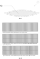
- Fig. 4 presents a part of the photovoltaic lamella coated with the photovoltaic layer according to the invention.
- photovoltaic lamellae were made of aluminium, for example, in the form of a closed aluminium profile with a lens cross-section.
- the closed profile is hollow, such that electric wires (10) may be hidden inside the profile.
- the photovoltaic layer (3) has been attached to one side of the lamella, using double-sided adhesive tape.
- Adhesive tape (4) was placed on the surface of the aluminium layer (5) used to make the lamella, and a single opening (9) was made in the aluminium layer (5) and the adhesive tape (4), passing through said layers, enabling electric wires (10) to be routed to the busbars (7a, 7b).
- a photovoltaic layer (3) is present on the adhesive tape (4), comprised of four connected photovoltaic modules with the dimensions of 10x20 cm.
- the photovoltaic layer (3) is coated with another adhesive layer (2) in the form of a double-sided tape, thanks to which the transparent protective layer (1) was attached to the photovoltaic layer (3). As shown in Fig.
- photovoltaic lamellae were connected to a battery and a power inverter to supply the motor moving the lamellae.
- the module connection method according to the invention a uniform, flat connection between the photovoltaic layer and the lamella is achieved. Thanks to this solution, the lamella production process is also simplified, as it does not require multiple openings to be made in the lamella (lamella profile), as a single opening is enough for routing the electric wires.
- the photovoltaic layer additionally retains integrity thanks to the adhesive used to join the photovoltaic layer with the lamella and with the protective layer.
- FIG. 8-12 Other embodiments of the invention are presented in Fig. 8-12 .
- Fig. 8 presents an example lamella with a depression (11) in the profile, intended for placing a photovoltaic module in it.
- the special depression (11) in the lamella profile was designed such that it enables photovoltaic modules to be placed in the depression in such a way that the total thickness of the modules is generally equal to the depression depth.
- This solution ensures protection against scratching of the film surface and possible peeling of the photovoltaic module from the lamella, prevents water accumulation at the edges, at the same time providing an aesthetic effect, as the entire photovoltaic module is hidden within the depression.
- Fig. 9 presents an example lamella containing insulating material inside.
- the hollow lamella may be used to place insulation material inside, completely filling the inside of the lamella.
- Brise 140 systems with a filling may act as a building insulation with the lamellae in their closed position. Insulation materials providing thermal insulation, soundproofing or electromagnetic insulation may be used in this case.
- Photovoltaic modules may also be connected such that they can operate independently.
- Fig. 10 presents an example layout of photovoltaic modules on the surface of the lamella.
- Fig. 10a presents the photovoltaic modules placed along the entire lamella surface.
- Fig. 10b presents the photovoltaic modules placed on the top and on the bottom surface of the lamella, which operate independently.
- Fig. 10c shows the photovoltaic modules divided along the longer and the shorter edge of the lamella.
- connections according to Fig. 10b ensure that modules remaining in the shade have no negative impact on the operation of the other modules.
- the top or the bottom part of the lamella may be shaded. Such shading may be caused directly by the lamella located above. It is thus preferred for modules present on the top part of the lamella to operate independently of modules located on the bottom part of the lamella.
- connection according to Fig. 10c may be used, where several modules are present on the top or on the bottom part of the lamella, operating independently.
- the division of photovoltaic modules on a single lamella increases operational efficiency of the device and ensures more flexible use, adapted to the specific working conditions of the device.
- Modules located on the top of the lamella are electrically connected together in a series or in parallel, depending on the current and voltage required. This system forms the first section.
- the second section is electrically connected in the same way as the first section, but includes only modules located at the bottom of the lamella.
- two independent sections are obtained which may be connected to the same load using a "bypass diode". They can also be connected independently, to two independent loading channels.
- Two sections shall be present, similar to the configuration according to Fig. 10b .
- the exception is that individual modules on the top and on the bottom part of the lamella are not electrically connected.
- the modules may be produced during a single process. It is possible to produce modules with such dimensions that the modules cover the entire surface area of the lamella, depending on the configuration ( Fig. 10a, b, c ).
- the single stage module production process makes production significantly shorter, and the subsequent installation on the lamella is also shorter.
- Lamellae according to the invention may also include various additives within the adhesive layer.
- Fig. 11 presents an example lamella, in which the adhesive layer (4) contains a reflecting element.
- the adhesive layer (4) located below the photovoltaic layer (3) contains a reflecting element enabling the operational efficiency of the photovoltaic module to be improved.
- Light, which is not initially absorbed by the photovoltaic layer shall be reflected by the reflecting element and shall return to the photovoltaic layer, where it is absorbed and used.
- the reflecting element for example in the form of a reflecting coating, may also be applied onto the layer of the material (5) the lamella is made of.
- the reflecting layer may be made of metals, metal oxides or other materials ensuring formation of a reflecting coating.
- Fig. 12 presents an example lamella, in which the adhesive layer contains a pigment.
- the top adhesive layer (2) contains a pigment, which improves aesthetic properties of the given system and enables colour selection for the specific project.
- the bottom adhesive layer (4) forms a continuous substrate, on which individual modules are placed. Pigment ensuring the impression of continuity may be present in this layer, such that gaps between individual modules are not visible.
Landscapes
- Engineering & Computer Science (AREA)
- Architecture (AREA)
- Civil Engineering (AREA)
- Structural Engineering (AREA)
- Photovoltaic Devices (AREA)
- Organic Low-Molecular-Weight Compounds And Preparation Thereof (AREA)
- Heterocyclic Carbon Compounds Containing A Hetero Ring Having Oxygen Or Sulfur (AREA)
Applications Claiming Priority (3)
| Application Number | Priority Date | Filing Date | Title |
|---|---|---|---|
| PL435260A PL435260A1 (pl) | 2020-09-10 | 2020-09-10 | Lamela fotowoltaiczna, sposób jej wytwarzania oraz łamacz światła zawierający wymienioną lamelę fotowoltaiczną |
| EP21799096.9A EP4222856B1 (de) | 2020-09-10 | 2021-09-10 | Fotovoltaische lamelle, herstellungsverfahren dafür und grisesohle mit der fotovoltaischen lamelle |
| PCT/IB2021/058264 WO2022054004A1 (en) | 2020-09-10 | 2021-09-10 | A photovoltaic lamella, its production method and a brise soleil containing said photovoltaic lamella |
Related Parent Applications (1)
| Application Number | Title | Priority Date | Filing Date |
|---|---|---|---|
| EP21799096.9A Division EP4222856B1 (de) | 2020-09-10 | 2021-09-10 | Fotovoltaische lamelle, herstellungsverfahren dafür und grisesohle mit der fotovoltaischen lamelle |
Publications (3)
| Publication Number | Publication Date |
|---|---|
| EP4422067A2 true EP4422067A2 (de) | 2024-08-28 |
| EP4422067A3 EP4422067A3 (de) | 2024-11-20 |
| EP4422067B1 EP4422067B1 (de) | 2026-03-04 |
Family
ID=80629060
Family Applications (2)
| Application Number | Title | Priority Date | Filing Date |
|---|---|---|---|
| EP24169344.9A Active EP4422067B1 (de) | 2020-09-10 | 2021-09-10 | Fotovoltaische lamelle, herstellungsverfahren dafür und grisesohle mit der fotovoltaischen lamelle |
| EP21799096.9A Active EP4222856B1 (de) | 2020-09-10 | 2021-09-10 | Fotovoltaische lamelle, herstellungsverfahren dafür und grisesohle mit der fotovoltaischen lamelle |
Family Applications After (1)
| Application Number | Title | Priority Date | Filing Date |
|---|---|---|---|
| EP21799096.9A Active EP4222856B1 (de) | 2020-09-10 | 2021-09-10 | Fotovoltaische lamelle, herstellungsverfahren dafür und grisesohle mit der fotovoltaischen lamelle |
Country Status (4)
| Country | Link |
|---|---|
| EP (2) | EP4422067B1 (de) |
| IL (1) | IL301251A (de) |
| PL (2) | PL435260A1 (de) |
| WO (1) | WO2022054004A1 (de) |
Citations (11)
| Publication number | Priority date | Publication date | Assignee | Title |
|---|---|---|---|---|
| WO2007053306A2 (en) | 2005-10-28 | 2007-05-10 | General Electric Company | Photovoltaic modules and interconnect methodology for fabricating the same |
| WO2018049478A1 (en) | 2016-09-15 | 2018-03-22 | Mark Lyons | A modular photovoltaic louvered device |
| US20180195766A1 (en) | 2017-01-11 | 2018-07-12 | Lg Electronics Inc. | Window blind |
| KR20180131751A (ko) | 2017-06-01 | 2018-12-11 | (주)엘지하우시스 | 전극 연결용 커넥터 조립체 및 이를 포함하는 블라인드 날개 |
| KR20180131748A (ko) | 2017-06-01 | 2018-12-11 | (주)엘지하우시스 | 태양광 발전용 블라인드 날개 조립체 및 이를 포함하는 블라인드 |
| EP3441555A1 (de) | 2016-04-06 | 2019-02-13 | Solegrid Inc. | Nachführungsjalousievorrichtung mit solarmodulen |
| KR102078548B1 (ko) | 2018-09-18 | 2020-02-18 | 박종선 | 모듈형 차광 블레이드부를 갖는 자가 발전형 블라인드 |
| EP3633134A1 (de) | 2017-06-01 | 2020-04-08 | LG Hausys, Ltd. | Fotovoltaische lamellenanordnung für jalousie |
| EP3633133A1 (de) | 2017-06-01 | 2020-04-08 | LG Hausys, Ltd. | Photovoltaikjalousie |
| EP3652790A1 (de) | 2017-07-14 | 2020-05-20 | Commonwealth Scientific and Industrial Research Organisation | Photovoltaikvorrichtung und -verfahren |
| CN111395931A (zh) | 2020-04-15 | 2020-07-10 | 华东建筑设计研究院有限公司 | 一种光伏遮阳装置及其控制方法 |
Family Cites Families (6)
| Publication number | Priority date | Publication date | Assignee | Title |
|---|---|---|---|---|
| PL179933B1 (pl) * | 1995-05-30 | 2000-11-30 | Alu Pv As | Uklad ogniwa slonecznego PL |
| DE202004014182U1 (de) * | 2004-09-07 | 2005-01-05 | Bader, Friedrich | Lamelle zur Regulierung des Lichteinfalls in ein Gebäude |
| DE102008014561A1 (de) * | 2008-03-15 | 2009-09-24 | Hydro Aluminium As | Anschlusselement zur Befestigung und/oder Kontaktierung eines elektronischen Moduls |
| WO2011070501A2 (en) * | 2009-12-11 | 2011-06-16 | Plastrim Investments Cc | A window blind of the plantation type |
| US20190259892A1 (en) * | 2017-07-05 | 2019-08-22 | Sigmagen, Inc. | Gravity-Oriented and Vertically-Oriented High-Power-Density Slatted Bifacial Agile Smart Power Generators |
| KR101958432B1 (ko) * | 2018-10-31 | 2019-07-04 | (주)에스케이솔라에너지 | 바이패스 다이오드가 구비된 고효율 태양광 발전용 루버 시스템 |
-
2020
- 2020-09-10 PL PL435260A patent/PL435260A1/pl unknown
-
2021
- 2021-09-10 WO PCT/IB2021/058264 patent/WO2022054004A1/en not_active Ceased
- 2021-09-10 EP EP24169344.9A patent/EP4422067B1/de active Active
- 2021-09-10 PL PL21799096.9T patent/PL4222856T3/pl unknown
- 2021-09-10 EP EP21799096.9A patent/EP4222856B1/de active Active
- 2021-09-10 IL IL301251A patent/IL301251A/en unknown
Patent Citations (11)
| Publication number | Priority date | Publication date | Assignee | Title |
|---|---|---|---|---|
| WO2007053306A2 (en) | 2005-10-28 | 2007-05-10 | General Electric Company | Photovoltaic modules and interconnect methodology for fabricating the same |
| EP3441555A1 (de) | 2016-04-06 | 2019-02-13 | Solegrid Inc. | Nachführungsjalousievorrichtung mit solarmodulen |
| WO2018049478A1 (en) | 2016-09-15 | 2018-03-22 | Mark Lyons | A modular photovoltaic louvered device |
| US20180195766A1 (en) | 2017-01-11 | 2018-07-12 | Lg Electronics Inc. | Window blind |
| KR20180131751A (ko) | 2017-06-01 | 2018-12-11 | (주)엘지하우시스 | 전극 연결용 커넥터 조립체 및 이를 포함하는 블라인드 날개 |
| KR20180131748A (ko) | 2017-06-01 | 2018-12-11 | (주)엘지하우시스 | 태양광 발전용 블라인드 날개 조립체 및 이를 포함하는 블라인드 |
| EP3633134A1 (de) | 2017-06-01 | 2020-04-08 | LG Hausys, Ltd. | Fotovoltaische lamellenanordnung für jalousie |
| EP3633133A1 (de) | 2017-06-01 | 2020-04-08 | LG Hausys, Ltd. | Photovoltaikjalousie |
| EP3652790A1 (de) | 2017-07-14 | 2020-05-20 | Commonwealth Scientific and Industrial Research Organisation | Photovoltaikvorrichtung und -verfahren |
| KR102078548B1 (ko) | 2018-09-18 | 2020-02-18 | 박종선 | 모듈형 차광 블레이드부를 갖는 자가 발전형 블라인드 |
| CN111395931A (zh) | 2020-04-15 | 2020-07-10 | 华东建筑设计研究院有限公司 | 一种光伏遮阳装置及其控制方法 |
Also Published As
| Publication number | Publication date |
|---|---|
| EP4222856B1 (de) | 2024-04-10 |
| PL435260A1 (pl) | 2022-03-14 |
| EP4222856A1 (de) | 2023-08-09 |
| EP4422067B1 (de) | 2026-03-04 |
| EP4222856C0 (de) | 2024-04-10 |
| WO2022054004A1 (en) | 2022-03-17 |
| IL301251A (en) | 2023-05-01 |
| EP4422067A3 (de) | 2024-11-20 |
| PL4222856T3 (pl) | 2024-06-24 |
Similar Documents
| Publication | Publication Date | Title |
|---|---|---|
| Roberts et al. | Building integrated photovoltaics: a handbook | |
| JP6526068B2 (ja) | スケーラブルなサイズ及び電力容量を有する太陽光発電装置 | |
| EP3868018B1 (de) | Gebäudeintegrierte fotovoltaische vorrichtung, insbesondere für fenster und dergleichen, verfahren und lamelle für diese vorrichtung | |
| JP2023029963A (ja) | 窓一体型透明光起電力モジュール | |
| Alhammadi et al. | Building-integrated photovoltaics in hot climates: Experimental study of CIGS and c-Si modules in BIPV ventilated facades | |
| EP1644759B1 (de) | Konzentrations-sonnenkollektor- und -tageslichtlenksystem in verglasten gebäudehüllen | |
| Benson et al. | Design goals and challenges for a photovoltaic-powered electrochromic window covering | |
| US20120118359A1 (en) | Insulating glass composite comprising diagonally arranged photovoltaic cells, and method for the production and use thereof | |
| AU723080B2 (en) | Solar cell system and method of establishing the system | |
| WO2015172054A1 (en) | System and method of rooftop solar energy production | |
| CN201122603Y (zh) | 透光型双层玻璃太阳能电池组件 | |
| US20230019165A1 (en) | Solar panel window shade device and system | |
| KR20220021199A (ko) | 블라인드 타입의 태양광 발전 장치 | |
| US20210152118A1 (en) | Window mounted photovoltaic system with brackets | |
| JP2022526774A (ja) | ブラインド太陽光発電羽根 | |
| KR101935812B1 (ko) | Bipv 창호 시스템 | |
| CN201159021Y (zh) | 一种太阳能光伏电池中空玻璃组件 | |
| EP4222856B1 (de) | Fotovoltaische lamelle, herstellungsverfahren dafür und grisesohle mit der fotovoltaischen lamelle | |
| KR20130115699A (ko) | 태양광전지판을 이용한 엘이디 블라인드장치 | |
| US10665741B2 (en) | Window insulating and power generation system | |
| EP2626649A1 (de) | Blenden mit angeordneten Solarmodulen und unabhängig gesteuerten Zwischenblenden | |
| Osman et al. | Comparative studies on integration of photovoltaic in hot and cold climate | |
| AU2015101750A4 (en) | Solar shutters | |
| US20210152117A1 (en) | Window mounted photovoltaic system | |
| Corkish et al. | Integrated solar photovoltaics for buildings |
Legal Events
| Date | Code | Title | Description |
|---|---|---|---|
| PUAI | Public reference made under article 153(3) epc to a published international application that has entered the european phase |
Free format text: ORIGINAL CODE: 0009012 |
|
| STAA | Information on the status of an ep patent application or granted ep patent |
Free format text: STATUS: THE APPLICATION HAS BEEN PUBLISHED |
|
| AC | Divisional application: reference to earlier application |
Ref document number: 4222856 Country of ref document: EP Kind code of ref document: P |
|
| AK | Designated contracting states |
Kind code of ref document: A2 Designated state(s): AL AT BE BG CH CY CZ DE DK EE ES FI FR GB GR HR HU IE IS IT LI LT LU LV MC MK MT NL NO PL PT RO RS SE SI SK SM TR |
|
| REG | Reference to a national code |
Ref country code: DE Ref legal event code: R079 Free format text: PREVIOUS MAIN CLASS: H02S0020300000 Ref country code: DE Ref legal event code: R079 Ref document number: 602021049562 Country of ref document: DE Free format text: PREVIOUS MAIN CLASS: H02S0020300000 Ipc: H02S0020260000 |
|
| PUAL | Search report despatched |
Free format text: ORIGINAL CODE: 0009013 |
|
| AK | Designated contracting states |
Kind code of ref document: A3 Designated state(s): AL AT BE BG CH CY CZ DE DK EE ES FI FR GB GR HR HU IE IS IT LI LT LU LV MC MK MT NL NO PL PT RO RS SE SI SK SM TR |
|
| RIC1 | Information provided on ipc code assigned before grant |
Ipc: H02S 20/30 20140101ALI20241011BHEP Ipc: H02S 20/26 20140101AFI20241011BHEP |
|
| STAA | Information on the status of an ep patent application or granted ep patent |
Free format text: STATUS: REQUEST FOR EXAMINATION WAS MADE |
|
| 17P | Request for examination filed |
Effective date: 20250518 |
|
| GRAP | Despatch of communication of intention to grant a patent |
Free format text: ORIGINAL CODE: EPIDOSNIGR1 |
|
| STAA | Information on the status of an ep patent application or granted ep patent |
Free format text: STATUS: GRANT OF PATENT IS INTENDED |
|
| INTG | Intention to grant announced |
Effective date: 20250926 |
|
| GRAS | Grant fee paid |
Free format text: ORIGINAL CODE: EPIDOSNIGR3 |
|
| GRAA | (expected) grant |
Free format text: ORIGINAL CODE: 0009210 |
|
| STAA | Information on the status of an ep patent application or granted ep patent |
Free format text: STATUS: THE PATENT HAS BEEN GRANTED |
|
| AC | Divisional application: reference to earlier application |
Ref document number: 4222856 Country of ref document: EP Kind code of ref document: P |
|
| AK | Designated contracting states |
Kind code of ref document: B1 Designated state(s): AL AT BE BG CH CY CZ DE DK EE ES FI FR GB GR HR HU IE IS IT LI LT LU LV MC MK MT NL NO PL PT RO RS SE SI SK SM TR |
|
| REG | Reference to a national code |
Ref country code: CH Ref legal event code: F10 Free format text: ST27 STATUS EVENT CODE: U-0-0-F10-F00 (AS PROVIDED BY THE NATIONAL OFFICE) Effective date: 20260304 Ref country code: GB Ref legal event code: FG4D |
|
| REG | Reference to a national code |
Ref country code: IE Ref legal event code: FG4D |
|
| REG | Reference to a national code |
Ref country code: DE Ref legal event code: R096 Ref document number: 602021049562 Country of ref document: DE |