EP4422035A1 - Rotor, rotating electric machine, and electric power steering device - Google Patents
Rotor, rotating electric machine, and electric power steering device Download PDFInfo
- Publication number
- EP4422035A1 EP4422035A1 EP21961374.2A EP21961374A EP4422035A1 EP 4422035 A1 EP4422035 A1 EP 4422035A1 EP 21961374 A EP21961374 A EP 21961374A EP 4422035 A1 EP4422035 A1 EP 4422035A1
- Authority
- EP
- European Patent Office
- Prior art keywords
- magnets
- rotor
- rotor core
- magnet
- protrusion
- Prior art date
- Legal status (The legal status is an assumption and is not a legal conclusion. Google has not performed a legal analysis and makes no representation as to the accuracy of the status listed.)
- Pending
Links
Images


Classifications
-
- H—ELECTRICITY
- H02—GENERATION; CONVERSION OR DISTRIBUTION OF ELECTRIC POWER
- H02K—DYNAMO-ELECTRIC MACHINES
- H02K1/00—Details of the magnetic circuit
- H02K1/06—Details of the magnetic circuit characterised by the shape, form or construction
- H02K1/22—Rotating parts of the magnetic circuit
- H02K1/27—Rotor cores with permanent magnets
- H02K1/2706—Inner rotors
- H02K1/272—Inner rotors the magnetisation axis of the magnets being perpendicular to the rotor axis
- H02K1/274—Inner rotors the magnetisation axis of the magnets being perpendicular to the rotor axis the rotor consisting of two or more circumferentially positioned magnets
- H02K1/2753—Inner rotors the magnetisation axis of the magnets being perpendicular to the rotor axis the rotor consisting of two or more circumferentially positioned magnets the rotor consisting of magnets or groups of magnets arranged with alternating polarity
- H02K1/278—Surface mounted magnets; Inset magnets
-
- H—ELECTRICITY
- H02—GENERATION; CONVERSION OR DISTRIBUTION OF ELECTRIC POWER
- H02K—DYNAMO-ELECTRIC MACHINES
- H02K16/00—Machines with more than one rotor or stator
- H02K16/02—Machines with one stator and two or more rotors
-
- H—ELECTRICITY
- H02—GENERATION; CONVERSION OR DISTRIBUTION OF ELECTRIC POWER
- H02K—DYNAMO-ELECTRIC MACHINES
- H02K21/00—Synchronous motors having permanent magnets; Synchronous generators having permanent magnets
- H02K21/12—Synchronous motors having permanent magnets; Synchronous generators having permanent magnets with stationary armatures and rotating magnets
- H02K21/14—Synchronous motors having permanent magnets; Synchronous generators having permanent magnets with stationary armatures and rotating magnets with magnets rotating within the armatures
-
- B—PERFORMING OPERATIONS; TRANSPORTING
- B62—LAND VEHICLES FOR TRAVELLING OTHERWISE THAN ON RAILS
- B62D—MOTOR VEHICLES; TRAILERS
- B62D5/00—Power-assisted or power-driven steering
- B62D5/04—Power-assisted or power-driven steering electrical, e.g. using an electric servo-motor connected to, or forming part of, the steering gear
-
- H—ELECTRICITY
- H02—GENERATION; CONVERSION OR DISTRIBUTION OF ELECTRIC POWER
- H02K—DYNAMO-ELECTRIC MACHINES
- H02K2201/00—Specific aspects not provided for in the other groups of this subclass relating to the magnetic circuits
- H02K2201/06—Magnetic cores, or permanent magnets characterised by their skew
-
- H—ELECTRICITY
- H02—GENERATION; CONVERSION OR DISTRIBUTION OF ELECTRIC POWER
- H02K—DYNAMO-ELECTRIC MACHINES
- H02K2213/00—Specific aspects, not otherwise provided for and not covered by codes H02K2201/00 - H02K2211/00
- H02K2213/03—Machines characterised by numerical values, ranges, mathematical expressions or similar information
-
- H—ELECTRICITY
- H02—GENERATION; CONVERSION OR DISTRIBUTION OF ELECTRIC POWER
- H02K—DYNAMO-ELECTRIC MACHINES
- H02K29/00—Motors or generators having non-mechanical commutating devices, e.g. discharge tubes or semiconductor devices
- H02K29/03—Motors or generators having non-mechanical commutating devices, e.g. discharge tubes or semiconductor devices with a magnetic circuit specially adapted for avoiding torque ripples or self-starting problems
Definitions
- the present disclosure relates to a rotor, a rotating electric machine, and an electric power steering device.
- the rotating electric machine of Patent Document 1 includes a rotor and a stator.
- the rotor has a first rotor core, a second rotor core, and a plurality of magnets that are aligned and disposed on an outer circumferential surface of each rotor core.
- Locations of magnets of the first rotor core (herein referred to as a "first magnet”) and magnets of the second rotor core (herein referred to as a "second magnet”) are offset in the circumferential direction.
- adopting what is known as a "step skew construction" of the rotors is known to reduce torque ripple.
- Patent Document 1 Japanese Patent No. 5720939
- a first magnet and a second magnet when a first magnet and a second magnet come into contact, magnets of differing polarities come into contact with one another.
- magnets of differing polarities When magnets of differing polarities come into contact with one another, magnetic flux leakage at the location of contact becomes large, increasing torque ripple and so forth, which is connected to a decrease in performance of the rotating electric machine. Therefore, it is preferable that the first magnet and the second magnet are disposed so as not to come into contact with one another.
- the inventors of the present disclosure have found that making a distance between the first magnet and the second magnet too large leads to a decrease in performance of the rotating electric machine.
- the present disclosure has been made in order to address the problem above, and an object is to avoid a decrease in performance of a rotating electric machine by optimizing a distance between a first magnet and a second magnet.
- a rotor includes: a shaft; a first rotor core and a second rotor core that are fixed to the shaft, and that are disposed so as to align in an axial direction along a center axis of the shaft; a plurality of first magnets that are disposed so as to align in a circumferential direction which revolves around the center axis on an outer circumferential surface of the first rotor core, and a plurality of second magnets that are disposed so as to align in the circumferential direction on the outer circumferential surface of the second rotor core, wherein locations of the plurality of first magnets and the plurality of second magnets are offset in the circumferential direction, and an interval between the plurality of first magnets and the plurality of second magnets in the axial direction is within a range of 0.5 to 3.0mm.
- a rotating electric machine may include the rotor, and the stator that surrounds the rotor.
- An electric power steering device may include the rotating electric machine mentioned above.
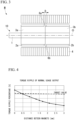
- FIG. 1 is a perspective view of a rotor 10 in a first embodiment.
- FIG. 2 is an exploded view of FIG. 1 .
- FIG. 3 is a cross-sectional view of a rotating electric machine M that includes the rotor 10 shown in FIG. 1 .
- the rotating electric machine M is for example, used as a motor of an electric power steering device of a vehicle.
- the rotating electric machine M has the rotor 10 and a stator 4.
- the rotor 10 has a shaft 1, a first rotor core 3a, a second rotor core 3b, a plurality of first magnets 2a, and a plurality of second magnets 2b.
- the stator 4 is disposed so as to surround a first magnet 2a and a second magnet 2b.
- a vehicle steering apparatus that includes the electric power steering device is connected to the shaft 1.
- a direction along a center axis O of the shaft 1 is referred to as an "axial direction”.
- a direction that intersects with the center axis O, as seen from the axial direction, is referred to as a "radial direction”.
- a direction which revolves around the center axis O is referred to as a "circumferential direction”.
- the first rotor core 3a and the second rotor core 3b are fixed to the shaft 1.
- the first rotor core 3a and the second rotor core 3b are disposed so as to align in the axial direction, in a state of being in contact with one another.
- the first rotor core 3a and the second rotor core 3b are for example formed by stacking a plurality of core pieces.
- a core piece for example, is formed by press working a sheet of low-carbon steel. Materials and methods of forming the first rotor core 3a and the second rotor core 3b are not limited to the above, and may be changed accordingly.
- the plurality of first magnets 2a are disposed so as to align equidistantly in the circumferential direction, on an outer circumferential surface of the first rotor core 3a.
- the plurality of second magnet 2b are disposed so as to align equidistantly in the circumferential direction, on an outer circumferential surface of the second rotor core 3b.
- a polarity of each of first magnets 2a mutually interchanges in the circumferential direction.
- a polarity of each of second magnets 2b mutually interchanges in the circumferential direction.
- magnets 2a and 2b it is possible to use niobium magnets. Materials of magnets 2a, 2b may also be changed accordingly.
- the rotor 10 adopts the so-called step skew construction. Specifically, locations in the circumferential direction of the plurality of first magnets 2a and the plurality of second magnets 2b are offset from one another. As such, when attention is given to an arbitrary first magnet 2a, the arbitrary first magnet 2a is adjacent to two second magnets 2b in the axial direction. Polarities of the two second magnet 2b are different from one another. Therefore, one of the two second magnet 2b has a different polarity than the first magnet 2a adjacent thereto in the in the axial direction.
- a plurality of slots are provided so as to protrude to an inside in the radial direction of the stator 4.
- Each slot is disposed so as to align in the circumferential direction.
- the rotating electric machine M is a so-called eight-pole/twelve-slot motor.
- a number of each of the first magnet 2a and the second magnet 2b is eight, and a number of slots that the stator 4 has is twelve. Numbers of the first magnet 2a, the second magnet 2b, and the slots may be changed accordingly.
- the rotor 10 may also have three or more slot cores.
- a length of the first rotor core 3a is longer than a length of the first magnet 2a in the axial direction.
- a length of the second rotor core 3b is preferable for a length of the second magnet 2b in the axial direction.
- a magnetic flux that is comes out of the magnets 2a, 2b passes through rotor cores 3a, 3b after passing through the stator 4, and returns to the magnets 2a, 2b.
- Magnetic flux leakage is a phenomenon that occurs when a magnetic flux coming out of a magnet does not pass through a conventional path (a path that goes through the stator, the rotor core and such), and thus does not contribute to torque generation of the rotating electric machine M.
- the plurality of first magnets 2a and the plurality of second magnet 2b be separated in the axial direction. As shown in FIG. 3 , a distance between the first magnet 2a and the second magnet 2b in the axial direction referred to as a "distance between magnets D" in the present description is shown.
- FIG. 4 and FIG. 5 are used to explain the aforementioned in more detail.
- FIG. 4 is a graph that shows a relationship between the torque ripple and the distance between magnets D, in a case of normal usage output of the rotating electric machine M used in the electric power steering device.
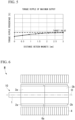
- FIG. 5 is a graph that shows a relationship between the torque ripple in the case of maximum output and the distance between magnets D of the rotating electric machine M similar to that of FIG. 4 .
- the horizontal axis in FIG. 4 and FIG. 5 is the distance between magnets D, expressed in units of mm, and the vertical axis in FIG. 4 and FIG. 5 is a torque ripple percentage.
- the torque ripple percentage is a value of variability in an average value of the torque, shown as a percentile (%) amount.
- a first rotor core 3a is provided in a first protrusion 6a
- the second rotor core 3b is provided in a second protrusion 6b (refer to FIG. 2 and FIG. 3 ).
- the first protrusion 6a protrudes outwards in the radial direction from the outer circumferential surface of the first rotor core 3a.
- the first protrusion 6a is disposed in a location that contacts the second rotor core 3b in the axial direction.
- the first protrusion 6a is disposed between two of the first magnets 2a that are adjacent in the circumferential direction.
- the second protrusion 6b protrudes outwards in the radial direction from the outer circumferential surface of the second rotor core 3b.
- the second protrusion 6b is disposed in a location that contacts the first rotor core 3a in the axial direction.
- the second protrusion 6b is disposed between two of the second magnets 2b that are adjacent in the circumferential direction.
- the rotor 10 when attaching the first magnet 2a to the first rotor core 3a, by making a location of the first protrusion 6a be a reference point, aligning a location of the first magnet 2a in the axial direction to a predetermined location becomes easy.
- the second magnet 2b when attaching the second magnet 2b to the second rotor core 3b, by making a location of the second protrusion 6b be a reference point, aligning a location of the second magnet 2b in the axial direction to a predetermined location becomes easy.
- a predetermined location is a location of the first magnet 2a and the second magnet 2b, where the distance between magnets D is greater than or equal to 0.5mm, and less than or equal to 3.0mm.
- protrusions 6a, 6b it becomes easy to adjust the distance between magnets D so as to be in the range of greater than or equal to 0.5mm and less than or equal to 3.0mm. Accordingly, it is possible to have the torque ripple percentage of both the normal usage output and the maximum output cases be within the range of the target value. Further, it is possible, in advance, to form parts that are to become first protrusions 6a and second protrusions 6b in parts that are to become first rotor cores 3a and second rotor cores 3b. Accordingly, adjusting the distance between magnets D without increasing a number of parts is possible.
- locations in the axial direction of the protrusions 6a, 6b are used as reference points when attaching the magnets 2a, 2b to the rotor cores 3a, 3b.
- the protrusions 6a, 6b need not be disposed in a vicinity of a surface where the rotor cores 3a, 3b contact one another.
- the first protrusion 6a may be disposed in a center portion of the first rotor core 3a in the axial direction.
- the second protrusion 6b may be disposed in a center portion of the second rotor core 3b in the axial direction.
- the first protrusion 6a does not have to be formed in the first rotor core 3a
- the second protrusion 6b does not have to be formed in the second rotor core 3b.
- the first protrusion 6a it is possible to at least use the first protrusion 6a as a location reference point in the axial direction when attaching the first magnet 2a to the first rotor core 3a, making it easy to have the distance between magnets D be within the predetermined range.
- the second protrusion 6b may be formed in the second rotor core 3b
- the first protrusion 6a may be formed in the first rotor core 3a.
- the first protrusion 6a is formed over an entire circumference of the outer circumferential surface of the first rotor core 3a.
- the second protrusion 6b is formed over an entire circumference of the outer circumferential surface of the second rotor core 3b.
- the first protrusion 6a and the second protrusion 6b are annular, as seen from the axial direction. The first protrusion 6a and the second protrusion 6b are also in contact with one another.
- the present embodiment it is possible to avoid having the first magnet 2a and the second magnet 2b contact one another using the first protrusion 6a and the second protrusion 6b.
- the first protrusion 6a and the second protrusion 6b as a spacer.
- the sum of thicknesses of the first protrusion 6a and the second protrusion 6b in the axial direction become the distance between magnets D. Therefore, having the distance between magnets D be within a predetermined value range becomes easier.
- the sum of thicknesses of the first protrusion 6a and the second protrusion 6b in the axial direction may be within the range of 0.5 to 3.0mm.
- annular protrusion may be formed in only one rotor core out of the first rotor core 3a and the second rotor core 3b.
- the annular first protrusion 6a is formed in the first rotor core 3a, and no annular protrusion is formed in the second rotor core 3b. Even in such case, it is possible to avoid having the first magnet 2a and the second magnet 2b contact one another by the existence of the first protrusion 6a. Both the first magnet 2a and the second magnet 2b may contact the first protrusion 6a. In such case, the thickness of the first protrusion 6a in the axial direction is the distance between magnets D.
- the thickness of the first protrusion 6a may be within the range of 0.5 to 3.0mm.
- the annular protrusion second protrusion 6b may only be formed in the second rotor core 3b, and the thickness of the second protrusion 6b may be within the range of 0.5 to 3.0mm.
- the protrusions 6a, 6b need not be annular, as seen from the axial direction.
- a plurality of first protrusions 6a may be disposed intermittently in the circumferential direction, and each of the first protrusions 6a may be located between the first magnet 2a and the second magnet 2b in the axial direction. Even in such case, each of the first protrusions 6a functions as a spacer to secure a gap between the first magnet 2a and the second magnet 2b.
- a plurality of second protrusions 6b may be disposed intermittently in the circumferential direction, and each of the second protrusions 6b may be located between the first magnet 2a and the second magnet 2b in the axial direction.
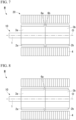
- the protrusions 6a, 6b are not formed in the rotor cores 3a, 3b, and a gap 5 between the first magnet 2a and the second magnet 2b is formed.
- a dimension of the gap 5 in the axial direction becomes the distance between magnets D. Therefore, by setting the dimension of the gap 5 in the axial direction to the range of 0.5 to 3.0mm, the same effects as those mentioned in the first embodiment are obtainable.
- first extension 7a in the first magnet 2a is a portion that extends outwards in the axial direction from a first end surface 4a of the stator 4, out of the first magnet 2a.
- second extension 7b on the second magnet 2b is a portion that extends outwards in the axial direction from a second end surface 4b of the stator 4, out of the second magnet 2b.
- the first rotor core 3a extends outwards in the axial direction from the first end surface 4a of the stator 4.
- the second rotor core 3b extends outwards in the axial direction from the second end surface 4b of the stator 4.
- the present embodiment by having the magnetic flux of the magnets 2a, 2b which decreased due to the provision of the gap 5 be compensated by the first extension 7a and the second extension 7b, it is possible to suppress a decrease in the output torque of the rotating electric machine M.
- a length of protrusion of the first extension 7a in the axial direction with respect to the first end surface 4a be within the range of 0.5 to 3.0mm.
- a length of protrusion of the second extension 7b in the axial direction with respect to the second end surface 4b be within the range of 0.5 to 3.0mm.
- An extension may be provided in only one out of the first magnet 2a and the second magnet 2b.
- the first extension 7a may be provided in the first magnet 2a, and the second extension 7b need not be provided in the second magnet 2b. Even in such case, since at least the magnetic flux of the first magnet 2a is compensated for, it is possible to suppress the decrease in the output torque of the rotating electric machine M.
- the second extension 7b may be provided in the second magnet 2b, and the extension may not be provided in the first magnet 2a.
- Both or one of the first extension 7a and the second extension 7b shown in FIG. 10 may be provided in the rotor 10 shown in FIG. 3 , FIG. 6 , FIG. 7, and FIG. 8 .
- a rotor 10 includes the shaft 1, the first rotor core 3a and the second rotor core 3b that are fixed to the shaft 1, and that are disposed so as to align in the axial direction along the center axis O of the shaft 1, the plurality of first magnets 2a that are disposed so as to align in the circumferential direction which revolves around the center axis O on the outer circumferential surface of the first rotor core 3a, and the plurality of second magnets 2b that are disposed so as to align in the circumferential direction on the outer circumferential surface of the second rotor core 3b, wherein the locations of the plurality of first magnets 2a and the plurality of second magnets 2b are offset in the circumferential direction, and an interval between the plurality of first magnets 2a and the plurality of second magnets 2b in the axial direction is within the range of 0.5 to 3.0mm.
- the distance between magnets D be greater than or equal to 0.5mm, it is possible to suppress the torque ripple in the case of normal usage output.
- the distance between magnets D be less than or equal to 3.0mm, it is possible to suppress the torque ripple in the case of maximum output. Accordingly, it is possible to provide a rotor 10 that is capable of decreasing the torque ripple in in both cases of normal usage output and of maximum output.
- the protrusion (the first protrusion 6a or the second protrusion 6b) may be formed on at least one of the first rotor core 3a and the second rotor core 3b, and the protrusion may be located between two of the first magnets 2a adjacent to one another in the circumferential direction, or between two of the second magnets 2b adjacent to one another in the circumferential direction. In such case, it is possible to use the protrusion as the reference point when attaching the first magnet 2a to the first rotor core 3a, or when attaching the second magnet 2b to the second rotor core 3b.
- the protrusion (the first protrusion 6a or the second protrusion 6b) may be formed on at least one of the first rotor core 3a and the second rotor core 3b, and the protrusion may be located between the first magnet 2a and the second magnet 2b that are adjacent to one another in the axial direction. In such case, the protrusion functions as a spacer, and it is possible to avoid having the first magnet 2a come into contact with the second magnet 2b.
- the protrusion may be annular, as seen from the axial direction. In such case, it is possible to easily dispose the protrusion between all of the first magnets 2a and all of the second magnets 2b.
- the protrusions may come into contact with both the first magnet 2a and the second magnet 2b that are adjacent in the axial direction.
- a dimension of the protrusion in the axial direction is the distance between magnets D. Therefore, it is possible to more easily adjust the distance between magnets D within the range of 0.5 to 3.0mm.
- the gap 5 may be provided between the plurality of first magnets 2a and the plurality of second magnets 2b.
- the rotating electric machine M includes the rotor 10, and the stator 4 that surrounds the rotor 10.
- the extension (the first extension 7a or the second extension 7b) that extends from end surfaces of the stator 4 in the axial direction may be formed in at least one of the plurality of first magnets 2a and the plurality of second magnets 2b. In such case, it is possible to compensate the decrease in magnetic flux of the first magnet 2a or the second magnet 2b due to the provision of the distance between magnets D. Therefore, it is possible to suppress the decrease in the output torque of the rotating electric machine M.
- the dimension of the extension in the axial direction may be within the range of 0.5 to 3.0mm. In such case, it is possible to suppress a decrease in effective utilization rate of the magnetic flux of the magnet due to the extension being excessively large.
- An electric power steering device includes the rotating electric machine M mentioned above. According to such electric power steering device, it is possible to achieve comfortable operation during both cases of normal usage output or maximum output.
- the rotating electrical machine M according to the present disclosure may be utilized in a device other than an electric power steering device.
Landscapes
- Engineering & Computer Science (AREA)
- Power Engineering (AREA)
- Permanent Field Magnets Of Synchronous Machinery (AREA)
Abstract
Description
- The present disclosure relates to a rotor, a rotating electric machine, and an electric power steering device.
- The rotating electric machine of
Patent Document 1 includes a rotor and a stator. The rotor has a first rotor core, a second rotor core, and a plurality of magnets that are aligned and disposed on an outer circumferential surface of each rotor core. Locations of magnets of the first rotor core (herein referred to as a "first magnet") and magnets of the second rotor core (herein referred to as a "second magnet") are offset in the circumferential direction. As such, adopting what is known as a "step skew construction" of the rotors is known to reduce torque ripple. - [Patent Document 1]
Japanese Patent No. 5720939 - In a rotor of a step skew construction, when a first magnet and a second magnet come into contact, magnets of differing polarities come into contact with one another. When magnets of differing polarities come into contact with one another, magnetic flux leakage at the location of contact becomes large, increasing torque ripple and so forth, which is connected to a decrease in performance of the rotating electric machine. Therefore, it is preferable that the first magnet and the second magnet are disposed so as not to come into contact with one another. The inventors of the present disclosure have found that making a distance between the first magnet and the second magnet too large leads to a decrease in performance of the rotating electric machine.
- The present disclosure has been made in order to address the problem above, and an object is to avoid a decrease in performance of a rotating electric machine by optimizing a distance between a first magnet and a second magnet.
- A rotor, according to an embodiment of the present disclosure includes: a shaft; a first rotor core and a second rotor core that are fixed to the shaft, and that are disposed so as to align in an axial direction along a center axis of the shaft; a plurality of first magnets that are disposed so as to align in a circumferential direction which revolves around the center axis on an outer circumferential surface of the first rotor core, and a plurality of second magnets that are disposed so as to align in the circumferential direction on the outer circumferential surface of the second rotor core, wherein locations of the plurality of first magnets and the plurality of second magnets are offset in the circumferential direction, and an interval between the plurality of first magnets and the plurality of second magnets in the axial direction is within a range of 0.5 to 3.0mm.
- A rotating electric machine according to an embodiment of the present disclosure may include the rotor, and the stator that surrounds the rotor.
- An electric power steering device according to an embodiment of the present disclosure may include the rotating electric machine mentioned above.
- According to the present disclosure, it is possible to avoid a decrease in performance of a rotating electric machine by optimizing a distance between a first magnet and a second magnet.
-
- [
FIG. 1 ] A perspective view of a rotor according to a first embodiment. - [
FIG. 2 ] An exploded view ofFIG. 1 . - [
FIG. 3 ] A cross-sectional view of a rotating electric machine according to the first embodiment. - [
FIG. 4 ] A graph that shows a relationship between a distance between magnets and a torque ripple percentage, in a case of normal usage output. - [
FIG. 5 ] A graph that shows a relationship between a distance between magnets and a torque ripple percentage, in a case of maximum output. - [
FIG. 6 ] A cross-sectional view of the rotating electric machine according to a modified example of the first embodiment. - [
FIG. 7 ] A cross-sectional view of the rotating electric machine according to a second embodiment. - [
FIG. 8 ] A cross-sectional view of the rotating electric machine according to a modified example of the second embodiment. - [
FIG. 9 ] A cross-sectional view of the rotating electric machine according to a third embodiment. - [
FIG. 10 ] A cross-sectional view of the rotating electric machine according to a modified example of the third embodiment. - Hereinafter, embodiments pertaining of the present disclosure are explained with reference to the drawings. The extent of the present disclosure is not limited to the explanations of the embodiments below, and the embodiments may be changed as long as changes remain within the bounds of the technical scope thereof.
-
FIG. 1 is a perspective view of arotor 10 in a first embodiment.FIG. 2 is an exploded view ofFIG. 1 .FIG. 3 is a cross-sectional view of a rotating electric machine M that includes therotor 10 shown inFIG. 1 . The rotating electric machine M is for example, used as a motor of an electric power steering device of a vehicle. - As shown in
FIG. 3 , the rotating electric machine M has therotor 10 and astator 4. Therotor 10 has ashaft 1, afirst rotor core 3a, asecond rotor core 3b, a plurality offirst magnets 2a, and a plurality ofsecond magnets 2b. Thestator 4 is disposed so as to surround afirst magnet 2a and asecond magnet 2b. A vehicle steering apparatus that includes the electric power steering device is connected to theshaft 1. - In the present embodiment, a direction along a center axis O of the
shaft 1 is referred to as an "axial direction". A direction that intersects with the center axis O, as seen from the axial direction, is referred to as a "radial direction". A direction which revolves around the center axis O is referred to as a "circumferential direction". - The
first rotor core 3a and thesecond rotor core 3b are fixed to theshaft 1. Thefirst rotor core 3a and thesecond rotor core 3b are disposed so as to align in the axial direction, in a state of being in contact with one another. Thefirst rotor core 3a and thesecond rotor core 3b are for example formed by stacking a plurality of core pieces. A core piece, for example, is formed by press working a sheet of low-carbon steel. Materials and methods of forming thefirst rotor core 3a and thesecond rotor core 3b are not limited to the above, and may be changed accordingly. - The plurality of
first magnets 2a are disposed so as to align equidistantly in the circumferential direction, on an outer circumferential surface of thefirst rotor core 3a. The plurality ofsecond magnet 2b are disposed so as to align equidistantly in the circumferential direction, on an outer circumferential surface of thesecond rotor core 3b. A polarity of each offirst magnets 2a mutually interchanges in the circumferential direction. Similarly, a polarity of each ofsecond magnets 2b mutually interchanges in the circumferential direction. As an example ofmagnets magnets - The
rotor 10 according to the present embodiment adopts the so-called step skew construction. Specifically, locations in the circumferential direction of the plurality offirst magnets 2a and the plurality ofsecond magnets 2b are offset from one another. As such, when attention is given to an arbitraryfirst magnet 2a, the arbitraryfirst magnet 2a is adjacent to twosecond magnets 2b in the axial direction. Polarities of the twosecond magnet 2b are different from one another. Therefore, one of the twosecond magnet 2b has a different polarity than thefirst magnet 2a adjacent thereto in the in the axial direction. - Although omitted from the drawings, a plurality of slots are provided so as to protrude to an inside in the radial direction of the
stator 4. Each slot is disposed so as to align in the circumferential direction. The rotating electric machine M according to the present embodiment is a so-called eight-pole/twelve-slot motor. In other words, a number of each of thefirst magnet 2a and thesecond magnet 2b is eight, and a number of slots that thestator 4 has is twelve. Numbers of thefirst magnet 2a, thesecond magnet 2b, and the slots may be changed accordingly. Therotor 10 may also have three or more slot cores. - It is preferable for a length of the
first rotor core 3a to be longer than a length of thefirst magnet 2a in the axial direction. Similarly, it is preferable for a length of thesecond rotor core 3b to be longer than a length of thesecond magnet 2b in the axial direction. Usually, a magnetic flux that is comes out of themagnets rotor cores stator 4, and returns to themagnets rotor cores magnets magnets rotor cores magnets magnets - In the
rotor 10 which adopts the step skew construction as in the present embodiment, even if thefirst magnet 2a and thesecond magnet 2b contact one another in the axial direction, magnets that have differing poles come into contact with one another. When the magnets that have differing poles come into contact with one another, a magnetic flux leakage at a location of contact becomes large, and the torque ripple increases. "Magnetic flux leakage" is a phenomenon that occurs when a magnetic flux coming out of a magnet does not pass through a conventional path (a path that goes through the stator, the rotor core and such), and thus does not contribute to torque generation of the rotating electric machine M. To suppress magnetic flux leakage, it is preferable to have the plurality offirst magnets 2a and the plurality ofsecond magnet 2b be separated in the axial direction. As shown inFIG. 3 , a distance between thefirst magnet 2a and thesecond magnet 2b in the axial direction referred to as a "distance between magnets D" in the present description is shown. - If the distance between magnets D is too large, a volume of the
magnets FIG. 4 andFIG. 5 are used to explain the aforementioned in more detail. -
FIG. 4 is a graph that shows a relationship between the torque ripple and the distance between magnets D, in a case of normal usage output of the rotating electric machine M used in the electric power steering device.FIG. 5 is a graph that shows a relationship between the torque ripple in the case of maximum output and the distance between magnets D of the rotating electric machine M similar to that ofFIG. 4 . The horizontal axis inFIG. 4 andFIG. 5 is the distance between magnets D, expressed in units of mm, and the vertical axis inFIG. 4 andFIG. 5 is a torque ripple percentage. The torque ripple percentage is a value of variability in an average value of the torque, shown as a percentile (%) amount. - As shown in
FIG. 4 , in normal usage output, the bigger the distance between magnets D, the more the torque ripple decreases. As a result of considerations done by the inventors of the present invention, when the distance between magnets D is greater than or equal to 0.5mm, it is possible for the torque ripple percentage to be less than or equal to a target value. - As shown in
FIG. 5 , in maximum output, the bigger the distance between magnets D, the more the torque ripple increases. As a result of considerations done by the inventors of the present invention, when the distance between magnets D is less than or equal to 3.0mm, it is possible for the torque ripple percentage in the case of maximum output to be less than or equal to the target value. - Integrating the results of
FIG. 4 andFIG. 5 , having the distance between magnets D be greater than or equal to 0.5mm, and less than or equal to 3.0mm is preferable. In the present embodiment, to have the distance between magnets D be a value within the range mentioned above, afirst rotor core 3a is provided in afirst protrusion 6a, and thesecond rotor core 3b is provided in asecond protrusion 6b (refer toFIG. 2 andFIG. 3 ). Thefirst protrusion 6a protrudes outwards in the radial direction from the outer circumferential surface of thefirst rotor core 3a. Thefirst protrusion 6a is disposed in a location that contacts thesecond rotor core 3b in the axial direction. Thefirst protrusion 6a is disposed between two of thefirst magnets 2a that are adjacent in the circumferential direction. Thesecond protrusion 6b protrudes outwards in the radial direction from the outer circumferential surface of thesecond rotor core 3b. Thesecond protrusion 6b is disposed in a location that contacts thefirst rotor core 3a in the axial direction. Thesecond protrusion 6b is disposed between two of thesecond magnets 2b that are adjacent in the circumferential direction. - During manufacture the
rotor 10, when attaching thefirst magnet 2a to thefirst rotor core 3a, by making a location of thefirst protrusion 6a be a reference point, aligning a location of thefirst magnet 2a in the axial direction to a predetermined location becomes easy. Similarly, when attaching thesecond magnet 2b to thesecond rotor core 3b, by making a location of thesecond protrusion 6b be a reference point, aligning a location of thesecond magnet 2b in the axial direction to a predetermined location becomes easy. What is referred to as a "predetermined location" above is a location of thefirst magnet 2a and thesecond magnet 2b, where the distance between magnets D is greater than or equal to 0.5mm, and less than or equal to 3.0mm. - As such, by using
protrusions first protrusions 6a andsecond protrusions 6b in parts that are to becomefirst rotor cores 3a andsecond rotor cores 3b. Accordingly, adjusting the distance between magnets D without increasing a number of parts is possible. - In the present embodiment, locations in the axial direction of the
protrusions magnets rotor cores protrusions rotor cores first protrusion 6a may be disposed in a center portion of thefirst rotor core 3a in the axial direction. In such case, if a marking or the like is located in the center portion of thefirst magnet 2a in the axial direction, by adjusting the location of the marking or the like with thefirst protrusion 6a as the reference point, adjustment of thefirst magnet 2a in the axial direction is possible. Similarly, thesecond protrusion 6b may be disposed in a center portion of thesecond rotor core 3b in the axial direction. - As in shown in
FIG. 6 , thefirst protrusion 6a does not have to be formed in thefirst rotor core 3a, and thesecond protrusion 6b does not have to be formed in thesecond rotor core 3b. In such case, it is possible to at least use thefirst protrusion 6a as a location reference point in the axial direction when attaching thefirst magnet 2a to thefirst rotor core 3a, making it easy to have the distance between magnets D be within the predetermined range. Similarly, thesecond protrusion 6b may be formed in thesecond rotor core 3b, and thefirst protrusion 6a may be formed in thefirst rotor core 3a. - Next, a rotating electric machine according to a second embodiment is explained. Since the rotating electric machine according to the present embodiment is similar in construction to the rotating electric machine of the first embodiment, explanations that follow focus mainly on differences therebetween.
- As shown in
FIG. 7 , in the present embodiment, thefirst protrusion 6a is formed over an entire circumference of the outer circumferential surface of thefirst rotor core 3a. Similarly, thesecond protrusion 6b is formed over an entire circumference of the outer circumferential surface of thesecond rotor core 3b. Although omitted from the drawings, thefirst protrusion 6a and thesecond protrusion 6b are annular, as seen from the axial direction. Thefirst protrusion 6a and thesecond protrusion 6b are also in contact with one another. - According to the present embodiment, it is possible to avoid having the
first magnet 2a and thesecond magnet 2b contact one another using thefirst protrusion 6a and thesecond protrusion 6b. In other words, it is possible to use thefirst protrusion 6a and thesecond protrusion 6b as a spacer. During manufacture of therotor 10, it is possible to have thefirst magnet 2a abut against thefirst protrusion 6a, and thesecond magnet 2b abut against thefirst protrusion 6a. In such case, the sum of thicknesses of thefirst protrusion 6a and thesecond protrusion 6b in the axial direction become the distance between magnets D. Therefore, having the distance between magnets D be within a predetermined value range becomes easier. To be more specific, the sum of thicknesses of thefirst protrusion 6a and thesecond protrusion 6b in the axial direction may be within the range of 0.5 to 3.0mm. - It is possible, in advance, to form locations that become the
first protrusion 6a and thesecond protrusion 6b in core pieces that are to become thefirst rotor core 3a and thesecond rotor core 3b. Accordingly, controlling the distance between magnets D without increasing a number of parts is made easy. When stacking the core pieces in the axial direction, two types of core pieces, a first core piece where protrusions that become theprotrusions protrusions - An annular protrusion may be formed in only one rotor core out of the
first rotor core 3a and thesecond rotor core 3b. In the example ofFIG. 8 , the annularfirst protrusion 6a is formed in thefirst rotor core 3a, and no annular protrusion is formed in thesecond rotor core 3b. Even in such case, it is possible to avoid having thefirst magnet 2a and thesecond magnet 2b contact one another by the existence of thefirst protrusion 6a. Both thefirst magnet 2a and thesecond magnet 2b may contact thefirst protrusion 6a. In such case, the thickness of thefirst protrusion 6a in the axial direction is the distance between magnets D. Therefore, the thickness of thefirst protrusion 6a may be within the range of 0.5 to 3.0mm. Similarly, the annular protrusionsecond protrusion 6b may only be formed in thesecond rotor core 3b, and the thickness of thesecond protrusion 6b may be within the range of 0.5 to 3.0mm. - The
protrusions first protrusions 6a may be disposed intermittently in the circumferential direction, and each of thefirst protrusions 6a may be located between thefirst magnet 2a and thesecond magnet 2b in the axial direction. Even in such case, each of thefirst protrusions 6a functions as a spacer to secure a gap between thefirst magnet 2a and thesecond magnet 2b. Similarly, a plurality ofsecond protrusions 6b may be disposed intermittently in the circumferential direction, and each of thesecond protrusions 6b may be located between thefirst magnet 2a and thesecond magnet 2b in the axial direction. - Next, a rotating electric machine according to a third embodiment is explained. Since the rotating electric machine according to the present embodiment is similar in construction to the rotating electric machine of the first embodiment, explanations that follow focus mainly on differences therebetween.
- As shown in
FIG. 9 , in the present embodiment, theprotrusions rotor cores gap 5 between thefirst magnet 2a and thesecond magnet 2b is formed. In such case, a dimension of thegap 5 in the axial direction becomes the distance between magnets D. Therefore, by setting the dimension of thegap 5 in the axial direction to the range of 0.5 to 3.0mm, the same effects as those mentioned in the first embodiment are obtainable. - As shown in the example of
FIG. 9 , lengths of themagnets gap 5 is provided. As such, the magnetic flux becomes smaller, and the torque that the rotating electric machine M outputs becomes smaller. Here, as shown inFIG. 10 , it is possible to provide afirst extension 7a in thefirst magnet 2a. Thefirst extension 7a is a portion that extends outwards in the axial direction from afirst end surface 4a of thestator 4, out of thefirst magnet 2a. Similarly, it is possible to provide asecond extension 7b on thesecond magnet 2b. Thesecond extension 7b is a portion that extends outwards in the axial direction from asecond end surface 4b of thestator 4, out of thesecond magnet 2b. To support thefirst extension 7a, thefirst rotor core 3a extends outwards in the axial direction from thefirst end surface 4a of thestator 4. To support thesecond extension 7b, thesecond rotor core 3b extends outwards in the axial direction from thesecond end surface 4b of thestator 4. - According to the present embodiment, by having the magnetic flux of the
magnets gap 5 be compensated by thefirst extension 7a and thesecond extension 7b, it is possible to suppress a decrease in the output torque of the rotating electric machine M. - If lengths of
extensions stator 4 from theextensions magnets first extension 7a in the axial direction with respect to thefirst end surface 4a be within the range of 0.5 to 3.0mm. Similarly, it is preferable to have a length of protrusion of thesecond extension 7b in the axial direction with respect to thesecond end surface 4b be within the range of 0.5 to 3.0mm. - An extension may be provided in only one out of the
first magnet 2a and thesecond magnet 2b. For example, thefirst extension 7a may be provided in thefirst magnet 2a, and thesecond extension 7b need not be provided in thesecond magnet 2b. Even in such case, since at least the magnetic flux of thefirst magnet 2a is compensated for, it is possible to suppress the decrease in the output torque of the rotating electric machine M. Similarly, thesecond extension 7b may be provided in thesecond magnet 2b, and the extension may not be provided in thefirst magnet 2a. - Both or one of the
first extension 7a and thesecond extension 7b shown inFIG. 10 may be provided in therotor 10 shown inFIG. 3 ,FIG. 6 ,FIG. 7, and FIG. 8 . - As explained above, a
rotor 10 according to the present embodiment includes theshaft 1, thefirst rotor core 3a and thesecond rotor core 3b that are fixed to theshaft 1, and that are disposed so as to align in the axial direction along the center axis O of theshaft 1, the plurality offirst magnets 2a that are disposed so as to align in the circumferential direction which revolves around the center axis O on the outer circumferential surface of thefirst rotor core 3a, and the plurality ofsecond magnets 2b that are disposed so as to align in the circumferential direction on the outer circumferential surface of thesecond rotor core 3b, wherein the locations of the plurality offirst magnets 2a and the plurality ofsecond magnets 2b are offset in the circumferential direction, and an interval between the plurality offirst magnets 2a and the plurality ofsecond magnets 2b in the axial direction is within the range of 0.5 to 3.0mm. - According to the above configuration of the
rotor 10, by having the distance between magnets D be greater than or equal to 0.5mm, it is possible to suppress the torque ripple in the case of normal usage output. By having the distance between magnets D be less than or equal to 3.0mm, it is possible to suppress the torque ripple in the case of maximum output. Accordingly, it is possible to provide arotor 10 that is capable of decreasing the torque ripple in in both cases of normal usage output and of maximum output. - The protrusion (the
first protrusion 6a or thesecond protrusion 6b) may be formed on at least one of thefirst rotor core 3a and thesecond rotor core 3b, and the protrusion may be located between two of thefirst magnets 2a adjacent to one another in the circumferential direction, or between two of thesecond magnets 2b adjacent to one another in the circumferential direction. In such case, it is possible to use the protrusion as the reference point when attaching thefirst magnet 2a to thefirst rotor core 3a, or when attaching thesecond magnet 2b to thesecond rotor core 3b. - The protrusion (the
first protrusion 6a or thesecond protrusion 6b) may be formed on at least one of thefirst rotor core 3a and thesecond rotor core 3b, and the protrusion may be located between thefirst magnet 2a and thesecond magnet 2b that are adjacent to one another in the axial direction. In such case, the protrusion functions as a spacer, and it is possible to avoid having thefirst magnet 2a come into contact with thesecond magnet 2b. - The protrusion may be annular, as seen from the axial direction. In such case, it is possible to easily dispose the protrusion between all of the
first magnets 2a and all of thesecond magnets 2b. - The protrusions may come into contact with both the
first magnet 2a and thesecond magnet 2b that are adjacent in the axial direction. In such case, a dimension of the protrusion in the axial direction is the distance between magnets D. Therefore, it is possible to more easily adjust the distance between magnets D within the range of 0.5 to 3.0mm. - The
gap 5 may be provided between the plurality offirst magnets 2a and the plurality ofsecond magnets 2b. - The rotating electric machine M according to the present disclosure includes the
rotor 10, and thestator 4 that surrounds therotor 10. - The extension (the
first extension 7a or thesecond extension 7b) that extends from end surfaces of thestator 4 in the axial direction may be formed in at least one of the plurality offirst magnets 2a and the plurality ofsecond magnets 2b. In such case, it is possible to compensate the decrease in magnetic flux of thefirst magnet 2a or thesecond magnet 2b due to the provision of the distance between magnets D. Therefore, it is possible to suppress the decrease in the output torque of the rotating electric machine M. - The dimension of the extension in the axial direction may be within the range of 0.5 to 3.0mm. In such case, it is possible to suppress a decrease in effective utilization rate of the magnetic flux of the magnet due to the extension being excessively large.
- An electric power steering device according to the present disclosure includes the rotating electric machine M mentioned above. According to such electric power steering device, it is possible to achieve comfortable operation during both cases of normal usage output or maximum output.
- The technical scope of the present disclosure is not limited to the embodiments mentioned above, and It is possible to add various changes, so long as the changes thereof do not depart from the technical scope of the present disclosure.
- For example, the rotating electrical machine M according to the present disclosure may be utilized in a device other than an electric power steering device.
- It is possible to combine each of the previously mentioned embodiments or modification examples, as well as change any of the embodiments appropriately.
- 1 Shaft, 2a First Magnet, 2b Second Magnet, 3a First Rotor Core, 3b Second Rotor Core, 4 Stator, 5 Gap, 6a, 6b Protrusion, 7a, 7b Extension, 10 Rotor, M Rotating Electric Machine, O Center Axis
Claims (10)
- A rotor, comprising:a shaft;a first rotor core and a second rotor core that are fixed to the shaft, and that are disposed so as to align in an axial direction along a center axis of the shaft;a plurality of first magnets that are disposed so as to align in a circumferential direction which revolves around the center axis on an outer circumferential surface of the first rotor core, anda plurality of second magnets that are disposed so as to align in the circumferential direction on the outer circumferential surface of the second rotor core, whereinlocations of the plurality of first magnets and the plurality of second magnets are offset in the circumferential direction, andan interval between the plurality of first magnets and the plurality of second magnets in the axial direction is within a range of 0.5 to 3.0mm.
- The rotor according to claim 1, wherein:a protrusion is formed on at least one of the first rotor core and the second rotor core, andthe protrusion is located between two of the first magnets adjacent to one another in the circumferential direction, or between two of the second magnets adjacent to one another in the circumferential direction.
- The rotor according to claim 1, wherein:a protrusion is formed on at least one of the first rotor core and the second rotor core, andthe protrusion is located between the first magnets and the second magnets that are adjacent to one another in the axial direction.
- The rotor according to claim 3, wherein:
the protrusion is annular, as seen from the axial direction. - The rotor according to claim 4, wherein:
the protrusions come into contact with both the first magnets and the second magnets that are adjacent in the axial direction. - The rotor according to claim 1, wherein:
a gap is provided between the plurality of first magnets and the plurality of second magnets. - A rotating electric machine comprising:the rotor according to any one of claims 1 to 6, anda stator that surrounds the rotor.
- The rotating electric machine according to claim 7, wherein:
an extension that extends from an end surface of the stator in the axial direction is formed in at least one of the plurality of first magnets and the plurality of second magnets. - The rotating electric machine according to claim 8, wherein:
a dimension of the extension in the axial direction is within the range of 0.5 to 3.0mm. - An electric power steering device comprising:
the rotating electric machine according to any one of claims 7 to 9.
Applications Claiming Priority (1)
| Application Number | Priority Date | Filing Date | Title |
|---|---|---|---|
| PCT/JP2021/038744 WO2023067721A1 (en) | 2021-10-20 | 2021-10-20 | Rotor, rotating electric machine, and electric power steering device |
Publications (2)
| Publication Number | Publication Date |
|---|---|
| EP4422035A1 true EP4422035A1 (en) | 2024-08-28 |
| EP4422035A4 EP4422035A4 (en) | 2024-12-18 |
Family
ID=86057996
Family Applications (1)
| Application Number | Title | Priority Date | Filing Date |
|---|---|---|---|
| EP21961374.2A Pending EP4422035A4 (en) | 2021-10-20 | 2021-10-20 | ROTOR, ELECTRIC LATHE AND ELECTRIC POWER STEERING DEVICE |
Country Status (5)
| Country | Link |
|---|---|
| US (1) | US20240429760A1 (en) |
| EP (1) | EP4422035A4 (en) |
| JP (1) | JPWO2023067721A1 (en) |
| CN (1) | CN118044100A (en) |
| WO (1) | WO2023067721A1 (en) |
Family Cites Families (15)
| Publication number | Priority date | Publication date | Assignee | Title |
|---|---|---|---|---|
| JP2615779B2 (en) * | 1988-03-14 | 1997-06-04 | トヨタ自動車株式会社 | Rotating field motor |
| JP3008272U (en) * | 1994-08-26 | 1995-03-07 | 株式会社テクノ高槻 | Magnet rotor |
| JPH08331782A (en) * | 1995-05-31 | 1996-12-13 | Meidensha Corp | Rotor of permanent magnet rotating electric machine |
| JP5310109B2 (en) * | 2009-03-03 | 2013-10-09 | 日本精工株式会社 | Brushless motor rotor, brushless motor, electric power steering apparatus, and method for manufacturing brushless motor rotor |
| JP5479008B2 (en) * | 2009-09-18 | 2014-04-23 | 株式会社ミツバ | Brushless motor |
| JP5720939B2 (en) | 2011-04-02 | 2015-05-20 | 日本電産株式会社 | Rotor unit, rotating electric machine, and method of manufacturing rotor unit |
| EP2991204B1 (en) * | 2013-04-22 | 2019-11-20 | Mitsubishi Electric Corporation | Permanent magnet type motor |
| WO2015118682A1 (en) * | 2014-02-10 | 2015-08-13 | 三菱電機株式会社 | Rotor |
| JP6157652B2 (en) * | 2014-02-17 | 2017-07-05 | 三菱電機株式会社 | Permanent magnet type motor |
| JP5897073B2 (en) * | 2014-07-09 | 2016-03-30 | 三菱電機株式会社 | Permanent magnet type rotating electric machine and electric power steering apparatus using the same |
| WO2017150886A1 (en) * | 2016-03-02 | 2017-09-08 | 엘지이노텍 주식회사 | Rotor and motor comprising same |
| US20190140500A1 (en) * | 2016-06-08 | 2019-05-09 | Mitsubishi Electric Corporation | Permanent magnet motor |
| WO2018139791A1 (en) * | 2017-01-24 | 2018-08-02 | 엘지이노텍 주식회사 | Motor |
| KR102682608B1 (en) * | 2018-09-28 | 2024-07-09 | 엘지이노텍 주식회사 | Motor |
| KR102939064B1 (en) * | 2019-08-19 | 2026-03-13 | 엘지이노텍 주식회사 | Motor |
-
2021
- 2021-10-20 WO PCT/JP2021/038744 patent/WO2023067721A1/en not_active Ceased
- 2021-10-20 US US18/697,514 patent/US20240429760A1/en active Pending
- 2021-10-20 EP EP21961374.2A patent/EP4422035A4/en active Pending
- 2021-10-20 JP JP2023554147A patent/JPWO2023067721A1/ja active Pending
- 2021-10-20 CN CN202180102047.7A patent/CN118044100A/en active Pending
Also Published As
| Publication number | Publication date |
|---|---|
| CN118044100A (en) | 2024-05-14 |
| JPWO2023067721A1 (en) | 2023-04-27 |
| EP4422035A4 (en) | 2024-12-18 |
| US20240429760A1 (en) | 2024-12-26 |
| WO2023067721A1 (en) | 2023-04-27 |
Similar Documents
| Publication | Publication Date | Title |
|---|---|---|
| US9705366B2 (en) | Embedded permanent magnet rotary electric machine | |
| US8803394B2 (en) | Rotor for rotary electric machine having a magnetic flux-restraining hole | |
| EP3016249B1 (en) | Axial type rotating electrical machine | |
| EP3145056B1 (en) | Rotary electric machine and stator of rotary electric machine | |
| JP5656719B2 (en) | Permanent magnet type rotating electrical machine and method for manufacturing permanent magnet type rotating electrical machine | |
| JP5902563B2 (en) | Rotor and rotating electric machine using the same | |
| US20120293033A1 (en) | Rotor for electric rotating machine | |
| CN103378701A (en) | Rotor for a motor and a motor | |
| US10447126B2 (en) | Induction motor including rotor teeth having an inclined surface | |
| US20130342065A1 (en) | Brushless motor and method for manufacturing brushless motor | |
| US20120286612A1 (en) | Electric motor with permanent magnets in stator thereof | |
| JPWO2016178368A1 (en) | Rotating electric machine and manufacturing method thereof | |
| JP5242720B2 (en) | Rotor of permanent magnet embedded motor | |
| JP5111535B2 (en) | Permanent magnet type rotating electric machine | |
| JP2014155357A (en) | Brushless motor | |
| EP3866305A1 (en) | Rotor, and rotary electric machine provided with same | |
| US20200227963A1 (en) | Rotor core of rotating electrical machine | |
| US20220190659A1 (en) | Motor | |
| EP4422035A1 (en) | Rotor, rotating electric machine, and electric power steering device | |
| EP3883093A1 (en) | Rotor | |
| US20020036437A1 (en) | Structure of roters in stepping motors | |
| JP2020108275A (en) | Rotor of rotating electric machine | |
| WO2018070430A1 (en) | Synchronous reluctance rotary electric machine | |
| CN113939976A (en) | Rotors and rotating electrical machines | |
| WO2020067349A1 (en) | Rotor of electric rotary machine |
Legal Events
| Date | Code | Title | Description |
|---|---|---|---|
| STAA | Information on the status of an ep patent application or granted ep patent |
Free format text: STATUS: THE INTERNATIONAL PUBLICATION HAS BEEN MADE |
|
| PUAI | Public reference made under article 153(3) epc to a published international application that has entered the european phase |
Free format text: ORIGINAL CODE: 0009012 |
|
| STAA | Information on the status of an ep patent application or granted ep patent |
Free format text: STATUS: REQUEST FOR EXAMINATION WAS MADE |
|
| 17P | Request for examination filed |
Effective date: 20240206 |
|
| AK | Designated contracting states |
Kind code of ref document: A1 Designated state(s): AL AT BE BG CH CY CZ DE DK EE ES FI FR GB GR HR HU IE IS IT LI LT LU LV MC MK MT NL NO PL PT RO RS SE SI SK SM TR |
|
| A4 | Supplementary search report drawn up and despatched |
Effective date: 20241114 |
|
| RIC1 | Information provided on ipc code assigned before grant |
Ipc: H02K 1/278 20220101ALI20241108BHEP Ipc: H02K 16/02 20060101ALI20241108BHEP Ipc: H02K 29/03 20060101ALI20241108BHEP Ipc: H02K 21/14 20060101ALI20241108BHEP Ipc: H02K 1/2706 20220101AFI20241108BHEP |
|
| DAV | Request for validation of the european patent (deleted) | ||
| DAX | Request for extension of the european patent (deleted) |