EP4421971A1 - Electrode sheet of battery, electrode assembly, battery cell, battery, and electric device - Google Patents
Electrode sheet of battery, electrode assembly, battery cell, battery, and electric device Download PDFInfo
- Publication number
- EP4421971A1 EP4421971A1 EP23864125.2A EP23864125A EP4421971A1 EP 4421971 A1 EP4421971 A1 EP 4421971A1 EP 23864125 A EP23864125 A EP 23864125A EP 4421971 A1 EP4421971 A1 EP 4421971A1
- Authority
- EP
- European Patent Office
- Prior art keywords
- battery
- electrode plate
- current collector
- region
- protective layer
- Prior art date
- Legal status (The legal status is an assumption and is not a legal conclusion. Google has not performed a legal analysis and makes no representation as to the accuracy of the status listed.)
- Pending
Links
Images


Classifications
-
- H—ELECTRICITY
- H01—ELECTRIC ELEMENTS
- H01M—PROCESSES OR MEANS, e.g. BATTERIES, FOR THE DIRECT CONVERSION OF CHEMICAL ENERGY INTO ELECTRICAL ENERGY
- H01M4/00—Electrodes
- H01M4/02—Electrodes composed of, or comprising, active material
- H01M4/13—Electrodes for accumulators with non-aqueous electrolyte, e.g. for lithium-accumulators; Processes of manufacture thereof
-
- H—ELECTRICITY
- H01—ELECTRIC ELEMENTS
- H01M—PROCESSES OR MEANS, e.g. BATTERIES, FOR THE DIRECT CONVERSION OF CHEMICAL ENERGY INTO ELECTRICAL ENERGY
- H01M4/00—Electrodes
- H01M4/02—Electrodes composed of, or comprising, active material
- H01M4/64—Carriers or collectors
- H01M4/66—Selection of materials
- H01M4/665—Composites
- H01M4/667—Composites in the form of layers, e.g. coatings
-
- H—ELECTRICITY
- H01—ELECTRIC ELEMENTS
- H01M—PROCESSES OR MEANS, e.g. BATTERIES, FOR THE DIRECT CONVERSION OF CHEMICAL ENERGY INTO ELECTRICAL ENERGY
- H01M4/00—Electrodes
- H01M4/02—Electrodes composed of, or comprising, active material
- H01M4/64—Carriers or collectors
- H01M4/66—Selection of materials
- H01M4/661—Metal or alloys, e.g. alloy coatings
-
- H—ELECTRICITY
- H01—ELECTRIC ELEMENTS
- H01M—PROCESSES OR MEANS, e.g. BATTERIES, FOR THE DIRECT CONVERSION OF CHEMICAL ENERGY INTO ELECTRICAL ENERGY
- H01M50/00—Constructional details or processes of manufacture of the non-active parts of electrochemical cells other than fuel cells, e.g. hybrid cells
- H01M50/50—Current conducting connections for cells or batteries
- H01M50/531—Electrode connections inside a battery casing
- H01M50/533—Electrode connections inside a battery casing characterised by the shape of the leads or tabs
-
- H—ELECTRICITY
- H01—ELECTRIC ELEMENTS
- H01M—PROCESSES OR MEANS, e.g. BATTERIES, FOR THE DIRECT CONVERSION OF CHEMICAL ENERGY INTO ELECTRICAL ENERGY
- H01M50/00—Constructional details or processes of manufacture of the non-active parts of electrochemical cells other than fuel cells, e.g. hybrid cells
- H01M50/50—Current conducting connections for cells or batteries
- H01M50/531—Electrode connections inside a battery casing
- H01M50/534—Electrode connections inside a battery casing characterised by the material of the leads or tabs
-
- H—ELECTRICITY
- H01—ELECTRIC ELEMENTS
- H01M—PROCESSES OR MEANS, e.g. BATTERIES, FOR THE DIRECT CONVERSION OF CHEMICAL ENERGY INTO ELECTRICAL ENERGY
- H01M50/00—Constructional details or processes of manufacture of the non-active parts of electrochemical cells other than fuel cells, e.g. hybrid cells
- H01M50/50—Current conducting connections for cells or batteries
- H01M50/531—Electrode connections inside a battery casing
- H01M50/536—Electrode connections inside a battery casing characterised by the method of fixing the leads to the electrodes, e.g. by welding
-
- H—ELECTRICITY
- H01—ELECTRIC ELEMENTS
- H01M—PROCESSES OR MEANS, e.g. BATTERIES, FOR THE DIRECT CONVERSION OF CHEMICAL ENERGY INTO ELECTRICAL ENERGY
- H01M50/00—Constructional details or processes of manufacture of the non-active parts of electrochemical cells other than fuel cells, e.g. hybrid cells
- H01M50/50—Current conducting connections for cells or batteries
- H01M50/531—Electrode connections inside a battery casing
- H01M50/538—Connection of several leads or tabs of wound or folded electrode stacks
-
- H—ELECTRICITY
- H01—ELECTRIC ELEMENTS
- H01M—PROCESSES OR MEANS, e.g. BATTERIES, FOR THE DIRECT CONVERSION OF CHEMICAL ENERGY INTO ELECTRICAL ENERGY
- H01M50/00—Constructional details or processes of manufacture of the non-active parts of electrochemical cells other than fuel cells, e.g. hybrid cells
- H01M50/50—Current conducting connections for cells or batteries
- H01M50/572—Means for preventing undesired use or discharge
- H01M50/584—Means for preventing undesired use or discharge for preventing incorrect connections inside or outside the batteries
- H01M50/59—Means for preventing undesired use or discharge for preventing incorrect connections inside or outside the batteries characterised by the protection means
- H01M50/595—Tapes
-
- Y—GENERAL TAGGING OF NEW TECHNOLOGICAL DEVELOPMENTS; GENERAL TAGGING OF CROSS-SECTIONAL TECHNOLOGIES SPANNING OVER SEVERAL SECTIONS OF THE IPC; TECHNICAL SUBJECTS COVERED BY FORMER USPC CROSS-REFERENCE ART COLLECTIONS [XRACs] AND DIGESTS
- Y02—TECHNOLOGIES OR APPLICATIONS FOR MITIGATION OR ADAPTATION AGAINST CLIMATE CHANGE
- Y02E—REDUCTION OF GREENHOUSE GAS [GHG] EMISSIONS, RELATED TO ENERGY GENERATION, TRANSMISSION OR DISTRIBUTION
- Y02E60/00—Enabling technologies; Technologies with a potential or indirect contribution to GHG emissions mitigation
- Y02E60/10—Energy storage using batteries
Definitions
- This application relates to the technical field of batteries, and in particular, to a battery electrode plate, an electrode assembly, a battery cell, a battery, and an electric device.
- Embodiments of this application provide a battery electrode plate, an electrode assembly, a battery cell, a battery, and an electric device, which can improve battery safety.
- a battery electrode plate including a current collector, an active substance layer, and a conductive structure; where the current collector includes a main body portion and a tab portion disposed in a first direction, where the main body portion is covered with the active substance layer and the tab portion is not covered with the active substance layer; and a first region of the conductive structure is welded to a portion of the tab portion to form a welding mark zone, at least a portion of the welding mark zone being covered with a protective layer.
- the protective layer can cover metal particles generated in the welding mark zone due to the welding process. This can prevent the metal particles from piercing through the separator and leading to short circuit in the battery, improving battery safety.
- the current collector includes a first support layer and a metal layer provided on each of the two sides of the first support layer; and the conductive structure is welded to a portion of the metal layer of the tab portion to form the welding mark zone.
- the conductive structure includes a second region, the first region, and a third region disposed in the first direction, where the second region is closer to the main body portion relative to the first region, the third region is farther away from the main body portion relative to the first region, and an edge of the second region closer to the main body portion is covered with the protective layer.
- the second region is covered with the protective layer.
- the risk of piercing through the separator when the second region is folded over can be avoided, improving the safety of the battery.
- size L5 of the protective layer in the first direction is greater than or equal to a sum of size L3 the welding mark zone in the first direction and size L2 of the second region in the first direction.
- the size of the protective layer in the first direction is set such that the protective layer covers the welding mark zone and the second region, preventing the metal particles present in the welding mark zone and the second region from piercing through the separator, thereby improving the safety of the battery.
- L3 ranges from 2 mm to 8 mm.
- L2 ranges from 0 mm to 1 mm.
- L2 of the second region of the conductive structure in the first direction limited to be greater than or equal to 0 mm, it is possible to prevent the current collector from being pressed by a weld head in welding, thereby avoiding damage to the current collector without affecting the conductivity and long-term stability of the current collector.
- L2 limited to be less than or equal to 1 mm, it is possible to avoid folding of the conductive structure and other problems, thereby improving the safety of the battery.
- size of the protective layer in the second direction is greater than or equal to size of the conductive structure in the second direction, where the second direction is in a thickness direction of the electrode plate, and the second direction is perpendicular to the first direction.
- the size of the protective layer in the second direction limited to be greater than or equal to the size of the conductive structure in the second direction, it is possible to ensure that a sharp portion of the edge of the conductive structure is completely covered, completely avoiding the possibility of the edge of the conductive structure piercing through the separator.
- a surface of the protective layer farther away from the current collector does not exceed beyond a surface of the active substance layer farther away from the current collector.
- the protective layer does not protrude from the surface of the electrode plate, thereby avoiding the problem of edge curling during the winding process of the electrode plate and ensuring high production efficiency of the battery.
- the protective layer is an insulation adhesive.
- the insulation adhesive covers metal particles that may pierce through the separator, thereby further reducing the risk of short circuit in the battery.
- a second insulation layer is applied between the conductive structure and the active substance layer.
- the second insulation layer can prevent both the active material and the welding mark zone from being cut during the laser cutting of the tab, thereby improving the production efficiency of the battery.
- the second insulation layer has a size L1 of 1 mm-3 mm in the first direction.
- limiting the size of the second insulation layer in the first direction can avoid affecting battery safety due to the size of the second insulation layer in the first direction.
- a surface of the protective layer farther away from the current collector exceeds a surface of the second insulation layer farther away from the current collector, where the second direction is in a thickness direction of the electrode plate, and the second direction is perpendicular to the first direction.
- the protective layer and the second insulation layer at least partially overlap.
- the protective layer and the second insulation layer are disposed to at least partially overlap. Since the second insulation layer may abut against the conductive structure or there may be a gap between them, with the protective layer and the second insulation layer that are disposed to overlap it is possible to ensure that the protective layer completely covers the edge of the conductive structure, ensuring the safety of the battery.
- size of the welding mark zone in the second direction is less than or equal to a sum L6 of sizes of the current collector and the active substance layer in the second direction, where the second direction is in a thickness direction of the electrode plate, and the second direction is perpendicular to the first direction.
- limiting the size of the welding mark zone in the second direction can avoid the problem of edge curling during the winding of the electrode plate, ensuring high production efficiency of the battery.
- an electrode assembly including the electrode plate according to the first aspect described above or according to any possible embodiment of the first aspect.
- the electrode assembly further includes a separator, and a surface of the protective layer farther away from the current collector abuts against a surface of the separator closer to the electrode plate in a second direction, where the second direction is in a thickness direction of the electrode plate, and the second direction is perpendicular to the first direction.
- a battery cell including the electrode assembly according to the second aspect or any possible embodiment of the second aspect; a housing having an opening for accommodating the electrode assembly; and an end cover for closing the opening.
- a battery including the battery cell according to the third aspect or any possible embodiment of the third aspect described above.
- an electric device including the battery according to the fourth aspect or any possible embodiment of the fourth aspect, where the battery is used to supply electric energy.
- the battery may include a lithium-ion secondary battery, a lithium-ion primary battery, a lithium-sulfur battery, a sodium-lithium-ion battery, a sodium-ion battery, a magnesium-ion battery, or the like.
- the battery cell encapsulated in the battery may be cylindrical, flat, cuboid, or of other shapes, which is not limited in the embodiments of this application either.
- Battery cells are typically divided into three types by packaging method: cylindrical cell, prismatic cell, and pouch cell. The type of battery is not limited In the embodiments of this application either.
- the battery mentioned in the embodiments of this application is a single physical module that includes one or more battery cells for providing a higher voltage and capacity.
- the battery mentioned in this application may include a battery module, a battery pack, or the like.
- a battery typically includes a box configured to enclose one or more battery cells. The box can prevent liquids or other foreign matter from affecting charging or discharging of the battery cell.
- the battery cell includes an electrode assembly and an electrolyte.
- the electrode assembly includes a positive electrode plate, a negative electrode plate, and a separator.
- Working of the battery cell mainly relies on the migration of metal ions between the positive electrode plate and the negative electrode plate.
- the positive electrode plate includes a positive electrode current collector and a positive electrode active substance layer.
- the positive electrode active substance layer is applied on a surface of the positive electrode current collector.
- the part of positive electrode current collector uncoated with the positive electrode active substance layer protrudes out of the part of positive electrode current collector coated with the positive electrode active substance layer and serves as a positive electrode tab.
- the positive electrode current collector and the negative electrode current collector may be collectively referred to as the current collector.
- a lithium-ion battery is used as an example, for which, the positive electrode current collector may be made of aluminum and the positive electrode active substance may be lithium cobaltate, lithium iron phosphate, ternary lithium, lithium manganate, or the like.
- the negative electrode plate includes a negative electrode current collector and a negative electrode active substance layer. The negative electrode active substance layer is applied on a surface of the negative electrode current collector. A current collector uncoated with the negative electrode active substance layer protrudes from the current collector coated with the negative electrode active substance layer and serves as a negative electrode tab.
- the negative electrode current collector may be made of copper, and the negative electrode active substance may be graphite, carbon, silicon, or the like.
- the separator may be made of polypropylene (PP), polyethylene (PE), or the like.
- the electrode assembly may be a wound structure or a stacked structure.
- the embodiments of this application are not limited thereto.
- Traction batteries have been not only used in energy storage power supply systems such as hydroelectric power plants, thermal power plants, wind power plants, and solar power plants, but also widely used in many other fields including electric transportation tools such as electric bicycles, electric motorcycles, and electric vehicles, military equipment, and aerospace.
- energy storage power supply systems such as hydroelectric power plants, thermal power plants, wind power plants, and solar power plants
- electric transportation tools such as electric bicycles, electric motorcycles, and electric vehicles, military equipment, and aerospace.
- the material of the current collector can be a single metal layer, such as copper foil or aluminum foil, or a composite substrate.
- the structure of the composite substrate is similar to a "sandwich", with a support layer in the middle and metal layers on both sides of the support layer.
- the outer two layers of the composite substrate need to be connected by Cu/Al foil, that is, the Cu/Al foil is welded to the composite substrate to ensure that the current carried by the composite substrate is introduced into a tab, and then from the tab to an electrode post. Or in other words, the welded Cu/Al foil will subsequently form into a tab through a procedure such as cutting.
- a support layer of the composite substrate may be an insulation layer.
- the electrode plate includes a current collector, an active substance layer, and a conductive structure.
- the current collector includes a main body portion and a tab portion disposed in a first direction, the main body portion being covered with the active substance layer, and the tab portion being not covered with the active substance layer; and a first region of the conductive structure is welded to a portion of the tab portion to form a welding mark zone, at least a portion of the welding mark zone being covered with a protective layer.
- the protective layer can cover metal particles generated in the welding mark zone due to the welding process. This prevents the metal particles from piercing through the separator, thus further reducing the risk of short circuit in the battery cell and improving the safety of the quality of the battery.
- batteries for example, mobile phones, portable devices, notebook computers, electric bicycles, electric toys, electric tools, electric vehicles, ships, and spacecrafts.
- spacecrafts include airplanes, rockets, space shuttles, and spaceships.
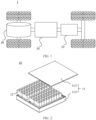
- FIG. 1 is a structural schematic diagram of a vehicle 1 according to an embodiment of this application.
- the vehicle 1 may be a fossil fuel vehicle, a natural-gas vehicle, or a new energy vehicle, where the new energy vehicle may be a battery electric vehicle, a hybrid electric vehicle, a range-extended vehicle, or the like.
- a motor 40, a controller 30, and a battery 10 may be provided inside the vehicle 1, where the controller 30 is configured to control the battery 10 to supply power to the motor 40.
- the battery 10 may be provided at the bottom, front, or rear of the vehicle 1.
- the battery 10 may be configured to supply power to the vehicle 1.
- the battery 10 may be used as an operational power source for the vehicle 1 that is configured for a circuit system of the vehicle 1, for example, to satisfy power needs of start, navigation, and running of the vehicle 1.
- the battery 10 can be used as not only the operational power source for the vehicle 1, but also as a driving power source for the vehicle 1, replacing or partially replacing fossil fuel or natural gas to provide driving traction for the vehicle 1.
- the battery 10 may include a plurality of battery cells.
- FIG. 2 is a structural schematic diagram of the battery 10 according to an embodiment of this application, the battery 10 may include a plurality of battery cells 12. Based on different power demands, battery cells 12 can be set in any quantity. The multiple battery cells 12 may be connected in series, parallel, or series-parallel to achieve greater capacity or power. Because each battery 10 may include a large number of battery cells 12, for ease of installation, the battery cells 12 may alternatively be provided in groups, and each group of battery cells 12 form a battery module. The number of battery cells 12 included in the battery module is not limited, and may be set according to requirements.
- the batteries may include a plurality of battery modules, which may be connected in series, parallel or mixed.
- the battery 10 may further include other structures.
- the battery 10 may further include a busbar, where the busbar is configured to implement an electrical connection among multiple battery cells 12, for example, a parallel connection, a series connection, or a series-parallel connection.
- the busbar may implement the electrical connection among the battery cells 12 by connecting electrode terminals of the battery cells 12.
- the busbar may be fixed to the electrode terminal of the battery cell 12 by welding. Electrical energy of the plurality of battery cells 12 can be further drawn out of the box through a conductive mechanism.
- the conductive mechanism may also belong to the busbar.
- the battery 10 may further include a box 11 (or referred to as a cover), where the box 11 has a hollow structure inside, and the plurality of battery cells 12 are accommodated in the box 11.
- the box 11 may include two portions: an upper box body 111 and a lower box body 112.
- the upper box body 111 and the lower box body 112 are snap-fitted together. Shapes of the upper box body 111 and the lower box body 112 may be determined based on a shape of the plurality of combined battery cells 12, and at least one of the upper box body 111 and the lower box body 112 has an opening.
- one of the upper box body 111 and the lower box body 112 included in the box 11 is a hollow cuboid with an opening, and the other is plate shaped for covering the opening.
- the lower box body 112 is a hollow cuboid and has only one face with an opening and the upper box body 111 is plate shaped.
- the upper box body 111 covers the opening of the lower box body 112 to form the box 11 with a closed chamber.
- the chamber may be configured to accommodate the plurality of battery cells 12.
- the upper box body 111 and the lower box body 112 included in the box 11 in this embodiment of this application may be in other shapes.
- the upper box body 111 and the lower box body 112 each may be a hollow cuboid and have only one face with an opening, where the opening of the upper box body 111 is disposed opposite the opening of the lower box body 112, and the upper box body 111 and the lower box body 112 are snap-fitted to form the box 11 with a closed chamber.
- the multiple battery cells 12 are connected in parallel, in series, or in series-parallel, and then placed into the box formed after the upper box body 111 and the lower box body 112 are snap-fitted.
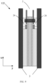
- FIG. 3 is a structural schematic diagram of a battery cell 12 according to an embodiment of this application.
- the battery cell 12 includes one or more electrode assemblies 122, a housing 121, and an end cover 124.
- the housing 121 and the end cover 124 form a housing or battery case.
- the wall of the housing 121 as well as the end cover 124 are referred to as the walls of the battery cell 12.
- the walls of the housing 121 include a bottom wall and four side walls, where the bottom wall and the four side walls are connected to form an accommodating space 123 for placing the electrode assembly 122.
- the housing 121 is shaped according to the shape of one or more electrode assemblies 122 combined.
- the housing 121 may be a hollow rectangular or square or cylindrical body, and one of the faces of the housing 121 has an opening so that the one or more electrode assemblies 122 may be placed within the housing 121.
- one face of the housing 121 is an opening face, which means that the face has no wall so that the inside and the outside of the housing 121 are in communication.
- the end face of the housing 121 is an opening face, which means that the end face has no wall so that the inside and the outside of the housing 121 are in communication.
- the end cover 124 covers the opening of the accommodating space 123 and is coupled to the housing 121 to form a closed cavity in which the electrode assembly 122 is placed.
- the housing 121 is filled with an electrolyte such as a liquid electrolyte.
- the battery cell 12 may also include two electrode terminals 1241.
- the two electrode terminals 1241 may be disposed on the end cover 124.
- the end cover 124 is generally in a shape of a flat plate, and the two electrode terminals 1241 are fixed on a flat surface of the end cover 124.
- the two electrode terminals 1241 are a positive electrode terminal 1241a and a negative electrode terminal 1241b respectively.
- Each electrode terminal 1241 is provided with a corresponding connecting member 125 or a current collection member.
- the current connection member is located between the end cover 124 and the electrode assembly 122 and is configured to electrically connect the electrode assembly 122 to the electrode terminal 1241.
- each electrode assembly 122 has a first tab 1221a and a second tab 1222a.
- the first tab 1221a and the second tab 1222a have opposite polarities.
- the first tab 1221a is a positive electrode tab
- the second tab 1222a is a negative electrode tab.
- the first tabs 1221a of one or more electrode assemblies 122 are connected to one electrode terminal through one connecting member 125
- the second tabs 1222a of one or more electrode assemblies 122 are connected to the other electrode terminal through the other connecting member 125.
- the positive electrode terminal 1241a is connected to the positive electrode tab through one connecting member 125
- the negative electrode terminal 1241b is connected to the negative electrode tab through the other connecting member 125.
- each electrode assembly 122 may be provided depending on an actual need. As shown in FIG. 3 , the battery cell 12 is provided with four independent electrode assemblies 122. Optionally, each electrode assembly 122 may include a negative electrode plate, a positive electrode plate, and a separator.
- FIG. 4 is a structural schematic exploded view of an electrode assembly 122 according to an embodiment of this application.
- the electrode assembly 122 includes an electrode plate 2 and a separator 3, where the electrode plate 2 further includes a positive electrode plate 2a and a negative electrode plate 2b.
- the negative electrode plate 2b, the positive electrode plate 2a, and the separator 3 are stacked along the second direction y.
- the separator 3 is provided between the positive electrode plate 2a and the negative electrode plate 2b to separate the positive electrode plate 2a and the negative electrode plate 2b.
- a size of the negative electrode plate 2b is larger than a size of the positive electrode plate 2a, and a positive projection of the positive electrode plate 2a on a plane in which a surface of the negative electrode plate 2b is located does not exceed the negative electrode plate 2b.
- the first direction x is a width direction of the positive electrode plate 2a, the negative electrode plate 2b, or the separator 3
- the second direction y is perpendicular to the first direction x
- the second direction y is in a thickness direction of the negative electrode plate 2b, the positive electrode plate 2a, or the separator 3, that is, the negative electrode plate 2b, the positive electrode plate 2a, and the separator 3 are stacked along their thickness direction.
- the negative electrode plate 2b includes a negative electrode current collector and a negative electrode active substance layer provided on the negative electrode current collector.
- the negative electrode active substance layer may include a carbon material, such as graphite, soft carbon (such as coke), and hard carbon, or may include a non-carbon material, such as nitride, PAS, tin-based oxides, tin alloys, nano-negative electrode materials, and some other intermetallic compounds.
- the negative electrode current collector collects the current generated by the negative electrode active substance layer in order to form a larger current for external output. Therefore, the negative electrode current collector should have sufficient contact with the negative electrode active material, and it is preferable for the internal resistance to be as small as possible.
- the positive electrode plate 2a includes a positive electrode current collector and a positive electrode active substance layer disposed on the positive electrode current collector.
- the positive electrode active substance layer may include a lithium-nickel oxide, a lithium-cobalt oxide, a lithium-titanium oxide, a nickel-cobalt polyoxide, a lithium-manganese oxide, a lithium-iron-phosphorus oxide, and the like.
- the positive electrode current collector collects the current generated by the positive electrode active substance layer in order to form a larger current for external output. Therefore, the positive electrode current collector should have sufficient contact with the positive electrode active material, and it is preferable for the internal resistance to be as small as possible.
- the separator 3 is one of the key inner components.
- the performance of the separator 3 determines the interface structure and internal resistance of the battery 10, and directly affects the capacity, cycling, safety performance and other characteristics of the battery 10.
- the separator 3 with excellent performance plays an important role in improving the overall performance of the battery 10.
- the main function of the separator 3 is to separate the positive electrode plate 2a and the negative electrode plate 2b of the battery 10, to prevent the two poles from contacting and short-circuiting.
- the separator 3 further has the function of allowing electrolyte ions to pass through.
- the separator 3 material is non-conductive, and its physical and chemical properties have a great influence on the performance of the battery 10.
- Different types of batteries 10 use different separators 3.
- a separator 3 material that is resistant to organic solvents is needed.
- a high-strength, thin-film polyolefin porous membrane is used.
- metal burrs inevitably present on the current collector of the electrode plate affect the performance of the battery 10.
- the structure of the electrode plate and electrode assembly of a battery provided in this application is illustrated below with reference to FIG. 5 to FIG. 9 .
- FIG. 5 is a structural schematic diagram of an electrode plate 2 of a battery according to an embodiment of this application. (a) in FIG. 5 illustrates a side view of the electrode plate 2, and (b) in FIG. 5 illustrates a main view of the electrode plate 2.
- the electrode plate 2 shown in FIG. 5 may be a negative electrode plate or a positive electrode plate, and this application does not limit this.
- the electrode plate 2 includes a current collector 20, an active substance layer 21, and a conductive structure 22.
- the current collector 20 includes a main body portion 201a and a tab portion 202a disposed in a first direction x.
- the main body portion 201a is covered with the active substance layer 21, and the tab portion 202a is not covered with the active substance layer 21.
- a first region 221 of the conductive structure 22 is welded to a portion of the tab portion 202a to form a welding mark zone 23.
- At least a portion of the welding mark zone 23 being covered with a protective layer 24, which means that the entire or a portion of the welding mark zone 23 can be covered with the protective layer 24.
- all portions of the welding mark zone 23 are covered with a protective layer 24.
- the conductive structure 22 may be a metal foil, such as a Cu/Al foil, which is not limited by the embodiments of this application.
- the conductive structure 22 is welded to the tab portion 202a of the current collector 20 so as to ensure the current flow capability.
- the welding may be in the form of roll welding.
- the welding may result in metal particles being generated in the welding mark zone 23, and the metal particles may pierce through the separator.
- the protective layer 24 is utilized to cover the welding mark zone 23 to avoid piercing through the separator.
- the protective layer 24 can cover metal particles generated in the welding mark zone 23 due to the welding process. This can prevent the metal particles from piercing through the separator and leading to short circuit in the battery, improving the safety of the battery.
- the current collector 20 may include a first support layer 201b and a metal layer 202b provided on each of on two sides of the first support layer 201b; and the conductive structure 22 is welded to a portion of the metal layer 202b of the tab portion 202a to form the welding mark zone 23.
- the current collector 20 when the current collector 20 includes the first support layer 201b and the metal layer 202b provided on each of the two sides of the first support layer 201b, the current collector 20 may be a composite substrate.
- the conductive structure 22 is welded to the metal layer 202b of the current collector 20.
- the Cu/Al foil being welded to the metal layer of the composite substrate can allow the electric current generated by the metal layer of the composite substrate to be gradually directed to the tab, electrode post, and the like of the battery through the Cu/Al foil.
- the conductive structure 22 includes a second region 222, the first region 221, and a third region 223 disposed in the first direction x, where the second region 222 is closer to the main body portion 201a relative to the first region 221, the third region 223 is farther away from the main body portion 201a relative to the first region 221, and an edge of the second region 222 closer to the main body portion 201a is covered with the protective layer 24.
- the first region 221 is a region on the conductive structure 22 used for welding to the metal layer 202b of the current collector 20. If a direction indicated by the first direction x is up and a direction opposite to the direction indicated by the first direction x is down, the second region 222 is a region below the first region 221, and the third region 223 is a region above the first region 221.
- the edge of the second region 222 of the electrode plate 2 shown in FIG. 6 is covered with the protective layer 24. That is, a difference as compared to FIG. 5 is that in the electrode plate 2 shown in FIG. 6 , the edge of the second region 222 is also covered with the protective layer 24 in addition to the welding mark zone 23 being covered with the protective layer 24.
- the protective layer 24 covering the edge of the second region 222 it is possible to prevent the edge of the second region 222 of the conductive structure 22 from piercing through the separator and leading to short circuit in the battery, improving the safety of the battery.
- the second region 222 is covered with the protective layer 24.
- the second region 222 is all covered with the protective layer 24, instead of only covering the edge of the second region 222 with the protective layer. This can better avoid the risk of piercing through the separator when the second region 222 is folded over, improving the safety of the battery.
- the second region 222 of the electrode plate 2 shown in FIG. 7 are all covered with the protective layer 24.
- the protective layer 24 in FIG. 7 covers all of the welding mark zone 23 and the second region 222, thereby better avoiding the risk of piercing through the separator by the metal particles or when the second region 222 is folded over.
- size L5 of the protective layer 24 in the first direction x is greater than or equal to a sum of size L3 of the welding mark zone 23 in the first direction x and size L2 of the second region 222 in the first direction x.
- the size L5 of the protective layer 24, the size L3 of the welding mark zone 23, and the size L2 of the second region 222 in the first direction x may be widths of the protective layer 24, the welding mark zone 23, and the second region 222, respectively.
- the width of the protective layer 24 is greater than or equal to a sum of the widths of the welding mark zone 23 and the second region 222.
- setting the size of the protective layer 24 in the first direction x allows the protective layer 24 to cover the welding mark zone 23 and the second region 222, preventing the second region 222 and metal particles in the welding mark zone 23 from piercing through the separator, thereby improving the safety of the battery.
- the above size L3 of the welding mark zone 23 in the first direction x may range from 2 mm to 8 mm. Limiting the welding mark zone 23 to remain within a specified size range can maintain process stability in the production of the battery and a higher energy density of the battery while ensuring the current flow capability of the conductive structure 22.
- the above-described size L2 of the second region 222 in the first direction x may range from 0 mm to 1 mm.
- the size L2 of the second region 222 of the conductive structure 22 in the first direction x limited to be greater than or equal to 0 mm, it is possible to prevent the current collector 20 from being pressed by a weld head in welding to cause damage to the current collector 20 and affect the conductivity and long-term stability of the current collector 20.
- L2 limited to be less than or equal to 1 mm, it is possible to avoid folding of the conductive structure 22 and other problems, thereby improving the safety of the battery.
- the size of the second region 222 in the first direction x may be equal to 0 mm. However, in actual production, due to factors such as the device tolerance, the size of the second region 222 in the first direction x is usually greater than 0 mm.
- the size of the protective layer 24 in the second direction y is greater than or equal to the size of the conductive structure 22 in the second direction y.
- the second direction y is the thickness direction of the electrode plate 2, and the second direction y is perpendicular to the first direction x.
- the sizes of the protective layer 24 and the conductive structure 22 in the second direction y may be the thickness of the protective layer 24 and the thickness of the conductive structure 22, respectively. Under a condition that the protective layer 24 and the conductive structure 22 are located in a same plane, the thickness of the protective layer 24 needs to be greater than or equal to the thickness of the conductive structure 22 for the protective layer 24 to cover a sharp portion of the edge of the conductive structure 22.
- the size of the protective layer 24 in the second direction y limited to be greater than or equal to the size of the conductive structure 22 in the second direction y, it is possible to ensure that the sharp portion of the edge of the conductive structure 22 is completely covered, completely avoiding the possibility of the edge of the conductive structure 22 piercing through the separator.
- the surface of the protective layer 24 farther away from the current collector 20 does not exceed the surface of the active substance layer 21 farther away from the current collector 20.
- the protective layer 24 does not protrude from the surface of the electrode plate 2, thereby avoiding the problem of edge curling during the winding process of the electrode plate and ensuring high production efficiency of the battery.
- the protective layer 24 is an insulation adhesive.
- the insulation adhesive can further reduce the risk of short circuit in the battery while covering metal particles that may pierce through the separator.
- a second insulation layer 25 is applied between the conductive structure 22 and the active substance layer 21. That is, the second insulation layer 25 is applied to a portion of the tab portion 202a that is close to the main body portion 201a and not covered with the conductive structure 22.
- the second insulation layer 25 is AT11.
- the second insulation layer 25 can prevent both the active material and the welding mark zone 23 from being cut during the laser die-cutting of the tab, improving the battery production efficiency.
- the second insulation layer 25 has a size L1 in the first direction x of 1 mm-3 mm.
- limiting the size of the second insulation layer 25 in the first direction x can prevent the width of the second insulation layer 25 from affecting the height of the jelly cell.
- the surface of the protective layer 24 farther away from the current collector 20 exceeds the surface of the second insulation layer 25 farther away from the current collector 20, where the second direction y is the thickness direction of the electrode plate, and the second direction y is perpendicular to the first direction x.
- the protective layer 24 and the second insulation layer 25 at least partially overlap.
- the second insulation layer 25 is at least partially covered with the protective layer 24.
- the protective layer 24 and the second insulation layer 25 are disposed to at least partially overlap. Since the second insulation layer 25 may abut against the conductive structure 22, or there may be a gap between them, with the protective layer 24 and the second insulation layer 25 that are disposed to overlap, it is possible to ensure that the protective layer 24 completely covers the edge of the conductive structure 22, ensuring the safety of the battery.
- FIG. 8 shows a structural schematic diagram of the electrode plate 2 when the protective layer 24 partially overlaps with the second insulation layer 25 and the outer surface of the protective layer 24 exceeds the outer surface of the second insulation layer 25. It can be seen from FIG. 8 that in this case, the protective layer 24 can completely cover the edge of the second region 222 of the conductive structure 22. In practice, due to the influence of factors such as device tolerances, providing the protective layer 24 to cover a portion of the second insulation layer 25 can make it easy to cover the edge of the second region 222, avoiding the risk of the separator being pierced through, thereby guaranteeing the safety of the battery.
- the size L7 of the welding mark zone 23 in the second direction y is less than or equal to the sum L6 of the sizes of the current collector 20 and the active substance layer 21 in the second direction y.
- the second direction y is the thickness direction of the electrode plate, and the second direction y is perpendicular to the first direction x.
- limiting the size of the welding mark zone 23 in the second direction y can avoid the problem of edge curling during the winding of the electrode plate, ensuring high production efficiency of the battery.
- the structure of the electrode plate 2 shown in FIGs. 6 to 8 are similar to that of the electrode plate 2 shown in FIG. 5 , with the difference being the coverage area of the protective layer 24.
- the relevant explanations in FIG. 5 The details are not repeated here in the embodiment of this application.
- An embodiment of this application further provides an electrode assembly 122, where the electrode assembly 122 can include the electrode plate 2 according to any one of the embodiments described above.
- the electrode assembly 122 may further include the separator 3, and in the second direction y, the surface of the protective layer 24 farther away from the current collector 20 abuts against the surface of the separator 3 closer to the electrode plate 2.
- the electrode assembly 122 includes the electrode plate 2 and the separator 3, and in the second direction y, the surface of the protective layer 24 included in the electrode plate 2 farther away from the current collector 20 abuts against the surface of the separator 3 closer to the electrode plate 2. It can be understood that for the specific structure of the electrode plate 2 shown in FIG. 9 , reference may be made to the relevant structures shown in FIGs. 5 to 8 , and the same reference numerals represent the same structures, explanation of which is not repeated herein.
- the battery cell 12 may include the electrode assembly 122 in the preceding embodiments; a housing having an opening for accommodating the electrode assembly 122; and an end cover for closing the opening of the housing.
- An embodiment of this application further provides a battery 10, where the battery 10 may include the battery cell 12 in the foregoing embodiments.
- the battery 10 may also include other structures such as a box and a busbar. Details are not repeated herein.
- An embodiment of this application further provides an electric device, where the electric device may include the battery 10 in the foregoing embodiments.
- the electric device can be a vehicle 1, ship, spacecraft, or the like, which is not limited in the embodiment of this application.
Landscapes
- Chemical & Material Sciences (AREA)
- Chemical Kinetics & Catalysis (AREA)
- Electrochemistry (AREA)
- General Chemical & Material Sciences (AREA)
- Engineering & Computer Science (AREA)
- Materials Engineering (AREA)
- Composite Materials (AREA)
- Connection Of Batteries Or Terminals (AREA)
- Battery Electrode And Active Subsutance (AREA)
Abstract
Description
- This application relates to the technical field of batteries, and in particular, to a battery electrode plate, an electrode assembly, a battery cell, a battery, and an electric device.
- As technology continues to advance, power batteries are widely used in a variety of fields such as energy storage power systems, electric transportation vehicles, military equipment, and aerospace. The improvement of battery technology is crucial.
- In the development of battery technology, performance and safety issues of batteries cannot be ignored. Therefore, enhancing the safety of batteries is an urgent problem to be addressed in battery technology.
- Embodiments of this application provide a battery electrode plate, an electrode assembly, a battery cell, a battery, and an electric device, which can improve battery safety.
- According to a first aspect, a battery electrode plate is provided, including a current collector, an active substance layer, and a conductive structure; where the current collector includes a main body portion and a tab portion disposed in a first direction, where the main body portion is covered with the active substance layer and the tab portion is not covered with the active substance layer; and a first region of the conductive structure is welded to a portion of the tab portion to form a welding mark zone, at least a portion of the welding mark zone being covered with a protective layer.
- In the embodiments of this application, with the protective layer applied to at least a portion of the welding mark zone between the current collector and the conductive structure, the protective layer can cover metal particles generated in the welding mark zone due to the welding process. This can prevent the metal particles from piercing through the separator and leading to short circuit in the battery, improving battery safety.
- In a possible embodiment, the current collector includes a first support layer and a metal layer provided on each of the two sides of the first support layer; and the conductive structure is welded to a portion of the metal layer of the tab portion to form the welding mark zone.
- In the above embodiment, with the current collector of a three-layer structure and the conductive structure welded to the current collector, it is possible to improve the conductivity of the current collector while reducing the weight of the battery.
- In a possible embodiment, the conductive structure includes a second region, the first region, and a third region disposed in the first direction, where the second region is closer to the main body portion relative to the first region, the third region is farther away from the main body portion relative to the first region, and an edge of the second region closer to the main body portion is covered with the protective layer.
- In the above embodiment, with the protective layer covering the edge of the second region, it is possible to prevent the edge of the second region of the conductive structure from piercing through the separator and leading to short circuit in the battery, improving the safety of the battery.
- In a possible embodiment, the second region is covered with the protective layer.
- In the above embodiment, the risk of piercing through the separator when the second region is folded over can be avoided, improving the safety of the battery.
- In a possible embodiment, size L5 of the protective layer in the first direction is greater than or equal to a sum of size L3 the welding mark zone in the first direction and size L2 of the second region in the first direction.
- In the above embodiment, the size of the protective layer in the first direction is set such that the protective layer covers the welding mark zone and the second region, preventing the metal particles present in the welding mark zone and the second region from piercing through the separator, thereby improving the safety of the battery.
- In one possible embodiment, L3 ranges from 2 mm to 8 mm.
- In the above embodiment, with the welding mark zone limited to remain within a specified size range, it is possible to maintain process stability of battery production and a higher energy density of the battery while ensuring the current flow capability of the conductive structure.
- In one possible embodiment, L2 ranges from 0 mm to 1 mm.
- In the above embodiment, with the size L2 of the second region of the conductive structure in the first direction limited to be greater than or equal to 0 mm, it is possible to prevent the current collector from being pressed by a weld head in welding, thereby avoiding damage to the current collector without affecting the conductivity and long-term stability of the current collector. In addition, with L2 limited to be less than or equal to 1 mm, it is possible to avoid folding of the conductive structure and other problems, thereby improving the safety of the battery.
- In a possible embodiment, size of the protective layer in the second direction is greater than or equal to size of the conductive structure in the second direction, where the second direction is in a thickness direction of the electrode plate, and the second direction is perpendicular to the first direction.
- In the above embodiment, with the size of the protective layer in the second direction limited to be greater than or equal to the size of the conductive structure in the second direction, it is possible to ensure that a sharp portion of the edge of the conductive structure is completely covered, completely avoiding the possibility of the edge of the conductive structure piercing through the separator.
- In a possible embodiment, in the second direction, a surface of the protective layer farther away from the current collector does not exceed beyond a surface of the active substance layer farther away from the current collector.
- In the above embodiment, the protective layer does not protrude from the surface of the electrode plate, thereby avoiding the problem of edge curling during the winding process of the electrode plate and ensuring high production efficiency of the battery.
- In a possible embodiment, the protective layer is an insulation adhesive.
- In the above embodiment, the insulation adhesive covers metal particles that may pierce through the separator, thereby further reducing the risk of short circuit in the battery.
- In a possible embodiment, a second insulation layer is applied between the conductive structure and the active substance layer.
- In the above embodiment, the second insulation layer can prevent both the active material and the welding mark zone from being cut during the laser cutting of the tab, thereby improving the production efficiency of the battery.
- In a possible embodiment, the second insulation layer has a size L1 of 1 mm-3 mm in the first direction.
- In the above embodiment, limiting the size of the second insulation layer in the first direction can avoid affecting battery safety due to the size of the second insulation layer in the first direction.
- In a possible embodiment, in the second direction, a surface of the protective layer farther away from the current collector exceeds a surface of the second insulation layer farther away from the current collector, where the second direction is in a thickness direction of the electrode plate, and the second direction is perpendicular to the first direction.
- In the above embodiment, with the surface of the protective layer farther away from the current collector exceeding the surface of the second insulation layer farther away from the current collector, that is, with the outer surface of the protective layer exceeding the outer surface of the second insulation layer, it is possible to ensure that the edge of the conductive structure is completely covered to prevent the edge of the conductive structure from piercing through the separator, ensuring the safety of the battery.
- In a possible embodiment, the protective layer and the second insulation layer at least partially overlap.
- In the above embodiment, the protective layer and the second insulation layer are disposed to at least partially overlap. Since the second insulation layer may abut against the conductive structure or there may be a gap between them, with the protective layer and the second insulation layer that are disposed to overlap it is possible to ensure that the protective layer completely covers the edge of the conductive structure, ensuring the safety of the battery.
- In a possible embodiment, size of the welding mark zone in the second direction is less than or equal to a sum L6 of sizes of the current collector and the active substance layer in the second direction, where the second direction is in a thickness direction of the electrode plate, and the second direction is perpendicular to the first direction.
- In the above embodiment, limiting the size of the welding mark zone in the second direction can avoid the problem of edge curling during the winding of the electrode plate, ensuring high production efficiency of the battery.
- According to a second aspect, an electrode assembly is provided, including the electrode plate according to the first aspect described above or according to any possible embodiment of the first aspect.
- In one possible embodiment, the electrode assembly further includes a separator, and a surface of the protective layer farther away from the current collector abuts against a surface of the separator closer to the electrode plate in a second direction, where the second direction is in a thickness direction of the electrode plate, and the second direction is perpendicular to the first direction.
- In the above embodiment, with the surface of the protective layer farther away from the current collector being set to abut against the surface of the separator closer to the electrode plate, metal particles generated due to welding can be blocked from falling through a gap between the electrode plate and the separator, thereby preventing the metal particles from piercing through the separator and reducing the risk of short circuit in the battery.
- According to a third aspect, a battery cell is provided, including the electrode assembly according to the second aspect or any possible embodiment of the second aspect; a housing having an opening for accommodating the electrode assembly; and an end cover for closing the opening.
- According to a fourth aspect, a battery is provided, including the battery cell according to the third aspect or any possible embodiment of the third aspect described above.
- According to a fifth aspect, an electric device is provided, including the battery according to the fourth aspect or any possible embodiment of the fourth aspect, where the battery is used to supply electric energy.
- To describe the technical solutions of the embodiments of this application more clearly, the following briefly describes the accompanying drawings required for describing the embodiments of this application. It will be apparent that the accompanying drawings described below show merely some embodiments of this application, and persons of ordinary skill in the art may still derive other drawings from the accompanying drawings without creative efforts.
-
FIG. 1 is a structural schematic diagram of a vehicle according to an embodiment of this application; -
FIG. 2 is a structural schematic exploded view of a battery according to an embodiment of this application; -
FIG. 3 is a structural schematic exploded view of a battery cell according to an embodiment of this application; -
FIG. 4 is a structural schematic exploded view of an electrode assembly according to an embodiment of this application; -
FIG. 5 is a structural schematic diagram of an electrode plate of a battery according to an embodiment of this application; -
FIG. 6 is a structural schematic diagram of an electrode plate of a battery according to an embodiment of this application; -
FIG. 7 is a structural schematic diagram of an electrode plate of a battery according to an embodiment of this application; -
FIG. 8 is a structural schematic diagram of an electrode plate of a battery according to an embodiment of this application; and -
FIG. 9 is a structural schematic diagram of an electrode assembly according to an embodiment of this application. - The accompanying drawings are not drawn to scale.
- The following further describes the implementations of this application in detail with reference to the accompanying drawings and embodiments. The detailed description of embodiments and the accompanying drawings are intended to illustrate the principle of this application, rather than to limit the scope of this application, meaning this application is not limited to the embodiments described herein.
- In the description of this application, it should be noted that, unless otherwise stated, "multiple" means at least two; and the orientations or positional relationships indicated by the terms "upper", "lower", "left", "right", "inside", "outside", and the like are merely for ease and brevity of description of this application rather than indicating or implying that the means or components mentioned must have specific orientations or must be constructed or manipulated according to particular orientations. These terms shall therefore not be construed as limitations on this application. In addition, the terms "first", "second", "third", and the like are merely for the purpose of description and shall not be understood as any indication or implication of relative importance. "Perpendicular" is not perpendicular in the strict sense but within an allowable range of error. "Parallel" is not parallel in the strict sense but within an allowable range of error.
- The orientation terms appearing in the following description are all directions shown in the figures, and do not limit the specific structure of the application. In the description of this application, it should also be noted that unless otherwise specified and defined explicitly, the terms "mount", "connect", and "join" should be understood in their general senses. For example, they may be a fixed connection, a detachable connection, or an integral connection, and may be a direct connection or an indirect connection via an intermediate medium. Persons of ordinary skill in the art can understand the specific meanings of these terms in this application as appropriate to the specific situations.
- In the embodiments of this application, like reference signs denote like components, and for brevity, in different embodiments, detailed descriptions of like components are not repeated. It should be understood that, as shown in the accompanying drawings, sizes such as thickness, length, and width of various components and sizes such as thickness, length, and width of integrated devices in the embodiments of this application are merely for illustrative purposes and should not constitute any limitations on this application.
- The term "and/or" in this application is only an associative relationship for describing associated objects, indicating that three relationships may be present. For example, A and/or B may indicate three cases: presence of only A; presence of both A and B; and presence of only B. In addition, the character "/" in this application generally indicates an "or" relationship between contextually associated objects.
- Unless otherwise defined, all technical and scientific terms used in this application shall have the same meanings as commonly understood by those skilled in the art to which this application relates. The terms used in the specification of this application are intended to merely describe the specific embodiments rather than to limit this application. The terms "include", "comprise", and any variations thereof in the specification and claims of this application as well as the foregoing description of drawings are intended to cover non-exclusive inclusions. In the specification, claims, or accompanying drawings of this application, the terms "first", "second", and the like are intended to distinguish between different objects rather than to indicate a particular order or relative importance.
- Reference to "embodiment" in this application means that specific features, structures, or characteristics described with reference to the embodiment may be included in at least one embodiment of this application. The word "embodiment" appearing in various places in the specification does not necessarily refer to the same embodiment or an independent or alternative embodiment that is exclusive of other embodiments. It is explicitly or implicitly understood by persons skilled in the art that the embodiments described herein may be combined with other embodiments.
- In this application, the battery may include a lithium-ion secondary battery, a lithium-ion primary battery, a lithium-sulfur battery, a sodium-lithium-ion battery, a sodium-ion battery, a magnesium-ion battery, or the like. This is not limited in the embodiments of this application. The battery cell encapsulated in the battery may be cylindrical, flat, cuboid, or of other shapes, which is not limited in the embodiments of this application either. Battery cells are typically divided into three types by packaging method: cylindrical cell, prismatic cell, and pouch cell. The type of battery is not limited In the embodiments of this application either.
- The battery mentioned in the embodiments of this application is a single physical module that includes one or more battery cells for providing a higher voltage and capacity. For example, the battery mentioned in this application may include a battery module, a battery pack, or the like. A battery typically includes a box configured to enclose one or more battery cells. The box can prevent liquids or other foreign matter from affecting charging or discharging of the battery cell.
- The battery cell includes an electrode assembly and an electrolyte. The electrode assembly includes a positive electrode plate, a negative electrode plate, and a separator. Working of the battery cell mainly relies on the migration of metal ions between the positive electrode plate and the negative electrode plate. The positive electrode plate includes a positive electrode current collector and a positive electrode active substance layer. The positive electrode active substance layer is applied on a surface of the positive electrode current collector. The part of positive electrode current collector uncoated with the positive electrode active substance layer protrudes out of the part of positive electrode current collector coated with the positive electrode active substance layer and serves as a positive electrode tab. The positive electrode current collector and the negative electrode current collector may be collectively referred to as the current collector. A lithium-ion battery is used as an example, for which, the positive electrode current collector may be made of aluminum and the positive electrode active substance may be lithium cobaltate, lithium iron phosphate, ternary lithium, lithium manganate, or the like. The negative electrode plate includes a negative electrode current collector and a negative electrode active substance layer. The negative electrode active substance layer is applied on a surface of the negative electrode current collector. A current collector uncoated with the negative electrode active substance layer protrudes from the current collector coated with the negative electrode active substance layer and serves as a negative electrode tab. The negative electrode current collector may be made of copper, and the negative electrode active substance may be graphite, carbon, silicon, or the like. To allow a large current to pass through without any fusing, multiple positive electrode tabs are provided and stacked together, and multiple negative electrode tabs are provided and stacked together. The separator may be made of polypropylene (PP), polyethylene (PE), or the like. In addition, the electrode assembly may be a wound structure or a stacked structure. However, the embodiments of this application are not limited thereto.
- At present, with the continuous progress of science and technology, power batteries are increasingly used. Traction batteries have been not only used in energy storage power supply systems such as hydroelectric power plants, thermal power plants, wind power plants, and solar power plants, but also widely used in many other fields including electric transportation tools such as electric bicycles, electric motorcycles, and electric vehicles, military equipment, and aerospace. With the continuous expansion of the application field of power battery, the market demand is increasing, and types of traction batteries demanded in the market are also increasing.
- In battery technology, the material of the current collector can be a single metal layer, such as copper foil or aluminum foil, or a composite substrate. The structure of the composite substrate is similar to a "sandwich", with a support layer in the middle and metal layers on both sides of the support layer. When the composite substrate is used as a current collector, the outer two layers of the composite substrate need to be connected by Cu/Al foil, that is, the Cu/Al foil is welded to the composite substrate to ensure that the current carried by the composite substrate is introduced into a tab, and then from the tab to an electrode post. Or in other words, the welded Cu/Al foil will subsequently form into a tab through a procedure such as cutting. It can be understood that a support layer of the composite substrate may be an insulation layer.
- However, when the Cu/Al foil is welded to the composite substrate, metal particles will appear in a contact area between the composite substrate and the Cu/Al foil and around the contact area due to the welding process, and the metal particles as well as the edge of the Cu/Al foil may pierce through the insulation layer, leading to short circuit between the positive electrode and the negative electrode, resulting in internal short circuit in the battery cell.
- In view of this, this application provides a battery electrode plate. The electrode plate includes a current collector, an active substance layer, and a conductive structure. The current collector includes a main body portion and a tab portion disposed in a first direction, the main body portion being covered with the active substance layer, and the tab portion being not covered with the active substance layer; and a first region of the conductive structure is welded to a portion of the tab portion to form a welding mark zone, at least a portion of the welding mark zone being covered with a protective layer. Thereby, with the protective layer applied to at least a portion of the welding mark zone between the current collector and the conductive structure, the protective layer can cover metal particles generated in the welding mark zone due to the welding process. This prevents the metal particles from piercing through the separator, thus further reducing the risk of short circuit in the battery cell and improving the safety of the quality of the battery.
- The technical solutions described in the embodiments of this application are applicable to various apparatuses that use batteries, for example, mobile phones, portable devices, notebook computers, electric bicycles, electric toys, electric tools, electric vehicles, ships, and spacecrafts. For example, spacecrafts include airplanes, rockets, space shuttles, and spaceships.
- It should be understood that the technical solutions described in the embodiments of this application are not only applicable to the devices described above, but also applicable to all devices using batteries. However, for brevity of description, in the following embodiments, the electric vehicle is used as an example for description.
- For example,
FIG. 1 is a structural schematic diagram of avehicle 1 according to an embodiment of this application. Thevehicle 1 may be a fossil fuel vehicle, a natural-gas vehicle, or a new energy vehicle, where the new energy vehicle may be a battery electric vehicle, a hybrid electric vehicle, a range-extended vehicle, or the like. Amotor 40, acontroller 30, and abattery 10 may be provided inside thevehicle 1, where thecontroller 30 is configured to control thebattery 10 to supply power to themotor 40. For example, thebattery 10 may be provided at the bottom, front, or rear of thevehicle 1. Thebattery 10 may be configured to supply power to thevehicle 1. For example, thebattery 10 may be used as an operational power source for thevehicle 1 that is configured for a circuit system of thevehicle 1, for example, to satisfy power needs of start, navigation, and running of thevehicle 1. In another embodiment of this application, thebattery 10 can be used as not only the operational power source for thevehicle 1, but also as a driving power source for thevehicle 1, replacing or partially replacing fossil fuel or natural gas to provide driving traction for thevehicle 1. - To meet different requirements for power use, the
battery 10 may include a plurality of battery cells. For example,FIG. 2 is a structural schematic diagram of thebattery 10 according to an embodiment of this application, thebattery 10 may include a plurality ofbattery cells 12. Based on different power demands,battery cells 12 can be set in any quantity. Themultiple battery cells 12 may be connected in series, parallel, or series-parallel to achieve greater capacity or power. Because eachbattery 10 may include a large number ofbattery cells 12, for ease of installation, thebattery cells 12 may alternatively be provided in groups, and each group ofbattery cells 12 form a battery module. The number ofbattery cells 12 included in the battery module is not limited, and may be set according to requirements. The batteries may include a plurality of battery modules, which may be connected in series, parallel or mixed. - Optionally, the
battery 10 may further include other structures. For example, thebattery 10 may further include a busbar, where the busbar is configured to implement an electrical connection amongmultiple battery cells 12, for example, a parallel connection, a series connection, or a series-parallel connection. Specifically, the busbar may implement the electrical connection among thebattery cells 12 by connecting electrode terminals of thebattery cells 12. Further, the busbar may be fixed to the electrode terminal of thebattery cell 12 by welding. Electrical energy of the plurality ofbattery cells 12 can be further drawn out of the box through a conductive mechanism. Optionally, the conductive mechanism may also belong to the busbar. - The
battery 10 may further include a box 11 (or referred to as a cover), where thebox 11 has a hollow structure inside, and the plurality ofbattery cells 12 are accommodated in thebox 11. As shown inFIG. 2 , thebox 11 may include two portions: an upper box body 111 and alower box body 112. The upper box body 111 and thelower box body 112 are snap-fitted together. Shapes of the upper box body 111 and thelower box body 112 may be determined based on a shape of the plurality of combinedbattery cells 12, and at least one of the upper box body 111 and thelower box body 112 has an opening. For example, one of the upper box body 111 and thelower box body 112 included in thebox 11 is a hollow cuboid with an opening, and the other is plate shaped for covering the opening. For example, as shown inFIG. 2 , thelower box body 112 is a hollow cuboid and has only one face with an opening and the upper box body 111 is plate shaped. In such case, the upper box body 111 covers the opening of thelower box body 112 to form thebox 11 with a closed chamber. The chamber may be configured to accommodate the plurality ofbattery cells 12. - Optionally, the upper box body 111 and the
lower box body 112 included in thebox 11 in this embodiment of this application may be in other shapes. For example, the upper box body 111 and thelower box body 112 each may be a hollow cuboid and have only one face with an opening, where the opening of the upper box body 111 is disposed opposite the opening of thelower box body 112, and the upper box body 111 and thelower box body 112 are snap-fitted to form thebox 11 with a closed chamber. Themultiple battery cells 12 are connected in parallel, in series, or in series-parallel, and then placed into the box formed after the upper box body 111 and thelower box body 112 are snap-fitted. -
FIG. 3 is a structural schematic diagram of abattery cell 12 according to an embodiment of this application. Thebattery cell 12 includes one ormore electrode assemblies 122, ahousing 121, and anend cover 124. Thehousing 121 and theend cover 124 form a housing or battery case. The wall of thehousing 121 as well as theend cover 124 are referred to as the walls of thebattery cell 12. For a rectangular-type battery cell 12, the walls of thehousing 121 include a bottom wall and four side walls, where the bottom wall and the four side walls are connected to form anaccommodating space 123 for placing theelectrode assembly 122. Thehousing 121 is shaped according to the shape of one ormore electrode assemblies 122 combined. For example, thehousing 121 may be a hollow rectangular or square or cylindrical body, and one of the faces of thehousing 121 has an opening so that the one ormore electrode assemblies 122 may be placed within thehousing 121. For example, when thehousing 121 is a hollow cuboid or cube, one face of thehousing 121 is an opening face, which means that the face has no wall so that the inside and the outside of thehousing 121 are in communication. When thehousing 121 is a hollow cylinder, the end face of thehousing 121 is an opening face, which means that the end face has no wall so that the inside and the outside of thehousing 121 are in communication. Theend cover 124 covers the opening of theaccommodating space 123 and is coupled to thehousing 121 to form a closed cavity in which theelectrode assembly 122 is placed. Thehousing 121 is filled with an electrolyte such as a liquid electrolyte. - The
battery cell 12 may also include twoelectrode terminals 1241. The twoelectrode terminals 1241 may be disposed on theend cover 124. Theend cover 124 is generally in a shape of a flat plate, and the twoelectrode terminals 1241 are fixed on a flat surface of theend cover 124. The twoelectrode terminals 1241 are a positive electrode terminal 1241a and a negative electrode terminal 1241b respectively. Eachelectrode terminal 1241 is provided with a corresponding connectingmember 125 or a current collection member. The current connection member is located between theend cover 124 and theelectrode assembly 122 and is configured to electrically connect theelectrode assembly 122 to theelectrode terminal 1241. - As shown in
FIG. 3 , eachelectrode assembly 122 has afirst tab 1221a and asecond tab 1222a. Thefirst tab 1221a and thesecond tab 1222a have opposite polarities. For example, when thefirst tab 1221a is a positive electrode tab, thesecond tab 1222a is a negative electrode tab. Thefirst tabs 1221a of one ormore electrode assemblies 122 are connected to one electrode terminal through one connectingmember 125, and thesecond tabs 1222a of one ormore electrode assemblies 122 are connected to the other electrode terminal through the other connectingmember 125. For example, the positive electrode terminal 1241a is connected to the positive electrode tab through one connectingmember 125, and the negative electrode terminal 1241b is connected to the negative electrode tab through the other connectingmember 125. - In the
battery cell 12, one ormore electrode assemblies 122 may be provided depending on an actual need. As shown inFIG. 3 , thebattery cell 12 is provided with fourindependent electrode assemblies 122. Optionally, eachelectrode assembly 122 may include a negative electrode plate, a positive electrode plate, and a separator. -
FIG. 4 is a structural schematic exploded view of anelectrode assembly 122 according to an embodiment of this application. As shown inFIG. 4 , theelectrode assembly 122 includes anelectrode plate 2 and aseparator 3, where theelectrode plate 2 further includes apositive electrode plate 2a and anegative electrode plate 2b. - Specifically, the
negative electrode plate 2b, thepositive electrode plate 2a, and theseparator 3 are stacked along the second direction y. Theseparator 3 is provided between thepositive electrode plate 2a and thenegative electrode plate 2b to separate thepositive electrode plate 2a and thenegative electrode plate 2b. In the first direction x, a size of thenegative electrode plate 2b is larger than a size of thepositive electrode plate 2a, and a positive projection of thepositive electrode plate 2a on a plane in which a surface of thenegative electrode plate 2b is located does not exceed thenegative electrode plate 2b. The first direction x is a width direction of thepositive electrode plate 2a, thenegative electrode plate 2b, or theseparator 3, the second direction y is perpendicular to the first direction x, and the second direction y is in a thickness direction of thenegative electrode plate 2b, thepositive electrode plate 2a, or theseparator 3, that is, thenegative electrode plate 2b, thepositive electrode plate 2a, and theseparator 3 are stacked along their thickness direction. - The
negative electrode plate 2b includes a negative electrode current collector and a negative electrode active substance layer provided on the negative electrode current collector. The negative electrode active substance layer may include a carbon material, such as graphite, soft carbon (such as coke), and hard carbon, or may include a non-carbon material, such as nitride, PAS, tin-based oxides, tin alloys, nano-negative electrode materials, and some other intermetallic compounds. The negative electrode current collector collects the current generated by the negative electrode active substance layer in order to form a larger current for external output. Therefore, the negative electrode current collector should have sufficient contact with the negative electrode active material, and it is preferable for the internal resistance to be as small as possible. - The
positive electrode plate 2a includes a positive electrode current collector and a positive electrode active substance layer disposed on the positive electrode current collector. The positive electrode active substance layer may include a lithium-nickel oxide, a lithium-cobalt oxide, a lithium-titanium oxide, a nickel-cobalt polyoxide, a lithium-manganese oxide, a lithium-iron-phosphorus oxide, and the like. The positive electrode current collector collects the current generated by the positive electrode active substance layer in order to form a larger current for external output. Therefore, the positive electrode current collector should have sufficient contact with the positive electrode active material, and it is preferable for the internal resistance to be as small as possible. - In the structure of the
battery 10, theseparator 3 is one of the key inner components. The performance of theseparator 3 determines the interface structure and internal resistance of thebattery 10, and directly affects the capacity, cycling, safety performance and other characteristics of thebattery 10. Theseparator 3 with excellent performance plays an important role in improving the overall performance of thebattery 10. The main function of theseparator 3 is to separate thepositive electrode plate 2a and thenegative electrode plate 2b of thebattery 10, to prevent the two poles from contacting and short-circuiting. In addition, theseparator 3 further has the function of allowing electrolyte ions to pass through. Theseparator 3 material is non-conductive, and its physical and chemical properties have a great influence on the performance of thebattery 10. Different types ofbatteries 10 usedifferent separators 3. For example, inlithium batteries 10, since the electrolyte is an organic solvent system, aseparator 3 material that is resistant to organic solvents is needed. Generally, a high-strength, thin-film polyolefin porous membrane is used. - During the production process of a
battery 10, metal burrs inevitably present on the current collector of the electrode plate affect the performance of thebattery 10. To ensure the performance and safety of use of thebattery 10, it is common practice during the production of electrode plates to control the size of the metal burrs using instruments according to the overall quality requirements of the electrode assembly. This is to prevent the metal burrs from affecting the performance of thebattery 10. - For example, the structure of the electrode plate and electrode assembly of a battery provided in this application is illustrated below with reference to
FIG. 5 to FIG. 9 . -
FIG. 5 is a structural schematic diagram of anelectrode plate 2 of a battery according to an embodiment of this application. (a) inFIG. 5 illustrates a side view of theelectrode plate 2, and (b) inFIG. 5 illustrates a main view of theelectrode plate 2. - Notably, the
electrode plate 2 shown inFIG. 5 may be a negative electrode plate or a positive electrode plate, and this application does not limit this. - As shown in
FIG. 5 , theelectrode plate 2 includes acurrent collector 20, anactive substance layer 21, and aconductive structure 22. Thecurrent collector 20 includes amain body portion 201a and atab portion 202a disposed in a first direction x. Themain body portion 201a is covered with theactive substance layer 21, and thetab portion 202a is not covered with theactive substance layer 21. Afirst region 221 of theconductive structure 22 is welded to a portion of thetab portion 202a to form awelding mark zone 23. At least a portion of thewelding mark zone 23 being covered with aprotective layer 24, which means that the entire or a portion of thewelding mark zone 23 can be covered with theprotective layer 24. For example, as shown inFIG. 5 , all portions of thewelding mark zone 23 are covered with aprotective layer 24. - Notably, the
conductive structure 22 may be a metal foil, such as a Cu/Al foil, which is not limited by the embodiments of this application. - The
conductive structure 22 is welded to thetab portion 202a of thecurrent collector 20 so as to ensure the current flow capability. For example, the welding may be in the form of roll welding. However, the welding may result in metal particles being generated in thewelding mark zone 23, and the metal particles may pierce through the separator. For this, in the embodiment of this application, theprotective layer 24 is utilized to cover thewelding mark zone 23 to avoid piercing through the separator. - Thereby, with the
protective layer 24 applied to at least a portion of thewelding mark zone 23 between thecurrent collector 20 and theconductive structure 22, theprotective layer 24 can cover metal particles generated in thewelding mark zone 23 due to the welding process. This can prevent the metal particles from piercing through the separator and leading to short circuit in the battery, improving the safety of the battery. - In an embodiment of this application, the
current collector 20 may include afirst support layer 201b and ametal layer 202b provided on each of on two sides of thefirst support layer 201b; and theconductive structure 22 is welded to a portion of themetal layer 202b of thetab portion 202a to form thewelding mark zone 23. - Notably, when the
current collector 20 includes thefirst support layer 201b and themetal layer 202b provided on each of the two sides of thefirst support layer 201b, thecurrent collector 20 may be a composite substrate. Theconductive structure 22 is welded to themetal layer 202b of thecurrent collector 20. For example, under a condition that theconductive structure 22 is a Cu/Al foil and thecurrent collector 20 is a composite substrate, the Cu/Al foil being welded to the metal layer of the composite substrate can allow the electric current generated by the metal layer of the composite substrate to be gradually directed to the tab, electrode post, and the like of the battery through the Cu/Al foil. - Therefore, with the
current collector 20 of a three-layer structure and theconductive structure 22 welded to thecurrent collector 20, it is possible to improve the conductivity of thecurrent collector 20 while reducing the weight of the battery. - In an embodiment of this application, the
conductive structure 22 includes asecond region 222, thefirst region 221, and athird region 223 disposed in the first direction x, where thesecond region 222 is closer to themain body portion 201a relative to thefirst region 221, thethird region 223 is farther away from themain body portion 201a relative to thefirst region 221, and an edge of thesecond region 222 closer to themain body portion 201a is covered with theprotective layer 24. - Notably, the
first region 221 is a region on theconductive structure 22 used for welding to themetal layer 202b of thecurrent collector 20. If a direction indicated by the first direction x is up and a direction opposite to the direction indicated by the first direction x is down, thesecond region 222 is a region below thefirst region 221, and thethird region 223 is a region above thefirst region 221. - For example, the edge of the
second region 222 of theelectrode plate 2 shown inFIG. 6 is covered with theprotective layer 24. That is, a difference as compared toFIG. 5 is that in theelectrode plate 2 shown inFIG. 6 , the edge of thesecond region 222 is also covered with theprotective layer 24 in addition to thewelding mark zone 23 being covered with theprotective layer 24. - Therefore, with the
protective layer 24 covering the edge of thesecond region 222, it is possible to prevent the edge of thesecond region 222 of theconductive structure 22 from piercing through the separator and leading to short circuit in the battery, improving the safety of the battery. - Optionally, the
second region 222 is covered with theprotective layer 24. In other words, thesecond region 222 is all covered with theprotective layer 24, instead of only covering the edge of thesecond region 222 with the protective layer. This can better avoid the risk of piercing through the separator when thesecond region 222 is folded over, improving the safety of the battery. For example, thesecond region 222 of theelectrode plate 2 shown inFIG. 7 are all covered with theprotective layer 24. To be specific, compared withFIGs. 5 and6 , theprotective layer 24 inFIG. 7 covers all of thewelding mark zone 23 and thesecond region 222, thereby better avoiding the risk of piercing through the separator by the metal particles or when thesecond region 222 is folded over. - In the embodiment of this application, size L5 of the
protective layer 24 in the first direction x is greater than or equal to a sum of size L3 of thewelding mark zone 23 in the first direction x and size L2 of thesecond region 222 in the first direction x. - Notably, as shown in
FIG. 4 , the size L5 of theprotective layer 24, the size L3 of thewelding mark zone 23, and the size L2 of thesecond region 222 in the first direction x may be widths of theprotective layer 24, thewelding mark zone 23, and thesecond region 222, respectively. In this case, the width of theprotective layer 24 is greater than or equal to a sum of the widths of thewelding mark zone 23 and thesecond region 222. In other words, it is necessary to set theprotective layer 24 to completely cover thewelding mark zone 23 and thesecond region 222. Therefore, it is necessary to set the width of theprotective layer 24 to be greater than or equal to the sum of the widths of thewelding mark zone 23 and thesecond region 222. - Therefore, setting the size of the
protective layer 24 in the first direction x allows theprotective layer 24 to cover thewelding mark zone 23 and thesecond region 222, preventing thesecond region 222 and metal particles in thewelding mark zone 23 from piercing through the separator, thereby improving the safety of the battery. - Optionally, the above size L3 of the
welding mark zone 23 in the first direction x may range from 2 mm to 8 mm. Limiting thewelding mark zone 23 to remain within a specified size range can maintain process stability in the production of the battery and a higher energy density of the battery while ensuring the current flow capability of theconductive structure 22. - Optionally, the above-described size L2 of the
second region 222 in the first direction x may range from 0 mm to 1 mm. Thereby, with the size L2 of thesecond region 222 of theconductive structure 22 in the first direction x limited to be greater than or equal to 0 mm, it is possible to prevent thecurrent collector 20 from being pressed by a weld head in welding to cause damage to thecurrent collector 20 and affect the conductivity and long-term stability of thecurrent collector 20. In addition, with L2 limited to be less than or equal to 1 mm, it is possible to avoid folding of theconductive structure 22 and other problems, thereby improving the safety of the battery. - The size of the
second region 222 in the first direction x may be equal to 0 mm. However, in actual production, due to factors such as the device tolerance, the size of thesecond region 222 in the first direction x is usually greater than 0 mm. - In the embodiment of this application, the size of the
protective layer 24 in the second direction y is greater than or equal to the size of theconductive structure 22 in the second direction y. The second direction y is the thickness direction of theelectrode plate 2, and the second direction y is perpendicular to the first direction x. - The sizes of the
protective layer 24 and theconductive structure 22 in the second direction y may be the thickness of theprotective layer 24 and the thickness of theconductive structure 22, respectively. Under a condition that theprotective layer 24 and theconductive structure 22 are located in a same plane, the thickness of theprotective layer 24 needs to be greater than or equal to the thickness of theconductive structure 22 for theprotective layer 24 to cover a sharp portion of the edge of theconductive structure 22. - Thereby, with the size of the
protective layer 24 in the second direction y limited to be greater than or equal to the size of theconductive structure 22 in the second direction y, it is possible to ensure that the sharp portion of the edge of theconductive structure 22 is completely covered, completely avoiding the possibility of the edge of theconductive structure 22 piercing through the separator. - In this embodiment of this application, in the second direction y, the surface of the
protective layer 24 farther away from thecurrent collector 20 does not exceed the surface of theactive substance layer 21 farther away from thecurrent collector 20. - Therefore, the
protective layer 24 does not protrude from the surface of theelectrode plate 2, thereby avoiding the problem of edge curling during the winding process of the electrode plate and ensuring high production efficiency of the battery. - In the embodiment of this application, the
protective layer 24 is an insulation adhesive. The insulation adhesive can further reduce the risk of short circuit in the battery while covering metal particles that may pierce through the separator. - In the embodiment of this application, a
second insulation layer 25 is applied between theconductive structure 22 and theactive substance layer 21. That is, thesecond insulation layer 25 is applied to a portion of thetab portion 202a that is close to themain body portion 201a and not covered with theconductive structure 22. Optionally, thesecond insulation layer 25 is AT11. - The
second insulation layer 25 can prevent both the active material and thewelding mark zone 23 from being cut during the laser die-cutting of the tab, improving the battery production efficiency. - In the embodiment of this application, the
second insulation layer 25 has a size L1 in the first direction x of 1 mm-3 mm. - Therefore, limiting the size of the
second insulation layer 25 in the first direction x can prevent the width of thesecond insulation layer 25 from affecting the height of the jelly cell. - In a possible implementation, in the second direction y, the surface of the
protective layer 24 farther away from thecurrent collector 20 exceeds the surface of thesecond insulation layer 25 farther away from thecurrent collector 20, where the second direction y is the thickness direction of the electrode plate, and the second direction y is perpendicular to the first direction x. - Therefore, with the surface of the
protective layer 24 farther away from thecurrent collector 20 exceeding the surface of thesecond insulation layer 25 farther away from thecurrent collector 20, that is, with the outer surface of theprotective layer 24 exceeding the outer surface of thesecond insulation layer 25, it is possible to ensure that the edge of theconductive structure 22 is completely covered to prevent the edge of theconductive structure 22 from piercing through the separator ensuring the safety of the battery. - In a possible implementation, the
protective layer 24 and thesecond insulation layer 25 at least partially overlap. Alternatively, thesecond insulation layer 25 is at least partially covered with theprotective layer 24. - Thus, the
protective layer 24 and thesecond insulation layer 25 are disposed to at least partially overlap. Since thesecond insulation layer 25 may abut against theconductive structure 22, or there may be a gap between them, with theprotective layer 24 and thesecond insulation layer 25 that are disposed to overlap, it is possible to ensure that theprotective layer 24 completely covers the edge of theconductive structure 22, ensuring the safety of the battery. - For example,
FIG. 8 shows a structural schematic diagram of theelectrode plate 2 when theprotective layer 24 partially overlaps with thesecond insulation layer 25 and the outer surface of theprotective layer 24 exceeds the outer surface of thesecond insulation layer 25. It can be seen fromFIG. 8 that in this case, theprotective layer 24 can completely cover the edge of thesecond region 222 of theconductive structure 22. In practice, due to the influence of factors such as device tolerances, providing theprotective layer 24 to cover a portion of thesecond insulation layer 25 can make it easy to cover the edge of thesecond region 222, avoiding the risk of the separator being pierced through, thereby guaranteeing the safety of the battery. - Optionally, the size L7 of the
welding mark zone 23 in the second direction y is less than or equal to the sum L6 of the sizes of thecurrent collector 20 and theactive substance layer 21 in the second direction y. The second direction y is the thickness direction of the electrode plate, and the second direction y is perpendicular to the first direction x. - Therefore, limiting the size of the
welding mark zone 23 in the second direction y can avoid the problem of edge curling during the winding of the electrode plate, ensuring high production efficiency of the battery. - It should be noted that the structure of the
electrode plate 2 shown inFIGs. 6 to 8 are similar to that of theelectrode plate 2 shown inFIG. 5 , with the difference being the coverage area of theprotective layer 24. For the description of other structures than theprotective layer 24 inFIGs. 6 to 9 , reference can be made to the relevant explanations inFIG. 5 . The details are not repeated here in the embodiment of this application. - An embodiment of this application further provides an
electrode assembly 122, where theelectrode assembly 122 can include theelectrode plate 2 according to any one of the embodiments described above. - In an embodiment of this application, the
electrode assembly 122 may further include theseparator 3, and in the second direction y, the surface of theprotective layer 24 farther away from thecurrent collector 20 abuts against the surface of theseparator 3 closer to theelectrode plate 2. - For example, as shown in
FIG. 9 , theelectrode assembly 122 includes theelectrode plate 2 and theseparator 3, and in the second direction y, the surface of theprotective layer 24 included in theelectrode plate 2 farther away from thecurrent collector 20 abuts against the surface of theseparator 3 closer to theelectrode plate 2. It can be understood that for the specific structure of theelectrode plate 2 shown inFIG. 9 , reference may be made to the relevant structures shown inFIGs. 5 to 8 , and the same reference numerals represent the same structures, explanation of which is not repeated herein. - With the surface of the
protective layer 24 farther away from thecurrent collector 20 being arranged to abut against the surface of theseparator 3 closer to theelectrode plate 2, metal particles generated due to welding can be blocked from falling through the gap between theelectrode plate 2 and theseparator 3, thereby preventing the metal particles from piercing through the separator and reducing the risk of short circuit in the battery. - An embodiment of this application further provides a
battery cell 12. Thebattery cell 12 may include theelectrode assembly 122 in the preceding embodiments; a housing having an opening for accommodating theelectrode assembly 122; and an end cover for closing the opening of the housing. - An embodiment of this application further provides a
battery 10, where thebattery 10 may include thebattery cell 12 in the foregoing embodiments. In some embodiments, thebattery 10 may also include other structures such as a box and a busbar. Details are not repeated herein. - An embodiment of this application further provides an electric device, where the electric device may include the
battery 10 in the foregoing embodiments. Optionally, the electric device can be avehicle 1, ship, spacecraft, or the like, which is not limited in the embodiment of this application. - Although this application has been described with reference to some preferred embodiments, various modifications to this application and replacements of the components therein with equivalents can be made without departing from the scope of this application. In particular, as long as there is no structural conflict, the various technical features mentioned in the embodiments can be combined in any manner. This application is not limited to the specific embodiments disclosed in this specification but includes all technical solutions falling within the scope of the claims.
Claims (20)
- A battery electrode plate, characterized by comprising a current collector (20), an active substance layer (21), and a conductive structure (22); whereinthe current collector (20) comprises a main body portion (201a) and a tab portion (202a) disposed in a first direction (x), wherein the main body portion (201a) is covered with the active substance layer (21) and the tab portion (202a) is not covered with the active substance layer (21); anda first region (221) of the conductive structure (22) is welded to a portion of the tab portion (202a) to form a welding mark zone (23), at least a portion of the welding mark zone (23) being covered with a protective layer (24).
- The electrode plate according to claim 1, characterized in that the current collector (20) comprises a first support layer (201b) and a metal layer (202b) provided on each of two sides of the first support layer (201b); and
the conductive structure (22) is welded to a portion of the metal layer (202b) of the tab portion (202a) to form the welding mark zone (23). - The electrode plate according to claim 1 or 2, characterized in that the conductive structure (22) comprises a second region (222), the first region (221), and a third region (223) disposed in the first direction (x), wherein the second region (222) is closer to the main body portion (201a) relative to the first region (221), the third region (223) is farther away from the main body portion (201a) relative to the first region (221), and an edge of the second region (222) closer to the main body portion (201a) is covered with the protective layer (24).
- The electrode plate according to claim 3, characterized in that the second region (222) is covered with the protective layer (24).
- The electrode plate according to claim 4, characterized in that size L5 of the protective layer (24) in the first direction (x) is greater than or equal to a sum of size L3 of the welding mark zone (23) in the first direction (x) and size L2 of the second region (222) in the first direction (x).
- The electrode plate according to claim 5, characterized in that L3 ranges from 2 mm to 8 mm.
- The electrode plate according to claim 5 or 6, characterized in that L2 ranges from 0 mm to 1 mm.
- The electrode plate according to any one of claims 4 to 7, characterized in that size of the protective layer (24) in a second direction (y) is greater than or equal to size of the conductive structure (22) in the second direction (y), wherein the second direction (y) is in a thickness direction of the electrode plate, and the second direction (y) is perpendicular to the first direction (x).
- The electrode plate according to claim 8, characterized in that in the second direction (y), a surface of the protective layer (24) farther away from the current collector (20) does not exceed beyond a surface of the active substance layer (21) farther away from the current collector (20).
- The electrode plate according to any one of claims 1 to 9, characterized in that the protective layer (24) is an insulation adhesive.
- The electrode plate according to any one of claims 1 to 10, characterized in that a second insulation layer (25) is applied between the conductive structure (22) and the active substance layer (21).
- The electrode plate according to claim 11, characterized in that the second insulation layer (25) has a size L1 of 1 mm-3 mm in the first direction (x).
- The electrode plate according to claim 11 or 12, characterized in that in the second direction (y), a surface of the protective layer (24) farther away from the current collector (20) exceeds a surface of the second insulation layer (25) farther away from the current collector (20), wherein the second direction (y) is in a thickness direction of the electrode plate, and the second direction (y) is perpendicular to the first direction (x).
- The electrode plate according to any one of claims 11 to 13, characterized in that the protective layer (24) and the second insulation layer (25) at least partially overlap.
- The electrode plate according to any one of claims 1 to 14, characterized in that size L7 of the welding mark zone (23) in the second direction (y) is less than or equal to a sum L6 of sizes of the current collector (20) and the active substance layer (21) in the second direction (y), wherein the second direction (y) is in a thickness direction of the electrode plate, and the second direction (y) is perpendicular to the first direction (x).
- An electrode assembly characterized by comprising:
the electrode plate according to any one of claims 1 to 15. - The electrode assembly according to claim 16, characterized in that the electrode assembly further comprises a separator (3), and a surface of the protective layer (24) farther away from the current collector (20) abuts against a surface of the separator (3) closer to the electrode plate in a second direction (y), wherein the second direction (y) is in a thickness direction of the electrode plate, and the second direction (y) is perpendicular to the first direction (x).
- A battery cell, characterized by comprising:the electrode assembly according to claim 16 or 17;a housing having an opening for accommodating the electrode assembly; andan end cover for closing the opening.
- A battery, characterized by comprising the battery cell according to claim 18.
- An electric device, characterized by comprising the battery according to claim 19, wherein the battery is configured to supply electric energy.
Applications Claiming Priority (1)
| Application Number | Priority Date | Filing Date | Title |
|---|---|---|---|
| PCT/CN2023/071408 WO2024148474A1 (en) | 2023-01-09 | 2023-01-09 | Electrode sheet of battery, electrode assembly, battery cell, battery, and electric device |
Publications (2)
| Publication Number | Publication Date |
|---|---|
| EP4421971A1 true EP4421971A1 (en) | 2024-08-28 |
| EP4421971A4 EP4421971A4 (en) | 2025-07-09 |
Family
ID=91897548
Family Applications (1)
| Application Number | Title | Priority Date | Filing Date |
|---|---|---|---|
| EP23864125.2A Pending EP4421971A4 (en) | 2023-01-09 | 2023-01-09 | BATTERY ELECTRODE PLATE, ELECTRODE ASSEMBLY, BATTERY CELL, BATTERY AND ELECTRICAL DEVICE |
Country Status (4)
| Country | Link |
|---|---|
| US (1) | US20240339625A1 (en) |
| EP (1) | EP4421971A4 (en) |
| CN (1) | CN118633206A (en) |
| WO (1) | WO2024148474A1 (en) |
Cited By (1)
| Publication number | Priority date | Publication date | Assignee | Title |
|---|---|---|---|---|
| WO2026065523A1 (en) * | 2024-09-30 | 2026-04-02 | 宁德时代新能源科技股份有限公司 | Battery cell, related device and system, and charging network |
Family Cites Families (10)
| Publication number | Priority date | Publication date | Assignee | Title |
|---|---|---|---|---|
| JP3906519B2 (en) * | 1997-04-30 | 2007-04-18 | 宇部興産株式会社 | Battery electrode and battery using the same |
| JP4188613B2 (en) * | 2002-03-13 | 2008-11-26 | 松下電器産業株式会社 | Non-aqueous electrolyte battery and manufacturing method thereof |
| JP2005257464A (en) * | 2004-03-11 | 2005-09-22 | Matsushita Electric Ind Co Ltd | Protective tape detection method, battery manufacturing method using the same, protective tape detection apparatus, and battery manufacturing apparatus |
| US11769933B2 (en) * | 2017-03-28 | 2023-09-26 | Panasonic Energy Co., Ltd. | Nonaqueous electrolyte secondary battery |
| CN113066955B (en) * | 2021-03-11 | 2024-02-13 | 珠海冠宇电池股份有限公司 | An electrode sheet and its application |
| CN113097439B (en) * | 2021-03-31 | 2022-08-30 | 珠海冠宇电池股份有限公司 | Pole piece and battery |
| CN113097662B (en) * | 2021-03-31 | 2023-06-27 | 珠海冠宇电池股份有限公司 | Battery pole piece, preparation method thereof and lithium ion battery |
| CN113241423B (en) * | 2021-04-30 | 2023-04-18 | 珠海冠宇电池股份有限公司 | Pole piece and preparation method thereof, and lithium ion battery |
| CN114156488A (en) * | 2021-11-29 | 2022-03-08 | 珠海冠宇电池股份有限公司 | Pole piece, preparation method thereof and battery |
| CN115425372B (en) * | 2022-11-04 | 2023-04-14 | 江苏时代新能源科技有限公司 | Electrode pole piece, electrode assembly, battery cell, battery and electrical equipment |
-
2023
- 2023-01-09 EP EP23864125.2A patent/EP4421971A4/en active Pending
- 2023-01-09 WO PCT/CN2023/071408 patent/WO2024148474A1/en not_active Ceased
- 2023-01-09 CN CN202380011219.9A patent/CN118633206A/en active Pending
-
2024
- 2024-06-14 US US18/743,114 patent/US20240339625A1/en active Pending
Cited By (1)
| Publication number | Priority date | Publication date | Assignee | Title |
|---|---|---|---|---|
| WO2026065523A1 (en) * | 2024-09-30 | 2026-04-02 | 宁德时代新能源科技股份有限公司 | Battery cell, related device and system, and charging network |
Also Published As
| Publication number | Publication date |
|---|---|
| EP4421971A4 (en) | 2025-07-09 |
| US20240339625A1 (en) | 2024-10-10 |
| CN118633206A (en) | 2024-09-10 |
| WO2024148474A1 (en) | 2024-07-18 |
Similar Documents
| Publication | Publication Date | Title |
|---|---|---|
| US20230170592A1 (en) | Electrode assembly, battery cell, battery, and electric apparatus | |
| US20240243444A1 (en) | Electrode plate, electrode assembly, battery cell, battery, and electric device | |
| US20250015426A1 (en) | Housing, battery cell, battery, and power consuming device | |
| EP4668467A1 (en) | Battery cell, battery, and electric apparatus | |
| US20250105474A1 (en) | Battery cell, battery, and electric apparatus | |
| CN219759676U (en) | Electrode components, battery cells, batteries and electrical equipment | |
| US20240145785A1 (en) | Electrode assembly, battery cell, battery, and electric apparatus | |
| US20230246199A1 (en) | Battery plate, electrode assembly, battery cell, battery and power consuming device | |
| US20250293313A1 (en) | Electrode assembly, battery cell, battery, and electric apparatus | |
| US20250343332A1 (en) | Battery cell, battery, and electric device | |
| US20250372664A1 (en) | Current collector, battery cell, battery and electrical device | |
| US20240421435A1 (en) | Battery cell, battery module, battery, and electric apparatus | |
| US20230369728A1 (en) | Electrode assembly, method and system for manufacturing same, battery cell, battery, and electric apparatus | |
| US20240339625A1 (en) | Battery electrode plate, electrode assembly, battery cell, battery, and electric device | |
| US20260011879A1 (en) | Battery cell, battery, and electric apparatus | |
| US12451530B2 (en) | Battery and device | |
| US20250309476A1 (en) | Battery cell, battery, and power consuming device | |
| US20240339626A1 (en) | Electrode assembly, battery cell, battery, and electric device | |
| US20240332541A1 (en) | Electrode plate, electrode assembly, battery cell, battery, and electric device | |
| US20250192398A1 (en) | Electrode assembly, battery cell, battery, and electrical device | |
| US20260031513A1 (en) | Battery cell and manufacturing method thereof, battery, and electric device | |
| US12166242B2 (en) | Electrode plate, electrode assembly, battery cell, battery, and electric device | |
| CN222355262U (en) | Battery monomer, battery and electric equipment | |
| US20240243366A1 (en) | Electrode assembly and preparation method therefor, battery cell, battery, and power consuming apparatus | |
| US20240170730A1 (en) | Electrode Assembly, Battery Cell, Battery and Electrical Apparatus |
Legal Events
| Date | Code | Title | Description |
|---|---|---|---|
| STAA | Information on the status of an ep patent application or granted ep patent |
Free format text: STATUS: UNKNOWN |
|
| STAA | Information on the status of an ep patent application or granted ep patent |
Free format text: STATUS: THE INTERNATIONAL PUBLICATION HAS BEEN MADE |
|
| PUAI | Public reference made under article 153(3) epc to a published international application that has entered the european phase |
Free format text: ORIGINAL CODE: 0009012 |
|
| STAA | Information on the status of an ep patent application or granted ep patent |
Free format text: STATUS: REQUEST FOR EXAMINATION WAS MADE |
|
| 17P | Request for examination filed |
Effective date: 20240321 |
|
| AK | Designated contracting states |
Kind code of ref document: A1 Designated state(s): AL AT BE BG CH CY CZ DE DK EE ES FI FR GB GR HR HU IE IS IT LI LT LU LV MC ME MK MT NL NO PL PT RO RS SE SI SK SM TR |
|
| RAP1 | Party data changed (applicant data changed or rights of an application transferred) |
Owner name: CONTEMPORARY AMPEREX TECHNOLOGY(HONG KONG) LIMITED |
|
| REG | Reference to a national code |
Ref country code: DE Ref legal event code: R079 Free format text: PREVIOUS MAIN CLASS: H01M0050533000 Ipc: H01M0050536000 |
|
| A4 | Supplementary search report drawn up and despatched |
Effective date: 20250605 |
|
| RIC1 | Information provided on ipc code assigned before grant |
Ipc: H01M 4/13 20100101ALI20250530BHEP Ipc: H01M 50/533 20210101ALI20250530BHEP Ipc: H01M 50/536 20210101AFI20250530BHEP |
|
| DAV | Request for validation of the european patent (deleted) | ||
| DAX | Request for extension of the european patent (deleted) |