CN115425372B - Electrode pole piece, electrode component, battery monomer, battery and consumer - Google Patents
Electrode pole piece, electrode component, battery monomer, battery and consumer Download PDFInfo
- Publication number
- CN115425372B CN115425372B CN202211374725.8A CN202211374725A CN115425372B CN 115425372 B CN115425372 B CN 115425372B CN 202211374725 A CN202211374725 A CN 202211374725A CN 115425372 B CN115425372 B CN 115425372B
- Authority
- CN
- China
- Prior art keywords
- battery
- electrode
- tab
- conductive structure
- conductive
- Prior art date
- Legal status (The legal status is an assumption and is not a legal conclusion. Google has not performed a legal analysis and makes no representation as to the accuracy of the status listed.)
- Active
Links
Images


Classifications
-
- H—ELECTRICITY
- H01—ELECTRIC ELEMENTS
- H01M—PROCESSES OR MEANS, e.g. BATTERIES, FOR THE DIRECT CONVERSION OF CHEMICAL ENERGY INTO ELECTRICAL ENERGY
- H01M50/00—Constructional details or processes of manufacture of the non-active parts of electrochemical cells other than fuel cells, e.g. hybrid cells
- H01M50/50—Current conducting connections for cells or batteries
- H01M50/531—Electrode connections inside a battery casing
- H01M50/533—Electrode connections inside a battery casing characterised by the shape of the leads or tabs
-
- H—ELECTRICITY
- H01—ELECTRIC ELEMENTS
- H01M—PROCESSES OR MEANS, e.g. BATTERIES, FOR THE DIRECT CONVERSION OF CHEMICAL ENERGY INTO ELECTRICAL ENERGY
- H01M10/00—Secondary cells; Manufacture thereof
- H01M10/05—Accumulators with non-aqueous electrolyte
- H01M10/052—Li-accumulators
-
- H—ELECTRICITY
- H01—ELECTRIC ELEMENTS
- H01M—PROCESSES OR MEANS, e.g. BATTERIES, FOR THE DIRECT CONVERSION OF CHEMICAL ENERGY INTO ELECTRICAL ENERGY
- H01M10/00—Secondary cells; Manufacture thereof
- H01M10/05—Accumulators with non-aqueous electrolyte
- H01M10/052—Li-accumulators
- H01M10/0525—Rocking-chair batteries, i.e. batteries with lithium insertion or intercalation in both electrodes; Lithium-ion batteries
-
- H—ELECTRICITY
- H01—ELECTRIC ELEMENTS
- H01M—PROCESSES OR MEANS, e.g. BATTERIES, FOR THE DIRECT CONVERSION OF CHEMICAL ENERGY INTO ELECTRICAL ENERGY
- H01M10/00—Secondary cells; Manufacture thereof
- H01M10/05—Accumulators with non-aqueous electrolyte
- H01M10/054—Accumulators with insertion or intercalation of metals other than lithium, e.g. with magnesium or aluminium
-
- H—ELECTRICITY
- H01—ELECTRIC ELEMENTS
- H01M—PROCESSES OR MEANS, e.g. BATTERIES, FOR THE DIRECT CONVERSION OF CHEMICAL ENERGY INTO ELECTRICAL ENERGY
- H01M4/00—Electrodes
- H01M4/02—Electrodes composed of, or comprising, active material
- H01M4/13—Electrodes for accumulators with non-aqueous electrolyte, e.g. for lithium-accumulators; Processes of manufacture thereof
-
- H—ELECTRICITY
- H01—ELECTRIC ELEMENTS
- H01M—PROCESSES OR MEANS, e.g. BATTERIES, FOR THE DIRECT CONVERSION OF CHEMICAL ENERGY INTO ELECTRICAL ENERGY
- H01M2220/00—Batteries for particular applications
- H01M2220/20—Batteries in motive systems, e.g. vehicle, ship, plane
-
- Y—GENERAL TAGGING OF NEW TECHNOLOGICAL DEVELOPMENTS; GENERAL TAGGING OF CROSS-SECTIONAL TECHNOLOGIES SPANNING OVER SEVERAL SECTIONS OF THE IPC; TECHNICAL SUBJECTS COVERED BY FORMER USPC CROSS-REFERENCE ART COLLECTIONS [XRACs] AND DIGESTS
- Y02—TECHNOLOGIES OR APPLICATIONS FOR MITIGATION OR ADAPTATION AGAINST CLIMATE CHANGE
- Y02E—REDUCTION OF GREENHOUSE GAS [GHG] EMISSIONS, RELATED TO ENERGY GENERATION, TRANSMISSION OR DISTRIBUTION
- Y02E60/00—Enabling technologies; Technologies with a potential or indirect contribution to GHG emissions mitigation
- Y02E60/10—Energy storage using batteries
Abstract
The embodiment of the application discloses an electrode pole piece, an electrode component, a battery monomer, a battery and electric equipment. This electrode sheet includes: the current collector comprises a main body part and a pole lug part which are arranged along a first direction; the conductive structure is connected with the lug part in a welding mode to form a welding area, the conductive structure extends along the direction deviating from the main body part, in the second direction, the size of one end, close to the main body part, of the welding area is larger than a preset threshold value, the preset threshold value is in negative correlation with the thickness of a conductive layer of the conductive structure in the third direction, the second direction is perpendicular to the first direction and parallel to the lug part, and the third direction is perpendicular to the first direction and the second direction. According to the technical scheme, the safety of the battery can be improved.
Description
Technical Field
The application relates to the technical field of batteries, in particular to an electrode pole piece, an electrode component, a battery monomer, a battery and electric equipment.
Background
Energy conservation and emission reduction are the key points of sustainable development of the automobile industry. Under such circumstances, electric vehicles are an important component of sustainable development of the automobile industry due to their energy saving and environmental protection advantages. In the case of electric vehicles, battery technology is an important factor in the development thereof.
In addition to improving the performance of batteries, safety issues are also a considerable problem in the development of battery technology. If the safety problem of the battery cannot be guaranteed, the battery cannot be used. Therefore, how to enhance the safety of the battery is a technical problem to be solved urgently in the battery technology.
Disclosure of Invention
The embodiment of the application provides an electrode piece, electrode subassembly, battery monomer, battery and consumer, can improve the battery security.
In a first aspect, an electrode sheet is provided, comprising: a current collector including a body portion and a tab portion disposed along a first direction; the conductive structure is welded with the lug part to form a welding area, the conductive structure extends along the direction away from the main body part, and the dimension L of one end, close to the main body part, of the welding area in the second direction 1 Greater than and predetermine the threshold value, predetermine the threshold value with the thickness of conducting layer of conducting structure on the third direction is negative correlation, the second direction perpendicular to first direction and be on a parallel with utmost point ear portion, the third direction perpendicular to first direction with the second direction.
In the embodiment of the application, the electrode pole piece comprises a current collector and a conductive structure, the conductive structure is welded with the tab part of the current collector to form a welding area, and the size L of one end, close to the main body part, of the welding area in the second direction 1 Greater than a preset threshold that is inversely related to the thickness of the conductive layer of the conductive structure in the third direction. The overcurrent area of the welding area of the conductive structure and the lug part needs to be larger than a certain threshold value so as to ensure that the end part of the welding area is not blown due to overlarge current when the battery is in short circuit, and the end part of the welding area is prevented from sparking to reduce the safety of the battery. In the solution of the present application, the welding zone is close to one of the main body portionsDimension L of the end in the second direction 1 The thickness of the conducting layer of the conducting structure in the third direction is inversely related to the preset threshold value, so that the overcurrent area of the welding area is larger than a certain threshold value, the overcurrent capacity of the welding area is improved, the end part of the welding area is prevented from being burnt out when the battery is in short circuit, and the safety of the battery is improved.
In a possible implementation manner, the preset threshold is (ii) a Wherein H 2 Indicating the thickness, L, of the patch at the minimum over-current width of the patch connected to the conductive structure 2 The total width H of the connection surface of the conductive structure and the adapter plate at the position with the minimum overcurrent width in the width direction of the adapter plate is shown 1 The total thickness of the conductive layers in the third direction is represented, C represents the number of the conductive structures connected with one adapter, and A is a constant not less than 1. />
Dimension L of one end of the land portion near the body portion in the second direction 1 Greater than a predetermined threshold The total overcurrent area of the welding area of the plurality of conductive structures is larger than the overcurrent area of the switching piece correspondingly connected with the plurality of conductive structures, and the overcurrent capacity of the lug structure formed by stacking the plurality of conductive structures in the welding area is larger than that of the corresponding switching piece, so that the end part of the welding area is prevented from being burnt out when the battery is short-circuited, and the safety of the battery is improved.
In one possible implementation, 1 ≦ A ≦ 2. In order to ensure that the overcurrent area of the welding area is larger than that of the adapter plate electrically connected with the welding area, the constant A is more than or equal to 1; meanwhile, the end size L of the welding zone is based on the structural design of the end cap of the battery cell 1 Should not be too big, avoid the lower plastic extrusion conducting structure of end cover below. Therefore, the value of the constant A is not too large, and the value range of the constant A is 1 to 2.
In one possible implementation manner, the tab portion includes a first tab portion and a second tab portion, the first tab portion is disposed between the main body portion and the second tab portion, and a size of the first tab portion is larger than a size of the second tab portion in the second direction.
In the second direction, the size of first utmost point ear is greater than the size of second utmost point ear, that is to say, the size of the first utmost point ear that links to each other with the main part is great in the second direction, can increase the area of being connected of main part and utmost point ear portion like this to increase joint strength between the two, and the size of second utmost point ear is less, can reduce the whole space that occupies of utmost point ear portion.
In one possible implementation, the weld region includes a first weld region and a second weld region, the first weld region is located at the first pole ear portion, the second weld region is located at the second pole ear portion, and a size of the first weld region is larger than a size of the second weld region in the second direction.
The second welding area is arranged on the second pole ear part with larger size in the second direction so as to ensure that the size L of one end, close to the main body part, of the welding area formed when the pole ear part is welded with the conductive structure in the second direction 1 Can be greater than preset threshold to guarantee that the area of overflowing of weld zone tip is great, improve the security of battery, and the second weld zone is great with the welding area of second utmost point ear, can improve joint strength between them.
In one possible implementation manner, the conductive structure further includes an insulating layer, and the conductive layer is disposed on an outer surface of the insulating layer. When the conducting layer thickness is thick, the burr that it produced when being impaled by the foreign matter is great, can influence battery safety, consequently sets up the insulating layer, sets up the conducting layer at the surface of insulating layer, when increasing conducting structure thickness in order to improve conducting structure's structural strength, the thickness of control conducting layer.
In one possible implementation, the outer surface of the body portion is provided with an active material layer. The active material layer performs electrochemical reaction in the charging and discharging process of the battery to realize conversion between chemical energy and electric energy.
In a possible implementation manner, a protective layer is arranged on the outer surface of part of the pole lug part, and the protective layer is arranged between the conductive structure and the active material layer to provide supporting force for the pole lug part and prevent the deformation of the pole lug part from influencing the overcurrent capacity of the pole piece.
In a possible implementation manner, the material of the protective layer is an insulating material, so that the current flowing path in the electrode plate is prevented from being influenced by the conduction of the protective layer, and the safety of the electrical connection of the electrode plate is ensured.
In a second aspect, there is provided an electrode assembly comprising: the electrode sheet in the first aspect or any possible implementation manner of the first aspect.
In a third aspect, a battery cell is provided, including: the electrode assembly of the second aspect or any possible implementation of the second aspect; a case having an opening for receiving the electrode assembly; an end cap for closing the opening.
In a fourth aspect, there is provided a battery comprising: the battery cell of the third aspect or any possible implementation manner of the third aspect.
In a fifth aspect, there is provided an electrical device, comprising: the battery of the fourth aspect or any possible implementation manner of the fourth aspect, wherein the battery is used for providing electric energy.
In the technical scheme of this application, electrode sheet includes the mass flow body and conductive structure, and conductive structure forms the weld zone with the utmost point ear welded connection of the mass flow body, and the size L of one end in the second direction that this weld zone is close to the main part is on 1 Greater than a preset threshold that is inversely related to the thickness of the conductive layer of the conductive structure in the third direction. The overcurrent area of the welding area of the conductive structure and the lug part needs to be larger than a certain threshold value so as to ensure that the end part of the welding area is not blown due to overlarge current when the battery is in short circuit, and the end part of the welding area is prevented from sparking to reduce the safety of the battery. In the technical solution of the present application, a dimension L of one end of the land near the body portion in the second direction 1 Greater than a predetermined threshold and the conductive structureThe thickness of the conducting layer in the third direction is in negative correlation, so that the overcurrent area of the welding area is larger than a certain threshold value, the overcurrent capacity of the welding area is improved, the end part of the welding area is prevented from being blown when the battery is in short circuit, and the safety of the battery is improved.
Drawings
In order to more clearly illustrate the technical solutions of the embodiments of the present application, the drawings needed to be used in the embodiments of the present application will be briefly described below, and it is obvious that the drawings described below are only some embodiments of the present application, and it is obvious for a person skilled in the art to obtain other drawings based on the drawings without any creative effort.
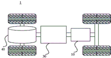
FIG. 1 is a schematic illustration of a vehicle according to an embodiment of the present disclosure;
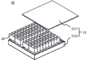
fig. 2 is an exploded view of a battery according to an embodiment of the present disclosure;
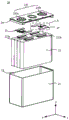
fig. 3 is a schematic view illustrating an exploded structure of a battery cell according to an embodiment of the present disclosure;
FIG. 4 is a schematic structural view of an electrode assembly disclosed in an embodiment of the present application;
FIG. 5 is an enlarged view of portion B of FIG. 4;
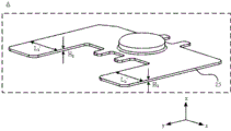
FIG. 6 is an enlarged view of portion A of FIG. 3;
FIG. 7 is a cross-sectional view of an electrode tab according to an embodiment of the present disclosure;
FIG. 8 is a cross-sectional view of an electrode tab disclosed in an embodiment of the present application;
fig. 9 is an enlarged view of portion C in fig. 8.
In the drawings, the drawings are not necessarily to scale.
The reference numerals in the detailed description are as follows:
a vehicle 1;
the battery box comprises a box body 11, a battery monomer 20, an upper box body 111 and a lower box body 112;
a case 21, an electrode assembly 22, an accommodation space 23, an end cap 24, an electrode terminal 241, a positive electrode terminal 241a, a negative electrode terminal 241b, a connection member 25, a first tab 221a, a second tab 222a;
the electrode sheet 221, the current collector 2211, the conductive structure 2212, the main body portion 2213, the tab portion 2214, the bonding area 2215, the protective layer 2216, the active material layer 2217, the conductive layer 2212a, the insulating layer 2212b, the first tab portion 2214a, the second tab portion 2214b, the first bonding area 2215a, and the second bonding area 2215b.
Detailed Description
Embodiments of the present application will be described in further detail with reference to the drawings and examples. The following detailed description of the embodiments and the accompanying drawings are provided to illustrate the principles of the application, but are not intended to limit the scope of the application, i.e., the application is not limited to the described embodiments.
In the description of the present application, it is to be noted that, unless otherwise specified, "a plurality" means two or more; the terms "upper," "lower," "left," "right," "inner," "outer," and the like, indicate an orientation or positional relationship that is merely for convenience in describing the application and to simplify the description, and do not indicate or imply that the referenced devices or elements must be in a particular orientation, constructed and operated in a particular orientation, and therefore should not be construed as limiting the application. Furthermore, the terms "first," "second," "third," and the like are used for descriptive purposes only and are not to be construed as indicating or implying relative importance. "vertical" is not strictly vertical but is within the tolerance of the error. "parallel" is not strictly parallel but is within the tolerance of the error.
The following description is given with the directional terms as they are used in the drawings and not intended to limit the specific structure of the present application. In the description of the present application, it should also be noted that, unless expressly stated or limited otherwise, the terms "mounted," "connected," and "connected" are to be construed broadly and include, for example, fixed and removable connections as well as integral connections; may be directly connected or indirectly connected through an intermediate. The specific meaning of the above terms in the present application can be understood as appropriate by one of ordinary skill in the art.
The term "and/or" in this application is only one kind of association relationship describing the association object, and means that there may be three kinds of relationships, for example, a and/or B, and may mean: a exists alone, A and B exist simultaneously, and B exists alone. In addition, the character "/" in this application generally indicates that the former and latter related objects are in an "or" relationship.
Unless defined otherwise, all technical and scientific terms used herein have the same meaning as commonly understood by one of ordinary skill in the art to which this application belongs; the terminology used in the description of the application in the present application is for the purpose of describing particular embodiments only and is not intended to be limiting of the application; the terms "including" and "having," and any variations thereof, in the description and claims of this application and the description of the above figures are intended to cover non-exclusive inclusions. The terms "first," "second," and the like in the description and claims of this application or in the above-described drawings are used for distinguishing between different elements and not for describing a particular sequential or chronological order.
Reference in the specification to "an embodiment" means that a particular feature, structure, or characteristic described in connection with the embodiment can be included in at least one embodiment of the specification. The appearances of the phrase in various places in the specification are not necessarily all referring to the same embodiment, nor are separate or alternative embodiments mutually exclusive of other embodiments. It is explicitly and implicitly understood by a person skilled in the art that the embodiments described herein can be combined with other embodiments.
In the embodiment of the present application, the battery cell may include a lithium ion secondary battery, a lithium ion primary battery, a lithium sulfur battery, a sodium lithium ion battery, a sodium ion battery, a magnesium ion battery, or the like, which is not limited in the embodiment of the present application. The battery cell may be a cylinder, a flat body, a rectangular parallelepiped, or other shapes, which is not limited in the embodiments of the present application. The battery cells are generally divided into three types in a packaging manner: the single battery of cylindricality battery, square battery monomer and laminate polymer battery monomer, this application embodiment is also not limited to this.
Reference to a battery in embodiments of the present application refers to a single physical module that includes one or more battery cells to provide higher voltage and capacity. For example, the battery referred to in the present application may include a battery module or a battery pack, etc. Batteries generally include a case for enclosing one or more battery cells. The box can avoid liquid or other foreign matters to influence the charging or discharging of battery monomer.
The battery cell may include an electrode assembly composed of a positive electrode tab, a negative electrode tab, and a separator, and an electrolyte. The battery cell mainly depends on metal ions moving between the positive plate and the negative plate to work. The positive plate comprises a positive current collector and a positive active substance layer, wherein the positive active substance layer is coated on the surface of the positive current collector, the current collector which is not coated with the positive active substance layer protrudes out of the current collector which is coated with the positive active substance layer, and the current collector which is not coated with the positive active substance layer is used as a positive pole lug. Taking a lithium ion battery as an example, the material of the positive electrode current collector may be aluminum, and the positive electrode active material may be lithium cobaltate, lithium iron phosphate, ternary lithium, lithium manganate, or the like. The negative plate comprises a negative current collector and a negative active substance layer, the negative active substance layer is coated on the surface of the negative current collector, the current collector which is not coated with the negative active substance layer protrudes out of the current collector which is coated with the negative active substance layer, and the current collector which is not coated with the negative active substance layer is used as a negative electrode tab. The material of the negative electrode current collector may be copper, and the negative electrode active material may be graphite, carbon, silicon, or the like. In order to ensure that the high current can be passed through without fusing, a plurality of positive electrode tabs are stacked together, and a plurality of negative electrode tabs are stacked together. The material of the diaphragm may be polypropylene (PP), polyethylene (PE), or the like. In addition, the electrode assembly may have a winding structure or a lamination structure, and the embodiment of the present application is not limited thereto.
At present, the application of power batteries is more and more extensive from the development of market conditions. The power battery is not only applied to energy storage power supply systems such as hydraulic power, firepower, wind power and solar power stations, but also widely applied to electric vehicles such as electric bicycles, electric motorcycles, electric automobiles and the like, and a plurality of fields such as military equipment and aerospace. With the continuous expansion of the application field of the power battery, the market demand is also continuously expanded.
The development of battery technology needs to consider various design factors, such as energy density, cycle life, discharge capacity, charge and discharge rate, and other performance parameters, and also needs to consider the safety of the battery. For example, with respect to a battery cell, it generally includes an electrode assembly, an electrolyte, a case accommodating the electrode assembly and the electrolyte, and a cap plate mounted on the case, and the cap plate is generally mounted with an electrode terminal for inputting or outputting electric energy. The electrode assembly and the electrode terminal on the cap plate are generally connected indirectly through the connection member, i.e., it is necessary to electrically connect the connection member with the electrode assembly and the electrode terminal, respectively. In consideration of the safety problem of the battery, it is necessary to ensure the overcurrent capability of the tab connected to the connecting member in the electrode assembly and prevent the tab root from being blown out due to excessive current when the battery is short-circuited, thereby preventing the tab root from sparking. Therefore, how to improve the overcurrent capability of the tab and further improve the safety of the battery is a problem to be solved urgently at present.
In view of this, the embodiment of the present application provides an electrode plate, which includes a current collector and a conductive structure, where the conductive structure is welded to a tab portion of the current collector to form a welding region, and the welding region has a dimension L in a second direction, close to one end of the main body portion 1 Greater than a preset threshold that is inversely related to the thickness of the conductive layer of the conductive structure in the third direction. The overcurrent area of the welding area of the conductive structure and the lug part needs to be larger than a certain threshold value so as to ensure that the end part of the welding area is not blown due to overlarge current when the battery is in short circuit, and the end part of the welding area is prevented from sparking to reduce the safety of the battery. In the technical solution of the present application, a dimension L of one end of the land near the body portion in the second direction 1 The thickness of the conductive layer of the conductive structure in the third direction is inversely related to the preset threshold value, so that the overcurrent area of the welding area is ensured to be larger than a certain threshold value, the overcurrent capacity of the welding area is improved, and the end part of the welding area is ensured not to be short-circuited when the battery is short-circuitedCan be burned off, thereby improving the safety of the battery.
The technical scheme described in the embodiment of the application is applicable to various devices using batteries, such as mobile phones, portable devices, notebook computers, battery cars, electric toys, electric tools, electric vehicles, ships, spacecrafts and the like, and the spacecrafts comprise airplanes, rockets, space shuttles, spacecrafts and the like.
It should be understood that the technical solutions described in the embodiments of the present application are not limited to be applied to the above-described devices, but may be applied to all devices using batteries, and for simplicity of description, the following embodiments are all described by taking an electric vehicle as an example.
For example, as shown in fig. 1, which is a schematic structural diagram of a vehicle 1 according to an embodiment of the present disclosure, the vehicle 1 may be a fuel-oil vehicle, a gas-fired vehicle, or a new energy vehicle, and the new energy vehicle may be a pure electric vehicle, a hybrid electric vehicle, or an extended range vehicle. The vehicle 1 may be provided with a motor 40, a controller 30 and a battery 10, the controller 30 being configured to control the battery 10 to supply power to the motor 40. For example, the battery 10 may be provided at the bottom or the head or tail of the vehicle 1. The battery 10 may be used for power supply of the vehicle 1, for example, the battery 10 may be used as an operation power supply of the vehicle 1 for a circuit system of the vehicle 1, for example, for power demand for operation at the start, navigation, and running of the vehicle 1. In another embodiment of the present application, the battery 10 may be used not only as an operation power source of the vehicle 1 but also as a driving power source of the vehicle 1, instead of or in part replacing fuel or natural gas to provide driving power for the vehicle 1.
In order to meet different power usage requirements, the battery 10 may include a plurality of battery cells. For example, fig. 2 is an exploded view of a battery 10 according to an embodiment of the present disclosure, and the battery 10 may include a plurality of battery cells 20. The number of the battery cells 20 may be set to any number according to various power requirements. A plurality of battery cells 20 may be connected in series, parallel, or series-parallel to achieve greater capacity or power. Since the number of the battery cells 20 included in each battery 10 may be large, the battery cells 20 may be arranged in groups for convenience of installation, each group of the battery cells 20 constituting a battery module. The number of the battery cells 20 included in the battery module is not limited and may be set as required. The battery may include a plurality of battery modules that may be connected in series, parallel, or series-parallel.
Alternatively, the battery 10 may also include other structures. For example, the battery 10 may further include a bus member for electrically connecting the plurality of battery cells 20, such as in parallel or in series-parallel. Specifically, the bus member may achieve electrical connection between the battery cells 20 by connecting electrode terminals of the battery cells 20. Further, the bus bar member may be fixed to the electrode terminals of the battery cells 20 by welding. The electric energy of the plurality of battery cells 20 can be further led out through the box body by the conductive mechanism. Alternatively, the current conducting means can also belong to the current collecting part.
The battery 10 may further include a case 11 (or cover), the inside of the case 11 is a hollow structure, and the plurality of battery cells 20 are accommodated in the case 11. As shown in FIG. 2, the housing 11 may comprise two parts, referred to herein as an upper housing 111 and a lower housing 112, respectively, with the upper housing 111 and the lower housing 112 snap together. The shape of the upper case 111 and the lower case 112 may be determined according to the shape of a combination of the plurality of battery cells 20, and at least one of the upper case 111 and the lower case 112 has one opening. For example, the casing 11 may include only one of the upper casing 111 and the lower casing 112 as a hollow rectangular parallelepiped having an opening, and the other as a plate shape to cover the opening. For example, as shown in fig. 2, the lower case 112 is a hollow rectangular parallelepiped with only one surface being an open surface, the upper case 111 is a plate-shaped case, and the upper case 111 covers the open surface of the lower case 112 to form the case 11 having a closed chamber that can accommodate the plurality of battery cells 20.
Alternatively, the box 11 in the embodiment of the present application may further include an upper box 111 and a lower box 112 having other shapes, for example, the upper box 111 and the lower box 112 may be hollow cuboids, only one surface of each of the upper box 111 and the lower box 112 is an opening surface, the opening of the upper box 111 and the opening of the lower box 112 are oppositely disposed, and the upper box 111 and the lower box 112 are buckled to each other to form the box 11 having a closed chamber. The plurality of battery cells 20 are connected in parallel or in series or in a combination of series and parallel to each other and then placed in a case formed by fastening the upper case 111 and the lower case 112.
As shown in fig. 3, which is a schematic structural diagram of a battery cell 20 according to an embodiment of the present disclosure, the battery cell 20 includes one or more electrode assemblies 22, a case 21, and an end cap 24. The housing 21 and end cap 24 form an outer shell or battery compartment. The wall of the case 21 and the end cap 24 are both referred to as the wall of the battery cell 20, wherein for the cuboid battery cell 20, the wall of the case 21 includes a bottom wall and four side walls, and the bottom wall and the four side walls are connected to form a receiving space 23 in which the electrode assembly 22 is placed. The case 21 is determined according to the shape of the one or more electrode assemblies 22 after being combined, for example, the case 21 may be a hollow rectangular parallelepiped, or a square or cylinder, and one of the faces of the case 21 has an opening so that the one or more electrode assemblies 22 can be placed in the case 21. For example, when the housing 21 is a hollow rectangular parallelepiped or cube, one of the planes of the housing 21 is an open plane, that is, the plane has no wall body so that the housing 21 communicates inside and outside. When the housing 21 may be a hollow cylinder, the end surface of the housing 21 is an open surface, i.e., the end surface has no wall body so that the housing 21 communicates with the inside and the outside. The end cap 24 covers an opening of the receiving space 23 and is connected to the case 21 to form a closed cavity in which the electrode assembly 22 is placed. The case 21 is filled with an electrolyte, such as an electrolytic solution.
The battery cell 20 may further include two electrode terminals 241, and the two electrode terminals 241 may be disposed on the end cap 24. The end cap 24 is generally in the shape of a flat plate, and two electrode terminals 241 are fixed on the flat plate surface of the end cap 24, the two electrode terminals 241 being a positive electrode terminal 241a and a negative electrode terminal 241b, respectively. One connecting member 25, which may also be referred to as a current collecting member, is disposed at each of the electrode terminals 241 between the end cap 24 and the electrode assembly 22 to electrically connect the electrode assembly 22 and the electrode terminals 241.
As shown in fig. 3, each electrode assembly 22 has a first tab 221a and a second tab 222a. The first tab 221a and the second tab 222a have opposite polarities. For example, when the first tab 221a is a positive electrode tab, the second tab 222a is a negative electrode tab. The first tabs 221a of the one or more electrode assemblies 22 are connected to one electrode terminal by one connecting member 25, and the second tabs 222a of the one or more electrode assemblies 22 are connected to the other electrode terminal by the other connecting member 25. For example, the positive electrode terminal 241a is connected to a positive electrode tab through one connecting member 25, and the negative electrode terminal 241b is connected to a negative electrode tab through the other connecting member 25.
In the battery cell 20, the electrode assembly 22 may be provided singly or in plurality according to actual use requirements, and as shown in fig. 3, 4 independent electrode assemblies 22 are provided in the battery cell 20.
Fig. 4 shows a schematic view of the structure of an electrode assembly 22 according to an embodiment of the present application. As shown in fig. 4, the electrode assembly 22 is formed by winding the electrode tab 221. The electrode pad 221 includes a current collector 2211 and a conductive structure 2212.
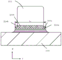
As shown in fig. 5, the current collector 2211 includes a body portion 2213 and a tab portion 2214 arranged in a first direction; the conductive structure 2212 is welded to the tab portion 2214 to form a land 2215, the conductive structure 2212 extends in a direction away from the main body portion 2213, and the land 2215 has a dimension L in a second direction, the dimension L being an end of the land 2215 adjacent to the main body portion 2213 1 Greater than a predetermined threshold that is inversely related to the thickness of the conductive layer 2212a of the conductive structure 2212 in a third direction, the second direction being perpendicular to the first direction and parallel to the tab portion 2214, the third direction being perpendicular to the first and second directions. For example, the first direction is the x-direction in fig. 5, the second direction is the y-direction in fig. 5, and the third direction is the z-direction in fig. 5.
The current collector 2211 of the electrode tab 221 collects the current generated by the active material in the active material layer to form a larger current to be output to the outside, so that the current collector 2211 should be in full contact with the active material and the internal resistance should be as small as possible. The conductive structure 2212 of the electrode tab 221 is electrically connected with the electrode terminal 241 through the connection member 25.
In the embodiment of the present application, the electrode plate 221 includes a current collector 2211 and a conductive structure 2212, the conductive structure 2212 is connected with a tab portion 2214 of the current collector 2211 by welding to form a welding area 2215, and the welding area is formed by the weldingA dimension L1 of the end of the land 2215 proximate to the body portion 2213 in the second direction is greater than a predetermined threshold that is inversely related to the thickness of the conductive layer 2212a of the conductive structure 2212 in the third direction. The current flowing area between the conductive structure 2212 and the welding area 2215 of the tab 2214 needs to be larger than a certain threshold value to ensure that the end of the welding area 2215 is not blown out due to overlarge current when the battery is in short circuit, so as to avoid sparking at the end of the welding area 2215 to reduce the safety of the battery 10. In the solution of the present application, a dimension L of the welding region 2215 in the second direction is close to one end of the main body portion 2213 1 And the preset threshold is greater than the preset threshold, and is inversely related to the thickness of the conductive layer 2212a of the conductive structure 2212 in the third direction, so that the overcurrent area of the welding region 2215 is ensured to be greater than a certain threshold, the overcurrent capacity of the welding region 2215 is improved, the end of the welding region 2215 is ensured not to be blown out when the battery 10 is short-circuited, and the safety of the battery 10 is further improved.
Optionally, in this embodiment of the present application, the preset threshold is Wherein H is 2 Indicates the thickness, L, of the patch at the minimum over-current width of the patch connected to the
 conductive structure 2212 2 Indicates the total width of the connecting surface of the conductive structure 2212 and the interposer at the minimum overcurrent width, H, in the width direction of the interposer 1 Which indicates the total thickness of the conductive layers 2212a in the third direction, C indicates the number of conductive structures 2212 connected to one interposer, and a is a constant not less than 1.
Specifically, the adaptor plate is the connecting member 25 in fig. 3, as shown in fig. 6, H 2 May be such that the connection member 25 has a thickness L in the x direction at which the flow width is minimum 2 May be a total width of the connecting member 25 in the y direction at which the excessive width is minimum, that is, a sum of widths of both sides of the connecting member 25 in fig. 6 at which the excessive width is minimum in the y direction, that is, 2L 2 '. As shown in FIG. 9, H 1 Can be the total thickness of the conductive layer 2212a in the third direction z, i.e. the total thickness H of the conductive layer 2212a of one conductive structure 2212 in the third direction z in fig. 9 1 Is 2H 1 '. It should be understood that during the assembly of the battery cell 20, a plurality of conductive structures 2212 are stacked and then connected to an interposer, and therefore the number C of conductive structures 2212 connected to an interposer is introduced into the formula.
In the embodiment of the present application, in order to ensure that the end of the welding region 2215 is not blown when the battery 10 is short-circuited, it is necessary to ensure that the current flowing area of the welding region 2215 is larger than that of the adapter plate electrically connected thereto, that is, the current flowing area of the adapter plate is larger than that of the welding region 2215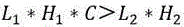 The inequality is transformed to obtain->
 Since a certain processing error exists in the processing of the
 electrode piece 221, a constant not less than 1 is introduced into the inequality, which is the dimension L of the end of the welding region 2215 1 Providing a certain margin, get->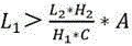 . That is, the dimension L of the
 land 2215 in the second direction near one end of the main body portion 2213 1 Greater than a preset threshold value> Therefore, the total overcurrent area of the
 welding areas 2215 of the plurality of conductive structures 2212 is larger than the overcurrent area of the switching sheets correspondingly connected with the plurality of conductive structures 2212, and the overcurrent capacity of the tab structures formed by laminating the plurality of conductive structures 2212 in the welding areas 2215 is larger than the overcurrent capacity of the corresponding switching sheets, so that the end parts of the welding areas 2215 are prevented from being burnt out when the battery 10 is short-circuited, and the safety of the battery 10 is improved.
Optionally, in this embodiment of the present application, the thickness H at the minimum position of the overcurrent width of the interposer is the thickness H 2 Is 0.8mm, and the total width L of the connecting surface of the adapter sheet and the conductive structure 2212 at the position with the minimum overcurrent width 2 Is 10mm, and the flow area of the adapter plate is 8mm 2 . If the conductive layer 2212a is in the third directionTotal thickness H of 1 1 μm, the number C of conductive structures 2212 connected to one interposer is 80, and the dimension L of the end of land 2215 adjacent to body portion 2213 in the second direction 1 The thickness of the tab structure needs to be larger than 100mm so as to ensure that the overcurrent capacity of the tab structure in a welding area 2215 is larger than that of a corresponding adapter plate.
For another example, the thickness H at the minimum position of the overcurrent width of the interposer 2 Is 0.8mm, and the total width L of the connecting surface of the adapter sheet and the conductive structure 2212 at the position with the minimum overcurrent width 2 20mm, the flow area of the adapter plate is 16mm 2 . If the total thickness H of the conductive layer 2212a in the third direction 1 1 μm, the number C of conductive structures 2212 connected to one interposer is 120, and the dimension L of the bonding pad 2215 near the end of the main body 2213 in the second direction 1 It needs to be larger than 134mm to ensure that the overcurrent capacity of the tab structure in the welding area 2215 is larger than that of the corresponding adapter plate.
It should be understood that the above specific parameter settings are only exemplary illustrations of the embodiments of the application and do not constitute limitations of the application.
Optionally, in the embodiment of the application, 1 ≦ A ≦ 2. In order to ensure that the over-current area of the welding area 2215 is larger than that of the adapter plate electrically connected with the welding area, the constant A is more than or equal to 1; meanwhile, the end dimension L of the welding zone 2215 is based on the structural design of the end cap 24 of the battery cell 20 1 Should not be too large to avoid extruding conductive structure 2212 with the lower plastic under end cap 24. Therefore, the value of the constant A is not too large, and the value range of the constant A is 1 to 2.
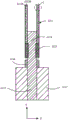
Alternatively, in the embodiment of the present application, as shown in fig. 7, the tab portion 2214 includes a first tab portion 2214a and a second tab portion 2214b, the first tab portion 2214a is disposed between the main body portion 2213 and the second tab portion 2214b, and the size of the first tab portion 2214a is larger than that of the second tab portion 2214b in the second direction y.
In the second direction y, the size of the first tab portion 2214a is larger than that of the second tab portion 2214b, that is, the size of the first tab portion 2214a connected to the main body portion 2213 in the second direction y is larger, so that the connection area between the main body portion 2213 and the tab portion 2214 can be increased, the connection strength between the two portions can be increased, and the size of the second tab portion 2214b is smaller, so that the space occupied by the whole tab portion 2214 can be reduced.
Alternatively, the size of the tab portion 2214 in the second direction y may be continuously and smoothly varied along the first direction x. For example, the tab 2214 may have a triangular structure, a trapezoidal structure, a stepped structure, etc., and fig. 7 illustrates an example in which the tab 2214 has a stepped structure.
Alternatively, in the present embodiment, as shown in fig. 7, the welding region 2215 includes a first welding region 2215a and a second welding region 2215b, the first welding region 2215a is located at the first tab portion 2214a, the second welding region 2215b is located at the second tab portion 2214b, and the size of the first welding region 2215a is larger than that of the second welding region 2215b in the second direction y.
The second welding region 2215b is located on the second electrode tab 2214b with a larger size in the second direction y, so as to ensure that a size L1 of one end, close to the main body portion 2213, of the welding region 2215 formed when the electrode tab 2214 is welded to the conductive structure 2212 in the second direction y can be larger than a preset threshold value, so as to ensure that an overflowing area of an end portion of the welding region 2215 is larger, and improve the safety of the battery 10, and the welding area of the second welding region 2215b and the second electrode tab 2214b is larger, so that the connection strength of the two parts can be improved.
Optionally, in this embodiment of the application, as shown in fig. 8, the conductive structure 2212 further includes an insulating layer 2212b, and the conductive layer 2212a is disposed on an outer surface of the insulating layer 2212 b. When the thickness of the conductive layer 2212a is thick, burrs generated when the conductive layer 2212a is pierced by foreign substances are large, which affects the safety of the battery 10, and thus the insulating layer 2212b is provided, and the conductive layer 2212a is provided on the outer surface of the insulating layer 2212b, so that the thickness of the conductive layer 2212a is controlled while the thickness of the conductive structure 2212 is increased to improve the structural strength of the conductive structure 2212.
Alternatively, in the present embodiment, as shown in fig. 8, the outer surface of the main body portion 2213 is provided with an active material layer 2217. In the battery 10, the active material layer 2217 performs an electrochemical reaction during charging and discharging to convert chemical energy into electric energy.
Optionally, in the embodiment of the present application, as shown in fig. 8, a part of the outer surface of the tab portion 2214 is provided with a protective layer 2216, and the protective layer 2216 is disposed between the conductive structure 2212 and the active material layer 2217 to provide a supporting force for the tab portion 2214, so as to prevent the deformation of the tab portion 2214 from affecting the overcurrent capacity of the pole piece.
Optionally, in this embodiment of the application, the material of the protection layer 2216 is an insulating material, so as to prevent the protection layer 2216 from conducting electricity to affect a current flowing path in the electrode pad 221, and ensure safety of electrical connection of the electrode pad 221.
Alternatively, the insulating material may include at least one of alumina and aluminum oxyhydroxide.
Alternatively, the protection layer 2216 may be disposed on the outer surface of the tab portion 2214 by a coating or plating process.
The embodiment of the present application also provides an electrode assembly 22, and the electrode assembly 22 may include the electrode tab 221 in the foregoing embodiments.
The embodiment of the present application also provides a battery cell 20, and the battery cell 20 may include a case, an end cap, and the electrode assembly 22 in the foregoing embodiments. The case has an opening for accommodating the electrode assembly 22; the end cap is used for closing the opening.
The embodiment of the present application also provides a battery 10, and the battery 10 may include the battery cell 20 in the foregoing embodiments. In some embodiments, the battery 10 may further include other structures such as a box body and a bus bar, which are not described in detail herein.
The embodiment of the present application also provides a power consumption device, which may include the battery 10 in the foregoing embodiment. Optionally, the electric device may be a vehicle 1, a ship, a spacecraft, or the like, but the embodiment of the present application is not limited thereto.
While the application has been described with reference to a preferred embodiment, various modifications may be made and equivalents may be substituted for elements thereof without departing from the scope of the application. In particular, the technical features mentioned in the embodiments can be combined in any way as long as there is no structural conflict. The present application is not intended to be limited to the particular embodiments disclosed herein but is to cover all embodiments that may fall within the scope of the appended claims.
Claims (12)
1. An electrode sheet, comprising:
a current collector (2211), the current collector (2211) comprising a body portion (2213) and a tab portion (2214) disposed along a first direction (x);
a conductive structure (2212), the conductive structure (2212) being solder-connected to the tab portion (2214) to form a land (2215), the conductive structure (2212) extending in a direction away from the main body portion (2213), the land (2215) being adjacent to a dimension L of an end of the main body portion (2213) in a second direction (y) 1 Is greater than a preset threshold value, which is inversely related to the thickness of the conductive layer (2212 a) of the conductive structure (2212) in the third direction (z), the preset threshold value being ;
;
Wherein H 2 Represents the thickness, L, of the patch at the minimum of the overcurrent width in connection with said conductive structure (2212) 2 Represents the total width H of the connecting surface of the conductive structure (2212) and the adapter sheet at the position with the minimum overcurrent width in the width direction of the adapter sheet 1 Represents the total thickness of the conductive layers (2212 a) in the third direction (z), C represents the number of the conductive structures (2212) connected to one of the interposer, a is a constant no less than 1, the second direction (y) is perpendicular to the first direction (x) and parallel to the pole ear (2214), and the third direction (z) is perpendicular to the first direction (x) and the second direction (y).
2. The electrode piece of claim 1, wherein A is 1. Ltoreq. A.ltoreq.2.
3. The electrode tab of claim 1, wherein the tab portion (2214) comprises a first tab portion (2214 a) and a second tab portion (2214 b), the first tab portion (2214 a) being disposed between the main body portion (2213) and the second tab portion (2214 b), the first tab portion (2214 a) having a dimension greater than a dimension of the second tab portion (2214 b) in the second direction (y).
4. The electrode pad of claim 3, wherein the weld zone (2215) comprises a first weld zone (2215 a) and a second weld zone (2215 b), the first weld zone (2215 a) being located at the first pole ear (2214 a), the second weld zone (2215 b) being located at the second pole ear (2214 b), the first weld zone (2215 a) having a larger size than the second weld zone (2215 b) in the second direction (y).
5. The electrode tab of claim 1, wherein the conductive structure (2212) further comprises an insulating layer (2212 b), and the conductive layer (2212 a) is disposed on an outer surface of the insulating layer (2212 b).
6. The electrode tab as claimed in claim 1, wherein the main body portion (2213) is provided with an active material layer (2217) on its outer surface.
7. The electrode tab of claim 6, wherein a portion of the outer surface of the tab portion (2214) is provided with a protective layer (2216), the protective layer (2216) being disposed between the conductive structure (2212) and the active material layer (2217).
8. The electrode pad of claim 7, wherein the material of the protective layer (2216) is an insulating material.
9. An electrode assembly, comprising: the electrode tab according to any one of claims 1 to 8.
10. A battery cell, comprising:
the electrode assembly of claim 9;
a case having an opening for receiving the electrode assembly;
an end cap for closing the opening.
11. A battery comprising the battery cell of claim 10.
12. An electrical consumer, characterized in that it comprises a battery according to claim 11 for providing electrical energy.
Priority Applications (1)
| Application Number | Priority Date | Filing Date | Title |
|---|---|---|---|
| CN202211374725.8A CN115425372B (en) | 2022-11-04 | 2022-11-04 | Electrode pole piece, electrode component, battery monomer, battery and consumer |
Applications Claiming Priority (1)
| Application Number | Priority Date | Filing Date | Title |
|---|---|---|---|
| CN202211374725.8A CN115425372B (en) | 2022-11-04 | 2022-11-04 | Electrode pole piece, electrode component, battery monomer, battery and consumer |
Publications (2)
| Publication Number | Publication Date |
|---|---|
| CN115425372A CN115425372A (en) | 2022-12-02 |
| CN115425372B true CN115425372B (en) | 2023-04-14 |
Family
ID=84207577
Family Applications (1)
| Application Number | Title | Priority Date | Filing Date |
|---|---|---|---|
| CN202211374725.8A Active CN115425372B (en) | 2022-11-04 | 2022-11-04 | Electrode pole piece, electrode component, battery monomer, battery and consumer |
Country Status (1)
| Country | Link |
|---|---|
| CN (1) | CN115425372B (en) |
Families Citing this family (2)
| Publication number | Priority date | Publication date | Assignee | Title |
|---|---|---|---|---|
| CN117239058B (en) * | 2023-11-13 | 2024-03-01 | 珠海冠宇电池股份有限公司 | Pole piece, battery cell and battery |
| CN117691267B (en) * | 2024-02-04 | 2024-04-12 | 蜂巢能源科技股份有限公司 | Battery and battery pack |
Family Cites Families (8)
| Publication number | Priority date | Publication date | Assignee | Title |
|---|---|---|---|---|
| CN106992313B (en) * | 2016-01-20 | 2023-04-07 | 宁德新能源科技有限公司 | Secondary battery |
| CN108598491B (en) * | 2018-06-22 | 2020-10-02 | 宁德时代新能源科技股份有限公司 | Secondary battery and pole piece thereof |
| CN209087968U (en) * | 2018-08-02 | 2019-07-09 | 宁德时代新能源科技股份有限公司 | Electrode member, electrode assembly and secondary cell |
| CN209183628U (en) * | 2018-10-11 | 2019-07-30 | 宁德时代新能源科技股份有限公司 | Secondary cell and its pole piece |
| CN209747632U (en) * | 2019-05-13 | 2019-12-06 | 宁德时代新能源科技股份有限公司 | Secondary battery |
| CN114975864A (en) * | 2021-02-23 | 2022-08-30 | 北京小米移动软件有限公司 | Pole piece, electric core structure, lithium battery and electronic equipment |
| CN216354652U (en) * | 2021-11-30 | 2022-04-19 | 宁德时代新能源科技股份有限公司 | Electrode assembly and power battery |
| CN114566768A (en) * | 2022-02-10 | 2022-05-31 | 东莞新能安科技有限公司 | Pole piece, electrochemical device and electronic equipment |
-
2022
- 2022-11-04 CN CN202211374725.8A patent/CN115425372B/en active Active
Also Published As
| Publication number | Publication date |
|---|---|
| CN115425372A (en) | 2022-12-02 |
Similar Documents
| Publication | Publication Date | Title |
|---|---|---|
| CN115425372B (en) | Electrode pole piece, electrode component, battery monomer, battery and consumer | |
| US20230123940A1 (en) | Battery cell, battery and power consuming device | |
| CN213692108U (en) | Electrode assembly, battery cell, battery, and power consumption device | |
| CN216085053U (en) | Battery and electric equipment | |
| US11757161B2 (en) | Battery cell, battery and electricity consuming device | |
| US20230216154A1 (en) | Current collecting member, battery cell, battery, and power consuming device | |
| US20230395952A1 (en) | Battery cell, battery and electrical device | |
| US20230327264A1 (en) | Battery module, battery, power consumption device, and method and device for producing battery | |
| US20230268586A1 (en) | Battery, power consumption device, and method and device for producing battery | |
| CN217768705U (en) | Pole piece structure, electric core subassembly, battery monomer, battery and power consumption device | |
| US20230087166A1 (en) | Electrode assembly, battery cell, battery and electrical device | |
| CN217788451U (en) | Pole piece, electrode subassembly, battery monomer, battery and consumer | |
| CN217134554U (en) | Battery and electric equipment | |
| US20220247043A1 (en) | Battery cell, battery, power consumption device and battery cell manufaturing method and device | |
| EP4266464A1 (en) | Battery, electric device, and method and device for preparing battery | |
| CN115968515A (en) | Battery, electric equipment, method and equipment for preparing battery | |
| CN116470241A (en) | Electrode assembly, battery cell, battery and electric equipment | |
| KR20220151694A (en) | End cover assembly, battery cell, method and equipment for manufacturing battery and battery cell | |
| CN217361642U (en) | Electrode assembly, battery cell, battery and electric equipment | |
| CN220400841U (en) | Battery connection tab, battery and electricity utilization device | |
| US20230275296A1 (en) | Battery, power consumption device, and method and device for producing battery | |
| WO2023065366A1 (en) | Battery, electric device, method for preparing battery cell, and device | |
| CN218414960U (en) | Electrode assembly, battery cell, battery and power consumption device | |
| CN215496869U (en) | End cover assembly, battery monomer, battery and consumer | |
| CN220672722U (en) | Battery cell, battery and electricity utilization device |
Legal Events
| Date | Code | Title | Description |
|---|---|---|---|
| PB01 | Publication | ||
| PB01 | Publication | ||
| SE01 | Entry into force of request for substantive examination | ||
| SE01 | Entry into force of request for substantive examination | ||
| GR01 | Patent grant | ||
| GR01 | Patent grant |