EP4421941A1 - Cell winding process, cell winding apparatus, cell, battery, and electric apparatus - Google Patents
Cell winding process, cell winding apparatus, cell, battery, and electric apparatus Download PDFInfo
- Publication number
- EP4421941A1 EP4421941A1 EP22891841.3A EP22891841A EP4421941A1 EP 4421941 A1 EP4421941 A1 EP 4421941A1 EP 22891841 A EP22891841 A EP 22891841A EP 4421941 A1 EP4421941 A1 EP 4421941A1
- Authority
- EP
- European Patent Office
- Prior art keywords
- cell
- winding
- electrode plate
- separator layer
- heating
- Prior art date
- Legal status (The legal status is an assumption and is not a legal conclusion. Google has not performed a legal analysis and makes no representation as to the accuracy of the status listed.)
- Pending
Links
Images


Classifications
-
- H—ELECTRICITY
- H01—ELECTRIC ELEMENTS
- H01M—PROCESSES OR MEANS, e.g. BATTERIES, FOR THE DIRECT CONVERSION OF CHEMICAL ENERGY INTO ELECTRICAL ENERGY
- H01M10/00—Secondary cells; Manufacture thereof
- H01M10/04—Construction or manufacture in general
- H01M10/0404—Machines for assembling batteries
- H01M10/0409—Machines for assembling batteries for cells with wound electrodes
-
- H—ELECTRICITY
- H01—ELECTRIC ELEMENTS
- H01M—PROCESSES OR MEANS, e.g. BATTERIES, FOR THE DIRECT CONVERSION OF CHEMICAL ENERGY INTO ELECTRICAL ENERGY
- H01M10/00—Secondary cells; Manufacture thereof
- H01M10/05—Accumulators with non-aqueous electrolyte
- H01M10/058—Construction or manufacture
- H01M10/0587—Construction or manufacture of accumulators having only wound construction elements, i.e. wound positive electrodes, wound negative electrodes and wound separators
-
- B—PERFORMING OPERATIONS; TRANSPORTING
- B60—VEHICLES IN GENERAL
- B60L—PROPULSION OF ELECTRICALLY-PROPELLED VEHICLES; SUPPLYING ELECTRIC POWER FOR AUXILIARY EQUIPMENT OF ELECTRICALLY-PROPELLED VEHICLES; ELECTRODYNAMIC BRAKE SYSTEMS FOR VEHICLES IN GENERAL; MAGNETIC SUSPENSION OR LEVITATION FOR VEHICLES; MONITORING OPERATING VARIABLES OF ELECTRICALLY-PROPELLED VEHICLES; ELECTRIC SAFETY DEVICES FOR ELECTRICALLY-PROPELLED VEHICLES
- B60L50/00—Electric propulsion with power supplied within the vehicle
- B60L50/50—Electric propulsion with power supplied within the vehicle using propulsion power supplied by batteries or fuel cells
- B60L50/60—Electric propulsion with power supplied within the vehicle using propulsion power supplied by batteries or fuel cells using power supplied by batteries
- B60L50/66—Arrangements of batteries
-
- H—ELECTRICITY
- H01—ELECTRIC ELEMENTS
- H01M—PROCESSES OR MEANS, e.g. BATTERIES, FOR THE DIRECT CONVERSION OF CHEMICAL ENERGY INTO ELECTRICAL ENERGY
- H01M2220/00—Batteries for particular applications
- H01M2220/20—Batteries in motive systems, e.g. vehicle, ship, plane
-
- Y—GENERAL TAGGING OF NEW TECHNOLOGICAL DEVELOPMENTS; GENERAL TAGGING OF CROSS-SECTIONAL TECHNOLOGIES SPANNING OVER SEVERAL SECTIONS OF THE IPC; TECHNICAL SUBJECTS COVERED BY FORMER USPC CROSS-REFERENCE ART COLLECTIONS [XRACs] AND DIGESTS
- Y02—TECHNOLOGIES OR APPLICATIONS FOR MITIGATION OR ADAPTATION AGAINST CLIMATE CHANGE
- Y02E—REDUCTION OF GREENHOUSE GAS [GHG] EMISSIONS, RELATED TO ENERGY GENERATION, TRANSMISSION OR DISTRIBUTION
- Y02E60/00—Enabling technologies; Technologies with a potential or indirect contribution to GHG emissions mitigation
- Y02E60/10—Energy storage using batteries
-
- Y—GENERAL TAGGING OF NEW TECHNOLOGICAL DEVELOPMENTS; GENERAL TAGGING OF CROSS-SECTIONAL TECHNOLOGIES SPANNING OVER SEVERAL SECTIONS OF THE IPC; TECHNICAL SUBJECTS COVERED BY FORMER USPC CROSS-REFERENCE ART COLLECTIONS [XRACs] AND DIGESTS
- Y02—TECHNOLOGIES OR APPLICATIONS FOR MITIGATION OR ADAPTATION AGAINST CLIMATE CHANGE
- Y02P—CLIMATE CHANGE MITIGATION TECHNOLOGIES IN THE PRODUCTION OR PROCESSING OF GOODS
- Y02P70/00—Climate change mitigation technologies in the production process for final industrial or consumer products
- Y02P70/50—Manufacturing or production processes characterised by the final manufactured product
Definitions
- the present application relates to the technical field of lithium-ion batteries, and in particular, to a cell winding process, a cell winding device, a cell, a battery, and a power consuming device.
- Lithium-ion batteries are increasingly being used in the market due to their advantages of high energy density, high output power, long cycle life, low environmental pollution, etc.
- the lithium-ion battery includes a wound battery, which is a battery composed of cells formed in a wound manner. Compared with a flat battery, the wound battery is formed by winding electrode plates with a thickness of only about 1 mm at a high pressure. By special technological means, the battery has the characteristics of super high-rate discharge capacity, excellent high- and low-temperature performance, stable high output voltage, higher energy density, etc.
- the present application provides a cell winding process, including:
- the separator layer is located between the cathode electrode plate and the anode electrode plate, the heated regions on the two surfaces of the separator layer that respectively face the cathode electrode plate and the anode electrode plate are heated, so that a polycarbosilane (PCS) polymer of the separator layer is melted and then wound, and the cathode electrode plate and the anode electrode plate can thus be closely bonded to the separator layer.
- PCS polycarbosilane
- the cathode electrode plate can be bonded and fixed to the anode electrode plate by means of the structure of the separator layer itself, without the need to add other bonding structures.
- This can simplify the structure of the cell to the greatest extent and reduce the thickness of the wound cell and the volume of the cell.
- each heated region is located on a side edge of the separator layer parallel to a winding direction, and the width of the heated region ranges from 2 mm to 4 mm.
- a heating width is less than 2 mm, a bonding width is too small, resulting in a poor effect of bonding the cathode electrode plate and the anode electrode plate to the separator layer, making it impossible to fix the cathode electrode plate and the anode electrode plate.
- the heating width is greater than 4 mm, intercalation and deintercalation of lithium ions in a bonding region are affected, thus deteriorating the performance of the cell.
- each heated region is located on a side edge of the separator layer parallel to a winding direction, and the length of the heated region is at least three turns.
- a heating temperature of the heating portion is 90°C to 130°C.
- the heating temperature is greater than 130°C, the melting of the separator layer is likely to lead to blockage of original micropores in the separator layer, affecting the transfer of lithium ions during charging and discharging, and thus deteriorating resistance, capacity, cycle and other properties of the battery. If the heating temperature is less than 90°C, the PCS polymer of the separator layer cannot be melted, and a bonding and fixing effect cannot be achieved.
- the method further includes: a pre-pressing step in which a cell is obtained after the winding step is completed, the winding needle is pulled out from the cell, and a pressure is applied for pre-pressing to shape and bind the electrode plates of the cell.
- the multiple layers of electrode plates will be retracted due to stress release.
- a proper pressure is applied to the wound cell for pre-pressing, which can achieve a shaping and binding effect and improve the performance of the cell.
- the winding device includes a plurality of winding rollers configured to transport the separator layer, and all the winding rollers are arranged spaced apart from each other in a conveying direction of the separator layer.
- the separator layer, the cathode electrode plate and the anode electrode plate can be conveyed and transferred by means of the plurality of winding rollers.
- the heating portion is arranged on one of the plurality of winding rollers that is close to the winding needle.
- the heating portion is arranged on the winding roller close to the winding needle, so that the heating temperature at the separator layer can be ensured, and the failure of bonding and fixation caused by cooling can be avoided.
- the present application provides a cell winding device configured to operate the cell winding process described above, the cell winding device including a winding device configured to wind a cell.
- a heating portion is arranged on the winding device, to heat heated regions on two surfaces of a separator layer that are respectively attached to a cathode electrode plate and an anode electrode plate.
- the heating portion is located at an edge of the separator layer parallel to a winding direction, and has a heating width ranging from 2 mm to 4 mm.
- the heating portion is located at an edge of the separator layer parallel to a winding direction, and has a heating length of at least three turns.
- a heating temperature of the heating portion ranges from 90°C to 130°C.
- the winding device includes a plurality of winding rollers configured to transport the separator layer, and all the winding rollers are arranged spaced apart from each other in a conveying direction of the separator layer.
- the heating portion is arranged on one of the plurality of winding rollers that is close to the winding needle.
- the present application provides a cell, which is prepared by means of a cell winding process described above.
- the present application provides a battery, including a housing, and a cell described above.
- the cell is arranged in the housing.
- the present application provides a power consuming device, including a power consuming body, and a battery described above.
- the separator layer is heated by the heating portion, such that the PCS polymer of the separator layer is melted at a high temperature, to bond the cathode electrode plate to the anode electrode plate, and the cathode electrode plate is thus closely bonded and fixed to the anode electrode plate, thereby preventing the electrode plates from being retracted due to stress release after winding, which otherwise results in a gap. Therefore, the problem of lithium precipitation on an anode surface caused by a too long lithium ion transport path during charging and discharging can be prevented, and the safety performance of the battery can be further improved.
- a and/or B may include: only A exists, both A and B exist, and only B exists.
- the character "/" herein generally indicates an "or" relationship between the associated objects.
- a plurality of means two or more (including two), similarly the term “a plurality of groups” means two or more groups (including two groups), and the term “a plurality of pieces” means two or more pieces (including two pieces).
- the technical terms such as “mount”, “connected”, “connect”, and “fix” should be understood in a broad sense, for example, they may be a fixed connection, a detachable connection, or an integrated connection; may be a mechanical connection or an electrical connection; or may be a direct connection or an indirect connection by means of an intermediate medium, or may be internal communication between two elements or interaction between the two elements.
- the specific meanings of the above terms in the embodiments of the present application can be understood according to specific situations.
- lithium-ion batteries are widely used in electric vehicles and consumer electronics because of their advantages of high energy density, high output power, long cycle life, low environmental pollution, etc.
- the market demand for the lithium-ion batteries is also expanding.
- a process of producing a lithium-ion battery generally includes the following steps.
- a first step of preparing electrode slurries mainly an electrode active material, a binder, a solvent, etc. are mixed together and are fully stirred and dispersed to form each slurry.
- the slurries prepared in the first step are each uniformly coated onto a current collector (an aluminum foil, a copper foil, etc.) with a specified thickness, and the solvent is dried.
- a third step of punching electrode plates the electrode plates manufactured in the previous step are punched into specified sizes and shapes.
- a cathode electrode plate, an anode electrode plate, and a separator are assembled together, and a cell is formed after gluing is completed.
- a fifth step of assembling a pouch battery the cell produced in the previous step is mounted into a punched aluminum-plastic film, and top sealing, side sealing, etc. are completed (with an electrolyte injection port reserved) to form a pouch battery without electrolyte injection.
- a sixth step of injecting an electrolyte a specified amount of electrolyte is injected into the pouch cell.
- a gas inside the cell is pumped out in a vacuum environment to complete the sealing.
- a winding step is further provided in the above stacking step for the wound battery.
- the cathode electrode plate and the anode electrode plate are attached to the separator, and winding is then performed to form the wound battery. Next, assembly is performed.
- the wound battery is made by winding electrode plates with a thickness of only about 1 millimeter (mm) at a high pressure, and is made by special technological means. Therefore, compared with the flat plate battery, the wound battery has the following characteristics: 1. super high-rate discharge capacity; 2. excellent high- and low-temperature performance; 3. stable high output voltage; 4. higher energy density; 5. excellent anti-vibration performance; and 6. capability of being charged quickly and longer service life. As a result, wound batteries have been increasingly widely used in the market.
- the separator layer is provided with a PCS polymer, which is specifically composed of PVDF, that is, polyvinylidene fluoride.
- PVDF polyvinylidene fluoride
- This component melts at a certain temperature, and after melting, the separator layer will have a bonding effect.
- the applicant has thought that if the PCS polymer of the separator layer is melted under a specific condition, the cathode electrode plate and the anode electrode plate can be bonded and fixed to each other by means of the polymer itself, which not only solves the bonding problem between the cathode electrode plate and the anode electrode plate, but also simplifies the structure of the wound battery without adding an external structure, thereby enabling the wound battery to have a smaller volume after being pressed.
- the applicant in order to solve the problem of lithium precipitation caused by generation of a gap between bent portions of the cathode electrode plate and the anode electrode plate while reducing the volume of the wound battery, the applicant has designed a cell winding process through in-depth research, which reduces the volume of the wound battery and can solve the problem of lithium precipitation and short circuit of the wound battery by means of the structure of the separator layer itself and by special technological means.
- the cell disclosed in the embodiment of the present application may be used in, but not limited to, a power consuming device such as a vehicle, a ship or an aircraft.
- a power supply system of the power consuming device may be composed of the cell, the battery, etc. disclosed in the present application. This contributes to bonding and fixing the cathode electrode plate to the anode electrode plate, prevents lithium precipitation caused by the occurrence of a gap between the cathode electrode plate and the anode electrode plate, prevents lithium precipitation on an anode surface caused by a too long lithium ion transport path during charging and discharging, and further improves the safety performance of the battery.
- An embodiment of the present application provides a power consuming device using a battery as a power supply.
- the power consuming device may be, but is not limited to, a mobile phone, a tablet, a notebook computer, an electric toy, an electric tool, a battery cart, an electric vehicle, a ship, a spacecraft, etc.
- the electric toy may include a stationary or mobile electric toy, such as a game console, an electric vehicle toy, an electric ship toy and an electric airplane toy.
- the spacecraft may include an airplane, a rocket, a space shuttle, a spaceship, etc.
- FIG. 1 is a schematic structural diagram of a vehicle 1000 according to some embodiments of the present application.
- the vehicle 1000 may be a fuel vehicle, a gas vehicle, or a new energy vehicle.
- the new energy vehicle may be a battery electric vehicle, a hybrid electric vehicle, an extended-range vehicle, etc.
- a battery 100 is provided inside the vehicle 1000, and the battery 100 may be arranged at a bottom, a head or a tail of the vehicle 1000.
- the battery 100 may be configured to supply power to the vehicle 1000.
- the battery 100 may be used as a power supply for operating the vehicle 1000.
- the vehicle 1000 may further include a controller 200 and a motor 300.
- the controller 200 is configured to control the battery 100 to supply power to the motor 300, for example, to meet working power requirements during starting, navigation and traveling of the vehicle 1000.
- the battery 100 may not only serve as a power supply for operating the vehicle 1000, but also serve as a power supply for driving the vehicle 1000, in place of or partially in place of fuel or natural gas, to supply driving power to the vehicle 1000.
- FIG. 2 is a schematic structural diagram of a battery according to an embodiment of the present application.
- the battery 100 includes a case 10 and a cell 20.
- the cell 20 is accommodated in the case 10.
- the case 10 is configured to provide an accommodating space for the cell 20, and the case 10 may be of various structures.
- the case 10 may include a first portion 11 and a second portion 12.
- the first portion 11 and the second portion 12 are fitted to each other in a covering manner.
- the first portion 11 and the second portion 12 jointly define an accommodating space for accommodating the cell 20.
- the second portion 12 may be of a hollow structure with one end open, the first portion 11 may be of a plate-like structure, and the first portion 11 covers an open side of the second portion 12 such that the first portion 11 and the second portion 12 jointly define the accommodating space.
- the first portion 11 and the second portion 12 each may be of a hollow structure with one side open, and the open side of the first portion 11 covers the open side of the second portion 12.
- the case 10 formed by the first portion 11 and the second portion 12 may be in various shapes such as a cylinder and a cuboid.
- a plurality of cells 20 may be provided.
- the plurality of cells 20 may be connected in series or in parallel or in series-parallel.
- the series-parallel connection means that some of the plurality of cells 20 are in series connection and some are in parallel connection.
- the plurality of cells 20 may be directly connected to each other in series or in parallel or in series-parallel, and then a whole composed of the plurality of cells 20 is accommodated in the case 10.
- the battery 100 may also be accommodated in the case 10 as a whole that is formed by firstly connecting a plurality of cells 20 in series or in parallel or in series-parallel to form a plurality of battery modules, and then connecting the plurality of battery modules in series or in parallel or in series-parallel.
- the battery 100 may further include other structures.
- the battery 100 may further include a bus component configured to implement electrical connections between the plurality of cells 20.
- FIG. 3 is a schematic structural diagram of a cell according to an embodiment of the present application.
- Each cell 20 may be a secondary battery or a primary battery; or may be a lithium-sulfur battery, a sodium-ion battery, or a magnesium-ion battery, but is not limited thereto.
- the cell 20 may be in a cylindrical shape, a flat shape, a cuboid shape, or another shape. Specifically, the cell 20 refers to a smallest unit of a battery.
- the cell 20 includes an end cap 21, a housing 22, a cell assembly 23 and other functional components.
- the end cap 21 refers to a component that covers an opening of the housing 22 to isolate an internal environment of the cell 20 from an external environment.
- the end cap 21 may be shaped to adapt to the shape of the housing 22 so as to mate with the housing 22.
- the end cap 21 may be made of a material (for example, an aluminum alloy) with a certain hardness and strength. In this way, the end cap 21 is less prone to deformation when subjected to compression and collision, so that the cell 20 can have a higher structural strength and the safety performance can also be improved.
- Functional components, such as electrode terminals 21a may be arranged on the end cap 21.
- the electrode terminals 21a may be configured to be electrically connected to the cell assembly 23, so as to output or input electric energy for the cell 20.
- a pressure relief mechanism which is configured to release an internal pressure when the internal pressure or temperature of the cell 20 reaches a threshold, may be further provided on the end cap 21.
- the end cap 21 may be made of various materials, such as copper, iron, aluminum, stainless steel, an aluminum alloy, and plastic, which is not specifically limited in the embodiments of the present application.
- an insulating member may be further provided on an inner side of the end cap 21. The insulating member may be used to isolate electrical connection components in the housing 22 from the end cap 21 in order to reduce the risk of short circuit.
- the insulating member may be made of plastic, rubber, etc.
- the housing 22 is an assembly configured to cooperate with the end cap 21 to form the internal environment of the cell 20.
- the formed internal environment may be used to accommodate the cell assembly 23, an electrolyte, and other components.
- the housing 22 and the end cap 21 may be separate components, and the housing 22 may be provided with an opening, at which the end cap 21 covers the opening to form the internal environment of the cell 20.
- the end cap 21 and the housing 22 may also be integrated with each other. Specifically, the end cap 21 and the housing 22 may form a common connection face before other components are inserted into the housing. When the interior of the housing 22 needs to be packaged, the end cap 21 then covers the housing 22.
- the housing 22 may have various shapes and various sizes, for example, in the shape of a cuboid, a cylinder, a hexagonal prism, etc. Specifically, the housing 22 may be shaped depending on the specific shape and size of the cell assembly 23.
- the housing 22 may be made of various materials, such as copper, iron, aluminum, stainless steel, an aluminum alloy, and plastic, which is not specially limited in the embodiments of the present application.
- the cell assembly 23 is a component in the cell 20 where an electrochemical reaction takes place.
- the housing 22 may contain one or more cell assemblies 23.
- the cell assembly 23 is mainly formed by winding or stacking a cathode electrode plate and an anode electrode plate, and is typically provided with a separator between the cathode electrode plate and the anode electrode plate. Portions of the cathode electrode plate and the anode electrode plate that each have an active material form a main body portion of the cell assembly 23, and portions of the cathode electrode plate and the anode electrode plate that have no active material each form a tab 23a.
- a cathode tab and an anode tab may be located at one end of the main body portion together or at two ends of the main body portion respectively.
- an embodiment of the present application provides a cell winding process, including the following steps.
- a rolling-up step S10 starting ends of a separator layer 24, a cathode electrode plate 25, and an anode electrode plate 26 are fixed to a winding device 27 configured to wind a cell, and the separator layer 24 is placed between the cathode electrode plate 25 and the anode electrode plate 26.
- a heating portion 271 is arranged on the winding device 27, and the heating portion 271 heats heated regions 241 on two surfaces of the separator layer 24 that are respectively attached to the cathode electrode plate 25 and the anode electrode plate 26.
- the separator layer 24 is located between the cathode electrode plate 25 and the anode electrode plate 26, the heated regions 241 on the two surfaces of the separator layer 24 that respectively face the cathode electrode plate 25 and the anode electrode plate 26 are heated, so that a PCS polymer of the separator layer is melted and then wound, and the cathode electrode plate 25 and the anode electrode plate 26 can thus be closely bonded to the separator layer 24.
- the heating portion 271 may be provided as a heating sheet, which is attached to the separator layer 24 by means of the winding device 27, so as to heat the separator layer 24. It may be understood that the heating portion 271 may alternatively be provided as another heating structure, such as a heating tube and an infrared heater, which is not described in detail herein.
- the heated region 241 is located on a side edge of the separator layer 24 parallel to a winding direction, and the width of the heated region 241 ranges from 2 mm to 4 mm.
- the heated region 241 is at an edge of the separator layer 24 and extends inwardly from the edge by 2 mm to 4 mm.
- two heated regions 241 are generally included, and are respectively located on two side edges of the separator layer 24, and each have a width of 2 mm to 4 mm. That is, a left edge and a right edge of the separator layer 24 are both heated, so that the cathode electrode plate 25 and the anode electrode plate 26 can be attached to the separator layer 24 more closely.
- the width of the heated region 241 is less than 2 mm, a bonding width is too small, resulting in a poor effect of bonding the cathode electrode plate 25 and the anode electrode plate 26 to the separator layer 24, making it impossible to fix the cathode electrode plate 25 and the anode electrode plate 26. If the width of the heated region 241 is greater than 4 mm, intercalation and deintercalation of lithium ions in a bonding region are affected, thus deteriorating the performance of the cell.
- the length of the heated region 241 is at least three turns. That is, the heated region 241 on the separator layer 24 should enable the cathode electrode plate 25, the separator layer 24 and the anode electrode plate 26 to be jointly wound for at least three turns. If the length of the heated region 241 is less than three turns, the cathode electrode plate 25 and the anode electrode plate 26 cannot be effectively bonded to the separator layer, and a fixing effect cannot be achieved.
- a heating temperature of the heating portion 271 ranges from 90°C to 130°C.
- the separator layer 24 is of a fibrous structure, several small through-holes are distributed in the separator layer, and the through-holes provide channels for transfer of lithium ions. If the heating temperature is greater than 130°C, the melting of the separator layer 24 is likely to lead to blockage of original micropores in the separator layer, affecting the transfer of lithium ions during charging and discharging, and thus deteriorating resistance, capacity, cycle and other properties of the battery. If the heating temperature is less than 90°C, the PCS polymer of the separator layer 24 cannot be melted, and a bonding and fixing effect cannot be achieved.
- a winding needle 272 is arranged on the winding device 27, and the heated separator layer 24, the cathode electrode plate 25, and the anode electrode plate 26 are wound by means of the winding needle 272.
- a cell is obtained after the winding step is completed, the winding needle 272 is pulled out from the cell, and a pressure is applied for pre-pressing to shape and bind the electrode plates of the cell.
- the multiple layers of electrode plates will be retracted due to stress release.
- a proper pressure is applied to the wound cell for pre-pressing, which can achieve a shaping and binding effect and improve the performance of the cell.
- the winding device 27 in the aforementioned cell winding process includes a plurality of winding rollers 273 configured to convey the separator layer, and all the winding rollers 273 are arranged spaced apart from each other in a conveying direction of the separator layer 24.
- the separator layer 24, the cathode electrode plate 25, and the anode electrode plate 26 respectively correspond to the plurality of winding rollers 273. Since the separator layer 24, the cathode electrode plate 25, and the anode electrode plate 26 each have a large length before winding, it is necessary to convey and transfer the separator layer 24, the cathode electrode plate 25, and the anode electrode plate 26 by means of the plurality of winding rollers 273.
- the heating portion 271 is arranged on one winding roller 273 of the plurality of winding rollers 273 that is close to the winding needle 272. That is, the heating portion 271 is arranged on the winding roller 273 closest to the winding needle 272, so that the failure to fix the heated separator layer 24 due to cooling during conveying can be prevented.
- the present application further provides a cell winding device configured to operate the aforementioned cell winding process, the cell winding device including a winding device 27 configured to wind a cell.
- a heating portion 271 is arranged on the winding device 27, to heat heated regions 241 on two surfaces of the separator layer 24 that are respectively attached to the cathode electrode plate 25 and the anode electrode plate 26.
- the separator layer 24 is placed between the cathode electrode plate 25 and the anode electrode plate 26 to isolate the cathode electrode plate 25 from the anode electrode plate 26. Further, the heated regions 241 on the two surfaces of the separator layer 24 that respectively face the cathode electrode plate 25 and the anode electrode plate 26 are heated, so that a PCS polymer of the separator layer is melted. Therefore, during the winding, the two side surfaces of the separator layer 24 that face the cathode electrode plate 25 and the anode electrode plate 26 are both adhesive. In this way, the cathode electrode plate 25 and the anode electrode plate 26 can be closely bonded to the separator layer 24 during the winding.
- the heating portion 271 may be provided as a heating sheet, which is attached to the separator layer 24 by means of the winding device 27, so as to heat the separator layer 24. It may be understood that the heating portion 271 may alternatively be provided as another heating structure, such as a heating tube and an infrared heater, which is not described in detail herein.
- the heating portion 271 is located at an edge of the separator layer 24 parallel to a winding direction, and has a heating width of 2 mm to 4 mm.
- the edge of the separator layer 24 is heated by the heating portion 271, and the heating width is 2 mm to 4 mm.
- the heating portion 271 heats two side edges of the separator layer 24 in the winding direction, and the heating widths on two sides each are 2 mm to 4 mm. In this way, it can be ensured that the two sides of the separator layer 24 both have bonding capabilities.
- the heating width is less than 2 mm, a bonding width is too small, resulting in a poor effect of bonding the cathode electrode plate 25 and the anode electrode plate 26 to the separator layer 24, making it impossible to fix the cathode electrode plate 25 and the anode electrode plate 26. If the heating width is greater than 4 mm, intercalation and deintercalation of lithium ions in a bonding region are affected, thus deteriorating the performance of the cell.
- the heating length of the heating portion 271 is at least three turns. That is, the heating length of the heating portion 271 on the separator layer 24 should enable the cathode electrode plate 25, the separator layer 24, and the anode electrode plate 26 to be jointly wound for at least three turns. If the heating length is less than three turns, the cathode electrode plate 25 and the anode electrode plate 26 cannot be effectively bonded to the separator layer 24, and a fixing effect cannot be achieved.
- a heating temperature of the heating portion 271 ranges from 90°C to 130°C.
- the separator layer 24 is of a fibrous structure, several small through-holes are distributed in the separator layer, and the through-holes provide channels for transfer of lithium ions. If the heating temperature is greater than 130°C, the melting of the separator layer 24 is likely to lead to blockage of original micropores in the separator layer, affecting the transfer of lithium ions during charging and discharging, and thus deteriorating resistance, capacity, cycle and other properties of the battery. If the heating temperature is less than 90°C, the PCS polymer of the separator layer 24 cannot be melted, and a bonding and fixing effect cannot be achieved.
- the winding device 27 includes a plurality of winding rollers 273 configured to convey the separator layer 24, and all the winding rollers 273 are arranged spaced apart from each other in a conveying direction of the separator layer 24.
- the separator layer 24, the cathode electrode plate 25, and the anode electrode plate 26 respectively correspond to the plurality of winding rollers 273. Since the separator layer 24, the cathode electrode plate 25, and the anode electrode plate 26 each have a large length before winding, it is necessary to convey and transfer the separator layer 24, the cathode electrode plate 25, and the anode electrode plate 26 by means of the plurality of winding rollers 273.
- the heating portion 271 is arranged on one winding roller 273 of the plurality of winding rollers 273 that is close to the winding needle 272. That is, the heating portion 271 is arranged on the winding roller 273 closest to the winding needle 272, so that the failure to fix the heated separator layer 24 due to cooling during conveying can be prevented.
- the present application further provides a cell, which can be prepared by means of the cell winding process described above.
- the present application further provides a battery, including a housing, and the cell described above.
- the cell is arranged in the housing.
- the present application further provides a power consuming device, including a power consuming body, and the battery described above.
- a heating portion 271 is first arranged on one winding roller 273, which is closest to a winding needle 272, of the plurality of winding rollers 273 corresponding to the separator layer 24.
- the heating portion heats two sides of the edge of the separator layer 24, and the heating width range is set to 2 mm to 4 mm.
- the separator layer 24, a cathode electrode plate 25, and an anode electrode plate 26 are respectively fixed to corresponding winding rollers 273, and the separator layer 24, the cathode electrode plate 25, and the anode electrode plate 26 are respectively transferred to the winding needle 272 by means of guidance of the winding rollers 273. In this process, it is necessary to keep the separator layer 24 between the cathode electrode plate 25 and the anode electrode plate 26.
- the heating temperature of the heating portion 271 is controlled at 90°C-130°C, and the separator layer 24 is heated synchronously during winding.
- the heated separator layer 24 is bonded to the cathode electrode plate 25 and the anode electrode plate 26 respectively during the winding, so as to achieve a fixing effect.
- the winding needle 272 is pulled out from the cell, and a certain pressure is applied to pre-press the cell. In this way, an effect of shaping and binding the electrode plates of the cell can be achieved, and a gap between the electrode plates can be prevented from becoming larger during production.
- the cell winding process, the cell winding device, the cell, the battery, and the power consuming device in the above embodiments have at least the following advantages.
Landscapes
- Engineering & Computer Science (AREA)
- Manufacturing & Machinery (AREA)
- Chemical & Material Sciences (AREA)
- Chemical Kinetics & Catalysis (AREA)
- Electrochemistry (AREA)
- General Chemical & Material Sciences (AREA)
- Secondary Cells (AREA)
Abstract
Description
- The present application refers to
Chinese patent application No. 202111335028.7, filed on November 11, 2021 - The present application relates to the technical field of lithium-ion batteries, and in particular, to a cell winding process, a cell winding device, a cell, a battery, and a power consuming device.
- Lithium-ion batteries are increasingly being used in the market due to their advantages of high energy density, high output power, long cycle life, low environmental pollution, etc.
- The lithium-ion battery includes a wound battery, which is a battery composed of cells formed in a wound manner. Compared with a flat battery, the wound battery is formed by winding electrode plates with a thickness of only about 1 mm at a high pressure. By special technological means, the battery has the characteristics of super high-rate discharge capacity, excellent high- and low-temperature performance, stable high output voltage, higher energy density, etc.
- However, when the wound battery is wound at a high pressure, a gap is likely to occur between bent portions of a cathode electrode plate and an anode electrode plate to cause lithium precipitation. In addition, if a material drops from the bent portions, the lithium precipitation is further aggravated, and there will be a safety hazard of short circuit inside the battery.
- Based on this, it is necessary to provide a cell winding process, a cell winding device, a cell, a battery, and a power consuming device, in order to solve the problem in the prior art of a gap being likely to occur between a cathode electrode plate and an anode electrode plate of a wound battery to cause lithium precipitation.
- In a first aspect, the present application provides a cell winding process, including:
- a rolling-up step in which starting ends of a separator layer, a cathode electrode plate, and an anode electrode plate are fixed to a winding device configured to wind a cell, and the separator layer is placed between the cathode electrode plate and the anode electrode plate;
- a heating step in which a heating portion is arranged on the winding device, and the heating portion heats heated regions on two surfaces of the separator layer that are respectively attached to the cathode electrode plate and the anode electrode plate; and
- a winding step in which a winding needle is arranged on the winding device, and the heated separator layer, the cathode electrode plate, and the anode electrode plate are wound by means of the winding needle.
- In the technical solution of the embodiment of the present application, since the separator layer is located between the cathode electrode plate and the anode electrode plate, the heated regions on the two surfaces of the separator layer that respectively face the cathode electrode plate and the anode electrode plate are heated, so that a polycarbosilane (PCS) polymer of the separator layer is melted and then wound, and the cathode electrode plate and the anode electrode plate can thus be closely bonded to the separator layer.
- In this way, the cathode electrode plate can be bonded and fixed to the anode electrode plate by means of the structure of the separator layer itself, without the need to add other bonding structures. This can simplify the structure of the cell to the greatest extent and reduce the thickness of the wound cell and the volume of the cell.
- In some embodiments, in the heating step, each heated region is located on a side edge of the separator layer parallel to a winding direction, and the width of the heated region ranges from 2 mm to 4 mm.
- In the technical solution of the embodiment of the present application, if a heating width is less than 2 mm, a bonding width is too small, resulting in a poor effect of bonding the cathode electrode plate and the anode electrode plate to the separator layer, making it impossible to fix the cathode electrode plate and the anode electrode plate. If the heating width is greater than 4 mm, intercalation and deintercalation of lithium ions in a bonding region are affected, thus deteriorating the performance of the cell.
- In some embodiments, in the heating step, each heated region is located on a side edge of the separator layer parallel to a winding direction, and the length of the heated region is at least three turns.
- In the technical solution of the embodiment of the present application, if a heating length is less than three turns, the cathode electrode plate and the anode electrode plate cannot be effectively bonded to the separator layer, and a fixing effect cannot be achieved.
- In some embodiments, in the heating step, a heating temperature of the heating portion is 90°C to 130°C.
- In the technical solution of the embodiment of the present application, if the heating temperature is greater than 130°C, the melting of the separator layer is likely to lead to blockage of original micropores in the separator layer, affecting the transfer of lithium ions during charging and discharging, and thus deteriorating resistance, capacity, cycle and other properties of the battery. If the heating temperature is less than 90°C, the PCS polymer of the separator layer cannot be melted, and a bonding and fixing effect cannot be achieved.
- In some embodiments, after the winding step, the method further includes:
a pre-pressing step in which a cell is obtained after the winding step is completed, the winding needle is pulled out from the cell, and a pressure is applied for pre-pressing to shape and bind the electrode plates of the cell. - In the technical solution of the embodiment of the present application, after the winding needle is pulled out from the cell upon the completion of the winding, the multiple layers of electrode plates will be retracted due to stress release. In order to avoid the above situation, a proper pressure is applied to the wound cell for pre-pressing, which can achieve a shaping and binding effect and improve the performance of the cell.
- In some embodiments, the winding device includes a plurality of winding rollers configured to transport the separator layer, and all the winding rollers are arranged spaced apart from each other in a conveying direction of the separator layer.
- In the technical solution of the embodiment of the present application, the separator layer, the cathode electrode plate and the anode electrode plate can be conveyed and transferred by means of the plurality of winding rollers.
- In some embodiments, in the heating step, the heating portion is arranged on one of the plurality of winding rollers that is close to the winding needle.
- In the technical solution of the embodiment of the present application, the heating portion is arranged on the winding roller close to the winding needle, so that the heating temperature at the separator layer can be ensured, and the failure of bonding and fixation caused by cooling can be avoided.
- In a second aspect, the present application provides a cell winding device configured to operate the cell winding process described above, the cell winding device including a winding device configured to wind a cell. A heating portion is arranged on the winding device, to heat heated regions on two surfaces of a separator layer that are respectively attached to a cathode electrode plate and an anode electrode plate.
- In some embodiments, the heating portion is located at an edge of the separator layer parallel to a winding direction, and has a heating width ranging from 2 mm to 4 mm.
- In some embodiments, the heating portion is located at an edge of the separator layer parallel to a winding direction, and has a heating length of at least three turns.
- In some embodiments, a heating temperature of the heating portion ranges from 90°C to 130°C.
- In some embodiments, the winding device includes a plurality of winding rollers configured to transport the separator layer, and all the winding rollers are arranged spaced apart from each other in a conveying direction of the separator layer.
- In some embodiments, the heating portion is arranged on one of the plurality of winding rollers that is close to the winding needle.
- In a third aspect, the present application provides a cell, which is prepared by means of a cell winding process described above.
- In a fourth aspect, the present application provides a battery, including a housing, and a cell described above. The cell is arranged in the housing.
- In a fifth aspect, the present application provides a power consuming device, including a power consuming body, and a battery described above.
- According to the cell winding process, the cell winding device, the cell, the battery, and the power consuming device described above, the separator layer is heated by the heating portion, such that the PCS polymer of the separator layer is melted at a high temperature, to bond the cathode electrode plate to the anode electrode plate, and the cathode electrode plate is thus closely bonded and fixed to the anode electrode plate, thereby preventing the electrode plates from being retracted due to stress release after winding, which otherwise results in a gap. Therefore, the problem of lithium precipitation on an anode surface caused by a too long lithium ion transport path during charging and discharging can be prevented, and the safety performance of the battery can be further improved.
- The above description is only an overview of the technical solutions of the present application. To more clearly understand the technical means of the present application to implement the same according to the contents of the description, and to make the above and other objectives, features, and advantages of the present application more obvious and understandable, specific implementations of the present application are exemplarily described below.
- Various other advantages and benefits will become apparent to those of ordinary skill in the art upon reading the following detailed description of implementations. The accompanying drawings are merely for the purpose of illustrating the implementations, and are not to be construed as limiting the present application. Moreover, like components are denoted by like reference signs throughout the accompanying drawings. In the drawings:
-
FIG. 1 is a schematic structural diagram of a vehicle according to an embodiment of the present application; -
FIG. 2 is a schematic structural diagram of a battery according to an embodiment of the present application; -
FIG. 3 is a schematic structural diagram of a cell according to an embodiment of the present application; -
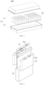
FIG. 4 is a schematic structural diagram of a cell according to an embodiment of the present application; -
FIG. 5 is a schematic structural diagram of the cell shown inFIG. 4 during winding; and -
FIG. 6 is a schematic structural diagram of a separator layer of the cell shown inFIG. 4 . - 1000. Vehicle; 100. Battery; 200. Controller; 300. Motor; 10. Case; 20. Cell; 11. First portion; 12. Second portion; 21. End cap; 22. Housing; 23. Cell assembly; 24. Separator layer; 25. Cathode electrode plate; 26. Anode electrode plate; 27. Winding device; 21a. Electrode terminal; 23a. Tab; 241. Heated region; 271. Heating portion; 272. Winding needle; 273. Winding roller.
- Embodiments of the technical solutions of the present application are described in detail below with reference to the accompanying drawings. The following embodiments are merely intended to more clearly illustrate the technical solutions of the present application, so they merely serve as examples, but are not intended to limit the scope of protection of the present application.
- Unless otherwise defined, all technical and scientific terms used herein have the same meanings as those commonly understood by those skilled in the art to which the present application belongs. The terms used herein are merely for the purpose of describing specific embodiments, but are not intended to limit the present application. The terms "include/comprise" and "has/have" and any variations thereof in the description and the claims of the present application as well as the brief description of the drawings described above are intended to cover non-exclusive inclusion.
- In the description of the embodiments of the present application, the technical terms "first", "second", etc. are merely used for distinguishing different objects, and are not to be construed as indicating or implying relative importance or implicitly indicating the number, particular order or primary-secondary relationship of the indicated technical features. In the description of the embodiments of the present application, the phrase "a plurality of" means two or more, unless otherwise explicitly and specifically defined.
- The phrase "embodiment" mentioned herein means that the specific features, structures, or characteristics described in conjunction with the embodiment can be encompassed in at least one embodiment of the present application. The phrase at various locations in the description does not necessarily refer to the same embodiment, or an independent or alternative embodiment exclusive of another embodiment. Those skilled in the art understand explicitly or implicitly that the embodiment described herein may be combined with another embodiment.
- In the description of the embodiments of the present application, the term "and/or" is merely intended to describe the associated relationship of associated objects, indicating that three relationships can exist. For example, A and/or B may include: only A exists, both A and B exist, and only B exists. In addition, the character "/" herein generally indicates an "or" relationship between the associated objects.
- In the description of the embodiments of the present application, the term "a plurality of" means two or more (including two), similarly the term "a plurality of groups" means two or more groups (including two groups), and the term "a plurality of pieces" means two or more pieces (including two pieces).
- In the description of the embodiments of the present application, the orientations or positional relationships indicated by the technical terms "central", "longitudinal", "transverse", "length", "width", "thickness", "upper", "lower", "front", "rear", "left", "right", "vertical", "horizontal", "top", "bottom", "inner", "outer", "clockwise", "counterclockwise", "axial", "radial", "circumferential", etc. are based on the orientations or positional relationships shown in the accompanying drawings, are merely intended to facilitate and simplify the description of the embodiments of the present application, rather than indicating or implying that the device or element referred to must have a particular orientation or be constructed and operated in a particular orientation, and therefore cannot be construed as limiting the embodiments of the present application.
- In the description of the embodiments of the present application, unless otherwise explicitly specified and defined, the technical terms such as "mount", "connected", "connect", and "fix" should be understood in a broad sense, for example, they may be a fixed connection, a detachable connection, or an integrated connection; may be a mechanical connection or an electrical connection; or may be a direct connection or an indirect connection by means of an intermediate medium, or may be internal communication between two elements or interaction between the two elements. For those of ordinary skill in the art, the specific meanings of the above terms in the embodiments of the present application can be understood according to specific situations.
- At present, from the perspective of the development of the market situation, lithium-ion batteries are widely used in electric vehicles and consumer electronics because of their advantages of high energy density, high output power, long cycle life, low environmental pollution, etc. With the continuous expansion of the application field of lithium-ion batteries, the market demand for the lithium-ion batteries is also expanding.
- A process of producing a lithium-ion battery generally includes the following steps. In a first step of preparing electrode slurries, mainly an electrode active material, a binder, a solvent, etc. are mixed together and are fully stirred and dispersed to form each slurry. In a second step of coating, the slurries prepared in the first step are each uniformly coated onto a current collector (an aluminum foil, a copper foil, etc.) with a specified thickness, and the solvent is dried. In a third step of punching electrode plates, the electrode plates manufactured in the previous step are punched into specified sizes and shapes. In a fourth step of stacking, a cathode electrode plate, an anode electrode plate, and a separator are assembled together, and a cell is formed after gluing is completed. In a fifth step of assembling a pouch battery, the cell produced in the previous step is mounted into a punched aluminum-plastic film, and top sealing, side sealing, etc. are completed (with an electrolyte injection port reserved) to form a pouch battery without electrolyte injection. In a sixth step of injecting an electrolyte, a specified amount of electrolyte is injected into the pouch cell. In a seventh step of sealing the battery, a gas inside the cell is pumped out in a vacuum environment to complete the sealing.
- Further, as lithium-ion batteries fall into wound batteries and flat batteries, a winding step is further provided in the above stacking step for the wound battery. The cathode electrode plate and the anode electrode plate are attached to the separator, and winding is then performed to form the wound battery. Next, assembly is performed.
- The wound battery is made by winding electrode plates with a thickness of only about 1 millimeter (mm) at a high pressure, and is made by special technological means. Therefore, compared with the flat plate battery, the wound battery has the following characteristics: 1. super high-rate discharge capacity; 2. excellent high- and low-temperature performance; 3. stable high output voltage; 4. higher energy density; 5. excellent anti-vibration performance; and 6. capability of being charged quickly and longer service life. As a result, wound batteries have been increasingly widely used in the market.
- With the widespread use of wound batteries, people's requirements for the performance of the wound batteries are also increasing. In order to facilitate use, people require the wound batteries to have a higher energy density and a smaller volume. Based on this, when the winding of the wound battery is completed, a pressure during pressing will be greater.
- However, the applicant has found that as the pressure during pressing continuously increases, a bending angle of a bent portion of the wound battery becomes smaller. As a result, the bending angle of the bent portion of each of the cathode electrode plate and the anode electrode plate becomes smaller, greatly increasing the probability of a coating falling off at the bent portions of the cathode electrode plate and the anode electrode plate, and thus increasing the risk of lithium precipitation of the battery.
- Further, the applicant has noticed that the separator layer is provided with a PCS polymer, which is specifically composed of PVDF, that is, polyvinylidene fluoride. This component melts at a certain temperature, and after melting, the separator layer will have a bonding effect. On this basis, the applicant has thought that if the PCS polymer of the separator layer is melted under a specific condition, the cathode electrode plate and the anode electrode plate can be bonded and fixed to each other by means of the polymer itself, which not only solves the bonding problem between the cathode electrode plate and the anode electrode plate, but also simplifies the structure of the wound battery without adding an external structure, thereby enabling the wound battery to have a smaller volume after being pressed.
- Based on the above considerations, in order to solve the problem of lithium precipitation caused by generation of a gap between bent portions of the cathode electrode plate and the anode electrode plate while reducing the volume of the wound battery, the applicant has designed a cell winding process through in-depth research, which reduces the volume of the wound battery and can solve the problem of lithium precipitation and short circuit of the wound battery by means of the structure of the separator layer itself and by special technological means.
- The cell disclosed in the embodiment of the present application may be used in, but not limited to, a power consuming device such as a vehicle, a ship or an aircraft. A power supply system of the power consuming device may be composed of the cell, the battery, etc. disclosed in the present application. This contributes to bonding and fixing the cathode electrode plate to the anode electrode plate, prevents lithium precipitation caused by the occurrence of a gap between the cathode electrode plate and the anode electrode plate, prevents lithium precipitation on an anode surface caused by a too long lithium ion transport path during charging and discharging, and further improves the safety performance of the battery.
- An embodiment of the present application provides a power consuming device using a battery as a power supply. The power consuming device may be, but is not limited to, a mobile phone, a tablet, a notebook computer, an electric toy, an electric tool, a battery cart, an electric vehicle, a ship, a spacecraft, etc. The electric toy may include a stationary or mobile electric toy, such as a game console, an electric vehicle toy, an electric ship toy and an electric airplane toy. The spacecraft may include an airplane, a rocket, a space shuttle, a spaceship, etc.
- In the following embodiments, for ease of illustration, an example in which a power consuming device according to an embodiment of the present application is a
vehicle 1000 is taken for description. - Referring to
FIG. 1, FIG. 1 is a schematic structural diagram of avehicle 1000 according to some embodiments of the present application. Thevehicle 1000 may be a fuel vehicle, a gas vehicle, or a new energy vehicle. The new energy vehicle may be a battery electric vehicle, a hybrid electric vehicle, an extended-range vehicle, etc. Abattery 100 is provided inside thevehicle 1000, and thebattery 100 may be arranged at a bottom, a head or a tail of thevehicle 1000. Thebattery 100 may be configured to supply power to thevehicle 1000. For example, thebattery 100 may be used as a power supply for operating thevehicle 1000. Thevehicle 1000 may further include acontroller 200 and amotor 300. Thecontroller 200 is configured to control thebattery 100 to supply power to themotor 300, for example, to meet working power requirements during starting, navigation and traveling of thevehicle 1000. - In some embodiments of the present application, the
battery 100 may not only serve as a power supply for operating thevehicle 1000, but also serve as a power supply for driving thevehicle 1000, in place of or partially in place of fuel or natural gas, to supply driving power to thevehicle 1000. - Referring to
FIG. 2, FIG. 2 is a schematic structural diagram of a battery according to an embodiment of the present application. Thebattery 100 includes acase 10 and acell 20. Thecell 20 is accommodated in thecase 10. Thecase 10 is configured to provide an accommodating space for thecell 20, and thecase 10 may be of various structures. In some embodiments, thecase 10 may include afirst portion 11 and asecond portion 12. Thefirst portion 11 and thesecond portion 12 are fitted to each other in a covering manner. Thefirst portion 11 and thesecond portion 12 jointly define an accommodating space for accommodating thecell 20. Thesecond portion 12 may be of a hollow structure with one end open, thefirst portion 11 may be of a plate-like structure, and thefirst portion 11 covers an open side of thesecond portion 12 such that thefirst portion 11 and thesecond portion 12 jointly define the accommodating space. Alternatively, thefirst portion 11 and thesecond portion 12 each may be of a hollow structure with one side open, and the open side of thefirst portion 11 covers the open side of thesecond portion 12. Of course, thecase 10 formed by thefirst portion 11 and thesecond portion 12 may be in various shapes such as a cylinder and a cuboid. - In the
battery 100, a plurality ofcells 20 may be provided. The plurality ofcells 20 may be connected in series or in parallel or in series-parallel. The series-parallel connection means that some of the plurality ofcells 20 are in series connection and some are in parallel connection. The plurality ofcells 20 may be directly connected to each other in series or in parallel or in series-parallel, and then a whole composed of the plurality ofcells 20 is accommodated in thecase 10. Of course, thebattery 100 may also be accommodated in thecase 10 as a whole that is formed by firstly connecting a plurality ofcells 20 in series or in parallel or in series-parallel to form a plurality of battery modules, and then connecting the plurality of battery modules in series or in parallel or in series-parallel. Thebattery 100 may further include other structures. For example, thebattery 100 may further include a bus component configured to implement electrical connections between the plurality ofcells 20. - Referring to
FIG. 3, FIG. 3 is a schematic structural diagram of a cell according to an embodiment of the present application. Eachcell 20 may be a secondary battery or a primary battery; or may be a lithium-sulfur battery, a sodium-ion battery, or a magnesium-ion battery, but is not limited thereto. Thecell 20 may be in a cylindrical shape, a flat shape, a cuboid shape, or another shape. Specifically, thecell 20 refers to a smallest unit of a battery. Thecell 20 includes anend cap 21, ahousing 22, acell assembly 23 and other functional components. - The
end cap 21 refers to a component that covers an opening of thehousing 22 to isolate an internal environment of thecell 20 from an external environment. Without limitation, theend cap 21 may be shaped to adapt to the shape of thehousing 22 so as to mate with thehousing 22. Optionally, theend cap 21 may be made of a material (for example, an aluminum alloy) with a certain hardness and strength. In this way, theend cap 21 is less prone to deformation when subjected to compression and collision, so that thecell 20 can have a higher structural strength and the safety performance can also be improved. Functional components, such aselectrode terminals 21a, may be arranged on theend cap 21. Theelectrode terminals 21a may be configured to be electrically connected to thecell assembly 23, so as to output or input electric energy for thecell 20. In some embodiments, a pressure relief mechanism, which is configured to release an internal pressure when the internal pressure or temperature of thecell 20 reaches a threshold, may be further provided on theend cap 21. Theend cap 21 may be made of various materials, such as copper, iron, aluminum, stainless steel, an aluminum alloy, and plastic, which is not specifically limited in the embodiments of the present application. In some embodiments, an insulating member may be further provided on an inner side of theend cap 21. The insulating member may be used to isolate electrical connection components in thehousing 22 from theend cap 21 in order to reduce the risk of short circuit. For example, the insulating member may be made of plastic, rubber, etc. - The
housing 22 is an assembly configured to cooperate with theend cap 21 to form the internal environment of thecell 20. The formed internal environment may be used to accommodate thecell assembly 23, an electrolyte, and other components. Thehousing 22 and theend cap 21 may be separate components, and thehousing 22 may be provided with an opening, at which theend cap 21 covers the opening to form the internal environment of thecell 20. Without limitation, theend cap 21 and thehousing 22 may also be integrated with each other. Specifically, theend cap 21 and thehousing 22 may form a common connection face before other components are inserted into the housing. When the interior of thehousing 22 needs to be packaged, theend cap 21 then covers thehousing 22. Thehousing 22 may have various shapes and various sizes, for example, in the shape of a cuboid, a cylinder, a hexagonal prism, etc. Specifically, thehousing 22 may be shaped depending on the specific shape and size of thecell assembly 23. Thehousing 22 may be made of various materials, such as copper, iron, aluminum, stainless steel, an aluminum alloy, and plastic, which is not specially limited in the embodiments of the present application. - The
cell assembly 23 is a component in thecell 20 where an electrochemical reaction takes place. Thehousing 22 may contain one ormore cell assemblies 23. Thecell assembly 23 is mainly formed by winding or stacking a cathode electrode plate and an anode electrode plate, and is typically provided with a separator between the cathode electrode plate and the anode electrode plate. Portions of the cathode electrode plate and the anode electrode plate that each have an active material form a main body portion of thecell assembly 23, and portions of the cathode electrode plate and the anode electrode plate that have no active material each form atab 23a. A cathode tab and an anode tab may be located at one end of the main body portion together or at two ends of the main body portion respectively. During charging/discharging of the battery, the cathode active material and the anode active material react with the electrolyte, and thetabs 23a are connected to theelectrode terminals 21a to form a current loop. - Referring to
FIGS. 4, 5 and 6 , an embodiment of the present application provides a cell winding process, including the following steps. - In a rolling-up step S10, starting ends of a
separator layer 24, acathode electrode plate 25, and ananode electrode plate 26 are fixed to a windingdevice 27 configured to wind a cell, and theseparator layer 24 is placed between thecathode electrode plate 25 and theanode electrode plate 26. - In a heating step S20, a heating portion 271 is arranged on the winding
device 27, and the heating portion 271 heatsheated regions 241 on two surfaces of theseparator layer 24 that are respectively attached to thecathode electrode plate 25 and theanode electrode plate 26. - Since the
separator layer 24 is located between thecathode electrode plate 25 and theanode electrode plate 26, theheated regions 241 on the two surfaces of theseparator layer 24 that respectively face thecathode electrode plate 25 and theanode electrode plate 26 are heated, so that a PCS polymer of the separator layer is melted and then wound, and thecathode electrode plate 25 and theanode electrode plate 26 can thus be closely bonded to theseparator layer 24. - It should be noted that the heating portion 271 may be provided as a heating sheet, which is attached to the
separator layer 24 by means of the windingdevice 27, so as to heat theseparator layer 24. It may be understood that the heating portion 271 may alternatively be provided as another heating structure, such as a heating tube and an infrared heater, which is not described in detail herein. - In some embodiments, in the heating step, the
heated region 241 is located on a side edge of theseparator layer 24 parallel to a winding direction, and the width of theheated region 241 ranges from 2 mm to 4 mm. - Specifically, the
heated region 241 is at an edge of theseparator layer 24 and extends inwardly from the edge by 2 mm to 4 mm. In addition, twoheated regions 241 are generally included, and are respectively located on two side edges of theseparator layer 24, and each have a width of 2 mm to 4 mm. That is, a left edge and a right edge of theseparator layer 24 are both heated, so that thecathode electrode plate 25 and theanode electrode plate 26 can be attached to theseparator layer 24 more closely. - In addition, it has been experimentally verified that, if the width of the
heated region 241 is less than 2 mm, a bonding width is too small, resulting in a poor effect of bonding thecathode electrode plate 25 and theanode electrode plate 26 to theseparator layer 24, making it impossible to fix thecathode electrode plate 25 and theanode electrode plate 26. If the width of theheated region 241 is greater than 4 mm, intercalation and deintercalation of lithium ions in a bonding region are affected, thus deteriorating the performance of the cell. - In some embodiments, in the heating step, the length of the
heated region 241 is at least three turns. That is, theheated region 241 on theseparator layer 24 should enable thecathode electrode plate 25, theseparator layer 24 and theanode electrode plate 26 to be jointly wound for at least three turns. If the length of theheated region 241 is less than three turns, thecathode electrode plate 25 and theanode electrode plate 26 cannot be effectively bonded to the separator layer, and a fixing effect cannot be achieved. - In addition, in the heating step, a heating temperature of the heating portion 271 ranges from 90°C to 130°C. Specifically, since the
separator layer 24 is of a fibrous structure, several small through-holes are distributed in the separator layer, and the through-holes provide channels for transfer of lithium ions. If the heating temperature is greater than 130°C, the melting of theseparator layer 24 is likely to lead to blockage of original micropores in the separator layer, affecting the transfer of lithium ions during charging and discharging, and thus deteriorating resistance, capacity, cycle and other properties of the battery. If the heating temperature is less than 90°C, the PCS polymer of theseparator layer 24 cannot be melted, and a bonding and fixing effect cannot be achieved. - In a winding step S30, a winding
needle 272 is arranged on the windingdevice 27, and theheated separator layer 24, thecathode electrode plate 25, and theanode electrode plate 26 are wound by means of the windingneedle 272. - In a pre-pressing step S40, a cell is obtained after the winding step is completed, the winding
needle 272 is pulled out from the cell, and a pressure is applied for pre-pressing to shape and bind the electrode plates of the cell. - Specifically, after the winding
needle 272 is pulled out from the cell upon the completion of the winding, the multiple layers of electrode plates will be retracted due to stress release. In order to avoid the above situation, a proper pressure is applied to the wound cell for pre-pressing, which can achieve a shaping and binding effect and improve the performance of the cell. - In some embodiments, the winding
device 27 in the aforementioned cell winding process includes a plurality of winding rollers 273 configured to convey the separator layer, and all the winding rollers 273 are arranged spaced apart from each other in a conveying direction of theseparator layer 24. Specifically, in this embodiment, theseparator layer 24, thecathode electrode plate 25, and theanode electrode plate 26 respectively correspond to the plurality of winding rollers 273. Since theseparator layer 24, thecathode electrode plate 25, and theanode electrode plate 26 each have a large length before winding, it is necessary to convey and transfer theseparator layer 24, thecathode electrode plate 25, and theanode electrode plate 26 by means of the plurality of winding rollers 273. - In some embodiments, the heating portion 271 is arranged on one winding roller 273 of the plurality of winding rollers 273 that is close to the winding
needle 272. That is, the heating portion 271 is arranged on the winding roller 273 closest to the windingneedle 272, so that the failure to fix theheated separator layer 24 due to cooling during conveying can be prevented. - Based on the same concept as the aforementioned cell winding process, the present application further provides a cell winding device configured to operate the aforementioned cell winding process, the cell winding device including a winding
device 27 configured to wind a cell. A heating portion 271 is arranged on the windingdevice 27, to heatheated regions 241 on two surfaces of theseparator layer 24 that are respectively attached to thecathode electrode plate 25 and theanode electrode plate 26. - Specifically, during winding of the cell, the
separator layer 24 is placed between thecathode electrode plate 25 and theanode electrode plate 26 to isolate thecathode electrode plate 25 from theanode electrode plate 26. Further, theheated regions 241 on the two surfaces of theseparator layer 24 that respectively face thecathode electrode plate 25 and theanode electrode plate 26 are heated, so that a PCS polymer of the separator layer is melted. Therefore, during the winding, the two side surfaces of theseparator layer 24 that face thecathode electrode plate 25 and theanode electrode plate 26 are both adhesive. In this way, thecathode electrode plate 25 and theanode electrode plate 26 can be closely bonded to theseparator layer 24 during the winding. - It should be noted that the heating portion 271 may be provided as a heating sheet, which is attached to the
separator layer 24 by means of the windingdevice 27, so as to heat theseparator layer 24. It may be understood that the heating portion 271 may alternatively be provided as another heating structure, such as a heating tube and an infrared heater, which is not described in detail herein. - In some embodiments, the heating portion 271 is located at an edge of the
separator layer 24 parallel to a winding direction, and has a heating width of 2 mm to 4 mm. - Specifically, the edge of the
separator layer 24 is heated by the heating portion 271, and the heating width is 2 mm to 4 mm. During the winding, edges of thecathode electrode plate 25 and theanode electrode plate 26 can be closely bonded to theseparator layer 24, so that a fixed connection can be achieved. Moreover, the heating portion 271 heats two side edges of theseparator layer 24 in the winding direction, and the heating widths on two sides each are 2 mm to 4 mm. In this way, it can be ensured that the two sides of theseparator layer 24 both have bonding capabilities. - In addition, it has been experimentally verified that, if the heating width is less than 2 mm, a bonding width is too small, resulting in a poor effect of bonding the
cathode electrode plate 25 and theanode electrode plate 26 to theseparator layer 24, making it impossible to fix thecathode electrode plate 25 and theanode electrode plate 26. If the heating width is greater than 4 mm, intercalation and deintercalation of lithium ions in a bonding region are affected, thus deteriorating the performance of the cell. - In some embodiments, the heating length of the heating portion 271 is at least three turns. That is, the heating length of the heating portion 271 on the
separator layer 24 should enable thecathode electrode plate 25, theseparator layer 24, and theanode electrode plate 26 to be jointly wound for at least three turns. If the heating length is less than three turns, thecathode electrode plate 25 and theanode electrode plate 26 cannot be effectively bonded to theseparator layer 24, and a fixing effect cannot be achieved. - In some embodiments, a heating temperature of the heating portion 271 ranges from 90°C to 130°C. Specifically, since the
separator layer 24 is of a fibrous structure, several small through-holes are distributed in the separator layer, and the through-holes provide channels for transfer of lithium ions. If the heating temperature is greater than 130°C, the melting of theseparator layer 24 is likely to lead to blockage of original micropores in the separator layer, affecting the transfer of lithium ions during charging and discharging, and thus deteriorating resistance, capacity, cycle and other properties of the battery. If the heating temperature is less than 90°C, the PCS polymer of theseparator layer 24 cannot be melted, and a bonding and fixing effect cannot be achieved. - In some embodiments, the winding
device 27 includes a plurality of winding rollers 273 configured to convey theseparator layer 24, and all the winding rollers 273 are arranged spaced apart from each other in a conveying direction of theseparator layer 24. - Specifically, the
separator layer 24, thecathode electrode plate 25, and theanode electrode plate 26 respectively correspond to the plurality of winding rollers 273. Since theseparator layer 24, thecathode electrode plate 25, and theanode electrode plate 26 each have a large length before winding, it is necessary to convey and transfer theseparator layer 24, thecathode electrode plate 25, and theanode electrode plate 26 by means of the plurality of winding rollers 273. - In some embodiments, the heating portion 271 is arranged on one winding roller 273 of the plurality of winding rollers 273 that is close to the winding
needle 272. That is, the heating portion 271 is arranged on the winding roller 273 closest to the windingneedle 272, so that the failure to fix theheated separator layer 24 due to cooling during conveying can be prevented. - Based on the same concept as the aforementioned cell winding device, the present application further provides a cell, which can be prepared by means of the cell winding process described above.
- Based on the same concept as the aforementioned cell, the present application further provides a battery, including a housing, and the cell described above. The cell is arranged in the housing.
- Based on the same concept as the battery described above, the present application further provides a power consuming device, including a power consuming body, and the battery described above.
- During specific use of the present application, a heating portion 271 is first arranged on one winding roller 273, which is closest to a winding
needle 272, of the plurality of winding rollers 273 corresponding to theseparator layer 24. The heating portion heats two sides of the edge of theseparator layer 24, and the heating width range is set to 2 mm to 4 mm. - Next, the
separator layer 24, acathode electrode plate 25, and ananode electrode plate 26 are respectively fixed to corresponding winding rollers 273, and theseparator layer 24, thecathode electrode plate 25, and theanode electrode plate 26 are respectively transferred to the windingneedle 272 by means of guidance of the winding rollers 273. In this process, it is necessary to keep theseparator layer 24 between thecathode electrode plate 25 and theanode electrode plate 26. - After the
separator layer 24, thecathode electrode plate 25, and theanode electrode plate 26 are fixed, a rolling-up step can be started. In addition, the heating temperature of the heating portion 271 is controlled at 90°C-130°C, and theseparator layer 24 is heated synchronously during winding. Theheated separator layer 24 is bonded to thecathode electrode plate 25 and theanode electrode plate 26 respectively during the winding, so as to achieve a fixing effect. - After the winding of the cell is completed, the winding
needle 272 is pulled out from the cell, and a certain pressure is applied to pre-press the cell. In this way, an effect of shaping and binding the electrode plates of the cell can be achieved, and a gap between the electrode plates can be prevented from becoming larger during production. - The cell winding process, the cell winding device, the cell, the battery, and the power consuming device in the above embodiments have at least the following advantages.
- 1. The
separator layer 24 is heated, such that the PCS polymer of the separator layer is melted to have a bonding function, to fix thecathode electrode plate 25 and theanode electrode plate 26, and the electrode plates are bonded and fixed by means of the structure of theseparator layer 24 itself, thus achieving a simple operation process and high working efficiency. - 2. Since the structure of the
separator layer 24 itself is used to implement bonding, it is not necessary to add other bonding structures, the structure of the cell can be simplified to the greatest extent, and the thickness of the cell after winding can be reduced, thereby reducing the volume of the cell and improving the performance of the cell. - 3. The wound cell is pre-pressed, so that retraction between the multiple layers of electrode plates due to stress release can be avoided after the winding
needle 272 is pulled out from the cell, thus achieving an effect of shaping and binding the electrode plates of the cell and improving the performance of the cell. - Finally, it should be noted that the above embodiments are merely used for illustrating rather than limiting the technical solutions of the present application. Although the present application has been illustrated in detail with reference to the foregoing embodiments, it should be understood by those of ordinary skill in the art that the technical solutions described in the foregoing embodiments may still be modified, or some or all of the technical features thereof may be equivalently substituted; and such modifications or substitutions do not make the essence of the corresponding technical solution depart from the scope of the technical solutions of the embodiments of the present application, and should fall within the scope of the claims and the description of the present application. In particular, the technical features mentioned in the embodiments can be combined in any manner, provided that there is no structural conflict. The present application is not limited to the specific embodiments disclosed herein but includes all the technical solutions that fall within the scope of the claims.
Claims (16)
- A cell winding process, comprising:a rolling-up step in which starting ends of a separator layer, a cathode electrode plate, and an anode electrode plate are fixed to a winding device configured to wind a cell, and the separator layer is placed between the cathode electrode plate and the anode electrode plate;a heating step in which a heating portion is arranged on the winding device, and the heating portion heats heated regions on two surfaces of the separator layer that are respectively attached to the cathode electrode plate and the anode electrode plate; anda winding step in which a winding needle is arranged on the winding device, and the heated separator layer, the cathode electrode plate, and the anode electrode plate are wound by means of the winding needle.
- The cell winding process according to claim 1, wherein in the heating step, each heated region is located on a side edge of the separator layer parallel to a winding direction, and the width of the heated region ranges from 2 mm to 4 mm.
- The cell winding process according to claim 1 or 2, wherein in the heating step, each heated region is located on a side edge of the separator layer parallel to a winding direction, and the length of the heated region is at least three turns.
- The cell winding process according to any one of claims 1 to 3, wherein in the heating step, a heating temperature of the heating portion ranges from 90°C to 130°C.
- The cell winding process according to any one of claims 1 to 4, after the winding step, further comprising:
a pre-pressing step in which a cell is obtained after the winding step is completed, the winding needle is pulled out from the cell, and a pressure is applied for pre-pressing to shape and bind the electrode plates of the cell. - The cell winding process according to any one of claims 1 to 5, wherein the winding device comprises a plurality of winding rollers configured to convey the separator layer, and all the winding rollers are arranged spaced apart from each other in a conveying direction of the separator layer.
- The cell winding process according to claim 6, wherein in the heating step, the heating portion is arranged on one of the plurality of winding rollers that is close to the winding needle.
- A cell winding device configured to operate a cell winding process according to any one of claims 1 to 7, the cell winding device comprising a winding device configured to wind a cell, wherein a heating portion is arranged on the winding device, to heat heated regions on two surfaces of a separator layer that are respectively attached to a cathode electrode plate and an anode electrode plate.
- The cell winding device according to claim 8, wherein the heating portion is located at an edge of the separator layer parallel to a winding direction, and has a heating width ranging from 2 mm to 4 mm.
- The cell winding device according to claim 8 or 9, wherein the heating portion is located at an edge of the separator layer parallel to a winding direction, and has a heating length of at least three turns.
- The cell winding device according to any one of claims 8 to 10, wherein a heating temperature of the heating portion ranges from 90°C to 130°C.
- The cell winding device according to any one of claims 8 to 11, wherein the winding device comprises a plurality of winding rollers configured to transport the separator layer, and all the winding rollers are arranged spaced apart from each other in a conveying direction of the separator layer.
- The cell winding device according to claim 12, wherein the heating portion is arranged on one of the plurality of winding rollers that is close to a winding needle.
- A cell prepared by means of a cell winding process according to any one of claims 1 to 7.
- A battery, comprising a housing, and a cell according to claim 14, wherein the cell is arranged in the housing.
- A power consuming device, comprising a power consuming body and a battery according to claim 15.
Applications Claiming Priority (2)
| Application Number | Priority Date | Filing Date | Title |
|---|---|---|---|
| CN202111335028.7A CN115842168B (en) | 2021-11-11 | 2021-11-11 | Battery cell winding process, battery cell winding device, battery cell, battery and electricity utilization device |
| PCT/CN2022/128835 WO2023083045A1 (en) | 2021-11-11 | 2022-11-01 | Cell winding process, cell winding apparatus, cell, battery, and electric apparatus |
Publications (2)
| Publication Number | Publication Date |
|---|---|
| EP4421941A1 true EP4421941A1 (en) | 2024-08-28 |
| EP4421941A4 EP4421941A4 (en) | 2025-06-11 |
Family
ID=85574572
Family Applications (1)
| Application Number | Title | Priority Date | Filing Date |
|---|---|---|---|
| EP22891841.3A Pending EP4421941A4 (en) | 2021-11-11 | 2022-11-01 | CELL WINDING METHOD, CELL WINDING APPARATUS, CELL, BATTERY AND ELECTRICAL APPARATUS |
Country Status (4)
| Country | Link |
|---|---|
| US (1) | US20260081201A1 (en) |
| EP (1) | EP4421941A4 (en) |
| CN (1) | CN115842168B (en) |
| WO (1) | WO2023083045A1 (en) |
Families Citing this family (3)
| Publication number | Priority date | Publication date | Assignee | Title |
|---|---|---|---|---|
| CN220272567U (en) * | 2023-06-30 | 2023-12-29 | 厦门海辰储能科技股份有限公司 | Cell structure, battery and energy storage device |
| CN220617765U (en) * | 2023-07-03 | 2024-03-19 | 宁德时代新能源科技股份有限公司 | Winding equipment and battery production line |
| CN120184521B (en) * | 2025-05-21 | 2026-04-10 | 江苏时代新能源科技有限公司 | Battery monomer, battery device and electric equipment |
Family Cites Families (10)
| Publication number | Priority date | Publication date | Assignee | Title |
|---|---|---|---|---|
| CN102290607B (en) * | 2011-06-27 | 2013-11-20 | 深圳市吉阳自动化科技有限公司 | Electrode plate-winding method and electrode plate winder |
| CN104241598B (en) * | 2013-06-18 | 2016-12-28 | 赵军辉 | Composite negative pole, preparation method and lithium-sulfur rechargeable battery for lithium-sulfur rechargeable battery |
| KR102164576B1 (en) * | 2016-02-12 | 2020-10-12 | 주식회사 엘지화학 | Method Preparing Electrode Assembly And Electrode Assembly Prepared Using the Same |
| KR102265219B1 (en) * | 2017-02-08 | 2021-06-16 | (주)엘지에너지솔루션 | Manufacturing Method of Battery Cell Comprising Step of Binding Membrane Surplus |
| CN208873839U (en) * | 2018-09-12 | 2019-05-17 | 合肥国轩高科动力能源有限公司 | A lithium-ion battery cutting and stacking device |
| CN110380135A (en) * | 2019-07-04 | 2019-10-25 | 湖北锂诺新能源科技有限公司 | A kind of combination process preparation winding battery core pole piece and its lithium ion battery method |
| CN110911762A (en) * | 2019-10-30 | 2020-03-24 | 郑州比克电池有限公司 | A kind of method for preventing lithium battery cell from winding and wrinkling |
| CN111653833B (en) * | 2020-04-30 | 2022-05-17 | 广州超音速自动化科技股份有限公司 | Process for winding thermosol on lithium battery |
| CN112421129B (en) * | 2021-01-25 | 2021-05-18 | 江苏时代新能源科技有限公司 | Battery cell manufacturing equipment and method thereof |
| CN112510245B (en) * | 2021-01-29 | 2021-05-18 | 江苏时代新能源科技有限公司 | Battery cell manufacturing device and method |
-
2021
- 2021-11-11 CN CN202111335028.7A patent/CN115842168B/en active Active
-
2022
- 2022-11-01 WO PCT/CN2022/128835 patent/WO2023083045A1/en not_active Ceased
- 2022-11-01 EP EP22891841.3A patent/EP4421941A4/en active Pending
-
2024
- 2024-05-10 US US18/661,562 patent/US20260081201A1/en active Pending
Also Published As
| Publication number | Publication date |
|---|---|
| US20260081201A1 (en) | 2026-03-19 |
| CN115842168A (en) | 2023-03-24 |
| CN115842168B (en) | 2026-03-03 |
| WO2023083045A1 (en) | 2023-05-19 |
| EP4421941A4 (en) | 2025-06-11 |
Similar Documents
| Publication | Publication Date | Title |
|---|---|---|
| US20260081201A1 (en) | Cell winding process, cell winding device, cell, battery, and power consuming device | |
| EP2017918B1 (en) | Assembly battery, and vehicle with assembly battery | |
| CN217589312U (en) | Separators, battery cells, hot pressing molds, batteries and electrical devices | |
| CN219303812U (en) | Battery cells, batteries and electrical devices | |
| CN216354646U (en) | Power battery | |
| EP4672463A1 (en) | BATTERY, ELECTRICAL DEVICE AND ENERGY STORAGE DEVICE | |
| CN216354436U (en) | Heat exchange mechanism of battery, battery and electric device | |
| CN220456475U (en) | Battery monomer, battery and power consumption device | |
| US20230411700A1 (en) | Electrode assembly, manufacturing method therefor, battery cell, battery, and electric apparatus | |
| WO2025148153A1 (en) | Battery cell, battery, and electric device | |
| CN217768705U (en) | Pole piece structure, electric core subassembly, battery monomer, battery and power consumption device | |
| CN217588987U (en) | Current collectors, pole pieces, battery cells, hot pressing molds, batteries and electrical devices | |
| WO2023131054A1 (en) | Battery electrode plate, coating method, coating apparatus, and battery cell | |
| WO2023088052A1 (en) | Electrode assembly, winding method, device, battery cell, battery, and electrical apparatus | |
| US20250105365A1 (en) | Electrode assembly and preparation method therefor, secondary battery, and power consuming device | |
| CN116745953A (en) | Electrode sheet, electrode assembly, battery cell, battery, electrical device and manufacturing method | |
| CN116648808A (en) | Electrode assembly, manufacturing method thereof, battery cell, battery and power utilization device | |
| US20230387507A1 (en) | Battery and electrical apparatus | |
| CN116745954A (en) | Battery cells, batteries, electrical devices and methods of manufacturing battery cells | |
| CN220420607U (en) | Battery monomer, battery and power consumption device | |
| CN222763045U (en) | Battery device and electricity utilization device | |
| CN222775360U (en) | Battery cell, battery device and electricity utilization device | |
| CN223414248U (en) | Battery monomer, related device, system and charging network | |
| US20260045666A1 (en) | Battery cell, battery, and electric apparatus | |
| CN223712919U (en) | Battery device and electric equipment |
Legal Events
| Date | Code | Title | Description |
|---|---|---|---|
| STAA | Information on the status of an ep patent application or granted ep patent |
Free format text: STATUS: THE INTERNATIONAL PUBLICATION HAS BEEN MADE |
|
| PUAI | Public reference made under article 153(3) epc to a published international application that has entered the european phase |
Free format text: ORIGINAL CODE: 0009012 |
|
| STAA | Information on the status of an ep patent application or granted ep patent |
Free format text: STATUS: REQUEST FOR EXAMINATION WAS MADE |
|
| 17P | Request for examination filed |
Effective date: 20240524 |
|
| AK | Designated contracting states |
Kind code of ref document: A1 Designated state(s): AL AT BE BG CH CY CZ DE DK EE ES FI FR GB GR HR HU IE IS IT LI LT LU LV MC ME MK MT NL NO PL PT RO RS SE SI SK SM TR |
|
| RAP1 | Party data changed (applicant data changed or rights of an application transferred) |
Owner name: CONTEMPORARY AMPEREX TECHNOLOGY(HONG KONG) LIMITED |
|
| DAV | Request for validation of the european patent (deleted) | ||
| DAX | Request for extension of the european patent (deleted) | ||
| REG | Reference to a national code |
Ref country code: DE Ref legal event code: R079 Free format text: PREVIOUS MAIN CLASS: H01M0010058700 Ipc: H01M0010040000 |
|
| A4 | Supplementary search report drawn up and despatched |
Effective date: 20250512 |
|
| RIC1 | Information provided on ipc code assigned before grant |
Ipc: H01M 10/04 20060101AFI20250506BHEP |