EP4421841A2 - Structural body, x-ray generation apparatus, x-ray computed tomography (ct) apparatus, and manufacturing method for manufacturing heat dissipation portion - Google Patents
Structural body, x-ray generation apparatus, x-ray computed tomography (ct) apparatus, and manufacturing method for manufacturing heat dissipation portion Download PDFInfo
- Publication number
- EP4421841A2 EP4421841A2 EP24158379.8A EP24158379A EP4421841A2 EP 4421841 A2 EP4421841 A2 EP 4421841A2 EP 24158379 A EP24158379 A EP 24158379A EP 4421841 A2 EP4421841 A2 EP 4421841A2
- Authority
- EP
- European Patent Office
- Prior art keywords
- concavo
- distance
- heat dissipation
- structural body
- convex
- Prior art date
- Legal status (The legal status is an assumption and is not a legal conclusion. Google has not performed a legal analysis and makes no representation as to the accuracy of the status listed.)
- Pending
Links
Images



Classifications
-
- A—HUMAN NECESSITIES
- A61—MEDICAL OR VETERINARY SCIENCE; HYGIENE
- A61B—DIAGNOSIS; SURGERY; IDENTIFICATION
- A61B6/00—Apparatus or devices for radiation diagnosis; Apparatus or devices for radiation diagnosis combined with radiation therapy equipment
- A61B6/40—Arrangements for generating radiation specially adapted for radiation diagnosis
-
- H—ELECTRICITY
- H01—ELECTRIC ELEMENTS
- H01J—ELECTRIC DISCHARGE TUBES OR DISCHARGE LAMPS
- H01J35/00—X-ray tubes
- H01J35/02—Details
- H01J35/04—Electrodes ; Mutual position thereof; Constructional adaptations therefor
- H01J35/08—Anodes; Anti cathodes
- H01J35/10—Rotary anodes; Arrangements for rotating anodes; Cooling rotary anodes
- H01J35/105—Cooling of rotating anodes, e.g. heat emitting layers or structures
-
- A—HUMAN NECESSITIES
- A61—MEDICAL OR VETERINARY SCIENCE; HYGIENE
- A61B—DIAGNOSIS; SURGERY; IDENTIFICATION
- A61B6/00—Apparatus or devices for radiation diagnosis; Apparatus or devices for radiation diagnosis combined with radiation therapy equipment
- A61B6/02—Arrangements for diagnosis sequentially in different planes; Stereoscopic radiation diagnosis
- A61B6/03—Computed tomography [CT]
- A61B6/032—Transmission computed tomography [CT]
- A61B6/035—Mechanical aspects of CT
-
- A—HUMAN NECESSITIES
- A61—MEDICAL OR VETERINARY SCIENCE; HYGIENE
- A61B—DIAGNOSIS; SURGERY; IDENTIFICATION
- A61B6/00—Apparatus or devices for radiation diagnosis; Apparatus or devices for radiation diagnosis combined with radiation therapy equipment
- A61B6/42—Arrangements for detecting radiation specially adapted for radiation diagnosis
-
- A—HUMAN NECESSITIES
- A61—MEDICAL OR VETERINARY SCIENCE; HYGIENE
- A61B—DIAGNOSIS; SURGERY; IDENTIFICATION
- A61B6/00—Apparatus or devices for radiation diagnosis; Apparatus or devices for radiation diagnosis combined with radiation therapy equipment
- A61B6/44—Constructional features of apparatus for radiation diagnosis
- A61B6/4488—Means for cooling
-
- G—PHYSICS
- G01—MEASURING; TESTING
- G01N—INVESTIGATING OR ANALYSING MATERIALS BY DETERMINING THEIR CHEMICAL OR PHYSICAL PROPERTIES
- G01N23/00—Investigating or analysing materials by the use of wave or particle radiation, e.g. X-rays or neutrons, not covered by groups G01N3/00 – G01N17/00, G01N21/00 or G01N22/00
- G01N23/02—Investigating or analysing materials by the use of wave or particle radiation, e.g. X-rays or neutrons, not covered by groups G01N3/00 – G01N17/00, G01N21/00 or G01N22/00 by transmitting the radiation through the material
- G01N23/04—Investigating or analysing materials by the use of wave or particle radiation, e.g. X-rays or neutrons, not covered by groups G01N3/00 – G01N17/00, G01N21/00 or G01N22/00 by transmitting the radiation through the material and forming images of the material
- G01N23/046—Investigating or analysing materials by the use of wave or particle radiation, e.g. X-rays or neutrons, not covered by groups G01N3/00 – G01N17/00, G01N21/00 or G01N22/00 by transmitting the radiation through the material and forming images of the material using tomography, e.g. computed tomography [CT]
-
- G—PHYSICS
- G01—MEASURING; TESTING
- G01T—MEASUREMENT OF NUCLEAR OR X-RADIATION
- G01T1/00—Measuring X-radiation, gamma radiation, corpuscular radiation, or cosmic radiation
- G01T1/29—Measurement performed on radiation beams, e.g. position or section of the beam; Measurement of spatial distribution of radiation
- G01T1/2914—Measurement of spatial distribution of radiation
- G01T1/2985—In depth localisation, e.g. using positron emitters; Tomographic imaging (longitudinal and transverse section imaging; apparatus for radiation diagnosis sequentially in different planes, steroscopic radiation diagnosis)
-
- H—ELECTRICITY
- H05—ELECTRIC TECHNIQUES NOT OTHERWISE PROVIDED FOR
- H05G—X-RAY TECHNIQUE
- H05G1/00—X-ray apparatus involving X-ray tubes; Circuits therefor
- H05G1/02—Constructional details
- H05G1/025—Means for cooling the X-ray tube or the generator
-
- H—ELECTRICITY
- H01—ELECTRIC ELEMENTS
- H01J—ELECTRIC DISCHARGE TUBES OR DISCHARGE LAMPS
- H01J2235/00—X-ray tubes
- H01J2235/08—Targets (anodes) and X-ray converters
- H01J2235/081—Target material
-
- H—ELECTRICITY
- H01—ELECTRIC ELEMENTS
- H01J—ELECTRIC DISCHARGE TUBES OR DISCHARGE LAMPS
- H01J2235/00—X-ray tubes
- H01J2235/08—Targets (anodes) and X-ray converters
- H01J2235/085—Target treatment, e.g. ageing, heating
-
- H—ELECTRICITY
- H01—ELECTRIC ELEMENTS
- H01J—ELECTRIC DISCHARGE TUBES OR DISCHARGE LAMPS
- H01J2235/00—X-ray tubes
- H01J2235/08—Targets (anodes) and X-ray converters
- H01J2235/086—Target geometry
-
- H—ELECTRICITY
- H01—ELECTRIC ELEMENTS
- H01J—ELECTRIC DISCHARGE TUBES OR DISCHARGE LAMPS
- H01J2235/00—X-ray tubes
- H01J2235/12—Cooling
- H01J2235/1225—Cooling characterised by method
- H01J2235/1245—Increasing emissive surface area
- H01J2235/1254—Increasing emissive surface area with microscopic surface features
Definitions
- the present invention relates to a structural body, an X-ray generation apparatus, an X-ray computed tomography (CT) apparatus, and a manufacturing method for manufacturing a heat dissipation portion.
- CT computed tomography
- a technique for increasing the heat dissipation property may be applied to decrease an amount of the heat accumulated in the component.
- a technique for increasing the light absorption rate and improving the heat dissipation property by composing the surface of the component of a black material or applying or thermal-spraying the black material to the surface of the component.
- the present invention is directed to providing a structural body in which the heat dissipation property is improved.
- a structural body as specified in claims 1 to 11.
- an X-ray generation apparatus as specified in claim 12.
- an X-ray computed tomography (CT) apparatus as specified in claim 13.
- CT computed tomography
- a manufacturing method as specified in claims 14 to 15.
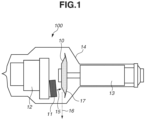
- FIG. 1 is a schematic view of an X-ray generation apparatus (a rotating anode X-ray tube).
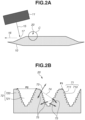
- Fig. 2A is an enlarged view illustrating an electron tube target and an electron emission source in the X-ray generation apparatus in Fig. 1 .
- Fig. 2B is an enlarged view of a portion surrounded by a circle C in Fig. 2A .
- an X-ray generation apparatus 100 includes an electron emission source 11 provided in a cathode assembly 12 and an electron tube target (hereinafter occasionally referred to simply as "target") 10 attached to an anode shaft 13.
- the electron emission source 11 forms a cathode
- the target 10 forms an anode.
- These members are stored in a container 14 in a vacuum state.
- the target 10 is rotated together with the anode shaft 13 by, for example, a coil (not illustrated) provided outside the container 14.
- An electron beam 15 emitted from the electron emission source 11 is focused by a focusing electrode (not illustrated), and the target 10 is irradiated with the electron beam 15.
- An X-ray 16 is generated from the target 10 irradiated with the electron beam 15, and the generated X-ray 16 is emitted from the container 14 to outside.
- a structural body that efficiently emits heat is formed by providing a heat dissipation portion having concavo-convex structures in the target 10.
- a high-melting-point metal that not only facilitates the emission of the X-ray 16 but also has a high heat resistance is desirable. Moreover, to stabilize the X-ray 16 to be emitted, a high-melting-point metal having a large heat capacity is desirable so that changes in the temperature of the target 10 can be prevented while the target 10 is being irradiated with the electron beam 15. Thus, it is desirable to use tungsten, molybdenum, niobium, tantalum, rhenium, hafnium, zirconium, or yttrium as the material of the target 10.
- the inside of the container 14 should be in a vacuum state.
- the degree of vacuum can be appropriately used from a low vacuum (a pressure of 1.0E-5 Pa) to an absolute vacuum (a pressure of 0 Pa) according to the purpose.
- a low vacuum a pressure of 1.0E-5 Pa
- an absolute vacuum a pressure of 0 Pa
- the pressure should be 1.0E-4 Pa to 1.0E-6 Pa.
- Fig. 2A illustrates an enlarged view of a main portion of the X-ray generation apparatus illustrated in Fig. 1 .
- the target 10 is irradiated with the electron beam 15 from the electron emission source 11.
- the X-ray 16 is emitted from the target 10 irradiated with the electron beam 15.
- heat is generated in an irradiated area 17 of the target 10 irradiated with the electron beam 15, and the target 10 enters a high-temperature state at 1000°C or more.
- a heat dissipation portion 20 having concavo-convex structures illustrated in Fig.
- the heat dissipation portion 20 may be provided in the entirety or a part of the external surface of the target 10.
- the irradiated area 17 of the target 10 irradiated with the electron beam 15 corresponds to "a component that can be a heat source”. Since the electron beam 15 generates heat, the irradiated area 17 and the electron emission source 11 that emits the electron beam 15 to the irradiated area 17 can also be collectively regarded as "a component that can be a heat source”.
- Fig. 2B is an enlarged view of a portion surrounded by a circle C in Fig. 2A .
- the surface of the heat dissipation portion 20 according to the present exemplary embodiment has a first concavo-convex structure 71 where a plurality of first convex portions 710 and a plurality of first concave portions 711 are alternately arranged.
- the first concavo-convex structure 71 is formed so that the distance between first convex portions 710 close to each other among the plurality of first convex portions 710 and/or the distance between first concave portions 711 close to each other among the plurality of first concave portions 711 is a constant pitch P1.
- the distance between the first convex portions 710 close to each other is the distance from the top of a certain convex portion 710 to the top of a convex portion 710 close to the certain convex portion 710.
- the distance between the first concave portions 711 close to each other is the distance from the bottom of a certain concave portion 711 to the bottom of a concave portion 711 close to the certain concave portion 711.
- a second concavo-convex structure 72 where a plurality of second convex portions 720 and a plurality of second concave portions 721 are alternately arranged is also formed.
- the second concavo-convex structure 72 is formed so that the distance between second convex portions 720 close to each other among the plurality of second convex portions 720 and/or the distance between second concave portions 721 close to each other among the plurality of second concave portions 721 is a constant pitch P2.
- the pitch P2 is longer than the pitch P1, and the first concavo-convex structure 71 is formed on the surface of the second concavo-convex structure 72.
- the pitches P1 and P2 are constant.
- the distance between the first convex portions 710 close to each other and/or the distance between the first concave portions 711 close to each other (hereinafter referred to as a "distance L1") does not necessarily need to be constant.
- the distance between the second convex portions 720 close to each other and/or the distance between the second concave portions 721 close to each other (hereinafter referred to as a "distance L2”) does not necessarily need to be constant.
- the first concavo-convex structure 71 and the second concavo-convex structure 72 are formed so that the shortest distance among the distances L2 is longer than the longest distance among the distances L1.
- the first concavo-convex structure 71 is formed so that the distance L1 between the first convex portions 710 close to each other and/or the distance L1 between the first concave portions 711 close to each other in the first concavo-convex structure 71 is less than half (1/2) of the peak wavelength of the electromagnetic wave of the heat emitted from the heat dissipation portion 20. This configuration improves the heat dissipation property of the heat dissipation portion 20.
- the distance L1 is greater than or equal to half (1/2) of the peak wavelength of the electromagnetic wave of the heat emitted from the heat dissipation portion 20, the heat dissipation property of the heat dissipation portion 20 decreases.
- the reason is considered as follows. As will be described below, to efficiently emit an electromagnetic wave at a wavelength ⁇ generated by heat emission, a structure capable of, if an electromagnetic wave having the same wavelength ⁇ as this electromagnetic wave is incident on the structure, absorbing the electromagnetic wave without reflecting the electromagnetic wave may be considered.
- the electromagnetic waves does not interfere with each other in the diffraction grating under the condition that the pitch P1 between the first convex portions 710 and/or the first concave portions 711 is less than or equal to half of the wavelength ⁇ .
- This is a so-called subwavelength structure (hereinafter referred to as "SWS”) and is a structure that does not reflect the electromagnetic wave at the wavelength ⁇ .
- the peak wavelength of the electromagnetic wave changes due to the temperature of a heating element that emits heat, i.e., the temperature of the target 10 (particularly, the heat dissipation portion 20) in the present exemplary embodiment, and is 3.00 ⁇ m at 700°C, 2.47 ⁇ m at 900°C, 1.84 ⁇ m at 1300°C, 1.63 ⁇ m at 1500°C, and 1.55 ⁇ m at 1600°C, for example.
- the distance L1 may be less than 1/2 of 3.00 ⁇ m. That is, it is desirable to form the first concavo-convex structure 71 so that the distance L1 is 50 nm or more and less than 1500 nm.
- the distance L1 is set based on the peak wavelength at 1300°C, which is the higher temperature. It is more desirable that the distance L1 should be less than 1/4 of the peak wavelength of the electromagnetic wave of the emitted heat. For example, it is desirable that the distance L1 should be 200 nm or more and 600 nm or less.
- the distance L2 between the second convex portions 720 close to each other and/or the distance L2 between the second concave portions 721 close to each other in the second concavo-convex structure 72 may be greater than the distance L1 in the first concavo-convex structure 71.
- the distance L2 should be 1 ⁇ m or more and 100 ⁇ m or less. It is more desirable that the distance L2 should be 10 ⁇ m or more and 50 ⁇ m or less. This can improve the heat dissipation property of the heat dissipation portion 20.
- the depth of concave portions 721 and/or the heigh of convex portions 720 may be 1 ⁇ m or more and 150 ⁇ m or less, and may be 10 ⁇ m or more and 100 ⁇ m or less.
- the heat dissipation property of the heat dissipation portion 20 is correlated with the absorption property of the heat dissipation portion 20. It can be said that a heat dissipation portion having a high absorption property also has a high heat dissipation property.
- FIG. 2B illustrates an electromagnetic wave 73 incident on the heat dissipation portion 20, an electromagnetic wave 74 reflected by the heat dissipation portion 20, and an electromagnetic wave 75 penetrating in (and that may be absorbed in) the heat dissipation portion 20.
- the pitch P1 between the first convex portions 710 and/or the first concave portions 711 in the first concavo-convex structure 71 is less than 1/2 of the peak wavelength of the emitted electromagnetic wave, the reflection of the electromagnetic wave 73 incident on the heat dissipation portion 20 is reduced due to the effect of the SWS, and it is possible to significantly improve the absorption rate of the electromagnetic wave 73.
- the electromagnetic wave 73 incident on the heat dissipation portion 20 is reflected into the second concave portions 721.
- the reflection of the reflected electromagnetic wave 74 is prevented due to the effect of the SWS by the first concavo-convex structure 71 formed on the surface of the second concavo-convex structure 72, but a part of the reflected electromagnetic wave 74 is further reflected into the second concave portions 721.
- Such a heat dissipation property improvement mechanism also applies to a case where the distance L1 between the first convex portions 710 close to each other and/or the distance L1 between the first concave portions 711 close to each other is not constant as in the pitch P1. Also in a case where the distance L2 between the second convex portions 720 close to each other and/or the distance L2 between the second concave portions 721 close to each other is not constant as in the pitch P2, it is possible to similarly improve the heat dissipation property.
- the first concavo-convex structure 71 is formed on the surface of the second concavo-convex structure 72.
- the second concavo-convex structure 72 does not necessarily need to be provided, and it is possible to improve the heat dissipation property due to the effect of the SWS so long as the first concavo-convex structure 71 is formed.
- the shapes of the first convex portions 710 and/or the first concave portions 711 forming the first concavo-convex structure 71 are not particularly limited. It is, however, desirable that the first convex portions 710 should be formed of particles attached to the surface of the heat dissipation portion 20.
- the first convex portions 710 have shapes in which particles are deposited, whereby the surface area of the first convex portions 710 is greater than that of another shape, and it is possible to improve the absorption rate of the electromagnetic wave.
- the first concavo-convex structure 71 is formed so that the particle size of the particles forming the first concavo-convex structure 71 is smaller than 1/2 of the peak wavelength of the emitted electromagnetic wave.
- the depth of the first concavo-convex structure 71 can be regarded as equivalent to the particle size of the particles.
- the first concavo-convex structure 71 should be formed of a metal having a high X-ray emission efficiency, a high melting point, and a large heat capacity.
- the metal having a high melting point is a metal having a melting point of 1500°C or more.
- tungsten is desirable, and molybdenum, niobium, tantalum, rhenium, hafnium, zirconium, or yttrium, which has a large heat capacity, is also suitable.
- the amount of nitrogen contained in a portion from the surface to a depth of 100 nm or less in the first concavo-convex structure 71 should be 1 at% (where "at%" signifies atomic percentage) or more, or the amount of oxygen contained in the portion should be 10 at% or less.
- 1 at% or more of nitrogen is incorporated into the surface and contributes to an improvement in the emissivity.
- the amount of contained oxygen should be 10 at% or less.
- the amount of contained nitrogen and the amount of contained oxygen do not necessarily need to be in the above ranges, and may be in appropriate ranges according to the purpose.
- FIG. 3 is a schematic diagram illustrating a laser processing machine 110 for manufacturing the heat dissipation portion 20.
- the surface of a member such as the target 10 according to the present exemplary embodiment is processed to partially remove a metal of the member with laser light using the laser processing machine 110 (i.e. laser ablation), thereby processing the heat dissipation portion 20 into a shape like the second concavo-convex structure 72 (hereinafter, the target 10 will occasionally be referred to as a "processing target member" in the sense that the target 10 is a member in which the heat dissipation portion 20 is formed).
- a metal removed from the processing target member becomes metal particles, and the metal particles deposit on the surface of the second concavo-convex structure 72, thereby forming the first concavo-convex structure 71 (see Fig. 2B ).
- the distance L1 between the first convex portions 710 close to each other and/or the distance L1 between the first concave portions 711 close to each other in the first concavo-convex structure 71 is not constant.
- the particle size of the deposited metal particles does not need to be constant. It is desirable that there should be particles in which the difference between the maximum particle size and the minimum particle size is 300 nm or more.
- the particle size of the particles should be 50 nm or more and less than 1500 nm.
- the depth of the first concavo-convex structure 71 should also be 50 nm or more and less than 1500 nm.
- the beam diameter of laser light emitted from a laser oscillator 111 is enlarged by a beam expander 112. Then, the laser light is reflected by a galvanometer mirror 113, is incident on an F ⁇ lens 114, and is collected on the target (processing target member) 10 in which the heat dissipation portion 20 is formed.
- the target (processing target member) 10 is fixed to a fixing table 116 and can be freely moved using a movable stage 117.
- a galvanometer control unit 118 controls the laser oscillator 111 and the galvanometer mirror 113.
- Fig. 3 illustrates an example where a single galvanometer mirror 113 is provided. However, in a case where laser light is controlled in two axial directions, two mirrors are required. The number of mirrors can be appropriately selected according to the purpose.
- a stage control unit 119 controls the movable stage 117. In a case where autofocus is performed, based on a signal from a displacement meter (not illustrated), the stage control unit 119 controls the movable stage 117 to move up and down so that the distance between the laser light collection position and the target (processing target member) 10 is constant.
- a host computer 120 includes a user interface and a processing data storage unit and can control the galvanometer control unit 118 and the stage control unit 119 in conjunction with each other at a predetermined timing.
- the movable stage 117 and the target (processing target member) 10 are installed in an environment box, and laser processing can be performed in an environment where the oxygen concentration is controlled to be 0.5% or less.
- step S21 the stage control unit 119 is instructed to move the fixing table 116 to a desired position.
- step S22 processing position data, a galvanometer mirror stop time, and laser processing conditions are indicated to the galvanometer control unit 118.
- step S23 the completion of the movement of the movable stage 117 is confirmed.
- step S24 the processing is started.
- step S25 in the state where the oscillation of the laser is suspended, the galvanometer mirror 113 is driven so that laser light is emitted to a desired position when the laser is oscillated.
- step S26 the end of the driving of the galvanometer mirror 113 is confirmed.
- step S27 the galvanometer mirror 113 is stopped and kept waiting for the time set in advance.
- step S28 the laser is oscillated, and the second concavo-convex structure 72 is processed.
- the target (processing target member) 10 is irradiated with laser light emitted from the laser for a desired time or with a desired number of pulses.
- step S29 the completion of the processing of a single second concave portion 721 is confirmed (see Fig. 2B ), and the oscillation of the laser is suspended.
- step S30 it is determined whether all the processing of an area that can be processed by the galvanometer mirror 113 ends.
- step S30 the operation returns to step S25, and the processing is continued. If, on the other hand, all the processing of the area that can be processed by the galvanometer mirror 113 ends (Yes in step S30), the processing of the above area ends. If the heat dissipation portion 20 can be manufactured only by the processing of the above area, the manufacturing processes end. If, however, another area needs to be processed, the operation returns to the process of step S21.
- the laser processing machine 110 using the laser processing machine 110, it is possible to form concavo-convex structures at predetermined positions on the surface of the target (processing target member) 10 by preventing oxidation.
- a femtosecond laser is used as the laser oscillator 111, it is also possible to laser-process a high-melting-point metal such as tungsten or molybdenum by preventing oxidation.
- evaporated molecules of the target (processing target member) 10 evaporated by irradiating the target (processing target member) 10 with laser light for a desired time or with a desired number of pulses are aggregated in a gas phase and attached as particles to the surface of the target (processing target member) 10.
- the attached particles form an SWS and can improve the emissivity of the target 10. It is desirable that the SWS should be a concavo-convex structure where the pitch and/or the distance between convex portions (the distance between concave portions) is less than 1/2 of the peak wavelength of the electromagnetic wave of emitted heat, and should be a structure having a depth three times or more the pitch and/or the distance. With this structure, a change in the depth direction of the refractive index of an interface relative to the peak wavelength of the electromagnetic wave of the emitted heat is gradual, whereby it is possible to effectively prevent the reflection of the electromagnetic wave and improve the emissivity.
- the first concavo-convex structure 71 is used in combination with the second concavo-convex structure 72, whereby it is possible to improve the emissivity.
- the oxidation of the processed surface may decrease a melting point of the processed surface, it is possible to prevent the oxidation of the processed surface by using the laser processing machine 110, and therefore, also when the temperature of the target 10 composed of a high-melting-point metal rises to near the melting point, it is possible to prevent a fine structure from being lost due to melting in the decreased melting point of the processed surface and prevent a decrease in the emissivity. That is, it is possible to maintain the emissivity even under a use environment where the target 10 reaches a high temperature, and effectively utilize radiative cooling.
- the heat dissipation portion 20 is processed by intermittently stopping the galvanometer mirror 113.
- the processing may be performed by continuously scanning laser light while causing the laser light to blink without stopping the galvanometer mirror 113.
- Fig. 5 is a cross-sectional view of an X-ray CT apparatus 600.
- the X-ray CT apparatus 600 includes a stator 200 and a rotor 150 and is configured so that the rotor 150 rotates about a Z-axis as a rotational axis relative to the stator 200.
- the X-ray CT apparatus 600 includes a plate-like portion 201, an X-ray emission unit 202, an X-ray detection unit 203, a signal amplification unit 204, a cooling unit 205, a power supply unit 206, and a power supply control unit 207.
- Each of the plate-like portion 201, the X-ray emission unit 202, the X-ray detection unit 203, the signal amplification unit 204, the cooling unit 205, the power supply unit 206, and the power supply control unit 207 is a component installed in the rotor 150.
- the plate-like portion 201 is an annular plate-like member installed inside the cylindrical rotor 150. In the center of the plate-like portion 201, an imaging opening 208 into which a subject such as a human being or another living object as a target of X-ray CT is inserted is provided.
- the form of inserting the subject into the imaging opening 208 is not particularly limited.
- the subject is inserted into the imaging opening 208 by sliding a bed (not illustrated) on which the subject lies into the imaging opening 208 along the Z-direction of the imaging opening 208.
- the subject is not necessarily limited to a living object such as a human being, and may be an article such as an industrial product.
- Each of the X-ray emission unit 202, the X-ray detection unit 203, the signal amplification unit 204, the cooling unit 205, the power supply unit 206, and the power supply control unit 207 is installed by being attached to one surface of the plate-like portion 201 in the Z-direction.
- the X-ray emission unit 202, the X-ray detection unit 203, the signal amplification unit 204, the cooling unit 205, the power supply unit 206, and the power supply control unit 207 rotate about the Z-axis as a rotational axis by the rotation of the plate-like portion 201 associated with the rotation of the rotor 150 by a rotational driving apparatus (not illustrated).
- These units may be attached to one or the other surface or both surfaces of the plate-like portion 201 in the Z-direction. These units may be placed between a plurality of coil rows.
- the X-ray emission unit 202 and the X-ray detection unit 203 are installed on the same surface of the plate-like portion 201 in the Z-direction.
- the X-ray emission unit 202 and the X-ray detection unit 203 are placed to be opposed to each other across the Z-axis as the rotational axis of the annular plate-like portion 201 in the diameter direction of the annular plate-like portion 201.
- the X-ray emission unit 202 is an emission unit that emits an X-ray as radiation toward the subject while the rotor 150 rotates around the subject once.
- the X-ray emission unit 202 is the X-ray generation apparatus 100.
- the power supply unit 206 is a power supply apparatus that supplies a voltage for emitting the X-ray, such as a tube voltage for an X-ray tube, to the X-ray emission unit 202.
- the power supply control unit 207 is a control apparatus that controls the supply of the tube voltage from the power supply unit 206.
- the cooling unit 205 is a cooling apparatus that cools the X-ray emission unit 202 that generates heat when emitting the X-ray.
- the X-ray detection unit 203 is a detector that detects the X-ray emitted from the X-ray emission unit 202 toward the subject and being transmitted through (passing through) the subject.
- the X-ray detection unit 203 outputs a detection signal according to the detected X-ray.
- the signal amplification unit 204 amplifies the detection signal output from the X-ray detection unit 203.
- the signal amplification unit 204 outputs the amplified detection signal to a system control unit (not illustrated).
- the system control unit generates an X-ray CT image by image processing based on the detection signal from the signal amplification unit 204.
- the heat dissipation portion 20 according to the present exemplary embodiment is different from that according to the first exemplary embodiment in that only the first concavo-convex structure 71 is formed, and the second concavo-convex structure 72 is not formed.
- Fig. 6 is an enlarged view of the range surrounded by the circle C in Fig. 2A .
- the second concavo-convex structure 72 is not included as described above, it is possible to improve the heat dissipation property using the first concavo-convex structure 71 alone.
- the mechanism for improving the heat dissipation property using the first concavo-convex structure 71 is similar to that in the first exemplary embodiment.
- the heat dissipation portion 20 according to the present exemplary embodiment can be produced using the laser processing machine 110 illustrated in Fig. 3 similarly to the first exemplary embodiment.
- the first concavo-convex structure 71 is formed by processing the surface of the target (processing target member) 10 to a desired depth with laser light, instead of depositing molecules evaporated with laser light as in the first exemplary embodiment.
- the first concavo-convex structure 71 may be formed by lithography (dry etching using a mask), instead of laser processing. Further, as the formation method for forming the first concavo-convex structure 71, a method for depositing particles on the surface of the target (processing target member) 10 by physical vapor deposition or chemical vapor deposition can also be used.
- a member composed of tungsten was surface-treated using the laser processing machine 110 described with reference to Fig. 3 .
- Nitrogen gas was supplied into the environment box of the laser processing machine 110, and the member composed of tungsten was installed under a nitrogen environment where the oxygen concentration was maintained at 0.5% or less.
- the processing conditions were a laser wavelength of 1064 nm, a laser output of 4 W, a pulse width of 258 fs, and an oscillation frequency of 200 kHz.
- a plurality of holes was formed on the surface of the member so that the pitch P2 between the convex portions and/or the concave portions was 40 ⁇ m.
- the irradiation time per hole was 5000 ⁇ s.
- the second concavo-convex structure 72 was formed of this series of holes, and the first concavo-convex structure 71 was formed by the deposition of the member (particles) produced by laser processing (see Fig. 2B ).
- heat treatment at 1100°C was performed in hydrogen, thereby reducing oxygen incorporated into the surface of the member and stabilizing the structures under a use environment at a high temperature. This treatment is performed, whereby it is possible to stably obtain a high emissivity even under a use environment at a high temperature of 1000°C or more. It is desirable to perform the heat treatment at 800°C or more.
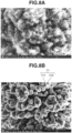
- Figs. 7A and 7B and Figs. 8A and 8B illustrate scanning electron microscope (SEM) photographs (photographs as substitutes for drawings) obtained by enlarging the surface of the member composed of tungsten before and after the heat treatment in the present exemplary embodiment.
- Fig. 7A illustrates an enlarged photograph of the surface of the member before the heat treatment
- Fig. 7B illustrates an enlarged photograph of the surface of the member after the heat treatment.
- the concave portions 721 of the second concavo-convex structure 72 were arranged in a honeycomb manner, and the depth of each concave portion 721 was 70 ⁇ m.
- Fig. 8A illustrates an SEM photograph (a photograph as a substitute for a drawing) obtained by further enlarging Fig. 7A
- Fig. 8B illustrates an SEM photograph (a photograph as a substitute for a drawing) obtained by further enlarging Fig. 7B
- the first concavo-convex structure 71 after the heat treatment was a structure where particles were deposited, and the distance L1 between the first convex portions 710 close to each other varied from 110 nm to 580 nm. The average of the distance L1 was 360 nm. The emissivity after the heat treatment was 0.55.
- the member was surface-treated under conditions similar to those in example 1-1 except that a plurality of holes was formed on the surface of the member so that the pitch P2 between the convex portions and/or the concave portions was 30 ⁇ m.
- the emissivity after the heat treatment was 0.86.
- the member was surface-treated under conditions similar to those in example 1-2 except that laser processing was performed in the atmospheric air.
- the first concavo-convex structure 71 after the heat treatment was a structure where particles were deposited, and the distance L1 between the first convex portions 710 close to each other varied from 100 nm to 590 nm.
- the average of the distance L1 was 310 nm.
- the emissivity after the heat treatment was 0.65.
- the member composed of tungsten was not surface-treated, and was only heat-treated.
- the surface of the member did not have first and second concavo-convex structures.
- the emissivity after the heat treatment was 0.08.
- Table 1 illustrates the processing conditions and the emissivity in examples 1-1 to 1-3 and comparative example.
- the emissivity was greatly improved by providing holes of a desired size. Particularly in example 1-2, the emissivity was more improved than in example 1-1 by making the pitch P2 in the second concavo-convex structure 72 small.
- laser processing was performed in a nitrogen environment to reduce the oxygen concentration.
- inert gas such as argon or helium, which does not form a compound that decreases the melting point or has a sublimation property by reaction with the target material, may be used.
- Example 1-1 Example 1-2
- Example 1-3 Comparative Example Processing atmosphere in nitrogen in nitrogen in atmospheric air - Pitch P1 110 nm - 580 nm 100 nm - 590 nm 160 nm - 520 nm Average of pitch P1 360 nm 310 nm 450 nm Pitch P2 40 ⁇ m 30 ⁇ m 30 ⁇ m 30 ⁇ m - Laser wavelength 1064 nm 1064 nm 1064 nm - Laser output 4 W 4 W 4 W 4 W - Pulse width 258 fs 258 fs 258 fs - Oscillation frequency 200 kHz 200 kHz 200 kHz - Irradiation time/hole 5000 ⁇ s 5000 ⁇ s 5000 ⁇ s 5000 ⁇ s - Heating treatment temperature in hydrogen 1100°C 1100°C 1100°C 1100°C Emissivity 0.55 0.86 0.65 0.08
- the first concavo-convex structure 71 was formed in the heat dissipation portion 20 using dry etching.
- Fig. 9A gold nanoparticles 102 were applied onto a member 101 composed of tungsten. Then, as illustrated in Fig. 9B , argon (Ar) ions 103 generated and accelerated by an Ar ion source were emitted, and the member 101 was dry-etched using the nanoparticles 102 as a mask. After the member 101 was processed to a depth of 900 nm, then as illustrated in Fig. 9C , the mask was removed, and the first concavo-convex structure 71 where the pitch P1 was 300 nm was formed in the member 101, thereby manufacturing the heat dissipation portion 20. The emissivity was 0.70.
- the first concavo-convex structure 71 is formed in the heat dissipation portion 20 composed of a high-melting-point metal, whereby it is possible to prevent a decrease in the emissivity even if the temperature of the heat dissipation portion 20 rises to near the melting point. That is, it is possible to maintain the emissivity even under a use environment at a high temperature and effectively utilize radiative cooling. It is also possible to form an etching mask using a photolithography process instead of the gold nanoparticles 102.
- a target used in an X-ray generation apparatus has been cited as a structural body.
- the structural body according to the present invention is not limited to this, and can be applied to various articles.
- the structural body can also be used in a housing surrounding an electronic component, as a method for letting out heat in an electronic device such as a personal computer (PC).
- the structural body may be obtained by providing concavo-convex structures as in the present invention on the surface of a heat dissipation sheet.
- the above exemplary embodiments can be appropriately changed without departing from their technical ideas.
- a plurality of exemplary embodiments can be combined together. Some items in at least one exemplary embodiment can be deleted or replaced. Further, a new item can be added to at least one exemplary embodiment.
- the disclosed content of the specification includes not only items explicitly described in the specification but also all items that can be understood from the specification and the drawings attached to the specification.
- the disclosed content of the specification includes a complement of individual concepts described in the specification. That is, for example, if the specification states that "A is larger than B", and even if the specification omits the statement that "A is not larger than B", the specification can be said to state that "A is not larger than B". This is because the statement that "A is larger than B" is based on the premise of the consideration that "A is not larger than B".
Landscapes
- Health & Medical Sciences (AREA)
- Life Sciences & Earth Sciences (AREA)
- Engineering & Computer Science (AREA)
- Medical Informatics (AREA)
- Physics & Mathematics (AREA)
- Molecular Biology (AREA)
- General Health & Medical Sciences (AREA)
- High Energy & Nuclear Physics (AREA)
- Nuclear Medicine, Radiotherapy & Molecular Imaging (AREA)
- Pathology (AREA)
- Radiology & Medical Imaging (AREA)
- Surgery (AREA)
- Heart & Thoracic Surgery (AREA)
- Biomedical Technology (AREA)
- Optics & Photonics (AREA)
- Animal Behavior & Ethology (AREA)
- Biophysics (AREA)
- Public Health (AREA)
- Veterinary Medicine (AREA)
- General Physics & Mathematics (AREA)
- Theoretical Computer Science (AREA)
- Pulmonology (AREA)
- Spectroscopy & Molecular Physics (AREA)
- Chemical & Material Sciences (AREA)
- Analytical Chemistry (AREA)
- Biochemistry (AREA)
- Immunology (AREA)
- X-Ray Techniques (AREA)
- Apparatus For Radiation Diagnosis (AREA)
- Analysing Materials By The Use Of Radiation (AREA)
Abstract
Description
- The present invention relates to a structural body, an X-ray generation apparatus, an X-ray computed tomography (CT) apparatus, and a manufacturing method for manufacturing a heat dissipation portion.
- To a component that reaches a high temperature when used, a technique for increasing the heat dissipation property may be applied to decrease an amount of the heat accumulated in the component. For example, there is a technique for increasing the light absorption rate and improving the heat dissipation property by composing the surface of the component of a black material or applying or thermal-spraying the black material to the surface of the component.
- International Patent Publication No.
WO2020/067075 discusses a form in which a fin is provided on the surface of an X-ray tube target. - In the form of International Patent Publication No.
WO2020/067075 , the heat dissipation property is not sufficient, and there is room for consideration of an improvement in the heat dissipation property on the surface of a component. - The present invention is directed to providing a structural body in which the heat dissipation property is improved.
- According to a first aspect of the present invention, there is provided a structural body as specified in claims 1 to 11. According to a second aspect of the present invention, there is provided an X-ray generation apparatus as specified in
claim 12. According to a third aspect of the present invention, there is provided an X-ray computed tomography (CT) apparatus as specified inclaim 13. According to a fourth aspect of the present invention, there is provided a manufacturing method as specified inclaims 14 to 15. - Further features of the present invention will become apparent from the following description of exemplary embodiments with reference to the attached drawings.
-
-
Fig. 1 is a schematic view of an X-ray generation apparatus (a rotating anode X-ray tube). -
Fig. 2A is an enlarged view illustrating an electron tube target and an electron emission source in the X-ray generation apparatus inFig. 1 , andFig. 2B is an enlarged view of a portion surrounded by a circle C inFig. 2A . -
Fig. 3 is a schematic diagram illustrating a laser processing machine for manufacturing a heat dissipation portion. -
Fig. 4 is a flowchart illustrating processes for laser-processing the heat dissipation portion. -
Fig. 5 is a schematic view of a computed tomography (CT) apparatus to which the X-ray generation apparatus according to a first exemplary embodiment is applied. -
Fig. 6 is a diagram illustrating a target according to a second exemplary embodiment. -
Fig. 7A illustrates an enlarged photograph of a surface of a member before heat treatment, andFig. 7B illustrates an enlarged photograph of the surface of the member after the heat treatment. -
Fig. 8A illustrates a scanning electron microscope (SEM) photograph (a photograph as a substitute for a drawing) obtained by further enlargingFig. 7A , andFig. 8B illustrates an SEM photograph (a photograph as a substitute for a drawing) obtained by further enlargingFig. 7B . -
Figs. 9A to 9C are diagrams illustrating the formation of a first concavo-convex structure in the heat dissipation portion using dry etching. - With reference to the drawings, a form for carrying out the present invention will be described below. The form described below, however, is an exemplary embodiment of the invention, and is not limited to this. Then, common components are described with reference to a plurality of drawings, and the descriptions of components designated by common signs are appropriately omitted. Different items with the same name can be distinguished from each other by adding "n-th" to the name as in a "first item" and a "second item".
- With reference to
Figs. 1 ,2A, and 2B , a structural body according to a first exemplary embodiment is described. The present exemplary embodiment illustrates an example where an electron tube target in an X-ray generation apparatus forms a structural body.Fig. 1 is a schematic view of an X-ray generation apparatus (a rotating anode X-ray tube).Fig. 2A is an enlarged view illustrating an electron tube target and an electron emission source in the X-ray generation apparatus inFig. 1 .Fig. 2B is an enlarged view of a portion surrounded by a circle C inFig. 2A . - In
Fig. 1 , anX-ray generation apparatus 100 includes anelectron emission source 11 provided in acathode assembly 12 and an electron tube target (hereinafter occasionally referred to simply as "target") 10 attached to ananode shaft 13. Theelectron emission source 11 forms a cathode, and thetarget 10 forms an anode. These members are stored in acontainer 14 in a vacuum state. Thetarget 10 is rotated together with theanode shaft 13 by, for example, a coil (not illustrated) provided outside thecontainer 14. - An
electron beam 15 emitted from theelectron emission source 11 is focused by a focusing electrode (not illustrated), and thetarget 10 is irradiated with theelectron beam 15. AnX-ray 16 is generated from thetarget 10 irradiated with theelectron beam 15, and the generatedX-ray 16 is emitted from thecontainer 14 to outside. - At this time, a part of the energy of the
electron beam 15 with which thetarget 10 is irradiated is used to generate theX-ray 16, but most of the energy is absorbed by thetarget 10 and raises the temperature of thetarget 10. - To emit an X-ray at a high output, it is necessary to irradiate the
target 10 with a large number of electron beams. This results in heating thetarget 10 to a high temperature. Thus, it is important to efficiently cool thetarget 10. However, since thetarget 10 is used in a vacuum, it is difficult to cool thetarget 10 using convection, and thetarget 10 is cooled using heat emission from thetarget 10 and heat conduction through theanode shaft 13. In the present exemplary embodiment, a structural body that efficiently emits heat is formed by providing a heat dissipation portion having concavo-convex structures in thetarget 10. - As a material forming the
target 10, a high-melting-point metal that not only facilitates the emission of theX-ray 16 but also has a high heat resistance is desirable. Moreover, to stabilize theX-ray 16 to be emitted, a high-melting-point metal having a large heat capacity is desirable so that changes in the temperature of thetarget 10 can be prevented while thetarget 10 is being irradiated with theelectron beam 15. Thus, it is desirable to use tungsten, molybdenum, niobium, tantalum, rhenium, hafnium, zirconium, or yttrium as the material of thetarget 10. - On the other hand, it is desirable that the inside of the
container 14 should be in a vacuum state. The degree of vacuum can be appropriately used from a low vacuum (a pressure of 1.0E-5 Pa) to an absolute vacuum (a pressure of 0 Pa) according to the purpose. For example, in the case of theX-ray generation apparatus 100 according to the present exemplary embodiment, it is desirable that the pressure should be 1.0E-4 Pa to 1.0E-6 Pa. -
Fig. 2A illustrates an enlarged view of a main portion of the X-ray generation apparatus illustrated inFig. 1 . As described above, thetarget 10 is irradiated with theelectron beam 15 from theelectron emission source 11. Then, theX-ray 16 is emitted from thetarget 10 irradiated with theelectron beam 15. On the other hand, heat is generated in an irradiatedarea 17 of thetarget 10 irradiated with theelectron beam 15, and thetarget 10 enters a high-temperature state at 1000°C or more. Thus, in the present exemplary embodiment, aheat dissipation portion 20 having concavo-convex structures illustrated inFig. 2B is provided on the external surface of thetarget 10 and dissipates at least a part of the heat generated in the irradiatedarea 17. Theheat dissipation portion 20 may be provided in the entirety or a part of the external surface of thetarget 10. The irradiatedarea 17 of thetarget 10 irradiated with theelectron beam 15 corresponds to "a component that can be a heat source". Since theelectron beam 15 generates heat, the irradiatedarea 17 and theelectron emission source 11 that emits theelectron beam 15 to the irradiatedarea 17 can also be collectively regarded as "a component that can be a heat source". - Next, the structure of the
heat dissipation portion 20 is described.Fig. 2B is an enlarged view of a portion surrounded by a circle C inFig. 2A . As illustrated inFig. 2B , the surface of theheat dissipation portion 20 according to the present exemplary embodiment has a first concavo-convex structure 71 where a plurality of firstconvex portions 710 and a plurality of firstconcave portions 711 are alternately arranged. The first concavo-convex structure 71 is formed so that the distance between firstconvex portions 710 close to each other among the plurality of firstconvex portions 710 and/or the distance between firstconcave portions 711 close to each other among the plurality of firstconcave portions 711 is a constant pitch P1. The distance between the firstconvex portions 710 close to each other is the distance from the top of a certainconvex portion 710 to the top of aconvex portion 710 close to the certainconvex portion 710. Similarly, the distance between the firstconcave portions 711 close to each other is the distance from the bottom of a certainconcave portion 711 to the bottom of aconcave portion 711 close to the certainconcave portion 711. On the surface of theheat dissipation portion 20, a second concavo-convex structure 72 where a plurality of secondconvex portions 720 and a plurality of secondconcave portions 721 are alternately arranged is also formed. The second concavo-convex structure 72 is formed so that the distance between secondconvex portions 720 close to each other among the plurality of secondconvex portions 720 and/or the distance between secondconcave portions 721 close to each other among the plurality of secondconcave portions 721 is a constant pitch P2. The pitch P2 is longer than the pitch P1, and the first concavo-convex structure 71 is formed on the surface of the second concavo-convex structure 72. - In the present exemplary embodiment, an example has been illustrated where the pitches P1 and P2 are constant. However, the distance between the first
convex portions 710 close to each other and/or the distance between the firstconcave portions 711 close to each other (hereinafter referred to as a "distance L1") does not necessarily need to be constant. Similarly, the distance between the secondconvex portions 720 close to each other and/or the distance between the secondconcave portions 721 close to each other (hereinafter referred to as a "distance L2") does not necessarily need to be constant. In this case, the first concavo-convex structure 71 and the second concavo-convex structure 72 are formed so that the shortest distance among the distances L2 is longer than the longest distance among the distances L1. - In the present exemplary embodiment, the first concavo-
convex structure 71 is formed so that the distance L1 between the firstconvex portions 710 close to each other and/or the distance L1 between the firstconcave portions 711 close to each other in the first concavo-convex structure 71 is less than half (1/2) of the peak wavelength of the electromagnetic wave of the heat emitted from theheat dissipation portion 20. This configuration improves the heat dissipation property of theheat dissipation portion 20. If, on the other hand, the distance L1 is greater than or equal to half (1/2) of the peak wavelength of the electromagnetic wave of the heat emitted from theheat dissipation portion 20, the heat dissipation property of theheat dissipation portion 20 decreases. The reason is considered as follows. As will be described below, to efficiently emit an electromagnetic wave at a wavelength λ generated by heat emission, a structure capable of, if an electromagnetic wave having the same wavelength λ as this electromagnetic wave is incident on the structure, absorbing the electromagnetic wave without reflecting the electromagnetic wave may be considered. - If the first concavo-
convex structure 71 is regarded as a diffraction grating, the electromagnetic waves does not interfere with each other in the diffraction grating under the condition that the pitch P1 between the firstconvex portions 710 and/or the firstconcave portions 711 is less than or equal to half of the wavelength λ. This is a so-called subwavelength structure (hereinafter referred to as "SWS") and is a structure that does not reflect the electromagnetic wave at the wavelength λ. - The peak wavelength of the electromagnetic wave changes due to the temperature of a heating element that emits heat, i.e., the temperature of the target 10 (particularly, the heat dissipation portion 20) in the present exemplary embodiment, and is 3.00 µm at 700°C, 2.47 µm at 900°C, 1.84 µm at 1300°C, 1.63 µm at 1500°C, and 1.55 µm at 1600°C, for example. Thus, it is desirable to set the distance L1 between the first
convex portions 710 close to each other and/or the distance L1 between the firstconcave portions 711 close to each other in the first concavo-convex structure 71 according to the use situation of thetarget 10. For example, in a case where thetarget 10 is used in a situation where the temperature of theheat dissipation portion 20 is 700°C, the distance L1 may be less than 1/2 of 3.00 µm. That is, it is desirable to form the first concavo-convex structure 71 so that the distance L1 is 50 nm or more and less than 1500 nm. For example, in a case where thetarget 10 is used in a situation where the temperature of theheat dissipation portion 20 is 900°C to 1300°C, it is desirable to set the distance L1 based on the peak wavelength at 1300°C, which is the higher temperature. It is more desirable that the distance L1 should be less than 1/4 of the peak wavelength of the electromagnetic wave of the emitted heat. For example, it is desirable that the distance L1 should be 200 nm or more and 600 nm or less. - In contrast, the distance L2 between the second
convex portions 720 close to each other and/or the distance L2 between the secondconcave portions 721 close to each other in the second concavo-convex structure 72 may be greater than the distance L1 in the first concavo-convex structure 71. For example, it is desirable that the distance L2 should be 1 µm or more and 100 µm or less. It is more desirable that the distance L2 should be 10 µm or more and 50 µm or less. This can improve the heat dissipation property of theheat dissipation portion 20. The depth ofconcave portions 721 and/or the heigh ofconvex portions 720 may be 1 µm or more and 150 µm or less, and may be 10 µm or more and 100 µm or less. - A description is given below of the heat dissipation property of the
heat dissipation portion 20 in which the first concavo-convex structure 71 and the second concavo-convex structure 72 are provided. The heat dissipation property of theheat dissipation portion 20 is correlated with the absorption property of theheat dissipation portion 20. It can be said that a heat dissipation portion having a high absorption property also has a high heat dissipation property.Fig. 2B illustrates anelectromagnetic wave 73 incident on theheat dissipation portion 20, anelectromagnetic wave 74 reflected by theheat dissipation portion 20, and anelectromagnetic wave 75 penetrating in (and that may be absorbed in) theheat dissipation portion 20. If the pitch P1 between the firstconvex portions 710 and/or the firstconcave portions 711 in the first concavo-convex structure 71 is less than 1/2 of the peak wavelength of the emitted electromagnetic wave, the reflection of theelectromagnetic wave 73 incident on theheat dissipation portion 20 is reduced due to the effect of the SWS, and it is possible to significantly improve the absorption rate of theelectromagnetic wave 73. Thus, based on the above relationship between the absorption property and the heat dissipation property, it is possible to improve the heat dissipation property using the first concavo-convex structure 71. - On the other hand, a part of the
electromagnetic wave 73 incident on theheat dissipation portion 20 is reflected into the secondconcave portions 721. The reflection of the reflectedelectromagnetic wave 74 is prevented due to the effect of the SWS by the first concavo-convex structure 71 formed on the surface of the second concavo-convex structure 72, but a part of the reflectedelectromagnetic wave 74 is further reflected into the secondconcave portions 721. As described above, it is possible to significantly reduce the reflectance due to the effects of the first concavo-convex structure 71 (the SWS) on the surface and the holes of the second concavo-convex structure 72. The reduction in the reflectance leads to an increase in the absorption rate, and as described above, there is a relationship where a heat dissipation portion having a high absorption rate also has a high heat dissipation property. Thus, it is possible to further increase the heat dissipation property by providing the second concavo-convex structure 72. - Such a heat dissipation property improvement mechanism also applies to a case where the distance L1 between the first
convex portions 710 close to each other and/or the distance L1 between the firstconcave portions 711 close to each other is not constant as in the pitch P1. Also in a case where the distance L2 between the secondconvex portions 720 close to each other and/or the distance L2 between the secondconcave portions 721 close to each other is not constant as in the pitch P2, it is possible to similarly improve the heat dissipation property. In the present exemplary embodiment, an example has been illustrated where the first concavo-convex structure 71 is formed on the surface of the second concavo-convex structure 72. The second concavo-convex structure 72, however, does not necessarily need to be provided, and it is possible to improve the heat dissipation property due to the effect of the SWS so long as the first concavo-convex structure 71 is formed. - The shapes of the first
convex portions 710 and/or the firstconcave portions 711 forming the first concavo-convex structure 71 are not particularly limited. It is, however, desirable that the firstconvex portions 710 should be formed of particles attached to the surface of theheat dissipation portion 20. The firstconvex portions 710 have shapes in which particles are deposited, whereby the surface area of the firstconvex portions 710 is greater than that of another shape, and it is possible to improve the absorption rate of the electromagnetic wave. Particularly, in thetarget 10 used under a use environment at 1000°C or more, it is easy to form the first concavo-convex structure 71 where the pitch P1 is short by aggregating particles, and the effect of using the first concavo-convex structure 71 in combination with the second concavo-convex structure 72 also increases. When the first concavo-convex structure 71 has a form in which particles are deposited, the particle size of the particles can be regarded as equivalent to the pitch P1 in the first concavo-convex structure 71. Thus, the first concavo-convex structure 71 is formed so that the particle size of the particles forming the first concavo-convex structure 71 is smaller than 1/2 of the peak wavelength of the emitted electromagnetic wave. - Similarly, the depth of the first concavo-
convex structure 71 can be regarded as equivalent to the particle size of the particles. - It is desirable that the first concavo-
convex structure 71 should be formed of a metal having a high X-ray emission efficiency, a high melting point, and a large heat capacity. The metal having a high melting point is a metal having a melting point of 1500°C or more. As such a metal, tungsten is desirable, and molybdenum, niobium, tantalum, rhenium, hafnium, zirconium, or yttrium, which has a large heat capacity, is also suitable. - In a case where the first concavo-
convex structure 71 is formed of a metal having a high melting point, it is desirable that the amount of nitrogen contained in a portion from the surface to a depth of 100 nm or less in the first concavo-convex structure 71 should be 1 at% (where "at%" signifies atomic percentage) or more, or the amount of oxygen contained in the portion should be 10 at% or less. For example, in a case where the first concavo-convex structure 71 is processed by a method as described below, and if the first concavo-convex structure 71 is processed under a nitrogen atmosphere, 1 at% or more of nitrogen is incorporated into the surface and contributes to an improvement in the emissivity. If a large amount of oxygen is included in the high-melting-point metal, the melting point may decrease. Thus, it is desirable that the amount of contained oxygen should be 10 at% or less. The amount of contained nitrogen and the amount of contained oxygen do not necessarily need to be in the above ranges, and may be in appropriate ranges according to the purpose. - Next, with reference to
Figs. 3 and4 , a manufacturing method for manufacturing theheat dissipation portion 20 according to the present exemplary embodiment is described.Fig. 3 is a schematic diagram illustrating alaser processing machine 110 for manufacturing theheat dissipation portion 20. The surface of a member such as thetarget 10 according to the present exemplary embodiment is processed to partially remove a metal of the member with laser light using the laser processing machine 110 (i.e. laser ablation), thereby processing theheat dissipation portion 20 into a shape like the second concavo-convex structure 72 (hereinafter, thetarget 10 will occasionally be referred to as a "processing target member" in the sense that thetarget 10 is a member in which theheat dissipation portion 20 is formed). On the other hand, a metal removed from the processing target member becomes metal particles, and the metal particles deposit on the surface of the second concavo-convex structure 72, thereby forming the first concavo-convex structure 71 (seeFig. 2B ). Thus, the distance L1 between the firstconvex portions 710 close to each other and/or the distance L1 between the firstconcave portions 711 close to each other in the first concavo-convex structure 71 is not constant. Further, the particle size of the deposited metal particles does not need to be constant. It is desirable that there should be particles in which the difference between the maximum particle size and the minimum particle size is 300 nm or more. This can randomly cause reflection in the first concavo-convex structure 71 and improve the absorption rate of the first concavo-convex structure 71. It is desirable that the particle size of the particles should be 50 nm or more and less than 1500 nm. Thus, it is desirable that the depth of the first concavo-convex structure 71 should also be 50 nm or more and less than 1500 nm. - In the
laser processing machine 110 illustrated inFig. 3 , the beam diameter of laser light emitted from alaser oscillator 111 is enlarged by abeam expander 112. Then, the laser light is reflected by agalvanometer mirror 113, is incident on anFθ lens 114, and is collected on the target (processing target member) 10 in which theheat dissipation portion 20 is formed. The target (processing target member) 10 is fixed to a fixing table 116 and can be freely moved using amovable stage 117. - A
galvanometer control unit 118 controls thelaser oscillator 111 and thegalvanometer mirror 113. -
Fig. 3 illustrates an example where asingle galvanometer mirror 113 is provided. However, in a case where laser light is controlled in two axial directions, two mirrors are required. The number of mirrors can be appropriately selected according to the purpose. - A
stage control unit 119 controls themovable stage 117. In a case where autofocus is performed, based on a signal from a displacement meter (not illustrated), thestage control unit 119 controls themovable stage 117 to move up and down so that the distance between the laser light collection position and the target (processing target member) 10 is constant. Ahost computer 120 includes a user interface and a processing data storage unit and can control thegalvanometer control unit 118 and thestage control unit 119 in conjunction with each other at a predetermined timing. Although not illustrated, themovable stage 117 and the target (processing target member) 10 are installed in an environment box, and laser processing can be performed in an environment where the oxygen concentration is controlled to be 0.5% or less. - Next, with reference to a flowchart illustrated in
Fig. 4 , processes for laser-processing theheat dissipation portion 20 according to the present exemplary embodiment are described. First, after the target (processing target member) 10 is fixed onto the fixing table 116, position information required for the processing is acquired by reading an alignment mark, and the laser processing position is corrected, thereby making preparations for the processing. - In the flowchart in
Fig. 4 , first, in step S21, thestage control unit 119 is instructed to move the fixing table 116 to a desired position. Next, in step S22, processing position data, a galvanometer mirror stop time, and laser processing conditions are indicated to thegalvanometer control unit 118. In step S23, the completion of the movement of themovable stage 117 is confirmed. In step S24, the processing is started. In the processing process, first, in step S25, in the state where the oscillation of the laser is suspended, thegalvanometer mirror 113 is driven so that laser light is emitted to a desired position when the laser is oscillated. Next, in step S26, the end of the driving of thegalvanometer mirror 113 is confirmed. Then, in step S27, thegalvanometer mirror 113 is stopped and kept waiting for the time set in advance. Next, in step S28, the laser is oscillated, and the second concavo-convex structure 72 is processed. During the processing, the target (processing target member) 10 is irradiated with laser light emitted from the laser for a desired time or with a desired number of pulses. Next, in step S29, the completion of the processing of a single secondconcave portion 721 is confirmed (seeFig. 2B ), and the oscillation of the laser is suspended. Next, in step S30, it is determined whether all the processing of an area that can be processed by thegalvanometer mirror 113 ends. Then, if all the processing does not end (No in step S30), the operation returns to step S25, and the processing is continued. If, on the other hand, all the processing of the area that can be processed by thegalvanometer mirror 113 ends (Yes in step S30), the processing of the above area ends. If theheat dissipation portion 20 can be manufactured only by the processing of the above area, the manufacturing processes end. If, however, another area needs to be processed, the operation returns to the process of step S21. - In the present exemplary embodiment, using the
laser processing machine 110, it is possible to form concavo-convex structures at predetermined positions on the surface of the target (processing target member) 10 by preventing oxidation. If a femtosecond laser is used as thelaser oscillator 111, it is also possible to laser-process a high-melting-point metal such as tungsten or molybdenum by preventing oxidation. As described above, evaporated molecules of the target (processing target member) 10 evaporated by irradiating the target (processing target member) 10 with laser light for a desired time or with a desired number of pulses are aggregated in a gas phase and attached as particles to the surface of the target (processing target member) 10. The attached particles form an SWS and can improve the emissivity of thetarget 10. It is desirable that the SWS should be a concavo-convex structure where the pitch and/or the distance between convex portions (the distance between concave portions) is less than 1/2 of the peak wavelength of the electromagnetic wave of emitted heat, and should be a structure having a depth three times or more the pitch and/or the distance. With this structure, a change in the depth direction of the refractive index of an interface relative to the peak wavelength of the electromagnetic wave of the emitted heat is gradual, whereby it is possible to effectively prevent the reflection of the electromagnetic wave and improve the emissivity. Even in a case where the function of the SWS as the first concavo-convex structure 71 is insufficient, the first concavo-convex structure 71 is used in combination with the second concavo-convex structure 72, whereby it is possible to improve the emissivity. Further, although the oxidation of the processed surface may decrease a melting point of the processed surface, it is possible to prevent the oxidation of the processed surface by using thelaser processing machine 110, and therefore, also when the temperature of thetarget 10 composed of a high-melting-point metal rises to near the melting point, it is possible to prevent a fine structure from being lost due to melting in the decreased melting point of the processed surface and prevent a decrease in the emissivity. That is, it is possible to maintain the emissivity even under a use environment where thetarget 10 reaches a high temperature, and effectively utilize radiative cooling. - In the present exemplary embodiment, a description has been given of a form in which the
heat dissipation portion 20 is processed by intermittently stopping thegalvanometer mirror 113. Alternatively, the processing may be performed by continuously scanning laser light while causing the laser light to blink without stopping thegalvanometer mirror 113. - For example, the
X-ray generation apparatus 100 according to the present exemplary embodiment can be used in an X-ray computed tomography (CT) apparatus illustrated inFig. 5. Fig. 5 is a cross-sectional view of anX-ray CT apparatus 600. TheX-ray CT apparatus 600 includes astator 200 and arotor 150 and is configured so that therotor 150 rotates about a Z-axis as a rotational axis relative to thestator 200. - The
X-ray CT apparatus 600 includes a plate-like portion 201, anX-ray emission unit 202, anX-ray detection unit 203, asignal amplification unit 204, acooling unit 205, apower supply unit 206, and a powersupply control unit 207. Each of the plate-like portion 201, theX-ray emission unit 202, theX-ray detection unit 203, thesignal amplification unit 204, thecooling unit 205, thepower supply unit 206, and the powersupply control unit 207 is a component installed in therotor 150. - The plate-
like portion 201 is an annular plate-like member installed inside thecylindrical rotor 150. In the center of the plate-like portion 201, animaging opening 208 into which a subject such as a human being or another living object as a target of X-ray CT is inserted is provided. - The form of inserting the subject into the
imaging opening 208 is not particularly limited. For example, the subject is inserted into theimaging opening 208 by sliding a bed (not illustrated) on which the subject lies into theimaging opening 208 along the Z-direction of theimaging opening 208. The subject is not necessarily limited to a living object such as a human being, and may be an article such as an industrial product. - Each of the
X-ray emission unit 202, theX-ray detection unit 203, thesignal amplification unit 204, thecooling unit 205, thepower supply unit 206, and the powersupply control unit 207 is installed by being attached to one surface of the plate-like portion 201 in the Z-direction. TheX-ray emission unit 202, theX-ray detection unit 203, thesignal amplification unit 204, thecooling unit 205, thepower supply unit 206, and the powersupply control unit 207 rotate about the Z-axis as a rotational axis by the rotation of the plate-like portion 201 associated with the rotation of therotor 150 by a rotational driving apparatus (not illustrated). These units may be attached to one or the other surface or both surfaces of the plate-like portion 201 in the Z-direction. These units may be placed between a plurality of coil rows. - The
X-ray emission unit 202 and theX-ray detection unit 203 are installed on the same surface of the plate-like portion 201 in the Z-direction. TheX-ray emission unit 202 and theX-ray detection unit 203 are placed to be opposed to each other across the Z-axis as the rotational axis of the annular plate-like portion 201 in the diameter direction of the annular plate-like portion 201. - The
X-ray emission unit 202 is an emission unit that emits an X-ray as radiation toward the subject while therotor 150 rotates around the subject once. For example, theX-ray emission unit 202 is theX-ray generation apparatus 100. Thepower supply unit 206 is a power supply apparatus that supplies a voltage for emitting the X-ray, such as a tube voltage for an X-ray tube, to theX-ray emission unit 202. The powersupply control unit 207 is a control apparatus that controls the supply of the tube voltage from thepower supply unit 206. Thecooling unit 205 is a cooling apparatus that cools theX-ray emission unit 202 that generates heat when emitting the X-ray. - The
X-ray detection unit 203 is a detector that detects the X-ray emitted from theX-ray emission unit 202 toward the subject and being transmitted through (passing through) the subject. TheX-ray detection unit 203 outputs a detection signal according to the detected X-ray. Thesignal amplification unit 204 amplifies the detection signal output from theX-ray detection unit 203. - The
signal amplification unit 204 outputs the amplified detection signal to a system control unit (not illustrated). The system control unit generates an X-ray CT image by image processing based on the detection signal from thesignal amplification unit 204. - With reference to
Fig. 6 , thetarget 10 according to a second exemplary embodiment is described. Theheat dissipation portion 20 according to the present exemplary embodiment is different from that according to the first exemplary embodiment in that only the first concavo-convex structure 71 is formed, and the second concavo-convex structure 72 is not formed. - In the present exemplary embodiment,
Fig. 6 is an enlarged view of the range surrounded by the circle C inFig. 2A . Even in a case where the second concavo-convex structure 72 is not included as described above, it is possible to improve the heat dissipation property using the first concavo-convex structure 71 alone. The mechanism for improving the heat dissipation property using the first concavo-convex structure 71 is similar to that in the first exemplary embodiment. - The
heat dissipation portion 20 according to the present exemplary embodiment can be produced using thelaser processing machine 110 illustrated inFig. 3 similarly to the first exemplary embodiment. In the present exemplary embodiment, however, the first concavo-convex structure 71 is formed by processing the surface of the target (processing target member) 10 to a desired depth with laser light, instead of depositing molecules evaporated with laser light as in the first exemplary embodiment. Thus, regarding the first concavo-convex structure 71 according to the present exemplary embodiment, it is possible to set the distance L1 between the firstconvex portions 710 close to each other and/or the distance L1 between the firstconcave portions 711 close to each other to a constant value as in the pitch P1. The first concavo-convex structure 71 according to the present exemplary embodiment may be formed by lithography (dry etching using a mask), instead of laser processing. Further, as the formation method for forming the first concavo-convex structure 71, a method for depositing particles on the surface of the target (processing target member) 10 by physical vapor deposition or chemical vapor deposition can also be used. - Next, the present invention is described in further detail by citing targets formed under various processing conditions as examples and a comparative example. The present invention, however, is not limited to the following examples.
- In example 1-1, a member composed of tungsten was surface-treated using the
laser processing machine 110 described with reference toFig. 3 . Nitrogen gas was supplied into the environment box of thelaser processing machine 110, and the member composed of tungsten was installed under a nitrogen environment where the oxygen concentration was maintained at 0.5% or less. The processing conditions were a laser wavelength of 1064 nm, a laser output of 4 W, a pulse width of 258 fs, and an oscillation frequency of 200 kHz. A plurality of holes was formed on the surface of the member so that the pitch P2 between the convex portions and/or the concave portions was 40 µm. The irradiation time per hole was 5000 µs. The second concavo-convex structure 72 was formed of this series of holes, and the first concavo-convex structure 71 was formed by the deposition of the member (particles) produced by laser processing (seeFig. 2B ). After the deposition of the particles, heat treatment at 1100°C was performed in hydrogen, thereby reducing oxygen incorporated into the surface of the member and stabilizing the structures under a use environment at a high temperature. This treatment is performed, whereby it is possible to stably obtain a high emissivity even under a use environment at a high temperature of 1000°C or more. It is desirable to perform the heat treatment at 800°C or more. -
Figs. 7A and 7B andFigs. 8A and 8B illustrate scanning electron microscope (SEM) photographs (photographs as substitutes for drawings) obtained by enlarging the surface of the member composed of tungsten before and after the heat treatment in the present exemplary embodiment.Fig. 7A illustrates an enlarged photograph of the surface of the member before the heat treatment, andFig. 7B illustrates an enlarged photograph of the surface of the member after the heat treatment. As illustrated inFigs. 7A and 7B , theconcave portions 721 of the second concavo-convex structure 72 were arranged in a honeycomb manner, and the depth of eachconcave portion 721 was 70 µm. -
Fig. 8A illustrates an SEM photograph (a photograph as a substitute for a drawing) obtained by further enlargingFig. 7A , andFig. 8B illustrates an SEM photograph (a photograph as a substitute for a drawing) obtained by further enlargingFig. 7B . The first concavo-convex structure 71 after the heat treatment was a structure where particles were deposited, and the distance L1 between the firstconvex portions 710 close to each other varied from 110 nm to 580 nm. The average of the distance L1 was 360 nm. The emissivity after the heat treatment was 0.55. - In example 1-2, the member was surface-treated under conditions similar to those in example 1-1 except that a plurality of holes was formed on the surface of the member so that the pitch P2 between the convex portions and/or the concave portions was 30 µm.The emissivity after the heat treatment was 0.86.
- In example 1-3, the member was surface-treated under conditions similar to those in example 1-2 except that laser processing was performed in the atmospheric air. The first concavo-
convex structure 71 after the heat treatment was a structure where particles were deposited, and the distance L1 between the firstconvex portions 710 close to each other varied from 100 nm to 590 nm. The average of the distance L1 was 310 nm. The emissivity after the heat treatment was 0.65. - In comparative example, the member composed of tungsten was not surface-treated, and was only heat-treated.
- Thus, the surface of the member did not have first and second concavo-convex structures. The emissivity after the heat treatment was 0.08.
- Table 1 illustrates the processing conditions and the emissivity in examples 1-1 to 1-3 and comparative example. The emissivity was greatly improved by providing holes of a desired size. Particularly in example 1-2, the emissivity was more improved than in example 1-1 by making the pitch P2 in the second concavo-
convex structure 72 small. - In examples 1-1 and 1-2, laser processing was performed in a nitrogen environment to reduce the oxygen concentration. Alternatively, inert gas such as argon or helium, which does not form a compound that decreases the melting point or has a sublimation property by reaction with the target material, may be used.
Table 1 List of control commands Example 1-1 Example 1-2 Example 1-3 Comparative Example Processing atmosphere in nitrogen in nitrogen in atmospheric air - Pitch P1 110 nm - 580 nm 100 nm - 590 nm 160 nm - 520 nm Average of pitch P1 360 nm 310 nm 450 nm Pitch P2 40 µm 30 µm 30 µm - Laser wavelength 1064 nm 1064 nm 1064 nm - Laser output 4 W 4 W 4 W - Pulse width 258 fs 258 fs 258 fs - Oscillation frequency 200 kHz 200 kHz 200 kHz - Irradiation time/hole 5000 µs 5000 µs 5000 µs - Heating treatment temperature in hydrogen 1100°C 1100°C 1100°C 1100°C Emissivity 0.55 0.86 0.65 0.08 - In example 2, the first concavo-
convex structure 71 was formed in theheat dissipation portion 20 using dry etching. - As illustrated in
Fig. 9A ,gold nanoparticles 102 were applied onto amember 101 composed of tungsten. Then, as illustrated inFig. 9B , argon (Ar)ions 103 generated and accelerated by an Ar ion source were emitted, and themember 101 was dry-etched using thenanoparticles 102 as a mask. After themember 101 was processed to a depth of 900 nm, then as illustrated inFig. 9C , the mask was removed, and the first concavo-convex structure 71 where the pitch P1 was 300 nm was formed in themember 101, thereby manufacturing theheat dissipation portion 20. The emissivity was 0.70. - The first concavo-
convex structure 71 is formed in theheat dissipation portion 20 composed of a high-melting-point metal, whereby it is possible to prevent a decrease in the emissivity even if the temperature of theheat dissipation portion 20 rises to near the melting point. That is, it is possible to maintain the emissivity even under a use environment at a high temperature and effectively utilize radiative cooling. It is also possible to form an etching mask using a photolithography process instead of thegold nanoparticles 102. - In the above exemplary embodiments, a target used in an X-ray generation apparatus has been cited as a structural body. The structural body according to the present invention, however, is not limited to this, and can be applied to various articles. For example, the structural body can also be used in a housing surrounding an electronic component, as a method for letting out heat in an electronic device such as a personal computer (PC). Alternatively, the structural body may be obtained by providing concavo-convex structures as in the present invention on the surface of a heat dissipation sheet. The above exemplary embodiments can be appropriately changed without departing from their technical ideas. A plurality of exemplary embodiments can be combined together. Some items in at least one exemplary embodiment can be deleted or replaced. Further, a new item can be added to at least one exemplary embodiment.
- The disclosed content of the specification includes not only items explicitly described in the specification but also all items that can be understood from the specification and the drawings attached to the specification. The disclosed content of the specification includes a complement of individual concepts described in the specification. That is, for example, if the specification states that "A is larger than B", and even if the specification omits the statement that "A is not larger than B", the specification can be said to state that "A is not larger than B". This is because the statement that "A is larger than B" is based on the premise of the consideration that "A is not larger than B".
- Based on the structural body according to the present invention, it is possible to improve the heat dissipation property.
- While the present invention has been described with reference to exemplary embodiments, it is to be understood that the invention is not limited to the disclosed exemplary embodiments. The scope of the following claims is to be accorded the broadest interpretation so as to encompass all equivalent structures and functions.
Claims (15)
- A structural body heated to 700°C or more, the structural body comprising:a heat dissipation portion configured to dissipate heat of the structural body,wherein, on a surface of the heat dissipation portion, a first concavo-convex structure is provided where a plurality of first convex portions and a plurality of first concave portions are alternately arranged,wherein, when the structural body is heated to 700°C or more, a peak wavelength of an electromagnetic wave of heat emitted from the heat dissipation portion is 3 µm or less, andwherein a distance between first convex portions close to each other among the plurality of first convex portions, and/or a distance between first concave portions close to each other among the plurality of first concave portions, is less than half of the peak wavelength.
- The structural body according to claim 1, wherein the structural body forms an electron tube target, and the heat dissipation portion includes an area of the electron tube target irradiated with an electron and has the first concavo-convex structure on at least a part of a surface of the electron tube target.
- The structural body according to claim 1 or 2, wherein the heat dissipation portion and the first concavo-convex structure are composed of a metal having a melting point of 1500°C or more.
- The structural body according to any one of claims 1 to 3, further comprising, on the surface of the heat dissipation portion, a second concavo-convex structure where a plurality of second convex portions and a plurality of second concave portions are alternately arranged,wherein a distance between second convex portions close to each other among the plurality of second convex portions is longer than the distance between the first convex portions and/or a distance between second concave portions close to each other among the plurality of second concave portions is longer than the distance between the first concave portions, andwherein the first concavo-convex structure is provided on a surface of the second concavo-convex structure.
- The structural body according to claim 4, wherein the second concavo-convex structure is composed of a metal having a melting point of 1500°C or more.
- The structural body according to claim 4 or 5, wherein the distance between the second convex portions and/or the distance between the second concave portions is 10 µm or more.
- The structural body according to any one of claims 1 to 6, wherein the distance between the first convex portions and/or the distance between the first concave portions is 50 nm or more.
- The structural body according to any one of claims 1 to 7, wherein a depth of the first concavo-convex structure is 50 nm or more and less than 1500 nm.
- The structural body according to any one of claims 1 to 8, wherein the first concavo-convex structure includes particles, and a particle size of the particles is 50 nm or more and less than 1500 nm.
- The structural body according to any one of claims 1 to 9, wherein the heat dissipation portion is located in a vacuum.
- The structural body according to claim 10, further comprising an electron emission source configured to emit an electron to the area.
- An X-ray generation apparatus comprising:the structural body according to claim 11; anda container storing the structural body inside.
- An X-ray computed tomography (CT) apparatus comprising:the X-ray generation apparatus according to claim 12; anddetection means for detecting an X-ray emitted from the X-ray generation apparatus.
- A manufacturing method for manufacturing, on a surface of a member, a heat dissipation portion having a first concavo-convex structure where a plurality of first convex portions and a plurality of first concave portions are alternately arranged, the manufacturing method comprising:processing for processing the surface of the member with laser light; anddeposition for depositing a part of the member processed in the processing on the surface, thereby forming the first concavo-convex structure,wherein a distance between first convex portions close to each other among the plurality of first convex portions, and/or a distance between first concave portions close to each other among the plurality of first concave portions, is less than half of a peak wavelength of an electromagnetic wave of heat emitted from the heat dissipation portion.
- The manufacturing method according to claim 14,wherein in the processing, a second concavo-convex structure where a plurality of second convex portions and a plurality of second concave portions are alternately arranged is formed on the surface of the member,wherein a distance between second convex portions close to each other among the plurality of second convex portions is longer than the distance between the first convex portions, or a distance between second concave portions close to each other among the plurality of second concave portions is longer than the distance between the first concave portions, andwherein the first concavo-convex structure is provided on a surface of the second concavo-convex structure.
Applications Claiming Priority (1)
| Application Number | Priority Date | Filing Date | Title |
|---|---|---|---|
| JP2023027317A JP7805977B2 (en) | 2023-02-24 | 2023-02-24 | Structure, X-ray generating device, and method for manufacturing heat dissipation unit |
Publications (2)
| Publication Number | Publication Date |
|---|---|
| EP4421841A2 true EP4421841A2 (en) | 2024-08-28 |
| EP4421841A3 EP4421841A3 (en) | 2025-04-09 |
Family
ID=89984583
Family Applications (1)
| Application Number | Title | Priority Date | Filing Date |
|---|---|---|---|
| EP24158379.8A Pending EP4421841A3 (en) | 2023-02-24 | 2024-02-19 | Structural body, x-ray generation apparatus, x-ray computed tomography (ct) apparatus, and manufacturing method for manufacturing heat dissipation portion |
Country Status (4)
| Country | Link |
|---|---|
| US (1) | US20240292509A1 (en) |
| EP (1) | EP4421841A3 (en) |
| JP (1) | JP7805977B2 (en) |
| CN (1) | CN118555719A (en) |
Citations (1)
| Publication number | Priority date | Publication date | Assignee | Title |
|---|---|---|---|---|
| WO2020067075A1 (en) | 2018-09-26 | 2020-04-02 | 株式会社 東芝 | Rotating anode x-ray tube target, x-ray tube, and x-ray inspection device |
Family Cites Families (16)
| Publication number | Priority date | Publication date | Assignee | Title |
|---|---|---|---|---|
| JPS52115684A (en) * | 1976-10-05 | 1977-09-28 | Toshiba Corp | X-ray tube |
| JPS6229034A (en) * | 1985-07-31 | 1987-02-07 | Toshiba Corp | Manufacture of electron tube parts with black film |
| US5541975A (en) * | 1994-01-07 | 1996-07-30 | Anderson; Weston A. | X-ray tube having rotary anode cooled with high thermal conductivity fluid |
| JPH08129980A (en) * | 1994-10-28 | 1996-05-21 | Shimadzu Corp | Anode for X-ray tube |
| JP4206329B2 (en) | 2003-11-26 | 2009-01-07 | 株式会社リガク | X-ray tube |
| US20090147361A1 (en) * | 2007-12-07 | 2009-06-11 | 3M Innovative Properties Company | Microreplicated films having diffractive features on macro-scale features |
| JP2010118283A (en) | 2008-11-14 | 2010-05-27 | Hitachi Medical Corp | Rotating anode x-ray tube device, and x-ray ct device using the same |
| JP5252586B2 (en) * | 2009-04-15 | 2013-07-31 | ウシオ電機株式会社 | Laser drive light source |
| JP5468911B2 (en) * | 2010-01-05 | 2014-04-09 | 株式会社日立メディコ | X-ray tube apparatus and X-ray CT apparatus using the same |
| WO2013050570A1 (en) * | 2011-10-05 | 2013-04-11 | Lightlab Sweden Ab | Method for manufacturing nanostructures and cathode for field emission lighting arrangement |
| CN104520962A (en) * | 2012-05-24 | 2015-04-15 | 量子技术(德国)有限公司 | Cooled stationary anode for an x-ray tube |
| JP6594479B2 (en) | 2013-12-06 | 2019-10-23 | キヤノン株式会社 | Transmission target and X-ray generating tube provided with the transmission target |
| KR20170122606A (en) * | 2016-04-27 | 2017-11-06 | 엘지이노텍 주식회사 | Light emitting module and lighting apparatus having thereof |
| DE102017006358A1 (en) * | 2017-07-06 | 2019-01-10 | Forschungszentrum Jülich GmbH | Process for structuring a substrate surface |
| JP7205271B2 (en) * | 2019-02-08 | 2023-01-17 | 株式会社デンソー | sensing system |
| US20200365361A1 (en) * | 2019-05-15 | 2020-11-19 | Sigray, Inc. | Coded x-ray target |
-
2023
- 2023-02-24 JP JP2023027317A patent/JP7805977B2/en active Active
-
2024
- 2024-02-19 EP EP24158379.8A patent/EP4421841A3/en active Pending
- 2024-02-23 US US18/586,073 patent/US20240292509A1/en active Pending
- 2024-02-23 CN CN202410199791.9A patent/CN118555719A/en active Pending
Patent Citations (1)
| Publication number | Priority date | Publication date | Assignee | Title |
|---|---|---|---|---|
| WO2020067075A1 (en) | 2018-09-26 | 2020-04-02 | 株式会社 東芝 | Rotating anode x-ray tube target, x-ray tube, and x-ray inspection device |
Also Published As
| Publication number | Publication date |
|---|---|
| JP7805977B2 (en) | 2026-01-26 |
| US20240292509A1 (en) | 2024-08-29 |
| CN118555719A (en) | 2024-08-27 |
| EP4421841A3 (en) | 2025-04-09 |
| JP2024120493A (en) | 2024-09-05 |
Similar Documents
| Publication | Publication Date | Title |
|---|---|---|
| US10381216B2 (en) | Continuous-wave laser-sustained plasma illumination source | |
| JP5911323B2 (en) | Target structure, radiation generating apparatus including the target structure, and radiation imaging system | |
| JP5548188B2 (en) | X-ray generator and inspection apparatus using the same | |
| JP2008503078A (en) | Extreme ultraviolet generator and application of the apparatus to a light source for lithography using extreme ultraviolet | |
| JP5335298B2 (en) | Extreme ultraviolet light source device and method of generating extreme ultraviolet light | |
| US20080237498A1 (en) | High-efficiency, low-debris short-wavelength light sources | |
| TW200421399A (en) | Method and apparatus for controlling electron beam current | |
| JP2011054376A (en) | Lpp type euv light source and generation method of the same | |
| KR20100114455A (en) | Laser drive light source | |
| TW201202867A (en) | EUV radiation source and EUV radiation generation method | |
| JP2000098098A (en) | X-ray generator | |
| US6396068B1 (en) | Illumination system having a plurality of movable sources | |
| US20240292509A1 (en) | Structural body, x-ray generation apparatus, x-ray computed tomography (ct) apparatus, and manufacturing method for manufacturing heat dissipation portion | |
| TW201142372A (en) | Spectral purity filter | |
| US7609816B2 (en) | Renewable laser target | |
| US10285253B2 (en) | Discharge electrodes and light source device | |
| CN114624959A (en) | High-efficiency extreme ultraviolet radiation generation method and system | |
| TW202338885A (en) | Light source device | |
| JP5709084B2 (en) | LPP EUV light source and generation method thereof | |
| JP5578483B2 (en) | LPP EUV light source and generation method thereof | |
| JP2001068296A (en) | Laser-excited X-ray generator and method | |
| JPH05119199A (en) | Target for laser plasma X-ray source | |
| JP2004301821A (en) | X-ray and high energy particle generator and method for generating the same | |
| JP7696628B2 (en) | Carbon ion generator | |
| JP2006172898A (en) | Laser plasma X-ray generator |
Legal Events
| Date | Code | Title | Description |
|---|---|---|---|
| PUAI | Public reference made under article 153(3) epc to a published international application that has entered the european phase |
Free format text: ORIGINAL CODE: 0009012 |
|
| STAA | Information on the status of an ep patent application or granted ep patent |
Free format text: STATUS: THE APPLICATION HAS BEEN PUBLISHED |
|
| AK | Designated contracting states |
Kind code of ref document: A2 Designated state(s): AL AT BE BG CH CY CZ DE DK EE ES FI FR GB GR HR HU IE IS IT LI LT LU LV MC ME MK MT NL NO PL PT RO RS SE SI SK SM TR |
|
| PUAL | Search report despatched |
Free format text: ORIGINAL CODE: 0009013 |
|
| AK | Designated contracting states |
Kind code of ref document: A3 Designated state(s): AL AT BE BG CH CY CZ DE DK EE ES FI FR GB GR HR HU IE IS IT LI LT LU LV MC ME MK MT NL NO PL PT RO RS SE SI SK SM TR |
|
| RIC1 | Information provided on ipc code assigned before grant |
Ipc: H01J 35/10 20060101AFI20250228BHEP |
|
| STAA | Information on the status of an ep patent application or granted ep patent |
Free format text: STATUS: REQUEST FOR EXAMINATION WAS MADE |
|
| 17P | Request for examination filed |
Effective date: 20251009 |
|
| STAA | Information on the status of an ep patent application or granted ep patent |
Free format text: STATUS: EXAMINATION IS IN PROGRESS |
|
| 17Q | First examination report despatched |
Effective date: 20260127 |