JP5468911B2 - X-ray tube apparatus and X-ray CT apparatus using the same - Google Patents
X-ray tube apparatus and X-ray CT apparatus using the same Download PDFInfo
- Publication number
- JP5468911B2 JP5468911B2 JP2010000393A JP2010000393A JP5468911B2 JP 5468911 B2 JP5468911 B2 JP 5468911B2 JP 2010000393 A JP2010000393 A JP 2010000393A JP 2010000393 A JP2010000393 A JP 2010000393A JP 5468911 B2 JP5468911 B2 JP 5468911B2
- Authority
- JP
- Japan
- Prior art keywords
- ray tube
- anode target
- tube apparatus
- ray
- recoil
- Prior art date
- Legal status (The legal status is an assumption and is not a legal conclusion. Google has not performed a legal analysis and makes no representation as to the accuracy of the status listed.)
- Active
Links
- 238000010894 electron beam technology Methods 0.000 claims description 49
- 230000007246 mechanism Effects 0.000 claims description 31
- 230000002093 peripheral effect Effects 0.000 claims description 9
- 238000013480 data collection Methods 0.000 claims description 4
- 230000000694 effects Effects 0.000 description 13
- 230000005684 electric field Effects 0.000 description 12
- 238000009826 distribution Methods 0.000 description 11
- 238000010438 heat treatment Methods 0.000 description 8
- 238000000034 method Methods 0.000 description 8
- 238000001816 cooling Methods 0.000 description 5
- 230000005264 electron capture Effects 0.000 description 5
- 238000003384 imaging method Methods 0.000 description 5
- 230000005855 radiation Effects 0.000 description 5
- 238000013170 computed tomography imaging Methods 0.000 description 3
- 230000005672 electromagnetic field Effects 0.000 description 3
- 230000006698 induction Effects 0.000 description 3
- 239000000314 lubricant Substances 0.000 description 3
- 239000000203 mixture Substances 0.000 description 3
- 239000003507 refrigerant Substances 0.000 description 3
- 229910001220 stainless steel Inorganic materials 0.000 description 3
- 239000010935 stainless steel Substances 0.000 description 3
- 238000010586 diagram Methods 0.000 description 2
- 230000017525 heat dissipation Effects 0.000 description 2
- 239000000463 material Substances 0.000 description 2
- 238000012545 processing Methods 0.000 description 2
- 238000005096 rolling process Methods 0.000 description 2
- 230000015572 biosynthetic process Effects 0.000 description 1
- 239000000470 constituent Substances 0.000 description 1
- 230000007547 defect Effects 0.000 description 1
- 238000013461 design Methods 0.000 description 1
- 230000006866 deterioration Effects 0.000 description 1
- 239000012530 fluid Substances 0.000 description 1
- 230000001788 irregular Effects 0.000 description 1
- 238000005304 joining Methods 0.000 description 1
- 229910001338 liquidmetal Inorganic materials 0.000 description 1
- 238000012986 modification Methods 0.000 description 1
- 230000004048 modification Effects 0.000 description 1
- 230000007935 neutral effect Effects 0.000 description 1
- 210000000056 organ Anatomy 0.000 description 1
- 230000001151 other effect Effects 0.000 description 1
- 230000000191 radiation effect Effects 0.000 description 1
- 238000004904 shortening Methods 0.000 description 1
- 238000003466 welding Methods 0.000 description 1
Images


Description
本発明は、X線管装置及びそれを用いたX線CT装置に係わり、特に、反跳電子の捕捉及び反跳電子捕捉に伴う発熱に対する冷却技術に関する。 The present invention relates to an X-ray tube apparatus and an X-ray CT apparatus using the X-ray tube apparatus, and more particularly to recoil electron capture and a cooling technique against heat generated by recoil electron capture.
近年、X線CT装置においては、撮影時間のさらなる短縮化が要望されており、X線管装置から照射するX線ビームの照射量を増大させることが要望されている。一方、X線管装置は陽極(回転陽極ターゲット)及び陰極を有しており、陰極から放出される電子を電極間に印加される高電圧により回転陽極ターゲット側へ加速し、衝突させることでX線を発生させる構成となっている。 In recent years, in the X-ray CT apparatus, there has been a demand for further shortening of the imaging time, and there is a demand for increasing the irradiation amount of the X-ray beam emitted from the X-ray tube apparatus. On the other hand, the X-ray tube device has an anode (rotary anode target) and a cathode, and electrons emitted from the cathode are accelerated to the rotating anode target side by a high voltage applied between the electrodes and collided with each other. It is the structure which generates a line.
このとき、回転陽極ターゲットに衝突した電子の中には、熱やX線に変換されずに反跳電子となって散乱を繰り返すものがある。反跳電子の方向や強度は、印加電圧や焦点近傍の電界によって変化するが、通常、入射電子の約50%以上があらゆる方向に反跳することになる。この反跳電子は、陽極ターゲットの焦点面ではない部分に帰還したり、真空外囲器に突入したりするが、これら反跳電子の帰還もしくは突入によっても熱やX線が発生する。 At this time, among the electrons colliding with the rotating anode target, there are those that repeat recoiled electrons as recoil electrons without being converted into heat or X-rays. The direction and intensity of recoil electrons vary depending on the applied voltage and the electric field near the focal point, but usually about 50% or more of the incident electrons recoil in all directions. The recoil electrons return to a portion other than the focal plane of the anode target or rush into the vacuum envelope, but heat and X-rays are also generated by the return or rush of the recoil electrons.
特に、反跳電子によって発生したX線は、回転陽極ターゲットの焦点面から発生するX線に対するノイズ成分となり、均一なX線を得る妨げとなる。また、反跳電子によって発生する熱は、回転陽極ターゲットなどの温度を上昇させる要因ともなる。 In particular, X-rays generated by recoil electrons become a noise component with respect to X-rays generated from the focal plane of the rotating anode target, and prevent uniform X-rays from being obtained. Further, the heat generated by the recoil electrons becomes a factor that raises the temperature of the rotating anode target and the like.
そこで、これらの問題を解決するために、発生した反跳電子を捕捉して、回転陽極ターゲットに帰還する反跳電子や、真空外囲器に突入する反跳電子を低減させた回転陽極X線管装置が提案されている。この回転陽極X線管装置は、回転陽極ターゲットと電子放出源(陰極)との間に、反跳電子を捕捉するためのトラップとして機能する反跳電子捕捉構造体(コレクタ)を備えている。しかしながら、コレクタでも捕捉できない一部の反跳電子が回転陽極ターゲットの回転軸中心方向にも反跳してしまう問題がある。 Therefore, in order to solve these problems, the recoiled electrons generated by capturing the recoiled electrons and returning to the rotating anode target or the recoiled electrons entering the vacuum envelope are reduced. Pipe devices have been proposed. This rotary anode X-ray tube apparatus includes a recoil electron capturing structure (collector) that functions as a trap for capturing recoil electrons between a rotary anode target and an electron emission source (cathode). However, there is a problem that some recoil electrons that cannot be captured by the collector also recoil in the direction of the rotation axis of the rotary anode target.
この問題を解決する技術として、例えば 特許文献1に記載の技術がある。特許文献1に記載の技術では、回転陽極ターゲットと反跳電子捕捉の構造体とを一体として回転させ、該構造体に反跳電子を捕捉させる構成となっている。
As a technique for solving this problem, for example, there is a technique described in
しかしながら、特許文献1に記載の技術では、反跳電子捕捉の構造体が回転陽極ターゲットと一体の構造になっているため、軸受への荷重の負担が従来よりも大きくなってしまう。このため、軸受の寿命が短くなってしまうことが懸念されている。特許文献1に記載のX線管装置では、回転陽極単体より軸受けの強度を高く設計する必要があり、そのためにコストがかかってしまう。さらには、特許文献1に記載される反跳電子を捕捉する構造では、軸受回転軸付近に反跳電子捕捉の構造体が直接接続されているため反跳電子を捕捉した事による熱が軸受へ流れてしまうので好ましくない。特に、軸受の温度上昇により潤滑材が高温となってしまうために、潤滑材の早期劣化や軸受の早期劣化を招くことが懸念されている。
However, in the technique described in
本発明はこれらの問題点に鑑みてなされたものであり、本発明の目的は、反跳電子の捕捉による構造部材の加熱を抑えると共に、回転陽極ターゲットの回転軸受の加熱も抑えることが可能な技術を提供することにある。 The present invention has been made in view of these problems, and an object of the present invention is to suppress heating of a structural member due to capture of recoil electrons and to suppress heating of a rotary bearing of a rotary anode target. To provide technology.
(1)前記課題を解決すべく、電子ビームを放出する陰極と、前記電子ビームを衝突させ、該衝突位置を焦点位置とするX線を発生させる陽極ターゲットと、前記陽極ターゲットを回転させる回転機構部と、前記陰極及び前記陽極ターゲットを真空に保持する外囲器とを備えたX線管装置であって、前記外囲器の内壁面側に形成され、前記陽極ターゲットの電子ビーム衝突面側に突出する第1の凹凸部を備えるX線管装置である。 (1) In order to solve the above problems, a cathode that emits an electron beam, an anode target that collides the electron beam and generates X-rays having the collision position as a focal position, and a rotating mechanism that rotates the anode target And an envelope that holds the cathode and the anode target in a vacuum, the X-ray tube device being formed on the inner wall surface side of the envelope, the electron beam collision surface side of the anode target It is an X-ray tube apparatus provided with the 1st uneven | corrugated | grooved part which protrudes in this.
(2)前記課題を解決すべく、電子ビームを放出する陰極と、前記電子ビームを衝突させ、該衝突位置を焦点位置とするX線を発生させる陽極ターゲットと、前記陽極ターゲットを回転させる回転機構部と、前記陰極及び前記陽極ターゲットを真空に保持する外囲器とを備えたX線管装置であって、前記陽極ターゲットの電子ビーム衝突面側の領域であり、少なくとも前記電子ビーム衝突領域を除く領域に形成され、前記外囲器の内壁面側に突出する第2の凹凸部を備えるX線管装置である。 (2) In order to solve the above problems, a cathode that emits an electron beam, an anode target that collides the electron beam and generates X-rays having the collision position as a focal position, and a rotating mechanism that rotates the anode target And an envelope for holding the cathode and the anode target in a vacuum, wherein the X-ray tube apparatus is an area on the electron beam collision surface side of the anode target, and at least the electron beam collision area It is an X-ray tube apparatus provided with the 2nd uneven | corrugated | grooved part which is formed in the area | region except and protrudes in the inner wall face side of the said envelope.
(3)前記課題を解決すべく、電子ビームを放出する陰極と、前記電子ビームを衝突させ、該衝突位置を焦点位置とするX線を発生させる陽極ターゲットと、前記陽極ターゲットを回転させる回転機構部と、前記陰極及び前記陽極ターゲットを真空に保持する外囲器とを備えたX線管装置であって、前記外囲器の内壁面側に形成され、前記陽極ターゲットの電子ビーム衝突面側に突出すると共に、前記陽極ターゲットの回転中心から外周方向に所定間隔で並設される第1の凹凸部と、前記陽極ターゲットの電子ビーム衝突面側の領域であり、少なくとも前記電子ビーム衝突領域を除く領域に形成され、少なくとも前記陽極ターゲットの回転中心から外周方向に所定間隔で並設される第2の凹凸部とを備え、前記第1の凹凸部と前記第2の凹凸部との凹凸が相互に組み合わされて配置されるX線管装置である。 (3) In order to solve the above-mentioned problem, a cathode that emits an electron beam, an anode target that collides the electron beam and generates X-rays having the collision position as a focal position, and a rotating mechanism that rotates the anode target And an envelope that holds the cathode and the anode target in a vacuum, the X-ray tube device being formed on the inner wall surface side of the envelope, the electron beam collision surface side of the anode target A first concavo-convex portion arranged in parallel at a predetermined interval from the rotation center of the anode target, and an area on the electron beam collision surface side of the anode target, and at least the electron beam collision area A second concavo-convex portion formed in a region excluding and arranged in parallel at a predetermined interval from the rotation center of the anode target at a predetermined interval, and the first concavo-convex portion and the second concavo-convex portion Irregularities and is X-ray tube device which is disposed in combination with each other.
(4)前記課題を解決すべく、被検体にX線を照射する(1)ないし(3)の何れかに記載のX線管装置と、前記X線管装置に対向配置され前記被検体を透過したX線を検出するX線検出器と、前記X線管装置と前記X線検出器を搭載し前記被検体の周囲を回転するスキャナと、前記X線検出器で検出した投影データを前記2つの焦点位置毎に収集するデータ収集部と、前記データ収集部で収集した投影データに基づき前記被検体の断層像を再構成する画像再構成装置と、前記画像再構成装置で再構成した断層像を表示する画像表示装置とを備えたX線CT装置である。 (4) In order to solve the above-mentioned problem, the subject is irradiated with X-rays. The X-ray tube device according to any one of (1) to (3), and the subject disposed opposite to the X-ray tube device. An X-ray detector for detecting transmitted X-rays, a scanner equipped with the X-ray tube device and the X-ray detector and rotating around the subject, and projection data detected by the X-ray detector A data collection unit that collects every two focal positions, an image reconstruction device that reconstructs a tomographic image of the subject based on projection data collected by the data collection unit, and a tomogram that is reconstructed by the image reconstruction device An X-ray CT apparatus including an image display device that displays an image.
本発明によれば、反跳電子の捕捉による構造部材の加熱を抑えることができると共に、回転陽極ターゲットの回転軸受の加熱も抑えることができる。 According to the present invention, heating of the structural member due to capture of recoil electrons can be suppressed, and heating of the rotary bearing of the rotary anode target can also be suppressed.
本発明のその他の効果については、明細書全体の記載から明らかにされる。 Other effects of the present invention will become apparent from the description of the entire specification.
以下、本発明が適用された実施形態について、図面を用いて説明する。ただし、以下の説明において、同一構成要素には同一符号を付し繰り返しの説明は省略する。 Embodiments to which the present invention is applied will be described below with reference to the drawings. However, in the following description, the same components are denoted by the same reference numerals, and repeated description is omitted.
〈実施形態1〉
〈全体構成〉
図1は本発明の実施形態1のX線管装置の概略構成を説明するための断面図であり、以下、図1に基づいて、実施形態1のX線管装置の全体構成を説明する。なお、以下の説明では、回転陽極ターゲット14と反跳電子捕捉構造体12とが接地電位となる、いわゆる陽極接地型のX線管装置に本発明を適用した場合について説明するが、これに限定されることはない。例えば、反跳電子捕捉構造体12を接地電位とし、回転陽極ターゲット14をプラス電位、陰極11をマイナス電位とする、いわゆる中性点接地型のX線管装置にも適用可能である。
<
<overall structure>
FIG. 1 is a cross-sectional view for explaining a schematic configuration of an X-ray tube apparatus according to
図1に示すように、実施形態1のX線管装置1では、陰極11、回転陽極ターゲット14、図示しないロータを備える回転支持機構16、及び回転陽極ターゲット14と回転支持機構16とを連結する回転陽極支持構造体15が高真空を維持するための真空外囲器2内に封入される構成となっている。真空外囲器2は管容器18内部に収納され、管容器18の周側面に形成される放射窓13からX線ビームが照射される構成となっている。また、実施形態1のX線管装置1は、管容器18と真空外囲器2との二重構造となっており、内部が真空に保持される真空外囲器2と管容器18との間には絶縁性の冷媒が循環可能に封入される構成となっている。なお、実施形態1においては、回転陽極ターゲット14及び真空外囲器2以外の構成は従来と同様の構成となっているので、以下の説明では、回転陽極ターゲット14及び真空外囲器2の構成について詳細に説明する。
As shown in FIG. 1, in the
陰極11は陰極支持体によって支持される構成となっており、陰極11から放出される図示しない電子ビームが回転陽極ターゲット14の電子ビーム衝突面側に照射される位置に固定される構成となっている。また、実施形態1のX線管装置1では、陰極11の外周部及び回転陽極ターゲット14側を覆うようにして形成され、陰極11から照射される電子ビームの照射経路に該当する領域に開口部が形成される反跳電子捕捉構造体(コレクタ)12を備える構成となっている。
The
回転陽極ターゲット14は、回転陽極支持構造体15を介して図示しないロータと連結されて回転体を構成している。この回転体は、回転支持機構16によって回転可能に片持ちに支持されている。すなわち、実施形態1のX線管装置1では、回転陽極ターゲット14の中心位置に回転陽極支持構造体15の一端側が接続される構成となっており、他端側にロータを備える回転支持機構16が配置される構成となっている。このような構成により、陰極11から放出される電子ビームが照射される回転陽極ターゲット14の電子ビーム衝突面側の位置を順次移動させる構成となっている。なお、回転陽極ターゲット14の詳細構成については後述する。
The rotating
図示しないロータを備える回転支持機構16を囲む位置には、誘導電磁界を発生するステータ(ステータコイル)17が真空外囲器2の外側に配置されている。ステータ17には誘導電磁界を発生させるために約500Vの電圧が印加される構成となっており、ステータ17で発生させた誘導電磁界によりロータに連結される回転陽極ターゲット14を高速に回転させる構成となっている。
A stator (stator coil) 17 that generates an induction electromagnetic field is disposed outside the
〈フィン構造体の構成〉
次に、図1に基づいて、実施形態1のX線管装置の詳細構成及び動作を説明する。図1に示す実施形態1のX線管装置1では、陰極11は図示しないフィラメントを有しており、陰極11と回転陽極ターゲット14間には所定の電圧が印可される構成となっている。この電位差によって、陰極11から放出された電子(熱電子)が加速され、電子ビームとして回転陽極ターゲット14の焦点面に衝突し、X線に変換される。
<Structure of fin structure>
Next, based on FIG. 1, the detailed structure and operation | movement of the X-ray tube apparatus of
このとき、陰極11から放出された電子の約50%が反跳電子として後方に跳ね返るすなわち後方散乱することとなる。この跳ね返った電子(反跳電子)は陰極11とコレクタ12の電位差により当該コレクタ12によって捕捉されるが、一部の反跳電子が回転陽極ターゲット14の軸中心方向(回転中心軸)に飛散する。さらには、他の構造物で跳ね返される二次・三次の反跳電子等の飛散されることとなる。
At this time, about 50% of the electrons emitted from the
ここで、実施形態1のX線管装置1では、回転陽極ターゲット14の電子ビーム衝突面側すなわち回転陽極ターゲット14の陰極11と対向配置される側に、凹凸部(フィン構造体、第2の凹凸部)21が形成される構成となっている。特に、実施形態1のX線管装置1では、異なる直径を有する複数個の円筒状のフィンが回転陽極ターゲット14の電子ビーム衝突面側に形成される構成となっており、回転陽極ターゲット14の電子ビーム衝突面側に円筒状のフィンを配置した構造体を配置することにより形成される。これにより、回転陽極ターゲット14の回転中心軸と、各円筒状のフィンの中心位置とを揃えるようにして、各円筒状のフィンが列設される実施形態1のフィン構造体21を形成することが可能となる。また、回転陽極ターゲット14の電子衝突面側に反跳電子を捕捉するような凹凸の構造の一例であるフィン構造体21は、遠心荷重に耐えうる形状をし、熱及び荷重による変形で対向面と接触しない構造であり、冷却も考慮しフィン効率の高い構造とする。
Here, in the
また、実施形態1のX線管装置では、真空外囲器2内の内で、回転陽極ターゲット14電子ビーム衝突面側と対向する内壁面に、当該回転陽極ターゲット14の配置方向に突出する凹凸部(フィン構造体、第1の凹凸部)22が形成される構成となっている。このとき、実施形態1のX線管装置1では、高真空を維持するためにステンレス(SUS)製の真空外囲器2を用いる構成となっている。従って、例えば、真空外囲器2と同じステンレス(SUS)でフィン構造体22を形成することによって、耐熱性を有すると共に、フィン構造体22から真空外囲器2の壁面部への熱伝導性を向上させることができるが、その構成材は他の材料であってもよい。
Further, in the X-ray tube apparatus according to the first embodiment, the unevenness protruding in the arrangement direction of the
実施形態1のX線管装置1においては、例えば、異なる直径を有する複数個の円筒状のステンレス(SUS)製のフィンを真空外囲器2の内壁面に形成する際に、真空外囲器2の内壁面に予め形成した円筒状のフィンを溶接等の耐熱を有する接合方法で配置する。このとき、回転陽極ターゲット14の回転中心軸と各円筒状のフィンの中心位置とを揃えるようにして、各円筒状のフィンを列設することにより、実施形態1のフィン構造体22が形成される。
In the
ただし、実施形態1のフィン構造体22は前述する構造に限定されることはない。例えば、以下に述べるように形成してもよい。まず、異なる直径を有する複数個の円筒状のフィンを真空外囲器2の内壁面に形成する際に、当該内壁面の壁面厚を予めフィンの突出量を考慮した内壁面厚で形成する。次に、この内壁面に複数個の同心円形状の溝部を形成する。この溝部の中心位置を回転陽極ターゲット14の回転中心軸と対応する位置とすることにより、真空外囲器2の内壁面に形成されるフィン構造体22とすることもできる。
However, the
実施形態1のX線管装置1では、回転陽極ターゲット14に形成されるフィン構造体21と、真空外囲器2の内壁面に形成されるフィン構造体22との凹凸とがそれぞれ相互に組み合わされる構成となっている。すなわち、フィン構造体22を形成する隣接するフィンとの間に形成される領域(見かけ上のフィン構造体22の溝部(凹部))と、フィン構造体21のフィン(凸部)との位置が一致し、該フィン構造体22の凹部にフィン構造体21の凸部が入り込む構成となっている。また、フィン構造体21を形成する隣接するフィンとの間に形成される領域(見かけ上のフィン構造体21の溝部(凹部))と、フィン構造体22のフィン(凸部)との位置も一致し、該フィン構造体21の凹部にフィン構造体22の凸部が入り込む構成となっている。このような構成とすることにより、回転陽極ターゲット14の回転中心軸の近傍はフィン構造体21、22で反跳電子から遮蔽される構成となるので、該反跳電子が回転中心軸の近傍に向かうことを防止できる。
In the
一方、回転陽極ターゲット14が高温になるに従い当該回転陽極ターゲット14全体からの熱放射も増大されることとなる。このとき、実施形態1のX線装置では、フィン構造体21の近傍にフィン構造体22が配置されると共に、各フィン構造体21、22の対向面における表面積も増大されることとなるので、フィン構造体21から放射される放射熱はフィン構造体22で効率よく吸収されることとなる。その結果、回転陽極ターゲット14の冷却率が向上されるので、回転陽極ターゲット14、該回転陽極ターゲット14に連結される回転陽極支持構造体15、及び回転支持機構16の温度上昇を抑制することが可能となる。
On the other hand, as the
近年のX線管装置では、発生させるX線ビームの高出力化や長時間に及ぶX線ビームの連続出力化に対応して、同一焦点位置への高出力電子ビームの連続照射に伴う回転陽極ターゲット14の劣化を防止するために、回転陽極ターゲット14の回転速度の高速化が進行しており、回転支持機構16に対する負担が増大している。このため、回転陽極ターゲット14の低温化のみならず、回転支持機構16に対しても低温化が求められている。これに対して、実施形態1のX線管装置では、回転陽極ターゲット14への電子ビームの照射に伴う発熱に加えて、反跳電子の衝突に伴う発熱も効率よく冷却でき、当該回転陽極ターゲット14の温度上昇を抑制することが可能となる。その結果、回転支持機構16に伝達する熱も低減させることが可能となり、回転支持機構16の信頼性すなわちX線管装置の信頼性も向上させることができる。
In recent X-ray tube devices, a rotating anode accompanying continuous irradiation of a high-power electron beam at the same focal position in response to increasing the output of the generated X-ray beam and continuous output of the X-ray beam for a long time. In order to prevent the deterioration of the
〈段差の構成〉
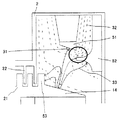
図2は本発明の実施形態1のX線管装置における反跳電子の軌道の一例を説明するための図であり、特に、陰極11から照射され回転陽極ターゲット14の表面で反跳された後に他の構造部材で吸収され消滅する場合の反跳電子の軌道を示すものである。また、図2においては、陰極11から出射される電子(熱電子)の一例として1つの電子31を示したが、実際の電子ビームの照射では多数の電子が陰極11から回転陽極ターゲット14に出射される。
<Step structure>
FIG. 2 is a view for explaining an example of the recoil electron trajectory in the X-ray tube apparatus according to the first embodiment of the present invention, in particular, after being irradiated from the
図2から明らかなように、陰極11から出射した電子(熱電子)31は、図2中に点線で示す等電位線32に直交するようにして、ほぼ直線的な矢印35で示す軌道で回転陽極ターゲット14に衝突する。この電子ビームの衝突により、回転陽極ターゲット14ではX線焦点からX線が発生しX線ビームとして、照射されることとなる。このとき、回転陽極ターゲット14には大量の電子ビームが照射されることとなるので、高温の状態となる。
As is apparent from FIG. 2, the electrons (thermoelectrons) 31 emitted from the
一方、回転陽極ターゲット14に照射された電子ビームの内、約50%程度がその表面で反跳し、反跳電子として、例えば矢印33に示す軌道で他の構造部材に衝突することとなる。このとき、実施形態1の回転陽極ターゲット14では、電子ビーム衝突面とフィン構造体21との間に反跳電子を捕捉するための段差23が形成される構成となっているので、回転陽極ターゲット14の表面で反跳された反跳電子の内の約10〜20%程度が段差23で吸収され、熱に変換されることとなる。その結果、反跳電子が再び回転陽極ターゲット14の電子ビーム衝突面に入射することによって発生されるX線(不要X線)の発生を抑えることが可能となる。
On the other hand, about 50% of the electron beam irradiated to the
ただし、段差23の形状として、放電への影響を考慮しエッジが立たないような形状とする。さらには、段差23を形成する面は、回転陽極ターゲット14の傾斜面及び平面部分どちらの場合であってもよく、反跳電子捕捉構造体12の影に隠れるように配置する。このように配置することで、陰極11と回転陽極ターゲット14との焦点面外での放電を抑制させることができる。すなわち、段差23と陰極11とを直線で結んだ場合、その直線上に反跳電子捕捉構造体12が配置されるように、当該段差23を形成している。
However, the shape of the
また、実施形態1のX線管装置では、回転陽極ターゲット14及び真空外囲器2は、フィン構造体21、22をそれぞれ備える構成となっているので、X線焦点での発熱及び段差23での発熱はフィン構造体21からフィン構造体22へ効率よく熱放射されると共に、フィン構造体22に放射された熱は真空外囲器2の壁面から冷媒に伝達される。すなわち、回転陽極ターゲット14のX線焦点で発生した熱は、X線焦点位置から直接熱放射されると共に、熱伝導によって当該回転陽極ターゲット14の全体、及び回転陽極ターゲット14に連結される回転陽極支持構造体15と回転支持機構16等へも伝熱され、各部位から熱放射される。
In the X-ray tube apparatus according to the first embodiment, the
また、回転陽極ターゲット14の回転中心軸部分に形成されるフィン構造体21にもX線焦点で発生した熱が熱伝導により伝熱されることとなる。このとき、フィン構造体21は複数個の円筒を列設した構成となっているので、その表面積が大きなものとなり、フィン構造体21からの放射熱は大きなものとなる。また、当該フィン構造体21に対向配置されるフィン構造体22も複数個の円筒を列設した構成となっているので、その表面積は大きなものとなる。従って、フィン構造体21からフィン構造体22を介して、回転陽極ターゲット14のX線焦点で発生した熱を真空外囲器2の側壁部から冷媒へ効率よく伝熱することが可能となるので、反跳電子の捕捉に伴う回転陽極ターゲット14の温度上昇を大幅に抑制することが可能となる。
Further, the heat generated at the X-ray focal point is also transferred to the
さらには、図2中の矢印では示していない反跳電子の内で、点線で示す等電位線32に従って回転陽極ターゲット14の回転中心軸方向に向かう反跳電子については、フィン構造体21又はフィン構造体22が備える円筒形状のフィンの内の何れかに衝突することとなる。その結果、実施形態1のX線管装置では、反跳電子が回転陽極ターゲット14の回転中心軸の近傍を直接に加熱することを防止できる。従って、実施形態1のX線管装置では、回転支持機構16が直接に加熱されることによる回転支持機構16を構成する図示しない軸受の加熱も抑制することができるという格別の効果を得ることが可能となる。特に、回転支持機構16を構成する図示しない軸受には、ボールベアリングのような転がり軸受や、回転軸面に溝を形成し液体金属潤滑剤を軸受隙間に満した動圧式すべり軸受などが使用されているので、軸受部分にかかる熱負担を軽減する効果は大きい。
Further, among the recoil electrons not shown by the arrows in FIG. 2, the recoil electrons directed toward the rotation center axis of the
以上説明したように、実施形態1のX線管装置では、回転陽極ターゲット14にフィン構造体21を形成すると共に、当該回転陽極ターゲット14の電子ビーム衝突位置よりもフィン構造体21に近い領域に、反跳電子を捕捉するための段差23を形成する構成となっている。このような構造とすることにより、反跳電子を効率よく捕捉すると共に、反跳電子の捕捉に伴う回転陽極ターゲット14の温度上昇を効率よく抑制することが可能となる。さらには、実施形態1のX線管装置では、回転陽極ターゲット14の電子ビーム衝突面と対向する真空外囲器2の内壁面に、フィン構造体22が形成される構成となっているので、回転陽極ターゲット14に形成したフィン構造体21からの輻射熱を効率よく真空外囲器2に伝熱させることが可能となる。その結果、回転陽極ターゲット14を効率よく冷却することが可能となる。すなわち当該回転陽極ターゲット14の温度上昇を抑制することが可能となるので、回転陽極ターゲット14の連結される回転陽極支持構造体15及び回転支持機構16の温度上昇も抑制することが可能となる。
As described above, in the X-ray tube apparatus according to the first embodiment, the
実施形態1のX線管装置では、真空外囲器2の内部である真空領域内に、回転陽極ターゲット14の熱を伝えるための熱交換手段となるフィン構造体21とフィン構造体22とを形成することにより、真空内における熱交換効率を向上させる構成となっている。
In the X-ray tube apparatus according to the first embodiment, the
なお、実施形態1のX線管装置では、回転陽極ターゲット14と真空外囲器2とにフィン構造体21、22を設ける構成としたが、これに限定されることはなく、何れか一方のフィン構造体を設ける構成でもよい。例えば、回転陽極ターゲット14の電子ビーム照射面側にのみフィン構造体21を設けた場合であっても、反跳電子捕捉構造体12や段差23等で捕捉出来なかった反跳電子が回転陽極ターゲット14の回転中心軸付近に到達することを当該フィン構造体21で大幅に低減させることが可能となるからである。さらには、当該フィン構造体21を設けることにより、回転陽極ターゲット14の表面積を大幅に増加させることが出来るので、輻射熱を効率よく放射することが可能となり、放熱性能が向上するからである。また、このときのフィン構造体21の形状は、対向面が真空外囲器2の内壁面となるので、同心円状の円筒形状に限定されることはなく、任意の凹凸形状とすることができる。
In the X-ray tube apparatus of the first embodiment, the
一方、真空外囲器2の内壁面側にのみフィン構造体22を設けた場合であっても、反跳電子捕捉構造体12や段差23等で捕捉出来なかった反跳電子が回転陽極ターゲット14の回転中心軸付近に到達することを、当該フィン構造体22で大幅に低減させることが可能となるからである。さらには、当該フィン構造体22を設けることにより、真空外囲器2の内壁面の面積を大幅に増加させることが出来るので、回転陽極ターゲット14から放出される輻射熱を効率よく吸収することが出来るので、回転陽極ターゲット14の温度上昇も抑制することが可能となるからである。この場合においても、対向面が円盤状の回転陽極ターゲット14となるので、フィン構造体22の形状は任意の凹凸形状でよい。
On the other hand, even when the
また、実施形態1のX線管装置では、回転陽極ターゲット14の電子ビーム照射面側に段差23を設け、該段差23で効率よく反跳電子を捕捉する構成としたが、これに限定されることはない。例えば、図8に示すように、実施形態1の回転陽極ターゲット14に形成した段差23のみを除いた構成であっても、フィン構造体21、22により回転中心軸近傍での反跳電子の捕捉に伴う回転陽極支持構造体15の加熱を抑制でき、フィン構造体21からフィン構造体22への熱交換を効率よく行うことが可能となるので、回転陽極ターゲット14及び回転陽極支持構造体15の温度上昇を抑制することができる。
In the X-ray tube apparatus according to the first embodiment, the
さらには、実施形態1のX線管装置では、フィン構造体21を形成するフィン厚さよりもフィン構造体22を形成するフィン厚さの方が薄い場合について説明したが、これに限定されることはなく、フィン構造体22を形成するフィン厚さの方が厚くてもよい。ただし、各フィンの厚さは冷却効率が高い形状が好ましいので、いわゆるフィン効率(=[実際に伝達される熱量]/[フィンの全表面積がフィンの基底温度に等しいと仮定した時に伝達される熱量])の高い形状が望ましい。このような形状は、フィンへの熱伝導及びフィンからの熱の輻射等を考慮したフィンの設計により実現可能である。
Furthermore, in the X-ray tube apparatus according to the first embodiment, the case where the fin thickness forming the
〈実施形態2〉
図3は本発明の実施形態2のX線管装置の概略構成を説明するための断面図であり、以下、図3に基づいて、実施形態2のX線管装置の全体構成を説明する。ただし、実施形態2のX線管装置では、回転陽極ターゲット14に形成されるフィン構造体21の形成方法及び段差を設けない構成が異なるのみで、他の構成は実施形態1のX線管装置と同様の構成となる。従って、以下の説明では、フィン構造体21の構成について詳細に説明する。
<
FIG. 3 is a cross-sectional view for explaining a schematic configuration of an X-ray tube apparatus according to
図3に示すように、実施形態2のX線管装置では、回転陽極ターゲット14の回転中心軸を中心として形成される複数個の同心円形状の溝部を形成することにより、フィン構造体21を形成する構成となっている。すなわち、実施形態2のX線管装置では、フィン構造体22のフィン(凸部)とフィン構造体21の溝部(凹部)24との位置が一致し、該溝部24にフィン構造体22の凸部が入り込む構成としている。このような構成とすることにより、フィン構造体21に形成される隣接する溝部24の間に形成される領域(見かけ上のフィン構造体21のフィン(凸部))が、フィン構造体22を形成する隣接するフィンとの間に形成される領域(見かけ上のフィン構造体22の溝部(凹部))には入り込む構成となる。
As shown in FIG. 3, in the X-ray tube apparatus of the second embodiment, the
以上の構成により、フィン構造体21に形成される隣接する溝部24の間に形成される領域(見かけ上のフィン構造体21のフィン(凸部))の周側面と、フィン構造体22を形成するフィン周側面とが対向して配置されることとなる。従って、実施形態1と同様に、フィン構造体21からフィン構造体22への熱伝導を効率よく行うことが可能となる。
With the above configuration, the peripheral surface of the region (the apparent fin (convex portion) of the fin structure 21) formed between the
また、実施形態2のX線管装置にあっても、フィン構造体21とフィン構造体22とにより、回転陽極ターゲット14の電子ビーム衝突面側における回転中心軸近傍への反跳電子の衝突を防止することが可能となるので、実施形態1と同様に、回転陽極支持構造体15及び回転支持機構16の温度上昇を抑えることが可能となる。
Even in the X-ray tube apparatus of the second embodiment, the
さらには、実施形態2のX線管装置の方が実施形態1よりもフィン構造体22で反跳電子が捕獲されやすいので、冷却効率を向上できるという格別の効果を得られる。
Furthermore, since the X-ray tube apparatus of the second embodiment is more likely to capture recoil electrons by the
〈実施形態3〉
図4は本発明の実施形態3のX線管装置の概略構成を説明するための断面図であり、以下、図4に基づいて、実施形態3のX線管装置の全体構成を説明する。ただし、実施形態3のX線管装置では、回転陽極ターゲット14に形成されるフィン構造体21を形成するフィンの形状及び段差を設けない構成が異なるのみで、他の構成は実施形態1のX線管装置と同様の構成となる。従って、以下の説明では、フィン構造体21の構成について詳細に説明する。
<Embodiment 3>
FIG. 4 is a cross-sectional view for explaining a schematic configuration of an X-ray tube apparatus according to Embodiment 3 of the present invention. Hereinafter, an overall configuration of the X-ray tube apparatus according to Embodiment 3 will be described with reference to FIG. However, in the X-ray tube apparatus of the third embodiment, only the shape of the fins forming the
図4から明らかなように、実施形態3のX線管装置では、回転陽極ターゲット14が備えるフィン構造体21を形成するフィンの内で、最外周に形成されるフィンがフィン構造体22の側に突出されると共に、回転陽極ターゲット14の外周方向に突出される形状となる。すなわち、実施形態3のフィン構造体21では、最外周に配置されるフィンが回転陽極ターゲット14の回転軸方向と平行な突出部と、該突出部から連続して形成され回転陽極ターゲット14の回転軸方向と直交する円環部とから構成される。ただし、円環部は回転陽極ターゲット14の回転軸方向と直交する形状に限定されることはなく、その形成角度は任意に設定可能である。すなわち、最外周に配置されるフィンの形状を実施形態1のフィン形状よりも複雑な形状とするものである。
As is apparent from FIG. 4, in the X-ray tube apparatus according to the third embodiment, among the fins forming the
このようなフィン構造体21を設けることにより、前述する実施形態1のX線管装置における効果に加えて、最外周に配置したフィンによる反跳電子の捕捉効率を実施形態1のX線管装置よりも向上させることができるという格別の効果が得られる。その結果、実施形態1、2のX線管装置よりも二次・三次の反跳電子を低減でき、不要なX線の発生をさらに低減できる。
By providing such a
さらには、フィンの表面積を増加させると共に、その対向面方向を真空外囲器2の内壁面方向とする構成となっているので、放熱効果を向上させることが可能となる。その結果、実施形態1のX線管装置における効果に加えて、さらに放熱性能を向上させることが出来るという格別の効果が得られる。
Furthermore, since it is the structure which makes the surface area of a fin increase and makes the opposing surface direction into the inner wall surface direction of the
〈実施形態4〉
図5は本発明の実施形態4のX線管装置の概略構成を説明するための断面図であり、以下、図5に基づいて、実施形態4のX線管装置の全体構成を説明する。ただし、実施形態4のX線管装置では、図5中に明示する陰極51の構成及び該陰極51を覆う反跳電子捕捉構造体52の構成並びにフィン構造体21の構成が大きく異なるのみで、他の基本的な構成は実施形態2のX線管装置と同様の構成となる。従って、以下の説明では、陰極51の構成及び反跳電子捕捉構造体52の構成並びにフィン構造体21の構成について詳細に説明する。なお、実施形態4の陰極51及び反跳電子捕捉構造体52の構成は、他の実施形態にも適用可能である。
<Embodiment 4>
FIG. 5 is a cross-sectional view for explaining a schematic configuration of an X-ray tube apparatus according to Embodiment 4 of the present invention. Hereinafter, an overall configuration of the X-ray tube apparatus according to Embodiment 4 will be described with reference to FIG. However, in the X-ray tube apparatus of the fourth embodiment, only the configuration of the
図5から明らかなように、実施形態4のX線管装置では、回転陽極ターゲット14から照射されるX線ビームの照射側から遠い領域(図5中の右側領域)、すなわち回転陽極ターゲット14の回転中心軸から遠い領域のみに反跳電子捕捉構造体52を形成する構成となっている。このような構成とすることにより、実施形態4のX線管装置では、反跳電子捕捉構造体52の構成を簡易な構造とし、反跳電子捕捉構造体52の搭載スペースの減少に伴う小型化、及びX線管装置本体の軽量化を可能としている。
As apparent from FIG. 5, in the X-ray tube apparatus of the fourth embodiment, the region far from the irradiation side of the X-ray beam irradiated from the rotating anode target 14 (the right region in FIG. 5), that is, the rotating
また、実施形態4のX線管装置では、陰極51の形状が回転陽極ターゲット14の回転中心軸方向に傾斜された構成となっている。この構成により、後に詳述するように、陰極51、反跳電子捕捉構造体52、及び回転陽極ターゲット14との間に生じる電界の分布を変化させると共に、陰極51から照射される電子ビームが反跳電子捕捉構造体52に捕捉されることを防止する構成としている。さらには、フィン構造体21を形成する複数のフィンの内で、最外周に形成されるフィン53の形状においても、その突出量及び形状が電界分布に大きな影響を与えることとなるので、実施形態4のフィン構造体21においては、後に詳述する構成とすることにより、電界分布を最適な状態に保持する構成としている。
In the X-ray tube apparatus of the fourth embodiment, the shape of the
このように、実施形態4のX線管装置においても、回転陽極ターゲット14の電子ビーム衝突面側にフィン構造体21が形成されると共に、該フィン構造体21に対向する真空外囲器2の内壁面にフィン構造体22を形成する構成となっているので、前述する実施形態1のX線管装置の効果を得ることが可能である。
As described above, also in the X-ray tube apparatus of the fourth embodiment, the
次に、図6に本発明の実施形態4のX線管装置における陰極及び反跳電子捕捉構造体並びに回転陽極ターゲット間における電位分布及び反跳電子の軌道の一例を説明するための図を示し、以下、図6に基づいて、反跳電子の低減効果を説明する。図6においても、前述する図2と同様に、陰極11から出射される電子(熱電子)の一例として1つの電子31を示したが、実際の電子ビームの照射では多数の電子が陰極11から回転陽極ターゲット14に出射される。
Next, FIG. 6 is a diagram for explaining an example of the potential distribution and recoil electron trajectory between the cathode and recoil electron capturing structure and the rotating anode target in the X-ray tube apparatus according to Embodiment 4 of the present invention. Hereinafter, the effect of reducing recoil electrons will be described with reference to FIG. 6 also shows one
実施形態4のX線管装置では、反跳電子捕捉構造体52をX線ビームの照射側にのみ設ける構成となっている。この場合、反跳電子捕捉構造体52が形成される側と形成されない側とでは、陰極51の周辺の電界分布が大きく異なることとなる。すなわち、図6の丸枠で囲む領域に示すように、反跳電子捕捉構造体52が形成される側では、陰極52と反跳電子捕捉構造体52との間の電界が大きくなる。この電界により、実施形態4の反跳電子捕捉構造体52と陰極51との間に反跳電子を集まりやすくし、該反跳電子捕捉構造体52で効率よく反跳電子を捕捉する。
In the X-ray tube apparatus of the fourth embodiment, the recoil
さらには、実施形態4の反跳電子捕捉構造体52では、回転陽極ターゲット14の側の面を曲面形状とすることにより、該曲面に沿った等電位線32で示す電界分布を形成している。この構成により、反跳電子捕捉構造体52に衝突した反跳電子の内で、再度反跳してしまう反跳電子を大幅に低減させている。
Furthermore, in the recoil
このとき、実施形態4の陰極51では、その頭頂部の形状が反跳電子捕捉構造体52に近い側と遠い側とで異なる形状とする。すなわち、反跳電子捕捉構造体52に近い側から遠い側に向かって陰極51の頭頂部に傾斜を形成することにより、当該陰極51から放射される電子の放出角度を変化させ、陰極51から照射される電子ビームが反跳電子捕捉構造体52に捕捉されることを防止する構成としている。
At this time, in the
さらには、実施形態4のX線管装置では、反跳電子捕捉構造体52が形成されない側に反跳する反跳電子を効率よく捕捉するために、フィン構造体21の最外周に形成されるフィン53を用いる構成としている。
Furthermore, in the X-ray tube device of Embodiment 4, the X-ray tube device is formed on the outermost periphery of the
このように、実施形態4のX線管装置では、陰極51、反跳電子捕捉構造体52、回転陽極ターゲット14、及びフィン構造体21がそれぞれ供働して所望の電界分布を得る構成となっている。すなわち、実施形態4のX線管装置では、構造物である反跳電子捕捉構造体52による反跳電子の捕捉と、構造物であるフィン構造体21及びフィン構造体22とによる反跳電子の直接的な遮蔽のみならず、回転陽極ターゲット14の電子ビーム衝突面、またその近傍、さらには陰極51の近傍に凹凸や適切な形状を設けることで、反跳電子の捕捉に適した電界分布を形成し、反跳電子を回転陽極軸中心方向へ飛散させない構成としている。
As described above, in the X-ray tube apparatus according to the fourth embodiment, the
さらには、各構造体の形状を変化させることにより、電界分布を形成することで反跳電子を所望の方向に導くことも可能である。このような電界分布の形成は反跳電子捕捉構造体(コレクタ)52の形状、回転陽極ターゲット14の電子衝突面側の形状、またそれに対向する面の形状、さらには陰極51の形状、電子放出する角度、図示しない集束体の形状を組み合わせることで可能となる。
Furthermore, recoil electrons can be guided in a desired direction by changing the shape of each structure to form an electric field distribution. Such an electric field distribution is formed by the shape of the recoil electron capturing structure (collector) 52, the shape of the
このように本願発明を適用することにより、従来では円筒形状とする必要があった反跳電子捕捉構造体(コレクタ)52が、半円筒など、焦点面を基準に見て陽極回転ターゲットの中心方向とは反対方向、つまりX線管1の外側のみの構造で済むことになる。この構造により、反跳電子捕捉構造体52は管容器18に近い部分にのみ形成されるので、反跳電子捕捉構造体52の冷却が容易になるという格別の効果を得ることが可能となる。
In this way, by applying the present invention, the recoil electron capturing structure (collector) 52 that has conventionally been required to have a cylindrical shape, such as a semi-cylinder, is centered on the anode rotation target with reference to the focal plane. Only the opposite direction, that is, the structure outside the
〈実施形態5〉
図7は本発明の実施形態5のX線管装置の概略構成を説明するための断面図であり、以下、図7に基づいて、実施形態5のX線管装置の全体構成を説明する。ただし、実施形態5のX線管装置では、回転陽極ターゲット14を支持する両持軸受を構成する回転支持機構16、71、フィン構造体21、22、及び回転陽極支持構造体15の構成を除く、他の構成は実施形態4のX線管装置と同様の構成となる。従って、以下の説明では、回転陽極ターゲット14を支持する両持軸受を構成する回転支持機構16、71、フィン構造体21、22、及び回転陽極支持構造体15の構成について詳細に説明する。なお、実施形態5の回転支持機構16、71、フィン構造体21、22、及び回転陽極支持構造体15の構成は、他の実施形態1〜3にも適用可能である。
<Embodiment 5>
FIG. 7 is a cross-sectional view for explaining a schematic configuration of an X-ray tube apparatus according to Embodiment 5 of the present invention. Hereinafter, an overall configuration of the X-ray tube apparatus according to Embodiment 5 will be described with reference to FIG. However, in the X-ray tube apparatus according to the fifth embodiment, the configurations of the
図7から明らかなように、実施形態5のX線管装置は、回転陽極ターゲット14を貫通する回転陽極支持構造体15を備える構成となっており、該回転陽極支持構造体15の一端に図示しないロータを備える回転支持機構16が配置され、他端に回転支持機構71が配置される構成となっている。すなわち、実施形態5のX線管装置では、回転陽極ターゲット14を介して、一端側に回転支持機構16が配置され、他端側に回転支持機構71が配置されるいわゆる両持軸受の構成となっている。なお、回転支持機構16、71の方式は、周知の転がり軸受け方式や流体軸受等のすべり軸受のいずれであってもよい。また、実施形態5のX線管装置においても、回転陽極ターゲット14の裏面側に回転支持機構15が配置され、回転陽極ターゲット14の電子ビーム照射面側に回転支持機構15が配置される構成となっている。
As is clear from FIG. 7, the X-ray tube apparatus according to the fifth embodiment includes a rotating
また、実施形態5では、回転陽極ターゲット14を貫通して回転陽極支持構造体15が配置される構成となっているので、実施形態5のフィン構造体21、22においても、当該回転陽極支持構造体15が配置される領域を避けた領域である回転陽極支持構造体15の外周領域に、フィン構造体21、22を形成する複数のフィンが配置される構成となっている。
In the fifth embodiment, since the rotary
従って、従来の構成では、回転陽極支持構造体15に直接反跳電子が到達し、当該回転陽極支持構造体15を直接加熱する構成であったが、実施形態5のX線管装置では、回転陽極支持構造体15の外周部分に形成されるフィン構造体21、22が回転陽極支持構造体15への反跳電子の到達を阻止する構成となっている。その結果、反跳電子が直接的に回転陽極支持構造体15に捕捉され、当該回転陽極支持構造体15を加熱してしまうことを防止することが出来るので、前述する実施形態1の効果に加えて、回転陽極支持構造体15の温度上昇をさらに抑制できるという格別の効果を得ることができる。
Therefore, in the conventional configuration, recoil electrons directly reach the rotating
〈実施形態6〉
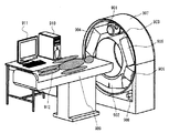
図9は本発明の実施形態6のX線CT装置の概略構成を説明するための図である。図9に示すX線CT装置は、X線管装置901を除く他の構成は従来のX線CT装置と同様の構成となる。なお、本発明のX線管装置の適用範囲はX線CT装置に限定されることはなく、他のX線撮影装置にも適用可能である。
<Embodiment 6>
FIG. 9 is a diagram for explaining a schematic configuration of an X-ray CT apparatus according to Embodiment 6 of the present invention. The X-ray CT apparatus shown in FIG. 9 has the same configuration as the conventional X-ray CT apparatus except for the
図9から明らかなように、実施形態6のX線CT装置はX線ビームを発生する実施形態1〜5の何れかのX線管装置901と、該X線管装置901に対向配置されるX線検出器902とで撮影系が形成される。該撮影系は回転体903に収納され、該回転体903と共に高速回転される。また、回転体903には電源904、905と、錘906も収納される構成となっている。該回転体903は床面に立設される筐体907に回転可能に取り付けられ、モータ908により高速回転され、架台909に搭載される被検者912の周囲360度からの回転撮影を可能としている。
As is apparent from FIG. 9, the X-ray CT apparatus according to the sixth embodiment is disposed opposite to the
被検者912の周囲360度から撮影されたX線像は画像処理装置910で周知の再構成演算等が行われて被検者912の断層像や3次元像等が生成され、モニタ911に表示される。
An X-ray image taken from 360 degrees around the subject 912 is subjected to a known reconstruction calculation or the like by the
このとき、実施形態6のX線CT装置では、本願発明の実施形態1〜5のX線管装置を用いる構成となっているので、多量のX線ビームを長時間出力することができる。その結果、被検者912のスキャン(CT撮影)に要する時間を短縮することが可能となり、心臓等の比較的動きの速い臓器であってもモーションアーチファクトを抑えた再構成画像を得ることができる。 At this time, since the X-ray CT apparatus of the sixth embodiment is configured to use the X-ray tube apparatus of the first to fifth embodiments of the present invention, a large amount of X-ray beams can be output for a long time. As a result, the time required for scanning (CT imaging) of the subject 912 can be shortened, and a reconstructed image with reduced motion artifacts can be obtained even for a relatively fast organ such as the heart. .
また、被検者912のスキャン(CT撮影)に要する時間を短縮することが可能となるので、被検者912の負担を低減できると共に、より多くの被検者のX線CT撮影を行うことができる。 In addition, since the time required for scanning (CT imaging) of the subject 912 can be shortened, the burden on the subject 912 can be reduced, and X-ray CT imaging of more subjects can be performed. Can do.
また、実施形態4、5のX線管装置を用いることにより、X線管装置901の重量を軽量化でき回転体903にかかる負荷を低減できるので、さらに高速に回転体903(撮影系)を回転させることが可能となり、さらなる撮影時間の短縮が可能となる。
Further, by using the X-ray tube apparatus of Embodiments 4 and 5, the weight of the
さらには、実施形態1〜5のX線管装置を用いるので、X線CT装置本体の機械的な信頼性も向上させることができる。
Furthermore, since the X-ray tube apparatus of
なお、本発明の実施形態1〜5のX線管装置では、真空外囲器2の内壁面に配置したフィン構造体22が、回転陽極ターゲット14に配置されるフィン構造体21よりも電子ビーム衝突面に近い構成としているが、これに限定されることはない。例えば、真空外囲器2の内壁面に配置したフィン構造体22を形成するフィン(凸部)を最外周側に配置することにより、反跳電子のフィン構造体22への到達割合を大きくすることが可能となるので、反跳電子による回転陽極ターゲット14の温度上昇を抑えることが可能となると共に、X線管装置全体の放熱性能を向上させることができるという格別の効果を得ることが可能となる。
In the X-ray tube apparatus according to the first to fifth embodiments of the present invention, the
本発明の実施形態1〜5のX線管装置では、フィン構造体22の凸部形状のフィンに対応した円筒状の凹凸形状である段差を設けフィン構造体21を形成する構成としたが、これに限定されることはない。例えば、フィン構造体21の一部に切り欠き部として、フィンの頭頂部から底部に及ぶ欠損領域を形成することにより、フィン構造体21の重量を低減することが可能となる。
In the X-ray tube apparatus according to the first to fifth embodiments of the present invention, the
さらには、本発明の実施形態1〜5のX線管装置では、フィン構造体21及びフィン構造体22を形成するフィンの数を複数個形成する場合について説明したが、各フィン構造体におけるフィンは1以上であればよい。
Furthermore, in the X-ray tube apparatus according to the first to fifth embodiments of the present invention, the case where a plurality of fins forming the
さらには、本発明の実施形態1〜5のX線管装置では、回転陽極ターゲット14の中心軸の近傍に設ける凹凸部、及び真空外囲器2の対向壁面に設ける凹凸部として、角部を有するフィン構造体21及びフィン構造体22を設ける構成としたが、前述する形状に限定されることはなく、凹部及び凸部に曲面状に形成した緩やかな凹凸形状であってもよい。
Furthermore, in the X-ray tube apparatus according to the first to fifth embodiments of the present invention, corner portions are provided as the uneven portions provided in the vicinity of the central axis of the
以上、本発明者によってなされた発明を、前記発明の実施形態に基づき具体的に説明したが、本発明は、前記発明の実施形態に限定されるものではなく、その要旨を逸脱しない範囲において種々変更可能である。 As mentioned above, the invention made by the present inventor has been specifically described based on the embodiment of the invention. However, the invention is not limited to the embodiment of the invention, and various modifications can be made without departing from the scope of the invention. It can be changed.
1……X線管装置、2……真空外囲器、11、51……陰極
12、52……反跳電子捕捉構造体(コレクタ)、13……放射窓
14……回転陽極ターゲット、15……回転陽極支持構造体
16、71……回転支持機構、17……ステータ、21、22……フィン構造体
23……段差、24……溝部、31……電子、32……等電位線
33、34……矢印(反跳電子軌道)、35……矢印(電子ビーム軌道)
53……最外周のフィン、901……X線管装置、902……X線検出器
903……回転体、904、905……電源、906……錘、907……筐体
908……モータ、909……架台、910……画像処理装置、911……モニタ
912……被検者
DESCRIPTION OF
53 ... Fins on the outermost periphery, 901 ... X-ray tube device, 902 ...
Claims (5)
前記外囲器の内壁面側に形成され、前記陽極ターゲットの電子ビーム衝突面側に突出する第1の凹凸部を備えることを特徴とするX線管装置。 A cathode that emits an electron beam; an anode target that collides the electron beam and generates X-rays with the collided position as a focal position; a rotating mechanism that rotates the anode target; the cathode and the anode target An X-ray tube device comprising an envelope that holds the vacuum in a vacuum,
An X-ray tube apparatus comprising: a first uneven portion formed on an inner wall surface side of the envelope and protruding toward an electron beam collision surface side of the anode target.
前記陽極ターゲットの電子ビーム衝突面側の領域であり、少なくとも電子ビーム衝突領域を除く領域に形成され、前記外囲器の内壁面側に突出する第2の凹凸部をさらに備え、
前記第1の凹凸部と前記第2の凹凸部との凹凸が相互に組み合わされて配置されることを特徴とするX線管装置。 The X-ray tube apparatus according to claim 1,
A region on the electron beam collision surface side of the anode target, further comprising a second concavo-convex portion that is formed in a region excluding at least the electron beam collision region and protrudes toward the inner wall surface side of the envelope ;
The X-ray tube apparatus characterized in that the first uneven portion and the second uneven portion are arranged in combination with each other.
前記第2の凹凸部と前記電子ビーム衝突領域との間に段差を備えることを特徴とするX線管装置。 The X-ray tube apparatus according to claim 2,
An X-ray tube apparatus comprising a step between the second uneven portion and the electron beam collision region.
前記X線管装置に対向配置され前記被検体を透過したX線を検出するX線検出器と、
前記X線管装置と前記X線検出器を搭載し前記被検体の周囲を回転するスキャナと、
前記X線検出器で検出した投影データを前記2つの焦点位置毎に収集するデータ収集部と、
前記データ収集部で収集した投影データに基づき前記被検体の断層像を再構成する画像再構成装置と、
前記画像再構成装置で再構成した断層像を表示する画像表示装置とを備えたことを特徴とするX線CT装置。 The X-ray tube apparatus according to any one of claims 1 to 4, which irradiates a subject with X-rays;
An X-ray detector that is disposed opposite to the X-ray tube device and detects X-rays transmitted through the subject;
A scanner mounted with the X-ray tube device and the X-ray detector and rotating around the subject;
A data collection unit for collecting projection data detected by the X-ray detector for each of the two focal positions;
An image reconstruction device for reconstructing a tomographic image of the subject based on the projection data collected by the data collection unit;
An X-ray CT apparatus comprising: an image display device that displays a tomographic image reconstructed by the image reconstruction device.
Priority Applications (1)
| Application Number | Priority Date | Filing Date | Title |
|---|---|---|---|
| JP2010000393A JP5468911B2 (en) | 2010-01-05 | 2010-01-05 | X-ray tube apparatus and X-ray CT apparatus using the same |
Applications Claiming Priority (1)
| Application Number | Priority Date | Filing Date | Title |
|---|---|---|---|
| JP2010000393A JP5468911B2 (en) | 2010-01-05 | 2010-01-05 | X-ray tube apparatus and X-ray CT apparatus using the same |
Publications (3)
| Publication Number | Publication Date |
|---|---|
| JP2011141956A JP2011141956A (en) | 2011-07-21 |
| JP2011141956A5 JP2011141956A5 (en) | 2013-02-14 |
| JP5468911B2 true JP5468911B2 (en) | 2014-04-09 |
Family
ID=44457677
Family Applications (1)
| Application Number | Title | Priority Date | Filing Date |
|---|---|---|---|
| JP2010000393A Active JP5468911B2 (en) | 2010-01-05 | 2010-01-05 | X-ray tube apparatus and X-ray CT apparatus using the same |
Country Status (1)
| Country | Link |
|---|---|
| JP (1) | JP5468911B2 (en) |
Families Citing this family (2)
| Publication number | Priority date | Publication date | Assignee | Title |
|---|---|---|---|---|
| EP2839499B1 (en) | 2012-06-14 | 2017-03-22 | Siemens Aktiengesellschaft | Spark gap |
| WO2014125702A1 (en) | 2013-02-18 | 2014-08-21 | 株式会社島津製作所 | Rotating envelope x-ray tube device |
Family Cites Families (3)
| Publication number | Priority date | Publication date | Assignee | Title |
|---|---|---|---|---|
| US4943989A (en) * | 1988-08-02 | 1990-07-24 | General Electric Company | X-ray tube with liquid cooled heat receptor |
| US7359486B2 (en) * | 2005-12-20 | 2008-04-15 | General Electric Co. | Structure for collecting scattered electrons |
| US20090154649A1 (en) * | 2006-05-22 | 2009-06-18 | Koninklijke Philips Electronics N.V. | X-ray tube whose electron beam is manipulated synchronously with the rotational anode movement |
-
2010
- 2010-01-05 JP JP2010000393A patent/JP5468911B2/en active Active
Also Published As
| Publication number | Publication date |
|---|---|
| JP2011141956A (en) | 2011-07-21 |
Similar Documents
| Publication | Publication Date | Title |
|---|---|---|
| JP5265906B2 (en) | Convection cooled X-ray tube target and manufacturing method thereof | |
| US20110051895A1 (en) | X-ray system with efficient anode heat dissipation | |
| JP5809806B2 (en) | X-ray device with wide coverage | |
| US7359486B2 (en) | Structure for collecting scattered electrons | |
| EP0917176A2 (en) | Straddle bearing assembly for a rotating anode X-ray tube | |
| JPH0888093A (en) | X-ray tube assembly | |
| US8259905B2 (en) | X-ray tube having a rotating and linearly translating anode | |
| JP2004513688A (en) | Integration of cooling jacket and flow baffle into X-ray tube metal frame insert | |
| US7643614B2 (en) | Method and apparatus for increasing heat radiation from an x-ray tube target shaft | |
| US20060034425A1 (en) | Cantilever and straddle x-ray tube configurations for a rotating anode with vacuum transition chambers | |
| JP5468911B2 (en) | X-ray tube apparatus and X-ray CT apparatus using the same | |
| JP2005168712A (en) | X-ray ct apparatus | |
| US20050226386A1 (en) | Electron collector system | |
| JP5890309B2 (en) | X-ray tube apparatus and X-ray CT apparatus | |
| US6603834B1 (en) | X-ray tube anode cold plate | |
| US7852987B2 (en) | X-ray tube having a rotating and linearly translating anode | |
| US10376229B2 (en) | Computed tomographic mammography system | |
| JP5893927B2 (en) | X-ray tube apparatus and X-ray CT apparatus | |
| JP2011504647A (en) | X-ray tube having a focal position close to the tube end | |
| JP5959866B2 (en) | X-ray tube apparatus and X-ray CT apparatus | |
| JP5268406B2 (en) | X-ray CT scanner and X-ray tube apparatus | |
| JP6798941B2 (en) | X-ray tube device and X-ray CT device | |
| US20240105415A1 (en) | X-ray tube assembly and x-ray ct equipment | |
| JP5766128B2 (en) | X-ray tube apparatus and X-ray CT apparatus | |
| JP4665055B2 (en) | X-ray CT system |
Legal Events
| Date | Code | Title | Description |
|---|---|---|---|
| A521 | Request for written amendment filed |
Free format text: JAPANESE INTERMEDIATE CODE: A523 Effective date: 20121219 |
|
| A621 | Written request for application examination |
Free format text: JAPANESE INTERMEDIATE CODE: A621 Effective date: 20121219 |
|
| A977 | Report on retrieval |
Free format text: JAPANESE INTERMEDIATE CODE: A971007 Effective date: 20130904 |
|
| A131 | Notification of reasons for refusal |
Free format text: JAPANESE INTERMEDIATE CODE: A131 Effective date: 20130910 |
|
| A521 | Request for written amendment filed |
Free format text: JAPANESE INTERMEDIATE CODE: A523 Effective date: 20131031 |
|
| TRDD | Decision of grant or rejection written | ||
| A01 | Written decision to grant a patent or to grant a registration (utility model) |
Free format text: JAPANESE INTERMEDIATE CODE: A01 Effective date: 20140114 |
|
| A61 | First payment of annual fees (during grant procedure) |
Free format text: JAPANESE INTERMEDIATE CODE: A61 Effective date: 20140130 |
|
| R150 | Certificate of patent or registration of utility model |
Ref document number: 5468911 Country of ref document: JP Free format text: JAPANESE INTERMEDIATE CODE: R150 Free format text: JAPANESE INTERMEDIATE CODE: R150 |
|
| S111 | Request for change of ownership or part of ownership |
Free format text: JAPANESE INTERMEDIATE CODE: R313111 |
|
| S533 | Written request for registration of change of name |
Free format text: JAPANESE INTERMEDIATE CODE: R313533 |
|
| R350 | Written notification of registration of transfer |
Free format text: JAPANESE INTERMEDIATE CODE: R350 |
|
| S111 | Request for change of ownership or part of ownership |
Free format text: JAPANESE INTERMEDIATE CODE: R313111 |
|
| R350 | Written notification of registration of transfer |
Free format text: JAPANESE INTERMEDIATE CODE: R350 |
|
| R250 | Receipt of annual fees |
Free format text: JAPANESE INTERMEDIATE CODE: R250 |
|
| R250 | Receipt of annual fees |
Free format text: JAPANESE INTERMEDIATE CODE: R250 |
|
| R250 | Receipt of annual fees |
Free format text: JAPANESE INTERMEDIATE CODE: R250 |