EP4421584A1 - Rollbare elektronische vorrichtung mit schaltabschnitt - Google Patents
Rollbare elektronische vorrichtung mit schaltabschnitt Download PDFInfo
- Publication number
- EP4421584A1 EP4421584A1 EP22895886.4A EP22895886A EP4421584A1 EP 4421584 A1 EP4421584 A1 EP 4421584A1 EP 22895886 A EP22895886 A EP 22895886A EP 4421584 A1 EP4421584 A1 EP 4421584A1
- Authority
- EP
- European Patent Office
- Prior art keywords
- gear
- housing
- electronic device
- switching unit
- state
- Prior art date
- Legal status (The legal status is an assumption and is not a legal conclusion. Google has not performed a legal analysis and makes no representation as to the accuracy of the status listed.)
- Granted
Links
Images


Classifications
-
- G—PHYSICS
- G06—COMPUTING OR CALCULATING; COUNTING
- G06F—ELECTRIC DIGITAL DATA PROCESSING
- G06F1/00—Details not covered by groups G06F3/00 - G06F13/00 and G06F21/00
- G06F1/16—Constructional details or arrangements
- G06F1/1613—Constructional details or arrangements for portable computers
- G06F1/1615—Constructional details or arrangements for portable computers with several enclosures having relative motions, each enclosure supporting at least one I/O or computing function
- G06F1/1624—Constructional details or arrangements for portable computers with several enclosures having relative motions, each enclosure supporting at least one I/O or computing function with sliding enclosures, e.g. sliding keyboard or display
-
- G—PHYSICS
- G05—CONTROLLING; REGULATING
- G05B—CONTROL OR REGULATING SYSTEMS IN GENERAL; FUNCTIONAL ELEMENTS OF SUCH SYSTEMS; MONITORING OR TESTING ARRANGEMENTS FOR SUCH SYSTEMS OR ELEMENTS
- G05B19/00—Program-control systems
- G05B19/02—Program-control systems electric
- G05B19/04—Program control other than numerical control, i.e. in sequence controllers or logic controllers
-
- G—PHYSICS
- G06—COMPUTING OR CALCULATING; COUNTING
- G06F—ELECTRIC DIGITAL DATA PROCESSING
- G06F1/00—Details not covered by groups G06F3/00 - G06F13/00 and G06F21/00
- G06F1/16—Constructional details or arrangements
- G06F1/1613—Constructional details or arrangements for portable computers
- G06F1/1628—Enclosures for carrying portable computers with peripheral devices, e.g. cases for a laptop and a printer
-
- G—PHYSICS
- G06—COMPUTING OR CALCULATING; COUNTING
- G06F—ELECTRIC DIGITAL DATA PROCESSING
- G06F1/00—Details not covered by groups G06F3/00 - G06F13/00 and G06F21/00
- G06F1/16—Constructional details or arrangements
- G06F1/1613—Constructional details or arrangements for portable computers
- G06F1/1633—Constructional details or arrangements of portable computers not specific to the type of enclosures covered by groups G06F1/1615 - G06F1/1626
- G06F1/1637—Details related to the display arrangement, including those related to the mounting of the display in the housing
- G06F1/1652—Details related to the display arrangement, including those related to the mounting of the display in the housing the display being flexible, e.g. mimicking a sheet of paper, or rollable
-
- G—PHYSICS
- G06—COMPUTING OR CALCULATING; COUNTING
- G06F—ELECTRIC DIGITAL DATA PROCESSING
- G06F1/00—Details not covered by groups G06F3/00 - G06F13/00 and G06F21/00
- G06F1/16—Constructional details or arrangements
- G06F1/1613—Constructional details or arrangements for portable computers
- G06F1/1633—Constructional details or arrangements of portable computers not specific to the type of enclosures covered by groups G06F1/1615 - G06F1/1626
- G06F1/1675—Miscellaneous details related to the relative movement between the different enclosures or enclosure parts
- G06F1/1681—Details related solely to hinges
-
- G—PHYSICS
- G06—COMPUTING OR CALCULATING; COUNTING
- G06F—ELECTRIC DIGITAL DATA PROCESSING
- G06F1/00—Details not covered by groups G06F3/00 - G06F13/00 and G06F21/00
- G06F1/16—Constructional details or arrangements
- G06F1/1613—Constructional details or arrangements for portable computers
- G06F1/1633—Constructional details or arrangements of portable computers not specific to the type of enclosures covered by groups G06F1/1615 - G06F1/1626
- G06F1/1684—Constructional details or arrangements related to integrated I/O peripherals not covered by groups G06F1/1635 - G06F1/1675
-
- G—PHYSICS
- G06—COMPUTING OR CALCULATING; COUNTING
- G06F—ELECTRIC DIGITAL DATA PROCESSING
- G06F1/00—Details not covered by groups G06F3/00 - G06F13/00 and G06F21/00
- G06F1/16—Constructional details or arrangements
- G06F1/20—Cooling means
- G06F1/203—Cooling means for portable computers, e.g. for laptops
-
- G—PHYSICS
- G06—COMPUTING OR CALCULATING; COUNTING
- G06F—ELECTRIC DIGITAL DATA PROCESSING
- G06F1/00—Details not covered by groups G06F3/00 - G06F13/00 and G06F21/00
- G06F1/16—Constructional details or arrangements
- G06F1/20—Cooling means
- G06F1/206—Cooling means comprising thermal management
-
- G—PHYSICS
- G06—COMPUTING OR CALCULATING; COUNTING
- G06F—ELECTRIC DIGITAL DATA PROCESSING
- G06F1/00—Details not covered by groups G06F3/00 - G06F13/00 and G06F21/00
- G06F1/26—Power supply means, e.g. regulation thereof
- G06F1/32—Means for saving power
- G06F1/3203—Power management, i.e. event-based initiation of a power-saving mode
- G06F1/3206—Monitoring of events, devices or parameters that trigger a change in power modality
- G06F1/3212—Monitoring battery levels, e.g. power saving mode being initiated when battery voltage goes below a certain level
-
- H—ELECTRICITY
- H04—ELECTRIC COMMUNICATION TECHNIQUE
- H04M—TELEPHONIC COMMUNICATION
- H04M1/00—Substation equipment, e.g. for use by subscribers
- H04M1/02—Constructional features of telephone sets
- H04M1/0202—Portable telephone sets, e.g. cordless phones, mobile phones or bar type handsets
- H04M1/0206—Portable telephones comprising a plurality of mechanically joined movable body parts, e.g. hinged housings
- H04M1/0208—Portable telephones comprising a plurality of mechanically joined movable body parts, e.g. hinged housings characterized by the relative motions of the body parts
- H04M1/0235—Slidable or telescopic telephones, i.e. with a relative translation movement of the body parts; Telephones using a combination of translation and other relative motions of the body parts
- H04M1/0237—Sliding mechanism with one degree of freedom
-
- H—ELECTRICITY
- H04—ELECTRIC COMMUNICATION TECHNIQUE
- H04M—TELEPHONIC COMMUNICATION
- H04M1/00—Substation equipment, e.g. for use by subscribers
- H04M1/02—Constructional features of telephone sets
- H04M1/0202—Portable telephone sets, e.g. cordless phones, mobile phones or bar type handsets
- H04M1/026—Details of the structure or mounting of specific components
- H04M1/0266—Details of the structure or mounting of specific components for a display module assembly
- H04M1/0268—Details of the structure or mounting of specific components for a display module assembly including a flexible display panel
-
- H—ELECTRICITY
- H04—ELECTRIC COMMUNICATION TECHNIQUE
- H04M—TELEPHONIC COMMUNICATION
- H04M2250/00—Details of telephonic subscriber devices
- H04M2250/12—Details of telephonic subscriber devices including a sensor for measuring a physical value, e.g. temperature or motion
Definitions
- Various embodiments of the disclosure relate to a rollable electronic device including a switching unit.
- electronic devices may implement not only communication functions, but also entertainment functions such as games, multimedia functions such as music/video playback, communication and security functions for mobile banking, calendar management, and electronic wallet functions. These electronic devices are being miniaturized so that they may be conveniently carried by users.
- an electronic device includes a housing including a first housing and a second housing accommodating at least a portion of the first housing and guiding sliding of the first housing, a display configured to be at least partially foldable based on sliding of the first housing, a motor unit disposed within the housing, a power transmission unit disposed within the housing, and including a gear assembly configured to receive at least a portion of a driving force generated by the motor unit and a gear housing configured to rotate together with at least a portion of the gear assembly, a switching unit disposed within the housing and configured to control a rotation of the gear housing, a sensor module configured to detect at least one of an internal operation state of the electronic device, an external environmental state, or a user input provided to the electronic device, and a processor configured to adjust a connection state between the switching unit and the gear housing based on the state or input detected by the sensor module.
- an electronic device includes a housing including a first housing and a second housing accommodating at least a portion of the first housing and guiding sliding of the first housing, a display configured to be at least partially unfolded based on movement of the first housing, a motor unit disposed within the housing and configured to generate a first driving force for moving the display, a first shaft connected to the motor unit and configured to rotate around a first rotation axis, a first gear connected to the first shaft, a second shaft spaced apart from the first shaft and configured to rotate around the first rotation axis, a third gear connected to the second shaft, at least one second gear meshed with the first gear and the third gear, and a gear shaft connected to the at least one second gear to be rotatable around a second rotation axis perpendicular to the first rotation axis, a gear housing connected to the gear shaft, and a switching unit configured to contact the gear housing or to be spaced from the gear housing.
- a portion of the switching unit When the switching unit is in a first state, a portion
- an electronic device includes a housing, a motor unit connected to a first shaft, a second shaft spaced apart from the first shaft, a switching unit configured to control transmission of power generated by the motor unit from the first shaft to the second shaft by at least partially moving, a power transmission unit configured to transmit the power generated by the motor unit to the second shaft using the first shaft, based on the movement of the switching unit, a display configured to be unfolded based on movement of the housing configured to at least partially move based on rotation of the second shaft, when the power generated by the motor unit is transmitted to the second shaft through the power transmission unit, a sensor module configured to detect a user input provided to the electronic device, and a processor configured to control the switching unit based on the user input.
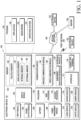
- FIG. 1 is a block diagram illustrating an electronic device in a network environment according to various embodiments.
- an electronic device 101 in a network environment 100 may communicate with an electronic device 102 via a first network 198 (e.g., a short-range wireless communication network), or an electronic device 104 or a server 108 via a second network 199 (e.g., a long-range wireless communication network).
- the electronic device 101 may communicate with the electronic device 104 via the server 108.
- the electronic device 101 may include a processor 120, memory 130, an input module 150, a sound output module 155, a display module 160, an audio module 170, a sensor module 176, an interface 177, a connecting terminal 178, a haptic module 179, a camera module 180, a power management module 188, a battery 189, a communication module 190, a subscriber identification module (SIM) 196, or an antenna module 197.
- at least one of the components e.g., the connecting terminal 178) may be omitted from the electronic device 101, or one or more other components may be added in the electronic device 101.
- some of the components e.g., the sensor module 176, the camera module 180, or the antenna module 197) may be implemented as a single component (e.g., the display module 160).
- the processor 120 may execute, for example, software (e.g., a program 140) to control at least one other component (e.g., a hardware or software component) of the electronic device 101 coupled with the processor 120, and may perform various data processing or computation.
- the processor 120 may store a command or data received from another component (e.g., the sensor module 176 or the communication module 190) in volatile memory 132, process the command or the data stored in the volatile memory 132, and store resulting data in non-volatile memory 134.
- the processor 120 may include a main processor 121 (e.g., a central processing unit (CPU) or an application processor (AP)), or an auxiliary processor 123 (e.g., a graphics processing unit (GPU), a neural processing unit (NPU), an image signal processor (ISP), a sensor hub processor, or a communication processor (CP)) that is operable independently from, or in conjunction with, the main processor 121.
- a main processor 121 e.g., a central processing unit (CPU) or an application processor (AP)
- auxiliary processor 123 e.g., a graphics processing unit (GPU), a neural processing unit (NPU), an image signal processor (ISP), a sensor hub processor, or a communication processor (CP)
- the main processor 121 may be adapted to consume less power than the main processor 121, or to be specific to a specified function.
- the auxiliary processor 123 may be implemented as separate from, or as part of the main processor 121.
- the auxiliary processor 123 may control at least some of functions or states related to at least one component (e.g., the display module 160, the sensor module 176, or the communication module 190) among the components of the electronic device 101, instead of the main processor 121 while the main processor 121 is in an inactive (e.g., sleep) state, or together with the main processor 121 while the main processor 121 is in an active state (e.g., executing an application).
- the auxiliary processor 123 e.g., an image signal processor or a communication processor
- the auxiliary processor 123 may include a hardware structure specified for artificial intelligence model processing.
- An artificial intelligence model may be generated by machine learning. Such learning may be performed, e.g., by the electronic device 101 where the artificial intelligence is performed or via a separate server (e.g., the server 108). Learning algorithms may include, but are not limited to, e.g., supervised learning, unsupervised learning, semi-supervised learning, or reinforcement learning.
- the artificial intelligence model may include a plurality of artificial neural network layers.
- the artificial neural network may be a deep neural network (DNN), a convolutional neural network (CNN), a recurrent neural network (RNN), a restricted boltzmann machine (RBM), a deep belief network (DBN), a bidirectional recurrent deep neural network (BRDNN), deep Q-network or a combination of two or more thereof but is not limited thereto.
- the artificial intelligence model may, additionally or alternatively, include a software structure other than the hardware structure.
- the memory 130 may store various data used by at least one component (e.g., the processor 120 or the sensor module 176) of the electronic device 101.
- the various data may include, for example, software (e.g., the program 140) and input data or output data for a command related thereto.
- the memory 130 may include the volatile memory 132 or the non-volatile memory 134.
- the program 140 may be stored in the memory 130 as software, and may include, for example, an operating system (OS) 142, middleware 144, or an application 146.
- OS operating system
- middleware middleware
- application application
- the input module 150 may receive a command or data to be used by another component (e.g., the processor 120) of the electronic device 101, from the outside (e.g., a user) of the electronic device 101.
- the input module 150 may include, for example, a microphone, a mouse, a keyboard, a key (e.g., a button), or a digital pen (e.g., a stylus pen).
- the sound output module 155 may output sound signals to the outside of the electronic device 101.
- the sound output module 155 may include, for example, a speaker or a receiver.
- the speaker may be used for general purposes, such as playing multimedia or playing record.
- the receiver may be used for receiving incoming calls. According to an embodiment, the receiver may be implemented as separate from, or as part of the speaker.
- the display module 160 may visually provide information to the outside (e.g., a user) of the electronic device 101.
- the display module 160 may include, for example, a display, a hologram device, or a projector and control circuitry to control a corresponding one of the display, hologram device, and projector.
- the display module 160 may include a touch sensor adapted to detect a touch, or a pressure sensor adapted to measure the strength of force incurred by the touch.
- the audio module 170 may convert a sound into an electrical signal and vice versa. According to an embodiment, the audio module 170 may obtain the sound via the input module 150, or output the sound via the sound output module 155 or a headphone of an external electronic device (e.g., an electronic device 102) directly (e.g., wiredly) or wirelessly coupled with the electronic device 101.
- an external electronic device e.g., an electronic device 102
- directly e.g., wiredly
- wirelessly e.g., wirelessly
- the sensor module 176 may detect an operational state (e.g., power or temperature) of the electronic device 101 or an environmental state (e.g., a state of a user) external to the electronic device 101, and then generate an electrical signal or data value corresponding to the detected state.
- the sensor module 176 may include, for example, a gesture sensor, a gyro sensor, an atmospheric pressure sensor, a magnetic sensor, an acceleration sensor, a grip sensor, a proximity sensor, a color sensor, an infrared (IR) sensor, a biometric sensor, a temperature sensor, a humidity sensor, or an illuminance sensor.
- the interface 177 may support one or more specified protocols to be used for the electronic device 101 to be coupled with the external electronic device (e.g., the electronic device 102) directly (e.g., wiredly) or wirelessly.
- the interface 177 may include, for example, a high definition multimedia interface (HDMI), a universal serial bus (USB) interface, a secure digital (SD) card interface, or an audio interface.
- HDMI high definition multimedia interface
- USB universal serial bus
- SD secure digital
- a connecting terminal 178 may include a connector via which the electronic device 101 may be physically connected with the external electronic device (e.g., the electronic device 102).
- the connecting terminal 178 may include, for example, a HDMI connector, a USB connector, a SD card connector, or an audio connector (e.g., a headphone connector).
- the haptic module 179 may convert an electrical signal into a mechanical stimulus (e.g., a vibration or a movement) or electrical stimulus which may be recognized by a user via his tactile sensation or kinesthetic sensation.
- the haptic module 179 may include, for example, a motor, a piezoelectric element, or an electric stimulator.
- the camera module 180 may capture a still image or moving images.
- the camera module 180 may include one or more lenses, image sensors, image signal processors, or flashes.
- the power management module 188 may manage power supplied to the electronic device 101.
- the power management module 188 may be implemented as at least part of, for example, a power management integrated circuit (PMIC).
- PMIC power management integrated circuit
- the battery 189 may supply power to at least one component of the electronic device 101.
- the battery 189 may include, for example, a primary cell which is not rechargeable, a secondary cell which is rechargeable, or a fuel cell.
- the communication module 190 may support establishing a direct (e.g., wired) communication channel or a wireless communication channel between the electronic device 101 and the external electronic device (e.g., the electronic device 102, the electronic device 104, or the server 108) and performing communication via the established communication channel.
- the communication module 190 may include one or more communication processors that are operable independently from the processor 120 (e.g., the application processor (AP)) and supports a direct (e.g., wired) communication or a wireless communication.
- AP application processor
- the communication module 190 may include a wireless communication module 192 (e.g., a cellular communication module, a short-range wireless communication module, or a global navigation satellite system (GNSS) communication module) or a wired communication module 194 (e.g., a local area network (LAN) communication module or a power line communication (PLC) module).
- a wireless communication module 192 e.g., a cellular communication module, a short-range wireless communication module, or a global navigation satellite system (GNSS) communication module
- GNSS global navigation satellite system
- wired communication module 194 e.g., a local area network (LAN) communication module or a power line communication (PLC) module.
- LAN local area network
- PLC power line communication
- a corresponding one of these communication modules may communicate with the external electronic device via the first network 198 (e.g., a short-range communication network, such as Bluetooth TM , wireless-fidelity (Wi-Fi) direct, or infrared data association (IrDA)) or the second network 199 (e.g., a long-range communication network, such as a legacy cellular network, a 5G network, a next-generation communication network, the Internet, or a computer network (e.g., LAN or wide area network (WAN)).
- first network 198 e.g., a short-range communication network, such as Bluetooth TM , wireless-fidelity (Wi-Fi) direct, or infrared data association (IrDA)
- the second network 199 e.g., a long-range communication network, such as a legacy cellular network, a 5G network, a next-generation communication network, the Internet, or a computer network (e.g., LAN or wide area network (WAN)).
- the wireless communication module 192 may identify and authenticate the electronic device 101 in a communication network, such as the first network 198 or the second network 199, using subscriber information (e.g., international mobile subscriber identity (IMSI)) stored in the subscriber identification module 196.
- subscriber information e.g., international mobile subscriber identity (IMSI)
- the wireless communication module 192 may support a 5G network, after a 4G network, and next-generation communication technology, e.g., new radio (NR) access technology.
- the NR access technology may support enhanced mobile broadband (eMBB), massive machine type communications (mMTC), or ultra-reliable and low-latency communications (URLLC).
- eMBB enhanced mobile broadband
- mMTC massive machine type communications
- URLLC ultra-reliable and low-latency communications
- the wireless communication module 192 may support a high-frequency band (e.g., the mmWave band) to achieve, e.g., a high data transmission rate.
- the wireless communication module 192 may support various technologies for securing performance on a high-frequency band, such as, e.g., beamforming, massive multiple-input and multiple-output (massive MIMO), full dimensional MIMO (FD-MIMO), array antenna, analog beam-forming, or large scale antenna.
- the wireless communication module 192 may support various requirements specified in the electronic device 101, an external electronic device (e.g., the electronic device 104), or a network system (e.g., the second network 199).
- the wireless communication module 192 may support a peak data rate (e.g., 20Gbps or more) for implementing eMBB, loss coverage (e.g., 164dB or less) for implementing mMTC, or U-plane latency (e.g., 0.5ms or less for each of downlink (DL) and uplink (UL), or a round trip of 1ms or less) for implementing URLLC.
- a peak data rate e.g., 20Gbps or more
- loss coverage e.g., 164dB or less
- U-plane latency e.g., 0.5ms or less for each of downlink (DL) and uplink (UL), or a round trip of 1ms or less
- the antenna module 197 may transmit or receive a signal or power to or from the outside (e.g., the external electronic device) of the electronic device 101.
- the antenna module 197 may include an antenna including a radiating element composed of a conductive material or a conductive pattern formed in or on a substrate (e.g., a printed circuit board (PCB)).
- the antenna module 197 may include a plurality of antennas (e.g., array antennas). In such a case, at least one antenna appropriate for a communication scheme used in the communication network, such as the first network 198 or the second network 199, may be selected, for example, by the communication module 190 (e.g., the wireless communication module 192) from the plurality of antennas.
- the signal or the power may then be transmitted or received between the communication module 190 and the external electronic device via the selected at least one antenna.
- another component e.g., a radio frequency integrated circuit (RFIC)
- RFIC radio frequency integrated circuit
- the antenna module 197 may form an mmWave antenna module.
- the mmWave antenna module may include a printed circuit board, a RFIC disposed on a first surface (e.g., the bottom surface) of the printed circuit board, or adjacent to the first surface and capable of supporting a designated high-frequency band (e.g., the mmWave band), and a plurality of antennas (e.g., array antennas) disposed on a second surface (e.g., the top or a side surface) of the printed circuit board, or adjacent to the second surface and capable of transmitting or receiving signals of the designated high-frequency band.
- a RFIC disposed on a first surface (e.g., the bottom surface) of the printed circuit board, or adjacent to the first surface and capable of supporting a designated high-frequency band (e.g., the mmWave band)
- a plurality of antennas e.g., array antennas
- At least some of the above-described components may be coupled mutually and communicate signals (e.g., commands or data) therebetween via an inter-peripheral communication scheme (e.g., a bus, general purpose input and output (GPIO), serial peripheral interface (SPI), or mobile industry processor interface (MIPI)).
- an inter-peripheral communication scheme e.g., a bus, general purpose input and output (GPIO), serial peripheral interface (SPI), or mobile industry processor interface (MIPI)
- commands or data may be transmitted or received between the electronic device 101 and the external electronic device 104 via the server 108 coupled with the second network 199.
- Each of the electronic devices 102 or 104 may be a device of a same type as, or a different type, from the electronic device 101.
- all or some of operations to be executed at the electronic device 101 may be executed at one or more of the external electronic devices 102, 104, or 108. For example, if the electronic device 101 should perform a function or a service automatically, or in response to a request from a user or another device, the electronic device 101, instead of, or in addition to, executing the function or the service, may request the one or more external electronic devices to perform at least part of the function or the service.
- the one or more external electronic devices receiving the request may perform the at least part of the function or the service requested, or an additional function or an additional service related to the request, and transfer an outcome of the performing to the electronic device 101.
- the electronic device 101 may provide the outcome, with or without further processing of the outcome, as at least part of a reply to the request.
- a cloud computing, distributed computing, mobile edge computing (MEC), or client-server computing technology may be used, for example.
- the electronic device 101 may provide ultra low-latency services using, e.g., distributed computing or mobile edge computing.
- the external electronic device 104 may include an internet-of-things (IoT) device.
- the server 108 may be an intelligent server using machine learning and/or a neural network.
- the external electronic device 104 or the server 108 may be included in the second network 199.
- the electronic device 101 may be applied to intelligent services (e.g., smart home, smart city, smart car, or healthcare) based on 5G communication technology or IoT-related technology.
- the electronic device may be one of various types of electronic devices.
- the electronic devices may include, for example, a portable communication device (e.g., a smartphone), a computer device, a portable multimedia device, a portable medical device, a camera, a wearable device, or a home appliance. According to an embodiment of the disclosure, the electronic devices are not limited to those described above.
- each of such phrases as “A or B”, “at least one of A and B”, “at least one of A or B”, “A, B, or C”, “at least one of A, B, and C”, and “at least one of A, B, or C”, may include any one of, or all possible combinations of the items enumerated together in a corresponding one of the phrases.
- such terms as “1 st “ and “2 nd “, or “first” and “second” may be used to simply distinguish a corresponding component from another, and does not limit the components in other aspect (e.g., importance or order).
- an element e.g., a first element
- the element may be coupled with the other element directly (e.g., wiredly), wirelessly, or via a third element.
- module may include a unit implemented in hardware, software, or firmware, and may interchangeably be used with other terms, for example, logic, logic block, part, or circuitry.
- a module may be a single integral component, or a minimum unit or part thereof, adapted to perform one or more functions.
- the module may be implemented in a form of an application-specific integrated circuit (ASIC).
- ASIC application-specific integrated circuit
- each component e.g., a module or a program of the above-described components may include a single entity or multiple entities, and some of the multiple entities may be separately disposed in different components. According to various embodiments, one or more of the above-described components may be omitted, or one or more other components may be added. Alternatively or additionally, a plurality of components (e.g., modules or programs) may be integrated into a single component. In such a case, according to various embodiments, the integrated component may still perform one or more functions of each of the plurality of components in the same or similar manner as they are performed by a corresponding one of the plurality of components before the integration.
- operations performed by the module, the program, or another component may be carried out sequentially, in parallel, repeatedly, or heuristically, or one or more of the operations may be executed in a different order or omitted, or one or more other operations may be added.
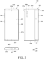
- FIG. 2 is a diagram illustrating an electronic device in a closed state according to an embodiment of the disclosure.
- FIG. 3 is a diagram illustrating an electronic device in an opened state according to an embodiment of the disclosure.
- FIG. 2 is a diagram illustrating a state in which a second display area 232 is accommodated in a housing 202.
- FIG. 3 is a diagram illustrating a state in which at least a portion of the second display area 232 is visually exposed to the outside of the housing 202.
- the state illustrated in FIG. 2 may be defined as a first housing 210 being closed with respect to a second housing 220, and the state illustrated in FIG. 3 may be defined as the first housing 210 being open with respect to the second housing 220.
- a "closed state” or an “opened state” may be defined as a state in which an electronic device is closed or opened.
- an electronic device 200 may include the housing 202.
- the housing 202 may include the second housing 220 and the first housing 210 movable relative to the second housing 220. In a certain embodiment, it may be interpreted as a structure in which the second housing 220 is disposed slidably on the first housing 210 in the electronic device 200.
- the first housing 210 may be disposed to reciprocate by a predetermined distance in a direction illustrated with respect to the second housing 220, for example, in a direction indicated by an arrow CD.
- the configuration of the electronic device 200 in FIGS. 2 and 3 may be wholly or partially identical to that of the electronic device 101 in FIG. 1 .
- the first housing 210 may be referred to as, for example, a first structure, a slide part, or a slide housing, and may be disposed to be reciprocable with respect to the second housing 220.
- the second housing 220 may be referred to as, for example, a second structure, a main part, or a main housing.
- the second housing 220 may accommodate at least a portion of the first housing 210 and guide sliding of the first housing 101.
- the second housing 220 may accommodate various electric and electronic components such as a main circuit board or a battery.
- a portion (e.g., a first display area 231) of a display 230 may be visually exposed to the outside of the housing 202.
- the first housing 210 moves (e.g., slides) with respect to the second housing 220
- another portion e.g., the second display area 232
- the display 230 may be accommodated into the second housing 220 (e.g., a slide-in operation) or visually exposed to the outside of the second housing 220 (e.g., a slide-out operation).
- the first housing 210 may include first sidewalls 211a, 211b, and 211c to surround at least a portion of the display 230 and/or a multi-bar structure (e.g., a multi-bar structure 208 in FIG. 4 ).
- the first sidewalls 211a, 211b, and 211c may extend from a first support member 211.
- the first sidewalls 211a, 211b, and 211c may include a (1-1) th sidewall 211a, a (1-2) th sidewall 211b opposite to the (1-1) th sidewall 211a, and a (1-3) th sidewall 211c extending from the (1-1) th sidewall 211a to the (1-2) th sidewall 211b.
- the (1-3) th sidewall 211c may be substantially perpendicular to the (1-1) th sidewall 211a and/or the (1-2) th sidewall 211b.
- the electronic device 200 is in the closed state (e.g., FIG.
- the (1-1) th sidewall 211a may face a (2-1) th sidewall 221a of the second housing 220
- the (1-2) th sidewall 211b may face a (2-2) th sidewall 221b of the second housing 220.
- the first support member 211, the (1-1) th sidewall 211a, the (1-2) th sidewall 211b, and/or the (1-3) th sidewall 211c may be integrally formed.
- the first support member 211, the (1-1) th sidewall 211a, the (1-2) th sidewall 211b, and/or the (1-3) th sidewall 211c may be formed as separate housings and combined or assembled.
- the second housing 220 may include second sidewalls 221a, 221b, and 221c to surround at least a portion of the first housing 210.
- the second sidewalls 221a, 221b, and 221c may extend from a rear plate 221.
- the second sidewalls 221a, 221b, and 221c may include the (2-1) th sidewall 221a, the (2-2) th sidewall 221b opposite to the (2-1) th sidewall 221a, and a (2-3) th sidewall 221c extending from the (2-1) th sidewall 221a to the (2-2) th sidewall 221b.
- the (2-3) th sidewall 221c may be substantially perpendicular to the (2-1) th sidewall 221a and/or the (2-2) th sidewall 221b.
- the (2-1) th sidewall 221a may face the (1-1) th sidewall 211a
- the (2-2) th sidewall 221b may face the (1-2) th sidewall 211b.
- the (2-1) th sidewall 221a may cover at least a portion of the (1-1) th sidewall 211a
- the (2-2) th sidewall 221b may cover at least a portion of the (1-2) th sidewall 211b.
- each of the (2-1) th sidewall 221a, the (2-2) th sidewall 221b, and the (2-3) th sidewall 221c may be formed with one surface (e.g., a front surface) open to accommodate (or surround) at least a portion of the first housing 210.
- the first housing 210 may be connected to the second housing 220, at least partially surrounded by the second housing, and may slide in the direction of the arrow 1 while being guided by the second housing 220.
- the rear plate 221, the (2-1) th sidewall 221a, the (2-2) th sidewall 221b, and/or the (2-3) th sidewall 221c may be integrally formed.
- the rear plate 221, the (2-1) th sidewall 221a, the (2-2) th sidewall 221b, and/or the (2-3) th sidewall 221c may be formed into separate housings and combined or assembled.
- the rear plate 221 and/or the (2-3) th sidewall 221c may cover at least a portion of the display 230.
- the display 230 may be accommodated into the second housing 220, and the rear plate 221 and/or the (2-3) th sidewall 221c may cover a portion of the display 230 accommodated in the second housing 220.
- the electronic device 200 may include the display 230.
- the display 230 may be interpreted as a flexible display or a rollable display.
- at least a portion (e.g., the second display area 232) of the display 230 may be slidable based on the sliding of the first housing 210.
- the display 230 may include or be disposed adjacent to a touch detection circuit, a pressure sensor capable of measuring the intensity (pressure) of a touch, and/or a digitizer capable of detecting a magnetic stylus pen.
- the configuration of the display 230 in FIGS. 2 and 3 may be wholly or partially identical to that of the display module 160 in FIG. 1 .
- the display 230 may include the first display area 231 and the second display area 232. According to an embodiment, at least a portion of the first display area 231 may be disposed on the second housing 220.
- the first display area 231 may be an area always visible to the outside.
- the first display area 231 may be interpreted as an area that may not be located within the housing 202.
- the second display area 232 may extend from the first display area 231, and may be inserted or accommodated into the second housing 220 or visually exposed to the outside of the second housing 220, according to the sliding of the first housing 210.
- the second display area 232 may be accommodated into the second housing or a space formed between the first housing 210 and the second housing or visually exposed to the outside, by moving while being guided by the multi-bar structure (e.g., the multi-bar structure 208 in FIG. 4 ) mounted substantially within the first housing 210.
- the second display area 232 may move based on sliding of the first housing 210 in a width direction (e.g., the direction indicated by the arrow (D) of the first housing 210.
- a width direction e.g., the direction indicated by the arrow (D) of the first housing 210.
- at least a portion of the second display area 232 may be unfolded or rolled together with the multi-bar structure 208 based on the sliding of the first housing 210.
- the second display area 232 when the first housing 210 moves from the closed state to the opened state, the second display area 232 may gradually be exposed to the outside of the housing 202 and form a substantially planar surface with the first display area 231, as viewed from above the first housing 210. In an embodiment, the second display area 232 may be at least partially accommodated into the first housing 210 and/or the second housing 220.
- the electronic device 200 may include at least one key input device 218, a connector hole 243, audio modules 247a and 247b, or camera modules 249a and 249b. While not shown, the electronic device 200 may further include an indicator (e.g., an LED device) or various sensor modules.
- an indicator e.g., an LED device
- the configurations of the audio modules 247a and 247b, and the camera modules 249a and 249b in FIGS. 2 and 3 may be wholly or partially identical to those of the audio module 170 and the camera module 180 in FIG. 1 .
- key input devices 218 may be located in an area of the first housing 210.
- the electronic device 200 may be designed to be without the illustrated key input devices 218, or to include additional key input device(s).
- the electronic device 200 may include a key input device not shown, such as a home key button or a touch pad disposed around the home key button.
- at least some of the key input devices 218 may be disposed on the second housing 220.
- the connector hole 227 may accommodate a connector (e.g., a USB connector) for transmitting and receiving power and/or data to and from an external electronic device.
- the electronic device 200 may include a plurality of connector holes 227, and some of the plurality of connector holes 227 may function as a connector hole for transmitting and receiving audio signals to and from an external electronic device.
- the connector hole 227 is disposed on the (2-3) th sidewall 221c, to which the disclosure is not limited, and the connector hole 227 or connector holes not shown may be disposed on the (2-1) th sidewall 221a or the (2-2) th sidewall 221b.
- the audio modules 247a and 247b may include at least one speaker hole 247a or at least one microphone hole 247b.
- One of speaker holes 247a may be provided as an external speaker hole, and another (not shown) may be provided as a receiver hole for voice calls.
- the electronic device 200 may include a microphone for obtaining a sound, and the microphone may obtain a sound external to the electronic device 200 through the microphone hole 247b.
- the electronic device 200 may include a plurality of microphones to detect the direction of a sound.
- the electronic device 200 may include an audio module in which the speaker hole 247a and the microphone hole 247b are implemented as a single hole, or may include a speaker (e.g., a piezo speaker) without the speaker hole 247a.
- a speaker e.g., a piezo speaker
- the camera modules 249a and 249b may include a first camera module 249a and/or a second camera module 249b.
- the second camera module 249b may be located in the second housing 220 and capture a subject in a direction opposite to the first display area 231 of the display 230.
- the electronic device 200 may include a plurality of camera modules 249a and 249b.
- the electronic device 200 may include at least one of a wide-angle camera, a telephoto camera, or a close-up camera, and may include an IR projector and/or an IR receiver to measure a distance to a subject according to an embodiment.
- the camera modules 249a and 249b may include one or more lenses, an image sensor, and/or an ISP.
- the electronic device 200 may further include another camera module (e.g., the first camera module 249a such as a front camera) that captures a subject from the opposite direction of the second camera module 249b.
- the first camera module 249a may be disposed around the first display area 231 or in an area overlapping with the first display area 231. When disposed in an area overlapping with the display 230, the first camera module 249a may capture a subject through the display 230.
- the indicator (not shown) of the electronic device 200 may be disposed in the first housing 210 and/or the second housing 220, and include an LED to provide state information about the electronic device 200 as a visual signal.
- a sensor module e.g., the sensor module 176 in FIG. 1
- the sensor module may generate an electrical signal or data value corresponding to an internal operational state of the electronic device 200 or an external environmental state.
- the sensor module may include, for example, a proximity sensor, a fingerprint sensor, or a biometric sensor (e.g., an iris/facial recognition sensor or an HRM sensor).
- the electronic device 200 may further include at least one of a gesture sensor, a gyro sensor, a barometric pressure sensor, a magnetic sensor, an acceleration sensor, a grip sensor, a color sensor, an IR sensor, a temperature sensor, a humidity sensor, or an illuminance sensor.
- FIG. 4 is an exploded perspective view illustrating an electronic device according to one of embodiments of the disclosure.
- the electronic device 200 may include the first housing 210, the second housing 220, the display 230, and the multi-bar structure 208.
- a portion (e.g., the second display area 232) of the display 230 may be accommodated into the electronic device 200, while being guided by the multi-bar structure 208.
- the configurations of the first housing 210, the second housing 220, and the display 230 in FIG. 4 may be wholly or partially identical to those of the first housing 210, the second housing 220, and the display 230 in FIG. 2 and/or FIG. 3 .
- the first housing 210 may include the first support member 211 (e.g., a slide plate). According to an embodiment, the first support member 211 may be slidably connected to the second housing 220. According to an embodiment, the first support member 211 may include a metallic material and/or a non-metallic (e.g., polymer) material.
- the first housing 210 may include at least one guide rail 213.
- the guide rail 213 may guide movement of the multi-bar structure 208.
- the guide rail 213 may include a groove or recess to accommodate at least a portion of the multi-bar structure 208 therein, and the guide rail 213 may slide with respect to the second housing 220, with at least a portion thereof accommodated in the guide rail 213.
- the guide rail 213 may be disposed on the first support member 211 and/or the first sidewalls 211a and 211b.
- the guide rail 213 may include a first guide rail 213a disposed on the (1-1) th sidewall 211a and a second guide rail 213b disposed on the (1-2) th sidewall 211b.
- at least a portion of the first guide rail 213a may be located between the (1-1) th sidewall 211a and the multi-bar structure 208
- at least a portion of the second guide rail 213b may be located between the (1-2) th sidewall 211b and the multi-bar structure 208.
- the multi-bar structure 208 may move with respect to the second housing 220.
- the closed state e.g., FIG. 2
- the multi-bar structure 208 may be substantially accommodated within the second housing 220.
- the multi-bar structure 208 may be interpreted as a multi-joint hinge structure.
- the multi-bar structure 208 may include a plurality of bars or rods 209.
- the plurality of rods 209 may extend in a straight line and be arranged along a direction in which the first housing 210 slides.
- each rod 209 may revolve around an adjacent other rod 209 while remaining parallel to the adjacent other rod 209.
- the plurality of rods 209 may be arranged to form a curved shape or a planar shape.
- a portion of the multi-bar structure 208, which faces the (1-3) th sidewall 211c may form a curved surface
- another portion of the multi-bar structure 208, which does not face the (1-3) th sidewall 211c may form a flat surface.
- the second display area 232 of the display 230 may be mounted or supported on the multi-bar structure 208.
- the multi-bar structure 208 may form a substantially flat surface, thereby supporting or maintaining the second display area 232 in a flat state.
- the multi-bar structure 208 may be replaced with a bendable integrated support member (not shown).
- the multi-bar structure 208 may be interpreted as a multi-joint hinge structure.
- the second housing 220 may include the rear plate 221, a display support plate 223, and/or a second support member 225.
- the rear plate 221 may form at least a portion of the exterior of the second housing 220 or the electronic device 200.
- the rear plate 221 may provide a decorative effect to the exterior of the electronic device 200.
- the display support plate 223 may support at least a portion of the display 230.
- the first display area 231 may be disposed on the display support plate 223.
- the display support plate 223 may be interpreted as a second display support member.
- the second support member 225 may support a component (e.g., a battery 204 and/or a PCB 205) of the electronic device 200.
- a component e.g., a battery 204 and/or a PCB 205
- the battery 204 and the PCB 205 may be disposed between the display support plate 223 and the second support member 225.
- at least a portion of the first housing 210 may be disposed between the display support plate 223 and the second support member 225.
- the second housing 220 e.g., the rear plate 221, the display support plate 223, and/or the second support member 225
- the rear plate 221 and the second support member 225 may be integrally formed.
- the PCB 205 may accommodate at least one (e.g., the processor 120 in FIG. 1 ) of the components of the electronic device 200.
- the battery 204 may supply power to at least one (e.g., the processor 120 in FIG. 1 ) of the components of the electronic device 200.
- the electronic device 200 may include a display support member 233.
- the display support member 233 may be disposed within the first housing 210.
- the display support member 233 may be slidable together with the first housing 210 with respect to the second housing 220.
- the display support member 233 may support at least a portion (e.g., the first display area 232) of the display 230 and/or at least a portion of the multi-bar structure 208.
- at least a portion of the display 230 and/or at least a portion of the multi-bar structure 208 may be disposed between the first support member 211 of the first housing 210 and the display support member 233.
- the display support member 233 may be connected to the first housing 210.
- the display support member 233 may be disposed on the first support member 211, and at least a portion thereof may be disposed substantially parallel to the (1-3) th sidewall 211c.
- the display support member 233 may be interpreted as a portion of the first housing 210.
- the display support member 233 may be interpreted as a display support bar (DSB).
- FIGS. 2 to 4 has a rollable or slidable appearance
- the disclosure is not limited thereto. According to an embodiment (not shown), at least a portion of the illustrated electronic device may be rolled into a scroll shape.
- FIG. 5 is a projection view illustrating the interior of an electronic device in a closed state according to an embodiment of the disclosure.
- FIG. 6 is a projection view illustrating the interior of an electronic device in an opened state according to an embodiment of the disclosure.
- the electronic device 200 may include the second housing 220, the display support member 233, a power transmission unit 300, a switching unit 410, and a motor unit 500.
- the configurations of the housing 220 and the display support member 233 in FIGS. 5 and 6 may be wholly or partially identical to those of the second housing 220 and the display support member 233 in FIG. 4 .
- the electronic device 200 may be opened or closed using the power transmission unit 300 and/or the motor unit 500.
- the distance between the first housing (e.g., the first housing 210 in FIG. 2 ) and the second housing 220 may change based on a driving force generated by the motor unit 500.
- the display support member 233 may move with respect to the second housing 220 based on movement of the power transmission unit 300.
- the display support member 233 may be connected to the first housing 210.
- the first housing 210 may be movable together with at least a portion of the display support member 233, with respect to the second housing 220.
- the power transmission unit 300 may mechanically connect the first housing (e.g., the first housing 210 in FIG. 2 ) (or the display support member 233) to the second housing 220.
- the power transmission unit 300 may transmit at least a portion of the driving force generated by the motor unit 500 from the second housing 220 to the first housing 210.
- the power transmission unit 300 may include a gear assembly 301 with at least one gear and a gear housing 303 surrounding at least a portion of the gear assembly 301.
- the gear assembly 301 may include a pinion gear 350 configured to rotate by the driving force generated by the motor unit 500 and a rack gear 360 configured to be meshed with the pinion gear 350.
- the pinion gear 350 may be connected to the second housing 220, and the rack gear 360 may be connected to the display support member 233.
- the rack gear 360 when the motor unit 500 generates a driving force, the pinion gear 360 connected to the motor unit 500 may rotate while being connected to the second housing 220, and the rack gear 360 may slide based on the rotation of the pinion gear 360.
- the rack gear 360 may slide together with the display support member 233 with respect to the second housing 220.
- the rack gear 360 may be connected to the display support member 233 using at least one fastening member (e.g., screw) 361.
- the switching unit 410 may control movement of the power transmission unit 300.
- the switching unit 410 may include a motor (e.g., a first motor 413) and move based on a driving force (e.g., a second driving force) generated by the motor.
- a driving force e.g., a second driving force
- the switching unit 410 may reduce or prevent rotation of the gear housing 303 by contacting the gear housing 303.
- the switching unit 410 may maintain the gear housing 303 rotatable by being spaced apart from the gear housing 303.
- the switching unit 410 may include a first part 411 configured to be slidable in a first direction D1 using the second driving force generated by the first motor 413.
- the first direction D1 may be substantially perpendicular to the sliding direction of the electronic device 200.
- the first direction D1 may be substantially parallel to a longitudinal direction (e.g., Y-axis direction) of the electronic device 200.
- the first part 411 may be connected to the first motor 413.
- the switching unit 410 may include a second part 412 that may contact at least a portion of the gear housing 303.
- the second part 412 may be rotatably connected to the second housing based on sliding of the first part 411. For example, the second part 412 may rotate around a rotation axis structure 412a.
- the switching unit 410 may include the first motor 413 configured to generate the second driving force to move the first part 411.
- the first motor 413 may be a linear motor.
- the first motor 413 may be connected to the second housing 220.
- the size of the first motor 413 may be smaller than the size of the motor unit 500.
- the motor unit 500 may generate a driving force for a sliding operation of the electronic device 200.
- the motor unit 500 may include a stator and a rotor.
- the motor unit 500 may be connected to the second housing 220. At least a portion of the driving force generated by the motor unit 500 may be transmitted to the display support member 233 using the power transmission unit 300.
- the electronic device 200 may include a heat dissipation structure 700 to reduce a temperature inside the electronic device 200.
- the heat dissipation structure 700 may include at least one fan.
- the heat dissipation structure 700 may be connected to the motor unit 500.
- the fan of the heat dissipation structure 700 may rotate based on the driving force generated by the motor unit 500.
- the processor 120 may adjust movement of the switching unit 410 when there is a user input to operate the fan or when the processor (e.g., the processor 120 in FIG. 1 ) determines that it is necessary to lower the internal temperature of the electronic device 200, the processor 120 may adjust movement of the switching unit 410.
- the processor 120 may keep the gear housing 303 rotatable by separating the switching unit 410 from the gear housing 303. At this time, the fan of the heat dissipation structure 700 may rotate based on the driving force generated by the motor unit 500 without movement of the first housing 210 or the second housing 220.
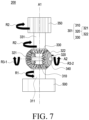
- FIG. 7 is a diagram illustrating a connection relationship between a motor unit and a power transmission unit according to an embodiment of the disclosure.
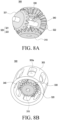
- FIGS. 8A and 8B are perspective views illustrating a power transmission unit according to an embodiment of the disclosure.
- FIG. 8A is a perspective view illustrating the power transmission unit 300 including the gear assembly 301
- FIG. 8B is a perspective view illustrating the power transmission unit 300 including the gear assembly 301 and the gear housing 303.
- the power transmission unit 300 may include at least one gear (e.g., a first gear 310, a second gear 320, and a third gear 330) and a gear shaft 340.
- the configuration of the power transmission unit 300 in FIG. 7 , FIG. 8A , and/or FIG. 8 may be wholly or partially identical to that of the power transmission unit 300 in FIG. 5 .
- the power transmission unit 300 may include the first gear 310, at least one second gear 320, the third gear 330, the gear shaft 340, and the pinion gear 350 (e.g., the pinion gear 350 in FIG. 5 ).
- the first gear 310, the at least one second gear 320, and/or the third gear 330 may be a bevel gear.
- the first gear 310 may be connected to the motor unit 500.
- the first gear 310 may rotate around a first rotation axis A1 based on the driving force generated by the motor unit 500.
- the power transmission unit 300 may include a first shaft 311 rotatable around the first rotation axis A1.
- the first shaft 311 may be connected to the motor unit 500 and/or the first gear 310.
- power generated by the motor unit 500 may be transmitted to the first gear 310 through the first shaft 311.
- the at least one second gear 320 may be meshed with the first gear 310 and/or the third gear 330.
- the second gear 320 may rotate based on the rotation of the first gear 310 and/or the third gear 330.
- the at least one second gear 320 may include a (2-1) th gear 321 and a (2-2) th gear 322 arranged substantially parallel to the (2-1) th gear 321.
- the second gear 320 e.g., the (2-1) th gear 321 and the (2-1) th gear 322) may be connected to the gear housing 303 using the gear shaft 340.
- the second gear 320 may be rotatably connected to the gear shaft 340.
- the second gear 320 may include a through hole (not shown), and the gear shaft 340 may pass through the through hole (not shown).
- the gear shaft 340 may provide a second rotation axis A2 for rotation of the second gear 320.
- the second gear 320 in a first state in which the switching unit 410 is in contact with the gear housing 303, the second gear 320 may rotate around the second rotation axis A2 in a third rotation direction R3-1 and R3-2 substantially perpendicular to a first rotation direction R1 in which the first gear 310 rotates or a second rotation direction R2 in which the third gear 330 rotates.
- the gear housing 303, the second gear 320, and the gear shaft 340 may rotate around the first rotation axis A1 along the first direction R1 in which the first gear 310 rotates.
- the gear shaft 340 may be connected to the second gear 320 and the gear housing 303.
- a (3-1) th rotation direction R-1 of the (2-1) th gear 321 may be opposite to a (3-2) th rotation direction R-2 of the (2-2) th gear 322.
- the gear housing 303 may include at least one recess 303a.
- the recess 303a may be a through hole and/or a groove.
- the third gear 330 may be meshed with the at least one second gear 320.
- the third gear 330 may rotate based on the rotation of the second gear 320 or rotate the second gear 320.
- the third gear 330 may rotate around the first rotation axis A1.
- the rotation direction (e.g., the first rotation direction R1) of the first gear 310 and the rotation direction (e.g., the second rotation direction R2) of the third gear 330 may be different.
- the second rotation direction R2 may be clockwise.
- the power transmission unit 300 may include a second shaft 331 rotatable around the first rotation axis A1.
- the second shaft 331 may be connected to the third gear 330 and/or the pinion gear 350.
- at least a portion of power received by the third gear 330 may be transmitted to the pinion gear 350 through the second shaft 331.
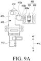
- FIG. 9A is a diagram illustrating a connection state between a switching unit and a power transmission unit in an automatic state according to an embodiment of the disclosure.
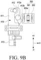
- FIG. 9B is a diagram illustrating a connection state between the switching unit and the power transmission unit in a manual state according to an embodiment of the disclosure.
- the electronic device 200 may include the power transmission unit 300 and the switching unit 410 to control rotation of the power transmission unit 300.
- the configurations of the power transmission unit 300 and the switching unit 410 in FIGS. 9A and 9B may be wholly or partially identical to those of the power transmission unit 300 and the switching unit 410 in FIG. 5 .
- the switching unit 410 may control movement of the power transmission unit 300. For example, the switching unit 410 may reduce or prevent rotation of the gear housing 303 by being connected to the gear housing 303 in the first state (e.g., FIG. 9A ). The switching unit 410 may keep the gear housing 303 rotatable by being spaced apart from the gear housing 303 in the second state (e.g., FIG. 9B ).
- the first state may be interpreted as an automatic state in which the electronic device 200 is automatically opened.
- the second state may be interpreted as a manual state in which the electronic device 200 is manually opened.
- the processor e.g., the processor 120 in FIG. 1
- the processor 120 may move the switching unit 410 to switch the state of the electronic device 200 to the first state in which the switching unit 410 is in contact with the gear housing 303 or to the second state in which the switching unit 410 is spaced apart from the gear housing 303.
- the switching unit 410 in the first state (e.g., FIG. 9A ), at least a portion (e.g., the second part 412) of the switching unit 410 may be inserted into the recess 303a of the gear housing 303.
- the gear housing 303 and the gear shaft 340 may be fixed without rotating, even though the gear assembly 301 rotates.
- the gear housing 303 in the second state (e.g., FIG. 9B ) in which the switching unit 410 is spaced apart from the gear housing 303, the gear housing 303 may rotate together with at least a portion of the gear assembly 301 based on rotation of the gear assembly 301.
- the second part 412 of the switching unit 410 may fix at least a portion of the gear housing 303.
- an end portion 412b of the second part 412 may be inserted into the recess 303a of the gear housing 303.
- the second part 412 of the switching unit 410 in the second state in which the first part 411 of the switching unit 410 moves in a +Y direction, the second part 412 of the switching unit 410 may be spaced apart from the gear housing 303.
- the processor e.g., the processor 120 of FIG. 1
- the processor 120 may adjust the position of the switching unit 410 so that the second part 412 of the switching unit 410 is accommodated in a recess 303a.
- memory e.g., memory 130 in FIG. 1
- the processor 120 may move the switching unit 410 based on the recess information. For example, the processor 120 may move the switching unit 410 such that the second part 412 of the switching unit 410 is inserted into a recess 303a, without contacting one surface of the gear housing 303.
- the second part 412 may include a brake pad and prevent or reduce the rotation of the gear housing 303 using a frictional force.
- the switching unit 410 may prevent or reduce the rotation of the gear housing 303 using a hook structure (not shown).
- the switching unit 410 and/or the gear housing 303 may include at least one magnetic material to prevent or reduce the rotation of the gear housing 303.
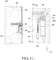
- FIG. 10 is a diagram illustrating the interior of an electronic device including a deformable member according to an embodiment of the disclosure.
- FIG. 11A is a diagram illustrating a connection state between a switching unit and a power transmission unit in an automatic state according to an embodiment of the disclosure.
- FIG. 11B is a diagram illustrating a connection state between a switching unit and a power transmission unit in a manual state according to an embodiment of the disclosure.
- the electronic device 200 may include the second housing 220, the display support member 233, the power transmission unit 300, a switching unit 420, and the motor unit 500.
- the configurations of the second housing 220, the display support member 233, the power transmission unit 300, the switching unit 420, and the motor unit 500 in FIG. 10 , FIG. 11A , and/or FIG. 11B may be wholly or partially identical to those of the second housing 220, the display support member 233, the power transmission unit 300, the switching unit 410, and the motor unit 500 in FIG. 5 .
- the switching unit 420 may control movement of the power transmission unit 300.
- the switching unit 420 may include at least one deformable member 423 and move based on the shape deformation of the deformable member 423.
- the switching unit 420 may contact the gear housing 303 or be spaced apart from the gear housing 303 based on the shape deformation of the deformable member 423.
- the rotation of the gear housing 303 may be reduced or prevented.
- the gear housing 303 may rotate with respect to at least a portion (e.g., the first gear 310 and/or the third gear 330) of the gear assembly 301.
- the switching unit 420 may rotate around a third rotation axis A3 (e.g., the rotation axis structure 412a in FIG. 5 ).
- the switching unit 420 may include a third area 421 configured to contact the gear housing 303, and a fourth area 422 located opposite to the third area 421 with respect to the third rotation axis A3.
- the fourth area 422 may be connected to the deformable member 423.
- at least a portion of the switching unit 420 may rotate around the second rotation axis A2 based on a change in the length of the deformable member 423.
- the length of the deformable member 423 may decrease, and the fourth area 422 of the switching unit 420 may be moved toward the power supply module 424, so that the third area 421 of the switching unit 420 may be spaced apart from the gear housing 303.
- the deformable member 423 may include a shape memory alloy (SMA).
- SMA shape memory alloy
- the shape of the deformable member 423 may be changed to a specified shape based on a temperature.
- the deformable member 423 may include nickel (Ni) and/or titanium (Ti), and may be changed to a shape of austenite, twinned martensite, or modified martensite based on a temperature and/or a force applied to the deformable member 423.
- the deformable member 423 may include copper (Cu), zinc (Zn), and/or aluminum (Al).
- the switching unit 420 may include the power supply module 424.
- the power supply module 424 may be electrically connected to the processor (e.g., the processor 120 in FIG. 1 ), and the processor 120 may provide current to the deformable member 423 based on information obtained using a sensor module (e.g., the sensor module 176 in FIG. 1 ).
- the temperature of the deformable member 423 may be increased by the current transmitted from the power supply module 424.
- the shape or length of the deformable member 423 in a first state in which the deformable member 423 is heated e.g., FIG. 11A
- the shape or length of the deformable member 423 in a second state in which the deformable member 423 is not heated e.g., FIG. 11B ).
- the switching unit 420 may include at least one elastic member (e.g., spring) (not shown).
- the at least one elastic member when the power supply module 424 does not provide current, the at least one elastic member may reduce or prevent movement of the switching unit 420.
- the first state e.g., FIG. 11A
- the movement of the switching unit 420 may be reduced by the at least one elastic member.
- a force caused by the length change of the deformable member 423 may be greater than an elastic force provided to the switching unit 420 by the at least one elastic member.
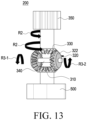
- FIGS. 12 and 13 are diagrams illustrating an operation of a power transmission unit in a second state according to an embodiment of the disclosure.
- FIG. 12 is a diagram illustrating an operation of the power transmission unit 300 in the second state, when the motor unit 500 of the electronic device is driven.
- FIG. 13 is a diagram illustrating an operation of the power transmission unit 300, when a force is applied to the electronic device from the outside of the electronic device.
- the second state may be interpreted as a state in which the gear housing (e.g., the gear housing 303 in FIG. 9B ) and the switching unit (e.g., the switching unit 410 in FIG. 9B ) are spaced apart from each other.
- the electronic device 200 may include the power transmission unit 300 including the gear assembly 301, and the motor unit 500.
- the gear assembly 301 may include the first gear 310, the at least one second gear 320, the third gear 330, the gear shaft 340, and the pinion gear 350.
- the configurations of the power transmission unit 300 and the motor unit 500 in FIGS. 12 and 13 may be wholly or partially identical to those of the power transmission unit 300 and the motor unit 500 in FIGS. 5 to 7 .
- the third gear 330 and/or the pinion gear 350 may operate independently of the motor unit 500.
- the at least one second gear 320 and the gear shaft 340 may rotate based on the rotation of the first gear 310, and the third gear 330 and/or the pinion gear 350 may not rotate.
- the first housing e.g., the first housing 210 in FIG. 2
- the second housing e.g., the second housing 220 in FIG. 2 .
- the at least one second gear 320 and the gear shaft 340 may rotate around the first rotation axis A1, and the third gear 330 and the pinion gear 350 may not move.
- the magnitude (e.g., 3kgf) of a force required to rotate the pinion gear 350 e.g., a frictional force between the pinion gear 350 and the rack gear (e.g., the rack gear 360 in FIG. 5 ) and/or a repulsive force of the display (e.g., the display 230 in FIG.
- the third gear 330 may not rotate with respect to the first gear 310.
- the third gear 330 and/or the pinion gear 350 may rotate by an external force applied from the outside of the electronic device 200.
- the rack gear 360 may move together with the first housing 210, and the pinion gear 350 and/or the third gear 330 may rotate around the first rotation axis A1 in a fourth direction R based on the sliding of the rack gear 360.
- the third gear 330 rotates, the at least one second gear 320 and the gear shaft 340 may rotate around the first rotation axis A1, and the first gear 310 may not move.
- the magnitude (e.g., about 0.6 to 1kgf) of a force required for the rotation of the first gear 310 may be greater than the magnitude of a force required for the rotation of the second gear 320 with respect to the first gear 310 or the third gear 330 (e.g., a frictional force between the second gear 320 and the first gear 310 and/or a frictional force between the second gear 320 and the third gear 330).
- the at least one second gear 320, the gear shaft 340, and the gear housing e.g., the gear housing 303 in FIG. 5
- the first gear 310 may not rotate with respect to the third gear 330.
- a force required to rotate a gear located within the motor unit 500 may be reduced.
- a force (about 0.6 to 1.4kgf) required to rotate a reduction gear located within the motor unit 500 may be reduced.
- a force required to open the electronic device 200 may be reduced, and user convenience may be increased.
- the second state as the third gear 330 and/or the pinion gear 350 rotates independently of the first gear 310 and/or the motor unit 500, breakage of the motor unit 500 caused by an external force applied to the electronic device 200 may be reduced or prevented.
- the second state may be interpreted as a state in which a user manually opens or closes the electronic device 200, or an external force (e.g., a repulsive force from a collision with the ground) is applied to the electronic device 200.
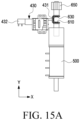
- FIG. 14 is a projection view illustrating the interior of an electronic device including a switching unit with a fourth gear in a closed state according to an embodiment of the disclosure.
- FIG. 15A is an enlarged view illustrating an electronic device in a first state according to an embodiment of the disclosure
- FIG. 15B is an enlarged view illustrating the electronic device in a second state according to an embodiment of the disclosure
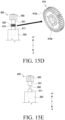
- FIG. 15C is a diagram illustrating a connection relationship between a first gear and a third gear according to an embodiment of the disclosure
- FIG. 15D is a diagram illustrating a connection relationship between the first gear and the third gear according to another embodiment of the disclosure
- FIG. 15E is a diagram illustrating a connection relationship between the first gear and the third gear according to another embodiment of the disclosure.
- the electronic device 200 may include the second housing 220, the display support member 233, a power transmission unit 600, a switching unit 430, and the motor unit 500.
- the configurations of the second housing 220, the display support member 233, the power transmission unit 600, the switching unit 430, and the motor unit 500 in FIG. 14 , FIG. 15A , FIG. 15B, FIG. 15C , FIG. 15D , and/or FIG. 15E may be wholly or partially identical to those of the second housing 220, the display support member 233, the power transmission unit 300, the switching unit 410, and the motor unit 500 in FIG. 5 .
- the power transmission unit 600 may include a first shaft 611 connected to the motor unit 500, a first gear 610, a third gear 630, and a third shaft 631 connected to a pinion gear 650.
- the first gear 610 and the third gear 630 may be disposed to be spaced apart from each other, substantially parallel to each other.
- the configurations of the first gear 610, the first shaft 611, the third gear 630, the second shaft 631, and the pinion gear 650 may be substantially the same as those of the first gear 310, the first shaft 311, the third gear 330, the second shaft 331, and the pinion gear 350 in FIG. 5 and/or FIG. 7 .
- the switching unit 430 may include a fourth gear 431 facing the first gear 610 and the third gear 630.
- the switching unit 430 may include a first motor 432 to move the switching unit 430.
- at least a portion (e.g., the fourth gear 431) of the switching unit 430 may slide in a width direction (e.g., an X-axis direction) of the electronic device 200 based on a driving force of the first motor 432.
- the first motor 432 may be a linear motor.
- the fourth gear 431 may be in contact with the first gear 610 and/or the third gear 630 in a first state (e.g., FIG. 15A ).
- a driving force generated by the motor unit 500 may be transmitted to the third gear 630 through the first gear 610 and the fourth gear 431.
- the fourth gear 431 may be spaced apart from the second gear 610 and the third gear 630 in a second state (e.g., FIG. 15B ).
- a driving force generated by the motor unit 500 may not be transmitted to the third gear 630.
- a force caused by sliding of the display support member 233 may not be transmitted to the motor unit 500.
- the first gear 610 may move in the longitudinal direction (e.g., Y-axis direction) of the electronic device 200 with respect to the third gear 630.
- the first gear 610 may move along a first rotation axis (e.g., the first rotation axis A1 in FIG. 7 ) using the first shaft 611 which is connected to the motor unit 500 by a screw structure.
- the first shaft 611 may move along the first rotation axis (e.g., the first rotation axis A1 in FIG. 7 ) using at least a portion (e.g., the first motor 432 in FIG.
- the switching unit e.g., the switching unit 410 in FIG. 6 .
- the third gear 630, the second shaft 631, and/or the pinion gear 650 may rotate based on power transmitted from the motor unit 500.
- the third gear 630 and/or the pinion gear 650 may rotate independently of the motor unit 500.
- the first gear 610 and the third gear 630 are shown as bevel gears, to which the shapes of the first gear 610 and the third gear 630 are not limited.
- the first gear 610 may include an outer gear 610b and an inner gear 610a.
- the outer gear 610b may be meshed with the third gear 630
- the inner gear 610a may be meshed with a gear formed on the outer periphery of the first shaft 611.
- the first shaft 611 may include a screw structure and move in the longitudinal direction (e.g., the Y-axis direction) along the first rotation axis (e.g., the first rotation axis A1 in FIG. 7 ), while being connected to the motor unit 500 using a screw structure.
- the first shaft 611 may move in the longitudinal direction (e.g., Y-axis direction) along the first rotation axis (e.g., the first rotation axis A1 in FIG. 7 ) using at least a portion (e.g., the first motor 432 in FIG. 15A ) of the switching unit (e.g., the switching unit 410 in FIG. 6 ).
- the first gear 610 may rotate together with the first shaft 611.
- the pinion gear 650 may receive power provided by the motor unit 500 using the first shaft 611, the first gear 610, the third gear 630, and the second shaft 631.
- the first gear 610 may rotate independently of the first shaft 611.
- the pinion gear 650 may rotate independently of the motor unit 500, without receiving power provided by the motor unit 500.
- the power transmission unit 600 may include at least one protrusion 660 to connect the first shaft 611 to the second shaft 631.
- the protrusion 660 may be connected to the first shaft 611, and may be connected to or disconnected from the second shaft 631 based on rotation of the motor unit 500.
- the first shaft 611 may include a screw structure and move along the first rotation axis (e.g., the first rotation axis A1 in FIG. 7 ), while being connected to the motor unit 500 using the screw structure.
- the protrusion 660 may include a screw structure and move along the first rotation axis (e.g., the first rotation axis A1 in FIG.
- the first shaft 611 and/or the protrusion 660 may move along the first rotation axis (e.g., the first rotation axis A1 in FIG. 7 ) using at least a portion (e.g., the first motor 432 in FIG. 15A ) of the switching unit (e.g., the switching unit 410 in FIG. 6 ).
- the pinion gear 650 and/or the second shaft 631 may rotate based on power transmitted from the motor unit 500.
- the pinion gear 650 may rotate independently of the motor unit 500.
- FIG. 16 is a flowchart illustrating an operation 1100 of switching an operation mode of an electronic device according to an embodiment of the disclosure.
- the operation 1100 of switching an operation mode (or state) of the electronic device 200 may include determining whether the electronic device is in the opened state in operation 1100, switching to a first mode in operation 1120, detecting a specified input or a specified condition by the sensor module 176 in operation 1200, and/or switching to a second mode in operation 1130.
- the configurations of the electronic device 200 and the sensor module 176 in FIG. 16 may be wholly or partially identical to those of the electronic device 101 and the sensor module 176 in FIG. 1 .
- a processor may determine whether the electronic device 200 is in the opened state.
- the sensor module 176 may include a magnetic field sensor (e.g., a Hall sensor), a capacitive sensor, and/or an optical sensor module, and the processor 120 may determine whether the electronic device 200 is in the opened state (e.g., FIG. 2 ) or the closed state (e.g., FIG. 3 ) using information detected by the sensor module 176.
- the processor 120 may determine a slide distance of the electronic device 200.
- the processor 120 may switch the electronic device 200 to the first mode.
- the first mode may be interpreted as a state in which a switching unit (e.g., the switching unit 410 in FIG. 5 , the switching unit 420 in FIG. 10 , and/or the switching unit 430 in FIG. 14 ) and a power transmission unit (e.g., the power transmission unit 300 in FIG. 5 or FIG. 10 , and/or the power transmission unit 600 in FIG. 14 ) are in contact with each other.
- the first mode may be interpreted as an automatic mode or an automatic motor mode.
- the processor 120 may switch the electronic device 200 to the second mode.
- the second mode may be interpreted as a state in which the switching unit 410, 420, or 430 and the power transmission unit 300 or 600 are spaced apart from each other.
- the second mode may be interpreted as a manual mode.
- the sensor module 176 may perform operation 1130 to detect a specified input (e.g., a user input) or a specified condition (e.g., an internal temperature of the electronic device, drop, or a remaining battery capacity).
- the sensor module 176 may detect a user input provided on a key input device (e.g., the key input devices 218 in FIG. 2 ) and/or the display 230.
- the sensor module 176 may include a temperature sensor to detect an internal temperature of the electronic device 200.
- the sensor module 176 may include an acceleration sensor to detect an acceleration of the electronic device 200 and/or a gyro sensor to detect a direction in which the electronic device 200 is located.
- the sensor module 176 may include a current detection sensor to detect a remaining capacity of a battery (e.g., the battery 189 in FIG. 4 ).
- the sensor module 176 may include a pressure sensor to detect pressure applied to the electronic device 200 from the outside of the electronic device 200.
- the processor 120 may perform operation 1140 to switch the electronic device 200 to the second mode.
- the processor 120 may switch the electronic device 200 to the second mode.
- user convenience may be increased by allowing a user to selectively use the first mode or the second mode.
- the processor 120 may perform operation 1140 to switch the electronic device 200 to the second mode.
- the processor 120 may switch the electronic device 200 to the second mode.
- the temperature rise of the electronic device 200 may be reduced by heat generated by a motor unit (e.g., the motor unit 500 in FIG. 5 ) and/or the switching unit (e.g., switching unit 410 in FIG. 5 ), thereby reducing or preventing breakage of internal components of the electronic device 200.
- the processor 120 may switch the electronic device 200 to the second mode.
- the remaining capacity (state of charge) of the battery (e.g., the battery 204 in FIG. 4 ) of the electronic device 200 is equal to or less than a specified remaining capacity
- the processor 120 may switch the electronic device 200 to the second mode.
- power consumed by the motor unit (e.g., the motor unit 500 in FIG. 5 ) and/or the switching unit (e.g., the switching unit 410 in FIG. 5 ) may be reduced, and user convenience may be increased.
- the processor 120 may switch the electronic device 200 to the second mode. For example, the processor 120 may determine whether the electronic device 200 is falling based on information obtained using the sensor module 176 (e.g., a gyro sensor and/or an acceleration sensor). When determining that the electronic device 200 is falling, the processor 120 may switch the electronic device 200 to the second mode. In another example, after the electronic device 200 is subjected to an external impact, the processor 120 may switch the electronic device 200 to the second mode based on information obtained using the sensor module 176 (e.g., a pressure sensor).
- the sensor module 176 e.g., a gyro sensor and/or an acceleration sensor
- a force applied to the motor unit e.g., the motor unit 500 in FIG. 5
- a second housing e.g., the second housing 220 in FIG. 2
- a first housing e.g., the first housing 210 in FIG. 2
- breakage of the motor unit 500 e.g., the motor core
- FIGS. 17A and 17B are diagrams illustrating switching of an operation state of an electronic device according to an embodiment of the disclosure.
- the electronic device 200 may include the display 230.
- the configurations of the electronic device 200 and the display 230 in FIG. 17A and/or FIG. 17B may be wholly or partially identical to those of the electronic device 200 and the display 230 in FIG. 2 .
- the display 230 may display a usage mode switching icon 1001.
- the usage mode switching icon 1001 may indicate a first-mode (e.g., automatic-mode) state or a second-mode (e.g., manual-mode) state.
- the processor e.g., the processor 120 in FIG. 1
- the switching unit e.g., th switching unit 410 in FIG. 5 , the switching unit 420 in FIG. 10 , or the switching unit 430 in FIG. 14
- a user input e.g., a touch
- the automatic-mode state may be interpreted as a first mode in which the power transmission unit (e.g., the power transmission unit 300 in FIG. 5 ) is in contact with the switching unit 410, 420, or 430
- the manual-mode state may be interpreted as a second mode in which the power transmission unit (e.g., the power transmission unit 300 in FIG. 5 ) is spaced apart from the switching unit 410, 420, or 430.
- the electronic device 200 may display a usage mode switching notification 1002 to switch the state of the switching unit 410, 420, or 430.
- the processor e.g., the processor 120 in FIG. 1
- the processor 120 may output the usage mode switching notification 1002 using the display 230 based on information detected by the sensor module (e.g., the sensor module 176 in FIG. 1 ). For example, when the internal temperature of the electronic device 200 is higher than a specified temperature, or when the remaining capacity of the battery (e.g., the battery 205 in FIG. 4 ) of the electronic device 200 is less than a specified capacity, the processor 120 may provide the usage mode switching notification 1002 to the user.
- the processor 120 may switch the operation mode (e.g., the first mode or the second mode) of the electronic device 200 based on a user input applied to the usage mode switching notification 1002.
- the usage mode switching notification 1002 may include an area for outputting the usage mode switching notification 1002 on the display 230 again after a specified time (e.g., 30 minutes).
- An electronic device e.g., a portable terminal
- a display in the shape of a flat surface or both flat and curved surfaces.
- the electronic device with the display may be limited in realizing a screen larger than the size of the electronic device due to the fixed structure of the display. Accordingly, electronic devices including rollable displays have been studied.
- the electronic device may be rolled or slided manually using a user's force.
- the manual rolling or sliding may increase the user's fatigue level, thereby reducing user convenience.
- the rolling or sliding of the electronic device may be performed automatically using a driving force generated by a component of the electronic device.
- a component e.g., a motor
- an electronic device capable of operating in an automatic mode or a manual mode while reducing or preventing breakage of the electronic device may be provided.
- An electronic device may be switched to an automatic mode or a manual mode using a switching unit for controlling whether to rotate a gear housing.
- a switching unit for controlling whether to rotate a gear housing.
- the electronic device may be switched to the manual mode under a specified condition. For example, when the electronic device is dropped or overheated, the electronic device may be switched to the manual mode. In another example, when the remaining capacity of a battery of the electronic device is less than a specified capacity, the electronic device may be switched to the manual mode. As the electronic device is switched to the manual mode under the specified condition, damage to the electronic device may be reduced or prevented, or user convenience may be increased.
- an electronic device may include a housing (e.g., the first housing 202 in FIG. 2 ) including a first housing (e.g., the first housing 210 in FIG 2 ) and a second housing (e.g., the second housing 220 in FIG. 2 ) accommodating at least a portion of the first housing and guiding sliding of the first housing, a display (e.g., the display 230 in FIG. 2 ) configured to be at least partially unfolded based on sliding of the first housing, a motor unit (e.g., the motor unit 500 in FIG.
- a housing e.g., the first housing 202 in FIG. 2
- a first housing e.g., the first housing 210 in FIG 2
- a second housing e.g., the second housing 220 in FIG. 2
- a display e.g., the display 230 in FIG. 2
- a motor unit e.g., the motor unit 500 in FIG.
- a power transmission unit e.g., the power transmission unit 300 in FIG. 5
- a gear assembly e.g., the gear assembly 301 in FIG. 5
- a gear housing e.g., the gear housing 303 in FIG. 5
- a switching unit e.g., the switching unit 410 in FIG. 5 or the switching unit 420 in FIG. 10
- a sensor module e.g., the sensor module 176 in FIG.
- a processor e.g., the processor 120 in FIG. 1 ) configured to adjust a connection state between the switching unit and the gear housing based on the state or input detected by the sensor module.
- the power transmission unit may include a first gear (e.g., the first gear 310 in FIG. 8A ) connected to the motor unit, at least one second gear (e.g., the second gear 320 in FIG. 8A ) meshed with the first gear, a gear shaft (e.g., the gear shaft 340 in FIG. 8A ) rotatably connected to the at least one second gear, and a third gear (e.g., the third gear 330 in FIG. 8A ) meshed with the at least one second gear, and the gear housing may be connected to the gear shaft.
- a first gear e.g., the first gear 310 in FIG. 8A
- at least one second gear e.g., the second gear 320 in FIG. 8A
- a gear shaft e.g., the gear shaft 340 in FIG. 8A
- a third gear e.g., the third gear 330 in FIG. 8A meshed with the at least one second gear
- the first gear may be configured to rotate in a first rotation direction (e.g., the first rotation direction R1 in FIG. 7 ), and the third gear may be configured to rotate in a second rotation direction (e.g., the second rotation direction R2 in FIG. 7 ) opposite to the first rotation direction, in a first state in which the switching unit is connected to the gear housing.
- a first rotation direction e.g., the first rotation direction R1 in FIG. 7
- the third gear may be configured to rotate in a second rotation direction (e.g., the second rotation direction R2 in FIG. 7 ) opposite to the first rotation direction, in a first state in which the switching unit is connected to the gear housing.
- the processor may be configured to, using the switching unit, switch the gear housing to a first state (e.g., FIG. 9A ) in which the gear housing is fixed to the power transmission unit or to a second state (e.g., FIG. 9B ) in which the gear housing is spaced apart from the switching unit and rotate with respect to at least a portion of the power transmission unit.
- a first state e.g., FIG. 9A
- a second state e.g., FIG. 9B
- the power transmission unit may include a first gear (e.g., the first gear 310 in FIG. 7 ) connected to the motor unit and configured to rotate around a first rotation axis (e.g., the first rotation axis A1 in FIG. 7 ), at least one second gear (e.g., the second gear 320 in FIG. 2 ) configured to be meshed with the first gear, a gear shaft (e.g., the gear shaft 3$0 in FIG. 7 ) rotatably connected to the at least one second gear and providing a second rotation axis (e.g., the second rotation axis A2 in FIG.
- a first gear e.g., the first gear 310 in FIG. 7
- a gear shaft e.g., the gear shaft 3$0 in FIG. 7
- the at least one second gear may be configured to rotate around the second rotation axis
- the third gear may be configured to transmit a rotational force transmitted from the first gear through the at least one second gear, in the first state.
- the gear housing, the at least one second gear, and the gear shaft may be configured to rotate around the first rotation axis, and the first gear and the third gear may be configured to move independently, in the second state.
- the switching unit may be configured to contact the gear housing or to be spaced apart from the gear housing.
- the gear housing may include at least one recess (e.g., the gear housing 303a in FIG. 8B ), and when the switching unit contacts the gear housing, at least a portion of the switching unit may be accommodated in the at least one recess.
- the switching unit may include a first motor (e.g., the first motor 413 in FIG. 5 ) configured to generate a second driving force for moving at least a portion of the switching unit in a first direction (e.g., the first direction D1 in FIG. 5 ), a first part (e.g., the first part 411 in FIG. 5 ) configured to be slidable using the second driving force generated by the first motor, and a second part (e.g., the second part in FIG. 5 ) connected to the second housing to be rotatable based on sliding of the first part, and configured to contact the gear housing.
- a first motor e.g., the first motor 413 in FIG. 5
- a first part e.g., the first part 411 in FIG. 5
- a second part e.g., the second part in FIG. 5
- the switching unit may include a third area (e.g., the third area 411 in FIG. 11 A) connected to the second housing to be rotatable around a third rotation axis (e.g., the third rotation axis A3 in FIG. 10 ) and configured to contact the gear housing, a fourth area (e.g., the fourth area 422 in FIG. 11A ) located opposite to the third area with respect to the third rotation axis, and a deformable member connected to the fourth area and including a shape memory alloy.
- the electronic device may further include a power supply module (e.g., the power supply module 424 in FIG. 11A ) configured to provide current to the deformable member, and the deformable member may be configured to rotate at least a portion of the switching unit, when receiving current from the power supply module.
- the power transmission unit may include a pinion gear (e.g., the pinion gear 350 in FIG. 5 ) configured to rotate by a driving force generated by the motor unit, and a rack gear (e.g., the rack gear 360 in FIG. 5 ) configured to be meshed with the pinion gear.
- a pinion gear e.g., the pinion gear 350 in FIG. 5
- a rack gear e.g., the rack gear 360 in FIG. 5
- the electronic device may further include a display support member (e.g., the display support member 233 in FIG. 5 ) supporting at least a portion of the display, the motor unit may be connected to the second housing, and the rack gear may be connected to the display support member.
- a display support member e.g., the display support member 233 in FIG. 5
- the motor unit may be connected to the second housing
- the rack gear may be connected to the display support member.
- the electronic device may further include a display support member (e.g., the display support member 233 in FIG. 5 ) supporting at least a portion of the display, the rack gear may be connected to the second housing, and the motor unit may be connected to the display support member.
- a display support member e.g., the display support member 233 in FIG. 5
- the rack gear may be connected to the second housing
- the motor unit may be connected to the display support member.
- the sensor module may include at least one of a gyro sensor, an acceleration sensor, a pressure sensor, or a touch sensor
- the processor may be configured to determine whether the electronic device is dropped using the sensor module, and when determining that the electronic device is in a drop state, to separate the switching unit from the gear housing.
- the sensor module may include a temperature sensor detecting an internal temperature of the electronic device, and the processor may be configured to separate the switching unit from the gear housing, when the internal temperature is equal to or higher than a specified temperature.
- the electronic device may further include a battery supplying power to the motor unit and the processor, and the processor may be configured to separate the switching unit from the gear housing, when a remaining capacity of the battery is less than a specified capacity.
- an electronic device may include a housing (e.g., the first housing 202 in FIG. 2 ) including a first housing (e.g., the first housing 210 in FIG 2 ) and a second housing (e.g., the second housing 220 in FIG. 2 ) accommodating at least a portion of the first housing and guiding sliding of the first housing, a display (e.g., the display 230 in FIG. 2 ) configured to be at least partially unfolded based on movement of the first housing, a motor unit (e.g., the motor unit 500 in FIG.
- a housing e.g., the first housing 202 in FIG. 2
- a first housing e.g., the first housing 210 in FIG 2
- a second housing e.g., the second housing 220 in FIG. 2
- a display e.g., the display 230 in FIG. 2
- a motor unit e.g., the motor unit 500 in FIG.
- a first shaft e.g., the first shaft 311 in FIG. 7
- a first rotation axis e.g., the first rotation axis A1 in FIG. 7
- a first gear e.g., the first gear 310 in FIG. 7
- a second shaft e.g., the second shaft 331 in FIG. 7
- a third gear e.g., the third gear 330 in FIG.
- the switching unit may be configured to reduce or prevent rotation of the gear housing in the first state including the switching unit contacting the gear housing, and to rotate the first rotation axis together with the gear shaft and the at least one second gear in the second state including the switching unit being space apart from the gear housing.
- an electronic device may include a housing (e.g., the housing 202 in FIG. 3 ), a motor unit (e.g., the motor unit 500 in FIG. 7 ) connected to a first shaft (e.g., the first shaft 311 in FIG. 7 ), a second shaft (e.g., the second shaft 331 in FIG. 7 ) spaced apart from the first shaft, a switching unit (e.g., the switching unit 610 in FIG. 6 ) configured to control transmission of power generated by the motor unit from the first shaft to the second shaft by at least partially moving, a power transmission unit (e.g., the power transmission unit 300 in FIG.
- a power transmission unit e.g., the power transmission unit 300 in FIG.
- a display e.g., the display 230 in FIG. 3
- a sensor module e.g., the sensor module 176 in FIG. 1
- a processor e.g., the processor 120 in FIG. 1
Landscapes
- Engineering & Computer Science (AREA)
- Theoretical Computer Science (AREA)
- Physics & Mathematics (AREA)
- General Physics & Mathematics (AREA)
- Computer Hardware Design (AREA)
- General Engineering & Computer Science (AREA)
- Human Computer Interaction (AREA)
- Mathematical Physics (AREA)
- Signal Processing (AREA)
- Automation & Control Theory (AREA)
- Telephone Set Structure (AREA)
Applications Claiming Priority (2)
| Application Number | Priority Date | Filing Date | Title |
|---|---|---|---|
| KR1020210158875A KR20230072293A (ko) | 2021-11-17 | 2021-11-17 | 스위칭부를 포함하는 롤러블 전자 장치 |
| PCT/KR2022/016435 WO2023090678A1 (ko) | 2021-11-17 | 2022-10-26 | 스위칭부를 포함하는 롤러블 전자 장치 |
Publications (3)
| Publication Number | Publication Date |
|---|---|
| EP4421584A1 true EP4421584A1 (de) | 2024-08-28 |
| EP4421584A4 EP4421584A4 (de) | 2025-02-26 |
| EP4421584B1 EP4421584B1 (de) | 2025-11-26 |
Family
ID=86397305
Family Applications (1)
| Application Number | Title | Priority Date | Filing Date |
|---|---|---|---|
| EP22895886.4A Active EP4421584B1 (de) | 2021-11-17 | 2022-10-26 | Rollbare elektronische vorrichtung mit schaltabschnitt |
Country Status (3)
| Country | Link |
|---|---|
| EP (1) | EP4421584B1 (de) |
| KR (1) | KR20230072293A (de) |
| WO (1) | WO2023090678A1 (de) |
Family Cites Families (5)
| Publication number | Priority date | Publication date | Assignee | Title |
|---|---|---|---|---|
| US20100283731A1 (en) * | 2009-05-07 | 2010-11-11 | Immersion Corporation | Method and apparatus for providing a haptic feedback shape-changing display |
| KR101978206B1 (ko) * | 2012-06-29 | 2019-05-14 | 엘지전자 주식회사 | 이동 단말기 |
| KR102163258B1 (ko) * | 2013-06-17 | 2020-10-08 | 엘지전자 주식회사 | 단말기 및 그 제어 방법 |
| US10133315B2 (en) * | 2016-11-08 | 2018-11-20 | Microsoft Technology Licensing, Llc | Indexed sequential lock |
| KR102775303B1 (ko) * | 2019-05-09 | 2025-03-05 | 삼성전자주식회사 | 슬라이드 바디를 포함하는 전자 장치 |
-
2021
- 2021-11-17 KR KR1020210158875A patent/KR20230072293A/ko active Pending
-
2022
- 2022-10-26 EP EP22895886.4A patent/EP4421584B1/de active Active
- 2022-10-26 WO PCT/KR2022/016435 patent/WO2023090678A1/ko not_active Ceased
Also Published As
| Publication number | Publication date |
|---|---|
| EP4421584B1 (de) | 2025-11-26 |
| EP4421584A4 (de) | 2025-02-26 |
| WO2023090678A1 (ko) | 2023-05-25 |
| KR20230072293A (ko) | 2023-05-24 |
Similar Documents
| Publication | Publication Date | Title |
|---|---|---|
| EP4187353A1 (de) | Elektronische vorrichtung mit lautsprechermodul | |
| EP4283963B1 (de) | Elektronische vorrichtung zur steuerung von attributen eines einhändigen modusbildschirms auf basis der griffform und verfahren zur steuerung davon | |
| EP4492190A1 (de) | Aufrollbare elektronische vorrichtung mit mehrstangenstruktur | |
| US12055975B2 (en) | Electronic device including roller | |
| US12309948B2 (en) | Rollable electronic device including gear assembly | |
| US12360566B2 (en) | Rollable electronic device including gear assembly | |
| US12549652B2 (en) | Flexible display and electronic device including the same | |
| EP4191371B1 (de) | Elektronische vorrichtung mit klanganordnung | |
| KR20230143905A (ko) | 구동 구조 및 이를 포함하는 전자 장치 | |
| US20250030788A1 (en) | Electronic device comprising rollable display, and method for operating same | |
| US12476366B2 (en) | Antenna structure and electronic device comprising same | |
| EP4482127A1 (de) | Verschiebbare elektronische vorrichtung | |
| EP4421584B1 (de) | Rollbare elektronische vorrichtung mit schaltabschnitt | |
| EP4518298A1 (de) | Elektronische vorrichtung mit struktur zur reduzierung von motorgeräuschen | |
| KR20240102746A (ko) | 롤러블 디스플레이 및 이를 포함하는 전자 장치 | |
| EP4542975B1 (de) | Antriebsstruktur und elektronische vorrichtung damit | |
| US12596406B2 (en) | Electronic device comprising driving element | |
| EP4481717A1 (de) | Rollbare elektronische vorrichtung mit getriebestruktur | |
| EP4498662B1 (de) | Elektronische vorrichtung mit drahtloser ladefunktion und betriebsverfahren dafür | |
| EP4645287A1 (de) | Rollbare anzeige und elektronische vorrichtung damit | |
| US12439535B2 (en) | Electronic device including elastic member | |
| US20250343852A1 (en) | Electronic device comprising key assembly | |
| US20240305705A1 (en) | Electronic device comprising ground structure | |
| EP4622231A1 (de) | Rollbare elektronische vorrichtung mit messschaltung | |
| EP4462223A1 (de) | Aufrollbare elektronische vorrichtung mit drahtstruktur |
Legal Events
| Date | Code | Title | Description |
|---|---|---|---|
| STAA | Information on the status of an ep patent application or granted ep patent |
Free format text: STATUS: THE INTERNATIONAL PUBLICATION HAS BEEN MADE |
|
| PUAI | Public reference made under article 153(3) epc to a published international application that has entered the european phase |
Free format text: ORIGINAL CODE: 0009012 |
|
| STAA | Information on the status of an ep patent application or granted ep patent |
Free format text: STATUS: REQUEST FOR EXAMINATION WAS MADE |
|
| 17P | Request for examination filed |
Effective date: 20240524 |
|
| AK | Designated contracting states |
Kind code of ref document: A1 Designated state(s): AL AT BE BG CH CY CZ DE DK EE ES FI FR GB GR HR HU IE IS IT LI LT LU LV MC ME MK MT NL NO PL PT RO RS SE SI SK SM TR |
|
| A4 | Supplementary search report drawn up and despatched |
Effective date: 20250128 |
|
| DAV | Request for validation of the european patent (deleted) | ||
| DAX | Request for extension of the european patent (deleted) | ||
| RIC1 | Information provided on ipc code assigned before grant |
Ipc: H04M 1/02 20060101ALI20250122BHEP Ipc: G06F 1/3212 20190101ALI20250122BHEP Ipc: G06F 1/3203 20190101ALI20250122BHEP Ipc: G05B 19/04 20060101ALI20250122BHEP Ipc: G06F 1/20 20060101ALI20250122BHEP Ipc: G06F 1/16 20060101AFI20250122BHEP |
|
| GRAP | Despatch of communication of intention to grant a patent |
Free format text: ORIGINAL CODE: EPIDOSNIGR1 |
|
| STAA | Information on the status of an ep patent application or granted ep patent |
Free format text: STATUS: GRANT OF PATENT IS INTENDED |
|
| RIC1 | Information provided on ipc code assigned before grant |
Ipc: G06F 1/16 20060101AFI20250611BHEP Ipc: G06F 1/20 20060101ALI20250611BHEP Ipc: G05B 19/04 20060101ALI20250611BHEP Ipc: G06F 1/3203 20190101ALI20250611BHEP Ipc: G06F 1/3212 20190101ALI20250611BHEP Ipc: H04M 1/02 20060101ALI20250611BHEP |
|
| INTG | Intention to grant announced |
Effective date: 20250623 |
|
| GRAS | Grant fee paid |
Free format text: ORIGINAL CODE: EPIDOSNIGR3 |
|
| GRAA | (expected) grant |
Free format text: ORIGINAL CODE: 0009210 |
|
| STAA | Information on the status of an ep patent application or granted ep patent |
Free format text: STATUS: THE PATENT HAS BEEN GRANTED |
|
| AK | Designated contracting states |
Kind code of ref document: B1 Designated state(s): AL AT BE BG CH CY CZ DE DK EE ES FI FR GB GR HR HU IE IS IT LI LT LU LV MC ME MK MT NL NO PL PT RO RS SE SI SK SM TR |
|
| REG | Reference to a national code |
Ref country code: CH Ref legal event code: F10 Free format text: ST27 STATUS EVENT CODE: U-0-0-F10-F00 (AS PROVIDED BY THE NATIONAL OFFICE) Effective date: 20251126 Ref country code: GB Ref legal event code: FG4D |
|
| REG | Reference to a national code |
Ref country code: DE Ref legal event code: R096 Ref document number: 602022025898 Country of ref document: DE |
|
| REG | Reference to a national code |
Ref country code: IE Ref legal event code: FG4D |
|
| REG | Reference to a national code |
Ref country code: NL Ref legal event code: MP Effective date: 20251126 |
|
| PG25 | Lapsed in a contracting state [announced via postgrant information from national office to epo] |
Ref country code: ES Free format text: LAPSE BECAUSE OF FAILURE TO SUBMIT A TRANSLATION OF THE DESCRIPTION OR TO PAY THE FEE WITHIN THE PRESCRIBED TIME-LIMIT Effective date: 20251126 |
|
| REG | Reference to a national code |
Ref country code: LT Ref legal event code: MG9D |
|
| PG25 | Lapsed in a contracting state [announced via postgrant information from national office to epo] |
Ref country code: NO Free format text: LAPSE BECAUSE OF FAILURE TO SUBMIT A TRANSLATION OF THE DESCRIPTION OR TO PAY THE FEE WITHIN THE PRESCRIBED TIME-LIMIT Effective date: 20260226 |
|
| PG25 | Lapsed in a contracting state [announced via postgrant information from national office to epo] |
Ref country code: AT Free format text: LAPSE BECAUSE OF FAILURE TO SUBMIT A TRANSLATION OF THE DESCRIPTION OR TO PAY THE FEE WITHIN THE PRESCRIBED TIME-LIMIT Effective date: 20251126 Ref country code: FI Free format text: LAPSE BECAUSE OF FAILURE TO SUBMIT A TRANSLATION OF THE DESCRIPTION OR TO PAY THE FEE WITHIN THE PRESCRIBED TIME-LIMIT Effective date: 20251126 Ref country code: HR Free format text: LAPSE BECAUSE OF FAILURE TO SUBMIT A TRANSLATION OF THE DESCRIPTION OR TO PAY THE FEE WITHIN THE PRESCRIBED TIME-LIMIT Effective date: 20251126 |
|
| REG | Reference to a national code |
Ref country code: AT Ref legal event code: MK05 Ref document number: 1861689 Country of ref document: AT Kind code of ref document: T Effective date: 20251126 |
|
| PG25 | Lapsed in a contracting state [announced via postgrant information from national office to epo] |
Ref country code: NL Free format text: LAPSE BECAUSE OF FAILURE TO SUBMIT A TRANSLATION OF THE DESCRIPTION OR TO PAY THE FEE WITHIN THE PRESCRIBED TIME-LIMIT Effective date: 20251126 |
|
| PG25 | Lapsed in a contracting state [announced via postgrant information from national office to epo] |
Ref country code: RS Free format text: LAPSE BECAUSE OF FAILURE TO SUBMIT A TRANSLATION OF THE DESCRIPTION OR TO PAY THE FEE WITHIN THE PRESCRIBED TIME-LIMIT Effective date: 20260226 |
|
| PG25 | Lapsed in a contracting state [announced via postgrant information from national office to epo] |
Ref country code: IS Free format text: LAPSE BECAUSE OF FAILURE TO SUBMIT A TRANSLATION OF THE DESCRIPTION OR TO PAY THE FEE WITHIN THE PRESCRIBED TIME-LIMIT Effective date: 20260326 |