EP4421497A2 - Funktioneller selbsttest für ein in einem endprodukt eingesetztes piezoelektrisches element - Google Patents
Funktioneller selbsttest für ein in einem endprodukt eingesetztes piezoelektrisches element Download PDFInfo
- Publication number
- EP4421497A2 EP4421497A2 EP24187210.0A EP24187210A EP4421497A2 EP 4421497 A2 EP4421497 A2 EP 4421497A2 EP 24187210 A EP24187210 A EP 24187210A EP 4421497 A2 EP4421497 A2 EP 4421497A2
- Authority
- EP
- European Patent Office
- Prior art keywords
- time
- uut
- interval
- signal
- excitation signal
- Prior art date
- Legal status (The legal status is an assumption and is not a legal conclusion. Google has not performed a legal analysis and makes no representation as to the accuracy of the status listed.)
- Pending
Links
Images


Classifications
-
- G—PHYSICS
- G01—MEASURING; TESTING
- G01R—MEASURING ELECTRIC VARIABLES; MEASURING MAGNETIC VARIABLES
- G01R29/00—Arrangements for measuring or indicating electric quantities not covered by groups G01R19/00 - G01R27/00
- G01R29/22—Measuring piezoelectric properties
-
- G—PHYSICS
- G01—MEASURING; TESTING
- G01H—MEASUREMENT OF MECHANICAL VIBRATIONS OR ULTRASONIC, SONIC OR INFRASONIC WAVES
- G01H3/00—Measuring characteristics of vibrations by using a detector in a fluid
- G01H3/005—Testing or calibrating of detectors covered by the subgroups of G01H3/00
-
- G—PHYSICS
- G01—MEASURING; TESTING
- G01R—MEASURING ELECTRIC VARIABLES; MEASURING MAGNETIC VARIABLES
- G01R31/00—Arrangements for testing electric properties; Arrangements for locating electric faults; Arrangements for electrical testing characterised by what is being tested not provided for elsewhere
- G01R31/01—Subjecting similar articles in turn to test, e.g. "go/no-go" tests in mass production; Testing objects at points as they pass through a testing station
-
- G—PHYSICS
- G01—MEASURING; TESTING
- G01R—MEASURING ELECTRIC VARIABLES; MEASURING MAGNETIC VARIABLES
- G01R31/00—Arrangements for testing electric properties; Arrangements for locating electric faults; Arrangements for electrical testing characterised by what is being tested not provided for elsewhere
- G01R31/28—Testing of electronic circuits, e.g. by signal tracer
- G01R31/2832—Specific tests of electronic circuits not provided for elsewhere
- G01R31/2836—Fault-finding or characterising
-
- G—PHYSICS
- G01—MEASURING; TESTING
- G01H—MEASUREMENT OF MECHANICAL VIBRATIONS OR ULTRASONIC, SONIC OR INFRASONIC WAVES
- G01H11/00—Measuring mechanical vibrations or ultrasonic, sonic or infrasonic waves by detecting changes in electric or magnetic properties
- G01H11/06—Measuring mechanical vibrations or ultrasonic, sonic or infrasonic waves by detecting changes in electric or magnetic properties by electric means
- G01H11/08—Measuring mechanical vibrations or ultrasonic, sonic or infrasonic waves by detecting changes in electric or magnetic properties by electric means using piezoelectric devices
-
- G—PHYSICS
- G01—MEASURING; TESTING
- G01R—MEASURING ELECTRIC VARIABLES; MEASURING MAGNETIC VARIABLES
- G01R31/00—Arrangements for testing electric properties; Arrangements for locating electric faults; Arrangements for electrical testing characterised by what is being tested not provided for elsewhere
- G01R31/28—Testing of electronic circuits, e.g. by signal tracer
- G01R31/282—Testing of electronic circuits specially adapted for particular applications not provided for elsewhere
- G01R31/2829—Testing of circuits in sensor or actuator systems
Definitions
- Various embodiments relate generally to end-product self-tests.
- Product manufacturers generally establish and follow quality systems, which may help them meet or exceed governmental requirements.
- product manufacturer may qualify products before shipment to end customers to ensure the products meet design specifications and to produce product consistency.
- products such as food, drugs, and medical devices may be subject to the Food and Drug Administration's (FDA's) quality regulations.
- FDA's Food and Drug Administration's
- safety systems including products such as safety glasses, helmets, and steel-toed shoes, the Occupational Health and Safety Administration (OSHA) may enforce various worker safety regulations. Manufacturers of safety equipment may perform various tests to ensure the products being shipped are meeting or exceeding the applicable safety regulations.
- safety devices may be tested periodically to ensure an effective level of safety.
- high voltage line maintenance crews may employ various insulative devices, such as rubber gloves and rubber safety mats. These devices may be systematically circulated through a safety department and may be tested to ensure their safety margins have not been compromised.
- the device itself may incorporate a self-test to gain end-user confidence that the device is operating effectively.
- a ground fault circuit interrupter GFCI
- GFCI ground fault circuit interrupter
- Apparatus and associated methods relate to a functional self-test, including (1) generation of an excitation signal, (2) applying the excitation signal to a unit under test (UUT), the excitation signal including a cyclical signal for a first interval and substantially zero signal for a second interval, (3) determining frequency content of a UUT response signal, and (4) generating a fail result in response to the frequency content below a predetermined threshold.
- the UUT may be a piezoelectric element (PE).
- the UUT response signal may be processed by a filter, for example.
- a portion of the filtered UUT response signal, responding to the second interval of the excitation signal may be analyzed by a fast Fourier transform module (FFTm), for example.
- FFTm fast Fourier transform module
- the functional self-test may advantageously determine the health of a piezoelectric gas sensing element, periodically, in a field-deployed implementation.
- various functional self-tester modules may increase user confidence of the safety measures employed by various gas sensing instruments.
- Some implementations may be independent of a piezoelectric element's acoustical properties, and as such may be performed independent of audio transducers (e.g., speakers, microphones).
- Various implementations may be compact, which may be advantageously implemented in small, light-weight portable instruments.
- the piezoelectric gas sensing elements when subjected to the excitation signal, may advantageously produce a ringing waveform with a signal-to-noise ratio (SNR) greater than 3 dB, producing highly reliable results.
- SNR signal-to-noise ratio
- Some examples of the self-test modules may be implemented cost-effectively and space-efficiently when leveraging existing instrument hardware.
- FIG. 1 depicts a block diagram of an exemplary piezoelectric element functional self-test module, the module generating an excitation signal and determining a fast Fourier transform (FFT) result from a received piezoelectric element response signal during an interval immediately after excitation, the module producing a pass/fail result based on the FFT crossing a predetermined threshold.
- a gas sensor use and test example 100 includes a gas sensor high level assembly (HLA) 105.
- the HLA 105 is depicted sensing an ambient gas 110.
- the HLA 105 includes a gas sensor module 115.
- the gas sensor module 115 includes a gas sensor element 120, which may be referred to as a unit under test (UUT).
- the gas sensor element 120 includes an input terminal 125 and an output terminal 130.
- the input terminal 125 is driven by an excitation signal 135.
- the excitation signal 135 is driven by a self-test circuit module 140.
- the self-test circuit module 140 may be a self-test module (STM).
- STM self-test module
- the gas sensor element 120 produces a response signal 145.
- the response signal 145 is driven out of the output terminal 130.
- the response signal 145 is coupled to the self-test circuit module 140.
- the input terminal 125 may be a test terminal.
- the self-test circuit module 140 includes an FFT conversion process 150.
- the FFT conversion process 150 produces a first FFT result 155A, or a second FFT result 155B.
- the FFT results 155A, 155B may be compared to a predetermined threshold 160.
- the acceptable first FFT result 155A e.g., pass
- the unacceptable second FFT result 155B e.g., fail
- the self-test circuit module 140 when the second FFT result 155B fails to cross the predetermined threshold 160.
- the FFT results 155A, 155B may be produced in response to time-domain response signals 145A and 145B, respectively.
- the gas sensor element 120 may produce the acceptable time-domain response signal 145A.
- the acceptable time-domain response signal 145A increases in amplitude as the excitation signal 135 is applied.
- the acceptable time-domain response signal 145A follows a damped natural frequency of the piezoelectric element.
- a natural frequency of the piezoelectric element is that frequency at which the piezoelectric element oscillates when external forces are removed. For example, when a forcing function is applied to the piezoelectric element, then removed, the piezoelectric element may continue to oscillate at its natural frequency for a time dependent on a damping function.
- the forcing function may be a function that initially sets the piezoelectric element into oscillation.
- the damping function is an exponentiation decay, which may be dependent upon physical properties of the piezoelectric element, the mounting properties, and the properties of the medium surrounding the piezoelectric element.
- a natural frequency band may be defined as a spectrum of expected natural frequencies of piezoelectric elements. In some examples, the natural frequency band may include a wider spectrum of frequencies to account for various tolerances (e.g., manufacturing variance, temperature, mounting, aging, alternate sourcing). In various examples, the natural frequency may be a natural response frequency or a natural frequency response.
- a gas sensing instrument may be implemented with piezoelectric elements that have a range of natural frequencies of 120 KHz - 250 KHz. A worst-case tolerance of the piezoelectric elements may increase this range to 100 KHz - 300 KHz. A resulting natural frequency band of these implemented piezoelectric elements may be 100 KHz - 300 KHz.
- the gas sensor element 120 may produce the unacceptable time-domain response signal 145B.
- the unacceptable time-domain response signal 145B is a constant amplitude as the excitation signal 135 is applied.
- time interval T 2 when the excitation signal 135 is gated off, the unacceptable time-domain response signal 145B drops to substantially zero within a time determined by damping function.
- the damping function for the unacceptable time-domain response signal 145B may have a time constant of less than about 50%, 45%, 40%, 35%, 30%, 25%, 20%, 15%, 10%, 5%, 4%, 3%, 2%, 1%, 0.5%, 0.25% or less than about 0.1% of the time interval T2.
- the frequency content (within a predetermined natural frequency band) in time interval T 2 of the acceptable time-domain signal 145A may include values above the predetermined threshold 160.
- the frequency content (within a predetermined natural frequency band) in time interval T 2 of the unacceptable time-domain signal 145B may include values below the predetermined threshold 160.
- the predetermined threshold 160 may be defined at a value that accepts (e.g., passes) good gas sensor elements 120, and rejects (e.g., fails) bad gas sensor elements 120.
- the excitation signal 135 is generated by a function generator module 165 within the self-test circuit module 140.
- the function generator may produce a sinewave output.
- the sinewave output may advantageously apply less stress on the gas sensor element 120 because of its natural oscillation.
- the function generator may produce a square-wave output.
- the square-wave output may advantageously allow direct excitation with a digital processor (e.g., FIG. 2 implementation), and consume less space.
- the function generator may produce a triangle-wave output.
- the triangle-wave output may be implemented in a straight forward manner with resistor-capacitor (RC) timing circuits.
- the function generator may produce an impulse wave output.
- the impulse wave output may minimize test time and may conserve power.
- the function generator module 165 is gated by an enable signal 170.
- the enable signal 170 in conjunction with the function generator module 165 may combine to produce the bursting effect as illustrated in the excitation signal 135.
- an active function e.g., sine, square, triangle, impulse
- a substantially zero output may appear on the excitation signal 135 at time interval T 2 when the enable signal 170 is inactive.
- the gas sensor element 120 includes a frame 175.
- the frame 175 holds a brass membrane 180 and a printed circuit board (PCB) 185.
- the piezoelectric element may be a piezoelectric element.
- a crystal 190 is sandwiched between the brass membrane 180 and the PCB 185.
- the crystal 190 may be a piezoelectric crystal.
- the PCB 185 is fixedly coupled to the input terminal 125 and the output terminal 130.
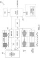
- FIG. 2 depicts a block diagram of an exemplary piezoelectric element functional self-test module, the module generating an excitation signal and determining a time-to-frequency conversion from a received piezoelectric element response signal during an interval immediately after excitation, the module producing a pass/fail result based on the conversion crossing a predetermined threshold.
- a gas sensor self-test configuration 200 includes a unit under test (UUT) 205. The UUT 205 is driven by an excitation signal 210. The excitation signal 210 is driven by an amplifier 215. In response to the excitation signal 210, the UUT 205 produces a response signal 220. The response signal 220 is coupled to a filter 225.
- the filter 225 may be an averaging filter.
- the averaging filter may be included in software in an advantageously straight forward implementation.
- the filter 225 may be a low-pass filter.
- the low-pass filter may be implemented cost-effectively in hardware.
- the filter 225 filters various electrical noise that may corrupt the response signal 220.
- the signal output from the filter 225 feeds an amplifier 230.
- the amplifier 230 produces a resulting amplified signal 235.
- the amplified signal 235 feeds an analog-to-digital converter (ADC) 240, which produces a digital output representative of a filtered and scaled time-domain value of the response signal 220.
- ADC analog-to-digital converter
- the signal processor 245 is part of a computing system which includes a (volatile) random-access memory (RAM) 250 and a non-volatile random-access memory NVRAM 255.
- the NVRAM 255 includes a program memory 260.
- the signal processor 245 may read from and write to the RAM 250.
- the signal processor 245 may read from the NVRAM 255 and the program memory 260.
- the signal processor 245 may read and execute preprogrammed instructions from the program memory 260.
- the signal processor 245 generates streaming data to a digital-to-analog converter (DAC) 265, the streaming data representing a scaled version of the excitation signal 210.
- the DAC 265 generates an analog waveform in response to the data values coming from the signal processor 245.
- the analog waveform out of the DAC 265 feeds the input to the amplifier 215.
- the excitation signal 210 is represented by an exemplary excitation waveform 210A.
- the excitation waveform 210A is directed by the signal processor 245, produced by the DAC 265 and scaled by the amplifier 215.
- the excitation waveform 210A is made up of two intervals T ON and T OFF , which repeat in an alternating fashion.
- the signal processor 245 may include an FFT code module 270.
- the signal processor 245 may execute the preprogrammed instructions in the FFT code module 270. This code execution may convert the digital output of the ADC 240 (during a time interval T OFF ) to frequency domain values.
- the signal processor 245 may produce a signal output 275 in response to the amplitude of the frequency domain values.
- a self-test module may include the signal processor 245, the RAM 250, the NVRAM 255 (including the program memory 260 and the FFT code module 270), the ADC 240, the DAC 265, the amplifiers 215, 235, the filter 225 and the UUT 205.
- the STM may include the excitation waveform 210A and the pass/fail signal output 275.
- a known good UUT 205 outputs a response signal, such as response signal 220 in response to the applied excitation waveform 210A.
- a response signal such as response signal 220 in response to the applied excitation waveform 210A.
- the response may resemble a waveform 235A.
- the waveform 235A couples through the ADC 240 to the signal processor 245.
- the signal processor 245 executing preprogrammed instructions from the FFT code module 270 converts the T OFF portion of the waveform 235A into a frequency domain conversion.
- the waveform 235A includes a damped ring-wave in the T OFF portion of the waveform 235A.
- the frequency domain response (within a predetermined natural frequency band) of the T OFF portion of the waveform 235A may be greater than a predetermined threshold, in the frequencies centered about the fundamental frequency of the ring-wave.
- the signal processor 245 may generate a PASS result to the signal output 275.
- the PASS result may correspond to a qualified (e.g., good, functional, acceptable) UUT 205.
- a known bad UUT 205 outputs a response signal, such as response signal 220, in response to the applied excitation waveform 210A.
- response signal 220 Once filtered through the filter 224 and amplified through the amplifier 230 the response may resemble a waveform 235B.
- the waveform 235B couples through the ADC 240 to the signal processor 245.
- the signal processor 245 executing preprogrammed instructions from the FFT code module 270 converts the T OFF portion of the waveform 235B into a frequency domain conversion.
- the waveform 235B includes a substantially zero signal in the T OFF portion of the waveform 235B.
- the frequency domain response (within a predetermined natural frequency band) of the T OFF portion of the waveform 235B may not contain frequency content greater than the predetermined threshold.
- the signal processor 245 may generate a FAIL result to the signal output 275.
- the FAIL result may correspond to a disqualified (e.g., bad, damaged, non-functional, unacceptable, defective) UUT 205.
- FIG. 3 depicts a block diagram of an exemplary piezoelectric element functional self-test module, the module generating an excitation signal and producing a time-to-frequency conversion from a received piezoelectric element response signal during an interval immediately after excitation, the module producing a pass/fail result based on the time-to-frequency conversion crossing a predetermined threshold.
- a piezoelectric element test setup 300 includes a piezoelectric element 305 under test. The piezoelectric element 305 is driven by an excitation signal 310 via the amplifier 215. In response to the excitation signal 310, the piezoelectric element 305 produces the response signal 220.
- the signal processor 245 directly generates a scaled version of the excitation signal 310.
- the signal processor 245 generates a burst square wave as depicted in the exemplary waveform 310A. With the exception of the square wave excitation signal and the generation thereof, the remaining functionality of FIG. 3 follows the description with reference to FIG. 2 .
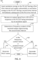
- FIG. 4 depicts a flowchart of an exemplary piezoelectric element functional self-test circuit module.
- a self-test module (STM) may be adapted to couple to an output port of a piezoelectric Unit Under Test (PZ-UUT).
- the STM may execute a self-test program 400 including preprogramed instruction beginning at step 405.
- the self-test program 400 injects excitation energy to the PZ-UUT during a first time-interval and supplies substantially no excitation energy to the PZ-UUT during a second time-interval immediately subsequent to the first interval. Execution continues to a step 410.
- the self-test program 400 receives an output signal from the PZ-UUT in response to the PZ-UUT being stimulated by an excitation signal. Execution continues to step 415. At step 415, the self-test program 400 determines, with the STCM, a frequency content of the received output signal during the second time-interval. In some examples, the self-test program 400 may produce an FFT from the received output signal during the second time-interval. Execution continues to step 420. At step 420, the self-test program 400 compares the frequency content at a predetermined comparison time during the second time-interval to a predetermined threshold amplitude.
- step 425 If the frequency content at a predetermined comparison time during the second time-interval is above a predetermined threshold amplitude, then execution proceeds to step 425, where the self-test program 400 generates a PASS result, and the self-test program 400 is exited. If the frequency content at a predetermined comparison time during the second time-interval is below a predetermined threshold amplitude, then execution jumps to step 430, where the self-test program 400 generates a FAULT (e.g., FAIL) result, and the self-test program 400 is exited.
- FAULT e.g., FAIL
- sine bursts may be directed by a processor, produced by a converter and driven by an amplifier.
- the test bursts may be injected into a piezoelectric gas sensor subassembly.
- the piezoelectric gas sensor subassembly may be configured to receive the sine bursts and capacitively couple them to a piezoelectric membrane within the piezoelectric gas sensor subassembly.
- a response from the output of the piezoelectric gas sensor subassembly may be sent to an ADC then captured by the processor.
- a ringing signal may damp out very slowly and may produce an FFT (within a predetermined natural frequency band) above a predetermined threshold.
- the ringing may damp out very rapidly producing an FFT (within a predetermined natural frequency band) below a predetermined threshold.
- the processor module may produce a PASS result for the FFT (within a predetermined natural frequency band) above the predetermined threshold and may produce a FAIL result for the FFT (within a predetermined natural frequency band) at or below the predetermined threshold.
- the pass/fail result may be a pass/fail indication.
- test method implementations may accommodate testing an ultrasonic sensor (e.g., a piezoelectric sensor) within a gas detection instrument (e.g., HLA 105), without instrument disassembly.
- the test may involve sending an input signal (e.g., burst of sinusoidal waves) to the ultrasonic sensor and evaluating the frequency response of the piezoelectric sensor in-between two bursts of the input signal. If the noise-reduced response includes a signal (e.g., ringing signal) in-between two bursts, then the frequency response may exceed a predetermined threshold (within a predetermined natural frequency band).
- the tester may determine a passing result in response to the frequency response exceeding the predetermined threshold (within a predetermined natural frequency band).
- the passing result may indicate that the ultrasonic sensor is operating efficiently. Accordingly, the tester may determine a failing result in response to the frequency response remaining below the predetermined threshold (within a predetermined natural frequency band). In some examples, the failing result may indicate that the ultrasonic sensor is operating inefficiently.
- the signal processor 245, the RAM 250, the NVRAM 255, the ADC 240 and/or the DAC 265 may be implemented in existing hardware circuits.
- an end-product e.g., HLA 105
- the various hardware may include one or more processors, RAMs, NVRAMs, ADCs and/or DACs.
- the end-product may also implement a self-test function. The implementation of the self-test function may use one or more of the various hardware described, leveraging those existing various hardware resources to perform its function.
- a microcontroller on an existing gas detector instrument may be additionally programmed to perform the excitation signal generation, the FFT function, the threshold detection and the pass/fail output functions.
- a detected failure may display a warning message on the end-product display.
- a detected failure may display a warning light.
- the warning light may be advantageous in various dark environments.
- a detected failure may provide haptic (e.g., vibrational) feedback.
- the vibrational feedback may be advantageous in audibly noisy environments, or in environments where light and sound may be objectionable (e.g., movie theatres, churches).
- a detected failure may provide an audible alert.
- the audible alert may be advantageous in situations where the end-product is not in sight or not a constant visual focus (e.g., in a pocket, around a neck or wrist).
- Some aspects of embodiments may be implemented as a computer system.
- various implementations may include digital and/or analog circuitry, computer hardware, firmware, software, or combinations thereof.
- Apparatus elements can be implemented in a computer program product tangibly embodied in an information carrier, e.g., in a machine-readable storage device, for execution by a programmable processor; and methods can be performed by a programmable processor executing a program of instructions to perform functions of various embodiments by operating on input data and generating an output.
- Some embodiments may be implemented advantageously in one or more computer programs that are executable on a programmable system including at least one programmable processor coupled to receive data and instructions from, and to transmit data and instructions to, a data storage system, at least one input device, and/or at least one output device.
- a computer program is a set of instructions that can be used, directly or indirectly, in a computer to perform a certain activity or bring about a certain result.
- a computer program can be written in any form of programming language, including compiled or interpreted languages, and it can be deployed in any form, including as a stand-alone program or as a module, component, subroutine, or other unit suitable for use in a computing environment.
- Suitable processors for the execution of a program of instructions include, by way of example and not limitation, both general and special purpose microprocessors, which may include a single processor or one of multiple processors of any kind of computer. Generally, a processor will receive instructions and data from a read-only memory or a random-access memory or both.
- the essential elements of a computer are a processor for executing instructions and one or more memories for storing instructions and data.
- Storage devices suitable for tangibly embodying computer program instructions and data include all forms of non-volatile memory, including, by way of example, semiconductor memory devices, such as EPROM, EEPROM, and flash memory devices; magnetic disks, such as internal hard disks and removable disks; magneto-optical disks; and, CD-ROM and DVD-ROM disks.
- the processor and the memory can be supplemented by, or incorporated in, ASICs (application-specific integrated circuits).
- ASICs application-specific integrated circuits
- the processor and the member can be supplemented by, or incorporated in hardware programmable devices, such as FPGAs, for example.
- one or more user-interface features may be custom configured to perform specific functions.
- An exemplary embodiment may be implemented in a computer system that includes a graphical user interface and/or an Internet browser.
- some implementations may be implemented on a computer having a display device, such as an LCD (liquid crystal display) monitor for displaying information to the user, a keyboard, and a pointing device, such as a mouse or a trackball by which the user can provide input to the computer.
- a display device such as an LCD (liquid crystal display) monitor for displaying information to the user
- a keyboard such as a keyboard
- a pointing device such as a mouse or a trackball by which the user can provide input to the computer.
- the system may communicate using suitable communication methods, equipment, and techniques.
- the system may communicate with compatible devices (e.g., devices capable of transferring data to and/or from the system) using point-to-point communication in which a message is transported directly from a source to a first receiver over a dedicated physical link (e.g., fiber optic link, point-to-point wiring, daisy-chain).
- the components of the system may exchange information by any form or medium of analog or digital data communication, including packet-based messages on a communication network.
- Examples of communication networks include, e.g., a LAN (local area network), a WAN (wide area network), MAN (metropolitan area network), wireless and/or optical networks, and the computers and networks forming the Internet.
- a computer system may include non-transitory memory.
- the memory may be connected to the one or more processors may be configured for encoding data and computer readable instructions, including processor executable program instructions.
- the data and computer readable instructions may be accessible to the one or more processors.
- the processor executable program instructions when executed by the one or more processors, may cause the one or more processors to perform various operations.
- the computer system may include Internet of Things (IoT) devices.
- IoT devices may include objects embedded with electronics, software, sensors, actuators, and network connectivity which enable these objects to collect and exchange data.
- IoT devices may be in-use with wired or wireless devices by sending data through an interface to another device. IoT devices may collect useful data and then autonomously flow the data between other devices.
- a test method may include: (1) producing a digital stream representing an excitation function characterized by a sine wave gated with off times during an interval T 2 , (2) receiving data from an ADC, representing the UUT response to the excitation function, (3) determining an average amplitude of a natural frequency from the received data during an interval T 2 , (4) comparing the average amplitude result to a predetermined threshold during the interval T 2 , (5) determining a fail result when the average amplitude result is below the predetermined threshold, and (6) determining a pass result when the average amplitude result is above the predetermined threshold.
- a test method for testing a piezoelectric device may include (1) providing a self-test circuit module (STCM) adapted to couple to an output port of a piezoelectric Unit Under Test (PZ-UUT), (2) receiving an output signal from the PZ-UUT in response to the PZ-UUT being stimulated by an excitation signal, (3) determining, with the STCM, a frequency content of the received output signal during the second time interval, (4) comparing, with the STCM, the determined frequency content at a predetermined comparison time during the second time interval to a predetermined threshold amplitude. If the determined frequency content is less than the predetermined threshold amplitude, then the test method may generate a status signal indicative of a fault in the PZ-UUT.
- STCM self-test circuit module
- PZ-UUT piezoelectric Unit Under Test
- the STCM may include a processor configured to control the application of the excitation signal to the PZ-UUT during the first time-interval.
- the processor may be configured to disable the supply of the excitation signal to the PZ-UUT during the second time-interval.
- the processor may be configured to cause the generation of the excitation signal using a digital-to-analog converter (DAC).
- DAC digital-to-analog converter
- the test method for testing a piezoelectric device may include an amplifier circuit coupled to the DAC.
- the amplifier may be configured to amplify an output of the DAC to generate the injected excitation energy to the PZ-UUT.
- the received output signal from the PZ-UUT during the second time-interval may include a non-oscillating natural response waveform.
- the predetermined comparison time may be less than about 100, 90, 80, 70, 60, 50, 40 ,30, 20, or less than about 10 periods of the periodic excitation signal after the start of the second time-interval.
- the excitation signal may be periodic during the first time-interval.
- the frequency of the excitation signal may be defined by an inverse of a period of the periodic excitation signal.
- the inverse of the period of the periodic excitation signal may be within one percent of a natural response frequency of the PZ-UUT.
- the test method for testing a piezoelectric device may include providing an averaging filter.
- the averaging filter may be coupled between the PZ-UUT and the STCM.
- the averaging filter may be configured to filter the received output signal.
- a test apparatus for testing a piezoelectric device may include a self-test circuit module (STCM) adapted to couple to an output port of a piezoelectric Unit Under Test (PZ-UUT).
- the test apparatus may also include a data store operatively coupled to the STCM and may contain a program of instructions that, when executed by the STCM, may cause the STCM to perform operations to evaluate the operational integrity of the PZ-UUT.
- the operations may include: (1) receiving an output signal from the PZ-UUT in response to the PZ-UUT being stimulated by an excitation signal, (2) determining, with the STCM, a frequency content amplitude of the received output signal during the second time interval, (3) comparing, with the STCM, the determined frequency content amplitude at a predetermined comparison time during the second time interval to a predetermined threshold amplitude. If the determined frequency content is less than the predetermined threshold amplitude, then the test method may generate a status signal indicative of a fault in the PZ-UUT.
- the STCM may include a processor operable to execute the program of instructions.
- a test apparatus for testing a piezoelectric device may include a self-testing module (STM) and a piezoelectric Unit Under Test (PZ-UUT).
- the test apparatus may also include a data store operatively coupled to the STM and may contain a program of instructions that, when executed by the STM, may cause the STM to perform operations to evaluate the operational integrity of the PZ-UUT.
- the operations may include: (1) receiving an output signal from the PZ-UUT in response to the PZ-UUT being stimulated by an excitation signal, (2) determining, with the STM, a frequency content amplitude of the received output signal during the second time interval, (3) comparing, with the STM, the determined frequency content amplitude at a predetermined comparison time during the second time interval to a predetermined threshold amplitude. If the determined frequency content is less than the predetermined threshold amplitude, then the test method may generate a status signal indicative of a fault in the PZ-UUT.
- the STM may execute the program of instructions.
- the operations may include controlling the application of the excitation signal to the PZ-UUT during the first time-interval.
Landscapes
- Physics & Mathematics (AREA)
- General Physics & Mathematics (AREA)
- Engineering & Computer Science (AREA)
- General Engineering & Computer Science (AREA)
- Investigating Or Analyzing Materials By The Use Of Ultrasonic Waves (AREA)
- Measurement Of Mechanical Vibrations Or Ultrasonic Waves (AREA)
- Testing Of Devices, Machine Parts, Or Other Structures Thereof (AREA)
- Investigating Or Analyzing Materials By The Use Of Electric Means (AREA)
Priority Applications (1)
| Application Number | Priority Date | Filing Date | Title |
|---|---|---|---|
| EP24187210.0A EP4421497A3 (de) | 2018-02-12 | 2018-02-12 | Funktioneller selbsttest für ein in einem endprodukt eingesetztes piezoelektrisches element |
Applications Claiming Priority (2)
| Application Number | Priority Date | Filing Date | Title |
|---|---|---|---|
| EP18156383.4A EP3524946B1 (de) | 2018-02-12 | 2018-02-12 | Funktioneller selbsttest für ein piezoelektrisches, in einem endprodukt eingesetztes element |
| EP24187210.0A EP4421497A3 (de) | 2018-02-12 | 2018-02-12 | Funktioneller selbsttest für ein in einem endprodukt eingesetztes piezoelektrisches element |
Related Parent Applications (1)
| Application Number | Title | Priority Date | Filing Date |
|---|---|---|---|
| EP18156383.4A Division EP3524946B1 (de) | 2018-02-12 | 2018-02-12 | Funktioneller selbsttest für ein piezoelektrisches, in einem endprodukt eingesetztes element |
Publications (2)
| Publication Number | Publication Date |
|---|---|
| EP4421497A2 true EP4421497A2 (de) | 2024-08-28 |
| EP4421497A3 EP4421497A3 (de) | 2024-12-11 |
Family
ID=61226384
Family Applications (2)
| Application Number | Title | Priority Date | Filing Date |
|---|---|---|---|
| EP18156383.4A Active EP3524946B1 (de) | 2018-02-12 | 2018-02-12 | Funktioneller selbsttest für ein piezoelektrisches, in einem endprodukt eingesetztes element |
| EP24187210.0A Pending EP4421497A3 (de) | 2018-02-12 | 2018-02-12 | Funktioneller selbsttest für ein in einem endprodukt eingesetztes piezoelektrisches element |
Family Applications Before (1)
| Application Number | Title | Priority Date | Filing Date |
|---|---|---|---|
| EP18156383.4A Active EP3524946B1 (de) | 2018-02-12 | 2018-02-12 | Funktioneller selbsttest für ein piezoelektrisches, in einem endprodukt eingesetztes element |
Country Status (2)
| Country | Link |
|---|---|
| US (1) | US10996254B2 (de) |
| EP (2) | EP3524946B1 (de) |
Families Citing this family (5)
| Publication number | Priority date | Publication date | Assignee | Title |
|---|---|---|---|---|
| KR102141889B1 (ko) * | 2019-02-19 | 2020-08-06 | 주식회사 동운아나텍 | 적응적 햅틱 신호 발생 장치 및 방법 |
| EP4007943B1 (de) * | 2019-09-25 | 2025-06-04 | Rosemount Inc. | Überwachung des zustands eines piezoelektrischen wandlers |
| DE102019129177A1 (de) * | 2019-10-29 | 2021-04-29 | Krohne Messtechnik Gmbh | Wirbeldurchflussmessgerät und Verfahren zum Betreiben eines Wirbeldurchflussmessgeräts |
| US20240418550A1 (en) * | 2023-06-14 | 2024-12-19 | Antonio Davido Trigiani | Performance monitor for ultrasonic transducer |
| CN117388673A (zh) * | 2023-12-11 | 2024-01-12 | 珠海芯业测控有限公司 | Ate设备及其芯片测试方法、电子设备、存储介质 |
Family Cites Families (9)
| Publication number | Priority date | Publication date | Assignee | Title |
|---|---|---|---|---|
| GB1369435A (en) * | 1970-10-30 | 1974-10-09 | Secr Defence | Piezoelectric transducer testing system |
| US5447051A (en) | 1993-08-05 | 1995-09-05 | Hewlett-Packard Company | Method and apparatus for testing a piezoelectric force sensor |
| EP0715722B1 (de) * | 1993-08-24 | 1998-06-03 | A/S BRÜEL & KJAER | Vorrichtung zur entdeckung fehlerhaften funktionierens eines beschleunigungsmessaufnehmers |
| US6111335A (en) * | 1993-12-28 | 2000-08-29 | Beniamin Acatrinei | Piezoelectric interface analyzer |
| IT1299401B1 (it) * | 1998-03-27 | 2000-03-16 | Optikon 2000 Spa | Procedimento di ottimizzazione del pilotaggio di un attuatore piezoelettrico, in particolare per dispositivi facoemulsificatori, |
| US7042228B2 (en) * | 2001-04-27 | 2006-05-09 | Oceana Sensor Technologies, Inc. | Transducer in-situ testing apparatus and method |
| US6556028B1 (en) * | 2001-05-07 | 2003-04-29 | Storage Test Solutions, Inc. | Method and apparatus for detecting defects in piezoelectric actuators |
| US8401820B2 (en) * | 2008-10-03 | 2013-03-19 | United States Of America As Represented By The Administrator Of The National Aeronautics And Space Administration | In situ health monitoring of piezoelectric sensors |
| US12000886B2 (en) * | 2017-12-04 | 2024-06-04 | Aktiebolaget Skf | Self-test circuit and a method of checking the integrity of a signal through a signal path |
-
2018
- 2018-02-12 EP EP18156383.4A patent/EP3524946B1/de active Active
- 2018-02-12 EP EP24187210.0A patent/EP4421497A3/de active Pending
-
2019
- 2019-02-07 US US16/269,788 patent/US10996254B2/en active Active
Also Published As
| Publication number | Publication date |
|---|---|
| US10996254B2 (en) | 2021-05-04 |
| US20190250200A1 (en) | 2019-08-15 |
| EP3524946A1 (de) | 2019-08-14 |
| EP4421497A3 (de) | 2024-12-11 |
| EP3524946B1 (de) | 2024-07-10 |
Similar Documents
| Publication | Publication Date | Title |
|---|---|---|
| US10996254B2 (en) | Self-test for a piezoelectric device | |
| US12178620B2 (en) | Robust alarm system | |
| CN101925828B (zh) | 测试用于串联电弧检测的afci设备的方法和装置 | |
| JP6444298B2 (ja) | 音響トランスデューサを確認する方法及びシステム | |
| CN106104246B (zh) | 超声气体泄露检测器和测试方法 | |
| WO2005077029A3 (en) | Transducer in-situ testing apparatus and method | |
| CN104424731B (zh) | 无声地监控警报发声器的装置和方法 | |
| KR102696240B1 (ko) | 자체-테스팅 측정 시스템 및 자체-테스팅 측정 시스템을 작동시키기 위한 방법 | |
| MX392550B (es) | Panel para la monitorización audible de componentes eléctricos y detección de fallas eléctricas. | |
| JP6853133B2 (ja) | 音響校正器 | |
| US7353708B2 (en) | Ultrasonic generator system | |
| CN103027688B (zh) | 一种耳声发射仿真测试系统 | |
| US20210250675A1 (en) | In-ear detection utilizing earbud feedback microphone | |
| CN115762180B (zh) | 一种自建磁场的停车检测系统及方法 | |
| WO2014071537A1 (zh) | 一种耳声发射仿真测试系统 | |
| CN222091682U (zh) | 一种脉冲振荡模块 | |
| CN110837013A (zh) | 一种利用稀疏字典表示的变压器状态振声检测信号重构方法和系统 | |
| JP2020170883A (ja) | 非常放送装置 | |
| RU95101389A (ru) | Способ поверки ультразвуковых эхо-импульсных приборов и устройство для его осуществления | |
| JPH03229150A (ja) | 炎の検出装置 | |
| JP2008083623A (ja) | 音声信号発生装置 | |
| KR960018534A (ko) | 초음파 장치의 에러 진단 방법 및 그 장치 |
Legal Events
| Date | Code | Title | Description |
|---|---|---|---|
| PUAI | Public reference made under article 153(3) epc to a published international application that has entered the european phase |
Free format text: ORIGINAL CODE: 0009012 |
|
| STAA | Information on the status of an ep patent application or granted ep patent |
Free format text: STATUS: THE APPLICATION HAS BEEN PUBLISHED |
|
| AC | Divisional application: reference to earlier application |
Ref document number: 3524946 Country of ref document: EP Kind code of ref document: P |
|
| AK | Designated contracting states |
Kind code of ref document: A2 Designated state(s): AL AT BE BG CH CY CZ DE DK EE ES FI FR GB GR HR HU IE IS IT LI LT LU LV MC MK MT NL NO PL PT RO RS SE SI SK SM TR |
|
| REG | Reference to a national code |
Ref country code: DE Ref legal event code: R079 Free format text: PREVIOUS MAIN CLASS: G01P0021000000 Ipc: G01H0003000000 |
|
| PUAL | Search report despatched |
Free format text: ORIGINAL CODE: 0009013 |
|
| AK | Designated contracting states |
Kind code of ref document: A3 Designated state(s): AL AT BE BG CH CY CZ DE DK EE ES FI FR GB GR HR HU IE IS IT LI LT LU LV MC MK MT NL NO PL PT RO RS SE SI SK SM TR |
|
| RIC1 | Information provided on ipc code assigned before grant |
Ipc: G01H 11/08 20060101ALN20241106BHEP Ipc: G01R 31/01 20200101ALI20241106BHEP Ipc: G01R 31/28 20060101ALI20241106BHEP Ipc: G01R 29/22 20060101ALI20241106BHEP Ipc: G01D 21/00 20060101ALI20241106BHEP Ipc: G01D 18/00 20060101ALI20241106BHEP Ipc: G01P 21/00 20060101ALI20241106BHEP Ipc: G01H 3/00 20060101AFI20241106BHEP |
|
| STAA | Information on the status of an ep patent application or granted ep patent |
Free format text: STATUS: REQUEST FOR EXAMINATION WAS MADE |
|
| 17P | Request for examination filed |
Effective date: 20250610 |