EP4421492A1 - Automated analysis system, and conveying method - Google Patents
Automated analysis system, and conveying method Download PDFInfo
- Publication number
- EP4421492A1 EP4421492A1 EP22883438.8A EP22883438A EP4421492A1 EP 4421492 A1 EP4421492 A1 EP 4421492A1 EP 22883438 A EP22883438 A EP 22883438A EP 4421492 A1 EP4421492 A1 EP 4421492A1
- Authority
- EP
- European Patent Office
- Prior art keywords
- vessel
- conveying
- loading
- automatic analyzer
- automatic
- Prior art date
- Legal status (The legal status is an assumption and is not a legal conclusion. Google has not performed a legal analysis and makes no representation as to the accuracy of the status listed.)
- Pending
Links
Images




Classifications
-
- G—PHYSICS
- G01—MEASURING; TESTING
- G01N—INVESTIGATING OR ANALYSING MATERIALS BY DETERMINING THEIR CHEMICAL OR PHYSICAL PROPERTIES
- G01N35/00—Automatic analysis not limited to methods or materials provided for in any single one of groups G01N1/00 - G01N33/00; Handling materials therefor
- G01N35/02—Automatic analysis not limited to methods or materials provided for in any single one of groups G01N1/00 - G01N33/00; Handling materials therefor using a plurality of sample containers moved by a conveyor system past one or more treatment or analysis stations
- G01N35/04—Details of the conveyor system
-
- G—PHYSICS
- G01—MEASURING; TESTING
- G01N—INVESTIGATING OR ANALYSING MATERIALS BY DETERMINING THEIR CHEMICAL OR PHYSICAL PROPERTIES
- G01N35/00—Automatic analysis not limited to methods or materials provided for in any single one of groups G01N1/00 - G01N33/00; Handling materials therefor
- G01N35/02—Automatic analysis not limited to methods or materials provided for in any single one of groups G01N1/00 - G01N33/00; Handling materials therefor using a plurality of sample containers moved by a conveyor system past one or more treatment or analysis stations
- G01N35/04—Details of the conveyor system
- G01N2035/0401—Sample carriers, cuvettes or reaction vessels
- G01N2035/0406—Individual bottles or tubes
-
- G—PHYSICS
- G01—MEASURING; TESTING
- G01N—INVESTIGATING OR ANALYSING MATERIALS BY DETERMINING THEIR CHEMICAL OR PHYSICAL PROPERTIES
- G01N35/00—Automatic analysis not limited to methods or materials provided for in any single one of groups G01N1/00 - G01N33/00; Handling materials therefor
- G01N35/02—Automatic analysis not limited to methods or materials provided for in any single one of groups G01N1/00 - G01N33/00; Handling materials therefor using a plurality of sample containers moved by a conveyor system past one or more treatment or analysis stations
- G01N35/04—Details of the conveyor system
- G01N2035/046—General conveyor features
- G01N2035/0465—Loading or unloading the conveyor
-
- G—PHYSICS
- G01—MEASURING; TESTING
- G01N—INVESTIGATING OR ANALYSING MATERIALS BY DETERMINING THEIR CHEMICAL OR PHYSICAL PROPERTIES
- G01N35/00—Automatic analysis not limited to methods or materials provided for in any single one of groups G01N1/00 - G01N33/00; Handling materials therefor
- G01N35/02—Automatic analysis not limited to methods or materials provided for in any single one of groups G01N1/00 - G01N33/00; Handling materials therefor using a plurality of sample containers moved by a conveyor system past one or more treatment or analysis stations
- G01N35/04—Details of the conveyor system
- G01N2035/0474—Details of actuating means for conveyors or pipettes
- G01N2035/0491—Position sensing, encoding; closed-loop control
- G01N2035/0494—Detecting or compensating piositioning errors
-
- G—PHYSICS
- G01—MEASURING; TESTING
- G01N—INVESTIGATING OR ANALYSING MATERIALS BY DETERMINING THEIR CHEMICAL OR PHYSICAL PROPERTIES
- G01N35/00—Automatic analysis not limited to methods or materials provided for in any single one of groups G01N1/00 - G01N33/00; Handling materials therefor
- G01N35/0099—Automatic analysis not limited to methods or materials provided for in any single one of groups G01N1/00 - G01N33/00; Handling materials therefor comprising robots or similar manipulators
Definitions
- the present invention relates to an automatic analyzing system and a conveying method.
- Patent Literature 1 discloses a technique for conveying the reagent or the sample by a self-traveling conveying robot.
- Patent Literature 1 Japanese Unexamined Patent Application Publication No. 2001-278409
- Patent Literature 1 discloses the technique for conveying the reagent or the sample by the self-traveling robot and the like, and since the teaching operation for creating the operation program of the robot arm that has six degrees of freedom or more for automating the loading of the reagent or the sample into the automatic analyzer is troublesome, the introduction of the robot arm requires much time and effort. In addition, when the conveying robot is introduced into a facility in which the automatic analyzer is already installed, the re-examination of the layout of the automatic analyzer is required depending on the case, so that there is a problem that it takes much time and cost.
- an object of the present invention is to provide an automatic analyzing system that freely sets a vertical or horizontal dimension with respect to a traveling surface and has no influence on the layout of a device.
- An automatic analyzing system comprises: an automatic analyzer that analyzes a sample; a conveying portion that conveys a vessel that accommodates a liquid; a loading portion that receives the vessel from the conveying portion and loads the vessel into the automatic analyzer; and a correction portion that performs, in order to be capable of allowing the conveying portion to deliver the vessel to the loading portion, position correction between the conveying portion and the loading portion.
- the correction portion includes: a hole provided in the loading portion and for constraining rotation motion; one rotation shaft or more; an extension and contraction portion that is provided in the loading portion and generates tension that holds a rotation angle constant; and a member that is provided in the conveying portion and constrains the rotation motion.
- an automatic analyzing system that freely sets a vertical or horizontal dimension with respect to a traveling surface and has no influence on the layout of a device.
- a first embodiment is an embodiment of an automatic analyzing system that achieves the translational driving of the X, Y, and Z axes of the robot arm and the rotational driving of the roll, pitch, and yaw axis by different mechanisms, and drives the respective mechanisms on the basis of sensor information, or drives the respective mechanisms by physical position correction, thereby eliminating teaching.
- this embodiment is an embodiment of the automatic analyzing system including an automatic analyzer that analyzes a sample, a conveying portion that conveys a vessel that accommodates the sample, a loading portion that receives the vessel from the conveying portion and loads the vessel into the automatic analyzer, and a correction portion that performs position correction between the conveying portion and the loading portion in order for the conveying portion to be able to deliver the vessel to the loading portion, in which the correction portion includes a hole provided in the loading portion and for constraining rotation motion, one rotation shaft or more, an extension and contraction portion that is provided in the loading portion and generates tension that holds a rotation angle constant, and a member that is provided in the conveying portion and constrains the rotation motion, in which by inserting the end of the member into the hole, the position correction between the conveying portion and the loading portion is performed, and in which by the rotation motion about the rotation shaft, the vessel is delivered from the conveying portion to a loading opening, and a conveying method of the same.
- FIG. 1 is a diagram illustrating the configuration of the conveying portion (also referred to as an autonomous moving cart or a robot) that conveys the vessel that accommodates the liquid of the automatic analyzing system.
- a conveying portion 101 includes: a vertical driving mechanism 102 and a horizontal driving mechanism 108 that drive a vertical transmission type sensor 103 and a hand portion 105; a vessel 106 that accommodates the liquid; a vessel storing portion 107 that stores the vessel 106, and the like.
- the reference numeral 104 denotes transmission light of vertical transmission type sensor.
- FIG. 2 is a diagram illustrating the hand portion of the automatic analyzing system.
- the hand portion 105 includes a horizontal transmission type sensor 109, a positioning pin 111, a grasping hand 112, a grasping hand driving mechanism 113, and a positioning pin driving mechanism 114.
- the transmission light of vertical transmission type sensor 104 and transmission light of horizontal transmission type sensor 110 illustrated in FIGS. 1 and 2 are blocked according to the position of the hand portion 105, as appropriate, and can generate the sensor information.
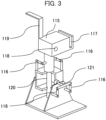
- FIG. 3 is a diagram illustrating the rear surface of a correction portion 115
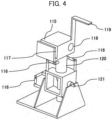
- FIG. 4 is a diagram illustrating the front surface of the correction portion 115
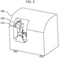
- FIG. 5 is a diagram illustrating a state where the correction portion is installed in the automatic analyzing system.
- the correction portion 115 illustrated in FIGS. 3 and 4 includes a loading portion 117 for the vessel 106, a positioning pin hole 118, and a detection plate 119, and as illustrated in FIGS. 10 , the correction portion 115 is pulled by tension springs 116, and is rotatable around a roll axis rotation shaft 120 and a yaw axis rotation shaft 121.
- the correction portion 115 is installed in a loading opening 123 for the vessel 106 that is the loading portion of an automatic analyzer 122.
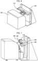
- FIG. 6 is a diagram illustrating a state where the conveying portion 101 is installed on the front surface of the automatic analyzer 122. As illustrated in the drawing, at the time of installing the correction portion 115, the conveying portion 101 conveys the correction portion 115 to the liquid vessel loading opening of the automatic analyzer 122. Then, as illustrated in FIGS. 7 , 8 , and 9 , the correction portion 115 is installed at predetermined positions.
- FIG. 7 is a diagram illustrating the arrangement position of the jack at the time of installing the correction portion 115
- FIG. 8 is a diagram illustrating the lift function of the automatic analyzing system
- FIG. 9 is a diagram illustrating a state after the removal of the handle after the correction portion 115 is conveyed to the predetermined position.
- FIGS. 7 and 8 illustrate a state before the lifting of the vertical driving mechanism and a state after the lifting of the vertical driving mechanism, respectively.
- FIGS. 10(A) and 10(B) illustrate schematic diagrams of the correction portion.
- the correction portion 115 is rotatable about the roll axis rotation shaft 120.
- tension is applied to the correction portion 115 by the tension springs 116 so as to be positioned at the center at all times.
- FIG. 11 when the correction portion 115 is rotated counterclockwise by an external force, the correction portion 115 is rotated clockwise by spring reaction force 125 (126) caused about roll axis rotation shaft by the tension of the tension springs 116, and is returned to the original angle.
- FIG. 12 illustrates a schematic diagram of the conveying portion 101.
- the positioning pin 111 and the hand 112 capable of grasping the vessel 106 are attached to the ends of the grasping hand driving mechanism 113 and the positioning pin driving mechanism 114 that are provided to the conveying portion 101, respectively.
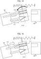
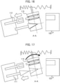
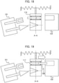
- FIGS. 13 to 19 illustrate first to seventh stages of a liquid vessel loading flow.
- the drawings are drawings when the automatic analyzer 122 is seen from directly above.
- the conveying portion 101 moves to near the correction portion 115 by linear motion, but cannot load the vessel 106 as-is since the angles are different.
- the positioning pin 111 that is attached to the positioning pin driving mechanism 114 that is provided to the conveying portion 101 is inserted into the positioning pin hole 118 of the correction portion 115.
- the positioning pin 111 is inserted into the hole of the correction portion.
- the correction portion 115 is rotatable and the positioning pin 111 is in wedge shape or conical shape, the correction portion 115 is rotated at the same angle as the conveying portion 101.
- the hand 112 is extended to deliver the vessel 106 to the loading portion 117, and the hand is returned. Since in this state, the angles of the correction portion and the automatic analyzer are different, the vessel cannot be delivered to the automatic analyzer.
- the loading portion 117 is made to have the same angle as the automatic analyzer 122, and the vessel 106 can be delivered from the loading portion 117 to the automatic analyzer 122.
- the correction portion 115 is rotatable, and the end of the positioning pin 111 is in wedge shape or conical shape, as illustrated in FIG. 14 , the correction portion 115 is rotated at the same angle as the conveying portion 101.
- the hand 112 is extended to deliver the vessel 106 to the loading portion 117, and as illustrated in FIG. 16 , the hand 112 is returned. Since in this state, the angles of the correction portion 115 and the automatic analyzer 122 are different, the vessel 106 cannot be delivered to the automatic analyzer 122.
- the correction portion 115 is rotated by the tension of the tension springs 116 so as to be returned to the original position, and as illustrated in FIG. 18 , the loading portion 117 is made to have the same angle as the automatic analyzer 122.
- the vessel 106 can be delivered from the loading portion 117 to the loading opening 123 of the automatic analyzer 122.
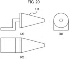
- FIGS. 20(A), 20(B), and 20(C) are three-view diagrams illustrating the shape of the positioning pin 111.
- FIGS. 20(A), 20(B), and 20(C) illustrate the side view, front view, and top view of the pin 111.
- FIG. 21 is a diagram illustrating the automatic analyzer and the conveying portion. The respective components of this system can be operated by the control of a control device 126 (127) that is provided to the conveying portion 101 and includes a central processing unit (CPU) and the like.
- a control device 126 (127) that is provided to the conveying portion 101 and includes a central processing unit (CPU) and the like.
- CPU central processing unit
- FIG. 22 is a diagram illustrating the overall configuration of the automatic analyzing system.
- the automatic analyzing system includes: the automatic analyzer 122 that includes a vessel storing portion (for example, a reagent disk) 220 that stores a plurality of vessels 106 (for example, reagent vessels); an outside storage cabinet 221 that is provided in the outside of the automatic analyzer 122 and stores the plurality of vessels 106; the conveying portion 101 that conveys the vessel 106 between the outside storage cabinet 221 and the automatic analyzer 122; a conveying mechanism for vessel storing portion (a first conveying mechanism) 222 that performs the delivering of the vessel 106 via an arm 222a between the automatic analyzer 122 and the conveying portion 101; a conveying mechanism for outside storage cabinet (a second conveying mechanism) 223 that performs the delivering of the vessel 106 via an arm 223a between the outside storage cabinet 221 and the conveying portion 101; and a display portion 224 that displays various information with
- the first conveying mechanism 222 is fixed to the automatic analyzer 122, and is set so as to be able to precisely insert the vessel 106 from the arm 222a into the loading opening 123 (for example, a reagent slot) of the automatic analyzer 122. This is because when the insertion of the vessel 106 into the loading opening 123 is displaced even slightly, the normal installation into the vessel storing portion 220 is not enabled, thereby inversely affecting the analysis. On the other hand, since the conveying portion 101 and the first conveying mechanism 222 are replacing operation mechanisms, they can have relative tolerance for the position relationship between them.
- the second conveying mechanism 223 be also fixed to the outside storage cabinet 221.
- novel design according to the conveying portion 101 may be enabled. Therefore, when the design is enabled, position accuracy between the second conveying mechanism 223 and the outside storage cabinet 221 is not required to be higher than position accuracy between the second conveying mechanism 223 and the conveying portion 101.
- the second embodiment separates the correction portion 115 and the mechanism that delivers the vessel. That is, the conveying portion 101 that has moved from the outside storage cabinet 221 moves to the front of the automatic analyzer 122, uses the correction portion 115 to correct the position with respect to the automatic analyzer 122, and uses the first conveying mechanism 222 to deliver the vessel 106 to the automatic analyzer 122.
- the conveying portion 101 that has moved from the automatic analyzer 122 moves to the front of the outside storage cabinet 221, uses the correction portion 115 to correct the position with respect to the outside storage cabinet 221, and uses the second conveying mechanism 223 to deliver the vessel 106 to the outside storage cabinet 221.
- the conveying portion 101 may include an expansion storge cabinet that stores the vessel 106 that cannot be stored only by the vessel storing portion 220. That is, the first conveying mechanism and the conveying portion 101 can be operated like the expansion storage cabinet.
- the storage cabinet that keeps the vessel 106 cool is mounted on the upper portion of the conveying portion 101
- the automatic analyzer 122 manages management information 225 also including the vessel 106 on the conveying portion 101
- the first conveying mechanism and the conveying portion 101 are in a state of being able to be operated like the expansion storge cabinet in which the maximum number of vessels stored in the automatic analyzer 122 is increased.
- the conveying portion 101 can store the plurality of vessels 106 at all times, and can also supply the vessel 106 from the expansion storage cabinet to the vessel storing portion 220, as needed.
- the physical arrangement place of the vessel 106 in which the vessel 106 is physically stored in the outside of the vessel storing portion 220 and appears to be virtually stored in the inside of the expansion storage cabinet is not limited to be on the conveying portion 101.
- the vessel 106 may be removable from the automatic analyzer 122, or may be distributably arranged at the appropriate position in the automatic analyzing system.
- all the reagent vessels may be displayed to the user so as to be stored in the same virtual space. That is, the physical arrangement place and the virtual arrangement place of the vessel 106 are associated with each other to be stored, and the physical arrangement place is converted to the virtual arrangement place to be displayed on the display portion 224.
- the user is required to discriminate whether the vessel 106 is disposed in the inside of the automatic analyzer 122 and is in a state of being usable for the analysis or the vessel 106 is disposed in the outside of the automatic analyzer 122 and is in a state of being non-usable for the analysis. Accordingly, information that indicates whether the target vessel 106 is in the inside or outside of the automatic analyzer 122 may be provided to the display portion 224.
- the automatic analyzer 122 transmits and receives the management information 225 to and from the conveying portion 101 and the outside storage cabinet 221 (when the expansion storage cabinet is disposed in the outside of the conveying portion 101, the automatic analyzer 122 transmits and receives the management information 225 also to and from the expansion storage cabinet).
- the management information 225 is information for managing the liquid (for example, a reagent) stored in the vessel storing portion 220, the conveying portion 101, the outside storage cabinet 221, and/or the expansion storage cabinet.
- the management information 225 is transmitted and received among the automatic analyzer 122, the outside storage cabinet 221, and the conveying portion 101, so that the vessel 106 necessary for the analysis can be conveyed to the appropriate position at the appropriate timing.
- management information 225 may be stored in any one of the storage device included in the automatic analyzer 122, the storage device included in the conveying portion 101, the storage device included in the different mechanism, and the like.
- control portion that performs the control related to the transmission and reception of the management information 225 may also be installed in any place.
Landscapes
- Physics & Mathematics (AREA)
- Health & Medical Sciences (AREA)
- Life Sciences & Earth Sciences (AREA)
- Chemical & Material Sciences (AREA)
- Analytical Chemistry (AREA)
- Biochemistry (AREA)
- General Health & Medical Sciences (AREA)
- General Physics & Mathematics (AREA)
- Immunology (AREA)
- Pathology (AREA)
- Automatic Analysis And Handling Materials Therefor (AREA)
Abstract
Description
- The present invention relates to an automatic analyzing system and a conveying method.
- Conventionally, various reagents or samples have been mainly manually conveyed to and loaded into an automatic analyzer that analyzes blood. In this case, the sample may be touched by a human being, thereby causing an infectious risk. In addition, when the reagent is touched by the human being, a risk of mixing an organic substance derived from the human being into the reagent is caused. Accordingly, Patent Literature 1 discloses a technique for conveying the reagent or the sample by a self-traveling conveying robot.
- [Patent Literature 1]
Japanese Unexamined Patent Application Publication No. 2001-278409 - Patent Literature 1 discloses the technique for conveying the reagent or the sample by the self-traveling robot and the like, and since the teaching operation for creating the operation program of the robot arm that has six degrees of freedom or more for automating the loading of the reagent or the sample into the automatic analyzer is troublesome, the introduction of the robot arm requires much time and effort. In addition, when the conveying robot is introduced into a facility in which the automatic analyzer is already installed, the re-examination of the layout of the automatic analyzer is required depending on the case, so that there is a problem that it takes much time and cost.
- Accordingly, an object of the present invention is to provide an automatic analyzing system that freely sets a vertical or horizontal dimension with respect to a traveling surface and has no influence on the layout of a device. Solution to Problem
- An automatic analyzing system according to one aspect of the present invention, comprises: an automatic analyzer that analyzes a sample; a conveying portion that conveys a vessel that accommodates a liquid; a loading portion that receives the vessel from the conveying portion and loads the vessel into the automatic analyzer; and a correction portion that performs, in order to be capable of allowing the conveying portion to deliver the vessel to the loading portion, position correction between the conveying portion and the loading portion. In the automatic analyzing system, the correction portion includes: a hole provided in the loading portion and for constraining rotation motion; one rotation shaft or more; an extension and contraction portion that is provided in the loading portion and generates tension that holds a rotation angle constant; and a member that is provided in the conveying portion and constrains the rotation motion.
- According to the present invention, it is possible to provide an automatic analyzing system that freely sets a vertical or horizontal dimension with respect to a traveling surface and has no influence on the layout of a device.
-
-
FIG. 1 is a diagram illustrating a configuration example of a conveying portion of an automatic analyzer; -
FIG. 2 is a diagram illustrating a hand portion; -
FIG. 3 is a diagram illustrating the rear surface of a correction portion; -
FIG. 4 is a diagram illustrating the front surface of the correction portion; -
FIG. 5 is a diagram illustrating a state where the correction portion is installed in the automatic analyzer; -
FIG. 6 is a diagram illustrating a state where the conveying portion is installed on the front surface of the automatic analyzer; -
FIG. 7 is a diagram illustrating a state before the lifting of a vertical driving mechanism; -
FIG. 8 is a diagram illustrating a state after the lifting of the vertical driving mechanism; -
FIG. 9 is a diagram illustrating a state before the movement of a horizontal driving mechanism; -
FIGS. 10 are schematic diagrams of the correction portion; -
FIG. 11 is a diagram illustrating a spring reaction force caused when a roll axis rotation shaft rotates counterclockwise; -
FIG. 12 is a schematic diagram of the conveying portion; -
FIG. 13 is a diagram illustrating a first stage of a liquid vessel loading flow; -
FIG. 14 is a diagram illustrating a second stage of the liquid vessel loading flow; -
FIG. 15 is a diagram illustrating a third stage of the liquid vessel loading flow; -
FIG. 16 is a diagram illustrating a fourth stage of the liquid vessel loading flow; -
FIG. 17 is a diagram illustrating a fifth stage of the liquid vessel loading flow; -
FIG. 18 is a diagram illustrating a sixth stage of the liquid vessel loading flow; -
FIG. 19 is a diagram illustrating a seventh stage of the liquid vessel loading flow; -
FIGS. 20 are three-view diagrams illustrating the shape of a positioning pin; -
FIG. 21 is a diagram illustrating the automatic analyzer and the conveying portion; and -
FIG. 22 is a diagram illustrating the overall configuration of an automatic analyzing system. - Hereinbelow, embodiments will be described with reference to the drawings. It should be noted that in all the drawings for describing the embodiments, the same portions are indicated by the same reference numerals in principle, and the repeated description thereof is omitted.
- A first embodiment is an embodiment of an automatic analyzing system that achieves the translational driving of the X, Y, and Z axes of the robot arm and the rotational driving of the roll, pitch, and yaw axis by different mechanisms, and drives the respective mechanisms on the basis of sensor information, or drives the respective mechanisms by physical position correction, thereby eliminating teaching.
- That is, this embodiment is an embodiment of the automatic analyzing system including an automatic analyzer that analyzes a sample, a conveying portion that conveys a vessel that accommodates the sample, a loading portion that receives the vessel from the conveying portion and loads the vessel into the automatic analyzer, and a correction portion that performs position correction between the conveying portion and the loading portion in order for the conveying portion to be able to deliver the vessel to the loading portion, in which the correction portion includes a hole provided in the loading portion and for constraining rotation motion, one rotation shaft or more, an extension and contraction portion that is provided in the loading portion and generates tension that holds a rotation angle constant, and a member that is provided in the conveying portion and constrains the rotation motion, in which by inserting the end of the member into the hole, the position correction between the conveying portion and the loading portion is performed, and in which by the rotation motion about the rotation shaft, the vessel is delivered from the conveying portion to a loading opening, and a conveying method of the same.
-
FIG. 1 is a diagram illustrating the configuration of the conveying portion (also referred to as an autonomous moving cart or a robot) that conveys the vessel that accommodates the liquid of the automatic analyzing system. As illustrated in the drawing, aconveying portion 101 includes: avertical driving mechanism 102 and ahorizontal driving mechanism 108 that drive a verticaltransmission type sensor 103 and ahand portion 105; avessel 106 that accommodates the liquid; avessel storing portion 107 that stores thevessel 106, and the like. Thereference numeral 104 denotes transmission light of vertical transmission type sensor. -
FIG. 2 is a diagram illustrating the hand portion of the automatic analyzing system. As illustrated in the drawing, thehand portion 105 includes a horizontaltransmission type sensor 109, apositioning pin 111, a graspinghand 112, a graspinghand driving mechanism 113, and a positioningpin driving mechanism 114. The transmission light of verticaltransmission type sensor 104 and transmission light of horizontaltransmission type sensor 110 illustrated inFIGS. 1 and 2 are blocked according to the position of thehand portion 105, as appropriate, and can generate the sensor information. -
FIG. 3 is a diagram illustrating the rear surface of acorrection portion 115,FIG. 4 is a diagram illustrating the front surface of thecorrection portion 115, andFIG. 5 is a diagram illustrating a state where the correction portion is installed in the automatic analyzing system. Thecorrection portion 115 illustrated inFIGS. 3 and4 includes aloading portion 117 for thevessel 106, apositioning pin hole 118, and adetection plate 119, and as illustrated inFIGS. 10 , thecorrection portion 115 is pulled bytension springs 116, and is rotatable around a rollaxis rotation shaft 120 and a yawaxis rotation shaft 121. As illustrated inFIG. 5 , thecorrection portion 115 is installed in aloading opening 123 for thevessel 106 that is the loading portion of anautomatic analyzer 122. -
FIG. 6 is a diagram illustrating a state where theconveying portion 101 is installed on the front surface of theautomatic analyzer 122. As illustrated in the drawing, at the time of installing thecorrection portion 115, theconveying portion 101 conveys thecorrection portion 115 to the liquid vessel loading opening of theautomatic analyzer 122. Then, as illustrated inFIGS. 7 ,8 , and9 , thecorrection portion 115 is installed at predetermined positions. -
FIG. 7 is a diagram illustrating the arrangement position of the jack at the time of installing thecorrection portion 115,FIG. 8 is a diagram illustrating the lift function of the automatic analyzing system, andFIG. 9 is a diagram illustrating a state after the removal of the handle after thecorrection portion 115 is conveyed to the predetermined position.FIGS. 7 and8 illustrate a state before the lifting of the vertical driving mechanism and a state after the lifting of the vertical driving mechanism, respectively. -
FIGS. 10(A) and 10(B) illustrate schematic diagrams of the correction portion. As illustrated inFIG. 10(A) , thecorrection portion 115 is rotatable about the rollaxis rotation shaft 120. However, as illustrated in the cross section taken along line A-A illustrated inFIG. 10(B) , tension is applied to thecorrection portion 115 by thetension springs 116 so as to be positioned at the center at all times. Thus, for example, as illustrated inFIG. 11 , when thecorrection portion 115 is rotated counterclockwise by an external force, thecorrection portion 115 is rotated clockwise by spring reaction force 125 (126) caused about roll axis rotation shaft by the tension of thetension springs 116, and is returned to the original angle. -
FIG. 12 illustrates a schematic diagram of the conveyingportion 101. Thepositioning pin 111 and thehand 112 capable of grasping thevessel 106 are attached to the ends of the graspinghand driving mechanism 113 and the positioningpin driving mechanism 114 that are provided to the conveyingportion 101, respectively. -
FIGS. 13 to 19 illustrate first to seventh stages of a liquid vessel loading flow. The drawings are drawings when theautomatic analyzer 122 is seen from directly above. As illustrated inFIG. 13 , the conveyingportion 101 moves to near thecorrection portion 115 by linear motion, but cannot load thevessel 106 as-is since the angles are different. - As illustrated in the drawing, at the first stage, the
positioning pin 111 that is attached to the positioningpin driving mechanism 114 that is provided to the conveyingportion 101 is inserted into thepositioning pin hole 118 of thecorrection portion 115. As illustrated inFIG. 14 , in the automatic analyzing system, thepositioning pin 111 is inserted into the hole of the correction portion. As described above, since thecorrection portion 115 is rotatable and thepositioning pin 111 is in wedge shape or conical shape, thecorrection portion 115 is rotated at the same angle as the conveyingportion 101. Here, thehand 112 is extended to deliver thevessel 106 to theloading portion 117, and the hand is returned. Since in this state, the angles of the correction portion and the automatic analyzer are different, the vessel cannot be delivered to the automatic analyzer. Accordingly, when the positioning pin is returned, the correction portion is rotated by the tension of the springs so as to be returned to the original position, theloading portion 117 is made to have the same angle as theautomatic analyzer 122, and thevessel 106 can be delivered from theloading portion 117 to theautomatic analyzer 122. - That is, the
correction portion 115 is rotatable, and the end of thepositioning pin 111 is in wedge shape or conical shape, as illustrated inFIG. 14 , thecorrection portion 115 is rotated at the same angle as the conveyingportion 101. Successively, as illustrated inFIG. 15 , thehand 112 is extended to deliver thevessel 106 to theloading portion 117, and as illustrated inFIG. 16 , thehand 112 is returned. Since in this state, the angles of thecorrection portion 115 and theautomatic analyzer 122 are different, thevessel 106 cannot be delivered to theautomatic analyzer 122. - Accordingly, as illustrated in
FIG. 17 , when thepositioning pin 111 is returned, thecorrection portion 115 is rotated by the tension of the tension springs 116 so as to be returned to the original position, and as illustrated inFIG. 18 , theloading portion 117 is made to have the same angle as theautomatic analyzer 122. With that, as illustrated in the seventh stage ofFIG. 19 , thevessel 106 can be delivered from theloading portion 117 to the loading opening 123 of theautomatic analyzer 122. -
FIGS. 20(A), 20(B), and 20(C) are three-view diagrams illustrating the shape of thepositioning pin 111.FIGS. 20(A), 20(B), and 20(C) illustrate the side view, front view, and top view of thepin 111.FIG. 21 is a diagram illustrating the automatic analyzer and the conveying portion. The respective components of this system can be operated by the control of a control device 126 (127) that is provided to the conveyingportion 101 and includes a central processing unit (CPU) and the like. - A second embodiment relates to the overall configuration of the automatic analyzing system.
FIG. 22 is a diagram illustrating the overall configuration of the automatic analyzing system. The automatic analyzing system includes: theautomatic analyzer 122 that includes a vessel storing portion (for example, a reagent disk) 220 that stores a plurality of vessels 106 (for example, reagent vessels); anoutside storage cabinet 221 that is provided in the outside of theautomatic analyzer 122 and stores the plurality ofvessels 106; the conveyingportion 101 that conveys thevessel 106 between theoutside storage cabinet 221 and theautomatic analyzer 122; a conveying mechanism for vessel storing portion (a first conveying mechanism) 222 that performs the delivering of thevessel 106 via anarm 222a between theautomatic analyzer 122 and the conveyingportion 101; a conveying mechanism for outside storage cabinet (a second conveying mechanism) 223 that performs the delivering of thevessel 106 via anarm 223a between theoutside storage cabinet 221 and the conveyingportion 101; and adisplay portion 224 that displays various information with respect to a user. - The first conveying
mechanism 222 is fixed to theautomatic analyzer 122, and is set so as to be able to precisely insert thevessel 106 from thearm 222a into the loading opening 123 (for example, a reagent slot) of theautomatic analyzer 122. This is because when the insertion of thevessel 106 into theloading opening 123 is displaced even slightly, the normal installation into thevessel storing portion 220 is not enabled, thereby inversely affecting the analysis. On the other hand, since the conveyingportion 101 and the first conveyingmechanism 222 are replacing operation mechanisms, they can have relative tolerance for the position relationship between them. That is, when thearm 222a receives thevessel 106 from the conveyingportion 101 or thearm 222a places thevessel 106 onto the conveyingportion 101, there is tolerance above a certain level. In this way, it is important that position accuracy between the first conveyingmechanism 222 and theautomatic analyzer 122 be designed to be higher than position accuracy between the first conveyingmechanism 222 and the conveyingportion 101. - Likewise, it is preferable that the second conveying
mechanism 223 be also fixed to theoutside storage cabinet 221. Note that for theoutside storage cabinet 221, novel design according to the conveyingportion 101 may be enabled. Therefore, when the design is enabled, position accuracy between the second conveyingmechanism 223 and theoutside storage cabinet 221 is not required to be higher than position accuracy between the second conveyingmechanism 223 and the conveyingportion 101. - It should be noted that although the first embodiment illustrates that the
correction portion 115 also serves as the function of delivering thevessel 106 to theautomatic analyzer 122, the second embodiment separates thecorrection portion 115 and the mechanism that delivers the vessel. That is, the conveyingportion 101 that has moved from theoutside storage cabinet 221 moves to the front of theautomatic analyzer 122, uses thecorrection portion 115 to correct the position with respect to theautomatic analyzer 122, and uses the first conveyingmechanism 222 to deliver thevessel 106 to theautomatic analyzer 122. Likewise, the conveyingportion 101 that has moved from theautomatic analyzer 122 moves to the front of theoutside storage cabinet 221, uses thecorrection portion 115 to correct the position with respect to theoutside storage cabinet 221, and uses the second conveyingmechanism 223 to deliver thevessel 106 to theoutside storage cabinet 221. - The conveying
portion 101 may include an expansion storge cabinet that stores thevessel 106 that cannot be stored only by thevessel storing portion 220. That is, the first conveying mechanism and the conveyingportion 101 can be operated like the expansion storage cabinet. For example, preferably, the storage cabinet that keeps thevessel 106 cool is mounted on the upper portion of the conveyingportion 101, theautomatic analyzer 122 managesmanagement information 225 also including thevessel 106 on the conveyingportion 101, and the first conveying mechanism and the conveyingportion 101 are in a state of being able to be operated like the expansion storge cabinet in which the maximum number of vessels stored in theautomatic analyzer 122 is increased. By doing this, the conveyingportion 101 can store the plurality ofvessels 106 at all times, and can also supply thevessel 106 from the expansion storage cabinet to thevessel storing portion 220, as needed. It should be noted that the physical arrangement place of thevessel 106 in which thevessel 106 is physically stored in the outside of thevessel storing portion 220 and appears to be virtually stored in the inside of the expansion storage cabinet is not limited to be on the conveyingportion 101. For example, thevessel 106 may be removable from theautomatic analyzer 122, or may be distributably arranged at the appropriate position in the automatic analyzing system. - In addition, all the reagent vessels may be displayed to the user so as to be stored in the same virtual space. That is, the physical arrangement place and the virtual arrangement place of the
vessel 106 are associated with each other to be stored, and the physical arrangement place is converted to the virtual arrangement place to be displayed on thedisplay portion 224. Note that the user is required to discriminate whether thevessel 106 is disposed in the inside of theautomatic analyzer 122 and is in a state of being usable for the analysis or thevessel 106 is disposed in the outside of theautomatic analyzer 122 and is in a state of being non-usable for the analysis. Accordingly, information that indicates whether thetarget vessel 106 is in the inside or outside of theautomatic analyzer 122 may be provided to thedisplay portion 224. - The
automatic analyzer 122 transmits and receives themanagement information 225 to and from the conveyingportion 101 and the outside storage cabinet 221 (when the expansion storage cabinet is disposed in the outside of the conveyingportion 101, theautomatic analyzer 122 transmits and receives themanagement information 225 also to and from the expansion storage cabinet). Themanagement information 225 is information for managing the liquid (for example, a reagent) stored in thevessel storing portion 220, the conveyingportion 101, theoutside storage cabinet 221, and/or the expansion storage cabinet. Themanagement information 225 is transmitted and received among theautomatic analyzer 122, theoutside storage cabinet 221, and the conveyingportion 101, so that thevessel 106 necessary for the analysis can be conveyed to the appropriate position at the appropriate timing. - It should be noted that the
management information 225 may be stored in any one of the storage device included in theautomatic analyzer 122, the storage device included in the conveyingportion 101, the storage device included in the different mechanism, and the like. In addition, the control portion that performs the control related to the transmission and reception of themanagement information 225 may also be installed in any place. -
- 101:
- conveying portion
- 102:
- vertical driving mechanism
- 103:
- vertical transmission type sensor
- 104:
- transmission light of vertical transmission type sensor
- 105:
- hand portion
- 106:
- vessel
- 107:
- vessel storing portion
- 108:
- horizontal driving mechanism
- 109:
- horizontal transmission type sensor
- 110:
- transmission light of horizontal transmission type sensor
- 111:
- positioning pin
- 112:
- grasping hand
- 113:
- grasping hand driving mechanism
- 114:
- positioning pin driving mechanism
- 115:
- correction portion
- 116:
- tension spring
- 117:
- loading portion
- 118:
- positioning pin hole
- 119:
- detection plate
- 120:
- roll axis rotation shaft
- 121:
- yaw axis rotation shaft
- 122:
- automatic analyzer
- 123:
- loading opening
- 124:
- roll axis rotation center
- 125:
- spring reaction force caused about roll axis rotation shaft
- 126:
- control device
- 220:
- vessel storing portion
- 221:
- outside storage cabinet
- 222:
- conveying mechanism for vessel storing portion
- 223:
- conveying mechanism for outside storage cabinet
- 224:
- display portion
- 225:
- management information
Claims (9)
- An automatic analyzing system comprising:an automatic analyzer that analyzes a sample;a conveying portion that conveys a vessel that accommodates a liquid;a loading portion that receives the vessel from the conveying portion and loads the vessel into the automatic analyzer; anda correction portion that performs position correction between the conveying portion and the loading portion, whereinthe correction portion includes: a hole provided in the loading portion and for constraining rotation motion; one rotation shaft or more; an extension and contraction portion that is provided in the loading portion and generates tension that holds a rotation angle constant; and a member that is provided in the conveying portion and constrains the rotation motion.
- The automatic analyzing system according to claim 1, wherein by inserting the end of the member into the hole, the position correction between the conveying portion and the loading portion is performed.
- The automatic analyzing system according to claim 2, wherein by the rotation motion about the rotation shaft, the vessel is delivered from the conveying portion to the loading portion.
- The automatic analyzing system according to claim 2, wherein the member is a member that has an end in wedge shape or conical shape.
- The automatic analyzing system according to claim 2, wherein the extension and contraction portion includes a tension spring.
- A conveying method of an automatic analyzing system including: an automatic analyzer that analyzes a sample; a conveying portion that conveys a vessel that accommodates a liquid; a loading portion that receives the vessel from the conveying portion and loads the vessel into the automatic analyzer; and a correction portion that performs position correction between the conveying portion and the loading portion, whereinthe correction portion includes: a hole provided in the loading portion and for constraining rotation motion; one rotation shaft or more; an extension and contraction portion that is provided in the loading portion and generates tension that holds a rotation angle constant; and a member that is provided in the conveying portion and constrains the rotation motion,the conveying method including:a step of performing the position correction between the conveying portion and the loading portion; anda step of delivering the vessel from the conveying portion to the loading portion on the basis of the position correction.
- An automatic analyzing system comprising:an automatic analyzer that includes a vessel storing portion that is capable of storing a plurality of liquid vessels that accommodate liquids for analyzing samples;an outside storge cabinet that is installed in the outside of the automatic analyzer and stores the plurality of liquid vessels;a conveying portion that conveys the liquid vessel between the automatic analyzer and the outside storage cabinet;a first conveying mechanism that performs the delivering of the liquid vessel between the automatic analyzer and the conveying portion;a second conveying mechanism that performs the delivering of the liquid vessel between the outside storge cabinet and the conveying portion;a memory portion that stores management information for managing the liquid that is accommodated in the liquid vessel; anda control portion that transmits and receives the management information among the automatic analyzer, the outside storage cabinet, and the conveying portion,wherein position accuracy between the first conveying mechanism and the automatic analyzer is designed to be higher than position accuracy between the first conveying mechanism and the conveying portion.
- The automatic analyzing system according to claim 7, wherein the first conveying mechanism and the conveying portion are operated so as to include an expansion storage cabinet in which the maximum number of vessels stored capable of being stored in the automatic analyzer is increased.
- The automatic analyzing system according to claim 8, wherein a display portion is provided that converts the arrangement place of the vessel that is physically stored in the inside of the vessel storing portion and the arrangement place of the vessel that is physically stored in the outside of the vessel storing portion and appears to be stored in the inside of the expansion storage cabinet, to a virtual arrangement place, to display the virtual arrangement place.
Applications Claiming Priority (2)
| Application Number | Priority Date | Filing Date | Title |
|---|---|---|---|
| JP2021172989 | 2021-10-22 | ||
| PCT/JP2022/038033 WO2023068134A1 (en) | 2021-10-22 | 2022-10-12 | Automated analysis system, and conveying method |
Publications (2)
| Publication Number | Publication Date |
|---|---|
| EP4421492A1 true EP4421492A1 (en) | 2024-08-28 |
| EP4421492A4 EP4421492A4 (en) | 2026-03-11 |
Family
ID=86059165
Family Applications (1)
| Application Number | Title | Priority Date | Filing Date |
|---|---|---|---|
| EP22883438.8A Pending EP4421492A4 (en) | 2021-10-22 | 2022-10-12 | AUTOMATED ANALYSIS SYSTEM AND CONVEYING PROCESS |
Country Status (5)
| Country | Link |
|---|---|
| US (1) | US20240402204A1 (en) |
| EP (1) | EP4421492A4 (en) |
| JP (2) | JP7727005B2 (en) |
| CN (1) | CN117897619A (en) |
| WO (1) | WO2023068134A1 (en) |
Family Cites Families (11)
| Publication number | Priority date | Publication date | Assignee | Title |
|---|---|---|---|---|
| JPH09166599A (en) * | 1995-12-15 | 1997-06-24 | Olympus Optical Co Ltd | Liquid level detection sensor for blood dispensing line |
| JPH1076433A (en) * | 1996-09-02 | 1998-03-24 | Nissan Motor Co Ltd | Work mounting device |
| JP2001278409A (en) * | 2000-03-31 | 2001-10-10 | Nippon Shooter Ltd | Sample transport vehicle and sample transport system using the same |
| JP2007303882A (en) * | 2006-05-09 | 2007-11-22 | Olympus Corp | Autoanalyzer |
| JP5380383B2 (en) * | 2010-07-12 | 2014-01-08 | 株式会社日立ハイテクノロジーズ | Automatic analyzer |
| JP5378313B2 (en) * | 2010-07-14 | 2013-12-25 | 株式会社日立ハイテクノロジーズ | Automatic analyzer |
| CN103384834B (en) * | 2010-11-29 | 2014-10-15 | 株式会社日立高新技术 | Automatic analytical apparatus |
| EP3290927B1 (en) * | 2015-04-27 | 2023-01-04 | Hitachi High-Tech Corporation | Specimen container inclination correction mechanism |
| FR3047082B1 (en) * | 2016-01-25 | 2018-02-16 | Arteion | SUPPLY CONVEYING SYSTEM FOR CONTAINERS OF BIOLOGICAL LIQUID SAMPLES, AND AUTOMATIC ANALYSIS SYSTEM COMPRISING SUCH A CONVEYING SYSTEM |
| JP7051650B2 (en) * | 2018-09-10 | 2022-04-11 | 株式会社日立ハイテク | Reagent transfer system used for automated analyzers |
| CN116829477A (en) * | 2021-01-08 | 2023-09-29 | 株式会社日立高新技术 | Automatic analysis system |
-
2022
- 2022-10-12 JP JP2023554570A patent/JP7727005B2/en active Active
- 2022-10-12 CN CN202280057680.3A patent/CN117897619A/en active Pending
- 2022-10-12 EP EP22883438.8A patent/EP4421492A4/en active Pending
- 2022-10-12 US US18/699,606 patent/US20240402204A1/en active Pending
- 2022-10-12 WO PCT/JP2022/038033 patent/WO2023068134A1/en not_active Ceased
-
2025
- 2025-05-13 JP JP2025080150A patent/JP2025109845A/en active Pending
Also Published As
| Publication number | Publication date |
|---|---|
| JP2025109845A (en) | 2025-07-25 |
| EP4421492A4 (en) | 2026-03-11 |
| JP7727005B2 (en) | 2025-08-20 |
| US20240402204A1 (en) | 2024-12-05 |
| WO2023068134A1 (en) | 2023-04-27 |
| JPWO2023068134A1 (en) | 2023-04-27 |
| CN117897619A (en) | 2024-04-16 |
Similar Documents
| Publication | Publication Date | Title |
|---|---|---|
| EP3422016B1 (en) | Specimen-container loading/storing unit | |
| EP2894479A1 (en) | Subject inspection automatization system and subject conveyance device | |
| JP3931150B2 (en) | Automatic analyzer | |
| JP3873039B2 (en) | Automatic analyzer | |
| EP3173793B1 (en) | Laboratory instrument and a method of operating a laboratory instrument | |
| US5366896A (en) | Robotically operated laboratory system | |
| EP2251697A1 (en) | Analysis apparatus and measurement unit | |
| EP2068153A2 (en) | Automatic analyzer | |
| EP1965214A2 (en) | Automatic analyzer | |
| EP3397404A2 (en) | Robotic system for sorting sample tubes | |
| JP2015118091A (en) | Storage and supply for vessel holder | |
| JP2009036561A (en) | Automatic analyzer and method of using the automatic analyzer | |
| KR20060132729A (en) | Device for feeding blood tubes to whole blood analyzer | |
| US9152836B2 (en) | Code scanning device and code scanning method using the same | |
| EP3517972A1 (en) | Sample test automation system | |
| WO2018155190A1 (en) | Automated analyzer | |
| US20220011333A1 (en) | Automatic Analysis System and Specimen Conveying Method | |
| EP4692806A1 (en) | Gripping mechanism, storage device, and gripping method | |
| US12282034B2 (en) | Automatic analysis device | |
| CN109030843A (en) | Converter for the transmission line for trafficking experiments room diagnosis container carrier | |
| US20240402204A1 (en) | Automatic analyzing system and conveying method | |
| WO2019003789A1 (en) | Sample container input or accommodation unit and automatic sample inspection system provided with same | |
| JP5178891B2 (en) | Automatic analyzer | |
| JP2006337386A (en) | Automatic analyzer | |
| JP6143549B2 (en) | Sample processing system |
Legal Events
| Date | Code | Title | Description |
|---|---|---|---|
| STAA | Information on the status of an ep patent application or granted ep patent |
Free format text: STATUS: THE INTERNATIONAL PUBLICATION HAS BEEN MADE |
|
| PUAI | Public reference made under article 153(3) epc to a published international application that has entered the european phase |
Free format text: ORIGINAL CODE: 0009012 |
|
| STAA | Information on the status of an ep patent application or granted ep patent |
Free format text: STATUS: REQUEST FOR EXAMINATION WAS MADE |
|
| 17P | Request for examination filed |
Effective date: 20240325 |
|
| AK | Designated contracting states |
Kind code of ref document: A1 Designated state(s): AL AT BE BG CH CY CZ DE DK EE ES FI FR GB GR HR HU IE IS IT LI LT LU LV MC ME MK MT NL NO PL PT RO RS SE SI SK SM TR |
|
| DAV | Request for validation of the european patent (deleted) | ||
| DAX | Request for extension of the european patent (deleted) | ||
| RIC1 | Information provided on ipc code assigned before grant |
Ipc: G01N 35/04 20060101AFI20250911BHEP |
|
| A4 | Supplementary search report drawn up and despatched |
Effective date: 20260206 |
|
| RIC1 | Information provided on ipc code assigned before grant |
Ipc: G01N 35/04 20060101AFI20260202BHEP |