EP4421400A1 - Fresh air device control method and apparatus, storage medium, and fresh air device - Google Patents
Fresh air device control method and apparatus, storage medium, and fresh air device Download PDFInfo
- Publication number
- EP4421400A1 EP4421400A1 EP22897372.3A EP22897372A EP4421400A1 EP 4421400 A1 EP4421400 A1 EP 4421400A1 EP 22897372 A EP22897372 A EP 22897372A EP 4421400 A1 EP4421400 A1 EP 4421400A1
- Authority
- EP
- European Patent Office
- Prior art keywords
- fresh air
- heat exchanger
- exchange system
- heat exchange
- throttling element
- Prior art date
- Legal status (The legal status is an assumption and is not a legal conclusion. Google has not performed a legal analysis and makes no representation as to the accuracy of the status listed.)
- Pending
Links
- 238000000034 method Methods 0.000 title claims abstract description 59
- 239000003507 refrigerant Substances 0.000 claims description 70
- 230000003247 decreasing effect Effects 0.000 claims description 69
- 238000001816 cooling Methods 0.000 claims description 56
- 238000010438 heat treatment Methods 0.000 claims description 42
- 238000007791 dehumidification Methods 0.000 claims description 29
- 230000004044 response Effects 0.000 claims description 24
- 230000006835 compression Effects 0.000 claims description 14
- 238000007906 compression Methods 0.000 claims description 14
- 238000003303 reheating Methods 0.000 description 24
- 230000005494 condensation Effects 0.000 description 13
- 238000009833 condensation Methods 0.000 description 13
- 238000001704 evaporation Methods 0.000 description 13
- 230000008020 evaporation Effects 0.000 description 13
- 238000011084 recovery Methods 0.000 description 13
- 238000005057 refrigeration Methods 0.000 description 12
- 238000010586 diagram Methods 0.000 description 9
- 230000008569 process Effects 0.000 description 8
- 238000004781 supercooling Methods 0.000 description 7
- 238000004891 communication Methods 0.000 description 6
- 230000017525 heat dissipation Effects 0.000 description 5
- 238000005265 energy consumption Methods 0.000 description 4
- 239000007788 liquid Substances 0.000 description 4
- 230000008859 change Effects 0.000 description 3
- 230000009977 dual effect Effects 0.000 description 3
- OKTJSMMVPCPJKN-UHFFFAOYSA-N Carbon Chemical compound [C] OKTJSMMVPCPJKN-UHFFFAOYSA-N 0.000 description 2
- 238000010521 absorption reaction Methods 0.000 description 2
- 230000008901 benefit Effects 0.000 description 2
- 239000000284 extract Substances 0.000 description 2
- 230000009467 reduction Effects 0.000 description 2
- 238000000926 separation method Methods 0.000 description 2
- 239000002699 waste material Substances 0.000 description 2
- 238000006243 chemical reaction Methods 0.000 description 1
- 238000004140 cleaning Methods 0.000 description 1
- 230000003749 cleanliness Effects 0.000 description 1
- 238000001514 detection method Methods 0.000 description 1
- 238000004134 energy conservation Methods 0.000 description 1
- 230000007613 environmental effect Effects 0.000 description 1
- 238000007710 freezing Methods 0.000 description 1
- 230000008014 freezing Effects 0.000 description 1
- 230000006870 function Effects 0.000 description 1
- 230000036541 health Effects 0.000 description 1
- 230000006872 improvement Effects 0.000 description 1
- 238000009434 installation Methods 0.000 description 1
- 230000010354 integration Effects 0.000 description 1
- 230000003287 optical effect Effects 0.000 description 1
- 230000009466 transformation Effects 0.000 description 1
- 238000000844 transformation Methods 0.000 description 1
- 230000032258 transport Effects 0.000 description 1
- XLYOFNOQVPJJNP-UHFFFAOYSA-N water Substances O XLYOFNOQVPJJNP-UHFFFAOYSA-N 0.000 description 1
Images



Classifications
-
- F—MECHANICAL ENGINEERING; LIGHTING; HEATING; WEAPONS; BLASTING
- F24—HEATING; RANGES; VENTILATING
- F24F—AIR-CONDITIONING; AIR-HUMIDIFICATION; VENTILATION; USE OF AIR CURRENTS FOR SCREENING
- F24F11/00—Control or safety arrangements
- F24F11/62—Control or safety arrangements characterised by the type of control or by internal processing, e.g. using fuzzy logic, adaptive control or estimation of values
- F24F11/63—Electronic processing
- F24F11/65—Electronic processing for selecting an operating mode
-
- F—MECHANICAL ENGINEERING; LIGHTING; HEATING; WEAPONS; BLASTING
- F24—HEATING; RANGES; VENTILATING
- F24F—AIR-CONDITIONING; AIR-HUMIDIFICATION; VENTILATION; USE OF AIR CURRENTS FOR SCREENING
- F24F1/00—Room units for air-conditioning, e.g. separate or self-contained units or units receiving primary air from a central station
- F24F1/0007—Indoor units, e.g. fan coil units
- F24F1/0035—Indoor units, e.g. fan coil units characterised by introduction of outside air to the room
-
- F—MECHANICAL ENGINEERING; LIGHTING; HEATING; WEAPONS; BLASTING
- F24—HEATING; RANGES; VENTILATING
- F24F—AIR-CONDITIONING; AIR-HUMIDIFICATION; VENTILATION; USE OF AIR CURRENTS FOR SCREENING
- F24F1/00—Room units for air-conditioning, e.g. separate or self-contained units or units receiving primary air from a central station
- F24F1/0007—Indoor units, e.g. fan coil units
- F24F1/0059—Indoor units, e.g. fan coil units characterised by heat exchangers
- F24F1/0063—Indoor units, e.g. fan coil units characterised by heat exchangers by the mounting or arrangement of the heat exchangers
-
- F—MECHANICAL ENGINEERING; LIGHTING; HEATING; WEAPONS; BLASTING
- F24—HEATING; RANGES; VENTILATING
- F24F—AIR-CONDITIONING; AIR-HUMIDIFICATION; VENTILATION; USE OF AIR CURRENTS FOR SCREENING
- F24F11/00—Control or safety arrangements
-
- F—MECHANICAL ENGINEERING; LIGHTING; HEATING; WEAPONS; BLASTING
- F24—HEATING; RANGES; VENTILATING
- F24F—AIR-CONDITIONING; AIR-HUMIDIFICATION; VENTILATION; USE OF AIR CURRENTS FOR SCREENING
- F24F11/00—Control or safety arrangements
- F24F11/30—Control or safety arrangements for purposes related to the operation of the system, e.g. for safety or monitoring
-
- F—MECHANICAL ENGINEERING; LIGHTING; HEATING; WEAPONS; BLASTING
- F24—HEATING; RANGES; VENTILATING
- F24F—AIR-CONDITIONING; AIR-HUMIDIFICATION; VENTILATION; USE OF AIR CURRENTS FOR SCREENING
- F24F11/00—Control or safety arrangements
- F24F11/30—Control or safety arrangements for purposes related to the operation of the system, e.g. for safety or monitoring
- F24F11/46—Improving electric energy efficiency or saving
-
- F—MECHANICAL ENGINEERING; LIGHTING; HEATING; WEAPONS; BLASTING
- F24—HEATING; RANGES; VENTILATING
- F24F—AIR-CONDITIONING; AIR-HUMIDIFICATION; VENTILATION; USE OF AIR CURRENTS FOR SCREENING
- F24F11/00—Control or safety arrangements
- F24F11/62—Control or safety arrangements characterised by the type of control or by internal processing, e.g. using fuzzy logic, adaptive control or estimation of values
- F24F11/63—Electronic processing
- F24F11/64—Electronic processing using pre-stored data
-
- F—MECHANICAL ENGINEERING; LIGHTING; HEATING; WEAPONS; BLASTING
- F24—HEATING; RANGES; VENTILATING
- F24F—AIR-CONDITIONING; AIR-HUMIDIFICATION; VENTILATION; USE OF AIR CURRENTS FOR SCREENING
- F24F11/00—Control or safety arrangements
- F24F11/70—Control systems characterised by their outputs; Constructional details thereof
- F24F11/72—Control systems characterised by their outputs; Constructional details thereof for controlling the supply of treated air, e.g. its pressure
-
- F—MECHANICAL ENGINEERING; LIGHTING; HEATING; WEAPONS; BLASTING
- F24—HEATING; RANGES; VENTILATING
- F24F—AIR-CONDITIONING; AIR-HUMIDIFICATION; VENTILATION; USE OF AIR CURRENTS FOR SCREENING
- F24F11/00—Control or safety arrangements
- F24F11/70—Control systems characterised by their outputs; Constructional details thereof
- F24F11/72—Control systems characterised by their outputs; Constructional details thereof for controlling the supply of treated air, e.g. its pressure
- F24F11/74—Control systems characterised by their outputs; Constructional details thereof for controlling the supply of treated air, e.g. its pressure for controlling air flow rate or air velocity
- F24F11/77—Control systems characterised by their outputs; Constructional details thereof for controlling the supply of treated air, e.g. its pressure for controlling air flow rate or air velocity by controlling the speed of ventilators
-
- F—MECHANICAL ENGINEERING; LIGHTING; HEATING; WEAPONS; BLASTING
- F24—HEATING; RANGES; VENTILATING
- F24F—AIR-CONDITIONING; AIR-HUMIDIFICATION; VENTILATION; USE OF AIR CURRENTS FOR SCREENING
- F24F11/00—Control or safety arrangements
- F24F11/70—Control systems characterised by their outputs; Constructional details thereof
- F24F11/80—Control systems characterised by their outputs; Constructional details thereof for controlling the temperature of the supplied air
- F24F11/83—Control systems characterised by their outputs; Constructional details thereof for controlling the temperature of the supplied air by controlling the supply of heat-exchange fluids to heat-exchangers
- F24F11/84—Control systems characterised by their outputs; Constructional details thereof for controlling the temperature of the supplied air by controlling the supply of heat-exchange fluids to heat-exchangers using valves
-
- F—MECHANICAL ENGINEERING; LIGHTING; HEATING; WEAPONS; BLASTING
- F24—HEATING; RANGES; VENTILATING
- F24F—AIR-CONDITIONING; AIR-HUMIDIFICATION; VENTILATION; USE OF AIR CURRENTS FOR SCREENING
- F24F11/00—Control or safety arrangements
- F24F11/70—Control systems characterised by their outputs; Constructional details thereof
- F24F11/80—Control systems characterised by their outputs; Constructional details thereof for controlling the temperature of the supplied air
- F24F11/86—Control systems characterised by their outputs; Constructional details thereof for controlling the temperature of the supplied air by controlling compressors within refrigeration or heat pump circuits
-
- F—MECHANICAL ENGINEERING; LIGHTING; HEATING; WEAPONS; BLASTING
- F24—HEATING; RANGES; VENTILATING
- F24F—AIR-CONDITIONING; AIR-HUMIDIFICATION; VENTILATION; USE OF AIR CURRENTS FOR SCREENING
- F24F12/00—Use of energy recovery systems in air conditioning, ventilation or screening
-
- F—MECHANICAL ENGINEERING; LIGHTING; HEATING; WEAPONS; BLASTING
- F24—HEATING; RANGES; VENTILATING
- F24F—AIR-CONDITIONING; AIR-HUMIDIFICATION; VENTILATION; USE OF AIR CURRENTS FOR SCREENING
- F24F13/00—Details common to, or for air-conditioning, air-humidification, ventilation or use of air currents for screening
- F24F13/30—Arrangement or mounting of heat-exchangers
-
- F—MECHANICAL ENGINEERING; LIGHTING; HEATING; WEAPONS; BLASTING
- F24—HEATING; RANGES; VENTILATING
- F24F—AIR-CONDITIONING; AIR-HUMIDIFICATION; VENTILATION; USE OF AIR CURRENTS FOR SCREENING
- F24F7/00—Ventilation
- F24F7/04—Ventilation with ducting systems, e.g. by double walls; with natural circulation
- F24F7/06—Ventilation with ducting systems, e.g. by double walls; with natural circulation with forced air circulation, e.g. by fan positioning of a ventilator in or against a conduit
- F24F7/08—Ventilation with ducting systems, e.g. by double walls; with natural circulation with forced air circulation, e.g. by fan positioning of a ventilator in or against a conduit with separate ducts for supplied and exhausted air with provisions for reversal of the input and output systems
-
- F—MECHANICAL ENGINEERING; LIGHTING; HEATING; WEAPONS; BLASTING
- F25—REFRIGERATION OR COOLING; COMBINED HEATING AND REFRIGERATION SYSTEMS; HEAT PUMP SYSTEMS; MANUFACTURE OR STORAGE OF ICE; LIQUEFACTION SOLIDIFICATION OF GASES
- F25B—REFRIGERATION MACHINES, PLANTS OR SYSTEMS; COMBINED HEATING AND REFRIGERATION SYSTEMS; HEAT PUMP SYSTEMS
- F25B13/00—Compression machines, plants or systems, with reversible cycle
-
- F—MECHANICAL ENGINEERING; LIGHTING; HEATING; WEAPONS; BLASTING
- F25—REFRIGERATION OR COOLING; COMBINED HEATING AND REFRIGERATION SYSTEMS; HEAT PUMP SYSTEMS; MANUFACTURE OR STORAGE OF ICE; LIQUEFACTION SOLIDIFICATION OF GASES
- F25B—REFRIGERATION MACHINES, PLANTS OR SYSTEMS; COMBINED HEATING AND REFRIGERATION SYSTEMS; HEAT PUMP SYSTEMS
- F25B41/00—Fluid-circulation arrangements
- F25B41/30—Expansion means; Dispositions thereof
-
- F—MECHANICAL ENGINEERING; LIGHTING; HEATING; WEAPONS; BLASTING
- F25—REFRIGERATION OR COOLING; COMBINED HEATING AND REFRIGERATION SYSTEMS; HEAT PUMP SYSTEMS; MANUFACTURE OR STORAGE OF ICE; LIQUEFACTION SOLIDIFICATION OF GASES
- F25B—REFRIGERATION MACHINES, PLANTS OR SYSTEMS; COMBINED HEATING AND REFRIGERATION SYSTEMS; HEAT PUMP SYSTEMS
- F25B49/00—Arrangement or mounting of control or safety devices
- F25B49/02—Arrangement or mounting of control or safety devices for compression type machines, plants or systems
-
- F—MECHANICAL ENGINEERING; LIGHTING; HEATING; WEAPONS; BLASTING
- F24—HEATING; RANGES; VENTILATING
- F24F—AIR-CONDITIONING; AIR-HUMIDIFICATION; VENTILATION; USE OF AIR CURRENTS FOR SCREENING
- F24F2110/00—Control inputs relating to air properties
- F24F2110/10—Temperature
-
- F—MECHANICAL ENGINEERING; LIGHTING; HEATING; WEAPONS; BLASTING
- F25—REFRIGERATION OR COOLING; COMBINED HEATING AND REFRIGERATION SYSTEMS; HEAT PUMP SYSTEMS; MANUFACTURE OR STORAGE OF ICE; LIQUEFACTION SOLIDIFICATION OF GASES
- F25B—REFRIGERATION MACHINES, PLANTS OR SYSTEMS; COMBINED HEATING AND REFRIGERATION SYSTEMS; HEAT PUMP SYSTEMS
- F25B2600/00—Control issues
- F25B2600/25—Control of valves
- F25B2600/2513—Expansion valves
Definitions
- the present application relates to the technical field of fresh air device, in particular to a method for controlling a fresh air device, an apparatus, a storage medium and a fresh air device.
- Fresh air fans as the key indoor environmental treatment device, not only clean the fresh air, but also need to deal with the temperature and humidity of the fresh air. No matter what kind of fresh air device it is, the heat and humidity treatment of fresh air is added on the basis of the original indoor heat and humidity environment treatment, which brings about an increase in energy consumption. Therefore, some fresh air energy-saving solutions have appeared in the development stage of fresh air fans.
- the existing mature product solutions are mainly full heat exchange recovery, or heat pump reheat recovery, or dual cold source pre-cooling and dehumidification separation.
- the full heat exchange recovery can achieve heat and moisture recovery, but there are difficult problems in processing, large size, large wind resistance, easy to be dirty and blocked, easy to freeze in winter, high energy consumption of fans, high cost, and efficiency limited by indoor and outdoor temperature differences.
- Heat pump reheat recovery can improve heat pump efficiency, but it is only efficient in cooling and dehumidification, and most of them are only one-level reheat recovery.
- the fresh air temperature adjustment capacity is limited, and dehumidification and energy saving cannot be considered at the same time.
- the dual cold source pre-cooling and dehumidification separation can improve the energy waste of refrigeration and dehumidification, but the fresh air temperature adjustment capacity is limited, and the water cooling technical solution itself has heat loss from secondary heat exchange, and there is a waste of cooling heat, which only improves the processing efficiency of fresh air. However, the energy consumption is transferred to the refrigeration unit.
- the main purpose of the present application is to provide a method for controlling a fresh air device, an apparatus, a storage medium and a fresh air device, aiming to solve the technical problem that the existing fresh air device cannot meet the heating and temperature adjustment requirements well and has low efficiency.
- the present application provides a method for controlling a fresh air device, applied to a fresh air device;
- the fresh air device comprises a first heat exchange system configured for exchanging heat between a fresh air channel and an outdoor environment, and a second heat exchange system configured for exchanging heat between the fresh air channel and an exhaust air channel;
- the first heat exchange system comprises a first fresh air heat exchanger and a second fresh air heat exchanger provided in the fresh air channel
- the second heat exchange system comprises a third fresh air heat exchanger and a fourth fresh air heat exchanger provided in the fresh air channel
- the fresh air device further comprises an outdoor heat exchanger provided in the outdoor environment, a second fan provided in the fresh air channel, and a third fan provided in the exhaust air channel;
- the first heat exchange system comprises a first compressor, a first four-way valve, a first throttling element, a second throttling element and an outdoor heat exchanger; the first compressor, the first four-way valve, the outdoor heat exchanger, the first throttling element, the first fresh air heat exchanger, the second throttling element, and the second fresh air heat exchanger are sequentially connected in series;
- the second heat exchange system comprises a second compressor, a second four-way valve, a third throttling element, a fourth throttling element, and an exhaust air heat exchanger; the second compressor, the second four-way valve, the exhaust air heat exchanger, the third throttling element, the third fresh air heat exchanger, the fourth throttling element, and the fourth fresh air heat exchanger are sequentially connected in series;
- the first heat exchange system comprises a first fresh air heat exchanger and a second fresh air heat exchanger provided in the fresh air channel
- the second heat exchange system comprises a third fresh air heat exchanger and a fourth fresh air heat exchanger provided in the fresh air channel
- the fresh air device further comprises an outdoor heat exchanger provided in the outdoor environment, a second fan provided in the fresh air channel, and a third fan provided in the exhaust air channel;
- the first heat exchange system comprises a first compressor, a first four-way valve, a first throttling element, a second throttling element and an outdoor heat exchanger; the first compressor, the first four-way valve, the outdoor heat exchanger, the first throttling element, the first fresh air heat exchanger, the second throttling element, and the second fresh air heat exchanger are sequentially connected in series;
- the second heat exchange system comprises a second compressor, a second four-way valve, a third throttling element, a fourth throttling element, and an exhaust air heat exchanger; the second compressor, the second four-way valve, the exhaust air heat exchanger, the third throttling element, the third fresh air heat exchanger, the fourth throttling element, and the fourth fresh air heat exchanger are sequentially connected in series;
- the method further comprises:
- the first heat exchange system comprises a first fresh air heat exchanger and a second fresh air heat exchanger provided in the fresh air channel
- the second heat exchange system comprises a third fresh air heat exchanger and a fourth fresh air heat exchanger provided in the fresh air channel
- the fresh air device further comprises an outdoor heat exchanger provided in the outdoor environment, a second fan provided in the fresh air channel, and a third fan provided in the exhaust air channel;
- the first heat exchange system comprises a first compressor, a first four-way valve, a first throttling element, a second throttling element and an outdoor heat exchanger; the first compressor, the first four-way valve, the outdoor heat exchanger, the first throttling element, the first fresh air heat exchanger, the second throttling element, and the second fresh air heat exchanger are sequentially connected in series;
- the second heat exchange system comprises a second compressor, a second four-way valve, a third throttling element, a fourth throttling element, and an exhaust air heat exchanger; the second compressor, the second four-way valve, the exhaust air heat exchanger, the third throttling element, the third fresh air heat exchanger, the fourth throttling element, and the fourth fresh air heat exchanger are sequentially connected in series;
- the present application also provides an apparatus for controlling a fresh air device, characterized by comprising:
- the present application also provides a storage medium, characterized in that a control program for a fresh air device is stored on the storage medium, and when the control program for the fresh air device is executed by a processor, the method for controlling the fresh air device is realized.
- the present application also provides a fresh air device, characterized by comprising:
- the fresh air device of the present application comprises a first heat exchange system and a second heat exchange system.
- the target operation mode is determined according to the mode setting instruction, and the operation parameters of the first heat exchange system and the second heat exchange system in the fresh air device are adjusted according to the target operation mode, thereby improving the energy efficiency state of the fresh air device.
- the operation mode combination of the first heat exchange system and the second heat exchange system can be adjusted according to the target operation mode to meet the requirements of the outlet air temperature in different seasons throughout the year, and the operation state of the first heat exchange system and the second heat exchange system can also be adjusted according to the target operation mode, so that the fresh air device is in a state of high energy efficiency, and the fresh air device can meet the heating and temperature adjustment requirements while ensuring efficiency.
- FIG. 1 is a schematic structural diagram of a fresh air device in a hardware operating environment according to an embodiment of the present application.
- the electronic device may comprise: a processor 1001, such as a central processing unit (CPU), a communication bus 1002, a user interface 1003, a network interface 1004, and a memory 1005.
- the communication bus 1002 is used to realize connection and communication between these components.
- the user interface 1003 may comprise a display, an input unit such as a keyboard, and the optional user interface 1003 may comprise a standard wired interface and a wireless interface.
- the network interface 1004 may comprise a standard wired interface and a wireless interface (such as a wireless-fidelity (WI-FI) interface).
- the memory 1005 may be a high-speed random access memory (RAM), or a stable non-volatile memory (NVM), such as a disk memory.
- the memory 1005 may also be a storage device independent of the aforementioned processor 1001.
- FIG. 1 does not constitute a limitation on the electronic device, and may comprise more or less components than shown in the figure, or combine some components, or arrange different components.
- the memory 1005 as a storage medium may comprise an operating system, a network communication module, a user interface module, and a control program for a fresh air device.
- the network interface 1004 is mainly used to connect to the external network and perform data communication with other network devices;
- the user interface 1003 is mainly used to connect to user device and perform data communication with the user device;
- the device calls the control program for the fresh air device stored in the memory 1005 through the processor 1001, and executes the method for controlling the fresh air device provided in the embodiment of the present application.
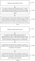
- FIG. 2 is a schematic flowchart of a method for controlling a fresh air device according to a first embodiment of the present application.
- FIG. 3 to FIG. 6 are system schematic diagrams of the fresh air device.
- the fresh air device 100 comprises a casing, a first heat exchange system 3 and a second heat exchange system 4, and the casing is provided with a fresh air channel 1 and an exhaust air channel 2;
- the first heat exchange system 3 is used for exchanging heat between the fresh air channel 1 and the outdoor environment;
- the second heat exchange system 4 is used for exchanging heat between the fresh air channel 1 and the exhaust air channel 2;
- multiple fresh air heat exchangers are provided in the fresh air channel 1; at least one of the multiple fresh air heat exchangers is on the refrigerant flow path of the first heat exchange system 3, and at least one of the multiple fresh air heat exchangers is on the refrigerant flow path of the second heat exchange system 4.
- the fresh air heat exchanger in the first heat exchange system 3 and the fresh air heat exchanger in the second heat exchange system 4 can form two low-pressure ratio refrigerant cycles to achieve high-efficiency operation; at the same time, the heat exchange between the first heat exchange system 3 and the outdoor environment, and the heat exchange between the second heat exchange system 4 and the exhaust air channel 2 are performed, so that both heating and temperature adjustment requirements, and high efficiency and energy saving are achieved.
- the heat exchanger in this embodiment is a device for exchanging heat between refrigerant and air, and the air is cooled and dehumidified or heated and reheated by refrigerants of different temperatures.
- the above-mentioned heat exchanger belongs to the related art, and its specific setting form will not be repeated here.
- the first heat exchange system 3 is a refrigerating cycle system for cooling and reheating the fresh air, absorbing heat through the pre-cooling heat exchanger for cooling, and then reheating the dehumidified air through supercooling.
- the second heat exchange system 4 is used in a refrigeration cycle system for fresh air dehumidification and reheating.
- the dehumidification heat exchanger absorbs heat and dehumidifies, and then reheats the dehumidified air through condensation.
- pre-cooling refers to a process in which the temperature of the refrigerant is lower than that of the air before passing through the heat exchanger, and the air is cooled or dehumidified.
- Dehumidification refers to the process in which the refrigerant is lower than the dew point temperature of the air before passing through the heat exchanger, and the air is cooled and dehumidified.
- Reheating refers to the process in which the temperature of the refrigerant is higher than that of the air before passing through the heat exchanger, and the air is heated and reheated.
- Condensation reheating refers to the process of heating and reheating air with high-temperature gaseous state, or gas-liquid two-phase, or liquid refrigerant.
- the number of fresh air heat exchangers of the first heat exchange system 3 and the second heat exchange system 4 is not limited. In an embodiment, at least two of the fresh air heat exchangers are set on the refrigerant flow path of the first heat exchange system 3; and/or, at least two of the fresh air heat exchangers are set on the refrigerant flow path of the second heat exchanger system 4.
- the relative positions of the fresh air heat exchangers in the first heat exchange system 3 and the second heat exchange system 4 are not limited.
- at least two fresh air heat exchangers provided on the refrigerant flow path of the first heat exchange system 3 are provided alternately with at least two fresh air heat exchangers provided on the refrigerant flow path of the second heat exchange system 4.
- a first refrigerant flow path is formed on the first heat exchange system 3, and the first heat exchange system 3 comprises a first compressor 31, a first four-way valve 32, an outdoor heat exchanger 33, and a first throttling element 34; two fresh air heat exchangers are provided on the first refrigerant flow path, and there is a second throttling element 35 provided between the two fresh air heat exchangers.
- the two fresh air heat exchangers comprise the first fresh air heat exchanger 11 and the second fresh air heat exchanger 12; in the fresh air channel, the first fresh air heat exchanger 11 is on the side of the second fresh air heat exchanger 12 away from the air inlet of the fresh air channel 1; on the first refrigerant flow path, the first throttling element 34, the first fresh air heat exchanger 11, the second throttling element 35, the second fresh air heat exchanger 12 and the first four-way valve 32 are connected in sequence.
- first heat exchange system 3 constitutes a direct expansion air source heat pump system, and the refrigerant directly expands and refrigerates to exchange heat with the air without secondary heat exchange through the refrigerant, thereby improving refrigeration energy efficiency.
- first fresh air heat exchanger 11 and the second fresh air heat exchanger 12 can be provided close to the air inlet of the fresh air channel 1, or can be provided near the air outlet of the fresh air channel 1, which is not limited here.
- the air inlet of the fresh air channel 1 here is the fresh air inlet 1a
- the air outlet of the fresh air channel 1 is the fresh air outlet 1b.
- the heat exchange area of the outdoor heat exchanger 33 is S1
- the heat exchange area of the first fresh air heat exchanger 11 is S2, and S2/S1 ⁇ 0.5.
- the fresh air device 100 further comprises an outdoor fan 331, and the outdoor fan 331 is set corresponding to the outdoor heat exchanger 33.
- the outdoor fan 331 is used to improve the heat dissipation capacity of the outdoor heat exchanger 33.
- a second refrigerant flow path is formed on the second heat exchange system 4, and the second heat exchange system 4 comprises a second compressor 41, a second four-way valve 42, an exhaust air heat exchanger 21, and a third throttling element 43; two fresh air heat exchangers are provided on the second refrigerant flow path, and a fourth throttling element 44 is provided between the two fresh air heat exchangers; and the two fresh air heat exchangers comprise the third fresh air heat exchanger 13 and the fourth fresh air heat exchanger 14; in the fresh air channel, the third fresh air heat exchanger 13 is on the side of the fourth fresh air heat exchanger 14 away from the air inlet of the fresh air channel 1; on the second refrigerant flow path, the third throttling element 43, the third fresh air heat exchanger 13, The fourth throttling element 44, the fourth fresh air heat exchanger 14 and the second four-way valve 42 are connected in sequence.
- the third fresh air heat exchanger 13 and the fourth fresh air heat exchanger 14 can be provided close to the air inlet of the fresh air channel 1, or can be provided near the air outlet of the fresh air channel 1, which is no limited here. It should be noted that the air inlet of the fresh air channel 1 here is the fresh air inlet 1a, and the air outlet of the fresh air channel 1 is the fresh air outlet 1b.
- the heat exchange area of the exhaust air heat exchanger 21 is S4
- the heat exchange area of the third fresh air heat exchanger 13 is S5, and S5/S4 ⁇ 1.5.
- the fresh air device can comprise more or fewer components than shown in the figure, or combine certain components to obtain different component arrangements, for example: setting more heat exchange systems in the fresh air device 100 or adding the number of heat exchangers in the various heat exchange systems.
- the above-mentioned first heat exchange system 3 and the second heat exchange system 4 are provided at the same time, and two sets of direct expansion heat pumps are configured for heat recovery and double reheating and supercooling systems to form two sets of direct heat exchange systems, which enables the fresh air device 100 to have two sets of different condensation temperatures and evaporation temperatures.
- two sets of direct expansion heat pumps are configured for heat recovery and double reheating and supercooling systems to form two sets of direct heat exchange systems, which enables the fresh air device 100 to have two sets of different condensation temperatures and evaporation temperatures.
- the condensation heat recovery and reheat recovery are realized respectively, which improves the system subcooling degree of the first heat exchange system 3 and the second heat exchange system 4, and realize the reheating and subcooling adjustment of multiple working conditions throughout the year by cooperating with throttling components, so that both systems operate at low pressure ratios; in this way, it can improve the operating energy efficiency of the fresh air system throughout the year, and by adjusting the combination of operation modes of the dual systems and controlling the opening of the throttling parts, the temperature requirements of the air outlet in different seasons throughout the year can be achieved, and the comfort of fresh air control can be improved.
- the fresh air temperature is 20°C and the moisture content is 14g/kg; at this time, the user sets reheating and dehumidification, the set temperature is 25°C, and the moisture content is 10g/kg; the second fresh air heat exchanger 12 cools the fresh air to 15°C, and the fourth heat exchanger cools the fresh air to 10°C; and the first fresh air heat exchanger 11 heats the fresh air to 12°C (assuming that the area ratio of the first fresh air heat exchanger 11 with the outdoor heat exchanger 33 is 5%, and the subcooled liquid refrigerant is used for reheating to increase supercooling); and the third fresh air heat exchanger 13 heats the fresh air to 28°C (assuming that the area ratio of the third fresh air heat exchanger 13 with the exhaust air heat exchanger 21 is 100%, the temperature of the outlet air is adjusted by reheating the two-phase refrigerant, and the reheat is increased by decreasing the speed of the exhaust fan 22 or increasing the speed of the first compressor 31), to meet the indoor demand for dehum
- the fresh air temperature is 35°C and the moisture content is 21g/kg
- the user sets reheating and dehumidification at this time, the set temperature is 25°C, and the moisture content is 10g/kg
- the second fresh air heat exchanger 12 cools the fresh air to 20°C
- the fourth fresh air heat exchanger 14 cools the fresh air to 10°C
- the first fresh air heat exchanger 11 heats the fresh air to 15°C (assuming that the area ratio of the first fresh air heat exchanger 11 with the outdoor heat exchanger 33 is 5%, and the subcooled liquid refrigerant is used for reheating to increase supercooling)
- the third fresh air heat exchanger 13 heats the fresh air to 22°C (assuming that the area ratio of the third fresh air heat exchanger 13 with the exhaust air heat exchanger 21 is 100%
- the temperature of the outlet air is adjusted by reheating the two-phase refrigerant, and the reheat is increased by decreasing the speed of the exhaust fan 22 or increasing the speed of the first compressor 31), to meet the indoor demand for
- the fresh air device 100 comprises an integrated compressor 5; and two compression parts are formed in the integrated compressor 5, and each of the compression parts comprises a compression cavity, and an air return port and an exhaust port communicating with the compression cavity. Airflow can be sucked in from the corresponding air return port in the two compression cavities. After compression, it is discharged from the corresponding exhaust port; the two compression parts are respectively located on the refrigerant flow path of the first heat exchange system 3 and the refrigerant flow path of the second heat exchange system 4.
- the fresh air channel 1 is provided with a fresh air inlet 1a and a fresh air outlet 1b; the fresh air device 100 comprises a fresh air fan 15, and the fresh air fan 15 is provided in the fresh air channel 1 and adjacent to the fresh air outlet 1b.
- the fresh air flow to the room is increased by the fresh air fan 15.
- the fresh air inlet 1a is provided with a fresh air filter.
- the purpose of cleaning the air is achieved through the filter, and the quality of the fresh air flowing into the room is improved, so that users can obtain better experience.
- the filter is made of activated carbon.
- the exhaust air channel 2 is provided with an exhaust air inlet 2a and an exhaust air outlet 2b;
- the fresh air device 100 comprises an exhaust fan 22, and the exhaust fan 22 is provided in the exhaust air channel 2 and adjacent to the exhaust air outlet 2b.
- the exhaust fan 22 increases the return air flow rate entering from the exhaust air inlet, thereby improving the exhaust efficiency.
- the working state of each part of the fresh air device 100 is as follows: the fresh air fan extracts fresh air from the outdoor environment, and the fresh air passes through the second fresh air heat exchanger, the fourth fresh air heat exchanger and the first fresh air heat exchanger for four times of heat exchange, and then transports to the indoor environment.
- the exhaust fan extracts exhaust air from the indoor environment, and the exhaust air passes through the exhaust air heat exchanger for a heat exchange and then is transported to the outside.
- the fresh air device may have a cooling mode, a heating mode, and a reheating and dehumidifying mode.
- the first heat exchange system 3 has a high outdoor heat dissipation condensation temperature
- the second heat exchange system 4 has a low exhaust heat dissipation condensation temperature
- the evaporation temperature of the first heat exchange system 3 is increased and the evaporation temperature of the second heat exchange system 4 is decreased to form two low-pressure ratio refrigerant cycles to achieve high-efficiency refrigeration operation.
- the pressure ratio refers to the ratio of the high and low pressures of the (refrigeration) heat pump cycle, which can be obtained through the conversion of the high and low pressure sensors, or the temperature detection of the condenser and the evaporator.
- the refrigerant in the first compressor 31 enters the outdoor heat exchanger 33 through the first four-way valve 32 to condense and dissipate heat, and then after throttling and depressurising through the first throttling element 34, it enters the first fresh air heat exchanger 11 to evaporate and absorb heat, and then enters the second throttling element 35.
- the second throttling element 35 is not throttled, and the refrigerant continues to enter the second fresh air heat exchanger 12 to evaporate and absorb heat, and finally enter the first compressor 31 through the first four-way valve 32 to complete the refrigeration cycle.
- the refrigerant in the second compressor 41 enters the exhaust air heat exchanger 21 through the second four-way valve 42 to condense and dissipate heat and recover the exhaust air heat, and then after throttling and depressurising through the third throttling element 43, it enters the third fresh air heat exchanger 13 to evaporate and absorb heat, and then enters the fourth throttling element 35.
- the fourth throttling element 44 is not throttled, and the refrigerant continues to enter the fourth fresh air heat exchanger 14, and finally enters the second compressor 41 through the second four-way valve 42 to complete the refrigeration cycle.
- the first heat exchange system 3 has a high outdoor heat dissipation condensation temperature
- the second heat exchange system 4 has a low heat dissipation condensation temperature.
- the refrigerant in the first compressor 31 enters the outdoor heat exchanger 33 through the first four-way valve 32 to condense and dissipate heat, and then passes through the first throttling element 34; at this time, the first throttling element 34 does not throttle, the refrigerant continues to enter the first fresh air heat exchanger 11 to condense and dissipate heat, and then pass through the second throttling element 35 for throttling and decreasing pressure, enter the second fresh air heat exchanger 12 to evaporate and absorb heat, and finally enter the first compressor 31 through the first four-way valve 32 to complete the refrigeration cycle.
- the refrigerant in the second compressor 41 enters the exhaust air heat exchanger 21 through the second four-way valve 42 to condense and dissipate heat and recover the exhaust air heat, and then enters the third throttling valve; at this time, the third throttling valve does not throttle, the refrigerant continues to enter the third fresh air heat exchanger 13 to condense and dissipate heat, and then pass through the fourth throttling valve for throttling and decreasing pressure, and then enter the fourth fresh air heat exchanger 14 to evaporate and absorb heat, and finally enter the second compressor 41 through the second four-way valve 42 to complete the refrigeration cycle.
- the outdoor heat absorption evaporation temperature of the first heat exchange system 3 is low, and the exhaust heat absorption evaporation temperature of the second heat exchange system 4 is high.
- the condensation temperature of the first heat exchange system 3 is decreased, and increasing the condensing temperature of the second heat exchange system 4, two low-pressure ratio refrigerant cycles are formed to realize high-efficiency heating operation.
- the refrigerant in the first compressor 31 enters the second fresh air heat exchanger 12 through the first four-way valve 32 to condense and dissipate heat, and then passes through the second throttling element 35; at this time, the second throttling element 35 is not throttling, the refrigerant continues to enter the first fresh air heat exchanger 11 to condense and dissipate heat, and then pass through the first throttling element 34 for throttling and decreasing pressure, then enter the outdoor heat exchanger 33 to evaporate and absorb heat, and finally enter the first compressor 31 through the first four-way valve 32 to complete the refrigeration cycle.
- the refrigerant in the second compressor 41 enters the fourth fresh air heat exchanger 14 through the second four-way valve 42 to condense and dissipate heat, and then enters the fourth throttling element 44; at this time, the fourth throttling element 44 does not throttle, and the refrigerant continues to enter the third fresh air heat exchanger 13 to condense and dissipate heat, and then pass through the third throttling element 43 for throttling and decreasing pressure, then enters the exhaust air heat exchanger 21 to evaporate and absorb heat and recover the exhaust air heat, and finally enters the second compressor 41 through the second four-way valve 42 to complete the refrigeration cycle.
- the first throttling element 34 of the first heat exchange system 3 can be controlled to work for throttling and decreasing pressure; and the second throttling element 35 can be controlled to stop working or open a bypass, so that the first fresh air heat exchanger 11 and the second fresh air heat exchanger 12 operate as an evaporator to cool the fresh air, increase the area of the evaporator of the first heat exchange system 3, and increase the evaporation temperature of the first heat exchange system 3, thereby increasing the energy efficiency of the first heat exchange system 3.
- the third throttling element 43 in the second heat exchange system 4 can be controlled to work for throttling and decreasing pressure; and the fourth throttling element 44 can be controlled to stop working or open a bypass, so that the third fresh air heat exchanger 13 and the fourth fresh air exchanger 14 all operate as evaporators to cool the fresh air, increase the area of the evaporator of the second heat exchange system 4, increase the evaporation temperature of the second heat exchange system 4, and thereby improving the energy efficiency of the second heat exchange system 4.
- the area of the heat exchanger needs to be limited; the area of the first fresh air heat exchanger 11 should be less than or equal to 50% of the area of the outdoor heat exchanger 33, and the area of the third fresh air heat exchanger 13 should be less than or equal to 150% of the area of the exhaust air heat exchanger 21.
- the fresh air device can comprise more or fewer components than shown in the figure, or combine certain components to obtain different component arrangements, for example: setting more heat exchange systems in the fresh air device or increasing the heat exchange in each heat exchange system number of devices.
- the method for controlling the fresh air device comprises the following steps: Step S10: obtaining the target operation mode.
- the execution subject of this embodiment is the fresh air device mentioned above, and the fresh air device may comprise a fresh air fan and an air conditioner with a fresh air function.
- the operation of each component in the fresh air device can be driven by a core controller, so the execution subject of this embodiment can also be the core controller in the above-mentioned fresh air device, and the core controller can be the above-mentioned processor.
- the embodiment describes the core controller as the execution subject.
- the mode setting instruction can be an instruction sent to the core controller of the fresh air device when the user controls the fresh air device to change the operation mode through a remote control or other means, or it can be an instruction that is automatically generated and sent to the core controller when the fresh air device determines that the mode needs to be changed according to the surrounding environment information.
- the mode setting instruction may have a mode identification parameter, and the mode setting instruction may be analyzed to obtain the mode identification parameter in the mode setting instruction, and the target operation mode may be determined according to the mode identification parameter.
- Step S20 adjusting the operation states of the first heat exchange system and the second heat exchange system according to the target operation mode, so that the fresh air device is in a state of high energy efficiency.
- the fresh air device involved in this embodiment has a first heat exchange system and a second heat exchange system.
- the target operation mode it is necessary to select different control methods according to the target operation mode to adjust the operation parameters of the first heat exchange system and the second heat exchange system, and adjust the operation state of each component in the first heat exchange system and the second heat exchange system, so as to improve the energy efficiency state and make the fresh air equipment operate in a high energy efficiency state.
- the fresh air device in this embodiment comprises a first heat exchange system and a second heat exchange system.
- the target operation mode is determined according to the mode setting instruction, and the operation parameters of the first heat exchange system and the second heat exchange system in the fresh air device are adjusted according to the target operation mode to improve the energy efficiency state of the fresh air device. Since multiple heat exchange systems are provided in the fresh air device, the operation mode combination of the first heat exchange system and the second heat exchange system can be adjusted according to the target operation mode to meet the requirements of the outlet air temperature in different seasons throughout the year, and it can also be adjusted according to the target operation mode.
- the target operation mode adjusts the operation state of the first heat exchange system and the second heat exchange system, so that the fresh air device is in a state of high energy efficiency, so that the fresh air device can meet the heating and temperature adjustment requirements while ensuring efficiency.
- FIG. 7 is a schematic flowchart of a method for controlling a fresh air device according to a second embodiment of the present application.
- the step S20 of the method for controlling the fresh air device in this embodiment may comprise: Step S201: When the target operation mode is the cooling mode, adjusting the operation modes of the first heat exchange system and the second heat exchange system to the cooling mode.
- the target operation mode is the cooling mode
- the first heat exchange system and the second heat exchange system can be adjusted to operate in the cooling mode.
- the operation mode of the first heat exchange system can be changed to cooling mode by adjusting the first four-way valve in the first heat exchange system, for example: taking FIG. 3 as an example, by adjusting the state of the first four-way valve 32, the refrigerant circulation flow direction in the first heat exchange system is changed, so that the refrigerant circulation flow direction in the first heat exchange system becomes: first compressor 31-first four-way valve 32-outdoor heat exchanger 33-the first throttling element 34-the first fresh air heat exchanger 11-the second throttling element 35-the second fresh air heat exchanger 12-the first four-way valve 32-the first compressor 31, so that the first heat exchange system operates in cooling mode.
- the second four-way valve in the second heat exchange system can be adjusted to change the operation mode of the second heat exchange system to cooling mode, for example: taking FIG. 3 as an example, by adjusting the state of the second four-way valve 42, the circulation flow direction of the refrigerant in the second heat exchange system is changed, so that the circulation flow direction of the refrigerant in the second heat exchange system becomes: second compressor 41-second four-way valve 42-exhaust air heat exchanger 21-third throttling element 43-third fresh air heat exchanger 13-fourth throttling element 44-fourth fresh air heat exchanger 14-second four-way valve 42-second compressor 41, so that the second heat exchange system operates in cooling mode.
- Step S202 controlling the first fresh air heat exchanger, the second fresh air heat exchanger, the third fresh air heat exchanger, and the fourth fresh air heat exchanger to operate as evaporators, so that the fresh air device is in a state of high energy efficiency.
- first fresh air heat exchanger and the second fresh air heat exchanger in the first heat exchange system and the third fresh air heat exchanger and the fourth heat exchanger in the second heat exchange system are controlled to operate as evaporators, absorb the heat in the fresh air, thereby cooling the fresh air, which can greatly increase the area of the evaporator that the fresh air contacts, and improve the energy efficiency when cooling the fresh air, thereby improving the energy efficiency of the fresh air device.
- the first throttling element of the first heat exchange system can be controlled to work to throttle and decrease pressure
- the second throttling component can be controlled to stop working or open the bypass, so that the first fresh air heat exchanger and the second fresh air heat exchanger operate as an evaporator to cool the fresh air, increase the area of the evaporator of the first heat exchange system, increase the evaporation temperature of the first heat exchange system, and thereby improving the energy efficiency of the first heat exchange system.
- the third throttling element in the second heat exchange system can be controlled to work for throttling and decreasing pressure
- the fourth throttling element can be controlled to stop working or open the bypass, so that the third fresh air heat exchanger and the fourth fresh air heat exchanger all operate as evaporators to cool the fresh air, increase the area of the evaporator of the second heat exchange system, and increase the evaporation temperature of the second heat exchange system, thereby improving the energy efficiency of the second heat exchange system.
- the first operation temperature parameter and the first target temperature parameter can also be obtained; according to the first operation temperature parameter and the first target temperature parameter, determining whether the cooling capacity is too high, and adjusting the operation parameters of the fresh air device according to the judgment result.
- the first operation temperature parameter may be any one or more of indoor temperature, outlet air temperature, or fresh air temperature; the indoor temperature may be the temperature in the room served by the fresh air device, and the outlet air temperature may be the temperature of the air supplied by the fresh air device when the fresh air device is supplying air to the room, and the fresh air temperature may be the temperature of the fresh air inhaled by the fresh air device.
- the judgment result is that the cooling capacity is too low; if the first operation temperature parameter is smaller than the first target temperature parameter, the judgment result is that the cooling capacity is too high.
- the first target temperature parameter may be set by a user, or may be preset by a manager of the fresh air device, and the first target temperature parameter corresponds to a cooling mode, which is not limited in this embodiment.
- the operation parameters of the fresh air device need to be adjusted to decrease the cooling capacity of the fresh air device; if the cooling capacity is too low, the operation parameters of the fresh air device need to be adjusted to increase the cooling capacity of the fresh air device, thereby ensuring that the indoor temperature meets the actual needs of users and improving user's comfort.
- the rotation speed of the compressor in the first heat exchange system or the second heat exchange system can be decreased; the opening degree of the first throttling component in the first heat exchange system can be increased; the opening degree of the second throttling component in the second heat exchange system can be increased, or the rotation speed of the second fan in the fresh air device can be decreased; at least one of them can be performed, so as to decrease the cooling capacity of the fresh air device; the priority of adjusting the first heat exchange system is higher than that of the second heat exchange system.
- the cooling capacity is too low, that is, the first operation temperature parameter is greater than or equal to the first target temperature parameter, it is necessary to increase the cooling capacity of the fresh air device. Therefore, at least one of increasing the rotation speed of the compressor in the first heat exchange system or the second heat exchange system, decreasing the opening degree of the first throttling component in the first heat exchange system, decreasing the opening degree of the third throttling component in the second heat exchange system, increasing the rotation speed of the third fan in the second heat exchange system or increasing the rotation speed of the first fan in the first heat exchange system can be performed to increase the cooling capacity of the fresh air device; the priority of adjusting the second heat exchange system is higher than that of the first heat exchange system.
- the value range of the first target temperature parameter can be determined according to the first operation temperature parameter, for example: if the first operation temperature parameter is indoor temperature, the value range of the first target temperature parameter can be 15-32°C; if the first operation temperature parameter is the fresh air temperature, the value range of the first target temperature parameter can be 10-50°C; if the first operation temperature parameter is the outlet air temperature, the value range of the first target temperature parameter can be 5-32°C.
- the operation parameters of the components in the first heat exchange system and the second heat exchange system are adjusted, so that the fresh air heat exchangers in the first heat exchange system and the second heat exchange system all operate as evaporators to cool down the fresh air, thereby increasing the area of the evaporator in the fresh air device, improving the energy efficiency of the fresh air device in cooling mode, and improving the energy efficiency of fresh air device in cooling mode state.
- FIG. 8 is a schematic flowchart of the method for controlling the fresh air device according to a third embodiment of the present application.
- the step S20 of the method for controlling the fresh air device in this embodiment may comprise: Step S201': when the target operation mode is a dehumidification mode or a reheat dehumidification mode, adjusting the operation modes of the first heat exchange system and the second heat exchange system to a cooling mode.
- the target operation mode is dehumidification mode or reheating dehumidification mode
- the fresh air taken in by the fresh air device needs to be cooled and dehumidified first, and then heated.
- the first heat exchange system and the second heat exchange system are adjusted to operate in cooling mode.
- the operation mode of the first heat exchange system can be changed to cooling mode by adjusting the first four-way valve in the first heat exchange system, for example: taking FIG. 3 as an example, by adjusting the state of the first four-way valve 32, the refrigerant circulation flow direction in the first heat exchange system is changed, so that the refrigerant circulation flow direction in the first heat exchange system becomes: first compressor 31-first four-way valve 32-outdoor heat exchanger 33-the first throttling element 34-the first fresh air heat exchanger 11-the second throttling element 35-the second fresh air heat exchanger 12-the first four-way valve 32-the first compressor 31, so that the first heat exchange system operates in cooling mode.
- the operation mode of the second heat exchange system can be changed to cooling mode by adjusting the second four-way valve in the second heat exchange system, for example: taking FIG. 3 as an example, by adjusting the state of the second four-way valve 42, the circulation flow direction of the refrigerant in the second heat exchange system is changed, so that the circulation flow direction of the refrigerant in the second heat exchange system becomes: second compressor 41-second four-way valve 42-exhaust air heat exchanger 21-third throttling element 43-third fresh air heat exchanger 13-fourth throttling element 44-fourth fresh air heat exchanger 14-second four-way valve 42-second compressor 41, so that the second heat exchange system operates in cooling mode.
- Step S202' controlling the first fresh air heat exchanger to operate as a condenser, and the second fresh air heat exchanger to operate as an evaporator.
- the first throttling element in the first heat exchange system can be controlled to stop working or open the bypass, and the second throttling element can be controlled to work for throttling and decreasing pressure, so that the first fresh air heat exchanger operates as a condenser to preheat the fresh air, and the second fresh air heat exchanger operates as an evaporator to cool and dehumidify the fresh air, thereby decreasing the condensation temperature and increasing the subcooling degree, thereby improving the energy efficiency of the first heat exchange system.
- Step S203' controlling the third fresh air heat exchanger to operate as a condenser, and the fourth fresh air heat exchanger to operate as an evaporator, so that the fresh air device is in a state of high energy efficiency.
- the third throttling element in the second heat exchange system can be controlled to stop working or open the bypass, and the fourth throttling element can be controlled to work for throttling and decreasing pressure, so that the third fresh air heat exchanger can be used as a condenser to reheat the fresh air; and the fourth fresh air heat exchanger operates as an evaporator to cool and dehumidify the fresh air, thereby reducing the condensation temperature, and increasing the degree of supercooling, thereby improving the energy efficiency of the second heat exchange system and making the fresh air device in a state of high energy efficiency.
- the operation humidity parameter, target humidity parameter, second operation temperature parameter and second target temperature parameter can be obtained; the operation state of the fresh air device can be adjusted according to the operation humidity parameter, the target humidity parameter, the second operation temperature parameter and the second target temperature parameter.
- the second operation temperature parameter may be any one or more of indoor temperature, outlet air temperature, or fresh air temperature.
- the operation humidity parameter can be the indoor humidity, the humidity of the outlet air or the humidity of the fresh air.
- the indoor humidity can be the humidity of the room served by the fresh air device, and the humidity of the outlet air can be the air sent to the room by the fresh air device.
- the moisture content of the fresh air may be the moisture content of the fresh air inhaled by the fresh air device.
- the second target temperature parameter and the target humidity parameter correspond to the reheating and dehumidification mode, which can be set by the user, or can be set in advance by the management personnel of the fresh air device.
- the operation humidity parameter is compared with the target humidity parameter; and when the operation humidity parameter is greater than the target humidity parameter, at least one of the following is performed: increasing the rotation speed of the compressor in the first heat exchange system or the second heat exchange system, decreasing the opening degree of the second throttling element in the first heat exchange system or the opening degree of the fourth throttling element in the second heat exchange system; and at this time, it is not necessary to compare the second temperature operation parameter with the second target temperature parameter;
- the operation humidity parameter is less than the target humidity parameter, at least one of the following is performed: decreasing the rotation speed of the compressor in the first heat exchange system or the second heat exchange system, increasing the opening degree of the second throttling element in the first heat exchange system, or increasing the opening degrees of the fourth throttling element in the second heat exchange system; and at this time, the second temperature operation parameter can be compared with the second target temperature parameter, and when the second temperature operation parameter is greater than the second target temperature parameter, at least one of the following is performed: increasing the rotation speed of the third fan in
- the value range of the second target temperature parameter can be determined according to the second operation temperature parameter, for example: if the second operation temperature parameter is indoor temperature, the value range of the second target temperature parameter can be 15-32°C; if the second operation temperature parameter is the fresh air temperature, the value range of the second target temperature parameter can be 10-50°C; if the second operation temperature parameter is the outlet air temperature, the value range of the second target temperature parameter can be 5-32°C.
- the value range of the target humidity parameter can be determined according to the operation humidity parameter, for example: if the operation humidity parameter is indoor humidity, the value range of the target humidity parameter can be 5-14g/kg; if the operation humidity parameter is the moisture content of the air outlet, the value range of the target humidity parameter can be 5-16g/kg; if the operation humidity parameter is the moisture content of the fresh air, the value range of the target humidity parameter can be 5-18g/kg.
- the operation parameters of the components in the first heat exchange system and the second heat exchange system are adjusted so that the first fresh air heat exchanger in the first heat exchange system operates as a condenser to preheat the fresh air, and the second fresh air heat exchanger operates as an evaporator to cool and dehumidify the fresh air; and the third fresh air heat exchanger in the second heat exchange system operates as a condenser to reheat the fresh air, and the fourth fresh air heat exchanger operates as an evaporator to cool and dehumidify the fresh air, thereby realizing the dehumidification and reheating of the fresh air and meeting the indoor demand for dehumidification and reheating.
- FIG. 9 is a schematic flowchart of the method for controlling the fresh air device according to a fourth embodiment of the present application.
- the step S20 of the method for controlling the fresh air device in this embodiment may comprise: Step S201": when the target operation mode is the heating mode, adjusting the operation modes of the first heat exchange system and the second heat exchange system to the heating mode.
- the target operation mode is the heating mode, it means that the fresh air taken in by the fresh air device needs to be heated. At this time, the first heat exchange system and the second heat exchange system can be adjusted to operate in the heating mode .
- the operation mode of the first heat exchange system can be changed to the heating mode by adjusting the first four-way valve in the first heat exchange system, for example: taking FIG. 3 as an example, by adjusting the state of the first four-way valve 32, the refrigerant circulation flow direction in the first heat exchange system is changed, so that the refrigerant circulation flow direction in the first heat exchange system becomes: first compressor 31-first four-way valve 32-second fresh air heat exchanger 12-second throttling element 35-first fresh air heat exchanger 11-first throttling element 34-outdoor heat exchanger 33-first four-way valve 32-first compressor 31, so that the first heat exchange system operates in heating mode.
- the operation mode of the second heat exchange system can be changed to the heating mode by adjusting the second four-way valve in the second heat exchange system, for example: taking FIG. 3 as an example, by adjusting the state of the second four-way valve 42, the refrigerant circulation flow direction in the second heat exchange system is changed, so that the refrigerant circulation flow direction in the second heat exchange system becomes: second compressor 41-second four-way valve 42-fourth fresh air heat exchanger 14-fourth throttling element 44-third fresh air heat exchanger 13-third throttling element 43-exhaust air heat exchanger 21-second four-way valve 42-second compressor 41, so that the second heat exchange system operates in heating mode.
- Step S202" controlling the first fresh air heat exchanger, the second fresh air heat exchanger, the third fresh air heat exchanger, and the fourth fresh air heat exchanger to operate as condensers, so that the fresh air device is in a state of high energy efficiency.
- first fresh air heat exchanger and the second fresh air heat exchanger in the first heat exchange system and the third fresh air heat exchanger and the fourth heat exchanger in the second heat exchange system are both controlled to operate as condensers to heat the fresh air, which can greatly increase the area of the condenser that the fresh air contacts, and improve the energy efficiency when heating the fresh air, thereby improving the energy efficiency of the fresh air device.
- the first throttling element in the first heat exchange system can be controlled to work for throttling and decreasing pressure
- the second throttling element can be controlled to stop working or open the bypass, so that the first fresh air heat exchanger and the second fresh air heat exchanger both operate as condensers to heat the fresh air, which can increase the condenser area of the second heat exchange system, decrease the condensation temperature, and increase the degree of subcooling, thereby improving the energy efficiency of the first heat exchange system.
- the third throttling component in the second heat exchange system can be controlled to work for throttling and decreasing pressure, and the second throttling element is controlled to stop working or open the bypass, so that the third fresh air heat exchanger and the fourth fresh air heat exchanger all operate as condensers to heat the fresh air, which can increase the condenser area of the second heat exchange system, decrease the condensation temperature, and increase the subcooling temperature, thereby improving the energy efficiency of the second heat exchange system.
- step S202" described in this embodiment the third operation temperature parameter and the third target temperature parameter can also be obtained; it is determined whether the heating capacity is too high according to the third operation temperature parameter and the third target temperature parameter, and the operation state of the fresh air device is adjusted according to the judgment result.
- the third operation temperature parameter may be any one or more of indoor temperature, outlet air temperature, or fresh air temperature.
- the indoor temperature may be the temperature in the room served by the fresh air device
- the outlet air temperature may be the temperature of the air supplied by the fresh air device when it supplies air to the room
- the fresh air temperature may be the temperature of the fresh air inhaled by the fresh air device.
- the third operation temperature parameter it is possible to compare the third operation temperature parameter with the third target temperature parameter, and it is determined whether the heating capacity is too high according to the comparison result, for example: if the third operation temperature parameter is lower than the target temperature parameter, the judgment result is that the heating capacity is too low; if the third operation temperature parameter is greater than the target temperature parameter, the judgment result is that the heating capacity is too high.
- the target temperature parameter may be set by the user, or may be preset by the manager of the fresh air device, and the target temperature parameter corresponds to the cooling mode, which is not limited in this embodiment.
- the heating capacity is too high, it is necessary to adjust the operation parameters of the fresh air device to decrease the heating capacity of the fresh air device; if the heating capacity is too low, it is necessary to adjust the operation parameters of the fresh air device to increase the heating capacity of the fresh air device, thereby ensuring that the indoor temperature meets the actual needs of users and improving user comfort.
- the heating capacity is too high, that is, the third operation temperature parameter is greater than the third target temperature parameter, it is necessary to decrease the heating capacity of the fresh air device. Therefore, at least one of the following is performed: decreasing the rotation speed of the compressor in the first heat exchange system or the second heat exchange system, increasing the opening degree of the first throttling element in the first heat exchange system, increasing the opening degree of the second throttling element in the second heat exchange system, decreasing the rotation speed of the third fan in the fresh air device, or decreasing the rotation speed of the first fan in the first heat exchange system; the adjustment priority of the first heat exchange system is higher than that of the second heat exchange system.
- the heating capacity is too low, that is, the third operation temperature parameter is less than or equal to the third target temperature parameter, it is necessary to increase the heating capacity of the fresh air device. Therefore, at least one of the following is performed: increasing the rotation speed of the compressor in the first heat exchange system or the second heat exchange system, decreasing the opening degree of the first throttling element in the first heat exchange system, decreasing the opening degree of the second throttling element in the second heat exchange system, increasing the rotation speed of the third fan in the fresh air device or increasing the rotation speed of the first fan in the first heat exchange system; the adjustment priority of the second heat exchange system is higher than that of the first heat exchange system.
- the value range of the third target temperature parameter can be determined according to the third operation temperature parameter, for example: if the third temperature parameter is indoor temperature, the value range of the third target temperature parameter can be 12-32°C; if the third operation temperature parameter is the fresh air temperature, the value range of the third target temperature parameter can be -30-25°C; if the third operation temperature parameter is the outlet air temperature, the value range of the third target temperature parameter can be 15- 60°C.
- the operation parameters of the components in the first heat exchange system and the second heat exchange system are adjusted, so that all the fresh air heat exchangers in the first heat exchange system and the second heat exchange system operate as condensers to heat the fresh air, thereby increasing the area of the condenser in the fresh air device, improving the operating energy efficiency of the fresh air device in the heating mode, and improving the operating energy efficiency state of the fresh air device in the heating mode.
- the embodiment of the present application also provides a storage medium, on which a control program for a fresh air device is stored, and when the control program for the fresh air device is executed by a processor, the steps of the method for controlling the fresh air device as described above are realized.
- FIG. 10 is a structural block diagram of an apparatus for controlling a fresh air device according to a first embodiment of the present application.
- the instruction receiving module 100 configured to obtain a target operation mode.
- the mode setting instruction can be an instruction sent to the core controller of the fresh air device when the user controls the fresh air device to change the operation mode through a remote control or other means, or it can be an instruction automatically generated and sent to the core controller when the fresh air device determines that the mode needs to be changed according to the surrounding environment information.
- the mode setting instruction may have a mode identification parameter, and the mode setting instruction may be analyzed to obtain the mode identification parameter in the mode setting instruction, and the target operation mode may be determined according to the mode identification parameter.
- the parameter adjustment module 200 configured to adjust the operation states of the first heat exchange system and the second heat exchange system according to the target operation mode, so that the fresh air device is in a state of high energy efficiency.
- the fresh air device involved in this embodiment has a first heat exchange system and a second heat exchange system.
- different control methods are selected according to the target operation mode to adjust the operation parameters of the first heat exchange system and the second heat exchange system, the operation state of each component in the first heat exchange system and the second heat exchange system is modified, thereby improving the energy efficiency state, making fresh air device operate in a state of high energy efficiency.
- the fresh air device in this embodiment comprises a first heat exchange system and a second heat exchange system.
- the target operation mode is determined according to the mode setting instruction, and the operation parameters of the first heat exchange system and the second heat exchange system in the fresh air device are adjusted according to the target operation mode, thereby improving the energy efficiency state of the fresh air device. Since multiple heat exchange systems are provided in the fresh air device, the operation mode combination of the first heat exchange system and the second heat exchange system can be adjusted according to the target operation mode to meet the requirements of the outlet air temperature in different seasons throughout the year.
- the operation state of the first heat exchange system and the second heat exchange system is adjusted according to the target operation mode, so that the fresh air device is in a state of high energy efficiency, and the fresh air device can meet the heating and temperature adjustment requirements while ensuring efficiency.
- the methods of the above embodiments can be implemented by means of software plus a necessary general-purpose hardware platform, and of course also by hardware, but in many cases the former is better implementation.
- the technical solution of the present application can be embodied in the form of a software product in essence or the part that contributes to the related art, and the computer software product is stored in a storage medium (such as a read only memory (ROM)/ random access memory (RAM), magnetic disk, optical disk), comprising several instructions to make a terminal device (which can be a mobile phone, computer, server, or network device, etc.) execute the methods described in various embodiments of the present application.
- ROM read only memory
- RAM random access memory
- a terminal device which can be a mobile phone, computer, server, or network device, etc.
Landscapes
- Engineering & Computer Science (AREA)
- Mechanical Engineering (AREA)
- General Engineering & Computer Science (AREA)
- Chemical & Material Sciences (AREA)
- Combustion & Propulsion (AREA)
- Physics & Mathematics (AREA)
- Thermal Sciences (AREA)
- Signal Processing (AREA)
- Fuzzy Systems (AREA)
- Mathematical Physics (AREA)
- Fluid Mechanics (AREA)
- Air Conditioning Control Device (AREA)
Abstract
Description
- The present application claims priority to
Chinese Patent Application Nos. 202111417547.8 202122922745.1, both filed on November 24, 2021 - The present application relates to the technical field of fresh air device, in particular to a method for controlling a fresh air device, an apparatus, a storage medium and a fresh air device.
- Nowadays, with the improvement of the quality of life, the requirements for the indoor thermal environment are no longer just hot and cold, but also rise to the demand for health, which puts forward higher requirements for freshness and cleanliness. As an effective and important solution, fresh air is increasingly applied.
- Due to the limitations of price, installation and size of air conditioners in the traditional room, the fresh air is only filtered and sent directly into the room, and the air conditioner bears the load. On the other hand, with the development of building energy conservation, the airtightness is getting better and better, and ultra-low energy consumption buildings are increasing day by day. Fresh air fans, as the key indoor environmental treatment device, not only clean the fresh air, but also need to deal with the temperature and humidity of the fresh air. No matter what kind of fresh air device it is, the heat and humidity treatment of fresh air is added on the basis of the original indoor heat and humidity environment treatment, which brings about an increase in energy consumption. Therefore, some fresh air energy-saving solutions have appeared in the development stage of fresh air fans. The existing mature product solutions are mainly full heat exchange recovery, or heat pump reheat recovery, or dual cold source pre-cooling and dehumidification separation.
- However, the full heat exchange recovery can achieve heat and moisture recovery, but there are difficult problems in processing, large size, large wind resistance, easy to be dirty and blocked, easy to freeze in winter, high energy consumption of fans, high cost, and efficiency limited by indoor and outdoor temperature differences. Heat pump reheat recovery can improve heat pump efficiency, but it is only efficient in cooling and dehumidification, and most of them are only one-level reheat recovery. The fresh air temperature adjustment capacity is limited, and dehumidification and energy saving cannot be considered at the same time. The dual cold source pre-cooling and dehumidification separation can improve the energy waste of refrigeration and dehumidification, but the fresh air temperature adjustment capacity is limited, and the water cooling technical solution itself has heat loss from secondary heat exchange, and there is a waste of cooling heat, which only improves the processing efficiency of fresh air. However, the energy consumption is transferred to the refrigeration unit.
- None of the above technical solutions can take into account the needs of heating and temperature adjustment well. In winter, electric auxiliary heating is used to heat up, or some are used in conjunction with full heat exchange. However, the problem of freezing of the full heat exchanger at low temperatures and high humidity still needs to be solved, so the efficiency in winter is very low.
- The above content is only used to assist in understanding the technical solution of the present application, and does not mean that the above content is admitted as related art.
- The main purpose of the present application is to provide a method for controlling a fresh air device, an apparatus, a storage medium and a fresh air device, aiming to solve the technical problem that the existing fresh air device cannot meet the heating and temperature adjustment requirements well and has low efficiency.
- To achieve the above purpose, the present application provides a method for controlling a fresh air device, applied to a fresh air device; the fresh air device comprises a first heat exchange system configured for exchanging heat between a fresh air channel and an outdoor environment, and a second heat exchange system configured for exchanging heat between the fresh air channel and an exhaust air channel;
- characterized in that the method comprises:
- obtaining a target operation mode; and
- adjusting operation states of the first heat exchange system and the second heat exchange system according to the target operation mode, so that the fresh air device is in a state of high energy efficiency.
- In an embodiment, the first heat exchange system comprises a first fresh air heat exchanger and a second fresh air heat exchanger provided in the fresh air channel, and the second heat exchange system comprises a third fresh air heat exchanger and a fourth fresh air heat exchanger provided in the fresh air channel;
- the adjusting the operation states of the first heat exchange system and the second heat exchange system according to the target operation mode, so that the fresh air device is in the state of high energy efficiency comprises:
- in response to that the target operation mode is a cooling mode, adjusting operation modes of the first heat exchange system and the second heat exchange system to the cooling mode; and
- controlling the first fresh air heat exchanger, the second fresh air heat exchanger, the third fresh air heat exchanger, and the fourth fresh air heat exchanger to operate as evaporators, so that the fresh air device is in the state of high energy efficiency.
- In an embodiment, the fresh air device further comprises an outdoor heat exchanger provided in the outdoor environment, a second fan provided in the fresh air channel, and a third fan provided in the exhaust air channel; the first heat exchange system comprises a first compressor, a first four-way valve, a first throttling element, a second throttling element and an outdoor heat exchanger; the first compressor, the first four-way valve, the outdoor heat exchanger, the first throttling element, the first fresh air heat exchanger, the second throttling element, and the second fresh air heat exchanger are sequentially connected in series; the second heat exchange system comprises a second compressor, a second four-way valve, a third throttling element, a fourth throttling element, and an exhaust air heat exchanger; the second compressor, the second four-way valve, the exhaust air heat exchanger, the third throttling element, the third fresh air heat exchanger, the fourth throttling element, and the fourth fresh air heat exchanger are sequentially connected in series;
- after the controlling the first fresh air heat exchanger, the second fresh air heat exchanger, the third fresh air heat exchanger, and the fourth fresh air heat exchanger to operate as the evaporators, so that the fresh air device is in the state of high energy efficiency, the method further comprises:
- obtaining a first operation temperature parameter and a first target temperature parameter;
- in response to that the first operation temperature parameter is lower than the first target temperature parameter, performing at least one of decreasing a rotation speed of the first compressor, increasing an opening degree of the first throttling element, decreasing a rotation speed of the second fan, decreasing a rotation speed of the second compressor and increasing an opening degree of the third throttling element; and
- in response to that the first operation temperature parameter is greater than the first target temperature parameter, performing at least one of increasing the rotation speed of the first compressor, decreasing the opening degree of the first throttling element, increasing the rotation speed of the first fan, increasing the rotation speed of the third fan, increasing the rotation speed of the second compressor, and decreasing the opening degree of the third throttling element.
- In an embodiment, the first heat exchange system comprises a first fresh air heat exchanger and a second fresh air heat exchanger provided in the fresh air channel, and the second heat exchange system comprises a third fresh air heat exchanger and a fourth fresh air heat exchanger provided in the fresh air channel;
- the adjusting the operation states of the first heat exchange system and the second heat exchange system according to the target operation mode, so that the fresh air device is in the state of high energy efficiency comprises:
- in response to that the target operation mode is a dehumidification mode or a reheat dehumidification mode, adjusting operation modes of the first heat exchange system and the second heat exchange system to a cooling mode;
- controlling the first fresh air heat exchanger to operate as a condenser, and controlling the second fresh air heat exchanger to operate as an evaporator; and
- controlling the third fresh air heat exchanger to operate as a condenser, and controlling the fourth fresh air heat exchanger to operate as an evaporator, so that the fresh air device is in a state of high energy efficiency.
- In an embodiment, the fresh air device further comprises an outdoor heat exchanger provided in the outdoor environment, a second fan provided in the fresh air channel, and a third fan provided in the exhaust air channel; the first heat exchange system comprises a first compressor, a first four-way valve, a first throttling element, a second throttling element and an outdoor heat exchanger; the first compressor, the first four-way valve, the outdoor heat exchanger, the first throttling element, the first fresh air heat exchanger, the second throttling element, and the second fresh air heat exchanger are sequentially connected in series; the second heat exchange system comprises a second compressor, a second four-way valve, a third throttling element, a fourth throttling element, and an exhaust air heat exchanger; the second compressor, the second four-way valve, the exhaust air heat exchanger, the third throttling element, the third fresh air heat exchanger, the fourth throttling element, and the fourth fresh air heat exchanger are sequentially connected in series;
- after the controlling the third fresh air heat exchanger to operate as the condenser, and controlling the fourth fresh air heat exchanger to operate as the evaporator, so that the fresh air device is in the state of high energy efficiency, the method further comprises:
- obtaining an operation humidity parameter and a target humidity parameter;
- in response to that the operation humidity parameter is less than the target humidity parameter, performing at least one of decreasing a rotation speed of the first compressor, increasing an opening degree of the second throttling element, decreasing a rotation speed of the second compressor, and increasing an opening degree of the fourth throttle element; and
- in response to that the operation humidity parameter is greater than the target humidity parameter, performing at least one of increasing the rotation speed of the first compressor, decreasing the opening degree of the second throttling element, increasing the rotation speed of the second compressor, and decreasing the opening degree of the fourth throttle element.
- In an embodiment, after the in response to that the operation humidity parameter is less than the target humidity parameter, performing at least one of decreasing the rotation speed of the first compressor, increasing the opening degree of the second throttling element, decreasing the rotation speed of the second compressor, and increasing the opening degree of the fourth throttle element, the method further comprises:
- obtaining a second operation temperature parameter and a second target temperature parameter;
- in response to that the second operation temperature parameter is lower than the second target temperature parameter, performing at least one of decreasing the rotation speed of the third fan, increasing the rotation speed of the second compressor, and decreasing the opening degree of the fourth throttling element; and
- in response to that the second operation temperature parameter is greater than the second target temperature parameter, performing at least one of increasing the rotation speed of the third fan, decreasing the rotation speed of the second compressor, and increasing the opening degree of the fourth throttling element.
- In an embodiment, the first heat exchange system comprises a first fresh air heat exchanger and a second fresh air heat exchanger provided in the fresh air channel, and the second heat exchange system comprises a third fresh air heat exchanger and a fourth fresh air heat exchanger provided in the fresh air channel;
- the adjusting the operation states of the first heat exchange system and the second heat exchange system according to the target operation mode, so that the fresh air device is in the state of high energy efficiency comprises:
- in response to that the target operation mode is a heating mode, adjusting operation modes of the first heat exchange system and the second heat exchange system to the heating mode; and
- controlling the first fresh air heat exchanger, the second fresh air heat exchanger, the third fresh air heat exchanger, and the fourth fresh air heat exchanger to operate as condensers, so that the fresh air device is in the state of high energy efficiency.
- In an embodiment, the fresh air device further comprises an outdoor heat exchanger provided in the outdoor environment, a second fan provided in the fresh air channel, and a third fan provided in the exhaust air channel; the first heat exchange system comprises a first compressor, a first four-way valve, a first throttling element, a second throttling element and an outdoor heat exchanger; the first compressor, the first four-way valve, the outdoor heat exchanger, the first throttling element, the first fresh air heat exchanger, the second throttling element, and the second fresh air heat exchanger are sequentially connected in series; the second heat exchange system comprises a second compressor, a second four-way valve, a third throttling element, a fourth throttling element, and an exhaust air heat exchanger; the second compressor, the second four-way valve, the exhaust air heat exchanger, the third throttling element, the third fresh air heat exchanger, the fourth throttling element, and the fourth fresh air heat exchanger are sequentially connected in series;
- after the controlling the first fresh air heat exchanger, the second fresh air heat exchanger, the third fresh air heat exchanger, and the fourth fresh air heat exchanger to operate as the condensers, so that the fresh air device is in the state of high energy efficiency, the method further comprises:
- obtaining a third operation temperature parameter and a third target temperature parameter; and
- in response to that the third operation temperature parameter is less than the third target temperature parameter, performing at least one of increasing the rotation speed of the first compressor, decreasing the opening degree of the first throttling element, increasing the rotation speed of the first fan, increasing the rotation speed of the third fan, increasing the rotation speed of the second compressor, and decreasing the opening degree of the third throttling element; and
- in response to that the third operation temperature parameter is greater than the third target temperature parameter, performing at least one of decreasing the rotation speed of the first compressor, increasing the opening degree of the first throttling element, decreasing the rotation speed of the second fan, decreasing the rotation speed of the second compressor and increasing the opening degree of the third throttling element.
- In addition, in order to achieve the above purpose, the present application also provides an apparatus for controlling a fresh air device, characterized by comprising:
- an instruction receiving module, configured to obtain a target operation mode; and
- a parameter adjustment module, configured to adjust operation states of a first heat exchange system and a second heat exchange system according to the target operation mode, so that the fresh air device is in a state of high energy efficiency.
- In addition, in order to achieve the above purpose, the present application also provides a storage medium, characterized in that a control program for a fresh air device is stored on the storage medium, and when the control program for the fresh air device is executed by a processor, the method for controlling the fresh air device is realized.
- In addition, in order to achieve the above purpose, the present application also provides a fresh air device, characterized by comprising:
- a first heat exchange system configured for exchanging heat between a fresh air channel and an outdoor environment;
- a second heat exchange system configured for exchanging heat between the fresh air channel and an exhaust air channel;
- a memory;
- a processor; and
- a control program for a fresh air device stored on the memory and operable on the processor; when the control program for the fresh air device is executed by the processor, the method for controlling the fresh air device is realized.
- The fresh air device of the present application comprises a first heat exchange system and a second heat exchange system. When receiving a mode setting instruction, the target operation mode is determined according to the mode setting instruction, and the operation parameters of the first heat exchange system and the second heat exchange system in the fresh air device are adjusted according to the target operation mode, thereby improving the energy efficiency state of the fresh air device. Since multiple heat exchange systems are provided in the fresh air device, the operation mode combination of the first heat exchange system and the second heat exchange system can be adjusted according to the target operation mode to meet the requirements of the outlet air temperature in different seasons throughout the year, and the operation state of the first heat exchange system and the second heat exchange system can also be adjusted according to the target operation mode, so that the fresh air device is in a state of high energy efficiency, and the fresh air device can meet the heating and temperature adjustment requirements while ensuring efficiency.
-
-
FIG. 1 is a schematic structural diagram of an electronic device in a hardware operating environment according to an embodiment of the present application. -
FIG. 2 is a schematic flowchart of a method for controlling a fresh air device according to a first embodiment of the present application. -
FIG. 3 is a schematic structural diagram of the fresh air device according to the first embodiment of the present application. -
FIG. 4 is a schematic structural diagram of a fresh air channel inFIG. 3 . -
FIG. 5 is a schematic structural diagram of the fresh air device according to a second embodiment of the present application. -
FIG. 6 is a schematic structural diagram of place A inFIG. 5 . -
FIG. 7 is a schematic flowchart of the method for controlling the fresh air device according to a second embodiment of the present application. -
FIG. 8 is a schematic flowchart of the method for controlling the fresh air device according to a third embodiment of the present application. -
FIG. 9 is a schematic flowchart of the method for controlling the fresh air device according to a fourth embodiment of the present application. -
FIG. 10 is a structural block diagram of an apparatus for controlling a fresh air device according to a first embodiment of the present application. - The realization, functional features and advantages of the present application will be further described in conjunction with the embodiments and with reference to the accompanying drawings.
- It should be understood that the specific embodiments described here are only used to explain the present application, not to limit the present application.
- Referring to
FIG. 1, FIG. 1 is a schematic structural diagram of a fresh air device in a hardware operating environment according to an embodiment of the present application. - As shown in
FIG. 1 , the electronic device may comprise: aprocessor 1001, such as a central processing unit (CPU), acommunication bus 1002, auser interface 1003, anetwork interface 1004, and amemory 1005. Thecommunication bus 1002 is used to realize connection and communication between these components. Theuser interface 1003 may comprise a display, an input unit such as a keyboard, and theoptional user interface 1003 may comprise a standard wired interface and a wireless interface. Thenetwork interface 1004 may comprise a standard wired interface and a wireless interface (such as a wireless-fidelity (WI-FI) interface). Thememory 1005 may be a high-speed random access memory (RAM), or a stable non-volatile memory (NVM), such as a disk memory. Thememory 1005 may also be a storage device independent of theaforementioned processor 1001. - Those skilled in the art can understand that the structure shown in
FIG. 1 does not constitute a limitation on the electronic device, and may comprise more or less components than shown in the figure, or combine some components, or arrange different components. - As shown in
FIG. 1 , thememory 1005 as a storage medium may comprise an operating system, a network communication module, a user interface module, and a control program for a fresh air device. - In the electronic device shown in
FIG. 1 , thenetwork interface 1004 is mainly used to connect to the external network and perform data communication with other network devices; theuser interface 1003 is mainly used to connect to user device and perform data communication with the user device; the device calls the control program for the fresh air device stored in thememory 1005 through theprocessor 1001, and executes the method for controlling the fresh air device provided in the embodiment of the present application. - An embodiment of the present application provides a method for controlling a fresh air device. Referring to
FIG. 2, FIG. 2 is a schematic flowchart of a method for controlling a fresh air device according to a first embodiment of the present application. - For ease of understanding, reference is made to
FIG. 3 to FIG. 6 for illustration.FIG. 3 to FIG. 6 are system schematic diagrams of the fresh air device. - Please referring to
FIG. 3 and FIG. 4 , thefresh air device 100 provided by the present application comprises a casing, a firstheat exchange system 3 and a second heat exchange system 4, and the casing is provided with afresh air channel 1 and anexhaust air channel 2; The firstheat exchange system 3 is used for exchanging heat between thefresh air channel 1 and the outdoor environment; the second heat exchange system 4 is used for exchanging heat between thefresh air channel 1 and theexhaust air channel 2; multiple fresh air heat exchangers are provided in thefresh air channel 1; at least one of the multiple fresh air heat exchangers is on the refrigerant flow path of the firstheat exchange system 3, and at least one of the multiple fresh air heat exchangers is on the refrigerant flow path of the second heat exchange system 4. In this solution, when the fresh air device is in cooling mode, heating mode and dehumidification mode, the fresh air heat exchanger in the firstheat exchange system 3 and the fresh air heat exchanger in the second heat exchange system 4 can form two low-pressure ratio refrigerant cycles to achieve high-efficiency operation; at the same time, the heat exchange between the firstheat exchange system 3 and the outdoor environment, and the heat exchange between the second heat exchange system 4 and theexhaust air channel 2 are performed, so that both heating and temperature adjustment requirements, and high efficiency and energy saving are achieved. - It should be noted that the heat exchanger in this embodiment is a device for exchanging heat between refrigerant and air, and the air is cooled and dehumidified or heated and reheated by refrigerants of different temperatures. The above-mentioned heat exchanger belongs to the related art, and its specific setting form will not be repeated here.
- In addition, the first
heat exchange system 3 is a refrigerating cycle system for cooling and reheating the fresh air, absorbing heat through the pre-cooling heat exchanger for cooling, and then reheating the dehumidified air through supercooling. The second heat exchange system 4 is used in a refrigeration cycle system for fresh air dehumidification and reheating. The dehumidification heat exchanger absorbs heat and dehumidifies, and then reheats the dehumidified air through condensation. - It can be understood that pre-cooling refers to a process in which the temperature of the refrigerant is lower than that of the air before passing through the heat exchanger, and the air is cooled or dehumidified. Dehumidification refers to the process in which the refrigerant is lower than the dew point temperature of the air before passing through the heat exchanger, and the air is cooled and dehumidified. Reheating refers to the process in which the temperature of the refrigerant is higher than that of the air before passing through the heat exchanger, and the air is heated and reheated. Condensation reheating refers to the process of heating and reheating air with high-temperature gaseous state, or gas-liquid two-phase, or liquid refrigerant.
- Further, the number of fresh air heat exchangers of the first
heat exchange system 3 and the second heat exchange system 4 is not limited. In an embodiment, at least two of the fresh air heat exchangers are set on the refrigerant flow path of the firstheat exchange system 3; and/or, at least two of the fresh air heat exchangers are set on the refrigerant flow path of the second heat exchanger system 4. - The relative positions of the fresh air heat exchangers in the first
heat exchange system 3 and the second heat exchange system 4 are not limited. In an embodiment, in order to improve the operating efficiency of the fresh air device, in thefresh air channel 1, from the outdoor to the indoor direction, at least two fresh air heat exchangers provided on the refrigerant flow path of the firstheat exchange system 3 are provided alternately with at least two fresh air heat exchangers provided on the refrigerant flow path of the second heat exchange system 4. - Further, a first refrigerant flow path is formed on the first
heat exchange system 3, and the firstheat exchange system 3 comprises afirst compressor 31, a first four-way valve 32, anoutdoor heat exchanger 33, and afirst throttling element 34; two fresh air heat exchangers are provided on the first refrigerant flow path, and there is asecond throttling element 35 provided between the two fresh air heat exchangers. The two fresh air heat exchangers comprise the first freshair heat exchanger 11 and the second freshair heat exchanger 12; in the fresh air channel, the first freshair heat exchanger 11 is on the side of the second freshair heat exchanger 12 away from the air inlet of thefresh air channel 1; on the first refrigerant flow path, thefirst throttling element 34, the first freshair heat exchanger 11, thesecond throttling element 35, the second freshair heat exchanger 12 and the first four-way valve 32 are connected in sequence. - It can be understood that the above-mentioned first
heat exchange system 3 constitutes a direct expansion air source heat pump system, and the refrigerant directly expands and refrigerates to exchange heat with the air without secondary heat exchange through the refrigerant, thereby improving refrigeration energy efficiency. In addition, the first freshair heat exchanger 11 and the second freshair heat exchanger 12 can be provided close to the air inlet of thefresh air channel 1, or can be provided near the air outlet of thefresh air channel 1, which is not limited here. It should be noted that the air inlet of thefresh air channel 1 here is the fresh air inlet 1a, and the air outlet of thefresh air channel 1 is the fresh air outlet 1b. - Further, in order to meet the needs of different outlet air temperatures and energy saving, the heat exchange area of the
outdoor heat exchanger 33 is S1, the heat exchange area of the first freshair heat exchanger 11 is S2, and S2/S1≤0.5. - Further, the
fresh air device 100 further comprises anoutdoor fan 331, and theoutdoor fan 331 is set corresponding to theoutdoor heat exchanger 33. In this solution, theoutdoor fan 331 is used to improve the heat dissipation capacity of theoutdoor heat exchanger 33. - Further, a second refrigerant flow path is formed on the second heat exchange system 4, and the second heat exchange system 4 comprises a
second compressor 41, a second four-way valve 42, an exhaustair heat exchanger 21, and athird throttling element 43; two fresh air heat exchangers are provided on the second refrigerant flow path, and afourth throttling element 44 is provided between the two fresh air heat exchangers; and the two fresh air heat exchangers comprise the third freshair heat exchanger 13 and the fourth freshair heat exchanger 14; in the fresh air channel, the third freshair heat exchanger 13 is on the side of the fourth freshair heat exchanger 14 away from the air inlet of thefresh air channel 1; on the second refrigerant flow path, thethird throttling element 43, the third freshair heat exchanger 13, Thefourth throttling element 44, the fourth freshair heat exchanger 14 and the second four-way valve 42 are connected in sequence. - It can be understood that the third fresh
air heat exchanger 13 and the fourth freshair heat exchanger 14 can be provided close to the air inlet of thefresh air channel 1, or can be provided near the air outlet of thefresh air channel 1, which is no limited here. It should be noted that the air inlet of thefresh air channel 1 here is the fresh air inlet 1a, and the air outlet of thefresh air channel 1 is the fresh air outlet 1b. - Further, the heat exchange area of the exhaust
air heat exchanger 21 is S4, the heat exchange area of the third freshair heat exchanger 13 is S5, and S5/S4≤1.5. - It should be noted that the fresh air device can comprise more or fewer components than shown in the figure, or combine certain components to obtain different component arrangements, for example: setting more heat exchange systems in the
fresh air device 100 or adding the number of heat exchangers in the various heat exchange systems. - In an embodiment, the above-mentioned first
heat exchange system 3 and the second heat exchange system 4 are provided at the same time, and two sets of direct expansion heat pumps are configured for heat recovery and double reheating and supercooling systems to form two sets of direct heat exchange systems, which enables thefresh air device 100 to have two sets of different condensation temperatures and evaporation temperatures. On the basis of this system structure, in order to meet the energy-saving requirements of the year-round cooling and heating operation of the fresh air, by switching the four-way valve and controlling the throttling components, the sensible heat recovery of the exhaust air and the supercooling reheat recovery in the cooling mode, exhaust air full heat recovery in heating mode, and dehumidification reheat recovery in dehumidification mode can be realized. - And by alternately setting the fresh air heat exchangers of the first
heat exchange system 3 and the second heat exchange system 4 in thefresh air channel 1, the condensation heat recovery and reheat recovery are realized respectively, which improves the system subcooling degree of the firstheat exchange system 3 and the second heat exchange system 4, and realize the reheating and subcooling adjustment of multiple working conditions throughout the year by cooperating with throttling components, so that both systems operate at low pressure ratios; in this way, it can improve the operating energy efficiency of the fresh air system throughout the year, and by adjusting the combination of operation modes of the dual systems and controlling the opening of the throttling parts, the temperature requirements of the air outlet in different seasons throughout the year can be achieved, and the comfort of fresh air control can be improved. - For example: if the fresh air temperature is 20°C and the moisture content is 14g/kg; at this time, the user sets reheating and dehumidification, the set temperature is 25°C, and the moisture content is 10g/kg; the second fresh
air heat exchanger 12 cools the fresh air to 15°C, and the fourth heat exchanger cools the fresh air to 10°C; and the first freshair heat exchanger 11 heats the fresh air to 12°C (assuming that the area ratio of the first freshair heat exchanger 11 with theoutdoor heat exchanger 33 is 5%, and the subcooled liquid refrigerant is used for reheating to increase supercooling); and the third freshair heat exchanger 13 heats the fresh air to 28°C (assuming that the area ratio of the third freshair heat exchanger 13 with the exhaustair heat exchanger 21 is 100%, the temperature of the outlet air is adjusted by reheating the two-phase refrigerant, and the reheat is increased by decreasing the speed of theexhaust fan 22 or increasing the speed of the first compressor 31), to meet the indoor demand for dehumidification and reheating. - Another example: if the fresh air temperature is 35°C and the moisture content is 21g/kg, the user sets reheating and dehumidification at this time, the set temperature is 25°C, and the moisture content is 10g/kg; the second fresh
air heat exchanger 12 cools the fresh air to 20°C, and the fourth freshair heat exchanger 14 cools the fresh air to 10°C; and the first freshair heat exchanger 11 heats the fresh air to 15°C (assuming that the area ratio of the first freshair heat exchanger 11 with theoutdoor heat exchanger 33 is 5%, and the subcooled liquid refrigerant is used for reheating to increase supercooling); and the third freshair heat exchanger 13 heats the fresh air to 22°C (assuming that the area ratio of the third freshair heat exchanger 13 with the exhaustair heat exchanger 21 is 100%, the temperature of the outlet air is adjusted by reheating the two-phase refrigerant, and the reheat is increased by decreasing the speed of theexhaust fan 22 or increasing the speed of the first compressor 31), to meet the indoor demand for dehumidification and reheating. - Further, please referring to
FIG. 5 and FIG. 6 , in order to improve the integration of thefresh air device 100 and decrease the volume, thefresh air device 100 comprises anintegrated compressor 5; and two compression parts are formed in theintegrated compressor 5, and each of the compression parts comprises a compression cavity, and an air return port and an exhaust port communicating with the compression cavity. Airflow can be sucked in from the corresponding air return port in the two compression cavities. After compression, it is discharged from the corresponding exhaust port; the two compression parts are respectively located on the refrigerant flow path of the firstheat exchange system 3 and the refrigerant flow path of the second heat exchange system 4. - Further, in order to improve the air intake efficiency of the
fresh air channel 1, thefresh air channel 1 is provided with a fresh air inlet 1a and a fresh air outlet 1b; thefresh air device 100 comprises afresh air fan 15, and thefresh air fan 15 is provided in thefresh air channel 1 and adjacent to the fresh air outlet 1b. The fresh air flow to the room is increased by thefresh air fan 15. - In order to improve user comfort, the fresh air inlet 1a is provided with a fresh air filter. The purpose of cleaning the air is achieved through the filter, and the quality of the fresh air flowing into the room is improved, so that users can obtain better experience. Specifically, in an embodiment, the filter is made of activated carbon.
- Similarly, in order to improve the exhaust efficiency of the
exhaust air channel 2, theexhaust air channel 2 is provided with anexhaust air inlet 2a and anexhaust air outlet 2b; thefresh air device 100 comprises anexhaust fan 22, and theexhaust fan 22 is provided in theexhaust air channel 2 and adjacent to theexhaust air outlet 2b. Theexhaust fan 22 increases the return air flow rate entering from the exhaust air inlet, thereby improving the exhaust efficiency. - In the first embodiment, please referring to
FIG. 3 , based on the firstheat exchange system 3 and the second heat exchange system 4 respectively having two fresh air heat exchangers, the working state of each part of thefresh air device 100 is as follows: the fresh air fan extracts fresh air from the outdoor environment, and the fresh air passes through the second fresh air heat exchanger, the fourth fresh air heat exchanger and the first fresh air heat exchanger for four times of heat exchange, and then transports to the indoor environment. The exhaust fan extracts exhaust air from the indoor environment, and the exhaust air passes through the exhaust air heat exchanger for a heat exchange and then is transported to the outside. The fresh air device may have a cooling mode, a heating mode, and a reheating and dehumidifying mode. - In this way, when the
fresh air device 100 is in the cooling mode: the firstheat exchange system 3 has a high outdoor heat dissipation condensation temperature, and the second heat exchange system 4 has a low exhaust heat dissipation condensation temperature; the evaporation temperature of the firstheat exchange system 3 is increased and the evaporation temperature of the second heat exchange system 4 is decreased to form two low-pressure ratio refrigerant cycles to achieve high-efficiency refrigeration operation. - It should be noted that the pressure ratio refers to the ratio of the high and low pressures of the (refrigeration) heat pump cycle, which can be obtained through the conversion of the high and low pressure sensors, or the temperature detection of the condenser and the evaporator.
- Specifically, in the first
heat exchange system 3, the refrigerant in thefirst compressor 31 enters theoutdoor heat exchanger 33 through the first four-way valve 32 to condense and dissipate heat, and then after throttling and depressurising through thefirst throttling element 34, it enters the first freshair heat exchanger 11 to evaporate and absorb heat, and then enters thesecond throttling element 35. At this time, thesecond throttling element 35 is not throttled, and the refrigerant continues to enter the second freshair heat exchanger 12 to evaporate and absorb heat, and finally enter thefirst compressor 31 through the first four-way valve 32 to complete the refrigeration cycle. - In the second heat exchange system 4, the refrigerant in the
second compressor 41 enters the exhaustair heat exchanger 21 through the second four-way valve 42 to condense and dissipate heat and recover the exhaust air heat, and then after throttling and depressurising through thethird throttling element 43, it enters the third freshair heat exchanger 13 to evaporate and absorb heat, and then enters thefourth throttling element 35. At this time, thefourth throttling element 44 is not throttled, and the refrigerant continues to enter the fourth freshair heat exchanger 14, and finally enters thesecond compressor 41 through the second four-way valve 42 to complete the refrigeration cycle. - In the dehumidification and reheating mode: the first
heat exchange system 3 has a high outdoor heat dissipation condensation temperature, and the second heat exchange system 4 has a low heat dissipation condensation temperature. By increasing the evaporation temperature of the firstheat exchange system 3 and decreasing the evaporation temperature of the second heat exchange system 4, two low-pressure ratio refrigerant cycles are formed, and the reheating of the firstheat exchange system 3 and the second heat exchange system 4 increases the supercooling of thefresh air device 100 to achieve efficient dehumidification and reheating operation. - Specifically, in the first
heat exchange system 3, the refrigerant in thefirst compressor 31 enters theoutdoor heat exchanger 33 through the first four-way valve 32 to condense and dissipate heat, and then passes through thefirst throttling element 34; at this time, thefirst throttling element 34 does not throttle, the refrigerant continues to enter the first freshair heat exchanger 11 to condense and dissipate heat, and then pass through thesecond throttling element 35 for throttling and decreasing pressure, enter the second freshair heat exchanger 12 to evaporate and absorb heat, and finally enter thefirst compressor 31 through the first four-way valve 32 to complete the refrigeration cycle. - In the second heat exchange system 4, the refrigerant in the
second compressor 41 enters the exhaustair heat exchanger 21 through the second four-way valve 42 to condense and dissipate heat and recover the exhaust air heat, and then enters the third throttling valve; at this time, the third throttling valve does not throttle, the refrigerant continues to enter the third freshair heat exchanger 13 to condense and dissipate heat, and then pass through the fourth throttling valve for throttling and decreasing pressure, and then enter the fourth freshair heat exchanger 14 to evaporate and absorb heat, and finally enter thesecond compressor 41 through the second four-way valve 42 to complete the refrigeration cycle. - In the heating mode, the outdoor heat absorption evaporation temperature of the first
heat exchange system 3 is low, and the exhaust heat absorption evaporation temperature of the second heat exchange system 4 is high. By decreasing the condensation temperature of the firstheat exchange system 3 and increasing the condensing temperature of the second heat exchange system 4, two low-pressure ratio refrigerant cycles are formed to realize high-efficiency heating operation. - Specifically, in the first
heat exchange system 3, the refrigerant in thefirst compressor 31 enters the second freshair heat exchanger 12 through the first four-way valve 32 to condense and dissipate heat, and then passes through thesecond throttling element 35; at this time, thesecond throttling element 35 is not throttling, the refrigerant continues to enter the first freshair heat exchanger 11 to condense and dissipate heat, and then pass through thefirst throttling element 34 for throttling and decreasing pressure, then enter theoutdoor heat exchanger 33 to evaporate and absorb heat, and finally enter thefirst compressor 31 through the first four-way valve 32 to complete the refrigeration cycle. - In the second heat exchange system 4, the refrigerant in the
second compressor 41 enters the fourth freshair heat exchanger 14 through the second four-way valve 42 to condense and dissipate heat, and then enters thefourth throttling element 44; at this time, thefourth throttling element 44 does not throttle, and the refrigerant continues to enter the third freshair heat exchanger 13 to condense and dissipate heat, and then pass through thethird throttling element 43 for throttling and decreasing pressure, then enters the exhaustair heat exchanger 21 to evaporate and absorb heat and recover the exhaust air heat, and finally enters thesecond compressor 41 through the second four-way valve 42 to complete the refrigeration cycle. - It can be understood that controlling the first fresh
air heat exchanger 11 of the firstheat exchange system 3 and the third freshair heat exchanger 13 and the fourth freshair heat exchanger 14 in the second freshair heat exchanger 12 and the second heat exchange system 4 as evaporators to absorb the heat in the fresh air, thereby cooling the fresh air, which can greatly increase the area of the evaporator contacted by the fresh air, and improve the energy efficiency when cooling the fresh air, thereby improving the energy efficiency state of thefresh air device 100. - In a specific implementation, the
first throttling element 34 of the firstheat exchange system 3 can be controlled to work for throttling and decreasing pressure; and thesecond throttling element 35 can be controlled to stop working or open a bypass, so that the first freshair heat exchanger 11 and the second freshair heat exchanger 12 operate as an evaporator to cool the fresh air, increase the area of the evaporator of the firstheat exchange system 3, and increase the evaporation temperature of the firstheat exchange system 3, thereby increasing the energy efficiency of the firstheat exchange system 3. - The
third throttling element 43 in the second heat exchange system 4 can be controlled to work for throttling and decreasing pressure; and thefourth throttling element 44 can be controlled to stop working or open a bypass, so that the third freshair heat exchanger 13 and the fourthfresh air exchanger 14 all operate as evaporators to cool the fresh air, increase the area of the evaporator of the second heat exchange system 4, increase the evaporation temperature of the second heat exchange system 4, and thereby improving the energy efficiency of the second heat exchange system 4. It is also possible to control the opening of thethird throttling element 43 and thefourth throttling element 44 to perform throttling and pressure reduction, but keep the opening of thethird throttling element 43 greater than the opening of thefourth throttling element 44, thereby increasing the evaporation temperature of the second heat exchange system 4, and thereby improving the energy efficiency of the second heat exchange system 4. - It should be noted that, in order to ensure the needs of different outlet air temperatures and energy saving, the area of the heat exchanger needs to be limited; the area of the first fresh
air heat exchanger 11 should be less than or equal to 50% of the area of theoutdoor heat exchanger 33, and the area of the third freshair heat exchanger 13 should be less than or equal to 150% of the area of the exhaustair heat exchanger 21. The fresh air device can comprise more or fewer components than shown in the figure, or combine certain components to obtain different component arrangements, for example: setting more heat exchange systems in the fresh air device or increasing the heat exchange in each heat exchange system number of devices. - In this embodiment, the method for controlling the fresh air device comprises the following steps:
Step S10: obtaining the target operation mode. - It should be noted that the execution subject of this embodiment is the fresh air device mentioned above, and the fresh air device may comprise a fresh air fan and an air conditioner with a fresh air function. Usually, the operation of each component in the fresh air device can be driven by a core controller, so the execution subject of this embodiment can also be the core controller in the above-mentioned fresh air device, and the core controller can be the above-mentioned processor. The embodiment describes the core controller as the execution subject.
- It should be noted that the mode setting instruction can be an instruction sent to the core controller of the fresh air device when the user controls the fresh air device to change the operation mode through a remote control or other means, or it can be an instruction that is automatically generated and sent to the core controller when the fresh air device determines that the mode needs to be changed according to the surrounding environment information.
- It can be understood that the mode setting instruction may have a mode identification parameter, and the mode setting instruction may be analyzed to obtain the mode identification parameter in the mode setting instruction, and the target operation mode may be determined according to the mode identification parameter.
- Step S20: adjusting the operation states of the first heat exchange system and the second heat exchange system according to the target operation mode, so that the fresh air device is in a state of high energy efficiency.
- It should be noted that, compared with conventional fresh air device, the fresh air device involved in this embodiment has a first heat exchange system and a second heat exchange system. When controlling the operation of the fresh air device, in order to ensure the high energy efficiency of the operation of the fresh air device, it is necessary to select different control methods according to the target operation mode to adjust the operation parameters of the first heat exchange system and the second heat exchange system, and adjust the operation state of each component in the first heat exchange system and the second heat exchange system, so as to improve the energy efficiency state and make the fresh air equipment operate in a high energy efficiency state.
- The fresh air device in this embodiment comprises a first heat exchange system and a second heat exchange system. When receiving a mode setting instruction, the target operation mode is determined according to the mode setting instruction, and the operation parameters of the first heat exchange system and the second heat exchange system in the fresh air device are adjusted according to the target operation mode to improve the energy efficiency state of the fresh air device. Since multiple heat exchange systems are provided in the fresh air device, the operation mode combination of the first heat exchange system and the second heat exchange system can be adjusted according to the target operation mode to meet the requirements of the outlet air temperature in different seasons throughout the year, and it can also be adjusted according to the target operation mode. The target operation mode adjusts the operation state of the first heat exchange system and the second heat exchange system, so that the fresh air device is in a state of high energy efficiency, so that the fresh air device can meet the heating and temperature adjustment requirements while ensuring efficiency.
- Referring to
FIG. 7, FIG. 7 is a schematic flowchart of a method for controlling a fresh air device according to a second embodiment of the present application. - Based on the first embodiment above, the step S20 of the method for controlling the fresh air device in this embodiment may comprise:
Step S201: When the target operation mode is the cooling mode, adjusting the operation modes of the first heat exchange system and the second heat exchange system to the cooling mode. - It should be noted that, if the target operation mode is the cooling mode, it means that the fresh air taken in by the fresh air device needs to be cooled. At this time, the first heat exchange system and the second heat exchange system can be adjusted to operate in the cooling mode.
- It can be understood that, in order to ensure the normal flow of air during the normal operation of the heat exchange system and improve the heat exchange efficiency, before adjusting the operation modes of the first heat exchange system and the second heat exchange system, it is also possible to detect whether the second fan and the third fan are turned on and operatening; and when the second fan and/or the third fan are not turned on, the second fan and/or the third fan are started.
- In actual use, the operation mode of the first heat exchange system can be changed to cooling mode by adjusting the first four-way valve in the first heat exchange system, for example: taking
FIG. 3 as an example, by adjusting the state of the first four-way valve 32, the refrigerant circulation flow direction in the first heat exchange system is changed, so that the refrigerant circulation flow direction in the first heat exchange system becomes: first compressor 31-first four-way valve 32-outdoor heat exchanger 33-the first throttling element 34-the first fresh air heat exchanger 11-the second throttling element 35-the second fresh air heat exchanger 12-the first four-way valve 32-thefirst compressor 31, so that the first heat exchange system operates in cooling mode. - In actual use, the second four-way valve in the second heat exchange system can be adjusted to change the operation mode of the second heat exchange system to cooling mode, for example: taking
FIG. 3 as an example, by adjusting the state of the second four-way valve 42, the circulation flow direction of the refrigerant in the second heat exchange system is changed, so that the circulation flow direction of the refrigerant in the second heat exchange system becomes: second compressor 41-second four-way valve 42-exhaust air heat exchanger 21-third throttling element 43-third fresh air heat exchanger 13-fourth throttling element 44-fourth fresh air heat exchanger 14-second four-way valve 42-second compressor 41, so that the second heat exchange system operates in cooling mode. - Step S202: controlling the first fresh air heat exchanger, the second fresh air heat exchanger, the third fresh air heat exchanger, and the fourth fresh air heat exchanger to operate as evaporators, so that the fresh air device is in a state of high energy efficiency.
- It can be understood that the first fresh air heat exchanger and the second fresh air heat exchanger in the first heat exchange system and the third fresh air heat exchanger and the fourth heat exchanger in the second heat exchange system are controlled to operate as evaporators, absorb the heat in the fresh air, thereby cooling the fresh air, which can greatly increase the area of the evaporator that the fresh air contacts, and improve the energy efficiency when cooling the fresh air, thereby improving the energy efficiency of the fresh air device.
- In an embodiment, the first throttling element of the first heat exchange system can be controlled to work to throttle and decrease pressure, and the second throttling component can be controlled to stop working or open the bypass, so that the first fresh air heat exchanger and the second fresh air heat exchanger operate as an evaporator to cool the fresh air, increase the area of the evaporator of the first heat exchange system, increase the evaporation temperature of the first heat exchange system, and thereby improving the energy efficiency of the first heat exchange system.
- In an embodiment, the third throttling element in the second heat exchange system can be controlled to work for throttling and decreasing pressure, and the fourth throttling element can be controlled to stop working or open the bypass, so that the third fresh air heat exchanger and the fourth fresh air heat exchanger all operate as evaporators to cool the fresh air, increase the area of the evaporator of the second heat exchange system, and increase the evaporation temperature of the second heat exchange system, thereby improving the energy efficiency of the second heat exchange system. It is also possible to control the opening of the third throttling element and the fourth throttling element to perform throttling and pressure reduction, but keep the opening of the third throttling element greater than the opening degree of the fourth throttling element, thereby improving the evaporation temperature of the second heat exchange system, thereby improving the energy efficiency of the second heat exchange system.
- In actual use, in order to ensure the comfort of users using fresh air device and improve user experience, after step S202 described in this embodiment, the first operation temperature parameter and the first target temperature parameter can also be obtained; according to the first operation temperature parameter and the first target temperature parameter, determining whether the cooling capacity is too high, and adjusting the operation parameters of the fresh air device according to the judgment result.
- It should be noted that the first operation temperature parameter may be any one or more of indoor temperature, outlet air temperature, or fresh air temperature; the indoor temperature may be the temperature in the room served by the fresh air device, and the outlet air temperature may be the temperature of the air supplied by the fresh air device when the fresh air device is supplying air to the room, and the fresh air temperature may be the temperature of the fresh air inhaled by the fresh air device.
- In actual use, if the first operation temperature parameter is greater than the first target temperature parameter, the judgment result is that the cooling capacity is too low; if the first operation temperature parameter is smaller than the first target temperature parameter, the judgment result is that the cooling capacity is too high. The first target temperature parameter may be set by a user, or may be preset by a manager of the fresh air device, and the first target temperature parameter corresponds to a cooling mode, which is not limited in this embodiment.
- It is understood that if the cooling capacity is too high, the operation parameters of the fresh air device need to be adjusted to decrease the cooling capacity of the fresh air device; if the cooling capacity is too low, the operation parameters of the fresh air device need to be adjusted to increase the cooling capacity of the fresh air device, thereby ensuring that the indoor temperature meets the actual needs of users and improving user's comfort.
- In an embodiment, if the cooling capacity is too high, that is, the first operation temperature parameter is lower than the first target temperature parameter, it is necessary to decrease the cooling capacity of the fresh air device. Therefore, the rotation speed of the compressor in the first heat exchange system or the second heat exchange system can be decreased; the opening degree of the first throttling component in the first heat exchange system can be increased; the opening degree of the second throttling component in the second heat exchange system can be increased, or the rotation speed of the second fan in the fresh air device can be decreased; at least one of them can be performed, so as to decrease the cooling capacity of the fresh air device; the priority of adjusting the first heat exchange system is higher than that of the second heat exchange system.
- In an embodiment, if the cooling capacity is too low, that is, the first operation temperature parameter is greater than or equal to the first target temperature parameter, it is necessary to increase the cooling capacity of the fresh air device. Therefore, at least one of increasing the rotation speed of the compressor in the first heat exchange system or the second heat exchange system, decreasing the opening degree of the first throttling component in the first heat exchange system, decreasing the opening degree of the third throttling component in the second heat exchange system, increasing the rotation speed of the third fan in the second heat exchange system or increasing the rotation speed of the first fan in the first heat exchange system can be performed to increase the cooling capacity of the fresh air device; the priority of adjusting the second heat exchange system is higher than that of the first heat exchange system.
- The value range of the first target temperature parameter can be determined according to the first operation temperature parameter, for example: if the first operation temperature parameter is indoor temperature, the value range of the first target temperature parameter can be 15-32°C; if the first operation temperature parameter is the fresh air temperature, the value range of the first target temperature parameter can be 10-50°C; if the first operation temperature parameter is the outlet air temperature, the value range of the first target temperature parameter can be 5-32°C.
- In this embodiment, when the target operation mode is determined to be cooling mode, the operation parameters of the components in the first heat exchange system and the second heat exchange system are adjusted, so that the fresh air heat exchangers in the first heat exchange system and the second heat exchange system all operate as evaporators to cool down the fresh air, thereby increasing the area of the evaporator in the fresh air device, improving the energy efficiency of the fresh air device in cooling mode, and improving the energy efficiency of fresh air device in cooling mode state.
- Referring to
FIG. 8, FIG. 8 is a schematic flowchart of the method for controlling the fresh air device according to a third embodiment of the present application. - Based on the first embodiment above, the step S20 of the method for controlling the fresh air device in this embodiment may comprise:
Step S201': when the target operation mode is a dehumidification mode or a reheat dehumidification mode, adjusting the operation modes of the first heat exchange system and the second heat exchange system to a cooling mode. - It should be noted that if the target operation mode is dehumidification mode or reheating dehumidification mode, it means that the fresh air taken in by the fresh air device needs to be cooled and dehumidified first, and then heated. At this time, the first heat exchange system and the second heat exchange system are adjusted to operate in cooling mode. Similarly, before adjusting the operation modes of the first heat exchange system and the second heat exchange system, it is also possible to detect whether the second fan and the third fan are turned on, and when the second fan and/or the third fan are not turned on, starting the second fan and/or the third fan.
- In actual use, the operation mode of the first heat exchange system can be changed to cooling mode by adjusting the first four-way valve in the first heat exchange system, for example: taking
FIG. 3 as an example, by adjusting the state of the first four-way valve 32, the refrigerant circulation flow direction in the first heat exchange system is changed, so that the refrigerant circulation flow direction in the first heat exchange system becomes: first compressor 31-first four-way valve 32-outdoor heat exchanger 33-the first throttling element 34-the first fresh air heat exchanger 11-the second throttling element 35-the second fresh air heat exchanger 12-the first four-way valve 32-thefirst compressor 31, so that the first heat exchange system operates in cooling mode. - In actual use, the operation mode of the second heat exchange system can be changed to cooling mode by adjusting the second four-way valve in the second heat exchange system, for example: taking
FIG. 3 as an example, by adjusting the state of the second four-way valve 42, the circulation flow direction of the refrigerant in the second heat exchange system is changed, so that the circulation flow direction of the refrigerant in the second heat exchange system becomes: second compressor 41-second four-way valve 42-exhaust air heat exchanger 21-third throttling element 43-third fresh air heat exchanger 13-fourth throttling element 44-fourth fresh air heat exchanger 14-second four-way valve 42-second compressor 41, so that the second heat exchange system operates in cooling mode. - Step S202': controlling the first fresh air heat exchanger to operate as a condenser, and the second fresh air heat exchanger to operate as an evaporator.
- In an embodiment, the first throttling element in the first heat exchange system can be controlled to stop working or open the bypass, and the second throttling element can be controlled to work for throttling and decreasing pressure, so that the first fresh air heat exchanger operates as a condenser to preheat the fresh air, and the second fresh air heat exchanger operates as an evaporator to cool and dehumidify the fresh air, thereby decreasing the condensation temperature and increasing the subcooling degree, thereby improving the energy efficiency of the first heat exchange system.
- Step S203': controlling the third fresh air heat exchanger to operate as a condenser, and the fourth fresh air heat exchanger to operate as an evaporator, so that the fresh air device is in a state of high energy efficiency.
- In an embodiment, the third throttling element in the second heat exchange system can be controlled to stop working or open the bypass, and the fourth throttling element can be controlled to work for throttling and decreasing pressure, so that the third fresh air heat exchanger can be used as a condenser to reheat the fresh air; and the fourth fresh air heat exchanger operates as an evaporator to cool and dehumidify the fresh air, thereby reducing the condensation temperature, and increasing the degree of supercooling, thereby improving the energy efficiency of the second heat exchange system and making the fresh air device in a state of high energy efficiency.
- In actual use, in order to ensure the comfort of users using fresh air device and improve user experience, after step S203' described in this embodiment, the operation humidity parameter, target humidity parameter, second operation temperature parameter and second target temperature parameter can be obtained; the operation state of the fresh air device can be adjusted according to the operation humidity parameter, the target humidity parameter, the second operation temperature parameter and the second target temperature parameter.
- It should be noted that the second operation temperature parameter may be any one or more of indoor temperature, outlet air temperature, or fresh air temperature. The operation humidity parameter can be the indoor humidity, the humidity of the outlet air or the humidity of the fresh air. The indoor humidity can be the humidity of the room served by the fresh air device, and the humidity of the outlet air can be the air sent to the room by the fresh air device. The moisture content of the fresh air may be the moisture content of the fresh air inhaled by the fresh air device.
- In actual use, you can first compare the operation humidity parameters with the target humidity parameters, determine whether it is necessary to adjust the operation parameters of the fresh air device according to the humidity comparison results, and determine whether it is necessary to compare the second temperature operation parameters with the second target humidity parameters according to the humidity comparison results. Then, it is determined whether it is necessary to continue to adjust the operation parameters of the fresh air device according to the temperature comparison result. The second target temperature parameter and the target humidity parameter correspond to the reheating and dehumidification mode, which can be set by the user, or can be set in advance by the management personnel of the fresh air device.
- For example: the operation humidity parameter is compared with the target humidity parameter; and when the operation humidity parameter is greater than the target humidity parameter, at least one of the following is performed: increasing the rotation speed of the compressor in the first heat exchange system or the second heat exchange system, decreasing the opening degree of the second throttling element in the first heat exchange system or the opening degree of the fourth throttling element in the second heat exchange system; and at this time, it is not necessary to compare the second temperature operation parameter with the second target temperature parameter; When the operation humidity parameter is less than the target humidity parameter, at least one of the following is performed: decreasing the rotation speed of the compressor in the first heat exchange system or the second heat exchange system, increasing the opening degree of the second throttling element in the first heat exchange system, or increasing the opening degrees of the fourth throttling element in the second heat exchange system; and at this time, the second temperature operation parameter can be compared with the second target temperature parameter, and when the second temperature operation parameter is greater than the second target temperature parameter, at least one of the following is performed: increasing the rotation speed of the third fan in the fresh air device, decreasing the rotation speed of the compressor in the second heat exchange system, or increasing the opening degree of the fourth throttling element in the second heat exchange system; and when the second temperature operation parameter is less than the second target temperature parameter, at least one of the following is performed: decreasing the rotation speed of the third fan in the fresh air device, increasing the rotation speed of the compressor in the second heat exchange system, or decreasing the opening degree of the fourth throttling element in the second heat exchange system.
- The value range of the second target temperature parameter can be determined according to the second operation temperature parameter, for example: if the second operation temperature parameter is indoor temperature, the value range of the second target temperature parameter can be 15-32°C; if the second operation temperature parameter is the fresh air temperature, the value range of the second target temperature parameter can be 10-50°C; if the second operation temperature parameter is the outlet air temperature, the value range of the second target temperature parameter can be 5-32°C. The value range of the target humidity parameter can be determined according to the operation humidity parameter, for example: if the operation humidity parameter is indoor humidity, the value range of the target humidity parameter can be 5-14g/kg; if the operation humidity parameter is the moisture content of the air outlet, the value range of the target humidity parameter can be 5-16g/kg; if the operation humidity parameter is the moisture content of the fresh air, the value range of the target humidity parameter can be 5-18g/kg.
- In this embodiment, when the target operation mode is determined to be the dehumidification and reheat mode, the operation parameters of the components in the first heat exchange system and the second heat exchange system are adjusted so that the first fresh air heat exchanger in the first heat exchange system operates as a condenser to preheat the fresh air, and the second fresh air heat exchanger operates as an evaporator to cool and dehumidify the fresh air; and the third fresh air heat exchanger in the second heat exchange system operates as a condenser to reheat the fresh air, and the fourth fresh air heat exchanger operates as an evaporator to cool and dehumidify the fresh air, thereby realizing the dehumidification and reheating of the fresh air and meeting the indoor demand for dehumidification and reheating.
- Referring to
FIG. 9, FIG. 9 is a schematic flowchart of the method for controlling the fresh air device according to a fourth embodiment of the present application. - Based on the first embodiment above, the step S20 of the method for controlling the fresh air device in this embodiment may comprise:
Step S201": when the target operation mode is the heating mode, adjusting the operation modes of the first heat exchange system and the second heat exchange system to the heating mode. - It should be noted that if the target operation mode is the heating mode, it means that the fresh air taken in by the fresh air device needs to be heated. At this time, the first heat exchange system and the second heat exchange system can be adjusted to operate in the heating mode .
- It can be understood that, in order to ensure the normal flow of air during the normal operation of the heat exchange system and improve the heat exchange efficiency, before adjusting the operation modes of the first heat exchange system and the second heat exchange system, it is also possible to detect whether the second fan and the third fan are turned on and operatening, and when the second fan and/or the third fan are not turned on, the second fan and/or the third fan are started.
- In actual use, the operation mode of the first heat exchange system can be changed to the heating mode by adjusting the first four-way valve in the first heat exchange system, for example: taking
FIG. 3 as an example, by adjusting the state of the first four-way valve 32, the refrigerant circulation flow direction in the first heat exchange system is changed, so that the refrigerant circulation flow direction in the first heat exchange system becomes: first compressor 31-first four-way valve 32-second fresh air heat exchanger 12-second throttling element 35-first fresh air heat exchanger 11-first throttling element 34-outdoor heat exchanger 33-first four-way valve 32-first compressor 31, so that the first heat exchange system operates in heating mode. - In actual use, the operation mode of the second heat exchange system can be changed to the heating mode by adjusting the second four-way valve in the second heat exchange system, for example: taking
FIG. 3 as an example, by adjusting the state of the second four-way valve 42, the refrigerant circulation flow direction in the second heat exchange system is changed, so that the refrigerant circulation flow direction in the second heat exchange system becomes: second compressor 41-second four-way valve 42-fourth fresh air heat exchanger 14-fourth throttling element 44-third fresh air heat exchanger 13-third throttling element 43-exhaust air heat exchanger 21-second four-way valve 42-second compressor 41, so that the second heat exchange system operates in heating mode. - Step S202": controlling the first fresh air heat exchanger, the second fresh air heat exchanger, the third fresh air heat exchanger, and the fourth fresh air heat exchanger to operate as condensers, so that the fresh air device is in a state of high energy efficiency.
- It can be understood that the first fresh air heat exchanger and the second fresh air heat exchanger in the first heat exchange system and the third fresh air heat exchanger and the fourth heat exchanger in the second heat exchange system are both controlled to operate as condensers to heat the fresh air, which can greatly increase the area of the condenser that the fresh air contacts, and improve the energy efficiency when heating the fresh air, thereby improving the energy efficiency of the fresh air device.
- In an embodiment, the first throttling element in the first heat exchange system can be controlled to work for throttling and decreasing pressure, and the second throttling element can be controlled to stop working or open the bypass, so that the first fresh air heat exchanger and the second fresh air heat exchanger both operate as condensers to heat the fresh air, which can increase the condenser area of the second heat exchange system, decrease the condensation temperature, and increase the degree of subcooling, thereby improving the energy efficiency of the first heat exchange system.
- In an embodiment, the third throttling component in the second heat exchange system can be controlled to work for throttling and decreasing pressure, and the second throttling element is controlled to stop working or open the bypass, so that the third fresh air heat exchanger and the fourth fresh air heat exchanger all operate as condensers to heat the fresh air, which can increase the condenser area of the second heat exchange system, decrease the condensation temperature, and increase the subcooling temperature, thereby improving the energy efficiency of the second heat exchange system.
- In actual use, in order to ensure the comfort of users using fresh air device and improve user experience, after step S202" described in this embodiment, the third operation temperature parameter and the third target temperature parameter can also be obtained; it is determined whether the heating capacity is too high according to the third operation temperature parameter and the third target temperature parameter, and the operation state of the fresh air device is adjusted according to the judgment result.
- It should be noted that the third operation temperature parameter may be any one or more of indoor temperature, outlet air temperature, or fresh air temperature. The indoor temperature may be the temperature in the room served by the fresh air device, the outlet air temperature may be the temperature of the air supplied by the fresh air device when it supplies air to the room, and the fresh air temperature may be the temperature of the fresh air inhaled by the fresh air device.
- In actual use, it is possible to compare the third operation temperature parameter with the third target temperature parameter, and it is determined whether the heating capacity is too high according to the comparison result, for example: if the third operation temperature parameter is lower than the target temperature parameter, the judgment result is that the heating capacity is too low; if the third operation temperature parameter is greater than the target temperature parameter, the judgment result is that the heating capacity is too high. The target temperature parameter may be set by the user, or may be preset by the manager of the fresh air device, and the target temperature parameter corresponds to the cooling mode, which is not limited in this embodiment.
- It is understood that if the heating capacity is too high, it is necessary to adjust the operation parameters of the fresh air device to decrease the heating capacity of the fresh air device; if the heating capacity is too low, it is necessary to adjust the operation parameters of the fresh air device to increase the heating capacity of the fresh air device, thereby ensuring that the indoor temperature meets the actual needs of users and improving user comfort.
- In an embodiment, if the heating capacity is too high, that is, the third operation temperature parameter is greater than the third target temperature parameter, it is necessary to decrease the heating capacity of the fresh air device. Therefore, at least one of the following is performed: decreasing the rotation speed of the compressor in the first heat exchange system or the second heat exchange system, increasing the opening degree of the first throttling element in the first heat exchange system, increasing the opening degree of the second throttling element in the second heat exchange system, decreasing the rotation speed of the third fan in the fresh air device, or decreasing the rotation speed of the first fan in the first heat exchange system; the adjustment priority of the first heat exchange system is higher than that of the second heat exchange system.
- In an embodiment, if the heating capacity is too low, that is, the third operation temperature parameter is less than or equal to the third target temperature parameter, it is necessary to increase the heating capacity of the fresh air device. Therefore, at least one of the following is performed: increasing the rotation speed of the compressor in the first heat exchange system or the second heat exchange system, decreasing the opening degree of the first throttling element in the first heat exchange system, decreasing the opening degree of the second throttling element in the second heat exchange system, increasing the rotation speed of the third fan in the fresh air device or increasing the rotation speed of the first fan in the first heat exchange system; the adjustment priority of the second heat exchange system is higher than that of the first heat exchange system.
- The value range of the third target temperature parameter can be determined according to the third operation temperature parameter, for example: if the third temperature parameter is indoor temperature, the value range of the third target temperature parameter can be 12-32°C; if the third operation temperature parameter is the fresh air temperature, the value range of the third target temperature parameter can be -30-25°C; if the third operation temperature parameter is the outlet air temperature, the value range of the third target temperature parameter can be 15- 60°C.
- In this embodiment, when the target operation mode is determined to be the heating mode, the operation parameters of the components in the first heat exchange system and the second heat exchange system are adjusted, so that all the fresh air heat exchangers in the first heat exchange system and the second heat exchange system operate as condensers to heat the fresh air, thereby increasing the area of the condenser in the fresh air device, improving the operating energy efficiency of the fresh air device in the heating mode, and improving the operating energy efficiency state of the fresh air device in the heating mode.
- In addition, the embodiment of the present application also provides a storage medium, on which a control program for a fresh air device is stored, and when the control program for the fresh air device is executed by a processor, the steps of the method for controlling the fresh air device as described above are realized.
- Referring to
FIG. 10, FIG. 10 is a structural block diagram of an apparatus for controlling a fresh air device according to a first embodiment of the present application. - As shown in
FIG. 10 , the apparatus for controlling the fresh air device provided in the embodiment of the present application comprises: - The
instruction receiving module 100, configured to obtain a target operation mode. - It should be noted that the mode setting instruction can be an instruction sent to the core controller of the fresh air device when the user controls the fresh air device to change the operation mode through a remote control or other means, or it can be an instruction automatically generated and sent to the core controller when the fresh air device determines that the mode needs to be changed according to the surrounding environment information.
- It can be understood that the mode setting instruction may have a mode identification parameter, and the mode setting instruction may be analyzed to obtain the mode identification parameter in the mode setting instruction, and the target operation mode may be determined according to the mode identification parameter.
- The
parameter adjustment module 200, configured to adjust the operation states of the first heat exchange system and the second heat exchange system according to the target operation mode, so that the fresh air device is in a state of high energy efficiency. - It should be noted that, compared with conventional fresh air device, the fresh air device involved in this embodiment has a first heat exchange system and a second heat exchange system. When the fresh air device is controlled to operate, in order to ensure a high operation efficiency of the fresh air device, different control methods are selected according to the target operation mode to adjust the operation parameters of the first heat exchange system and the second heat exchange system, the operation state of each component in the first heat exchange system and the second heat exchange system is modified, thereby improving the energy efficiency state, making fresh air device operate in a state of high energy efficiency.
- The fresh air device in this embodiment comprises a first heat exchange system and a second heat exchange system. When receiving a mode setting instruction, the target operation mode is determined according to the mode setting instruction, and the operation parameters of the first heat exchange system and the second heat exchange system in the fresh air device are adjusted according to the target operation mode, thereby improving the energy efficiency state of the fresh air device. Since multiple heat exchange systems are provided in the fresh air device, the operation mode combination of the first heat exchange system and the second heat exchange system can be adjusted according to the target operation mode to meet the requirements of the outlet air temperature in different seasons throughout the year. The operation state of the first heat exchange system and the second heat exchange system is adjusted according to the target operation mode, so that the fresh air device is in a state of high energy efficiency, and the fresh air device can meet the heating and temperature adjustment requirements while ensuring efficiency.
- It should be understood that the above is only an example, and does not constitute any limitation to the technical solution of the present application. In a specific application, those skilled in the art can make settings according to needs, and the present application does not limit this.
- It should be noted that the workflow described above is only illustrative and does not limit the scope of protection of the present application. In practical applications, those skilled in the art can select part or all of them to implement the purpose of the technical solution of this embodiment according to actual needs, which is not limited here.
- In addition, for technical details not described in detail in this embodiment, reference may be made to the method for controlling the fresh air device provided in any embodiment of the present application, which will not be repeated here.
- Furthermore, it should be noted that in this document, the term "comprise", "include" or any other variation thereof is intended to cover a non-exclusive inclusion such that a process, method, article or system comprising a set of elements comprises not only those elements, but also other elements not expressly listed, or elements inherent in such a process, method, article, or system. Without further limitations, an element defined by the phrase "comprising a..." does not preclude the presence of additional identical elements in the process, method, article or system comprising that element.
- The serial numbers of the above embodiments of the present application are for description only, and do not represent the advantages and disadvantages of the embodiments.
- Through the description of the above embodiments, those skilled in the art can clearly understand that the methods of the above embodiments can be implemented by means of software plus a necessary general-purpose hardware platform, and of course also by hardware, but in many cases the former is better implementation. Based on such an understanding, the technical solution of the present application can be embodied in the form of a software product in essence or the part that contributes to the related art, and the computer software product is stored in a storage medium (such as a read only memory (ROM)/ random access memory (RAM), magnetic disk, optical disk), comprising several instructions to make a terminal device (which can be a mobile phone, computer, server, or network device, etc.) execute the methods described in various embodiments of the present application.
- The above are only some embodiments of the present application, and are not intended to limit the patent scope of the present application. All equivalent structures or equivalent process transformations made by using the description of the present application and the accompanying drawings, directly or indirectly used in other related technical fields, are all comprised in the patent protection scope of the present application in the same way.
| reference signs | name | reference signs | name |
| 100 | |
3 | first |
| 1 | |
31 | |
| 11 | first fresh |
32 | first four- |
| 12 | second fresh |
33 | |
| 13 | third fresh |
331 | |
| 14 | fourth fresh |
34 | first throttling element |
| 1a | |
35 | second throttling element |
| 1b | fresh air outlet | 4 | second |
| 15 | |
41 | |
| 2 | |
42 | second four- |
| 21 | exhaust |
43 | |
| 2a | |
44 | |
| 2b | |
5 | |
| 22 | exhaust fan |
Claims (22)
- A method for controlling a fresh air device, applied to a fresh air device, wherein the fresh air device comprises a first heat exchange system exchanging heat between a fresh air channel and an outdoor environment, and a second heat exchange system exchanging heat between the fresh air channel and an exhaust air channel;
characterized in that the method comprises:obtaining a target operation mode; andadjusting an operation state of the first heat exchange system and an operation state of the second heat exchange system according to the target operation mode, so that the fresh air device is in a state of high energy efficiency. - The method for controlling the fresh air device according to claim 1, wherein the first heat exchange system comprises a first fresh air heat exchanger and a second fresh air heat exchanger provided in the fresh air channel, and the second heat exchange system comprises a third fresh air heat exchanger and a fourth fresh air heat exchanger provided in the fresh air channel;
the adjusting the operation state of the first heat exchange system and the operation state of the second heat exchange system according to the target operation mode, so that the fresh air device is in the state of high energy efficiency comprises:in response to that the target operation mode is a cooling mode, adjusting the operation mode of the first heat exchange system and the operation state of the second heat exchange system to the cooling mode; andcontrolling the first fresh air heat exchanger, the second fresh air heat exchanger, the third fresh air heat exchanger, and the fourth fresh air heat exchanger to operate as evaporators, so that the fresh air device is in the state of high energy efficiency. - The method for controlling the fresh air device according to claim 2, wherein the fresh air device further comprises an outdoor heat exchanger provided in the outdoor environment, a second fan provided in the fresh air channel, and a third fan provided in the exhaust air channel; the first heat exchange system comprises a first compressor, a first four-way valve, a first throttling element, a second throttling element and the outdoor heat exchanger; wherein the first compressor, the first four-way valve, the outdoor heat exchanger, the first throttling element, the first fresh air heat exchanger, the second throttling element, and the second fresh air heat exchanger are sequentially connected in series; the second heat exchange system comprises a second compressor, a second four-way valve, a third throttling element, a fourth throttling element, and an exhaust air heat exchanger; wherein the second compressor, the second four-way valve, the exhaust air heat exchanger, the third throttling element, the third fresh air heat exchanger, the fourth throttling element, and the fourth fresh air heat exchanger are sequentially connected in series;
after the controlling the first fresh air heat exchanger, the second fresh air heat exchanger, the third fresh air heat exchanger, and the fourth fresh air heat exchanger to operate as the evaporators, so that the fresh air device is in the state of high energy efficiency, the method further comprises:obtaining a first operation temperature parameter and a first target temperature parameter;in response to that the first operation temperature parameter is lower than the first target temperature parameter, performing at least one of decreasing a rotation speed of the first compressor, increasing an opening degree of the first throttling element, decreasing a rotation speed of the second fan, decreasing a rotation speed of the second compressor and increasing an opening degree of the third throttling element; andin response to that the first operation temperature parameter is greater than the first target temperature parameter, performing at least one of increasing the rotation speed of the first compressor, decreasing the opening degree of the first throttling element, increasing the rotation speed of the first fan, increasing the rotation speed of the third fan, increasing the rotation speed of the second compressor, and decreasing the opening degree of the third throttling element. - The method for controlling the fresh air device according to claim 1, wherein the first heat exchange system comprises a first fresh air heat exchanger and a second fresh air heat exchanger provided in the fresh air channel, and the second heat exchange system comprises a third fresh air heat exchanger and a fourth fresh air heat exchanger provided in the fresh air channel;
the adjusting the operation state of the first heat exchange system and the operation state of the second heat exchange system according to the target operation mode, so that the fresh air device is in the state of high energy efficiency comprises:in response to that the target operation mode is a dehumidification mode or a reheat dehumidification mode, adjusting the operation mode of the first heat exchange system and the operation mode of the second heat exchange system to a cooling mode;controlling the first fresh air heat exchanger to operate as a condenser, and controlling the second fresh air heat exchanger to operate as an evaporator; andcontrolling the third fresh air heat exchanger to operate as a condenser, and controlling the fourth fresh air heat exchanger to operate as an evaporator, so that the fresh air device is in the state of high energy efficiency. - The method for controlling the fresh air device according to claim 4, wherein the fresh air device further comprises an outdoor heat exchanger provided in the outdoor environment, a second fan provided in the fresh air channel, and a third fan provided in the exhaust air channel; the first heat exchange system comprises a first compressor, a first four-way valve, a first throttling element, a second throttling element and the outdoor heat exchanger; wherein the first compressor, the first four-way valve, the outdoor heat exchanger, the first throttling element, the first fresh air heat exchanger, the second throttling element, and the second fresh air heat exchanger are sequentially connected in series; the second heat exchange system comprises a second compressor, a second four-way valve, a third throttling element, a fourth throttling element, and an exhaust air heat exchanger; wherein the second compressor, the second four-way valve, the exhaust air heat exchanger, the third throttling element, the third fresh air heat exchanger, the fourth throttling element, and the fourth fresh air heat exchanger are sequentially connected in series;
after the controlling the third fresh air heat exchanger to operate as the condenser, and controlling the fourth fresh air heat exchanger to operate as the evaporator, so that the fresh air device is in the state of high energy efficiency, the method further comprises:obtaining an operation humidity parameter and a target humidity parameter;in response to that the operation humidity parameter is less than the target humidity parameter, performing at least one of decreasing a rotation speed of the first compressor, increasing an opening degree of the second throttling element, decreasing a rotation speed of the second compressor, and increasing an opening degree of the fourth throttle element; andin response to that the operation humidity parameter is greater than the target humidity parameter, performing at least one of followings: increasing the rotation speed of the first compressor, decreasing the opening degree of the second throttling element, increasing the rotation speed of the second compressor, and decreasing the opening degree of the fourth throttle element. - The method for controlling the fresh air device according to claim 5, wherein after the in response to that the operation humidity parameter is less than the target humidity parameter, performing at least one of decreasing the rotation speed of the first compressor, increasing the opening degree of the second throttling element, decreasing the rotation speed of the second compressor, and increasing the opening degree of the fourth throttle element, the method further comprises:obtaining a second operation temperature parameter and a second target temperature parameter;in response to that the second operation temperature parameter is lowerthan the second target temperature parameter, performing at least one of decreasing the rotation speed of the third fan, increasing the rotation speed of the second compressor, and decreasing the opening degree of the fourth throttling element; andin response to that the second operation temperature parameter is greater than the second target temperature parameter, performing at least one of increasing the rotation speed of the third fan, decreasing the rotation speed of the second compressor, and increasing the opening degree of the fourth throttling element.
- The method for controlling the fresh air device according to claim 1, wherein the first heat exchange system comprises a first fresh air heat exchanger and a second fresh air heat exchanger provided in the fresh air channel, and the second heat exchange system comprises a third fresh air heat exchanger and a fourth fresh air heat exchanger provided in the fresh air channel;
the adjusting the operation state of the first heat exchange system and the operation state of the second heat exchange system according to the target operation mode, so that the fresh air device is in the state of high energy efficiency comprises:in response to that the target operation mode is a heating mode, adjusting the operation mode of the first heat exchange system and the operation mode of the second heat exchange system to the heating mode; andcontrolling the first fresh air heat exchanger, the second fresh air heat exchanger, the third fresh air heat exchanger, and the fourth fresh air heat exchanger to operate as condensers, so that the fresh air device is in the state of high energy efficiency. - The method for controlling the fresh air device according to claim 7, wherein the fresh air device further comprises an outdoor heat exchanger provided in the outdoor environment, a second fan provided in the fresh air channel, and a third fan provided in the exhaust air channel; the first heat exchange system comprises a first compressor, a first four-way valve, a first throttling element, a second throttling element and the outdoor heat exchanger; wherein the first compressor, the first four-way valve, the outdoor heat exchanger, the first throttling element, the first fresh air heat exchanger, the second throttling element, and the second fresh air heat exchanger are sequentially connected in series; the second heat exchange system comprises a second compressor, a second four-way valve, a third throttling element, a fourth throttling element, and an exhaust air heat exchanger; wherein the second compressor, the second four-way valve, the exhaust air heat exchanger, the third throttling element, the third fresh air heat exchanger, the fourth throttling element, and the fourth fresh air heat exchanger are sequentially connected in series;
after the controlling the first fresh air heat exchanger, the second fresh air heat exchanger, the third fresh air heat exchanger, and the fourth fresh air heat exchanger to operate as the condensers, so that the fresh air device is in the state of high energy efficiency, the method further comprises:obtaining a third operation temperature parameter and a third target temperature parameter; andin response to that the third operation temperature parameter is less than the third target temperature parameter, performing at least one of increasing the rotation speed of the first compressor, decreasing the opening degree of the first throttling element, increasing the rotation speed of the first fan, increasing the rotation speed of the third fan, increasing the rotation speed of the second compressor, and decreasing the opening degree of the third throttling element; andin response to that the third operation temperature parameter is greater than the third target temperature parameter, performing at least one of decreasing the rotation speed of the first compressor, increasing the opening degree of the first throttling element, decreasing the rotation speed of the second fan, decreasing the rotation speed of the second compressor and increasing the opening degree of the third throttling element. - An apparatus for controlling a fresh air device, characterized by comprising:an instruction receiving module, obtaining a target operation mode; anda parameter adjustment module, adjusting an operation state of a first heat exchange system and an operation state of a second heat exchange system according to the target operation mode, so that the fresh air device is in a state of high energy efficiency.
- A storage medium, characterized in that a control program for a fresh air device is stored on the storage medium, and when the control program for the fresh air device is executed by a processor, a method for controlling the fresh air device according to any one of claims 1 to 8 is realized.
- A fresh air device, characterized by comprising:a first heat exchange system exchanging heat between a fresh air channel and an outdoor environment;a second heat exchange system exchanging heat between the fresh air channel and an exhaust air channel;a memory;a processor; anda control program for a fresh air device stored on the memory and operable on the processor; wherein when the control program for the fresh air device is executed by the processor, a method for controlling the fresh air device according to any one of claims 1 to 8 is realized.
- The fresh air device according to claim 11, wherein a plurality of fresh air heat exchangers are provided in the fresh air channel; at least one of the plurality of fresh air heat exchangers is on a refrigerant flow path of the first heat exchange system, and at least one of the plurality of fresh air heat exchangers is on the refrigerant flow path of the second heat exchange system.
- The fresh air device according to claim 12, wherein at least two of the fresh air heat exchangers are provided on the refrigerant flow path of the first heat exchange system; and/or
at least two of the fresh air heat exchangers are provided on the refrigerant flow path of the second heat exchange system. - The fresh air device according to claim 13, wherein, in the fresh air channel, from an outdoor to an indoor direction, at least two fresh air heat exchangers provided on the refrigerant flow path of the first heat exchange system and at least two fresh air heat exchangers on the refrigerant flow path of the second heat exchange system are provided alternately in sequence.
- The fresh air device according to claim 12, wherein a first refrigerant flow path is formed on the first heat exchange system, and the first heat exchange system comprises a first compressor, a first four-way valve, an outdoor heat exchanger and a first throttling element provided on the first refrigerant flow path and connected in sequence;two fresh air heat exchangers are provided on the first refrigerant flow path, and a second throttling element is provided between the two fresh air heat exchangers; the two fresh air heat exchangers comprise the first fresh air heat exchanger and the second fresh air heat exchanger;in the fresh air channel, the first fresh air heat exchanger is located on a side of the second fresh air heat exchanger away from an air inlet of the fresh air channel; andon the first refrigerant flow path, the first throttling element, the first fresh air heat exchanger, the second throttling element, the second fresh air heat exchanger, and the first four-way valve are connected sequentially.
- The fresh air device according to claim 15, wherein a heat exchange area of the outdoor heat exchanger is S1, and a heat exchange area of the first fresh air heat exchanger is S2; and S2/S1 is less than or equal to 0.5.
- The fresh air device according to claim 15, wherein the fresh air device further comprises an outdoor fan, and the outdoor fan is provided corresponding to the outdoor heat exchanger.
- The fresh air device according to claim 12, wherein a second refrigerant flow path is formed on the second heat exchange system, and the second heat exchange system comprises a second compressor, a second four-way valve, an exhaust air heat exchanger and a third throttling element provided on the second refrigerant flow path and connected in sequence;two fresh air heat exchangers are provided on the second refrigerant flow path, and a fourth throttling element is provided between the two fresh air heat exchangers; the two fresh air heat exchangers comprise a third fresh air heat exchanger and a fourth fresh air heat exchanger;in the fresh air channel, the third fresh air heat exchanger is located on a side of the fourth fresh air heat exchanger away from an air inlet of the fresh air channel; andon the second refrigerant flow path, the third throttling element, the third fresh air heat exchanger, the fourth throttling element, the fourth fresh air heat exchanger, and the second four-way valve are connected sequentially.
- The fresh air device according to claim 18, wherein a heat exchange area of the exhaust air heat exchanger is S4, and a heat exchange area of the third fresh air heat exchanger is S5; and S5/S4 is less than or equal to 1.5.
- The fresh air device according to claim 12, wherein the fresh air device comprises an integrated compressor, and two separate compression parts are formed in the integrated compressor; each of the compression parts comprises a compression cavity and an air return port and an exhaust port communicated with the compression cavity; an airflow is sucked from a corresponding air return port in the two compression cavities, and the airflow is discharged from a corresponding exhaust port after compression; and
the two compression parts are respectively located on the refrigerant flow path of the first heat exchange system and the refrigerant flow path of the second heat exchange system. - The fresh air device according to claim 12, wherein the fresh air channel is provided with a fresh air inlet and a fresh air outlet; and
the fresh air device further comprises a fresh air fan, and the fresh air fan is provided in the fresh air channel and adjacent to the fresh air outlet. - The fresh air device according to claim 12, wherein the exhaust air channel is provided with an exhaust air inlet and an exhaust air outlet; and
the fresh air device comprises an exhaust fan, and the exhaust fan is provided in the exhaust air channel and adjacent to the exhaust air outlet.
Applications Claiming Priority (3)
| Application Number | Priority Date | Filing Date | Title |
|---|---|---|---|
| CN202111417547.8A CN114110982B (en) | 2021-11-24 | 2021-11-24 | Fresh air equipment control method and device, storage medium and fresh air equipment |
| CN202122922745.1U CN216281897U (en) | 2021-11-24 | 2021-11-24 | Fresh air equipment |
| PCT/CN2022/122239 WO2023093286A1 (en) | 2021-11-24 | 2022-09-28 | Fresh air device control method and apparatus, storage medium, and fresh air device |
Publications (2)
| Publication Number | Publication Date |
|---|---|
| EP4421400A1 true EP4421400A1 (en) | 2024-08-28 |
| EP4421400A4 EP4421400A4 (en) | 2025-01-22 |
Family
ID=86538825
Family Applications (1)
| Application Number | Title | Priority Date | Filing Date |
|---|---|---|---|
| EP22897372.3A Pending EP4421400A4 (en) | 2021-11-24 | 2022-09-28 | METHOD AND DEVICE FOR CONTROLLING A FRESH AIR DEVICE, STORAGE MEDIUM AND FRESH AIR DEVICE |
Country Status (2)
| Country | Link |
|---|---|
| EP (1) | EP4421400A4 (en) |
| WO (1) | WO2023093286A1 (en) |
Families Citing this family (1)
| Publication number | Priority date | Publication date | Assignee | Title |
|---|---|---|---|---|
| CN118375999B (en) * | 2024-06-20 | 2024-09-17 | 南京工业大学 | Distributed exhaust heat recovery system and operation optimization control method thereof |
Family Cites Families (9)
| Publication number | Priority date | Publication date | Assignee | Title |
|---|---|---|---|---|
| CN102269466A (en) * | 2011-07-14 | 2011-12-07 | 清华大学 | Fresh air handling unit |
| CN105910218B (en) * | 2016-06-01 | 2018-09-21 | 江苏慧居建筑科技有限公司 | A kind of the dehumidification fresh air group and air conditioning method of more condenser parallel connections |
| CN106225116B (en) * | 2016-09-08 | 2019-07-12 | 南通华信中央空调有限公司 | A kind of efficient fresh air dehumidifier based on heat pump recuperation of heat and double evaporating temperatures |
| CN106546028B (en) * | 2016-09-29 | 2019-12-27 | 同济大学 | Frostless type refrigerant dual cycle fresh air conditioning unit |
| CN110017564B (en) * | 2019-03-28 | 2021-11-02 | 青岛海尔空调电子有限公司 | Double cold source fresh air unit and its control method |
| CN112503680B (en) * | 2020-11-30 | 2022-02-18 | 同济大学 | A high-efficiency fresh fan for all working conditions with multi-stage heat pump heat recovery |
| CN216281897U (en) * | 2021-11-24 | 2022-04-12 | 广东美的制冷设备有限公司 | Fresh air equipment |
| CN114061095B (en) * | 2021-11-24 | 2023-09-26 | 广东美的制冷设备有限公司 | Fresh air equipment control method, device, fresh air equipment and storage medium |
| CN116972501A (en) * | 2021-11-24 | 2023-10-31 | 广东美的制冷设备有限公司 | Fresh air equipment control method, device, storage medium and fresh air equipment |
-
2022
- 2022-09-28 EP EP22897372.3A patent/EP4421400A4/en active Pending
- 2022-09-28 WO PCT/CN2022/122239 patent/WO2023093286A1/en not_active Ceased
Also Published As
| Publication number | Publication date |
|---|---|
| WO2023093286A1 (en) | 2023-06-01 |
| EP4421400A4 (en) | 2025-01-22 |
Similar Documents
| Publication | Publication Date | Title |
|---|---|---|
| CN110671744B (en) | Air conditioner and constant temperature dehumidification control method thereof | |
| EP4421399B1 (en) | Fresh air equipment control method and apparatus, fresh air equipment, and storage medium | |
| CN111306646B (en) | Control method of fresh air conditioner | |
| CN112097356A (en) | Fluorine pump type machine room air-cooled precision air conditioner | |
| CN216281897U (en) | Fresh air equipment | |
| CN110173776B (en) | A kind of fresh air treatment device with pre-cooling rotor for humidity control | |
| CN114061041B (en) | Fresh air equipment control method and device, fresh air equipment and storage medium | |
| CN113776220A (en) | Room air conditioner and control method thereof | |
| CN119492098B (en) | Radiant air conditioning system | |
| EP4421400A1 (en) | Fresh air device control method and apparatus, storage medium, and fresh air device | |
| Liang et al. | Low-grade energy-bus air conditioning system using energy efficient three-fluid heat exchange terminals | |
| CN114110982B (en) | Fresh air equipment control method and device, storage medium and fresh air equipment | |
| CN114061026B (en) | New fan anti-frosting control method, new fan and computer readable storage medium | |
| CN222811853U (en) | A heat pump dehumidification without cooling multi-link heat exchanger | |
| CN114110883A (en) | Fresh air machine, control method thereof and computer readable storage medium | |
| EP4556804A1 (en) | Control method for fresh air device, and fresh air device and storage medium | |
| CN115143660B (en) | Warehouse air conditioning system | |
| CN114353234B (en) | Heat recovery device and heat recovery method for fresh air system | |
| CN118189386A (en) | Fresh air fan condensation prevention method, storage medium and fresh air fan | |
| CN118189349A (en) | Anti-condensation method, radiation system and fresh air dehumidifier of air treatment equipment | |
| CN118129272A (en) | Fresh air dehumidifier control method and device, storage medium and fresh air dehumidifier | |
| CN118168126A (en) | Fresh air dehumidifier control method and device, storage medium and fresh air dehumidifier | |
| CN218120030U (en) | Air conditioning system | |
| CN221666232U (en) | Composite DSA operating room air conditioning system and composite DSA operating room comprising same | |
| CN218269311U (en) | fresh air dehumidification all-in-one machine |
Legal Events
| Date | Code | Title | Description |
|---|---|---|---|
| STAA | Information on the status of an ep patent application or granted ep patent |
Free format text: STATUS: THE INTERNATIONAL PUBLICATION HAS BEEN MADE |
|
| PUAI | Public reference made under article 153(3) epc to a published international application that has entered the european phase |
Free format text: ORIGINAL CODE: 0009012 |
|
| STAA | Information on the status of an ep patent application or granted ep patent |
Free format text: STATUS: REQUEST FOR EXAMINATION WAS MADE |
|
| 17P | Request for examination filed |
Effective date: 20240521 |
|
| AK | Designated contracting states |
Kind code of ref document: A1 Designated state(s): AL AT BE BG CH CY CZ DE DK EE ES FI FR GB GR HR HU IE IS IT LI LT LU LV MC MK MT NL NO PL PT RO RS SE SI SK SM TR |
|
| A4 | Supplementary search report drawn up and despatched |
Effective date: 20250103 |
|
| RIC1 | Information provided on ipc code assigned before grant |
Ipc: F24F 110/10 20180101ALI20241219BHEP Ipc: F24F 11/86 20180101ALI20241219BHEP Ipc: F24F 11/84 20180101ALI20241219BHEP Ipc: F24F 11/77 20180101ALI20241219BHEP Ipc: F24F 11/46 20180101ALI20241219BHEP Ipc: F24F 11/30 20180101ALI20241219BHEP Ipc: F24F 11/00 20180101ALI20241219BHEP Ipc: F25B 13/00 20060101ALI20241219BHEP Ipc: F24F 13/30 20060101ALI20241219BHEP Ipc: F24F 1/0063 20190101ALI20241219BHEP Ipc: F24F 1/0035 20190101ALI20241219BHEP Ipc: F24F 7/08 20060101ALI20241219BHEP Ipc: F24F 12/00 20060101ALI20241219BHEP Ipc: F24F 11/72 20180101ALI20241219BHEP Ipc: F24F 11/65 20180101ALI20241219BHEP Ipc: F24F 11/64 20180101AFI20241219BHEP |
|
| DAV | Request for validation of the european patent (deleted) | ||
| DAX | Request for extension of the european patent (deleted) |