EP4421262A1 - A roof window system comprising an inflatable sealing element, and a method of sealing such a roof window - Google Patents
A roof window system comprising an inflatable sealing element, and a method of sealing such a roof window Download PDFInfo
- Publication number
- EP4421262A1 EP4421262A1 EP24159557.8A EP24159557A EP4421262A1 EP 4421262 A1 EP4421262 A1 EP 4421262A1 EP 24159557 A EP24159557 A EP 24159557A EP 4421262 A1 EP4421262 A1 EP 4421262A1
- Authority
- EP
- European Patent Office
- Prior art keywords
- sash
- frame
- sealing element
- roof window
- hollow profile
- Prior art date
- Legal status (The legal status is an assumption and is not a legal conclusion. Google has not performed a legal analysis and makes no representation as to the accuracy of the status listed.)
- Pending
Links
- 238000007789 sealing Methods 0.000 title claims abstract description 131
- 238000000034 method Methods 0.000 title claims description 5
- 239000012530 fluid Substances 0.000 claims abstract description 35
- 239000000463 material Substances 0.000 claims abstract description 15
- 238000009423 ventilation Methods 0.000 claims description 33
- 239000011324 bead Substances 0.000 claims description 20
- 238000004891 communication Methods 0.000 claims description 2
- 238000009413 insulation Methods 0.000 abstract description 4
- 230000008901 benefit Effects 0.000 description 3
- 238000004140 cleaning Methods 0.000 description 3
- 230000001427 coherent effect Effects 0.000 description 3
- 230000007246 mechanism Effects 0.000 description 3
- 230000036961 partial effect Effects 0.000 description 3
- 230000004913 activation Effects 0.000 description 2
- 230000004888 barrier function Effects 0.000 description 2
- 230000001419 dependent effect Effects 0.000 description 2
- 230000006872 improvement Effects 0.000 description 2
- 238000009877 rendering Methods 0.000 description 2
- 230000004308 accommodation Effects 0.000 description 1
- 230000033228 biological regulation Effects 0.000 description 1
- 230000002860 competitive effect Effects 0.000 description 1
- 230000001351 cycling effect Effects 0.000 description 1
- 230000009849 deactivation Effects 0.000 description 1
- 230000009977 dual effect Effects 0.000 description 1
- 230000000694 effects Effects 0.000 description 1
- 239000007788 liquid Substances 0.000 description 1
- 230000014759 maintenance of location Effects 0.000 description 1
- 238000012986 modification Methods 0.000 description 1
- 230000004048 modification Effects 0.000 description 1
- 238000001556 precipitation Methods 0.000 description 1
- 230000000717 retained effect Effects 0.000 description 1
Images




Classifications
-
- E—FIXED CONSTRUCTIONS
- E04—BUILDING
- E04D—ROOF COVERINGS; SKY-LIGHTS; GUTTERS; ROOF-WORKING TOOLS
- E04D13/00—Special arrangements or devices in connection with roof coverings; Protection against birds; Roof drainage ; Sky-lights
- E04D13/03—Sky-lights; Domes; Ventilating sky-lights
- E04D13/035—Sky-lights; Domes; Ventilating sky-lights characterised by having movable parts
- E04D13/0351—Sky-lights; Domes; Ventilating sky-lights characterised by having movable parts the parts pivoting about a fixed axis
- E04D13/0354—Sky-lights; Domes; Ventilating sky-lights characterised by having movable parts the parts pivoting about a fixed axis the parts being flat
-
- E—FIXED CONSTRUCTIONS
- E04—BUILDING
- E04D—ROOF COVERINGS; SKY-LIGHTS; GUTTERS; ROOF-WORKING TOOLS
- E04D13/00—Special arrangements or devices in connection with roof coverings; Protection against birds; Roof drainage ; Sky-lights
- E04D13/03—Sky-lights; Domes; Ventilating sky-lights
- E04D13/0325—Sky-lights; Domes; Ventilating sky-lights provided with ventilating means
-
- E—FIXED CONSTRUCTIONS
- E06—DOORS, WINDOWS, SHUTTERS, OR ROLLER BLINDS IN GENERAL; LADDERS
- E06B—FIXED OR MOVABLE CLOSURES FOR OPENINGS IN BUILDINGS, VEHICLES, FENCES OR LIKE ENCLOSURES IN GENERAL, e.g. DOORS, WINDOWS, BLINDS, GATES
- E06B7/00—Special arrangements or measures in connection with doors or windows
- E06B7/16—Sealing arrangements on wings or parts co-operating with the wings
- E06B7/22—Sealing arrangements on wings or parts co-operating with the wings by means of elastic edgings, e.g. elastic rubber tubes; by means of resilient edgings, e.g. felt or plush strips, resilient metal strips
- E06B7/23—Plastic, sponge rubber, or like strips or tubes
- E06B7/2318—Plastic, sponge rubber, or like strips or tubes by applying over- or under-pressure, e.g. inflatable
-
- E—FIXED CONSTRUCTIONS
- E06—DOORS, WINDOWS, SHUTTERS, OR ROLLER BLINDS IN GENERAL; LADDERS
- E06B—FIXED OR MOVABLE CLOSURES FOR OPENINGS IN BUILDINGS, VEHICLES, FENCES OR LIKE ENCLOSURES IN GENERAL, e.g. DOORS, WINDOWS, BLINDS, GATES
- E06B7/00—Special arrangements or measures in connection with doors or windows
- E06B7/16—Sealing arrangements on wings or parts co-operating with the wings
- E06B7/22—Sealing arrangements on wings or parts co-operating with the wings by means of elastic edgings, e.g. elastic rubber tubes; by means of resilient edgings, e.g. felt or plush strips, resilient metal strips
- E06B7/23—Plastic, sponge rubber, or like strips or tubes
- E06B7/2305—Plastic, sponge rubber, or like strips or tubes with an integrally formed part for fixing the edging
- E06B7/2307—Plastic, sponge rubber, or like strips or tubes with an integrally formed part for fixing the edging with a single sealing-line or -plane between the wing and the part co-operating with the wing
- E06B7/2309—Plastic, sponge rubber, or like strips or tubes with an integrally formed part for fixing the edging with a single sealing-line or -plane between the wing and the part co-operating with the wing with a hollow sealing part
-
- E—FIXED CONSTRUCTIONS
- E06—DOORS, WINDOWS, SHUTTERS, OR ROLLER BLINDS IN GENERAL; LADDERS
- E06B—FIXED OR MOVABLE CLOSURES FOR OPENINGS IN BUILDINGS, VEHICLES, FENCES OR LIKE ENCLOSURES IN GENERAL, e.g. DOORS, WINDOWS, BLINDS, GATES
- E06B7/00—Special arrangements or measures in connection with doors or windows
- E06B7/16—Sealing arrangements on wings or parts co-operating with the wings
- E06B7/22—Sealing arrangements on wings or parts co-operating with the wings by means of elastic edgings, e.g. elastic rubber tubes; by means of resilient edgings, e.g. felt or plush strips, resilient metal strips
- E06B7/23—Plastic, sponge rubber, or like strips or tubes
- E06B7/2305—Plastic, sponge rubber, or like strips or tubes with an integrally formed part for fixing the edging
- E06B7/2307—Plastic, sponge rubber, or like strips or tubes with an integrally formed part for fixing the edging with a single sealing-line or -plane between the wing and the part co-operating with the wing
- E06B7/231—Plastic, sponge rubber, or like strips or tubes with an integrally formed part for fixing the edging with a single sealing-line or -plane between the wing and the part co-operating with the wing with a solid sealing part
Definitions
- the present invention relates to a roof window comprising a frame with a top member, a bottom member and two side members, and a pane-carrying sash placed within the frame and having a top member, a bottom member and two side members, said sash comprising an operating element on the sash top member or the sash bottom member and configured to assume an opening position and a closure position to provide opening and closure, respectively, of the sash relative to the frame, and a set of sealing elements comprising at least one sealing element arranged on the frame or the sash.
- the invention furthermore relates to a method of sealing a roof window.
- Roof windows have been known for years, and the presence of such roof windows in roof structures of buildings have greatly improved light intake.
- Such roof windows are operated, i.e. opened and closed, by providing an operating element in the form of a handle or handle bar, e.g. an elongate bar, fixed to a flap rotatably connected to the sash and a locking mechanism, e.g. a lock casing or striking plate placed on the frame.
- the operation of the operating element may be carried out manually or by semi- or fully automatic operating means, comprising for instance a chain operator.
- Such roof windows are also quite often provided with a ventilation arrangement, e.g. an opening for ventilation either though the frame or the sash and said opening is provided with means for regulation of the air through the opening.
- a ventilation arrangement e.g. an opening for ventilation either though the frame or the sash and said opening is provided with means for regulation of the air through the opening.
- coverings elements that are placed and fastened to the exterior surface of the roof window, i
- roof windows which pivot around a centre hinge axis have previously been provided with a striking bead gasket on the sash and frame, such that the sash striking bead gasket is only mounted on the bottom and side members of the sash and only up to the hinges, and conversely, on the top and side members of the frame and only down to the hinges.
- This particular configuration is due to the fact that the top part of the sash moves inwards, i.e. to the interior in the room of the building in which the roof window is installed, and the bottom of the sash outwards in pivoting roof windows.
- a roof window system of the kind mentioned in the introduction which is furthermore characterised in that at least one sealing element of said set is made from a flexible material and comprises a substantially tubular hollow profile, the hollow profile being configured to assume an inflated state and a deflated state, the inflated state being obtained by filling with a fluid in the closure position of the operating element and the deflated state being obtained by release of the fluid in the opening position of the operating element, and that the at least one sealing element seals a gap between the sash and the frame when the hollow profile is in its inflated state and is filled with the fluid.
- the sealing element may be provided with larger transverse dimensions than what would have otherwise been possible. While the sash may thus pass the inflatable sealing element substantially unhindered when the hollow profile of the sealing element is in its deflated state, in those cases where the sealing element is positioned on the frame, the hollow profile - when filled with a fluid to assume its inflated state - is able to bridge the gap formed between the frame and the sash in the closed position of the roof window system.
- the inflatable sealing element is provided on the sash, the sash including the deflated sealing element is able to assume the closed position of the roof window system without risking that the sealing element snags on or is dragged along the frame during the closing movement.
- the inflatable sealing element is only filled with fluid once the sash is a position close to the frame and the operating element is brought to its closure position, operation of the roof window is not hindered during the closing movement and the otherwise force-requiring task of pulling the sash tight and at the same time moving the operating element to its closure position in prior art roof windows is substantially eliminated.
- the sealing element is at least partially arranged in a groove extending in the longitudinal direction of the top member, the bottom member and the side members of the frame or the sash.
- the sealing element may be placed either on the frame or on the sash, or conceivably on both of the sash and the frame, to provide optimum flexibility in the configuration.
- the groove may comprise a stepped groove opening more preferably such that the sealing element is able to be accommodated substantially in its entirety in the groove and optionally in the stepped groove opening in the deflated state of the sealing element.
- the deflated sealing element may be accommodated in the groove in its entirety, thus avoiding that any parts of the sealing element protrude from beyond the inner side of the frame or the outer side of the sash.
- the sealing element comprises a fastening portion connected to or integral with the hollow profile.
- the hollow profile and the fastening portion may be provided with different properties and even from different materials.
- the fastening portion is preferably insertable into said groove extending in the longitudinal direction of the top member, the bottom member and the side members of the frame or the sash.
- the inflatable sealing element does not need to provide the flexibility and resilience needed by the material itself, but through the intermediate of the hollow profile, medium-soft or even medium-hard materials may be selected. It is preferred that the sealing element is made from a material having a Shore A hardness of 50 A to 60 A. This is for instance achievable by most rubber materials.
- sealing element and in particular of the substantially tubular hollow profile may be chosen in accordance with other components of the roof window system. Suitable values have proven to include a wall thickness of 0.1 to 2 mm and a transverse thickness in the inflated state of 5 to 15 mm. Such values provide a combination of dimensions suitable for providing satisfactory sealing of the sealing element in the inflated state yet allowing deformation or collapse when deflated.
- the opposing sash or frame comprises a counter-profile having a shape suitable for fitting the sealing element in its inflated state, said counter-profile preferably comprising a recess. This provides for optimum utilisation of the inflated state of the sealing element, thus bridging the gap between the frame and sash substantially completely.
- the sealing element is placed on an inner face of the each of the top member, bottom member and two side members of the frame. Placing the inflatable sealing element provides for a number of advantages; the frame is stationary relative to the roof structure and any wiring required to operate either the roof window itself, any accessories such as roller blinds etc, or the assembly coupled to the inflatable sealing element is easily connected to the mains power of the building.
- the sealing element is preferably arranged in a groove, optionally with a stepped groove opening, at an interior side of the gap between the sash and the frame. In this way, the sealing element offers a last line of defence, so to say, against any draught, precipitation, or sound from entering the room of the building from the exterior surroundings.
- the frame and/or sash further comprises a striking bead gasket to provide a two-level sealing, preferably arranged in a groove in members of the frame and/or sash.
- the striking bead gasket provides one sealing plane, which also ensures some insulating and sound-dampening properties, and the inflatable sealing element adds an additional layer.
- the at least one striking bead gasket is provided at an exterior side of the gap between the sash and the frame. That is, the striking bead gaskets provides an exterior weather and sound barrier when the roof window is closed, and the inflatable sealing element forms a barrier towards the interior.
- the principles underlying the invention may be applied to any type of roof window but is particularly applicable in pivoting roof windows, in which the sash is pivotable around a hinge axis, said hinge axis being preferably positioned substantially centrally in the longitudinal direction of the side members of the sash and frame. Due to the fact that the top part of the sash moves inwards and the bottom of the sash outwards, the gaskets have traditionally been placed alternatively on the frame and the sash above and below, respectively, the hinge axis. With the present embodiment, it is possible to place the inflatable sealing element as a continuous sealing element on the sash and/or the frame. Configurations in which the inflatable sealing element forms a U-shape as with traditional sealing and placed on the frame or the sash are of course also conceivable.
- each sash side member is provided with an abutment portion at or near an exterior side of the sash side member, at least from a position at the hinge axis and to the top member of the sash, and each frame side member is provided with an exterior groove to accommodate one frame-side striking bead gasket, the abutment portion of the sash side member being configured to interact with the frame-side striking bead gasket in the closed position of the sash.
- the operating element to provide opening and closure of the sash relative to the frame is a ventilation flap rotatably connected with the sash top member and providing ventilation through an opening in the sash top member in an open position of the ventilation flap.
- a ventilation flap is present in roof windows on the market and operation thereof is logical and well-known.
- a handle traditionally positioned at the bottom of top-hung roof windows may function as an operating element.
- the sealing element is in fluid communication with a pressure source, the pressure source being configured to provide the fluid to fill the hollow profile of the sealing element in the closure position of the operating element, wherein said operating element may be a ventilation flap pivotally hinged to the sash and providing ventilation through ventilation openings in the sash when the flap is in its open position.
- a pressure source is a reliable means of obtaining a controlled inflation and deflation. It has been recognised that the invention functions well also with limited pressure levels, and hence a pressure in the sealing element filled with the fluid may preferably not exceed 1 bar.
- the fluid may comprise a gas such as air which is readily accessible.
- the sealing element is functionally connected to a piston, the piston being connected to the pressure source and configured to release the fluid from the hollow profile of the sealing element in the open position of the ventilation flap.
- activation and deactivation of the inflatable sealing element is made particularly logical and easy.
- the piston may be arranged in the ventilation flap and the piston may be actuated by the movement of the ventilation flap into the closed and open position, respectively.
- the sealing element is coupled to a manometer, and a control unit is connected to the manometer and to the pressure source.
- the pressure source comprises a pump assembly comprising a pump and a set of valves to allow inflation and deflation of the hollow profile of the sealing element.
- Suitable pumps of a limited size, yet capable of providing repeated inflation have been increasingly popular in recent years, and commercially available models suitable for cycling or hiking exist at competitive prices. Since the gap between the sash and the frame of roof windows is of a limited size, the volume of fluid to be pumped into the sealing element 80 is consequently limited. Typical values of the total inflated volume of the hollow profile of a sealing element for even relatively large roof windows are below that of an average bicycle tyre, and the required pressure to keep the sealing effect satisfactory a fraction of that required for bicycle tyres.
- the pump may preferably be powered by a rechargeable battery, the battery being more preferably connected to one or more solar panels facing the exterior of the roof window.
- the roof window including operation of the inflatable sealing element is made self-sufficient and may function as a stand-alone unit without requiring connection to the mains power supply of the housing.
- a method of sealing a roof window comprises the steps of: arranging the at least one sealing element on the frame or the sash of the roof window, bringing the sash from an open position in which a sash plane forms an angle to a frame plane to a position in which the sash plane is substantially parallel to the frame plane, placing the operating element in its closure position, thereby filling the hollow profile and bringing the hollow profile to its inflated state to seal the gap between the sash and the frame.
- an exterior side when referred to an exterior side, this relates to a side of a roof window in the mounted condition facing the outdoors or external side of the building.
- an interior side refers to a side facing the internal side of the building, i.e. typically a subjacent room including any light shaft.
- Terms such as “outwards” and “inwards” are directions generally perpendicular to an interior-exterior direction, taking as its base point a centre of the roof window.
- a longitudinal direction is, if nothing else is mentioned, longitudinal along the length of a frame member of the roof window. It is to be understood that the arrangement shown in a horizontal orientation is not the normal orientation as the roof window is installed in an inclined roof.
- a roof window system 1 comprises a roof window with a frame 2 with a top member 21, a bottom member 24 and two side members 22, 23.
- Fig. 1 further shows a sash 3 carrying a pane 4 and placed within the frame 2.
- the sash 3 has a top member 31, a bottom member 34 and two side members 32, 33.
- the roof window system 1 is provided with an operating element to provide opening and closure of the sash 3 relative to the frame 2.
- the sash 3 comprises a ventilation flap 35 constituting the operating element and being rotatably connected with the sash top member 31 and configured to provide ventilation through an opening in the sash top member 31 in an open position of the ventilation flap 35.
- This is particularly relevant in a closed position of the roof window system 1, i.e. when the sash 3 is placed with a sash plane parallel with a frame plane.
- the roof window system 1 In the position shown in Fig. 1 , the roof window system 1 is open, in that the sash 3 assumes an angle relative to the frame 2.
- pane-carrying sash 3 is connected to the frame via a set of hinges 5 connected to the side members 32, 33 of the sash 3 and to the side members 22, 23 of the frame 2.
- the set of hinges 5 make it possible for the pane-carrying sash 3 to pivot around a hinge axis ⁇ .
- the lower, or bottom, parts of the sash 3, including the bottom member 34 swing outwards relative to a plane parallel to the frame plane
- the upper, or top, parts of the sash 3, including the top member 31 swing inwards relative to the plane parallel to the frame plane.
- the respective closing directions are indicated by arrows Ct and Cb.
- the ventilation flap 35 is able to assume the following positions: A closure position corresponding to the closed position of the roof window system 1, and an open position, in which it is able to provide ventilation through said opening in the sash top member 31.
- the ventilation flap 35 also constitutes the operating member, the ventilation flap 35 is also able to assume an opening position, in which the locking mechanism (not shown) between the sash 3 and frame 2 is released.
- the ventilation flap 35 thus has a dual function as an operating and locking assembly, by which it is possible to open, close and lock the sash 3 relative to the frame 1 by means of a locking mechanism comprising one or more striking plates (not shown in detail) on the top member 21 of the frame 2 interacting with latches on the ventilation flap 35.
- the operating element may be placed at the bottom of the sash 3 as will be described further below, or the operating element may function as a valve placed either in the top or the bottom of the sash 3 or frame 2.
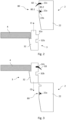
- Figs. 2 and 3 illustrate the relative positions of the sash side member 32 relative to the side member 22 of the stationary frame 2 above and below, respectively, the hinge axis ⁇ , as stylised figures
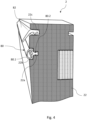
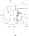
- Fig. 4 shows a rendering of the frame side member 22 when it is not interacting with the corresponding sash side member 32, with the sealing element 80 in its deflated state
- Fig. 5 a rendering with the sash side member 32 interacting with frame side member 22, corresponding to a closed position of the roof window when the sash plane is substantially parallel to the frame plane and the sealing element 80 is in its inflated state.
- Figs. 2 to 5 will be described jointly.
- Fig. 2 illustrates a sealing element 80 which in the embodiment shown is arranged on the frame 2. It is also conceivable to place the sealing element on the sash 3 or sealing elements on both the sash and the frame.
- the sealing element 80 is made from a flexible material and comprises a substantially tubular hollow profile 80.1 configured to assume an inflated and a deflated state.
- the inflated state is obtained by filling the hollow profile 80.1 with a fluid in the closure position of the ventilation flap 35 and the deflated state is obtained by release of the fluid in an open position of the operating element, here the ventilation flap 35.
- the release of the fluid comprises situations in which the fluid is simply discharged by allowing the fluid to flow out of the hollow profile 80.1 and active emptying by for instance suction.
- the sealing element 80 seals a gap between the sash 3 and the frame 2 when the hollow profile 80.1 is in its inflated state and is filled with the fluid.
- the sealing element 80 is arranged in a groove 22a extending in the longitudinal direction of not only the shown side member 22 of the frame, but also in the top member 21, the bottom member 24 and the other side member 23 such that the sealing element 80 forms a coherent structure along an inner face of the frame 2 and the hollow profile 80.1 of the sealing element 80 a coherent passageway or cavity configured to be filled with a liquid in order for the sealing element 80 to assume its inflated state.
- the sealing element 80 placed on the inner face of each of the top member 21, bottom member 24 and two side members 22, 23 of the frame 2 faces an outer face of each of the top member 31, bottom member 34 and two side members 32, 33 of the sash 3.
- the sealing element 80 comprises a fastening portion 80.2 and each frame member, here represented by side member 22, comprises a longitudinal groove 22a receiving said fastening portion 80.2.
- the frame 2 and/or the sash 3 may comprise further gaskets, here in the form of a striking bead gasket 82 provided in an exterior groove 22c on the frame 2, and a striking bead gasket 83 provided in an exterior groove 32c on the sash 3, cf. also the schematic overview of the gaskets in Fig. 6 , to provide a two-level sealing.
- the striking bead gaskets 82, 83 are provided at an exterior side of the gap between the sash 3 and the frame 2.
- the groove 22a comprises a stepped groove opening 22b which has such dimensions that that the sealing element 80 is able to be accommodated substantially in its entirety in the groove 22a and in the stepped groove opening 22b in the deflated state of the sealing element 80.
- the fastening portion 80.2 is connected to or integral with the hollow profile 80.1 and should have sufficient integrity to be insertable into and retained within the groove 22a.
- the fastening portion 80.2 and the hollow profile 80.1 may be co-moulded or co-extruded of the same or different materials.
- the opposing sash 3 here comprises a counter-profile having a shape suitable for fitting the sealing element 80 filled with the fluid. From Fig. 5 it clearly emerges that while the striking bead gasket 82 has performed a movement in the height direction of the frame side member 22, the inflatable sealing element 80 has simply been expanded from its deflated state to its inflated state to provide suitable contact with the counter-profile on the sash side member 32.
- such counter-profile comprises a recess 32b.
- each sash side member 32 is provided with an abutment portion 32a at or near an exterior side of the sash side member 32, 33, in the upper part of the sash 2, from a position at the hinge axis ⁇ and to the top member (31) of the sash (3), to interact with the frame-side striking bead gasket 82 in the closed position of the sash 3 in the exterior groove 22c.
- the substantially tubular hollow profile 80.1 of the sealing element 80 has a wall thickness which is significantly smaller than other dimensions of the sealing element.
- the wall thickness may be provided in the range of 0.1 to 2 mm, and the transverse thickness in the inflated state may be in the range 5 to 14 mm.
- the sealing element 80 is made from a material having a Shore A hardness of 50 A to 60 A.
- the pressure in the sealing element 80 filled with the fluid typically does not exceed 1 bar. The person skilled in the art will select a suitable filling rate and pressure to allow sufficient sealing when the hollow profile 80.1 in its inflated state.
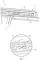
- Fig. 7 the top part of the frame 2 is shown with a pressure source 85 configured to provide the fluid to the hollow profile 80.1 of the sealing element 80.
- the sealing element 80 is functionally connected to a piston 86 connected to the pressure source 85 in that the piston 86 is configured to release the fluid from the hollow profile 80.1 of the sealing element 80 in the open position of the ventilation flap 35.
- a manometer 87 and a control unit 88 are provided to ensure appropriate filling of fluid into the hollow profile 80.1 of the sealing element 80.
- the fluid is a gas, preferably air.
- a suitable valve assembly may also be included to allow for the required filling and emptying of the hollow profile 80.1 of the sealing element 80.
- Fig. 9 shows a roof window system 1 in an alternative embodiment. Elements having the same or analogous function as in the above-described embodiment carry the same reference numerals. Only differences will be described in detail.
- the roof window of this roof window system 1 is a so-called top-hung roof window which pivots for cleaning, i.e. during normal use, the sash 3 is rotated about a hinge axis ⁇ at the top of the roof window, and during cleaning rotated about hinge axis ⁇ , substantially as described in the above embodiment.
- Such a window is shown and described in further detail in Applicant's European patent No. 0 733 146 B1 , the contents of which are hereby incorporated by reference.
- the sash structure is connected with an intermediate frame with frame arms, which in the closed position of the roof window are positioned between the upper parts of the side members of the frame and sash, and which during normal use of the window as a top-hung window follow the sash side members.
- the operating element of the roof window system 1 is here provided as a handle 36 on the sash bottom member 34.
- the roof window system 1 also comprises a ventilation flap 35, which may either function as an additional operating member, that is, being able to assume an opening position, or provide ventilation only in an open position as described in the above.
- the sealing element 80 of flexible material and capable of assuming an inflated state and a deflated state is here provided on the sash 3.
- the activation of the inflated state is here carried out by setting the handle 36 in the closure position when the sash 3 is closed relative to the frame 2.
- the pressure source comprises a pump assembly 84 comprising a pump and a set of valves to allow inflation and deflation of the hollow profile 80.1 of the sealing element 80.
- the pump may be powered by a rechargeable battery (not shown) which may be connected to one or more solar panels (not shown) facing the exterior of the roof window.
- sealing elements including gaskets may be included as well, but are not indicated.
Landscapes
- Engineering & Computer Science (AREA)
- Civil Engineering (AREA)
- Structural Engineering (AREA)
- Architecture (AREA)
- Specific Sealing Or Ventilating Devices For Doors And Windows (AREA)
Abstract
A roof window system (1) comprising of a frame (2) with a top member (21), a bottom member (24), two side members (22, 23), an operating element and a sealing element (80) with a tubular hollow profile (80.1). The sealing element (80) is made from a flexible material; thus the hollow profile (80.1) can assume an inflated or a deflated state by adding fluid via a pressure source. By positioning the operating element in a closure or an opening position, the hollow profile can become inflated or deflated, respectively, and improved sealing, insulation and/or sound dampening properties are achieved.
Description
- The present invention relates to a roof window comprising a frame with a top member, a bottom member and two side members, and a pane-carrying sash placed within the frame and having a top member, a bottom member and two side members, said sash comprising an operating element on the sash top member or the sash bottom member and configured to assume an opening position and a closure position to provide opening and closure, respectively, of the sash relative to the frame, and a set of sealing elements comprising at least one sealing element arranged on the frame or the sash. The invention furthermore relates to a method of sealing a roof window.
- Roof windows have been known for years, and the presence of such roof windows in roof structures of buildings have greatly improved light intake. Such roof windows are operated, i.e. opened and closed, by providing an operating element in the form of a handle or handle bar, e.g. an elongate bar, fixed to a flap rotatably connected to the sash and a locking mechanism, e.g. a lock casing or striking plate placed on the frame. The operation of the operating element may be carried out manually or by semi- or fully automatic operating means, comprising for instance a chain operator. Such roof windows are also quite often provided with a ventilation arrangement, e.g. an opening for ventilation either though the frame or the sash and said opening is provided with means for regulation of the air through the opening. During exposure to different weather conditions, interior portions of the roof windows are protected by coverings elements that are placed and fastened to the exterior surface of the roof window, i.e. the frame and the sash.
- Traditionally, roof windows which pivot around a centre hinge axis have previously been provided with a striking bead gasket on the sash and frame, such that the sash striking bead gasket is only mounted on the bottom and side members of the sash and only up to the hinges, and conversely, on the top and side members of the frame and only down to the hinges. This particular configuration is due to the fact that the top part of the sash moves inwards, i.e. to the interior in the room of the building in which the roof window is installed, and the bottom of the sash outwards in pivoting roof windows.
- In general, it is desired to keep mutually facing sides of the frame and sides in roof windows as close together as possible in the closed position of the sash to limit the size of the spacing or gap between the frame and sash in order to minimise heat loss, draught, noise etc. Combined with the fact that it is also a wish to keep the frame and sash members as slender as possible and with minimal abutment surfaces perpendicular to the directions of opening and closing while at the same time allowing for smooth operation, closing of the spacing between sash and frame in roof windows poses particular challenges.
- While appropriate positioning of gaskets has been known to provide adequate closure of the spacing, or gap, between the frame and sash, modern days' roof windows are typically provided with an additional sealing element to provide improved sealing, insulation and/or sound dampening.
- One example of such a roof window is shown and described in Applicant's European Patent No.
EP 2 738 339 B1 . The configuration with sealing in two levels provides for excellent sealing, insulating and sound dampening. However, there is still room for improvement. - It is an object of the present invention to provide a roof window with improved sealing, insulation and/or sound dampening properties, and which at the same time offers facilitated operation.
- In a first aspect, this and further objects are achieved by means of a roof window system of the kind mentioned in the introduction, which is furthermore characterised in that at least one sealing element of said set is made from a flexible material and comprises a substantially tubular hollow profile, the hollow profile being configured to assume an inflated state and a deflated state, the inflated state being obtained by filling with a fluid in the closure position of the operating element and the deflated state being obtained by release of the fluid in the opening position of the operating element, and that the at least one sealing element seals a gap between the sash and the frame when the hollow profile is in its inflated state and is filled with the fluid.
- By providing a roof window system with the above characteristics an improvement of the sealing and insulation between the frame and the sash are provided, just as an improved sound dampening in the closed position of the roof window is achieved. In this way, it is possible to perform opening and closing of the sash relative to the frame while the hollow profile of the inflatable sealing element is in its deflated state. In turn, this entails that the frictional resistance exerted by the sealing element is reduced during the movement of the sash relative to the frame, and that the risk of damaging the sealing element is reduced or eliminated. This has shown to not only facilitate operation but also increase the lifetime of the components involved. It is noted that the term "deflated" should be interpreted to encompass states in which the fluid has been simply released from the hollow profile, and in which the fluid has been actively discharged, i.e. emptied by active suction.
- Alternatively, or additionally, the sealing element may be provided with larger transverse dimensions than what would have otherwise been possible. While the sash may thus pass the inflatable sealing element substantially unhindered when the hollow profile of the sealing element is in its deflated state, in those cases where the sealing element is positioned on the frame, the hollow profile - when filled with a fluid to assume its inflated state - is able to bridge the gap formed between the frame and the sash in the closed position of the roof window system. Correspondingly, if the inflatable sealing element is provided on the sash, the sash including the deflated sealing element is able to assume the closed position of the roof window system without risking that the sealing element snags on or is dragged along the frame during the closing movement.
- Since the inflatable sealing element is only filled with fluid once the sash is a position close to the frame and the operating element is brought to its closure position, operation of the roof window is not hindered during the closing movement and the otherwise force-requiring task of pulling the sash tight and at the same time moving the operating element to its closure position in prior art roof windows is substantially eliminated.
- In a presently preferred embodiment, the sealing element is at least partially arranged in a groove extending in the longitudinal direction of the top member, the bottom member and the side members of the frame or the sash. In this way, it is possible to form a coherent tubular passageway in the gap, along the outer periphery of the sash and/or the inner periphery of the frame. The sealing element may be placed either on the frame or on the sash, or conceivably on both of the sash and the frame, to provide optimum flexibility in the configuration. The groove may comprise a stepped groove opening more preferably such that the sealing element is able to be accommodated substantially in its entirety in the groove and optionally in the stepped groove opening in the deflated state of the sealing element. By forming the groove with an enlarged groove opening, or alternatively by forming the groove itself with appropriate dimensions, the deflated sealing element may be accommodated in the groove in its entirety, thus avoiding that any parts of the sealing element protrude from beyond the inner side of the frame or the outer side of the sash.
- In a further development of the presently preferred embodiment, the sealing element comprises a fastening portion connected to or integral with the hollow profile. In this way, the hollow profile and the fastening portion may be provided with different properties and even from different materials. The fastening portion is preferably insertable into said groove extending in the longitudinal direction of the top member, the bottom member and the side members of the frame or the sash. By this configuration, as safe retention of the inflatable sealing element is obtained. The fastening portion and the hollow profile may for instance be co-moulded or co-extruded of the same or different materials.
- Since the inflatable sealing element does not need to provide the flexibility and resilience needed by the material itself, but through the intermediate of the hollow profile, medium-soft or even medium-hard materials may be selected. It is preferred that the sealing element is made from a material having a Shore A hardness of 50 A to 60 A. This is for instance achievable by most rubber materials.
- The dimensions of sealing element and in particular of the substantially tubular hollow profile may be chosen in accordance with other components of the roof window system. Suitable values have proven to include a wall thickness of 0.1 to 2 mm and a transverse thickness in the inflated state of 5 to 15 mm. Such values provide a combination of dimensions suitable for providing satisfactory sealing of the sealing element in the inflated state yet allowing deformation or collapse when deflated.
- The inflatable sealing element could in principle be brought to seal against any surface in the closure position of the operating element. However, in one presently preferred embodiment, the opposing sash or frame comprises a counter-profile having a shape suitable for fitting the sealing element in its inflated state, said counter-profile preferably comprising a recess. This provides for optimum utilisation of the inflated state of the sealing element, thus bridging the gap between the frame and sash substantially completely.
- In a further presently preferred embodiment, the sealing element is placed on an inner face of the each of the top member, bottom member and two side members of the frame. Placing the inflatable sealing element provides for a number of advantages; the frame is stationary relative to the roof structure and any wiring required to operate either the roof window itself, any accessories such as roller blinds etc, or the assembly coupled to the inflatable sealing element is easily connected to the mains power of the building. The sealing element is preferably arranged in a groove, optionally with a stepped groove opening, at an interior side of the gap between the sash and the frame. In this way, the sealing element offers a last line of defence, so to say, against any draught, precipitation, or sound from entering the room of the building from the exterior surroundings.
- In a particularly advantageous embodiment, the frame and/or sash further comprises a striking bead gasket to provide a two-level sealing, preferably arranged in a groove in members of the frame and/or sash. In this way, the striking bead gasket provides one sealing plane, which also ensures some insulating and sound-dampening properties, and the inflatable sealing element adds an additional layer.
- In a preferred further development of the above embodiments, the at least one striking bead gasket is provided at an exterior side of the gap between the sash and the frame. That is, the striking bead gaskets provides an exterior weather and sound barrier when the roof window is closed, and the inflatable sealing element forms a barrier towards the interior.
- The principles underlying the invention may be applied to any type of roof window but is particularly applicable in pivoting roof windows, in which the sash is pivotable around a hinge axis, said hinge axis being preferably positioned substantially centrally in the longitudinal direction of the side members of the sash and frame. Due to the fact that the top part of the sash moves inwards and the bottom of the sash outwards, the gaskets have traditionally been placed alternatively on the frame and the sash above and below, respectively, the hinge axis. With the present embodiment, it is possible to place the inflatable sealing element as a continuous sealing element on the sash and/or the frame. Configurations in which the inflatable sealing element forms a U-shape as with traditional sealing and placed on the frame or the sash are of course also conceivable.
- In a further development of embodiments of pivoting roof windows having also a striking bead gasket, an inner face of each sash side member is provided with an abutment portion at or near an exterior side of the sash side member, at least from a position at the hinge axis and to the top member of the sash, and each frame side member is provided with an exterior groove to accommodate one frame-side striking bead gasket, the abutment portion of the sash side member being configured to interact with the frame-side striking bead gasket in the closed position of the sash.
- In one embodiment, the operating element to provide opening and closure of the sash relative to the frame is a ventilation flap rotatably connected with the sash top member and providing ventilation through an opening in the sash top member in an open position of the ventilation flap. Such a ventilation flap is present in roof windows on the market and operation thereof is logical and well-known. As an alternative, a handle traditionally positioned at the bottom of top-hung roof windows may function as an operating element.
- In a presently preferred embodiment, the sealing element is in fluid communication with a pressure source, the pressure source being configured to provide the fluid to fill the hollow profile of the sealing element in the closure position of the operating element, wherein said operating element may be a ventilation flap pivotally hinged to the sash and providing ventilation through ventilation openings in the sash when the flap is in its open position. While the fluid to fill the hollow profile of the sealing element could in principle be introduced by any suitable means, a pressure source is a reliable means of obtaining a controlled inflation and deflation. It has been recognised that the invention functions well also with limited pressure levels, and hence a pressure in the sealing element filled with the fluid may preferably not exceed 1 bar. The fluid may comprise a gas such as air which is readily accessible.
- In a further development of the above-mentioned embodiments, the sealing element is functionally connected to a piston, the piston being connected to the pressure source and configured to release the fluid from the hollow profile of the sealing element in the open position of the ventilation flap. Thus, activation and deactivation of the inflatable sealing element is made particularly logical and easy. The piston may be arranged in the ventilation flap and the piston may be actuated by the movement of the ventilation flap into the closed and open position, respectively.
- In a still further development of these embodiments, the sealing element is coupled to a manometer, and a control unit is connected to the manometer and to the pressure source.
- In an alternative, presently preferred embodiment, the pressure source comprises a pump assembly comprising a pump and a set of valves to allow inflation and deflation of the hollow profile of the sealing element. Suitable pumps of a limited size, yet capable of providing repeated inflation have been increasingly popular in recent years, and commercially available models suitable for cycling or hiking exist at competitive prices. Since the gap between the sash and the frame of roof windows is of a limited size, the volume of fluid to be pumped into the sealing
element 80 is consequently limited. Typical values of the total inflated volume of the hollow profile of a sealing element for even relatively large roof windows are below that of an average bicycle tyre, and the required pressure to keep the sealing effect satisfactory a fraction of that required for bicycle tyres. The pump may preferably be powered by a rechargeable battery, the battery being more preferably connected to one or more solar panels facing the exterior of the roof window. In this way, the roof window including operation of the inflatable sealing element is made self-sufficient and may function as a stand-alone unit without requiring connection to the mains power supply of the housing. - In a second aspect, a method of sealing a roof window is provided. The method comprises the steps of: arranging the at least one sealing element on the frame or the sash of the roof window, bringing the sash from an open position in which a sash plane forms an angle to a frame plane to a position in which the sash plane is substantially parallel to the frame plane, placing the operating element in its closure position, thereby filling the hollow profile and bringing the hollow profile to its inflated state to seal the gap between the sash and the frame.
- Other embodiments and advantages will appear from the detailed description and remaining dependent claims.
- It is noted that the invention relates to all possible combinations of features recited in the claims.
- The present invention will now be described in more detail with reference to the appended drawings showing embodiment(s) of the invention.
-
Fig. 1 is a perspective view of a roof window system in an embodiment of the invention; -
Figs. 2 and 3 are schematic sectional views substantially corresponding to sections along the lines II-II and III-III, respectively, ofFig. 1 , showing a sealing element of an embodiment of the invention partially embedded in a frame of the roof window; -
Fig. 4 is a partial perspective view, sectional view of a side frame member substantially corresponding to a section along the line II-II ofFig. 1 ; -
Fig. 5 is a partial perspective, sectional view, substantially corresponding toFig. 4 , but also showing a sash of the roof window in an embodiment of the invention; -
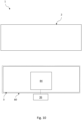
Fig. 6 is a principal sketch of the positioning of a sealing element and additional gaskets in a roof window system in an embodiment of the invention; -
Fig. 7 is a partial perspective view of the top of a roof window system in an embodiment of the invention, including a break-out detail view; -
Fig. 8 is a schematic view of the roof window system in an embodiment of the invention; -
Fig. 9 is a perspective view of a roof window system in an alternative embodiment of the invention; and -
Fig. 10 is a schematic view of the roof window system in an embodiment of the invention; and. - In the following detailed description, a preferred embodiment of the present invention will be described. However, it is to be understood that features of the different embodiments are exchangeable between the embodiments and may be combined in different ways, unless anything else is specifically indicated. It may also be noted that, for the sake of clarity, the dimensions of certain components illustrated in the drawings may differ from the corresponding dimensions in real-life implementations.
- It is noted that terms such as "up", "down", "left-hand", "right-hand", "exterior", "interior", "outer", "inner" are relative and refers to the viewpoint in question. In general, when referred to an exterior side, this relates to a side of a roof window in the mounted condition facing the outdoors or external side of the building. Conversely, an interior side refers to a side facing the internal side of the building, i.e. typically a subjacent room including any light shaft. Terms such as "outwards" and "inwards" are directions generally perpendicular to an interior-exterior direction, taking as its base point a centre of the roof window. A longitudinal direction is, if nothing else is mentioned, longitudinal along the length of a frame member of the roof window. It is to be understood that the arrangement shown in a horizontal orientation is not the normal orientation as the roof window is installed in an inclined roof.
- In the figures of the drawing, embodiments of a roof window according to the invention is shown.
- In the figures, the sizes of layers and regions are exaggerated for illustrative purposes and, thus, are intended to illustrate the general structures of embodiments of the present invention. Like reference numerals refer to like elements throughout, even though they may not be identical.
- Referring initially to
Fig. 1 , aroof window system 1 comprises a roof window with aframe 2 with atop member 21, abottom member 24 and twoside members Fig. 1 further shows asash 3 carrying apane 4 and placed within theframe 2. Thesash 3 has atop member 31, abottom member 34 and twoside members - The
roof window system 1 is provided with an operating element to provide opening and closure of thesash 3 relative to theframe 2. In the embodiment shown inFigs 1 to 8 , thesash 3 comprises aventilation flap 35 constituting the operating element and being rotatably connected with thesash top member 31 and configured to provide ventilation through an opening in thesash top member 31 in an open position of theventilation flap 35. This is particularly relevant in a closed position of theroof window system 1, i.e. when thesash 3 is placed with a sash plane parallel with a frame plane. In the position shown inFig. 1 , theroof window system 1 is open, in that thesash 3 assumes an angle relative to theframe 2. This is achieved in that the pane-carryingsash 3 is connected to the frame via a set ofhinges 5 connected to theside members sash 3 and to theside members frame 2. The set ofhinges 5 make it possible for the pane-carryingsash 3 to pivot around a hinge axis α. During the pivoting movement, the lower, or bottom, parts of thesash 3, including thebottom member 34, swing outwards relative to a plane parallel to the frame plane, and the upper, or top, parts of thesash 3, including thetop member 31, swing inwards relative to the plane parallel to the frame plane. The respective closing directions are indicated by arrows Ct and Cb. - Typically, the
ventilation flap 35 is able to assume the following positions: A closure position corresponding to the closed position of theroof window system 1, and an open position, in which it is able to provide ventilation through said opening in thesash top member 31. In the specific embodiment, in which theventilation flap 35 also constitutes the operating member, theventilation flap 35 is also able to assume an opening position, in which the locking mechanism (not shown) between thesash 3 andframe 2 is released. In a manner known per se, theventilation flap 35 thus has a dual function as an operating and locking assembly, by which it is possible to open, close and lock thesash 3 relative to theframe 1 by means of a locking mechanism comprising one or more striking plates (not shown in detail) on thetop member 21 of theframe 2 interacting with latches on theventilation flap 35. - In other embodiments, the operating element may be placed at the bottom of the
sash 3 as will be described further below, or the operating element may function as a valve placed either in the top or the bottom of thesash 3 orframe 2. -
Figs. 2 and 3 illustrate the relative positions of thesash side member 32 relative to theside member 22 of thestationary frame 2 above and below, respectively, the hinge axis α, as stylised figures, whereasFig. 4 shows a rendering of theframe side member 22 when it is not interacting with the correspondingsash side member 32, with the sealingelement 80 in its deflated state, andFig. 5 a rendering with thesash side member 32 interacting withframe side member 22, corresponding to a closed position of the roof window when the sash plane is substantially parallel to the frame plane and the sealingelement 80 is in its inflated state.Figs. 2 to 5 will be described jointly. -
Fig. 2 illustrates a sealingelement 80 which in the embodiment shown is arranged on theframe 2. It is also conceivable to place the sealing element on thesash 3 or sealing elements on both the sash and the frame. - The sealing
element 80 is made from a flexible material and comprises a substantially tubular hollow profile 80.1 configured to assume an inflated and a deflated state. As will be described in further detail below, the inflated state is obtained by filling the hollow profile 80.1 with a fluid in the closure position of theventilation flap 35 and the deflated state is obtained by release of the fluid in an open position of the operating element, here theventilation flap 35. The release of the fluid comprises situations in which the fluid is simply discharged by allowing the fluid to flow out of the hollow profile 80.1 and active emptying by for instance suction. - The sealing
element 80 seals a gap between thesash 3 and theframe 2 when the hollow profile 80.1 is in its inflated state and is filled with the fluid. In the embodiment shown, the sealingelement 80 is arranged in agroove 22a extending in the longitudinal direction of not only the shownside member 22 of the frame, but also in thetop member 21, thebottom member 24 and theother side member 23 such that the sealingelement 80 forms a coherent structure along an inner face of theframe 2 and the hollow profile 80.1 of the sealing element 80 a coherent passageway or cavity configured to be filled with a liquid in order for the sealingelement 80 to assume its inflated state. - The sealing
element 80 placed on the inner face of each of thetop member 21,bottom member 24 and twoside members frame 2 faces an outer face of each of thetop member 31,bottom member 34 and twoside members sash 3. In the embodiment shown, the sealingelement 80 comprises a fastening portion 80.2 and each frame member, here represented byside member 22, comprises alongitudinal groove 22a receiving said fastening portion 80.2. In addition to the sealingelement 80 embedded in theframe 2, or alternatively in thesash 3, theframe 2 and/or thesash 3 may comprise further gaskets, here in the form of astriking bead gasket 82 provided in anexterior groove 22c on theframe 2, and astriking bead gasket 83 provided in anexterior groove 32c on thesash 3, cf. also the schematic overview of the gaskets inFig. 6 , to provide a two-level sealing. Here, thestriking bead gaskets sash 3 and theframe 2. - In the embodiment shown, the
groove 22a comprises a steppedgroove opening 22b which has such dimensions that that the sealingelement 80 is able to be accommodated substantially in its entirety in thegroove 22a and in the steppedgroove opening 22b in the deflated state of the sealingelement 80. - The fastening portion 80.2 is connected to or integral with the hollow profile 80.1 and should have sufficient integrity to be insertable into and retained within the
groove 22a. The fastening portion 80.2 and the hollow profile 80.1 may be co-moulded or co-extruded of the same or different materials. - To counter-support the sealing
element 80, i.e. to provide a suitable abutment surface, the opposingsash 3 here comprises a counter-profile having a shape suitable for fitting the sealingelement 80 filled with the fluid. FromFig. 5 it clearly emerges that while thestriking bead gasket 82 has performed a movement in the height direction of theframe side member 22, theinflatable sealing element 80 has simply been expanded from its deflated state to its inflated state to provide suitable contact with the counter-profile on thesash side member 32. - In the embodiment shown, such counter-profile comprises a
recess 32b. - Further details shown in
Fig. 2 includes that an inner face of eachsash side member 32 is provided with anabutment portion 32a at or near an exterior side of thesash side member sash 2, from a position at the hinge axis α and to the top member (31) of the sash (3), to interact with the frame-sidestriking bead gasket 82 in the closed position of thesash 3 in theexterior groove 22c. - In one exemplary embodiment, the substantially tubular hollow profile 80.1 of the sealing
element 80 has a wall thickness which is significantly smaller than other dimensions of the sealing element. For instance, the wall thickness may be provided in the range of 0.1 to 2 mm, and the transverse thickness in the inflated state may be in therange 5 to 14 mm. The sealingelement 80 is made from a material having a Shore A hardness of 50 A to 60 A. The pressure in the sealingelement 80 filled with the fluid typically does not exceed 1 bar. The person skilled in the art will select a suitable filling rate and pressure to allow sufficient sealing when the hollow profile 80.1 in its inflated state. - In
Fig. 7 , the top part of theframe 2 is shown with apressure source 85 configured to provide the fluid to the hollow profile 80.1 of the sealingelement 80. Referring now also to the schematic overview ofFig. 8 , the sealingelement 80 is functionally connected to apiston 86 connected to thepressure source 85 in that thepiston 86 is configured to release the fluid from the hollow profile 80.1 of the sealingelement 80 in the open position of theventilation flap 35. Amanometer 87 and acontrol unit 88 are provided to ensure appropriate filling of fluid into the hollow profile 80.1 of the sealingelement 80. The fluid is a gas, preferably air. A suitable valve assembly may also be included to allow for the required filling and emptying of the hollow profile 80.1 of the sealingelement 80. -
Fig. 9 shows aroof window system 1 in an alternative embodiment. Elements having the same or analogous function as in the above-described embodiment carry the same reference numerals. Only differences will be described in detail. The roof window of thisroof window system 1 is a so-called top-hung roof window which pivots for cleaning, i.e. during normal use, thesash 3 is rotated about a hinge axis β at the top of the roof window, and during cleaning rotated about hinge axis α, substantially as described in the above embodiment. Such a window is shown and described in further detail in Applicant'sEuropean patent No. 0 733 146 B1 , the contents of which are hereby incorporated by reference. To make it possible to pivot the window sash approximately 180° to a convenient cleaning position, the sash structure is connected with an intermediate frame with frame arms, which in the closed position of the roof window are positioned between the upper parts of the side members of the frame and sash, and which during normal use of the window as a top-hung window follow the sash side members. - The operating element of the
roof window system 1 is here provided as ahandle 36 on thesash bottom member 34. Theroof window system 1 also comprises aventilation flap 35, which may either function as an additional operating member, that is, being able to assume an opening position, or provide ventilation only in an open position as described in the above. - The sealing
element 80 of flexible material and capable of assuming an inflated state and a deflated state is here provided on thesash 3. The activation of the inflated state is here carried out by setting thehandle 36 in the closure position when thesash 3 is closed relative to theframe 2. - An overview of a suitable assembly for a compact accommodation of the means to provide the required functionality is shown in
Fig. 10 , in which the pressure source comprises apump assembly 84 comprising a pump and a set of valves to allow inflation and deflation of the hollow profile 80.1 of the sealingelement 80. The pump may be powered by a rechargeable battery (not shown) which may be connected to one or more solar panels (not shown) facing the exterior of the roof window. - Other sealing elements including gaskets may be included as well, but are not indicated.
- The person skilled in the art realizes that the present invention by no element is limited to the preferred embodiments described above. On the contrary, many modifications and variations are possible within the scope of the appended claims.
- Additionally, variations to the disclosed embodiments can be understood and effected by the skilled person in practicing the claimed invention, from a study of the drawings, the disclosure, and the appended claims. In the claims, the word "comprising" does not exclude other elements or steps, and the indefinite article "a" or "an" does not exclude a plurality. The mere fact that certain measures are recited in mutually different dependent claims does not indicate that a combination of these measured cannot be used to advantage.
-
- 1
- roof window system
- 2
- frame
21 top member
22 side member
22a groove
22b stepped groove opening
22c exterior groove
23 side member
24 bottom member - 3
- sash
31 top member
32 side member
32a abutment portion
32b recess
32c exterior groove
33 side member
34 bottom member
35 ventilation flap
36 handle - 4
- pane
- 5
- hinge
- 80
- sealing element
80.1 tubular hollow profile
80.2 fastening portion of sealing element - 82
- striking bead gasket (frame)
- 83
- striking bead gasket (sash)
- 84
- pump assembly
- 85
- pressure source
- 86
- piston
- 87
- manometer
- 88
- control unit
- α
- hinge axis
- β
- hinge axis
- Ct
- closing direction, top
- Cb
- closing direction, bottom
Claims (17)
- A roof window system (1), comprising:a frame (2) with a top member (21), a bottom member (24) and two side members (22, 23), anda pane-carrying sash (3) placed within the frame (2) and having a top member (31), a bottom member (34) and two side members (32, 33), said sash (3) comprising an operating element (35, 36) on the sash top member (31) or the sash bottom member (34) and configured to assume an opening position and a closure position to provide opening and closure, respectively, of the sash (3) relative to the frame (2), anda set of sealing elements comprising at least one sealing element (80, 82, 83) arranged on the frame (2) or the sash (3),characterised in thatat least one sealing element (80) of said set is made from a flexible material and comprises a substantially tubular hollow profile (80.1), the hollow profile (80.1) being configured to assume an inflated state and a deflated state, the inflated state being obtained by filling with a fluid in the closure position of the operating element (35; 36) and the deflated state being obtained by release of the fluid in the opening position of the operating element (35; 36),and that the at least one sealing element (80) seals a gap between the sash (3) and the frame (2) when the hollow profile (80.1) is in its inflated state and is filled with the fluid.
- A roof window system (1) according to claim 1, wherein the sealing element (80) is at least partially arranged in a groove (22a) extending in the longitudinal direction of the top member (21), the bottom member (24) and the side members (22, 23) of the frame (2) or the sash (3), the groove (22a) preferably comprising a stepped groove opening (22b), more preferably such that the sealing element (80) is able to be accommodated substantially in its entirety in the groove (22a) and optionally in the stepped groove opening (22b) in the deflated state of the sealing element (80).
- A roof window system (1) according to claim 2, wherein the sealing element (80) comprises a fastening portion (80.2) connected to or integral with the hollow profile (80.1), the fastening portion (80.2) being preferably insertable into said groove (22a) extending in the longitudinal direction of the top member (21), the bottom member (24) and the side members (22, 23) of the frame (2) or the sash (3), the fastening portion (80.2) and the hollow profile (80.1) being preferably co-moulded or co-extruded of the same or different materials.
- A roof window system (1) according to any one of the preceding claims, wherein the sealing element (80) is made from a material having a Shore A hardness of 50 A to 60 A.
- A roof window system (1) according to any one of the preceding claims, wherein the substantially tubular hollow profile (80.1) of the sealing element (80) has a wall thickness of 0.1 to 2 mm, and wherein the substantially tubular hollow profile (80.1) has a transverse thickness in the inflated state of 5 to 15 mm.
- A roof window system (1) according to any one of the preceding claims, wherein the opposing sash or frame comprises a counter-profile having a shape suitable for fitting the sealing element (80) in its inflated state, said counter-profile preferably comprising a recess (32b).
- A roof window system (1) according to any one of the preceding claims, wherein the sealing element (80) is placed on an inner face of the each of the top member (21), bottom member (24) and two side members (22, 23) of the frame (2), preferably in a groove (22a), optionally with a stepped groove opening (22b), at an interior side of the gap between the sash (3) and the frame (2).
- A roof window system (1) according to any one of the preceding claims, wherein the frame (2) and/or sash (3) further comprises at least one striking bead gasket (82, 83) to provide a two-level sealing, preferably arranged in a groove (22c, 32c) in members of the frame (2) and/or sash (3).
- A roof window system (1) according to claims 7 and 8, wherein the at least one striking bead gasket (82, 83) is provided at an exterior side of the gap between the sash (3) and the frame (2).
- A roof window system (1) according to any one of the preceding claims, wherein the roof window is a pivoting roof window, in which the sash (3) is pivotable around a hinge axis (α), said hinge axis (α) being preferably positioned substantially centrally in the longitudinal direction of the side members of the sash and frame.
- A roof window system (1) according to claims 9 and 10, wherein an inner face of each sash side member (32, 33) is provided with an abutment portion (32a) at or near an exterior side of the sash side member (32, 33), at least from a position at the hinge axis (α) and to the top member (31) of the sash (3), and each frame side member (22, 23) is provided with an exterior groove (22c) to accommodate one frame-side striking bead gasket (82), the abutment portion (32) of the sash side member (32) being configured to interact with the frame-side striking bead gasket (82) in the closed position of the sash (3).
- A roof window system (1) according to any one of the preceding claims, wherein the operating element to provide opening and closure of the sash (3) relative to the frame (2) is a ventilation flap (35) rotatably connected with the sash top member (31) and providing ventilation through an opening in the sash top member (31) in an open position of the ventilation flap (35).
- A roof window system (1) according to any one of the preceding claims, wherein the sealing element (80) is in fluid communication with a pressure source (85), the pressure source (85) being configured to provide the fluid to fill the hollow profile (80.1) of the sealing element (80) in the closure position of the operating element (35; 36), a pressure in the sealing element (80) filled with the fluid preferably not exceeding 1 bar, the fluid more preferably comprising a gas such as air.
- A roof window system (1) according to claims 12 and 13, wherein the sealing element (80) is functionally connected to a piston (86), the piston (86) being connected to the pressure source (85) and configured to activate inflation of the sealing element (80) in the closure position and to release the fluid from the hollow profile (80.1) of the sealing element (80) in the opening position of the ventilation flap (35), the piston (86) being preferably arranged in the ventilation flap (35), the piston (86) being more preferably actuated by the movement of the ventilation flap (35) into the closed and open position, respectively.
- A roof window system (1) according to any one of claims 13 and 14, wherein the sealing element (80) is coupled to a manometer (87), and wherein a control unit (88) is connected to the manometer (87) and to the pressure source (85).
- A roof window system (1) according to any one of claims 13 to 15, wherein the pressure source comprises a pump assembly (84) comprising a pump and a set of valves to allow inflation and deflation of the hollow profile (80.1) of the sealing element (80), said pump being preferably powered by a rechargeable battery, the battery being more preferably connected to one or more solar panels facing the exterior of the roof window.
- A method of sealing a roof window (1) according to any one of claims 1 to 16, comprising the steps of:arranging the at least one sealing element (80) on the frame (2) or the sash (3) of the roof window (1),bringing the sash (3) from an open position in which a sash plane forms an angle to a frame plane to a position in which the sash plane is substantially parallel to the frame plane,placing the operating element (35; 36) in its closure position, thereby filling the hollow profile (80.1) and bringing the hollow profile (80.1) to its inflated state to seal the gap between the sash (3) and the frame (2).
Applications Claiming Priority (1)
| Application Number | Priority Date | Filing Date | Title |
|---|---|---|---|
| DKPA202370105 | 2023-02-24 |
Publications (1)
| Publication Number | Publication Date |
|---|---|
| EP4421262A1 true EP4421262A1 (en) | 2024-08-28 |
Family
ID=92075759
Family Applications (1)
| Application Number | Title | Priority Date | Filing Date |
|---|---|---|---|
| EP24159557.8A Pending EP4421262A1 (en) | 2023-02-24 | 2024-02-26 | A roof window system comprising an inflatable sealing element, and a method of sealing such a roof window |
Country Status (1)
| Country | Link |
|---|---|
| EP (1) | EP4421262A1 (en) |
Citations (4)
| Publication number | Priority date | Publication date | Assignee | Title |
|---|---|---|---|---|
| FR2009490A1 (en) * | 1968-05-28 | 1970-02-06 | Frach Werner | |
| EP0733146B1 (en) | 1993-12-10 | 1997-06-11 | V. Kann Rasmussen Industri A/S | A window, particularly for installation in an inclined roof surface |
| EP2738339B1 (en) | 2012-12-03 | 2017-04-19 | VKR Holding A/S | A window with sound dampening and/or insulating members |
| CN106894713A (en) * | 2015-12-21 | 2017-06-27 | 上海上源建筑科技有限公司 | Nei Kainei leads window |
-
2024
- 2024-02-26 EP EP24159557.8A patent/EP4421262A1/en active Pending
Patent Citations (4)
| Publication number | Priority date | Publication date | Assignee | Title |
|---|---|---|---|---|
| FR2009490A1 (en) * | 1968-05-28 | 1970-02-06 | Frach Werner | |
| EP0733146B1 (en) | 1993-12-10 | 1997-06-11 | V. Kann Rasmussen Industri A/S | A window, particularly for installation in an inclined roof surface |
| EP2738339B1 (en) | 2012-12-03 | 2017-04-19 | VKR Holding A/S | A window with sound dampening and/or insulating members |
| CN106894713A (en) * | 2015-12-21 | 2017-06-27 | 上海上源建筑科技有限公司 | Nei Kainei leads window |
Similar Documents
| Publication | Publication Date | Title |
|---|---|---|
| CN104508227B (en) | Insulated window assembly | |
| US8381445B2 (en) | Automatically sealing multi panel sliding door assembly | |
| AU2002227283B2 (en) | Overhead garage door | |
| US20090265991A1 (en) | Sash windows | |
| US11060345B2 (en) | Temporary water barrier to prevent flooding through residential and commercial doors | |
| TWI320070B (en) | Improvements to roller shutters | |
| US10443283B2 (en) | Single hung window construction with an upper fixed lite of glass and a movable bottom sash being generally coplanar | |
| US6722082B1 (en) | Window having a hinged weatherstrip | |
| EP4421262A1 (en) | A roof window system comprising an inflatable sealing element, and a method of sealing such a roof window | |
| US10920483B2 (en) | Window seal for preventing water penetration | |
| JP2024506892A (en) | Shutter-type roll-up device with watertight sealing means to seal the opening | |
| CN101827991B (en) | A window, a method for mounting a window, and a set of parts | |
| JP2003129766A (en) | Water sealing device for door | |
| US7052390B2 (en) | Revolving door | |
| CN116771252A (en) | Bridge-cutoff aluminum passive window | |
| JP3810302B2 (en) | Retractable water stop device | |
| KR101030190B1 (en) | System window lock | |
| JPH0428393Y2 (en) | ||
| FR2785014A1 (en) | Sealing system for sealing a wall opening to prevent flooding, comprises a sealing lining mounted on a frame assembly | |
| JPH0711210B2 (en) | Hinge and door opening / closing device using the hinge | |
| KR200355810Y1 (en) | A locking equipment for system window and door | |
| JPH08135302A (en) | Sash | |
| KR101736286B1 (en) | Floodgate | |
| JP7624131B2 (en) | Seal structure of rotating seal body of folding door | |
| KR20110002385U (en) | A projection type roller shutter |
Legal Events
| Date | Code | Title | Description |
|---|---|---|---|
| PUAI | Public reference made under article 153(3) epc to a published international application that has entered the european phase |
Free format text: ORIGINAL CODE: 0009012 |
|
| STAA | Information on the status of an ep patent application or granted ep patent |
Free format text: STATUS: THE APPLICATION HAS BEEN PUBLISHED |
|
| AK | Designated contracting states |
Kind code of ref document: A1 Designated state(s): AL AT BE BG CH CY CZ DE DK EE ES FI FR GB GR HR HU IE IS IT LI LT LU LV MC ME MK MT NL NO PL PT RO RS SE SI SK SM TR |
|
| STAA | Information on the status of an ep patent application or granted ep patent |
Free format text: STATUS: REQUEST FOR EXAMINATION WAS MADE |
|
| 17P | Request for examination filed |
Effective date: 20250218 |