EP4420985B1 - Flugzeugantriebsanordnung mit mindestens einer überdruckvorrichtung und flugzeug mit mindestens einer solchen antriebseinheit - Google Patents
Flugzeugantriebsanordnung mit mindestens einer überdruckvorrichtung und flugzeug mit mindestens einer solchen antriebseinheit Download PDFInfo
- Publication number
- EP4420985B1 EP4420985B1 EP24157877.2A EP24157877A EP4420985B1 EP 4420985 B1 EP4420985 B1 EP 4420985B1 EP 24157877 A EP24157877 A EP 24157877A EP 4420985 B1 EP4420985 B1 EP 4420985B1
- Authority
- EP
- European Patent Office
- Prior art keywords
- door
- pressure relief
- relief device
- propulsion unit
- opening
- Prior art date
- Legal status (The legal status is an assumption and is not a legal conclusion. Google has not performed a legal analysis and makes no representation as to the accuracy of the status listed.)
- Active
Links
Images




Classifications
-
- B—PERFORMING OPERATIONS; TRANSPORTING
- B64—AIRCRAFT; AVIATION; COSMONAUTICS
- B64D—EQUIPMENT FOR FITTING IN OR TO AIRCRAFT; FLIGHT SUITS; PARACHUTES; ARRANGEMENT OR MOUNTING OF POWER PLANTS OR PROPULSION TRANSMISSIONS IN AIRCRAFT
- B64D27/00—Arrangement or mounting of power plants in aircraft; Aircraft characterised by the type or position of power plants
- B64D27/02—Aircraft characterised by the type or position of power plants
- B64D27/24—Aircraft characterised by the type or position of power plants using steam or spring force
-
- B—PERFORMING OPERATIONS; TRANSPORTING
- B64—AIRCRAFT; AVIATION; COSMONAUTICS
- B64C—AEROPLANES; HELICOPTERS
- B64C1/00—Fuselages; Constructional features common to fuselages, wings, stabilising surfaces or the like
- B64C1/14—Windows; Doors; Hatch covers or access panels; Surrounding frame structures; Canopies; Windscreens accessories therefor, e.g. pressure sensors, water deflectors, hinges, seals, handles, latches, windscreen wipers
- B64C1/1407—Doors; surrounding frames
-
- B—PERFORMING OPERATIONS; TRANSPORTING
- B64—AIRCRAFT; AVIATION; COSMONAUTICS
- B64D—EQUIPMENT FOR FITTING IN OR TO AIRCRAFT; FLIGHT SUITS; PARACHUTES; ARRANGEMENT OR MOUNTING OF POWER PLANTS OR PROPULSION TRANSMISSIONS IN AIRCRAFT
- B64D27/00—Arrangement or mounting of power plants in aircraft; Aircraft characterised by the type or position of power plants
- B64D27/02—Aircraft characterised by the type or position of power plants
- B64D27/10—Aircraft characterised by the type or position of power plants of gas-turbine type
- B64D27/12—Aircraft characterised by the type or position of power plants of gas-turbine type within, or attached to, wings
-
- B—PERFORMING OPERATIONS; TRANSPORTING
- B64—AIRCRAFT; AVIATION; COSMONAUTICS
- B64D—EQUIPMENT FOR FITTING IN OR TO AIRCRAFT; FLIGHT SUITS; PARACHUTES; ARRANGEMENT OR MOUNTING OF POWER PLANTS OR PROPULSION TRANSMISSIONS IN AIRCRAFT
- B64D29/00—Power-plant nacelles, fairings or cowlings
-
- B—PERFORMING OPERATIONS; TRANSPORTING
- B64—AIRCRAFT; AVIATION; COSMONAUTICS
- B64D—EQUIPMENT FOR FITTING IN OR TO AIRCRAFT; FLIGHT SUITS; PARACHUTES; ARRANGEMENT OR MOUNTING OF POWER PLANTS OR PROPULSION TRANSMISSIONS IN AIRCRAFT
- B64D29/00—Power-plant nacelles, fairings or cowlings
- B64D29/06—Attaching of nacelles, fairings or cowlings
-
- B—PERFORMING OPERATIONS; TRANSPORTING
- B64—AIRCRAFT; AVIATION; COSMONAUTICS
- B64C—AEROPLANES; HELICOPTERS
- B64C1/00—Fuselages; Constructional features common to fuselages, wings, stabilising surfaces or the like
- B64C1/14—Windows; Doors; Hatch covers or access panels; Surrounding frame structures; Canopies; Windscreens accessories therefor, e.g. pressure sensors, water deflectors, hinges, seals, handles, latches, windscreen wipers
-
- B—PERFORMING OPERATIONS; TRANSPORTING
- B64—AIRCRAFT; AVIATION; COSMONAUTICS
- B64C—AEROPLANES; HELICOPTERS
- B64C1/00—Fuselages; Constructional features common to fuselages, wings, stabilising surfaces or the like
- B64C2001/009—Fuselages; Constructional features common to fuselages, wings, stabilising surfaces or the like comprising decompression panels or valves for pressure equalisation in fuselages or floors
-
- B—PERFORMING OPERATIONS; TRANSPORTING
- B64—AIRCRAFT; AVIATION; COSMONAUTICS
- B64D—EQUIPMENT FOR FITTING IN OR TO AIRCRAFT; FLIGHT SUITS; PARACHUTES; ARRANGEMENT OR MOUNTING OF POWER PLANTS OR PROPULSION TRANSMISSIONS IN AIRCRAFT
- B64D37/00—Arrangements in connection with fuel supply for power plant
- B64D37/02—Tanks
- B64D37/14—Filling or emptying
- B64D37/20—Emptying systems
- B64D37/24—Emptying systems using gas pressure
-
- B—PERFORMING OPERATIONS; TRANSPORTING
- B64—AIRCRAFT; AVIATION; COSMONAUTICS
- B64D—EQUIPMENT FOR FITTING IN OR TO AIRCRAFT; FLIGHT SUITS; PARACHUTES; ARRANGEMENT OR MOUNTING OF POWER PLANTS OR PROPULSION TRANSMISSIONS IN AIRCRAFT
- B64D37/00—Arrangements in connection with fuel supply for power plant
- B64D37/32—Safety measures not otherwise provided for, e.g. preventing explosive conditions
Definitions
- the present application relates to an aircraft propulsion assembly comprising at least one overpressure device as well as to an aircraft comprising at least one such propulsion assembly.
- an aircraft 10 comprises a fuselage 12, wings 14 which extend on either side of the fuselage as well as propulsion assemblies 16 connected to the wings 14 and positioned below the wings 14.
- a propulsion assembly 16 comprises a turboprop 18, a propeller 20 driven in rotation by the turboprop 18 as well as a nacelle 22 in which the turboprop 18 is positioned, the propeller 20 being positioned in front and outside the nacelle 22.
- the turboprop 18 operating on hydrogen the aircraft 10 comprises a hydrogen supply system 24.
- the hydrogen being stored in a cryogenic state, the hydrogen supply system 24 is configured to compress the hydrogen to a very high pressure, vaporize it and then reheat it before supplying the turboprop 18.
- the hydrogen supply system 24 can generate a rapid increase in pressure inside the nacelle 22.
- the nacelle 22 is reinforced. This solution is not satisfactory because it leads to a significant increase in the mass of the nacelle 22.
- the present invention aims to remedy all or part of these drawbacks.
- the invention relates to an aircraft propulsion assembly as claimed in claim 1.
- the patent applications US2020/130811 And US2011/297787 describe the preamble of claim 1.
- the invention also relates to an aircraft comprising at least one such propulsion assembly.
- a propulsion assembly 30 comprises a motor 32, a propeller 34 driven in rotation by the motor 32 as well as a nacelle 36 which forms an aerodynamic fairing around the motor 32, the propeller 34 being positioned outside and at the front of the nacelle 36.
- the motorization 32 comprises an axis of rotation A32 substantially parallel to that of the propeller 34.
- a longitudinal direction is a direction parallel to the axis of rotation A32 of the motor 32.
- a transverse plane is a plane perpendicular to the axis of rotation A32 of the motor 32.
- the concepts front and rear refer to the direction of air flow around the motor 32 in flight, which flows from front to rear.
- an aircraft comprises at least one propulsion assembly 30 positioned under a wing 38 of the aircraft and connected to the latter.
- the invention is not limited to this application or to this positioning for the propulsion assembly 30.
- the propulsion assembly 30 is supplied with fuel by a fuel supply system 40 positioned partly in the nacelle 36.
- the fuel is in gaseous form and the fuel supply system is therefore a gaseous fuel supply system.
- the fuel is in liquid cryogenic form and the fuel supply system 40 is therefore a liquid cryogenic fuel supply system.
- the propulsion assembly operating on hydrogen the fuel supply system 40 comprises at least one element among a high pressure pump, a vaporization system, a heat exchanger, conduits, shut-off valves and buffer tanks.
- a high pressure pump a vaporization system
- a heat exchanger a heat exchanger
- conduits shut-off valves and buffer tanks.
- the invention is not limited to hydrogen as fuel.
- the nacelle 36 comprises a primary structure ensuring, among other things, the absorption of forces as well as a secondary structure, in the form of an aerodynamic fairing 46, supported by the primary structure.
- This fairing 46 comprises a set of juxtaposed walls, each having a face in contact with an air flow when the aircraft is in flight.
- the fairing 46 comprises a central portion 46.1 positioned under the wing 38 and a rear portion 46.2 offset rearwardly relative to a vertical plane passing through the trailing edge 38.1 of the wing 38.
- the fairing 46 does not include any portion offset rearwardly relative to a vertical plane passing through the trailing edge 38.1 of the wing 38.
- the first and second side walls 48.1, 48.2 are substantially symmetrical with respect to a median plane PM (visible on the Figure 4 ), substantially vertical, containing the trailing edge 50.
- the first and second side walls 48.1, 48.2 form, in a transverse plane, an approximately V-shape with a downwardly oriented tip, the trailing edge 50 extending to the central part 46.1 of the fairing 46.
- the trailing edge 50 is substantially vertical and the fairing 46 comprises a lower wall 52' connecting the first and second side walls 48.1, 48.2 to the trailing edge 50.
- the fairing 46 separates an interior zone and an exterior zone, the engine 32 and at least part of the fuel supply system 40 being positioned in the interior zone.
- the propulsion assembly 30 comprises a pressure relief device 54 configured to occupy an inactivated state, when the interior zone has a pressure lower than a given threshold, in which the pressure relief device 54 forms a substantially fluid-tight barrier between the interior and exterior zones, as well as an activated state, when the interior zone has a pressure greater than or equal to the given threshold, in which the pressure relief device 54 allows the interior and exterior zones to communicate.
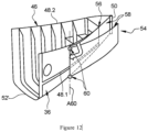
- the fairing 46 comprises first and second side walls 48.1, 48.2 as well as a trailing edge 50 positioned at the rear end of the fairing 46, the side walls 48.1, 48.2 joining at the trailing edge 50.
- the fairing 46 comprises an upper wall 52, positioned in a substantially horizontal plane, connecting the first and second side walls 48.1, 48.2 and extending to the trailing edge 50.
- the pressure relief device 54 comprises at least one opening 56, passing through the fairing 46, which allows the interior and exterior zones to communicate as well as, for each opening 56, at least one door 58 configured to occupy a closed position, corresponding to the inactivated state of the pressure relief device 54, in which the door 58 closes the opening 56 and an open position, corresponding to the activated state of the pressure relief device 54, in which the door 58 at least partially clears the opening 56.
- Each door 58 extends in line with the fairing 46 so as to limit aerodynamic disturbances.
- the overpressure device 54 comprises, for each door 58, at least one articulation 60 connecting the door 58 and a fixed part of the propulsion assembly 30, such as the primary or secondary structure of the nacelle 36, as well as at least one locking/unlocking system 62 spaced from the articulation 60 and configured to occupy a locked state in which the locking/unlocking system 62 maintains the door 58 in the closed position and an unlocked state in which the locking/unlocking system allows the door 58 to move from the closed position to the open position.
- the locking/unlocking system 62 is arranged at the end of the door 58 opposite the articulation 60.
- the hinge 60 is configured such that the door 58 moves away from the fairing 46 towards the exterior area when it moves from the closed position to the open position.
- each joint 60 comprises several swan-neck type hinges. According to another configuration, each joint 60 comprises several piano-type hinges.
- the articulation 60 has a pivot axis A60 positioned approximately in a transverse plane and at the front of the door 58. This arrangement makes it possible to prevent an air flow flowing around the fairing 46 in flight from forcing the door 58 to open.
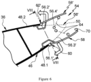
- the overpressure device 54 comprises, for each door 58, at least one retaining means 64, such as a cable for example, connecting the door 58 to a fixed part of the propulsion assembly and limiting the opening of the door 58 beyond the open position.
- the retaining means 64 makes it possible to limit the opening of the door 58 to a predetermined passage section.
- Each retaining means 64 has a first end 64.1 connected to the door 58 and spaced from the articulation 60 as well as a second end 64.2 connected to the nacelle 36, in particular to its primary or secondary structure, and spaced from the articulation 60.
- each locking/unlocking system 62 is configured to automatically switch from the locked state to the unlocked state as soon as the pressure in the interior zone becomes greater than or equal to the given threshold.
- each locking/unlocking system 62 is controllable.
- the overpressure device 54 comprises at least one hydrogen leak detector, for example in the form of a hydrogen detector, configured to detect the presence of hydrogen in the inner zone of the fairing 46 or a pressure sensor 66 positioned in the inner zone and configured to measure a pressure in the inner zone, as well as a control 68 provided by the leak sensor or the pressure sensor 66 and configured to control each locking/unlocking system 62 and command a change of state of each locking/unlocking system 62 from the locked state to the unlocked state as soon as the pressure measured by the pressure sensor 66 is greater than or equal to the given threshold or when a leak is detected.
- the overpressure device 54 comprises a control operable by a person, such as the pilot. for example, positioned in the cockpit, configured to cause a change in state of the overpressure system.
- the pressure relief device 54 may comprise, for each door 58, at least one actuator connected to the door and configured to cause a change in position of the door 58.
- the pressure relief device 54 comprises at least one seal 70 interposed between the fairing 46 and each door 58 when the latter is in the closed position.
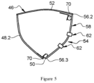
- the opening 56 is positioned at the first side wall 48.1.
- the opening 56 is delimited by a first substantially vertical edge 56.1, positioned in front of the opening 56 and extending to the trailing edge 50, a second substantially horizontal edge 56.2, connecting the first edge 56.1 and the trailing edge 50 as well as a third edge 56.3 which follows the trailing edge 50 and connects the first and second edges 56.1, 56.2.
- the second edge 56.2 follows the junction zone connecting the first side wall 48.1 and the upper wall 52.
- the pressure relief device 54 comprises a single door 58 delimited by first, second and third sides which follow, when the door 58 is in the closed position, respectively the first, second and third edges 56.1, 56.2, 56.3 of the opening 56.
- the articulation 60 is positioned at the first edge 56.1 of the opening 56.
- the overpressure device 54 comprises two locking/unlocking systems 62 distributed over the third edge 56.3 of the opening 56.
- At least one seal 70 is connected to the nacelle 36, in particular to its primary or secondary structure, and extends along the second and third edges 56.2, 56.3.
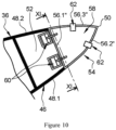
- the pressure relief device 54 comprises first and second doors 58, 58' extending respectively the first and second side walls 48.1, 48.2.
- the first door 58 comprises first, second and third sides which follow, when the first door 58 is in the closed position, respectively the first edge 56.1', the third edge 56.3' and the trailing edge 50 of the opening 56'.
- the second door 58' comprises first, second and third sides which follow, when the second door 58' is in the closed position, respectively the second edge 56.2', the fourth edge 56.4' and the trailing edge 50 of the opening 56'.
- the pressure relief device 54 comprises at least one first articulation 60 connecting the first door 58 to the first edge 56.1' of the opening 56' as well as at least one second articulation 60' connecting the second door 58' to the second edge 56.2' of the opening 56'.
- the pressure relief device 54 comprises locking/unlocking systems 62 distributed on the third sides of the first and second doors 58, 58', located at the trailing edge 50 when they are in the closed position.
- the pressure relief device 54 comprises a first seal 70 positioned at the third side of the first door 58, interposed between the first and second doors 58, 58' when they are in the closed position, a second seal 70' positioned at the of the third edge 56.3' of the opening 56', inserted between the first door 58 and the nacelle 36, as well as a third seal 70" positioned at the level of the fourth edge 56.4' of the opening 56', inserted between the second door 58' and the nacelle 36.
- the overpressure device 54 comprises an opening 56' as well as first and second doors 58, 58' substantially identical to those of the second embodiment.
- the nacelle comprises a median reinforcement 72 having a rear edge 72.1 which follows the trailing edge 50 and against which the first and second doors 58, 58' bear in the closed position.
- the first seal 70 is connected to the median reinforcement 72 and not to the first door 58.
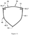
- the opening 56" is positioned at the level of the upper wall 52. It is delimited by a first edge 56.1” positioned in a transverse plane connecting the junction zones which connect the upper wall 52 and the first and second side walls 48.1, 48.2, a second edge 56.2" which follows the junction zone connecting the upper wall 52 and the first side wall 48.1 and which extends from the first edge 56.1" to the trailing edge 50 as well as a third edge 56.3" which follows the junction zone connecting the upper wall 52 and the second side wall 48.2 and extends from the first edge 56.1" to the trailing edge 50.
- the pressure relief device 54 comprises a single door 58 delimited by first, second and third sides which follow, when the door 58 is in the closed position, respectively the first, second and third edges 56.1", 56.2", 56.3" of the opening 56".
- the joint 60 is positioned at the first edge 56.1" of the opening 56".
- the pressure relief device 54 comprises at least first and second locking/unlocking systems 62, 62', at least one first locking/unlocking system 62 being positioned at the second edge 56.2" of the opening 56", at least one second locking/unlocking system 62' being positioned at the third edge 56.3" of the opening 56".
- the overpressure device 54 comprises a first seal 70, connected to the nacelle 36, which extends along the second edge 56.2" of the opening 56 as well as a second seal 70', connected to the nacelle 36, which extends along the third edge 56.3".
- the opening 56 and the door 58 may each have more than three edges or sides and have different geometries.
- the opening 56 must have a sufficient surface area, greater than 500 cm 2 , for example around 4000 cm 2 , to limit the risks of damage to the fairing 46 in the event of excess pressure inside the latter.
Landscapes
- Engineering & Computer Science (AREA)
- Aviation & Aerospace Engineering (AREA)
- Mechanical Engineering (AREA)
- Pressure Vessels And Lids Thereof (AREA)
Claims (10)
- Flugzeugantriebsanordnung, beinhaltend eine Motorisierung (32), ein Treibstoffversorgungssystem (40), das dazu konfiguriert ist, die Motorisierung (32) zu versorgen, sowie eine Verkleidung (46), die einen Innenbereich und einen Außenbereich trennt, wobei die Motorisierung (32) und mindestens ein Teil des Treibstoffversorgungssystems (40) in dem Innenbereich positioniert sind, wobei die Antriebsanordnung eine Überdruckvorrichtung (54) beinhaltet, die dazu konfiguriert ist, entweder, wenn der Innenbereich einen Druck unter einem gegebenen Schwellenwert aufweist, einen nicht aktivierten Zustand, in dem die Überdruckvorrichtung (54) eine im Wesentlichen dichte Barriere zwischen dem Innen- und dem Außenbereich bildet, oder, wenn der Innenbereich einen Druck über oder gleich dem gegebenen Schwellenwert aufweist, einen aktivierten Zustand einzunehmen, und wobei die Überdruckvorrichtung (54) mindestens eine Öffnung (56, 56'), die die Verkleidung (46) durchquert und den Innen- und den Außenbereich in Kommunikation bringt, sowie, für jede Öffnung (56, 56'), mindestens eine Tür (58) beinhaltet, die dazu konfiguriert ist, eine geschlossene Stellung, die dem nicht aktivierten Zustand der Überdruckvorrichtung (54) entspricht und in der die Tür (58) die Öffnung (56, 56') versperrt, und eine geöffnete Stellung, die dem aktivierten Zustand der Überdruckvorrichtung (54) entspricht und in der die Tür (58) die Öffnung (56, 56') mindestens teilweise freigibt, einzunehmen, wobei die Verkleidung (46) eine erste und eine zweite Seitenwand (48.1, 48.2) sowie eine Hinterkante (50) beinhaltet, dadurch gekennzeichnet, dass sich die Seitenwände (48.1, 48.2) im Bereich der Hinterkante (50) treffen und dass die Öffnung (56, 56') der Überdruckvorrichtung (54) im Bereich mindestens einer von der ersten und der zweiten Seitenwand (48.1, 48.2) positioniert ist und sich bis zu der Hinterkante (50) erstreckt.
- Antriebsanordnung nach Anspruch 1, dadurch gekennzeichnet, dass die Überdruckvorrichtung (54) Folgendes beinhaltet:- für jede Tür (58) mindestens ein Gelenk (60), das die Tür (58) und einen festen Teil der Antriebsanordnung verbindet,- mindestens ein Verriegelungs-/Entriegelungssystem (62), das dazu konfiguriert ist, einen verriegelten Zustand, in dem das Verriegelungs-/Entriegelungssystem (62) die Tür (58) in der geschlossenen Stellung hält, und einen entriegelten Zustand, in dem das Verriegelungs-/Entriegelungssystem gestattet, dass die Tür (58) von der geschlossenen Stellung in die geöffnete Stellung übergeht, einzunehmen.
- Antriebsanordnung nach dem vorhergehenden Anspruch, dadurch gekennzeichnet, dass jedes Verriegelungs-/Entriegelungssystem (62) dazu konfiguriert ist, automatisch von dem verriegelten Zustand in den entriegelten Zustand überzugehen, sobald der Druck in dem Innenbereich größer als oder gleich dem gegebenen Schwellenwert wird.
- Antriebsanordnung nach Anspruch 2, dadurch gekennzeichnet, dass die Überdruckvorrichtung (54) eine Steuerung beinhaltet, die dazu konfiguriert ist, eine Zustandsänderung des Verriegelungs-/Entriegelungssystems (62) zu bewirken.
- Antriebsanordnung nach dem vorhergehenden Anspruch, dadurch gekennzeichnet, dass die Überdruckvorrichtung (54) für jede Tür (58) mindestens ein Betätigungselement beinhaltet, das mit der Tür verbunden ist und dazu konfiguriert ist, eine Stellungsänderung der Tür (58) zu bewirken.
- Antriebsanordnung nach einem der Ansprüche 2 bis 5, dadurch gekennzeichnet, dass das Gelenk (60) so konfiguriert ist, dass sich die Tür (58) von der Verkleidung (46) in Richtung des Außenbereichs entfernt, wenn die Tür (58) von der geschlossenen Stellung in die geöffnete Stellung übergeht, wobei das Gelenk (60) eine Schwenkachse (A60) aufweist, die ungefähr in einer Querebene vorne an der Tür (58) positioniert ist.
- Antriebsanordnung nach einem der Ansprüche 2 bis 6, dadurch gekennzeichnet, dass die Überdruckvorrichtung (54) für jede Tür (58) mindestens ein Rückhaltemittel (64) beinhaltet, das die Tür (48) mit einem festen Teil der Antriebsanordnung verbindet.
- Antriebsanordnung nach einem der Ansprüche 2 bis 7, dadurch gekennzeichnet, dass die Überdruckvorrichtung (54) mindestens eine Dichtung (70) beinhaltet, die zwischen die Verkleidung (46) und jede Tür (58) eingefügt ist, wenn sich letztere in der geschlossenen Stellung befindet.
- Antriebsanordnung nach einem der vorhergehenden Ansprüche, dadurch gekennzeichnet, dass die Öffnung (56') der Überdruckvorrichtung im Bereich der ersten und der zweiten Seitenwand (48.1, 48.2) positioniert ist und dass die Überdruckvorrichtung (54) eine erste Tür (58), die die erste Seitenwand (48.1) verlängert, sowie eine zweite Tür (58'), die die zweite Seitenwand (48.2) verlängert, beinhaltet.
- Flugzeug, das mindestens eine Antriebsanordnung nach einem der vorhergehenden Ansprüche beinhaltet.
Applications Claiming Priority (1)
| Application Number | Priority Date | Filing Date | Title |
|---|---|---|---|
| FR2301620 | 2023-02-22 |
Publications (2)
| Publication Number | Publication Date |
|---|---|
| EP4420985A1 EP4420985A1 (de) | 2024-08-28 |
| EP4420985B1 true EP4420985B1 (de) | 2025-04-16 |
Family
ID=86468845
Family Applications (1)
| Application Number | Title | Priority Date | Filing Date |
|---|---|---|---|
| EP24157877.2A Active EP4420985B1 (de) | 2023-02-22 | 2024-02-15 | Flugzeugantriebsanordnung mit mindestens einer überdruckvorrichtung und flugzeug mit mindestens einer solchen antriebseinheit |
Country Status (3)
| Country | Link |
|---|---|
| US (1) | US12583600B2 (de) |
| EP (1) | EP4420985B1 (de) |
| CN (1) | CN118529256A (de) |
Families Citing this family (1)
| Publication number | Priority date | Publication date | Assignee | Title |
|---|---|---|---|---|
| FR3171079A1 (fr) * | 2025-01-06 | 2026-07-10 | Safran Aircraft Engines | Enceinte etanche avec evacuation controlee de surpression |
Family Cites Families (10)
| Publication number | Priority date | Publication date | Assignee | Title |
|---|---|---|---|---|
| US4825644A (en) * | 1987-11-12 | 1989-05-02 | United Technologies Corporation | Ventilation system for a nacelle |
| FR2771776B1 (fr) * | 1997-12-02 | 2000-01-28 | Aerospatiale | Dispositif d'evacuation d'air chaud pour capot d'entree d'air de moteur a reaction, a circuit de degivrage |
| FR2939768B1 (fr) * | 2008-12-12 | 2011-09-09 | Aircelle Sa | Trappe de surpression destinee a etre montee sur une paroi d'une nacelle de turboreacteur |
| FR2960854B1 (fr) | 2010-06-04 | 2012-07-20 | Airbus Operations Sas | Porte a double fonction pour nacelle de moteur d'aeronef |
| FR2978424B1 (fr) * | 2011-07-26 | 2014-05-16 | Lisi Aerospace | Verrou de surpression |
| US10494077B2 (en) * | 2015-11-20 | 2019-12-03 | Airbus Operations Gmbh | Decompression assembly with two decompression openings |
| US11008089B2 (en) | 2018-10-24 | 2021-05-18 | Gulfstream Aerospace Corporation | Fireproof pressure relief assembly |
| EP3683138B1 (de) * | 2019-01-16 | 2021-04-28 | AIRBUS HELICOPTERS DEUTSCHLAND GmbH | Türverriegelungssystem mit einem schnellfreigabemechanismus |
| FR3120603A1 (fr) * | 2021-03-11 | 2022-09-16 | Airbus Operations (S.A.S.) | Mât d’aéronef comprenant une structure primaire tubulaire intégrant au moins une canalisation à double peau et aéronef comportant au moins un tel mât |
| US11597528B2 (en) * | 2021-06-16 | 2023-03-07 | Joby Aero, Inc. | Aircraft energy storage mounting system |
-
2024
- 2024-02-15 EP EP24157877.2A patent/EP4420985B1/de active Active
- 2024-02-20 US US18/581,718 patent/US12583600B2/en active Active
- 2024-02-21 CN CN202410192874.5A patent/CN118529256A/zh active Pending
Also Published As
| Publication number | Publication date |
|---|---|
| US12583600B2 (en) | 2026-03-24 |
| US20240278922A1 (en) | 2024-08-22 |
| EP4420985A1 (de) | 2024-08-28 |
| CN118529256A (zh) | 2024-08-23 |
Similar Documents
| Publication | Publication Date | Title |
|---|---|---|
| EP4129827B1 (de) | Luftfahrzeug mit mindestens einer vorrichtung zur wasserstoffversorgung sowie mindestens einem dichten behälter, in dem mindestens ein ausrüstungsteil der vorrichtung zur wasserstoffversorgung positioniert ist | |
| EP2057071B1 (de) | Verschlusssystem für eine bewegliche gondelverkleidung | |
| EP2139769B1 (de) | Befestigung für pylonkasten an flügeln, festklemmen einer seitenplatte des kastens | |
| EP0391795B1 (de) | Bewegliche Verkleidung für ein Flugzeugtriebwerk | |
| EP3483069B1 (de) | Luftfahrezugtriebwerksbefestigungssystem | |
| EP3505439B1 (de) | Einheit für ein luftfahrzeug, die eine primärstruktur eines aufhängungsmasts umfasst, die an einem flügelkasten durch befestigungselemente befestigt ist und im vorderkantenbereich ein reduziertes volumen aufweist | |
| FR3068008B1 (fr) | Ensemble de motorisation pour un aeronef | |
| EP3505448B1 (de) | Einheit für ein luftfahrzeug, die eine primärstruktur eines aufhängungsmasts umfasst, die an einem flügelkasten mithilfe von anschlüssen reduzierten volumens in der vorderkantenzone befestigt ist | |
| EP2188177A1 (de) | Befestigung einer triebwerksgondelstruktur mittels einer verstärkten messerschneiden-rillen-kupplung | |
| CA2798046A1 (fr) | Structure avant d'avion perfectionnee a compartiment pour train d'atterrissage | |
| EP2447159A2 (de) | Verkleidung eines Luftfahrzeugs, die mit Mitteln zur Begrenzung von Stauphänomenen ausgestattet ist | |
| EP4420985A1 (de) | Flugzeugantriebsanordnung mit mindestens einer überdruckvorrichtung und flugzeug mit mindestens einer solchen antriebseinheit | |
| EP3521173B1 (de) | Einheit für luftfahrzeug, die eine primärstruktur einer aufhängesäule umfasst, die an einem fahrwerkskasten mithilfe einer verschraubten verbindung befestigt ist | |
| EP0846854A1 (de) | Schubumkehrvorrichtung für Strahltriebwerke mittels Klappen, die mit der Gondelfläche fluchten | |
| FR3012793A1 (fr) | Ensemble pour aeronef comprenant une ferrure fixee sur la partie extrados d'un caisson de voilure, pour le montage d'un mat d'accrochage sur ce caisson de voilure | |
| FR2738291A1 (fr) | Inverseur de poussee de turboreacteur a portes associees a un panneau amont formant ecope | |
| EP1535839B1 (de) | Aufhängevorrichtung eines Triebweks unter einem Fluzeugflügel | |
| EP3917831A1 (de) | Tragstruktur mit passiv anpassbarem profil | |
| EP1092859B1 (de) | Schubumkehrvorrichtung für ein Strahltriebwerk | |
| FR3073205A1 (fr) | Attache moteur d'un moteur d'aeronef | |
| EP3527485B1 (de) | Luftfahrzeug umfassend eine frachttüre mit einem verbesserten dichtungssystem | |
| FR2651021A1 (fr) | Inverseur de poussee de turboreacteur, a portes associees a un panneau amont | |
| EP4538513A1 (de) | Antriebseinheit für ein flugzeug | |
| EP2509870A1 (de) | Hintere anordnung einer triebwerksgondel | |
| EP1740456A1 (de) | Flugzeugturbomotor mit verbesserter aerodynamischer installation |
Legal Events
| Date | Code | Title | Description |
|---|---|---|---|
| PUAI | Public reference made under article 153(3) epc to a published international application that has entered the european phase |
Free format text: ORIGINAL CODE: 0009012 |
|
| STAA | Information on the status of an ep patent application or granted ep patent |
Free format text: STATUS: REQUEST FOR EXAMINATION WAS MADE |
|
| 17P | Request for examination filed |
Effective date: 20240215 |
|
| AK | Designated contracting states |
Kind code of ref document: A1 Designated state(s): AL AT BE BG CH CY CZ DE DK EE ES FI FR GB GR HR HU IE IS IT LI LT LU LV MC ME MK MT NL NO PL PT RO RS SE SI SK SM TR |
|
| GRAP | Despatch of communication of intention to grant a patent |
Free format text: ORIGINAL CODE: EPIDOSNIGR1 |
|
| STAA | Information on the status of an ep patent application or granted ep patent |
Free format text: STATUS: GRANT OF PATENT IS INTENDED |
|
| INTG | Intention to grant announced |
Effective date: 20241115 |
|
| GRAS | Grant fee paid |
Free format text: ORIGINAL CODE: EPIDOSNIGR3 |
|
| GRAA | (expected) grant |
Free format text: ORIGINAL CODE: 0009210 |
|
| STAA | Information on the status of an ep patent application or granted ep patent |
Free format text: STATUS: THE PATENT HAS BEEN GRANTED |
|
| AK | Designated contracting states |
Kind code of ref document: B1 Designated state(s): AL AT BE BG CH CY CZ DE DK EE ES FI FR GB GR HR HU IE IS IT LI LT LU LV MC ME MK MT NL NO PL PT RO RS SE SI SK SM TR |
|
| REG | Reference to a national code |
Ref country code: GB Ref legal event code: FG4D Free format text: NOT ENGLISH |
|
| REG | Reference to a national code |
Ref country code: CH Ref legal event code: EP |
|
| REG | Reference to a national code |
Ref country code: IE Ref legal event code: FG4D Free format text: LANGUAGE OF EP DOCUMENT: FRENCH |
|
| REG | Reference to a national code |
Ref country code: DE Ref legal event code: R096 Ref document number: 602024000062 Country of ref document: DE |
|
| REG | Reference to a national code |
Ref country code: NL Ref legal event code: MP Effective date: 20250416 |
|
| PG25 | Lapsed in a contracting state [announced via postgrant information from national office to epo] |
Ref country code: NL Free format text: LAPSE BECAUSE OF FAILURE TO SUBMIT A TRANSLATION OF THE DESCRIPTION OR TO PAY THE FEE WITHIN THE PRESCRIBED TIME-LIMIT Effective date: 20250416 |
|
| REG | Reference to a national code |
Ref country code: AT Ref legal event code: MK05 Ref document number: 1785482 Country of ref document: AT Kind code of ref document: T Effective date: 20250416 |
|
| PG25 | Lapsed in a contracting state [announced via postgrant information from national office to epo] |
Ref country code: FI Free format text: LAPSE BECAUSE OF FAILURE TO SUBMIT A TRANSLATION OF THE DESCRIPTION OR TO PAY THE FEE WITHIN THE PRESCRIBED TIME-LIMIT Effective date: 20250416 Ref country code: ES Free format text: LAPSE BECAUSE OF FAILURE TO SUBMIT A TRANSLATION OF THE DESCRIPTION OR TO PAY THE FEE WITHIN THE PRESCRIBED TIME-LIMIT Effective date: 20250416 Ref country code: PT Free format text: LAPSE BECAUSE OF FAILURE TO SUBMIT A TRANSLATION OF THE DESCRIPTION OR TO PAY THE FEE WITHIN THE PRESCRIBED TIME-LIMIT Effective date: 20250818 |
|
| REG | Reference to a national code |
Ref country code: LT Ref legal event code: MG9D |
|
| PG25 | Lapsed in a contracting state [announced via postgrant information from national office to epo] |
Ref country code: NO Free format text: LAPSE BECAUSE OF FAILURE TO SUBMIT A TRANSLATION OF THE DESCRIPTION OR TO PAY THE FEE WITHIN THE PRESCRIBED TIME-LIMIT Effective date: 20250716 Ref country code: GR Free format text: LAPSE BECAUSE OF FAILURE TO SUBMIT A TRANSLATION OF THE DESCRIPTION OR TO PAY THE FEE WITHIN THE PRESCRIBED TIME-LIMIT Effective date: 20250717 |
|
| PG25 | Lapsed in a contracting state [announced via postgrant information from national office to epo] |
Ref country code: PL Free format text: LAPSE BECAUSE OF FAILURE TO SUBMIT A TRANSLATION OF THE DESCRIPTION OR TO PAY THE FEE WITHIN THE PRESCRIBED TIME-LIMIT Effective date: 20250416 |
|
| PG25 | Lapsed in a contracting state [announced via postgrant information from national office to epo] |
Ref country code: BG Free format text: LAPSE BECAUSE OF FAILURE TO SUBMIT A TRANSLATION OF THE DESCRIPTION OR TO PAY THE FEE WITHIN THE PRESCRIBED TIME-LIMIT Effective date: 20250416 |
|
| PG25 | Lapsed in a contracting state [announced via postgrant information from national office to epo] |
Ref country code: HR Free format text: LAPSE BECAUSE OF FAILURE TO SUBMIT A TRANSLATION OF THE DESCRIPTION OR TO PAY THE FEE WITHIN THE PRESCRIBED TIME-LIMIT Effective date: 20250416 |
|
| PG25 | Lapsed in a contracting state [announced via postgrant information from national office to epo] |
Ref country code: AT Free format text: LAPSE BECAUSE OF FAILURE TO SUBMIT A TRANSLATION OF THE DESCRIPTION OR TO PAY THE FEE WITHIN THE PRESCRIBED TIME-LIMIT Effective date: 20250416 |
|
| PG25 | Lapsed in a contracting state [announced via postgrant information from national office to epo] |
Ref country code: RS Free format text: LAPSE BECAUSE OF FAILURE TO SUBMIT A TRANSLATION OF THE DESCRIPTION OR TO PAY THE FEE WITHIN THE PRESCRIBED TIME-LIMIT Effective date: 20250716 |
|
| PG25 | Lapsed in a contracting state [announced via postgrant information from national office to epo] |
Ref country code: IS Free format text: LAPSE BECAUSE OF FAILURE TO SUBMIT A TRANSLATION OF THE DESCRIPTION OR TO PAY THE FEE WITHIN THE PRESCRIBED TIME-LIMIT Effective date: 20250816 |
|
| PG25 | Lapsed in a contracting state [announced via postgrant information from national office to epo] |
Ref country code: LV Free format text: LAPSE BECAUSE OF FAILURE TO SUBMIT A TRANSLATION OF THE DESCRIPTION OR TO PAY THE FEE WITHIN THE PRESCRIBED TIME-LIMIT Effective date: 20250416 |
|
| PG25 | Lapsed in a contracting state [announced via postgrant information from national office to epo] |
Ref country code: DK Free format text: LAPSE BECAUSE OF FAILURE TO SUBMIT A TRANSLATION OF THE DESCRIPTION OR TO PAY THE FEE WITHIN THE PRESCRIBED TIME-LIMIT Effective date: 20250416 Ref country code: SM Free format text: LAPSE BECAUSE OF FAILURE TO SUBMIT A TRANSLATION OF THE DESCRIPTION OR TO PAY THE FEE WITHIN THE PRESCRIBED TIME-LIMIT Effective date: 20250416 |
|
| REG | Reference to a national code |
Ref country code: DE Ref legal event code: R097 Ref document number: 602024000062 Country of ref document: DE |
|
| PG25 | Lapsed in a contracting state [announced via postgrant information from national office to epo] |
Ref country code: CZ Free format text: LAPSE BECAUSE OF FAILURE TO SUBMIT A TRANSLATION OF THE DESCRIPTION OR TO PAY THE FEE WITHIN THE PRESCRIBED TIME-LIMIT Effective date: 20250416 |
|
| PG25 | Lapsed in a contracting state [announced via postgrant information from national office to epo] |
Ref country code: EE Free format text: LAPSE BECAUSE OF FAILURE TO SUBMIT A TRANSLATION OF THE DESCRIPTION OR TO PAY THE FEE WITHIN THE PRESCRIBED TIME-LIMIT Effective date: 20250416 |
|
| PG25 | Lapsed in a contracting state [announced via postgrant information from national office to epo] |
Ref country code: SK Free format text: LAPSE BECAUSE OF FAILURE TO SUBMIT A TRANSLATION OF THE DESCRIPTION OR TO PAY THE FEE WITHIN THE PRESCRIBED TIME-LIMIT Effective date: 20250416 |
|
| PG25 | Lapsed in a contracting state [announced via postgrant information from national office to epo] |
Ref country code: IT Free format text: LAPSE BECAUSE OF FAILURE TO SUBMIT A TRANSLATION OF THE DESCRIPTION OR TO PAY THE FEE WITHIN THE PRESCRIBED TIME-LIMIT Effective date: 20250416 |
|
| PLBE | No opposition filed within time limit |
Free format text: ORIGINAL CODE: 0009261 |
|
| STAA | Information on the status of an ep patent application or granted ep patent |
Free format text: STATUS: NO OPPOSITION FILED WITHIN TIME LIMIT |
|
| REG | Reference to a national code |
Ref country code: CH Ref legal event code: L10 Free format text: ST27 STATUS EVENT CODE: U-0-0-L10-L00 (AS PROVIDED BY THE NATIONAL OFFICE) Effective date: 20260225 |
|
| 26N | No opposition filed |
Effective date: 20260119 |
|
| PGFP | Annual fee paid to national office [announced via postgrant information from national office to epo] |
Ref country code: DE Payment date: 20260218 Year of fee payment: 3 |
|
| PGFP | Annual fee paid to national office [announced via postgrant information from national office to epo] |
Ref country code: FR Payment date: 20260219 Year of fee payment: 3 |
|
| PG25 | Lapsed in a contracting state [announced via postgrant information from national office to epo] |
Ref country code: LT Free format text: LAPSE BECAUSE OF FAILURE TO SUBMIT A TRANSLATION OF THE DESCRIPTION OR TO PAY THE FEE WITHIN THE PRESCRIBED TIME-LIMIT Effective date: 20250416 |
|
| PG25 | Lapsed in a contracting state [announced via postgrant information from national office to epo] |
Ref country code: SE Free format text: LAPSE BECAUSE OF FAILURE TO SUBMIT A TRANSLATION OF THE DESCRIPTION OR TO PAY THE FEE WITHIN THE PRESCRIBED TIME-LIMIT Effective date: 20250416 |