EP4420857A1 - Kupplungselement für einen extruder - Google Patents
Kupplungselement für einen extruder Download PDFInfo
- Publication number
- EP4420857A1 EP4420857A1 EP23175037.3A EP23175037A EP4420857A1 EP 4420857 A1 EP4420857 A1 EP 4420857A1 EP 23175037 A EP23175037 A EP 23175037A EP 4420857 A1 EP4420857 A1 EP 4420857A1
- Authority
- EP
- European Patent Office
- Prior art keywords
- receiving
- coupling element
- extruder
- drive unit
- weld seam
- Prior art date
- Legal status (The legal status is an assumption and is not a legal conclusion. Google has not performed a legal analysis and makes no representation as to the accuracy of the status listed.)
- Granted
Links
Images


Classifications
-
- B—PERFORMING OPERATIONS; TRANSPORTING
- B29—WORKING OF PLASTICS; WORKING OF SUBSTANCES IN A PLASTIC STATE IN GENERAL
- B29C—SHAPING OR JOINING OF PLASTICS; SHAPING OF MATERIAL IN A PLASTIC STATE, NOT OTHERWISE PROVIDED FOR; AFTER-TREATMENT OF THE SHAPED PRODUCTS, e.g. REPAIRING
- B29C48/00—Extrusion moulding, i.e. expressing the moulding material through a die or nozzle which imparts the desired form; Apparatus therefor
- B29C48/25—Component parts, details or accessories; Auxiliary operations
- B29C48/252—Drive or actuation means; Transmission means; Screw supporting means
-
- F—MECHANICAL ENGINEERING; LIGHTING; HEATING; WEAPONS; BLASTING
- F16—ENGINEERING ELEMENTS AND UNITS; GENERAL MEASURES FOR PRODUCING AND MAINTAINING EFFECTIVE FUNCTIONING OF MACHINES OR INSTALLATIONS; THERMAL INSULATION IN GENERAL
- F16D—COUPLINGS FOR TRANSMITTING ROTATION; CLUTCHES; BRAKES
- F16D1/00—Couplings for rigidly connecting two coaxial shafts or other movable machine elements
- F16D1/10—Quick-acting couplings in which the parts are connected by simply bringing them together axially
- F16D1/101—Quick-acting couplings in which the parts are connected by simply bringing them together axially without axial retaining means rotating with the coupling
-
- F—MECHANICAL ENGINEERING; LIGHTING; HEATING; WEAPONS; BLASTING
- F16—ENGINEERING ELEMENTS AND UNITS; GENERAL MEASURES FOR PRODUCING AND MAINTAINING EFFECTIVE FUNCTIONING OF MACHINES OR INSTALLATIONS; THERMAL INSULATION IN GENERAL
- F16D—COUPLINGS FOR TRANSMITTING ROTATION; CLUTCHES; BRAKES
- F16D9/00—Couplings with safety member for disconnecting, e.g. breaking or melting member
- F16D9/06—Couplings with safety member for disconnecting, e.g. breaking or melting member by breaking due to shear stress
-
- F—MECHANICAL ENGINEERING; LIGHTING; HEATING; WEAPONS; BLASTING
- F16—ENGINEERING ELEMENTS AND UNITS; GENERAL MEASURES FOR PRODUCING AND MAINTAINING EFFECTIVE FUNCTIONING OF MACHINES OR INSTALLATIONS; THERMAL INSULATION IN GENERAL
- F16D—COUPLINGS FOR TRANSMITTING ROTATION; CLUTCHES; BRAKES
- F16D9/00—Couplings with safety member for disconnecting, e.g. breaking or melting member
- F16D9/06—Couplings with safety member for disconnecting, e.g. breaking or melting member by breaking due to shear stress
- F16D9/08—Couplings with safety member for disconnecting, e.g. breaking or melting member by breaking due to shear stress over a single area encircling the axis of rotation, e.g. shear necks on shafts
-
- B—PERFORMING OPERATIONS; TRANSPORTING
- B29—WORKING OF PLASTICS; WORKING OF SUBSTANCES IN A PLASTIC STATE IN GENERAL
- B29C—SHAPING OR JOINING OF PLASTICS; SHAPING OF MATERIAL IN A PLASTIC STATE, NOT OTHERWISE PROVIDED FOR; AFTER-TREATMENT OF THE SHAPED PRODUCTS, e.g. REPAIRING
- B29C48/00—Extrusion moulding, i.e. expressing the moulding material through a die or nozzle which imparts the desired form; Apparatus therefor
- B29C48/25—Component parts, details or accessories; Auxiliary operations
- B29C48/36—Means for plasticising or homogenising the moulding material or forcing it through the nozzle or die
- B29C48/395—Means for plasticising or homogenising the moulding material or forcing it through the nozzle or die using screws surrounded by a cooperating barrel, e.g. single screw extruders
- B29C48/40—Means for plasticising or homogenising the moulding material or forcing it through the nozzle or die using screws surrounded by a cooperating barrel, e.g. single screw extruders using two or more parallel screws or at least two parallel non-intermeshing screws, e.g. twin screw extruders
-
- F—MECHANICAL ENGINEERING; LIGHTING; HEATING; WEAPONS; BLASTING
- F16—ENGINEERING ELEMENTS AND UNITS; GENERAL MEASURES FOR PRODUCING AND MAINTAINING EFFECTIVE FUNCTIONING OF MACHINES OR INSTALLATIONS; THERMAL INSULATION IN GENERAL
- F16D—COUPLINGS FOR TRANSMITTING ROTATION; CLUTCHES; BRAKES
- F16D1/00—Couplings for rigidly connecting two coaxial shafts or other movable machine elements
- F16D1/10—Quick-acting couplings in which the parts are connected by simply bringing them together axially
- F16D2001/103—Quick-acting couplings in which the parts are connected by simply bringing them together axially the torque is transmitted via splined connections
Definitions
- the invention relates to a coupling element for connecting an extruder screw to a drive unit of a twin-screw extruder, with two receiving bushings connected to one another in a connecting region, wherein the first receiving bushing is provided for receiving a shaft end of the drive unit and the second receiving bushing is provided for receiving one of the extruder screws.
- Extruder systems are used to mix, convey and compress different materials.
- the materials are usually heated in the process.
- This process is carried out using one or two rotating extruder screws arranged parallel to one another. Consequently, a distinction is made between single-screw and twin-screw extruders.
- twin-screw extruders the principle of power splitting is used in the gearbox and the motor torque generated is divided between two output shafts. Ideally, the size of the output torques of both shafts is identical.
- the output shafts of the gearbox then drive the two extruder screws.
- the EP2939943A1 shows an electronic control system for protecting a system from overload.
- the torque is measured on the gearbox output shafts. If a torque limit, a torque gradient limit or an impermissibly high vibration is detected, a switchable clutch between the motor and gearbox opens and the speed of the motor is reduced via a frequency converter.
- a safety coupling is described that has two coupling halves with shear pins arranged between them. In the event of an overload, the shear pins form a predetermined breaking point, shear off and thereby interrupt the transmitted torque. The shear pins can be replaced and the safety coupling is functional again.
- the safety coupling requires a certain radial installation space, which is usually not available in twin-screw extruders in particular due to the defined distance between the axles.
- One embodiment relates to a coupling element for connecting an extruder screw to a drive unit of a twin-screw extruder, with two receiving bushings connected to one another in a connecting region, the first receiving bushing being provided for receiving a shaft end of the drive unit and the second receiving bushing for receiving one of the extruder screws.
- the connecting region has a plurality of circumferentially distributed and radially extending bores or a circumferentially extending weld seam, the connecting region via the bores or the weld seam having a reduced breaking moment in the event of a torsional load compared to an adjacent structural region of the receiving bushings.
- the receiving bushings are arranged coaxially to one another and are preferably cylindrical and have a profile on an inner surface for torque transmission between the receiving bushing and the drive unit on the one hand and the extruder screw on the other.
- the drive unit can comprise a drive motor and a gear stage or a gearbox.
- the power is usually split via a gearbox.
- a belt drive can also be connected between the motor and gearbox in front of the gearbox in order to achieve a higher gear ratio.
- the torque provided can be distributed or split between both extruder screws via the drive unit. It is preferred if the torque is distributed equally between the extruder screws.
- Each shaft end of the drive unit is assigned to a respective output shaft of the drive unit.
- connection area forms the transition between the two receiving bushes.
- the two receiving bushes are designed as one component, i.e. in one piece, as a result of the connection area. This does not affect the fact that the two receiving bushes can be present as two separate and mutually separate workpieces at one point during the manufacturing process.
- the connection area can generally comprise the same material as the adjacent structural area of the receiving bushes, as for example in the embodiment with the plurality of circumferentially distributed and radially extending bores. In the embodiment with the circumferentially extending weld seam, the connection area can also comprise the material of the weld seam.
- the torsional load occurs during normal operation of the twin-screw extruder as a result of the drive torque applied by the drive unit on the one hand and the resistance of the extruder screws due to the extruded material to be processed on the other hand.
- the design of the coupling element with either the circumferentially distributed and radially running holes or the circumferentially running weld seam form a predetermined breaking point that fails in the event of an overload and thus protects the other system components.
- no additional shear element e.g. shear pins, is used; instead, the coupling element itself has a weakened area. This area is designed in such a way that it can be changed with the smallest possible adjustments so that a defined breaking moment can be achieved with the help of calculations.
- the design of the coupling element with either the circumferentially distributed and radially running holes or the circumferentially running weld seam enables an even more compact design than conventional designs allow.
- no additional axial installation space is required compared to conventional designs.
- Existing systems can also be retrofitted with the coupling element. because the required installation space and connection dimensions can be selected identically.
- connection area forms a reduced cross-section compared to the adjacent structural area due to the holes or the weld seam. This inserts a predetermined breaking point into the connection area.
- connection area is designed over the hole diameter and the circumferential distance between the holes and/or the inner diameter and the outer diameter, in particular of the weld seam, with regard to the breaking moment to be achieved.
- the circumferential distance between the bores is at most 1.5 times, in particular at most 1.2 times, the bore diameter. This ensures that a defined crack path is created in the fracture plane, since the torsional shear stresses act at an angle of 45°.
- the object is also achieved by a twin-screw extruder with a drive unit and two extruder screws driven by the drive unit in a power-split manner, characterized in that the drive unit is connected to the extruder screws via a coupling element according to one of the preceding claims.
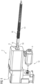
- the Figure 1 shows a perspective and partially exploded view of a twin-screw extruder 2.
- the twin-screw extruder 2 structurally comprises a drive unit 12, which in this case is made up of a motor unit 4 and a gear unit 6.
- the gear unit 6 can transmit the drive torque of the motor unit 4 in a power-split manner to two output shafts 8 arranged parallel to one another.
- a first and a second extrusion screw 14, 16 are connected to the two output shafts 8 via a coupling element 10.
- the two extrusion screws 14, 16 have a small axial distance from one another, corresponding to the output shafts 8.
- Other components of the system can be cylinders, filling hoppers, heating bands, nozzles and a machine frame, although this is not shown.
- the Figures 2 and 3 show, in a perspective and a sectional view a) and b), two embodiments of a coupling element 10 according to the invention.
- the coupling element 10 comprises in each embodiment two receiving bushings 18, 20 which are connected to one another in a connecting region 22.
- the two receiving bushings 18, 20 are preferably identical and are placed concentrically next to one another and connected to one another via the connecting region 22.
- the first receiving bushing 18 is intended to receive a shaft end of the drive unit 12 and the second receiving bushing 20 is intended to receive one of the extruder screws 14, 16.
- each of the receiving bushings 18, 20 forms a longitudinal toothing which can form a positive connection for torque transmission with a corresponding longitudinal toothing 30 of the drive shafts of the drive unit 12 and the extruder screw 14, 16.
- the connection area 22 has a plurality of circumferentially distributed and radially extending bores 24 - see Figures 2a) and 2b ) -or a comprehensive running weld seam 26 - see Figures 3a) and 3b ). In any case, the connection area has a reduced breaking moment under torsional loading compared to an adjacent structural area 28 of the receiving bushes 18, 20.
- connection area 22 forms a reduced cross-section compared to the adjacent structural area 28 due to the holes 24 or the weld seam 26.
- the connection area 22 is designed over the hole diameter and the circumferential distance of the holes 24 from each other and the inner diameter and the outer diameter of the weld seam 26 with regard to the breaking moment to be achieved. It is preferred, as shown here, that a radial dimension of the connection area does not exceed a radial dimension of the receiving bushes connected to each other.
- the circumferential distance between the holes 24 is preferably at most 1.5 times, in particular at most 1.2 times, the hole diameter.
Landscapes
- Engineering & Computer Science (AREA)
- General Engineering & Computer Science (AREA)
- Mechanical Engineering (AREA)
- Extrusion Moulding Of Plastics Or The Like (AREA)
- Processing And Handling Of Plastics And Other Materials For Molding In General (AREA)
Abstract
Description
- Die Erfindung betrifft ein Kupplungselement zur Verbindung jeweils einer Extruderschnecke mit einer Antriebseinheit eines Doppelschneckenextruders, mit zwei in einen Verbindungsbereich miteinander verbundenen Aufnahmebuchsen, wobei die erste Aufnahmebuchse zur Aufnahme eines Wellenendes der Antriebseinheit und die zweite Aufnahmebuchse zur Aufnahme eines der Extruderschnecken vorgesehen ist.
- Extruderanlagen dienen zur Durchmischung, Förderung und Verdichtung verschiedener Materialien. In der Regel werden die Materialien dabei erhitzt. Dieser Vorgang wird über eine oder zwei rotierende und parallel zueinander angeordnete Extruderschnecken realisiert. Folglich unterscheidet man zwischen Einschnecken- und Doppelschneckenextrudern. Bei Doppelschneckenextrudern wird im Getriebe das Prinzip der Leistungsverzweigung genutzt und das erzeugte Motordrehmoment auf zwei Abtriebswellen aufgeteilt. Im Idealfall ist dabei die Größe der Abtriebsdrehmomente beider Wellen identisch. Die Abtriebswellen des Getriebes treiben dann die zwei Extruderschnecken an. Es gibt Extruderanlagen mit gleichsinnig drehenden und mit gegensinnig drehenden Schnecken. Zudem sind i.d.R. die Verdrehwinkel der beiden Schnecken zueinander synchronisiert.
- Störungen des Regelbetriebs, hervorgerufen beispielsweise durch Verunreinigungen oder sonstige Inhomogenitäten im Ausgangsmaterial oder erkaltete Materialrückstände eines früheren Extrusionsvorgangs, können zu einer ungleichförmigen Lastverteilung des Drehmoments auf die Abtriebswellen führen. System- bzw. prozessbedingt haben die Extruderschnecken einen definierten Achsabstand zueinander, der den Außendurchmesser der Getriebeabtriebswellen limitiert. Dementsprechend hoch ist die Drehmomentdichte in diesen Teilen bereits bei Nennlast. Kommen nun Lastspitzen durch zuvor erwähnte Effekte hinzu, kann die Überlastung einzelner Komponenten die Folge sein. Es besteht folglich ein ständiges Bedürfnis die Komponenten einer Extruderanlage während des Regelbetriebes vor einer Überlastung zu schützen.
- Die
EP 2939943 A1 zeigt eine elektronische Regelung zum Schutz einer Anlage vor einer Überlastung. Das Drehmoment wird messtechnisch an den Getriebeabtriebswellen erfasst. Wird ein Drehmomentgrenzwert, ein Gradientengrenzwert des Drehmoments oder eine unzulässig hohe Schwingung detektiert, so öffnet eine schaltbare Kupplung zwischen Motor und Getriebe und die Drehzahl des Motors wird über einen Frequenzumrichter runtergeregelt. In derEP 3 378 624 A1 ist eine Sicherheitskupplung beschrieben, die zwei Kupplungshälften aufweist, zwischen denen Scherstifte angeordnet. Bei einer Überlastung bilden die Scherstifte eine Sollbruchstelle, scheren ab und unterbrechen hierüber das übertragene Drehmoment. Die Scherstifte können ersetzt werden und die Sicherheitskupplung ist erneut funktionstüchtig. Die Sicherheitskupplung erfordert allerdings einen bestimmten radialen Bauraum, der insbesondere bei Doppelschneckenextrudern infolge des definierten Achsabstandes zueinander regelmäßig nicht gegeben ist. - Es ist die Aufgabe der Erfindung Maßnahmen aufzuzeigen, mit denen ein Kupplungselement für einen Doppelschneckenextruders unter Berücksichtigung des eingeschränkten Achsabstandes bereitgestellt werden kann.
- Die Lösung der Aufgabe erfolgt durch ein Kupplungselement mit den Merkmalen des Anspruchs 1. Bevorzugte Ausgestaltungen sind in den Unteransprüchen und der nachfolgenden Beschreibung angegeben, die jeweils einzeln oder in Kombination einen Aspekt der Erfindung darstellen können. Wenn ein Merkmal in Kombination mit einem anderen Merkmal dargestellt wird, dient dies nur der vereinfachten Darstellung der Erfindung und soll keinesfalls bedeuten, dass dieses Merkmal nicht auch ohne das andere Merkmal eine Weiterbildung der Erfindung sein kann.
- Eine Ausführungsform betrifft ein Kupplungselement zur Verbindung jeweils einer Extruderschnecke mit einer Antriebseinheit eines Doppelschneckenextruders, mit zwei in einen Verbindungsbereich miteinander verbundenen Aufnahmebuchsen, wobei die erste Aufnahmebuchse zur Aufnahme eines Wellenendes der Antriebseinheit und die zweite Aufnahmebuchse zur Aufnahme eines der Extruderschnecken vorgesehen ist. Der Verbindungsbereich weist eine Mehrzahl umfänglich verteilte und radial verlaufende Bohrungen oder eine umfänglich verlaufende Schweißnaht auf, wobei der Verbindungsbereich über die Bohrungen oder die Schweißnaht über ein reduziertes Bruchmoment bei einer Torsionsbelastung gegenüber einem angrenzenden Strukturbereich der Aufnahmebuchsen verfügt.
- Die Aufnahmebuchsen sind koaxial zueinander angeordnet und bevorzugt zylindrisch ausgeführt und weisen auf einer Innenfläche eine Profilierung zur Drehmomentübertragung zwischen der Aufnahmebuchse und der Antriebseinheit einerseits und der Extruderschnecke andererseits auf.
- Die Antriebseinheit kann einen Antriebsmotor und eine Übersetzungsstufe bzw. ein Getriebe umfassen. Üblicherweise erfolgt die Leistungsverzweigung über ein Getriebe. Vor dem Getriebe kann auch ein Riementrieb zwischen Motor und Getriebe geschaltet sein, um eine größere Übersetzung zu realisieren. Über die Antriebseinheit kann das bereitgestellte Drehmoment auf beide Extruderschnecken verteilt bzw. verzweigt werden. Bevorzugt ist, wenn das Drehmoment zu gleichen Anteilen auf die Extruderschnecken verteilt wird. Jedes Wellenende der Antriebseinheit ist eine jeweiligen Ausgangwelle der Antriebseinheit zugeordnet.
- Der Verbindungsbereich bildet den Übergang zwischen den beiden Aufnahmebuchsen. Die beiden Aufnahmebuchsen sind infolge des Verbindungbereichs als ein Bauteil, d.h. einstückig, ausgeführt. Hiervon unberührt ist, dass die beiden Aufnahmebuchse zu einem Zeitpunkt während des Fertigungsprozesses als zwei separate und voneinander getrennte Werkstücke vorliegenden können. Der Verbindungsbereich kann im Allgemeinen das gleiche Material wie der benachbarte Strukturbereich der Aufnahmebuchsen umfassen, wie beispielsweise bei der Ausführungsform mit der Mehrzahl umfänglich verteilter und radial verlaufender Bohrungen. Bei der Ausführungsform mit der umfänglich verlaufenden Schweißnaht kann der Verbindungsbereich außerdem das Material der Schweißnaht umfassen.
- Die Torsionsbelastung ergibt sich während eines Regelbetriebs des Doppelschneckenextruders infolge des von der Antriebseinheit aufgebrachten Antriebsmoments einerseits und des von den Extruderschnecken entgegengesetzten Widerstandes infolge des zu bearbeitenden Extrudiergutes andererseits.
- Die Ausführungsformen des Kupplungselements entweder mit den umfänglich verteilten und radial verlaufenden Bohrungen oder der umfänglich verlaufenden Schweißnaht bilden eine Sollbruchstelle aus, die bei Überlast versagt und so die übrigen Anlagenkomponenten schützt. Es ist jedoch kein zusätzliches Scherelement, z.B. Scherstifte, eingesetzt, sondern das Kupplungselement selbst weist einen geschwächten Bereich auf. Dieser Bereich ist so ausgeführt, dass er mit möglichst kleinen Anpassungen so verändert werden kann, dass mit Hilfe von Berechnungen ein definiertes Bruchmoment erreicht werden kann.
- Die Ausführungsformen des Kupplungselements entweder mit den umfänglich verteilten und radial verlaufenden Bohrungen oder der umfänglich verlaufenden Schweißnaht ermöglichen eine noch kompaktere Bauweise, als es die herkömmlichen Konstruktionen erlauben. Insbesondere ist verglichen mit den herkömmlichen Konstruktionen kein zusätzlicher axialer Bauraum erforderlich. Mit dem Kupplungselement können auch bestehende Anlagen nachgerüstet werden, da der benötigte Einbauraum und die Anschlussmaße identisch gewählt werden können.
- In einer bevorzugten Ausgestaltung bildet der Verbindungsbereich infolge der Bohrungen oder der Schweißnaht einen reduzierten Querschnitt gegenüber dem angrenzenden Strukturbereich aus. Es wird hiermit eine Sollbruchstelle in den Verbindungsbereich eingefügt. Insbesondere kann vorgesehen sein, dass der Verbindungsbereich über den Bohrungsdurchmesser und den umfänglichen Abstand der Bohrungen zueinander und/oder den Innendurchmesser und den Außendurchmesser, insbesondere der Schweißnaht, bezüglich des zu erzielenden Bruchmoments ausgelegt ist.
- Bei der Ausführungsform mit den umfänglich verteilten und radial verlaufenden Bohrungen ist bevorzugt vorgesehen, dass der umfängliche Abstand zwischen den Bohrungen höchstens das 1,5-fache, insbesondere höchstens das 1,2-fache, des Bohrungsdurchmessers beträgt. Hierdurch ist gewährleitet, dass ein definierter Rissverlauf in der Bruchebene entsteht, da die Torsionsschubspannungen unter einem Winkel von 45° wirken.
- Die Aufgabe wird zudem gelöst durch einen Doppelschneckenextruder mit einer Antriebseinheit und zwei von der Antriebseinheit leistungsverzweigt angetriebene Extruderschnecken, dadurch gekennzeichnet, dass die Antriebseinheit mit den Extruderschnecken über jeweils ein Kupplungselement nach einem der vorangegangenen Ansprüche verbunden ist.
- Nachfolgend wird die Erfindung unter Bezugnahme auf die anliegenden Zeichnungen anhand bevorzugter Ausführungsbeispiele exemplarisch erläutert, wobei die nachfolgend dargestellten Merkmale sowohl jeweils einzeln als auch in Kombination einen Aspekt der Erfindung darstellen können. Es zeigen:
-
Figur 1 : eine perspektivische und teilweise explodierte Darstellung eines Doppelschneckenextruders; -
Figuren 2a ), 2b): eine perspektivische und eine geschnittene Darstellung eines Kupplungselements in einer ersten Ausführung und -
Figuren 3a ), 3b): eine perspektivische und eine geschnittene Darstellung eines Kupplungselements in einer zweiten Ausführung. - Die
Figur 1 zeigt in perspektivischer und teilweise explodierter Darstellung einen Doppelschneckenextruder 2. Der Doppelschneckenextruder 2 umfasst strukturell eine Antriebseinheit 12, die sich vorliegend aus einer Motoreinheit 4 und einer Getriebeeinheit 6 zusammensetzt. Die Getriebeeinheit 6 kann das Antriebsmoment der Motoreinheit 4 leistungsverzweigt an zwei parallel zueinander angeordnete Ausgangswellen 8 übertragen werden kann. Mit den beiden Ausgangswellen 8 sind jeweils über ein Kupplungselement 10 eine erste und eine zweite Extrusionsschnecke 14, 16 verbunden. Die beiden Extrusionsschnecken 14, 16 weisen, entsprechend den Ausgangswellen 8, einen geringen Achsabstand zueinander auf. Weitere Bestandteile der Anlage können Zylinder, Befülltrichter, Heizbänder, Düsen und ein Maschinengestell sein, was allerdings nicht abgebildet ist. - Die
Figuren 2 und3 zeigen, jeweils in einer perspektivischen und einer geschnittenen Darstellung a) und b), zwei Ausführungsformen eines erfindungsgemäßen Kupplungselements 10. Das Kupplungselement 10 umfasst in jeder Ausführungsform zwei Aufnahmebuchsen 18, 20, die in einem Verbindungsbereich 22 miteinander verbunden sind. Die beiden Aufnahmebuchsen 18, 20 sind bevorzugt identisch ausgeführt und über den Verbindungsbereich 22 konzentrisch aneinander gesetzt und miteinander verbunden. Die erste Aufnahmebuchse 18 ist zur Aufnahme eines Wellenendes der Antriebseinheit 12 und die zweite Aufnahmebuchse 20 zur Aufnahme eines der Extruderschnecken 14, 16 vorgesehen. Ein Innenumfang jeder der Aufnahmebuchse 18, 20 bildet vorliegend eine Längsverzahnung aus, die mit einer korrespondierenden Längsverzahnung 30 der Antriebswellen der Antriebseinheit 12 und der Extruderschnecke 14, 16 eine formschlüssige Verbindung zur Drehmomentübertragung eingehen kann. Der Verbindungsbereich 22 verfügt über eine Mehrzahl umfänglich verteilter und radial verlaufender Bohrungen 24 - sieheFiguren 2a) und 2b ) -oder über eine umfänglich verlaufende Schweißnaht 26 - sieheFiguren 3a) und 3b ). Der Verbindungsbereich verfügt in jedem Fall bei einer Torsionsbelastung über ein reduziertes Bruchmoment gegenüber einem angrenzenden Strukturbereich 28 der Aufnahmebuchsen 18, 20. - In den Querschnittsdarstellungen der
Figuren 2b ) und3b ) ist zu erkennen, dass der Verbindungsbereich 22 infolge der Bohrungen 24 oder der Schweißnaht 26 einen reduzierten Querschnitt gegenüber dem angrenzenden Strukturbereich 28 ausbildet. Der Verbindungsbereich 22 ist über den Bohrungsdurchmesser und den umfänglichen Abstand der Bohrungen 24 zueinander und den Innendurchmesser und den Außendurchmesser der Schweißnaht 26 bezüglich des zu erzielenden Bruchmoments ausgelegt. Bevorzugt ist, wie vorliegend dargestellt, dass ein radiales Maß des Verbindungsbereichs ein radiales Maß der miteinander verbundenen Aufnahmebuchsen nicht übersteigt. Der umfängliche Abstand zwischen den Bohrungen 24 beträgt bevorzugt höchstens das 1,5-fache, insbesondere höchstens das 1,2-fache, des Bohrungsdurchmessers. -
- 2
- Doppelschneckenextruder
- 4
- Motoreinheit
- 6
- Getriebeeinheit
- 8
- Ausgangswelle
- 10
- Kupplungselement
- 12
- Antriebseinheit
- 14
- Extruderschnecke
- 16
- Extruderschnecke
- 18
- Aufnahmebuchse
- 20
- Aufnahmebuchse
- 22
- Verbindungsbereich
- 24
- Bohrung
- 26
- Schweißnaht
- 28
- Strukturbereich
- 30
- Längsverzahnung
Claims (7)
- Kupplungselement (10) zur Verbindung jeweils einer Extruderschnecke (14, 16) mit einer Antriebseinheit (12) eines Doppelschneckenextruders (2), umfassend zwei in einen Verbindungsbereich (22) miteinander verbundene Aufnahmebuchsen (18, 20), wobei die erste Aufnahmebuchse (18) zur Aufnahme eines Wellenendes der Antriebseinheit (12) und die zweite Aufnahmebuchse (20) zur Aufnahme einer der Extruderschnecken (14, 16) vorgesehen ist,
dadurch gekennzeichnet,
dass der Verbindungsbereich (22) eine Mehrzahl umfänglich verteilte und radial verlaufende Bohrungen (24) oder eine umfänglich verlaufende Schweißnaht (26) aufweist, wobei der Verbindungsbereich (22) über die Bohrungen (24) oder die Schweißnaht (26) über ein reduziertes Bruchmoment bei einer Torsionsbelastung gegenüber einem angrenzenden Strukturbereich (28) der Aufnahmebuchsen (18, 20) verfügt. - Kupplungselement (10) nach Anspruch 1, dadurch gekennzeichnet, dass der Verbindungsbereich (22) infolge der Bohrungen (24) oder der Schweißnaht (26) einen reduzierten Querschnitt gegenüber dem angrenzenden Strukturbereich (28) ausbildet.
- Kupplungselement (10) nach Anspruch 1 oder 2, dadurch gekennzeichnet, dass der Verbindungsbereich (22) über den Bohrungsdurchmesser und den umfänglichen Abstand der Bohrungen (24) zueinander und/oder den Innendurchmesser und den Außendurchmesser, insbesondere des Schweißnahts, bezüglich des zu erzielenden Bruchmoments ausgelegt ist.
- Kupplungselement (10) nach einem der Ansprüche 1 bis 3, dadurch gekennzeichnet, dass das Bruchmoment in einem Bereich zwischen 11.000 Nm und 14.000 Nm liegt.
- Kupplungselement (10) nach einem der Ansprüche 1 bis 4, dadurch gekennzeichnet, dass der umfängliche Abstand zwischen den Bohrungen (24) höchstens das 1,5-fache, insbesondere höchstens das 1,2-fache, des Bohrungsdurchmessers beträgt.
- Kupplungselement (10) nach einem der Ansprüche 1 bis 5, dadurch gekennzeichnet, dass ein radiales Maß des Verbindungsbereichs (22) ein radiales Maß der miteinander verbundenen Aufnahmebuchsen (18, 20) nicht übersteigt.
- Doppelschneckenextruder (2) mit einer Antriebseinheit (12) und zwei von der Antriebseinheit (12) leistungsverzweigt angetriebene Extruderschnecken (14, 16), dadurch gekennzeichnet, dass die Antriebseinheit mit den Extruderschnecken (14, 16) über jeweils ein Kupplungselement (10) nach einem der vorangegangenen Ansprüche verbunden ist.
Priority Applications (4)
| Application Number | Priority Date | Filing Date | Title |
|---|---|---|---|
| EP23175037.3A EP4420857B1 (de) | 2023-05-24 | 2023-05-24 | Kupplungselement für einen extruder |
| EP24725909.6A EP4719739A1 (de) | 2023-05-24 | 2024-05-21 | Kupplungselement für einen extruder |
| CN202480034583.1A CN121263291A (zh) | 2023-05-24 | 2024-05-21 | 用于挤出机的联接元件 |
| PCT/EP2024/063944 WO2024240759A1 (de) | 2023-05-24 | 2024-05-21 | Kupplungselement für einen extruder |
Applications Claiming Priority (1)
| Application Number | Priority Date | Filing Date | Title |
|---|---|---|---|
| EP23175037.3A EP4420857B1 (de) | 2023-05-24 | 2023-05-24 | Kupplungselement für einen extruder |
Publications (2)
| Publication Number | Publication Date |
|---|---|
| EP4420857A1 true EP4420857A1 (de) | 2024-08-28 |
| EP4420857B1 EP4420857B1 (de) | 2025-04-23 |
Family
ID=86603787
Family Applications (2)
| Application Number | Title | Priority Date | Filing Date |
|---|---|---|---|
| EP23175037.3A Active EP4420857B1 (de) | 2023-05-24 | 2023-05-24 | Kupplungselement für einen extruder |
| EP24725909.6A Pending EP4719739A1 (de) | 2023-05-24 | 2024-05-21 | Kupplungselement für einen extruder |
Family Applications After (1)
| Application Number | Title | Priority Date | Filing Date |
|---|---|---|---|
| EP24725909.6A Pending EP4719739A1 (de) | 2023-05-24 | 2024-05-21 | Kupplungselement für einen extruder |
Country Status (3)
| Country | Link |
|---|---|
| EP (2) | EP4420857B1 (de) |
| CN (1) | CN121263291A (de) |
| WO (1) | WO2024240759A1 (de) |
Citations (6)
| Publication number | Priority date | Publication date | Assignee | Title |
|---|---|---|---|---|
| EP2179834A2 (de) * | 2008-10-21 | 2010-04-28 | Kabushiki Kaisha Kobe Seiko Sho (Kobe Steel, Ltd.) | Leistungsübertragungsstruktur und Mischgerät bzw. Extruder mit zwei Schäften |
| WO2010109486A1 (en) * | 2009-03-23 | 2010-09-30 | Steer Engineering Private Limited | A safety device in torque transmission system |
| EP2939943A1 (de) | 2014-05-02 | 2015-11-04 | Rondo AG | Zuschnitt zur Bildung einer quaderförmigen Verpackung sowie Verpackung mit einem Kragenabschnitt und einer inneren Unterteilung |
| EP3378624A1 (de) | 2017-03-24 | 2018-09-26 | Veka AG | Sicherheitskupplung für einen doppelschneckenextruder |
| DE202019106047U1 (de) * | 2019-10-30 | 2019-11-11 | Veka Ag | Doppelschneckenextruder mit Sicherheitskupplung |
| WO2020169927A1 (fr) * | 2019-02-21 | 2020-08-27 | Safran Aircraft Engines | Arbre de transmission comprenant une section fusible et procédé de protection contre un sur-couple d'un tel arbre de transmission |
Family Cites Families (2)
| Publication number | Priority date | Publication date | Assignee | Title |
|---|---|---|---|---|
| US8047919B2 (en) * | 2008-04-04 | 2011-11-01 | Gkn Driveline North America, Inc. | Sideshaft with interconnecting fuse |
| JP2012167793A (ja) * | 2011-02-16 | 2012-09-06 | Toyota Motor Corp | 車両用ドライブシャフト |
-
2023
- 2023-05-24 EP EP23175037.3A patent/EP4420857B1/de active Active
-
2024
- 2024-05-21 EP EP24725909.6A patent/EP4719739A1/de active Pending
- 2024-05-21 WO PCT/EP2024/063944 patent/WO2024240759A1/de not_active Ceased
- 2024-05-21 CN CN202480034583.1A patent/CN121263291A/zh active Pending
Patent Citations (6)
| Publication number | Priority date | Publication date | Assignee | Title |
|---|---|---|---|---|
| EP2179834A2 (de) * | 2008-10-21 | 2010-04-28 | Kabushiki Kaisha Kobe Seiko Sho (Kobe Steel, Ltd.) | Leistungsübertragungsstruktur und Mischgerät bzw. Extruder mit zwei Schäften |
| WO2010109486A1 (en) * | 2009-03-23 | 2010-09-30 | Steer Engineering Private Limited | A safety device in torque transmission system |
| EP2939943A1 (de) | 2014-05-02 | 2015-11-04 | Rondo AG | Zuschnitt zur Bildung einer quaderförmigen Verpackung sowie Verpackung mit einem Kragenabschnitt und einer inneren Unterteilung |
| EP3378624A1 (de) | 2017-03-24 | 2018-09-26 | Veka AG | Sicherheitskupplung für einen doppelschneckenextruder |
| WO2020169927A1 (fr) * | 2019-02-21 | 2020-08-27 | Safran Aircraft Engines | Arbre de transmission comprenant une section fusible et procédé de protection contre un sur-couple d'un tel arbre de transmission |
| DE202019106047U1 (de) * | 2019-10-30 | 2019-11-11 | Veka Ag | Doppelschneckenextruder mit Sicherheitskupplung |
Also Published As
| Publication number | Publication date |
|---|---|
| CN121263291A (zh) | 2026-01-02 |
| WO2024240759A1 (de) | 2024-11-28 |
| EP4719739A1 (de) | 2026-04-08 |
| EP4420857B1 (de) | 2025-04-23 |
Similar Documents
| Publication | Publication Date | Title |
|---|---|---|
| EP0349672B1 (de) | Flexible Wellenkupplung mit je einem Anschlussflansch für den Anbau weiterer Kupplungsteile | |
| DE10304124A1 (de) | Differentialgetriebeeinheit | |
| DE19709950B4 (de) | Drehsteife, biegeelastische Wellenkupplung, insbesondere aus Ganzstahl | |
| EP2291275B1 (de) | Extruder-getriebe | |
| DE69426583T2 (de) | Verfahren zur Herstellung von Paddel- und Schaftmontagen für Doppelschraubemisch und/oder Bearbeitungsvorrichtung und daraus resultierender Apparat | |
| EP0008631A1 (de) | Satzfräser | |
| DE69614067T2 (de) | Vorrichtung zur Extrusion von Kunststoffen und ähnlichen Materialien mit konvergierenden Schnecken, wobei jede mit eigenem Antriebsmotor angetrieben wird | |
| DE10137024B4 (de) | Baureihe von Wellen und Verfahren zur Fertigung | |
| EP4420857B1 (de) | Kupplungselement für einen extruder | |
| DE2544254A1 (de) | Verfahren und auswuchtmaschine zum auswuchten von zusammengesetzten werkstuecken, insbesondere gelenkwellen | |
| WO2002066847A1 (de) | Flanschmitnehmer für kreuzgelenke | |
| EP3378624B1 (de) | Sicherheitskupplung für einen doppelschneckenextruder | |
| DE2921977A1 (de) | Wellenantriebselement | |
| EP3974079A1 (de) | Rohrwalze, walzenvorschub und verfahren zur herstellung einer rohrwalze | |
| EP3815875B1 (de) | Doppelschneckenextruder mit integrierten sicherheitskupplungen | |
| EP0679495B1 (de) | Getriebe für Doppelschnecken-Extruder | |
| DE102016216704B4 (de) | Wellenkupplung und Verwendung einer Wellenkupplung | |
| EP0062109A1 (de) | Lösbare Verbindung zur Übertragung hoher Drehmomente | |
| EP0330003B2 (de) | Schneckenpresse | |
| DE202020106560U1 (de) | Doppelschneckenextruder mit Sicherheitsverbindungen | |
| DE68908678T2 (de) | Maschine mit mindestens zwei getriebenen Wellen, insbesondere hochbelastbarer Doppelschnecken-Extruder. | |
| DE102017214897B4 (de) | Anstellbares Walzgerüst für das Walzen von stabförmigem Walzgut mit einer asymmetrischen Verzahnung zwischen den Exzenterbuchsen sowie Exzenterbuchse mit asymmetrischer Verzahnung | |
| EP1600055B1 (de) | Getriebe, und Futtermischer mit einem derartigen Getriebe | |
| EP0179226A2 (de) | Verzweigungsgetriebegehäuse | |
| AT528294B1 (de) | Kupplungsvorrichtung mit Polygonschaft |
Legal Events
| Date | Code | Title | Description |
|---|---|---|---|
| PUAI | Public reference made under article 153(3) epc to a published international application that has entered the european phase |
Free format text: ORIGINAL CODE: 0009012 |
|
| STAA | Information on the status of an ep patent application or granted ep patent |
Free format text: STATUS: REQUEST FOR EXAMINATION WAS MADE |
|
| 17P | Request for examination filed |
Effective date: 20240715 |
|
| AK | Designated contracting states |
Kind code of ref document: A1 Designated state(s): AL AT BE BG CH CY CZ DE DK EE ES FI FR GB GR HR HU IE IS IT LI LT LU LV MC ME MK MT NL NO PL PT RO RS SE SI SK SM TR |
|
| STAA | Information on the status of an ep patent application or granted ep patent |
Free format text: STATUS: EXAMINATION IS IN PROGRESS |
|
| 17Q | First examination report despatched |
Effective date: 20241119 |
|
| GRAP | Despatch of communication of intention to grant a patent |
Free format text: ORIGINAL CODE: EPIDOSNIGR1 |
|
| STAA | Information on the status of an ep patent application or granted ep patent |
Free format text: STATUS: GRANT OF PATENT IS INTENDED |
|
| GRAS | Grant fee paid |
Free format text: ORIGINAL CODE: EPIDOSNIGR3 |
|
| INTG | Intention to grant announced |
Effective date: 20250213 |
|
| GRAA | (expected) grant |
Free format text: ORIGINAL CODE: 0009210 |
|
| STAA | Information on the status of an ep patent application or granted ep patent |
Free format text: STATUS: THE PATENT HAS BEEN GRANTED |
|
| AK | Designated contracting states |
Kind code of ref document: B1 Designated state(s): AL AT BE BG CH CY CZ DE DK EE ES FI FR GB GR HR HU IE IS IT LI LT LU LV MC ME MK MT NL NO PL PT RO RS SE SI SK SM TR |
|
| REG | Reference to a national code |
Ref country code: GB Ref legal event code: FG4D Free format text: NOT ENGLISH |
|
| REG | Reference to a national code |
Ref country code: CH Ref legal event code: EP |
|
| REG | Reference to a national code |
Ref country code: DE Ref legal event code: R096 Ref document number: 502023000858 Country of ref document: DE |
|
| REG | Reference to a national code |
Ref country code: IE Ref legal event code: FG4D Free format text: LANGUAGE OF EP DOCUMENT: GERMAN |
|
| PGFP | Annual fee paid to national office [announced via postgrant information from national office to epo] |
Ref country code: DE Payment date: 20250527 Year of fee payment: 3 |
|
| PGFP | Annual fee paid to national office [announced via postgrant information from national office to epo] |
Ref country code: BE Payment date: 20250521 Year of fee payment: 3 |
|
| PGFP | Annual fee paid to national office [announced via postgrant information from national office to epo] |
Ref country code: FR Payment date: 20250627 Year of fee payment: 3 |
|
| PGFP | Annual fee paid to national office [announced via postgrant information from national office to epo] |
Ref country code: AT Payment date: 20250721 Year of fee payment: 3 |
|
| REG | Reference to a national code |
Ref country code: NL Ref legal event code: MP Effective date: 20250423 |
|
| PG25 | Lapsed in a contracting state [announced via postgrant information from national office to epo] |
Ref country code: NL Free format text: LAPSE BECAUSE OF FAILURE TO SUBMIT A TRANSLATION OF THE DESCRIPTION OR TO PAY THE FEE WITHIN THE PRESCRIBED TIME-LIMIT Effective date: 20250423 |
|
| PG25 | Lapsed in a contracting state [announced via postgrant information from national office to epo] |
Ref country code: FI Free format text: LAPSE BECAUSE OF FAILURE TO SUBMIT A TRANSLATION OF THE DESCRIPTION OR TO PAY THE FEE WITHIN THE PRESCRIBED TIME-LIMIT Effective date: 20250423 Ref country code: ES Free format text: LAPSE BECAUSE OF FAILURE TO SUBMIT A TRANSLATION OF THE DESCRIPTION OR TO PAY THE FEE WITHIN THE PRESCRIBED TIME-LIMIT Effective date: 20250423 Ref country code: PT Free format text: LAPSE BECAUSE OF FAILURE TO SUBMIT A TRANSLATION OF THE DESCRIPTION OR TO PAY THE FEE WITHIN THE PRESCRIBED TIME-LIMIT Effective date: 20250825 |
|
| REG | Reference to a national code |
Ref country code: LT Ref legal event code: MG9D |
|
| PG25 | Lapsed in a contracting state [announced via postgrant information from national office to epo] |
Ref country code: NO Free format text: LAPSE BECAUSE OF FAILURE TO SUBMIT A TRANSLATION OF THE DESCRIPTION OR TO PAY THE FEE WITHIN THE PRESCRIBED TIME-LIMIT Effective date: 20250723 Ref country code: GR Free format text: LAPSE BECAUSE OF FAILURE TO SUBMIT A TRANSLATION OF THE DESCRIPTION OR TO PAY THE FEE WITHIN THE PRESCRIBED TIME-LIMIT Effective date: 20250724 |
|
| PG25 | Lapsed in a contracting state [announced via postgrant information from national office to epo] |
Ref country code: PL Free format text: LAPSE BECAUSE OF FAILURE TO SUBMIT A TRANSLATION OF THE DESCRIPTION OR TO PAY THE FEE WITHIN THE PRESCRIBED TIME-LIMIT Effective date: 20250423 |
|
| PG25 | Lapsed in a contracting state [announced via postgrant information from national office to epo] |
Ref country code: BG Free format text: LAPSE BECAUSE OF FAILURE TO SUBMIT A TRANSLATION OF THE DESCRIPTION OR TO PAY THE FEE WITHIN THE PRESCRIBED TIME-LIMIT Effective date: 20250423 |
|
| PG25 | Lapsed in a contracting state [announced via postgrant information from national office to epo] |
Ref country code: HR Free format text: LAPSE BECAUSE OF FAILURE TO SUBMIT A TRANSLATION OF THE DESCRIPTION OR TO PAY THE FEE WITHIN THE PRESCRIBED TIME-LIMIT Effective date: 20250423 |
|
| PG25 | Lapsed in a contracting state [announced via postgrant information from national office to epo] |
Ref country code: RS Free format text: LAPSE BECAUSE OF FAILURE TO SUBMIT A TRANSLATION OF THE DESCRIPTION OR TO PAY THE FEE WITHIN THE PRESCRIBED TIME-LIMIT Effective date: 20250723 |
|
| PG25 | Lapsed in a contracting state [announced via postgrant information from national office to epo] |
Ref country code: IS Free format text: LAPSE BECAUSE OF FAILURE TO SUBMIT A TRANSLATION OF THE DESCRIPTION OR TO PAY THE FEE WITHIN THE PRESCRIBED TIME-LIMIT Effective date: 20250823 |
|
| PG25 | Lapsed in a contracting state [announced via postgrant information from national office to epo] |
Ref country code: LV Free format text: LAPSE BECAUSE OF FAILURE TO SUBMIT A TRANSLATION OF THE DESCRIPTION OR TO PAY THE FEE WITHIN THE PRESCRIBED TIME-LIMIT Effective date: 20250423 |
|
| PG25 | Lapsed in a contracting state [announced via postgrant information from national office to epo] |
Ref country code: SM Free format text: LAPSE BECAUSE OF FAILURE TO SUBMIT A TRANSLATION OF THE DESCRIPTION OR TO PAY THE FEE WITHIN THE PRESCRIBED TIME-LIMIT Effective date: 20250423 Ref country code: DK Free format text: LAPSE BECAUSE OF FAILURE TO SUBMIT A TRANSLATION OF THE DESCRIPTION OR TO PAY THE FEE WITHIN THE PRESCRIBED TIME-LIMIT Effective date: 20250423 |
|
| PG25 | Lapsed in a contracting state [announced via postgrant information from national office to epo] |
Ref country code: LU Free format text: LAPSE BECAUSE OF NON-PAYMENT OF DUE FEES Effective date: 20250524 |
|
| PG25 | Lapsed in a contracting state [announced via postgrant information from national office to epo] |
Ref country code: CZ Free format text: LAPSE BECAUSE OF FAILURE TO SUBMIT A TRANSLATION OF THE DESCRIPTION OR TO PAY THE FEE WITHIN THE PRESCRIBED TIME-LIMIT Effective date: 20250423 |
|
| PG25 | Lapsed in a contracting state [announced via postgrant information from national office to epo] |
Ref country code: EE Free format text: LAPSE BECAUSE OF FAILURE TO SUBMIT A TRANSLATION OF THE DESCRIPTION OR TO PAY THE FEE WITHIN THE PRESCRIBED TIME-LIMIT Effective date: 20250423 |
|
| REG | Reference to a national code |
Ref country code: DE Ref legal event code: R097 Ref document number: 502023000858 Country of ref document: DE |
|
| PG25 | Lapsed in a contracting state [announced via postgrant information from national office to epo] |
Ref country code: SK Free format text: LAPSE BECAUSE OF FAILURE TO SUBMIT A TRANSLATION OF THE DESCRIPTION OR TO PAY THE FEE WITHIN THE PRESCRIBED TIME-LIMIT Effective date: 20250423 |
|
| PG25 | Lapsed in a contracting state [announced via postgrant information from national office to epo] |
Ref country code: IT Free format text: LAPSE BECAUSE OF FAILURE TO SUBMIT A TRANSLATION OF THE DESCRIPTION OR TO PAY THE FEE WITHIN THE PRESCRIBED TIME-LIMIT Effective date: 20250423 |
|
| PG25 | Lapsed in a contracting state [announced via postgrant information from national office to epo] |
Ref country code: MC Free format text: LAPSE BECAUSE OF FAILURE TO SUBMIT A TRANSLATION OF THE DESCRIPTION OR TO PAY THE FEE WITHIN THE PRESCRIBED TIME-LIMIT Effective date: 20250423 |
|
| PLBE | No opposition filed within time limit |
Free format text: ORIGINAL CODE: 0009261 |
|
| STAA | Information on the status of an ep patent application or granted ep patent |
Free format text: STATUS: NO OPPOSITION FILED WITHIN TIME LIMIT |
|
| REG | Reference to a national code |
Ref country code: CH Ref legal event code: L10 Free format text: ST27 STATUS EVENT CODE: U-0-0-L10-L00 (AS PROVIDED BY THE NATIONAL OFFICE) Effective date: 20260304 |
|
| PG25 | Lapsed in a contracting state [announced via postgrant information from national office to epo] |
Ref country code: RO Free format text: LAPSE BECAUSE OF FAILURE TO SUBMIT A TRANSLATION OF THE DESCRIPTION OR TO PAY THE FEE WITHIN THE PRESCRIBED TIME-LIMIT Effective date: 20250423 |
|
| 26N | No opposition filed |
Effective date: 20260126 |
|
| PG25 | Lapsed in a contracting state [announced via postgrant information from national office to epo] |
Ref country code: IE Free format text: LAPSE BECAUSE OF NON-PAYMENT OF DUE FEES Effective date: 20250524 |