EP4420827A1 - Machine tool - Google Patents
Machine tool Download PDFInfo
- Publication number
- EP4420827A1 EP4420827A1 EP22919286.9A EP22919286A EP4420827A1 EP 4420827 A1 EP4420827 A1 EP 4420827A1 EP 22919286 A EP22919286 A EP 22919286A EP 4420827 A1 EP4420827 A1 EP 4420827A1
- Authority
- EP
- European Patent Office
- Prior art keywords
- tool
- stocker
- holding unit
- opening
- spindle
- Prior art date
- Legal status (The legal status is an assumption and is not a legal conclusion. Google has not performed a legal analysis and makes no representation as to the accuracy of the status listed.)
- Pending
Links
Images






Classifications
-
- B—PERFORMING OPERATIONS; TRANSPORTING
- B23—MACHINE TOOLS; METAL-WORKING NOT OTHERWISE PROVIDED FOR
- B23Q—DETAILS, COMPONENTS, OR ACCESSORIES FOR MACHINE TOOLS, e.g. ARRANGEMENTS FOR COPYING OR CONTROLLING; MACHINE TOOLS IN GENERAL CHARACTERISED BY THE CONSTRUCTION OF PARTICULAR DETAILS OR COMPONENTS; COMBINATIONS OR ASSOCIATIONS OF METAL-WORKING MACHINES, NOT DIRECTED TO A PARTICULAR RESULT
- B23Q3/00—Devices holding, supporting, or positioning work or tools, of a kind normally removable from the machine
- B23Q3/155—Arrangements for automatic insertion or removal of tools, e.g. combined with manual handling
- B23Q3/1552—Arrangements for automatic insertion or removal of tools, e.g. combined with manual handling parts of devices for automatically inserting or removing tools
- B23Q3/15526—Storage devices; Drive mechanisms therefor
- B23Q3/15533—Storage devices; Drive mechanisms therefor combined with manual tool transfers
-
- B—PERFORMING OPERATIONS; TRANSPORTING
- B23—MACHINE TOOLS; METAL-WORKING NOT OTHERWISE PROVIDED FOR
- B23Q—DETAILS, COMPONENTS, OR ACCESSORIES FOR MACHINE TOOLS, e.g. ARRANGEMENTS FOR COPYING OR CONTROLLING; MACHINE TOOLS IN GENERAL CHARACTERISED BY THE CONSTRUCTION OF PARTICULAR DETAILS OR COMPONENTS; COMBINATIONS OR ASSOCIATIONS OF METAL-WORKING MACHINES, NOT DIRECTED TO A PARTICULAR RESULT
- B23Q3/00—Devices holding, supporting, or positioning work or tools, of a kind normally removable from the machine
- B23Q3/155—Arrangements for automatic insertion or removal of tools, e.g. combined with manual handling
- B23Q3/157—Arrangements for automatic insertion or removal of tools, e.g. combined with manual handling of rotary tools
- B23Q3/15713—Arrangements for automatic insertion or removal of tools, e.g. combined with manual handling of rotary tools a transfer device taking a single tool from a storage device and inserting it in a spindle
-
- B—PERFORMING OPERATIONS; TRANSPORTING
- B23—MACHINE TOOLS; METAL-WORKING NOT OTHERWISE PROVIDED FOR
- B23Q—DETAILS, COMPONENTS, OR ACCESSORIES FOR MACHINE TOOLS, e.g. ARRANGEMENTS FOR COPYING OR CONTROLLING; MACHINE TOOLS IN GENERAL CHARACTERISED BY THE CONSTRUCTION OF PARTICULAR DETAILS OR COMPONENTS; COMBINATIONS OR ASSOCIATIONS OF METAL-WORKING MACHINES, NOT DIRECTED TO A PARTICULAR RESULT
- B23Q11/00—Accessories fitted to machine tools for keeping tools or parts of the machine in good working condition or for cooling work; Safety devices specially combined with or arranged in, or specially adapted for use in connection with, machine tools
- B23Q11/08—Protective coverings for parts of machine tools; Splash guards
- B23Q11/0891—Protective coverings for parts of machine tools; Splash guards arranged between the working area and the operator
-
- B—PERFORMING OPERATIONS; TRANSPORTING
- B23—MACHINE TOOLS; METAL-WORKING NOT OTHERWISE PROVIDED FOR
- B23Q—DETAILS, COMPONENTS, OR ACCESSORIES FOR MACHINE TOOLS, e.g. ARRANGEMENTS FOR COPYING OR CONTROLLING; MACHINE TOOLS IN GENERAL CHARACTERISED BY THE CONSTRUCTION OF PARTICULAR DETAILS OR COMPONENTS; COMBINATIONS OR ASSOCIATIONS OF METAL-WORKING MACHINES, NOT DIRECTED TO A PARTICULAR RESULT
- B23Q3/00—Devices holding, supporting, or positioning work or tools, of a kind normally removable from the machine
- B23Q3/155—Arrangements for automatic insertion or removal of tools, e.g. combined with manual handling
- B23Q3/1552—Arrangements for automatic insertion or removal of tools, e.g. combined with manual handling parts of devices for automatically inserting or removing tools
- B23Q3/15526—Storage devices; Drive mechanisms therefor
- B23Q3/15536—Non-rotary fixed racks
-
- B—PERFORMING OPERATIONS; TRANSPORTING
- B23—MACHINE TOOLS; METAL-WORKING NOT OTHERWISE PROVIDED FOR
- B23Q—DETAILS, COMPONENTS, OR ACCESSORIES FOR MACHINE TOOLS, e.g. ARRANGEMENTS FOR COPYING OR CONTROLLING; MACHINE TOOLS IN GENERAL CHARACTERISED BY THE CONSTRUCTION OF PARTICULAR DETAILS OR COMPONENTS; COMBINATIONS OR ASSOCIATIONS OF METAL-WORKING MACHINES, NOT DIRECTED TO A PARTICULAR RESULT
- B23Q3/00—Devices holding, supporting, or positioning work or tools, of a kind normally removable from the machine
- B23Q3/155—Arrangements for automatic insertion or removal of tools, e.g. combined with manual handling
- B23Q3/1552—Arrangements for automatic insertion or removal of tools, e.g. combined with manual handling parts of devices for automatically inserting or removing tools
- B23Q3/15526—Storage devices; Drive mechanisms therefor
- B23Q3/15539—Plural magazines, e.g. involving tool transfer from one magazine to another
-
- B—PERFORMING OPERATIONS; TRANSPORTING
- B23—MACHINE TOOLS; METAL-WORKING NOT OTHERWISE PROVIDED FOR
- B23Q—DETAILS, COMPONENTS, OR ACCESSORIES FOR MACHINE TOOLS, e.g. ARRANGEMENTS FOR COPYING OR CONTROLLING; MACHINE TOOLS IN GENERAL CHARACTERISED BY THE CONSTRUCTION OF PARTICULAR DETAILS OR COMPONENTS; COMBINATIONS OR ASSOCIATIONS OF METAL-WORKING MACHINES, NOT DIRECTED TO A PARTICULAR RESULT
- B23Q3/00—Devices holding, supporting, or positioning work or tools, of a kind normally removable from the machine
- B23Q3/155—Arrangements for automatic insertion or removal of tools, e.g. combined with manual handling
- B23Q3/157—Arrangements for automatic insertion or removal of tools, e.g. combined with manual handling of rotary tools
- B23Q3/15773—Arrangements for automatic insertion or removal of tools, e.g. combined with manual handling of rotary tools a transfer device taking the tool from a storage device and passing it on to other transfer devices, which insert it in a spindle
-
- B—PERFORMING OPERATIONS; TRANSPORTING
- B23—MACHINE TOOLS; METAL-WORKING NOT OTHERWISE PROVIDED FOR
- B23Q—DETAILS, COMPONENTS, OR ACCESSORIES FOR MACHINE TOOLS, e.g. ARRANGEMENTS FOR COPYING OR CONTROLLING; MACHINE TOOLS IN GENERAL CHARACTERISED BY THE CONSTRUCTION OF PARTICULAR DETAILS OR COMPONENTS; COMBINATIONS OR ASSOCIATIONS OF METAL-WORKING MACHINES, NOT DIRECTED TO A PARTICULAR RESULT
- B23Q3/00—Devices holding, supporting, or positioning work or tools, of a kind normally removable from the machine
- B23Q3/155—Arrangements for automatic insertion or removal of tools, e.g. combined with manual handling
- B23Q3/1552—Arrangements for automatic insertion or removal of tools, e.g. combined with manual handling parts of devices for automatically inserting or removing tools
- B23Q3/1554—Transfer mechanisms, e.g. tool gripping arms; Drive mechanisms therefore
- B23Q2003/155404—Transfer mechanisms, e.g. tool gripping arms; Drive mechanisms therefore the transfer mechanism comprising a single gripper
- B23Q2003/155407—Transfer mechanisms, e.g. tool gripping arms; Drive mechanisms therefore the transfer mechanism comprising a single gripper linearly movable
-
- B—PERFORMING OPERATIONS; TRANSPORTING
- B23—MACHINE TOOLS; METAL-WORKING NOT OTHERWISE PROVIDED FOR
- B23Q—DETAILS, COMPONENTS, OR ACCESSORIES FOR MACHINE TOOLS, e.g. ARRANGEMENTS FOR COPYING OR CONTROLLING; MACHINE TOOLS IN GENERAL CHARACTERISED BY THE CONSTRUCTION OF PARTICULAR DETAILS OR COMPONENTS; COMBINATIONS OR ASSOCIATIONS OF METAL-WORKING MACHINES, NOT DIRECTED TO A PARTICULAR RESULT
- B23Q3/00—Devices holding, supporting, or positioning work or tools, of a kind normally removable from the machine
- B23Q3/155—Arrangements for automatic insertion or removal of tools, e.g. combined with manual handling
- B23Q3/1552—Arrangements for automatic insertion or removal of tools, e.g. combined with manual handling parts of devices for automatically inserting or removing tools
- B23Q3/1554—Transfer mechanisms, e.g. tool gripping arms; Drive mechanisms therefore
- B23Q2003/155414—Transfer mechanisms, e.g. tool gripping arms; Drive mechanisms therefore the transfer mechanism comprising two or more grippers
- B23Q2003/155418—Transfer mechanisms, e.g. tool gripping arms; Drive mechanisms therefore the transfer mechanism comprising two or more grippers the grippers moving together
-
- B—PERFORMING OPERATIONS; TRANSPORTING
- B23—MACHINE TOOLS; METAL-WORKING NOT OTHERWISE PROVIDED FOR
- B23Q—DETAILS, COMPONENTS, OR ACCESSORIES FOR MACHINE TOOLS, e.g. ARRANGEMENTS FOR COPYING OR CONTROLLING; MACHINE TOOLS IN GENERAL CHARACTERISED BY THE CONSTRUCTION OF PARTICULAR DETAILS OR COMPONENTS; COMBINATIONS OR ASSOCIATIONS OF METAL-WORKING MACHINES, NOT DIRECTED TO A PARTICULAR RESULT
- B23Q3/00—Devices holding, supporting, or positioning work or tools, of a kind normally removable from the machine
- B23Q3/155—Arrangements for automatic insertion or removal of tools, e.g. combined with manual handling
- B23Q3/1552—Arrangements for automatic insertion or removal of tools, e.g. combined with manual handling parts of devices for automatically inserting or removing tools
- B23Q3/1554—Transfer mechanisms, e.g. tool gripping arms; Drive mechanisms therefore
- B23Q2003/155414—Transfer mechanisms, e.g. tool gripping arms; Drive mechanisms therefore the transfer mechanism comprising two or more grippers
- B23Q2003/155425—Transfer mechanisms, e.g. tool gripping arms; Drive mechanisms therefore the transfer mechanism comprising two or more grippers pivotable
- B23Q2003/155428—Transfer mechanisms, e.g. tool gripping arms; Drive mechanisms therefore the transfer mechanism comprising two or more grippers pivotable about a common axis
-
- B—PERFORMING OPERATIONS; TRANSPORTING
- B23—MACHINE TOOLS; METAL-WORKING NOT OTHERWISE PROVIDED FOR
- B23Q—DETAILS, COMPONENTS, OR ACCESSORIES FOR MACHINE TOOLS, e.g. ARRANGEMENTS FOR COPYING OR CONTROLLING; MACHINE TOOLS IN GENERAL CHARACTERISED BY THE CONSTRUCTION OF PARTICULAR DETAILS OR COMPONENTS; COMBINATIONS OR ASSOCIATIONS OF METAL-WORKING MACHINES, NOT DIRECTED TO A PARTICULAR RESULT
- B23Q3/00—Devices holding, supporting, or positioning work or tools, of a kind normally removable from the machine
- B23Q3/155—Arrangements for automatic insertion or removal of tools, e.g. combined with manual handling
- B23Q3/1552—Arrangements for automatic insertion or removal of tools, e.g. combined with manual handling parts of devices for automatically inserting or removing tools
- B23Q3/1554—Transfer mechanisms, e.g. tool gripping arms; Drive mechanisms therefore
- B23Q2003/155414—Transfer mechanisms, e.g. tool gripping arms; Drive mechanisms therefore the transfer mechanism comprising two or more grippers
- B23Q2003/155425—Transfer mechanisms, e.g. tool gripping arms; Drive mechanisms therefore the transfer mechanism comprising two or more grippers pivotable
- B23Q2003/155435—Transfer mechanisms, e.g. tool gripping arms; Drive mechanisms therefore the transfer mechanism comprising two or more grippers pivotable and linearly movable
- B23Q2003/155442—Transfer mechanisms, e.g. tool gripping arms; Drive mechanisms therefore the transfer mechanism comprising two or more grippers pivotable and linearly movable radially to the pivoting axis
-
- B—PERFORMING OPERATIONS; TRANSPORTING
- B23—MACHINE TOOLS; METAL-WORKING NOT OTHERWISE PROVIDED FOR
- B23Q—DETAILS, COMPONENTS, OR ACCESSORIES FOR MACHINE TOOLS, e.g. ARRANGEMENTS FOR COPYING OR CONTROLLING; MACHINE TOOLS IN GENERAL CHARACTERISED BY THE CONSTRUCTION OF PARTICULAR DETAILS OR COMPONENTS; COMBINATIONS OR ASSOCIATIONS OF METAL-WORKING MACHINES, NOT DIRECTED TO A PARTICULAR RESULT
- B23Q3/00—Devices holding, supporting, or positioning work or tools, of a kind normally removable from the machine
- B23Q3/155—Arrangements for automatic insertion or removal of tools, e.g. combined with manual handling
- B23Q3/1552—Arrangements for automatic insertion or removal of tools, e.g. combined with manual handling parts of devices for automatically inserting or removing tools
- B23Q3/1554—Transfer mechanisms, e.g. tool gripping arms; Drive mechanisms therefore
- B23Q2003/155414—Transfer mechanisms, e.g. tool gripping arms; Drive mechanisms therefore the transfer mechanism comprising two or more grippers
- B23Q2003/155425—Transfer mechanisms, e.g. tool gripping arms; Drive mechanisms therefore the transfer mechanism comprising two or more grippers pivotable
- B23Q2003/155435—Transfer mechanisms, e.g. tool gripping arms; Drive mechanisms therefore the transfer mechanism comprising two or more grippers pivotable and linearly movable
- B23Q2003/155446—Transfer mechanisms, e.g. tool gripping arms; Drive mechanisms therefore the transfer mechanism comprising two or more grippers pivotable and linearly movable with translation of the pivoting axis
-
- B—PERFORMING OPERATIONS; TRANSPORTING
- B23—MACHINE TOOLS; METAL-WORKING NOT OTHERWISE PROVIDED FOR
- B23Q—DETAILS, COMPONENTS, OR ACCESSORIES FOR MACHINE TOOLS, e.g. ARRANGEMENTS FOR COPYING OR CONTROLLING; MACHINE TOOLS IN GENERAL CHARACTERISED BY THE CONSTRUCTION OF PARTICULAR DETAILS OR COMPONENTS; COMBINATIONS OR ASSOCIATIONS OF METAL-WORKING MACHINES, NOT DIRECTED TO A PARTICULAR RESULT
- B23Q3/00—Devices holding, supporting, or positioning work or tools, of a kind normally removable from the machine
- B23Q3/155—Arrangements for automatic insertion or removal of tools, e.g. combined with manual handling
- B23Q3/157—Arrangements for automatic insertion or removal of tools, e.g. combined with manual handling of rotary tools
- B23Q3/15713—Arrangements for automatic insertion or removal of tools, e.g. combined with manual handling of rotary tools a transfer device taking a single tool from a storage device and inserting it in a spindle
- B23Q3/1572—Arrangements for automatic insertion or removal of tools, e.g. combined with manual handling of rotary tools a transfer device taking a single tool from a storage device and inserting it in a spindle the storage device comprising rotating or circulating storing means
-
- Y—GENERAL TAGGING OF NEW TECHNOLOGICAL DEVELOPMENTS; GENERAL TAGGING OF CROSS-SECTIONAL TECHNOLOGIES SPANNING OVER SEVERAL SECTIONS OF THE IPC; TECHNICAL SUBJECTS COVERED BY FORMER USPC CROSS-REFERENCE ART COLLECTIONS [XRACs] AND DIGESTS
- Y10—TECHNICAL SUBJECTS COVERED BY FORMER USPC
- Y10T—TECHNICAL SUBJECTS COVERED BY FORMER US CLASSIFICATION
- Y10T483/00—Tool changing
- Y10T483/11—Tool changing with safety means
- Y10T483/115—Guard
Definitions
- the present invention relates to a machine tool that includes a spindle detachably holding a tool, a tool stocker storing the tool to be attached to the spindle, a tool conveyance mechanism having a tool holding unit for detachably holding the tool and moving the tool holding unit along a predetermined path, and a conveyance control unit controlling the tool conveyance mechanism.
- Patent Literature 1 Japanese Unexamined Patent Application Publication No. H11-58161
- This machine tool includes a standard tool magazine, a large-sized tool magazine (tool stocker), and a tool conveyance mechanism.
- the standard tool magazine is affixed to a machine tool body.
- the large-sized tool magazine stores a long-length tool that is unable to be stored in the standard tool magazine.
- the tool conveyance mechanism conveys the long-length tool.
- the tool conveyance mechanism has a tool holding unit for holding the long-length tool.
- the tool holding unit is configured to be movable between a tool storage position set inside the large-sized tool magazine and a tool change position set inside a machining chamber. In automatic tool change for the long-length tool, the tool holding unit of the tool conveyance mechanism is moved to the tool change position under control by the conveyance control unit.
- a spindle head is moved in X-axis, Y-axis, and Z-axis directions such that the tool held by the tool holding unit and the tool attached to the spindle are exchanged.
- Patent Literature 1 Japanese Unexamined Patent Application Publication No. H11-58161
- the tool holding unit is movable to only two positions, namely, the tool change position set inside the machining chamber and the tool storage position (stocker position) set inside the large-sized tool magazine (tool stocker).
- This configuration requires a worker to directly access the tool stocker to perform setup of the tool to be stored in the tool stocker; therefore, there is the problem that the working efficiency of the tool setup is poor.
- the worker has to perform work at a high place using a ladder or the like to access the tool stocker; therefore, the working efficiency is significantly poor.
- an object of the invention is to provide a further improved machine tool which includes a spindle detachably holding a tool, a tool stocker storing the tool to be attached to the spindle, a tool conveyance mechanism having a tool holding unit for detachably holding the tool and moving the tool holding unit along a predetermined path, and a conveyance control unit controlling the tool conveyance mechanism and which enables easy and safe setup of the tool to be stored in the tool stocker.
- the present invention provides a machine tool at least including:
- the tool change position is a position for transferring the tool between the spindle and the tool holding unit
- the stocker position is a position for transferring the tool between the tool stocker and the tool holding unit
- the position for work is set as a position for a worker to perform work on the tool holding unit from outside of the machining area.
- the tool holding unit of the tool conveyance mechanism is movable at least to the tool change position, the stocker position, and the position for work under control by the conveyance control unit.
- the position for work is set as a position for a worker to perform work, such as attachment/removal of a tool, on the tool holding unit from outside of the machining area. Therefore, the worker can carry out tool setup to the tool stocker without performing work directly on the tool stocker.
- the worker can carry out the tool setup to the tool stocker by moving the tool holding unit of the tool conveyance mechanism to the position for work under control by the conveyance control unit and performing attachment/removal of a tool on the tool holding unit and then causing the tool conveyance mechanism to store the tool held by the tool holding unit into the tool stocker.
- the worker does not need to enter the machining area (machining chamber) of the machine tool or access a less safe area (for example, a high place) and the worker can easily and safely perform the tool setup to the tool stocker from outside of the machine tool through operation of the tool conveyance mechanism.
- the tool stocker is arranged outside the cover body, especially, on top of the ceiling cover or above the ceiling cover.
- arranging the tool stocker on top of the ceiling cover or above the ceiling cover reduces the cost required for safety measures. For example, if the tool stocker is arranged on the same floor as where the worker works, it is necessary to provide a safety fens or a human detection sensor for entry detection to prevent the worker from accidentally entering the area where the tool stocker is arranged. Arranging the tool stocker on top of or above the ceiling cover of the machine tool, which are originally less likely to be approached by the worker, cuts the cost required for such safety measures.
- the tool change position and the position for work are set inside the machining area; the tool conveyance mechanism is arranged to be located above the ceiling cover; and the ceiling cover has formed therein a first opening for the tool holding unit of the tool conveyance mechanism to pass through when moved to the tool change position and has formed therein a second opening for the tool holding unit to pass through when moved to the position for work.
- the tool holding unit of the tool conveyance mechanism is able to move to the tool change position through the first opening formed in the ceiling cover. Further, the tool holding unit of the tool conveyance mechanism is able to move to the operation for work through the second opening formed in the ceiling cover. Forming these first and second openings in the ceiling cover secures the movement path (the path between the tool change position, the stocker position, and the position for work) for the tool holding unit with the tool stocker arranged outside the cover body.
- the position for work is set inside the machining area adjacent to the side wall cover; the side wall cover and the ceiling cover adjacent to the position for work respectively have third openings formed therein and the third openings are connected to each other; the machine tool further includes a movable door configured to open and close the third openings by linear sliding movement; the movable door has a door body part opening and closing the third opening formed in the side wall cover and a ceiling door part connected to an upper end of the door body part and opening and closing the third opening formed in the ceiling cover; and the second opening is formed in the ceiling door part.
- the machine tool further includes a first opening and closing mechanism configured to open and close the first opening and a second opening and closing mechanism configured to open and close the second opening.
- the machine tool includes the tool stocker as a first tool stocker and further includes a second tool stocker different from the first tool stocker;
- the second tool stocker has a plurality of tool holding units connected successively and is configured to detachably hold a tool in each of the tool holding units;
- the machine tool further includes a tool changer configured to perform tool change between the spindle and the second tool stocker; and the position for work is set on a side opposite to the second tool stocker with the spindle therebetween.
- the first tool stocker is configured to be able to store a tool having a greater length than the tool to be stored in the second tool stocker.
- a position of the spindle when the tool is transferred between the tool holding unit of the tool conveyance mechanism at the tool change position and the spindle and a position of the spindle when the tool changer performs the tool change are set at a same position.
- the machine tool according to the present invention is configured such that the tool conveyance mechanism is able to move the tool holding unit at least to the tool change position, the stocker position, and the position for work, which enables tool setup to the tool stocker to be carried out easily and safely.
- FIG. 1 is a perspective view illustrating a machine tool 1 according to Embodiment 1.
- FIG. 2 is a schematic diagram illustrating the machine tool 1 as viewed from the front side thereof.
- the terms "front”, “rear”, “left”, and “right” in the following description are defined with respect to the machine tool 1 unless otherwise indicated (refer to the directional axes shown in the figures).
- plate-shaped elements are sometimes depicted with the thickness thereof omitted and cross sections thereof are sometimes depicted with no hatching.
- the machine tool 1 is a horizontal machining center that includes a spindle 2, a workpiece support device 3, a standard tool changer 4, a long-length tool changer 5, an outer cover 6, and a controller 100 (illustrated only in FIG. 9 ).
- the spindle 2 is arranged to horizontally protrude into a machining chamber A as a machining area located in the front area of the machine tool 1.
- the workpiece support device 3 is arranged in the machining chamber A to support a workpiece that is not illustrated.
- the outer cover 6 serves as a cover body that covers the entire machine tool 1.
- the controller 100 operationally controls the entire machine tool 1. Note that FIG. 1 shows the machine tool 1 with the front face thereof omitted. In actual, the machine tool 1 has on the front face thereof the outer cover 6 and an opening and closing door (not illustrated) mounted on the outer cover 6.
- the standard tool changer 4 is a typical magazine-type automatic tool changer.
- the standard tool changer 4 performs tool change between a standard tool stocker 7 arranged at the left end in the machine tool 1 and the spindle 2.
- the long-length tool changer 5 performs tool change between a long-length tool stocker 8 arranged on the top of the machine tool 1 and the spindle 2 with a tool conveyance mechanism 50 that is described later.
- the long-length tool stocker 8 stores a long-length tool T2 that has a size exceeding the tool size allowed for the standard tool stocker 7. Examples of the long-length tool T2 include a line boring bar.
- the long-length tool stocker 8 corresponds to the first tool stocker.
- the standard tool stocker 7 corresponds to the second tool stocker.
- the spindle 2 is rotatably held by a spindle head 9.
- the spindle head 9 is held by a column, not illustrated, erected on a rear end of a bed 11 and is movable in an up-down direction (Y-axis direction).
- the column is supported on the top of the rear end of the bed 11 and is movable in a left-right direction (X-axis direction).
- This configuration enables the spindle head 9 to move in an X-axis and Y-axis plane. Movements of the spindle head 9 in the X-axis direction and in the Y-axis direction are each carried out by a feed drive mechanism (not illustrated) including a ball screw and a servo motor driving the ball screw.
- the spindle head 9 protrudes into the machining chamber A by penetrating through a protective cover 10 arranged on the front side of the column.
- the protective cover 10 is arranged to separate the machining chamber A and a column-side space (not illustrated) receiving the entire column and the base end side of the spindle head 9.
- the protective cover 10 is configured by connecting a plurality of cover panels (not illustrated) to a pantograph mechanism (not illustrated) arranged behind the cover planes. Accordingly, the protective cover 10 separates the machining chamber A and the column-side space while allowing the spindle head 9 to move in the X-axis and Y-axis plane.
- the workpiece support device 3 supports a workpiece (not illustrated) to be machined.
- the workpiece support device 3 has a tilt table 31, a support base 32, and a turntable 33.
- the tilt table 31 is supported by the support base 32 and is swingable about the X-axis.
- the turntable 33 is arranged on the top of the tilt table 31.
- a pallet P for attaching a workpiece thereto is fixed by clamping.
- the support base 32 is supported on the top of a front end of the bed 11 and is movable in a front-rear direction (Z-axis direction).
- the movement of the support base 32 in the Z-axis direction is carried out by a feed drive mechanism (not illustrated) including a ball screw and a servo motor driving the ball screw.
- the feed drive mechanisms in the X-axis direction, the Y-axis direction, and the Z-axis direction and drive mechanisms for the tilt table 31 and the turntable 33 are controlled by the controller 100, so that relative positional relation between the workpiece and a tool T1 or tool T2 attached to the distal end of the spindle 2 is controlled. Thereby, the workpiece is machined into a desired shape.
- the outer cover 6 has a first cover unit 61, a second cover unit 62, and a third cover unit 63.
- the first cover unit 61 includes a ceiling cover 61a and a right side wall cover 61b that are formed to surround the machining chamber A.
- the second cover unit 62 covers a stocker receiving space B that receives the standard tool stocker 7.
- the third cover unit 63 covers the column-side space (not illustrated) that receives the entire column and the base end side of the spindle head 9.
- the first cover unit 61 includes another side wall cover (not illustrated) arranged on the front side.
- This front side wall cover has a front opening formed therein through which operations such as loading/unloading of a workpiece are performed.
- This front opening is opened and closed by a movable door (not illustrated) that is slidable in the left-right direction.
- the right side wall cover 61b of the first cover unit 61 has a right opening 61c (see FIG. 10 ) formed therein that corresponds to the third opening through which setup of a tool T2 to be stored in the long-length tool stocker 8 is performed.
- the right opening 61c is formed at a position higher than the floor on which the machine tool 1 is installed. Accordingly, a platform 12 is provided on the right of the machine tool 1 to form a scaffold at the same height as the lower end position of the right opening 61c.
- the platform 12 has formed on the front face thereof steps 12a for a worker W to walk up to the top (scaffold) of the platform 12.
- the top of the platform 12 corresponds to the predetermined working area.
- the right opening 61c has a rectangular shape with the top side opened as viewed from the right side of the machine tool 1 (see FIG. 10 ).
- the top-side end of the right opening 61c connects to a ceiling opening 61d formed in the ceiling cover 61a of the first cover unit 61.
- the ceiling cover 61a is arranged to cover the top of the machining chamber A, and the ceiling opening 61d is formed in the right end of the ceiling cover 61a.
- the ceiling opening 61d has a rectangular shape with the right side opened as viewed from the top side.
- the right opening 61c and the ceiling opening 61d are opened and closed by a single movable door 64 that is slidable in the front-rear direction.
- the movable door 64 has a door body part 64a and a ceiling door part 64b.
- the door body part 64a opens and closes the right opening 61c.
- the ceiling door part 64b opens and closes the ceiling opening 61d.
- the door body part 64a is composed of a vertically extending rectangular plate and has a window 64d in the vicinity of the center thereof.
- the window 64d is closed by a transparent plate.
- the ceiling door part 64b has a rectangular plate shape and horizontally protrudes leftward from the top-side edge of the door body part 64a.
- the ceiling door part 64b of the movable door 64 has an opening 64c as the second opening formed therein.
- the opening 64c allows an up-and-down slider 58 of the tool conveyance mechanism 50, which is described later, to pass therethrough.
- the opening 64c is formed in a rectangular shape extending in the front-rear direction with the rear side opened.
- the opening 64c is opened and closed by an opening and closing shutter 14 (an example of the opening and closing member) that is slidable in the left-right direction.
- the opening and closing shutter 14 is mounted on the top of the ceiling door part 64b together with a driving actuator therefor.
- the opening and closing shutter 14 and the driving actuator constitute the second opening and closing mechanism.
- the driving actuator is operationally controlled by the controller 100 that is described later.
- Three tool pots 81 as constituent elements of the long-length tool stocker 8 are arranged on the left of the ceiling opening 61d on the top of the ceiling cover 61a. These three tool pots 81 are arranged at regular intervals in the left-right direction.
- the number of tool pots 81 in this example is three; however, the present invention is not limited thereto.
- the number of tool pots 81 may be two or less or may be four or more.
- Each tool pot 81 has a pot body and a trapezoidal support supporting the pot body from below.
- the pot body has a tool insertion hole that is open to the front side and receives a shank of a tool T2.
- the pot body has a built-in tool holding mechanism using a spring. This tool holding mechanism removably holds the shank of the tool T2 inserted in the tool insertion hole of the pot body.
- the ceiling cover 61a has an opening 61e as the first opening formed therein on the left of the long-length tool stocker 8.
- the opening 61e allows the up-and-down slider 58 of the tool conveyance mechanism 50, which is described later, to pass therethrough.
- the opening 61e is opened and closed by an opening and closing shutter 13 (an example of the opening and closing member) that is slidable in the front-rear direction.
- the opening and closing shutter 13 is mounted on the top of the ceiling cover 61a together with a driving actuator therefor.
- the opening and closing shutter 13 and the driving actuator constitute the first opening and closing mechanism.
- the driving actuator is operationally controlled by the controller 100 that is described later.
- the opening 61e formed in the ceiling cover 61a and the opening 64c formed in the ceiling door part 64b of the movable door 64 are referred to as "the first opening 61e" and "the second opening 64c", respectively.
- the stocker receiving space B covered by the second cover unit 62 receives two tool magazines 71 that are of a rotary type and constitute the standard tool stocker 7.
- the two tool magazines 71 are arranged coaxially with each other with a distance therebetween in the left-right direction.
- Each tool magazine 71 consists of a disk-shaped magazine frame and a large number of tool holding units 71a arranged adjacent to each other in the circumferential direction on the outer peripheral edge of the magazine frame.
- Each tool holding unit 71a has a groove shape which is open to the right side.
- Each tool holding unit 71a is configured to detachably hold a standard-size tool T1.
- the tool magazine is not limited to this configuration and may employ any conventionally known configuration, for example, may have a configuration in which tool holding units are connected to each other by an endless chain so as to be rotationally movable.
- the standard tool changer 4 performs tool change between each tool magazine 71 and the spindle 2 under control by the controller 100.
- the standard tool changer 4 has a tool change arm 41, a conveyance unit 42, and a conveyance rail 43.
- the tool change arm 41 is received by an arm receiving space C that is located between the stocker receiving space B and the machining chamber A.
- the arm receiving space C and the machining chamber A are separated from each other by a partition wall 61f.
- the partition wall 61f forms a left side wall of the first cover unit 61 surrounding the machining chamber A.
- the partition wall 61f has an opening 61g formed therein through which the arm receiving space C and the machining chamber A communicate with each other so that the tool change arm can enter the machining chamber A.
- the opening 61g is openably closed by an ATC shutter 44 that is slidable in the up-down direction.
- the conveyance rail 43 is arranged to extend in the left-right direction between a tool index position (predetermined angular position) in each tool magazine 71 and a position in the left vicinity of the tool change arm 41.
- the conveyance unit 42 conveys a next tool T1 indexed at the tool index position in each tool magazine 71 to a conveyance end position set on the left of the tool change arm 41.
- the ATC shutter 44 is opened and the tool change arm 41 rotates about its central support shaft as the fulcrum, thereby performing tool change for replacing a used tool T1 attached to the spindle 2 with the next tool T1 held by the conveyance unit 42.
- the next tool T1 is attached to the spindle 2 and the used tool T1 is attached to the conveyance unit 42.
- the ATC shutter 44 is closed and the conveyance unit 42 is moved leftward along the conveyance rail 43 to return the used tool T1 to a predetermined one of the tool holding units 71a of the tool magazines 71.
- the long-length tool changer 5 has a tool conveyance mechanism 50 for performing tool change between the long-length tool stocker 8 and the spindle 2.
- the tool conveyance mechanism 50 waits above the ceiling cover 61a of the machine tool 1 as shown in FIG. 1 while machining of a workpiece in accordance with an NC program is being performed.
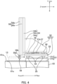
- FIG. 4 is a side view of the tool conveyance mechanism 50 as viewed from the left side.
- FIG. 5 is a front view of the tool conveyance mechanism 50 as viewed from the front side.
- the tool conveyance mechanism 50 includes a left-right movable base 51, an up-and-down and back-and-forth unit 52, an X-axis motor M1 (see FIG. 5 ), a Z-axis cylinder 57, and a Y-axis motor M2.
- the up-and-down and back-and-forth unit 52 is supported by the left-right movable base 51.
- the X-axis motor M1 drives the left-right movable base 51 in the left-right direction (X-axis direction).
- the Z-axis cylinder 57 drives the up-and-down and back-and-forth unit 52 in the front-rear direction (Z-axis direction).
- the Y-axis motor M2 drives extension and shortening of an up-and-down slider 58, which is arranged on the up-and-down and back-and-forth unit 52, in the up-down direction (Y-axis direction).
- the left-right movable base 51 is composed of a rectangular plate with the longitudinal side along the front-rear direction.
- the left-right movable base 51 is movable in the left-right direction along a pair of guide rails 20.
- the pair of guide rails 20 is formed on the top of a support member 21.
- the support member 21 is arranged on the third cover unit 63 of the machine tool 1.
- the support member 21 has a horizontal plate part 21a and a pair of legs 21b.
- the horizontal plate part 21a extends throughout the length of the third cover unit 63 in the left-right direction.
- the pair of legs 21b supports the ends of the horizontal plate part 21a.
- the left-right movable base 51 is supported via sliders 53 on the pair of guide rails 20.
- the sliders 53 are respectively engaged with the guide rails 20 and are movable in the left-right direction.
- the left-right movable base 51 moves in the left-right direction along the pair of guide rails 20 along with the sliders 53.
- the X-axis motor M1 is fixed to the left end of the left-right movable base 51.
- the X-axis motor M1 is arranged with an output shaft thereof directed vertically downward.
- the output shaft of the X-axis motor M1 has a pinion gear attached to the distal end thereof.
- the guide rail 20 located on the front side has a rack bar attached to a side surface thereof.
- the rack bar extends throughout the length of the guide rail 20 in the left-right direction and meshes with the pinion gear.
- the X-axis motor M1 rotates the pinion gear meshing with the rack bar, thereby driving the left-right movable base 51 in the left-right direction along with the pinion gear.
- the X-axis motor M1 is operationally controlled by the controller 100 that is described later.
- the left-right movable base 51 has a pair of left and right guide rails 55 (only one of which is shown in FIG. 4 ) on the top thereof.
- the pair of guide rails 55 guides the up-and-down and back-and-forth unit 52 such that the up-and-down and back-and-forth unit 52 is movable in the front-rear direction.
- the pair of guide rails 55 extends almost throughout the length of the left-right movable base 51 in the front-rear direction on the top of the left-right movable base 51.
- the up-and-down and back-and-forth unit 52 has a base member 54 and the up-and-down slider 58.
- the base member 54 has an L-shape as viewed in the left-right direction.
- the up-and-down slider 58 is attached to the base member 54.
- the base member 54 has a horizontal plate 54a, a vertical plate 54b, and a pair of ribs 54c (only one of which is shown in FIG. 4 ).
- the horizontal plate 54a has a rectangular shape with the longitudinal side along the front-rear direction.
- the vertical plate 54b extends upward from the front edge of the horizontal plate 54a.
- the ribs 54c each have a substantially trapezoidal plate shape and respectively connect the left and right edges of the horizontal plate 54a to a rear surface of the vertical plate 54b.
- the horizontal plate 54a of the base member 54 is supported via sliders 56 on the pair of left and right guide rails 55 arranged on the top of the left-right movable base 51.
- the sliders 56 are arranged two by two on the guide rails 55, i.e., four sliders 56 in total are arranged on the guide rails 55.
- the sliders 56 are engaged with the guide rails 55 and are movable in the front-rear direction.
- the base member 54 is movable in the front-rear direction along the pair of guide rails 55 along with the sliders 56.
- the Z-axis cylinder 57 drives back-and-forth movement of the up-and-down and back-and-forth unit 52 as a whole in the front-rear direction.
- the Z-axis cylinder 57 is composed of a hydraulic cylinder that hydraulically drives a rod 57a in the front-rear direction (Z-axis direction).
- the distal end of the rod 57a is fixed to a bottom surface of the base member 54 of the up-and-down and back-and-forth unit 52.
- the Z-axis cylinder 57 is operationally controlled by switching between hydraulic flow paths of a hydraulic pressure supply device, not illustrated, by the controller 100.
- the up-and-down slider 58 is attached to a front surface of the vertical plate 54b of the base member 54.
- the up-and-down slider 58 has a two-stroke mechanism.
- the up-and-down slider 58 has a first slide unit 58a and a second slide unit 58b.
- the second slide unit 58b is arranged to overlap a front face of the first slide unit 58a.
- the first slide unit 58a and the second slide unit 58b are each formed in a rectangular plate shape with the longitudinal side along the up-down direction.
- the first slide unit 58a and the second slide unit 58b each have a rack plate fixed thereto that extends in the up-down direction.
- the first slide unit 58a and the second slide unit 58b overlap each other with a pinion gear meshing with the rack plates thereof.
- moving the first slide unit 58a downward causes the second slide unit 58b to slide downward relative to the first slide unit 58a moving downward, whereby they are extended as a whole.
- moving the first slide unit 58a upward causes the second slide unit 58b to move upward relative to the first slide unit 58a moving upward, whereby they are shortened as a whole.
- the amount of stroke of the up-and-down slider 58 as extended is doubled without increase in the length of the up-and-down slider 58 as shortened.
- the Y-axis motor M2 (see FIG. 5 ) is a drive source for driving up-and-down movement of the up-and-down slider 58.
- the Y-axis motor M2 is supported to be movable in the up-down direction with respect to the base member 54.
- the Y-axis motor M2 is arranged such that its output shaft horizontally extends in the left-right direction.
- the Y-axis motor M2 drives up-and-down movement of the first slide unit 58a in the up-down direction via a gear mechanism.
- the second slide unit 58b is driven and moved up and down in conjunction with the first slide unit 58a being driven and moved up and down by the Y-axis motor M2.
- the Y-axis motor M2 is operationally controlled by the controller 100 that is described later.
- the second slide unit 58b of the up-and-down slider 58 has at the lower end thereof a tool holding unit 59 for holding a long-length tool T2.
- the tool holding unit 59 has an engagement plate 59b and a lock mechanism.
- the engagement plate 59b has an engagement portion 59a having an arcuate shape which is open to the right side as illustrated in FIG. 5 .
- the lock mechanism includes a lock plate 59c.
- the lock plate 59c is supported at a portion above the engagement portion 59a on the engagement plate 59b such that it is turnable about a shaft 59d as the fulcrum.
- the lock mechanism switches the lock plate 59c between a locking position and an unlocking position by controlling the supply of hydraulic pressure to a hydraulic flow path formed in the engagement plate 59b. When switched into the locking position, the lock plate 59c turns clockwise in FIG.
- the tool conveyance mechanism 50 is configured to be able to move the tool holding unit 59 arranged at the lower end of the up-and-down slider 58 to a stand-by position (see FIG. 2 ), a tool change position (see FIG. 6 ), a stocker position (see FIG. 7 ), and a position for work (see FIG. 8 ) by combining movement of the left-right movable base 51 in the left-right direction and up-and-down movement (extension and shortening) of the up-and-down slider 58 in the up-down direction.
- the stand-by position is a position for the tool holding unit 59 to wait until a request of conveyance of a tool T2 is made to the tool conveyance mechanism 50.
- FIG. 2 shows a state where the tool holding unit 59 is positioned at the stand-by position.
- the tool holding unit 59 at the stand-by position is situated directly above the first opening 61e formed in the ceiling cover 61a.
- the position in the left-right direction (X-axis direction) and the front-rear direction (Z-axis direction) of the stand-by position is set such that a long-length tool T2 held by the tool holding unit 59 passes through the first opening 61e without interference with the first opening 61e when the tool holding unit 59 is moved downward in the Y-axis direction from the stand-by position into the machining chamber A by the up-and-down slider 58.
- the position in the height direction of the stand-by position is set such that the lower end of the tool holding unit 59 is situated at a position higher than the tool pots 81 of the long-length tool stocker 8.
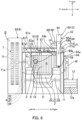
- the tool change position is a position for transferring a tool T2 between the spindle 2 and the tool holding unit 59.
- FIG. 6 shows a state where the tool holding unit 59 is positioned at the tool change position.
- a tool T2 attached to the spindle 2 enters and engages the engagement portion 59a and thereby the engagement portion 59a is arranged coaxially with the spindle 2.
- the transfer (insertion and pulling) of a tool T2 between the tool holding unit 59 and the spindle 2 is carried out by back-and-forth movement in the Z-axis direction by the Z-axis cylinder 57 and reciprocation in the X-axis direction by the X-axis motor M1.
- a position the tool holding unit 59 reaches when moved slightly leftward in the X-axis direction to release the tool T2 from the engagement portion 59a is designated as an approach position.
- the stocker position is a position for transferring a tool T2 between the long-length tool stocker 8 and the tool holding unit 59.
- FIG. 7 shows an example state where the tool holding unit 59 is positioned at the stocker position.
- a tool T2 attached to the tool pot 81 of the long-length tool stocker 8 enters and engages the engagement portion 59a and thereby the engagement portion 59a is arranged coaxially with the tool pot 81.
- three tool pots 81 are provided, three stocker positions in total are set respectively corresponding to the three tool pots 81. In the example shown in FIG.
- the tool holding unit 59 is positioned at the stocker position set corresponding to the leftmost one of the tool pots 81.
- the transfer (insertion and pulling) of a tool T2 between the tool holding unit 59 and the tool pot 81 is also carried out by back-and-forth movement in the Z-axis direction by the Z-axis cylinder 57 and reciprocation in the X-axis direction by the X-axis motor M1. Further, for each of the stocker positions, a position the tool holding unit 59 reaches when moved slightly leftward in the X-axis direction to release the tool T2 from the engagement portion 59a is designated as an approach position.
- the position for work is a position for allowing a worker W to access the tool holding unit 59 from the top of the platform 12 (predetermined working area) provided on the right of the machine tool 1 to perform attachment/removal of a tool T2.
- FIG. 8 shows a state where the tool holding unit 59 is positioned at the position for work.
- the tool holding unit 59 positioned at the position for work is situated directly below the second opening 64c formed in the ceiling door part 64b of the movable door 64.
- the tool holding unit 59 positioned at the position for work is spaced slightly to the left from the right opening 61c.
- the tool holding unit 59 positioned at the position for work is preferably situated at a height nearly equal to the average adult male waist height.
- FIG. 9 is a block diagram partially illustrating a control system of the machine tool 1.
- the machine tool 1 includes a controller 100.
- the controller 100 is composed of a computer including a CPU, a ROM, and a RAM.
- the controller 100 is connected to a machining mechanism unit 101, the standard tool changer 4, the long-length tool changer 5, a shutter drive unit 102, a main operation panel 103, and a setup operation unit 104 so as to transmit and receive signals to and from them.
- the machining mechanism unit 101 includes the feed drive mechanisms in the X-axis, Y-axis, and Z-axis directions, the drive mechanisms for the tilt table 31 and the turntable 33, and a spindle motor driving the spindle 2.
- the standard tool changer 4 performs the tool change for a standard-size tool T1 with the tool change arm 41 as described above.
- the controller 100 drives actuators (such as a drive motor for the tool change arm 41) for the standard tool changer 4, thereby causing the standard tool changer 4 to perform the tool change.
- the long-length tool changer 5 performs the tool change for a long-length tool T2 with the tool conveyance mechanism 50. This long-length tool changer 5 also performs setup in addition to the tool change, which is descried later.
- the controller 100 is electrically connected to actuators for the tool conveyance mechanism 50.
- the actuators for the tool conveyance mechanism 50 include, for example, the X-axis motor M1 driving the left-right movable base 51, the Y-axis motor M2 driving the up-and-down slider 58, and a flow path switching valve of the hydraulic pressure supply device connected to the Z-axis cylinder 57.
- the X-axis motor M1 and the Y-axis motor M2 change the position of the up-and-down and back-and-forth unit 52 in an X-axis and Y-axis plane, thereby changing the position of the tool holding unit 59 arranged at the lower end of the up-and-down slider 58 in the X-axis and Y-axis plane.
- the shutter drive unit 102 includes the driving actuator for the opening and closing shutter 13 for the first opening 61e formed in the ceiling cover 61a and the driving actuator for the opening and closing shutter 14 for the second opening 64c formed in the movable door 64.
- the controller 100 operationally controls these driving actuators.
- the main operation panel 103 has a cycle start button 103a for starting execution of an NC program and a touch panel 103b for a worker W to make various settings of the machine tool 1.
- the touch panel 103b displays thereon soft keys for the worker W to input an NC program and set buttons for setting the running mode of the machine tool 1.
- an option for the running mode of the machine tool 1 is an automatic running mode for machining a workpiece in accordance with an NC program.
- Another option for the running mode of the machine tool 1 is a setup mode for allowing the worker W to perform various setups.
- An example of the setups is setup of a tool T2 to be stored in the long-length tool stocker 8.
- the touch panel 103b has a setting screen for the worker W to specify the tool pot 81 holding the tool T2 as the setup target.
- the main operation panel 103 Upon accepting operation of the cycle start button 103a or the touch panel 103b, the main operation panel 103 transmits an operation signal for the operation to the controller 100.
- the setup operation unit 104 has a setup execution button 104a for causing the tool conveyance mechanism 50 to perform conveyance of a tool T2 with the setup mode set in the main operation panel 103.
- the setup execution button 104a is provided on a right side surface of the machine tool 1 so that it can be operated by the worker W standing on the top of the platform 12.
- the setup operation unit 104 Upon accepting operation of the setup execution button 104a, the setup operation unit 104 transmits an operation signal for the operation to the controller 100.
- the setup operation unit 104 and the main operation panel 103 are shown only in the brock diagram of FIG. 9 and omitted in the other perspective views and front views.
- the controller 100 Upon receiving the operation signal for the operation of the cycle start button 103a from the main operation panel 103, the controller 100 executes an NC program stored in a storage that is not illustrated. The controller 100 causes the machining mechanism unit 101 to carry out machining of a workpiece in accordance with the NC program. Upon extracting a change command for a standard-size tool T1 during the execution of the NC program, the controller 100 causes the standard tool changer 4 to carry out the tool change operation. In this tool change operation, the standard tool changer 4 performs tool change between the spindle 2 and the conveyance unit 42 with the tool change arm 41 as described above.
- the controller 100 Upon extracting a change command for a long-length tool T2 during the execution of the NC program, the controller 100 (an example of the conveyance control unit) causes the long-length tool changer 5 (the tool conveyance mechanism 50) to carry out the tool change operation. Upon receiving the operation signal for the operation of the setup execution button 104a from the setup operation unit 104, the controller 100 causes the long-length tool changer 5 (the tool conveyance mechanism 50) to carry out the setup operation.
- the tool change operation to be carried out by the long-length tool changer 5 is described in detail with reference to FIGS. 2 , 6 , and 7 .
- This tool change operation is started with the tool holding unit 59 positioned at the stand-by position as shown in FIG. 2 .
- the opening and closing shutter 13 mounted on the ceiling cover 61a of the machine tool 1 is moved to the open position by the shutter drive unit 102 under control by the controller 100.
- the first opening 61e located directly below the stand-by position for the tool holding unit 59 is opened.
- driving of the X-axis motor M1, the Y-axis motor M2, and the Z-axis cylinder 57 is controlled.
- the tool holding unit 59 is moved in the X-axis, Y-axis, and Z-axis directions so that the tool change operation is carried out.
- the tool holding unit 59 is first moved downward to a predetermined position through the first opening 61e.
- the predetermined position is the approach position for the tool change position.
- the tool holding unit 59 is moved rightward in the X-axis direction to be positioned at the tool change position (see FIG. 6 ). Thereby, a used tool T2 enters the engagement portion 59a of the engagement plate 59b.
- the lock plate 59c is switched into the locking position so that the used tool T2 is held by the tool holding unit 59. Subsequently, the tool holding unit 59 is moved frontward in the Z-axis direction so that the used tool T2 is pulled out frontward from a tool attachment hole of the spindle 2.
- the tool holding unit 59 is moved upward in the Y-axis direction to be moved out of the machining chamber A through the first opening 61e, and then is moved to the front of an empty tool pot 81 as a storage destination in the long-length tool stocker 8 (a position located in front of the stocker position for the empty tool pot 81 in the Z-axis direction) (see FIG. 7 ).
- the tool holding unit 59 is moved rearward in the Z-axis direction to the stocker position. Thereby, the used tool T2 held by the tool holding unit 59 is inserted into the empty tool pot 81.
- the lock plate 59c of the tool holding unit 59 is switched into the unlocking position.
- the tool holding unit 59 is moved leftward in the X-axis direction to the approach position so that the tool holding unit 59 is moved away from the stored used tool T2.
- the tool holding unit 59 is moved upward in the Y-axis direction to be positioned at the same height as the stand-by position, and then is moved to a position above the approach position for another tool pot 81 that holds a next tool T2. Subsequently, the tool holding unit 59 is moved downward in the Y-axis direction to the approach position and then is moved rightward in the X-axis direction to the stocker position for the tool pot 81. Thereby, the next tool T2 enters the engagement portion 59a of the engagement plate 59b. Thereafter, the lock plate 59c is switched into the locking position so that the next tool T2 is held by the tool holding unit 59. Subsequently, the tool holding unit 59 is moved frontward in the Z-axis direction so that the next tool T2 is pulled out from the tool pot 81.
- the tool holding unit 59 is moved to a position above the spindle 2 at which the held next tool T2 is situated in front of the spindle 2 in the Z-axis direction. Thereafter, the tool holding unit 59 is moved into the machining chamber A through the first opening 61e and positioned such that the next tool T2 held by the holding unit 59 is arranged coaxially with the spindle 2. Subsequently, the tool holding unit 59 is moved rearward in the Z-axis direction to the tool change position so that the next tool T2 held by the tool holding unit 59 is inserted into the tool attachment hole of the spindle 2.
- the lock plate 59c of the tool holding unit 59 is switched into the unlocking position. Subsequently, the tool holding unit 59 is moved leftward in the X-axis direction to the approach position. Thereby, the next tool T2 is transferred from the tool holding unit 59 to the spindle 2 and attached to the spindle 2. Subsequently, the tool holding unit 59 is moved upward in the Y-axis direction to be returned to the stand-by position (see FIG. 2 ). Thus, the tool change operation for replacing the used tool T2 attached to the spindle 2 with the next tool T2 is carried out. Upon completion of this tool change operation, the opening and closing shutter 13 is returned to the closed position by the shutter drive unit 102. Thereby, the first opening 61e is closed by the opening and closing shutter 13, so that the machining chamber A and the space located on the long-length tool stocker 8 side are completely separated.
- the controller 100 identifies, based on the operation signal received from the main operation panel 103, the tool pot 81 as the setup target (the tool pot 81 holding the tool T2 to be unloaded), which is specified by the worker W, from the thee tool pots 81 of the long-length tool stocker 8.
- the tool holding unit 59 is moved rightward in the X-axis direction from the stand-by position (see FIG. 2 ) to be positioned at a position above the approach position for the identified tool pot 81.
- the tool holding unit 59 is moved downward in the Y-axis direction to the approach position and then is moved rightward in the X-axis direction to the stocker position for the identified tool pot 81 (see FIG. 7 ).
- the tool T2 as the setup target enters the engagement portion 59a of the engagement plate 59b.
- the lock plate 59c of the tool holding unit 59 is switched into the locking position so that the tool T2 to be unloaded as the setup target is held by the tool holding unit 59.
- the tool holding unit 59 is moved frontward in the Z-axis direction so that the tool T2 to be unloaded is pulled out from the tool pot 81.
- the opening and closing shutter 14 mounted on the ceiling door part 64b of the movable door 64 is moved to the open position so that the second opening 64c formed in the ceiling door part 64b is opened (see FIG. 8 ).
- the tool holding unit 59 is moved from the stocker position (see FIG. 7 ) to a position above the position for work (see FIG. 8 ) located directly below the second opening 64c and then is moved downward to the position for work through the second opening 64c.
- the movable door 64 is locked by a lock device, not illustrated, under control by the controller 100 so as not to be moved until completion of the movement of the tool holding unit 59 to the position for work.
- the lock by the lock device is released by the controller 100 after the completion of the movement of the tool holding unit 59 to the position for work.
- the worker W can move the movable door 64 in the opening direction so as to perform work on the tool holding unit 59 positioned at the position for work (see FIG. 10 ).
- the second opening 64c formed in the ceiling door part 64b of the movable door 64 is open at the rear side in the Z-axis direction. Therefore, the ceiling door part 64b and the up-and-down slier 58 of the tool conveyance mechanism 50 do not interfere with each other when the movable door 64 is slid frontward to be opened.
- the worker W can remove the tool T2 to be unloaded as the setup target from the tool holding unit 59 positioned at the position for work and then attach a new tool T2 to the tool holding unit 59. Once the worker W presses the setup execution button 104a after completing the attachment of the new tool T2 to the tool holding unit 59, the setup operation (tool change operation) by the tool conveyance mechanism 50 is resumed.
- the tool holding unit 59 is moved to the front of the tool pot 81 that used to hold the unloaded tool T2 (the tool pot 81 identified by the controller 100). After moved thereto, the tool holding unit 59 is moved rearward in the Z-axis direction to the stocker position. Thereafter, the lock plate 59c of the tool holding unit 59 is switched into the unlocking position. Subsequently, the tool holding unit 59 is moved leftward in the X-axis direction to the approach position. Thereby, the new tool T2 is transferred from the tool holding unit 59 to the tool pot 81 and held by the tool pot 81. Thus, the setup operation for replacing the tool T2 to be unloaded with the new tool T2 is carried out. Where there are two or more tools T2 as the setup target, the above-described setup operation is carried out with respect to each of the tools T2.
- the worker W After completion of the setup operation, the worker W performs on the main operation panel 103 an operation for ending the setup mode (e.g., switching to the automatic running mode), so that the operation signal for the operation is transmitted from the main operation panel 103 to the controller 100.
- the controller 100 drives an XY movement actuator Mxy of the tool conveyance mechanism 50 to return the tool holding unit 59 to the stand-by position.
- the machine tool 1 includes the tool conveyance mechanism 50 that has the tool holding unit 59 for detachably holding a tool T2 and moves the tool holding unit 59 along the predetermined path.
- the tool conveyance mechanism 50 is configured to be able to move the tool holding unit 59 at least to the tool change position, the stocker position, and the position for work.
- the position for work is set at a position such that a worker W can perform attachment/removal of a tool T2 to/from the tool holding unit 59 from the top of the platform 12 (predetermined working area) provided on the right of the machine tool 1 (an example of the outside of the machine tool).
- the worker W can carry out setup of a tool T2 to the long-length tool stocker 8 by moving the tool holding unit 59 of the tool conveyance mechanism 50 to the position for work under control by the controller 100 and then performing attachment/removal of the tool T2 to/from the tool holding unit 59 (see FIG. 10 ). Therefore, the worker W does not need to enter the machining chamber A of the machine tool 1 or climb up to the top of the machine tool 1 and can easily and safely perform the setup of a tool T2 from the outside of the machine tool 1.
- the long-length tool stocker 8 n this embodiment is arranged outside the first cover unit 61 surrounding the machining chamber A. Specifically, the long-length tool stocker 8 is arranged on the top of the ceiling cover 61a covering the top of the machining chamber A.
- the long-length tool stocker 8 is arranged on the same floor as where the worker W works, it is necessary to provide a safety fens surrounding the area where the long-length tool stocker 8 is arranged or provide a human detection sensor for entry detection to prevent the worker W from accidently entering the area.
- the long-length tool stocker 8 is arranged on the top of the ceiling cover 61a of the machine tool 1 that is originally less likely to be approached by the worker W; therefore, the cost required for such safety measures is cut.
- the ceiling cover 61a in this embodiment has formed therein the first opening 61e for the tool holding unit 59 of the tool conveyance mechanism 50 to pass through when moved to the tool change position.
- the ceiling door part 64b in this embodiment has formed therein the second opening 64c for the tool holding unit 59 of the tool conveyance mechanism 50 to pass through when moved to the position for work.
- This configuration secures the movement path (the path between the tool change position, the stocker position, and the position for work) for the tool holding unit 59 with the long-length tool stocker 8 arranged on the top of the ceiling cover 61a.
- the machine tool 1 in this embodiment has the opening and closing shutter 13 opening and closing the first opening 61e and has the opening and closing shutter 14 opening and closing the second opening 64c. Opening and closing of these opening and closing shutters 13 and 14 are driven by the shutter drive unit 102.
- the first opening 61e and the second opening 64c can be closed by driving the opening and closing shutters 13 and 14, which prevents chips and coolant from scattering out of the machining chamber A through the first opening 61e and the second opening 64c.
- the machine tool 1 in this embodiment has the right opening 61c and the ceiling opening 61d as an opening for work that are respectively formed in the right side wall cover 61b (i.e., the side wall cover 61b adjacent to the working area set on the top of the platform 12) and the ceiling cover 61a connected to the right side wall cover 61b.
- the right opening 61c and the ceiling opening 61d are opened and closed by the movable door 64.
- the worker W when carrying out setup including attachment/removal of a heavy tool T2 to/from the tool holding unit 59 of the tool conveyance mechanism 50, the worker W can open the right opening 61c and the ceiling opening 61d by moving the movable door 64 frontward from the closed position to the open position (see FIG. 10 ), so that the worker W can carry out the setup using a hoisting device such as a crane through the opened ceiling opening 61d. Therefore, the physical load applied to the worker W in setup handling such a heavy tool T2 is reduced.
- the standard tool stocker 7 in this embodiment that stores standard-size tools T1 is arranged on the left of the machining chamber A.
- the position for work used for setup to the long-length tool stocker 8 is set on the side opposite to the tool magazines 71 (in this embodiment, on the right side) with the spindle 2 therebetween. Accordingly, for example, it is possible to allow a worker W to perform tool setup to the tool magazines 71 of the standard tool stocker 7 and at the same time allow another worker to perform tool setup to the long-length tool stocker 8.
- the long-length tool stocker 8 in this embodiment stores a long-length tool T2 that has a greater length than a tool T1 to be stored in the standard tool stocker 7.
- a long-length tool T2 is typically heavier than a standard-size tool T1; therefore, the physical load applied to the worker W in setup of a long-length tool T2 is greater than that in setup of a standard-size tool T1.
- the worker W can carry out setup of a long-length tool T2 by moving the tool holding unit 59 of the tool conveyance mechanism 50 to the position for work and performing attachment/removal of the tool T2 to/from the tool holding unit 59 instead of by performing work directly on the long-length tool stocker 8; therefore, the physical load applied to the worker W in the setup is reduced.
- FIG. 11 shows Embodiment 2 of the present invention.
- the position of the spindle 2 in positioning the tool holding unit 59 of the tool conveyance mechanism 50 at the tool change position is different from that in the above-described Embodiment 1.
- FIG. 11 shows the state where the tool holding unit 59 of the tool conveyance mechanism 50 is positioned at the tool change position and the state where the tool change arm 41 of the standard tool changer 4 is performing the tool change operation (performing a rotational movement), with these two states overlapping each other; however, these two states actually never occur at the same time.
- the position of the spindle 2 in moving the tool holding unit 59 of the tool conveyance mechanism 50 to the tool change position and transferring a tool T2 between the tool holding unit 59 and the spindle 2 and the position of the spindle 2 in causing the tool change arm 41 of the standard tool changer 4 to perform the tool change operation are set at the same position.
- the spindle 2 does not need to be changed in position. Therefore, the amount of movement of the spindle 2 (the amounts of feed in the feed drive mechanisms in the X-axis and the Y-axis) is reduced, which enables shortening of the cycle time.
- the long-length tool stocker 8 is constituted by a plurality of tool pots 81 arranged on the top of the ceiling cover 61a of the machine tool 1.
- the long-length tool stocker 8 is not limited to such a configuration.
- the long-length tool stocker 8 may be constituted by a rotary tool magazine similar to those of the standard tool stocker 7 or may be constituted by a plurality of tool holding units connected to each other by an endless chain so as to be rotationally movable.
- the tool conveyance mechanism 50 is configured to be able to move the tool holding unit 59 to the stand-by position, the tool change position, the stocker position, and the position for work.
- the stand-by position is not necessarily required.
- the stocker position may also serve as the stand-by position. That is to say, the tool conveyance mechanism 50 only needs to be configured to able to move the tool holding unit 59 at least to the tool change position, the stocker position, and the position for work.
- the transfer of a tool T2 between the spindle 2 and the tool holding unit 59 of the tool conveyance mechanism 50 is carried out by back-and-forth movement of the up-and-down and back-and-forth unit 52 in the front-rear direction by the Z-axis cylinder 57.
- the present invention is not limited to this configuration.
- the transfer of a tool T2 between the spindle 2 and the tool holding unit 59 may be carried out by moving the spindle 2 back and forth in the front-rear direction with the position of the tool holding unit 59 fixed.
- the transfer of a tool T2 between each tool pot 81 of the long-length tool stocker 8 and the tool holding unit 59 of the tool conveyance mechanism 50 is carried out by back-and-forth movement of the up-and-down and back-and-forth unit 52 in the front-rear direction by the Z-axis cylinder 57.
- the present invention is not limited to this configuration.
- the transfer of a tool T2 between each tool pot 81 and the tool holding unit 59 may be carried out by driving back-and-forth movement of the tool pot 81 in the front-rear direction with the position of the tool holding unit 59 fixed.
- the position for work to which the tool holding unit 59 is moved for setup of a tool T2 is set to be adjacent to the right opening 61a of the machine tool 1.
- the position for work is not limited to such a position and, for example, may be set to be adjacent to the front opening (not illustrated) of the machine tool 1.
- the controller 100 is configured to, in the setup mode, restrain opening and closing of the movable door 64 with the lock device until the tool holding unit 59 arrives at the position for work.
- the present invention is not limited to this configuration.
- the lock device for the movable door 64 may be eliminated.
- the opening of the movable door 64 for setup of a tool T2 is not limited to taking place after the movement of the tool holding unit 59 to the position for work and, for example, the worker W may open the movable door 64 prior to the movement of the tool holding unit 59 to the position for work.
- the machine tool 1 is composed of a horizontal machining center.
- the present invention is not limited to a horizontal machining center.
- the machine tool 1 may be composed of a lathe, a vertical machining center, or a combined machining machine capable of both turning and milling.
- the tool change operation and setup operation of the tool conveyance mechanism 50 are performed on a long-length tool T2.
- the present invention is not limited to this configuration.
- the tool change operation and setup operation of the tool conveyance mechanism 50 may be performed on a standard-size tool T1, so that standard-size tools T1 are stored in the long-length tool stocker 8.
- the long-length tool stocker 8 is arranged on the top of the ceiling cover 61a of the machine tool 1.
- the long-length tool stocker 8 is not limited to this arrangement and, for example, may be arranged on a side of the machine tool 1.
- the standard tool changer 4 performs the tool change with the tool change arm 41 with the conveyance unit 42 intervening between the tool magazines 71 and the spindle 2.
- the present invention is not limited to this configuration.
- the conveyance unit 42 may be eliminated, so that the standard tool changer 4 performs the tool change with the tool change arm 41 directly between the tool magazines 71 and the spindle 2.
Landscapes
- Engineering & Computer Science (AREA)
- Mechanical Engineering (AREA)
- Automatic Tool Replacement In Machine Tools (AREA)
Abstract
Description
- 0001 The present invention relates to a machine tool that includes a spindle detachably holding a tool, a tool stocker storing the tool to be attached to the spindle, a tool conveyance mechanism having a tool holding unit for detachably holding the tool and moving the tool holding unit along a predetermined path, and a conveyance control unit controlling the tool conveyance mechanism.
- 0002 A known example of the machine tool of this type is disclosed in
Japanese Unexamined Patent Application Publication No. H11-58161 - 0003 This machine tool includes a standard tool magazine, a large-sized tool magazine (tool stocker), and a tool conveyance mechanism. The standard tool magazine is affixed to a machine tool body. The large-sized tool magazine stores a long-length tool that is unable to be stored in the standard tool magazine. The tool conveyance mechanism conveys the long-length tool. The tool conveyance mechanism has a tool holding unit for holding the long-length tool. The tool holding unit is configured to be movable between a tool storage position set inside the large-sized tool magazine and a tool change position set inside a machining chamber. In automatic tool change for the long-length tool, the tool holding unit of the tool conveyance mechanism is moved to the tool change position under control by the conveyance control unit. After the tool holding unit has been moved to the tool change position, a spindle head is moved in X-axis, Y-axis, and Z-axis directions such that the tool held by the tool holding unit and the tool attached to the spindle are exchanged.
- 0004 Patent Literature 1: Japanese Unexamined Patent Application Publication No. H11-58161
- 0005 In the machine tool disclosed in the Patent Literature 1, the tool holding unit is movable to only two positions, namely, the tool change position set inside the machining chamber and the tool storage position (stocker position) set inside the large-sized tool magazine (tool stocker). This configuration requires a worker to directly access the tool stocker to perform setup of the tool to be stored in the tool stocker; therefore, there is the problem that the working efficiency of the tool setup is poor. In particular, in the case where the tool stocker is arranged on the ceiling of the machine tool as disclosed in Patent Literature 1, the worker has to perform work at a high place using a ladder or the like to access the tool stocker; therefore, the working efficiency is significantly poor.
- 0006 To avoid this problem, it may be possible to temporarily move the tool stored in the tool stocker to the tool change position with the tool conveyance mechanism in order to perform the tool setup. However, this operation requires the worker to enter the machining chamber, where the tool change position is set, to perform the tool setup. Therefore, in terms of providing high working efficiency and high safety, there is room for further improvement.
- 0007 The present invention has been achieved in view of the above-described circumstances, and an object of the invention is to provide a further improved machine tool which includes a spindle detachably holding a tool, a tool stocker storing the tool to be attached to the spindle, a tool conveyance mechanism having a tool holding unit for detachably holding the tool and moving the tool holding unit along a predetermined path, and a conveyance control unit controlling the tool conveyance mechanism and which enables easy and safe setup of the tool to be stored in the tool stocker.
- 0008 To solve the above-described problem, the present invention provides a machine tool at least including:
- a spindle arranged in a machining area and configured to detachably hold a tool; and
- a cover body formed by at least a ceiling cover and a side wall cover and surrounding the machining area to separate the machining area from outside, wherein:
- the machine tool includes:
- a tool stocker storing the tool to be attached to the spindle;
- a tool conveyance mechanism having a tool holding unit for detachably holding the tool and configured to move the tool holding unit along a predetermined path; and
- a conveyance control unit configured to control the tool conveyance mechanism; and
- the tool conveyance mechanism is configured to be able to move the tool holding unit at least to a tool change position, a stocker position, and a position for work.
- the machine tool includes:
- Note that the tool change position is a position for transferring the tool between the spindle and the tool holding unit, the stocker position is a position for transferring the tool between the tool stocker and the tool holding unit, and the position for work is set as a position for a worker to perform work on the tool holding unit from outside of the machining area.
- 0009 In this machine tool, the tool holding unit of the tool conveyance mechanism is movable at least to the tool change position, the stocker position, and the position for work under control by the conveyance control unit. The position for work is set as a position for a worker to perform work, such as attachment/removal of a tool, on the tool holding unit from outside of the machining area. Therefore, the worker can carry out tool setup to the tool stocker without performing work directly on the tool stocker. For example, the worker can carry out the tool setup to the tool stocker by moving the tool holding unit of the tool conveyance mechanism to the position for work under control by the conveyance control unit and performing attachment/removal of a tool on the tool holding unit and then causing the tool conveyance mechanism to store the tool held by the tool holding unit into the tool stocker. Thus, the worker does not need to enter the machining area (machining chamber) of the machine tool or access a less safe area (for example, a high place) and the worker can easily and safely perform the tool setup to the tool stocker from outside of the machine tool through operation of the tool conveyance mechanism.
- 0010 It is preferred that the tool stocker is arranged outside the cover body, especially, on top of the ceiling cover or above the ceiling cover.
- 0011 Arranging the tool stocker outside the cover body prevents coolant and chips scattering during workpiece machining from adhering to the tool stored in the tool stocker. Therefore, the tool is always kept clean, which enables avoidance of problems such as defects in attachment of the tool to the spindle and defects in workpiece cutting.
- 0012 Further, arranging the tool stocker on top of the ceiling cover or above the ceiling cover reduces the cost required for safety measures. For example, if the tool stocker is arranged on the same floor as where the worker works, it is necessary to provide a safety fens or a human detection sensor for entry detection to prevent the worker from accidentally entering the area where the tool stocker is arranged. Arranging the tool stocker on top of or above the ceiling cover of the machine tool, which are originally less likely to be approached by the worker, cuts the cost required for such safety measures.
- 0013 It is preferred that: the tool change position and the position for work are set inside the machining area; the tool conveyance mechanism is arranged to be located above the ceiling cover; and the ceiling cover has formed therein a first opening for the tool holding unit of the tool conveyance mechanism to pass through when moved to the tool change position and has formed therein a second opening for the tool holding unit to pass through when moved to the position for work.
- 0014 In this configuration, the tool holding unit of the tool conveyance mechanism is able to move to the tool change position through the first opening formed in the ceiling cover. Further, the tool holding unit of the tool conveyance mechanism is able to move to the operation for work through the second opening formed in the ceiling cover. Forming these first and second openings in the ceiling cover secures the movement path (the path between the tool change position, the stocker position, and the position for work) for the tool holding unit with the tool stocker arranged outside the cover body.
- 0015 It is preferred that: the position for work is set inside the machining area adjacent to the side wall cover; the side wall cover and the ceiling cover adjacent to the position for work respectively have third openings formed therein and the third openings are connected to each other; the machine tool further includes a movable door configured to open and close the third openings by linear sliding movement; the movable door has a door body part opening and closing the third opening formed in the side wall cover and a ceiling door part connected to an upper end of the door body part and opening and closing the third opening formed in the ceiling cover; and the second opening is formed in the ceiling door part.
- 0016 In this configuration, when the movable door is moved from a closed position to an open position, the door body part and the ceiling door part connected to the upper end of the door body part slide together and thereby the third openings formed in the ceiling cover and side wall cover of the machine tool are opened. Therefore, the worker can perform loading/unloading of an object into/from the machining area using a hoisting device such as a crane through the third openings as necessary. Thus, the worker can use a hoisting device in performing attachment/removal of a tool on the tool holding unit of the tool conveyance mechanism positioned at the operation for work, thereby reducing the physical load applied to his/her arms and waist.
- 0017 It is preferred that the machine tool further includes a first opening and closing mechanism configured to open and close the first opening and a second opening and closing mechanism configured to open and close the second opening.
- 0018 In this configuration, for example, closing the first opening and the second opening with the first opening and closing mechanism and the second opening and closing mechanism in machining a workpiece in the machining area prevents chips produced in the machining and coolant from scattering out of the machining area.
- 0019 It is preferred that: the machine tool includes the tool stocker as a first tool stocker and further includes a second tool stocker different from the first tool stocker; the second tool stocker has a plurality of tool holding units connected successively and is configured to detachably hold a tool in each of the tool holding units; the machine tool further includes a tool changer configured to perform tool change between the spindle and the second tool stocker; and the position for work is set on a side opposite to the second tool stocker with the spindle therebetween.
- 0020 In this configuration, it is possible to carry out the tool setup to the first tool stocker without hindering tool setup to the second tool stocker.
- 0021 Further, it is preferred that the first tool stocker is configured to be able to store a tool having a greater length than the tool to be stored in the second tool stocker.
- 0022 Most long-length tools are heavier than standard tools; therefore, the physical load applied to the worker in setup of a long-length tool is greater than that in setup of a standard tool. In this configuration, setup of a long-length tool is carried out using the tool conveyance mechanism; therefore, the physical load applied to the worker in the setup is reduced.
- 0023 It is preferred that a position of the spindle when the tool is transferred between the tool holding unit of the tool conveyance mechanism at the tool change position and the spindle and a position of the spindle when the tool changer performs the tool change are set at a same position.
- 0024 In this configuration, it is not necessary to change the position of the spindle in causing the tool changer to pull out a used tool from the spindle and then moving the tool holding unit of the tool conveyance mechanism to the tool change position to attach a tool to be used next to the spindle; therefore, this tool change is carried out quickly.
- 0025 As described above, the machine tool according to the present invention is configured such that the tool conveyance mechanism is able to move the tool holding unit at least to the tool change position, the stocker position, and the position for work, which enables tool setup to the tool stocker to be carried out easily and safely.
- 0026
-
FIG. 1 is a perspective view illustrating a machine tool according to Embodiment 1; -
FIG. 2 is a front view showing a state where a tool holding unit of a tool conveyance mechanism is positioned at a stand-by position; -
FIG. 3 is a top view of an opening and closing mechanism for opening and closing a right opening of the machine tool; -
FIG. 4 is a right side view of the tool conveyance mechanism; -
FIG. 5 is a front view of the tool conveyance mechanism; -
FIG. 6 is a front view showing a state where the tool holding unit of the tool conveyance mechanism is positioned at a tool change position; -
FIG. 7 is a front view showing a state where the tool holding unit of the tool conveyance mechanism is positioned at a stocker position; -
FIG. 8 is a front view showing a state where the tool holding unit of the tool conveyance mechanism is positioned at a position for work; -
FIG. 9 is a block diagram illustrating a configuration of a control system of the machine tool; -
FIG. 10 is a view similar toFIG. 1 but showing a state where the tool holding unit of the tool conveyance mechanism is positioned at the position for work; and -
FIG. 11 is a view similar toFIG. 6 but illustrating a machine tool according toEmbodiment 2. - 0027 Hereinafter, specific embodiments of the present invention will be described with reference to the drawings.
- 0028
-
FIG. 1 is a perspective view illustrating a machine tool 1 according to Embodiment 1.FIG. 2 is a schematic diagram illustrating the machine tool 1 as viewed from the front side thereof. The terms "front", "rear", "left", and "right" in the following description are defined with respect to the machine tool 1 unless otherwise indicated (refer to the directional axes shown in the figures). In the figures, plate-shaped elements are sometimes depicted with the thickness thereof omitted and cross sections thereof are sometimes depicted with no hatching. - 0029 The machine tool 1 is a horizontal machining center that includes a
spindle 2, a workpiece support device 3, astandard tool changer 4, a long-length tool changer 5, anouter cover 6, and a controller 100 (illustrated only inFIG. 9 ). Thespindle 2 is arranged to horizontally protrude into a machining chamber A as a machining area located in the front area of the machine tool 1. The workpiece support device 3 is arranged in the machining chamber A to support a workpiece that is not illustrated. Theouter cover 6 serves as a cover body that covers the entire machine tool 1. Thecontroller 100 operationally controls the entire machine tool 1. Note thatFIG. 1 shows the machine tool 1 with the front face thereof omitted. In actual, the machine tool 1 has on the front face thereof theouter cover 6 and an opening and closing door (not illustrated) mounted on theouter cover 6. - 0030 As illustrated in
FIG. 2 , thestandard tool changer 4 is a typical magazine-type automatic tool changer. Thestandard tool changer 4 performs tool change between astandard tool stocker 7 arranged at the left end in the machine tool 1 and thespindle 2. The long-length tool changer 5 performs tool change between a long-length tool stocker 8 arranged on the top of the machine tool 1 and thespindle 2 with atool conveyance mechanism 50 that is described later. The long-length tool stocker 8 stores a long-length tool T2 that has a size exceeding the tool size allowed for thestandard tool stocker 7. Examples of the long-length tool T2 include a line boring bar. The long-length tool stocker 8 corresponds to the first tool stocker. Thestandard tool stocker 7 corresponds to the second tool stocker. - 0031 The
spindle 2 is rotatably held by aspindle head 9. Thespindle head 9 is held by a column, not illustrated, erected on a rear end of abed 11 and is movable in an up-down direction (Y-axis direction). The column is supported on the top of the rear end of thebed 11 and is movable in a left-right direction (X-axis direction). This configuration enables thespindle head 9 to move in an X-axis and Y-axis plane. Movements of thespindle head 9 in the X-axis direction and in the Y-axis direction are each carried out by a feed drive mechanism (not illustrated) including a ball screw and a servo motor driving the ball screw. - 0032 The
spindle head 9 protrudes into the machining chamber A by penetrating through aprotective cover 10 arranged on the front side of the column. Theprotective cover 10 is arranged to separate the machining chamber A and a column-side space (not illustrated) receiving the entire column and the base end side of thespindle head 9. Theprotective cover 10 is configured by connecting a plurality of cover panels (not illustrated) to a pantograph mechanism (not illustrated) arranged behind the cover planes. Accordingly, theprotective cover 10 separates the machining chamber A and the column-side space while allowing thespindle head 9 to move in the X-axis and Y-axis plane. - 0033 The workpiece support device 3 supports a workpiece (not illustrated) to be machined. Specifically, the workpiece support device 3 has a tilt table 31, a
support base 32, and a turntable 33. The tilt table 31 is supported by thesupport base 32 and is swingable about the X-axis. The turntable 33 is arranged on the top of the tilt table 31. On the top of the turntable 33, a pallet P for attaching a workpiece thereto is fixed by clamping. Thesupport base 32 is supported on the top of a front end of thebed 11 and is movable in a front-rear direction (Z-axis direction). The movement of thesupport base 32 in the Z-axis direction is carried out by a feed drive mechanism (not illustrated) including a ball screw and a servo motor driving the ball screw. - 0034 In machining a workpiece, the feed drive mechanisms in the X-axis direction, the Y-axis direction, and the Z-axis direction and drive mechanisms for the tilt table 31 and the turntable 33 are controlled by the
controller 100, so that relative positional relation between the workpiece and a tool T1 or tool T2 attached to the distal end of thespindle 2 is controlled. Thereby, the workpiece is machined into a desired shape. - 0035
- The
outer cover 6 has afirst cover unit 61, asecond cover unit 62, and athird cover unit 63. Thefirst cover unit 61 includes aceiling cover 61a and a rightside wall cover 61b that are formed to surround the machining chamber A. Thesecond cover unit 62 covers a stocker receiving space B that receives thestandard tool stocker 7. Thethird cover unit 63 covers the column-side space (not illustrated) that receives the entire column and the base end side of thespindle head 9. - 0036 The
first cover unit 61 includes another side wall cover (not illustrated) arranged on the front side. This front side wall cover has a front opening formed therein through which operations such as loading/unloading of a workpiece are performed. This front opening is opened and closed by a movable door (not illustrated) that is slidable in the left-right direction. - 0037 The right
side wall cover 61b of thefirst cover unit 61 has a right opening 61c (seeFIG. 10 ) formed therein that corresponds to the third opening through which setup of a tool T2 to be stored in the long-length tool stocker 8 is performed. The right opening 61c is formed at a position higher than the floor on which the machine tool 1 is installed. Accordingly, aplatform 12 is provided on the right of the machine tool 1 to form a scaffold at the same height as the lower end position of the right opening 61c. Theplatform 12 has formed on the front face thereof steps 12a for a worker W to walk up to the top (scaffold) of theplatform 12. The top of theplatform 12 corresponds to the predetermined working area. - 0038 The right opening 61c has a rectangular shape with the top side opened as viewed from the right side of the machine tool 1 (see
FIG. 10 ). The top-side end of the right opening 61c connects to aceiling opening 61d formed in theceiling cover 61a of thefirst cover unit 61. Theceiling cover 61a is arranged to cover the top of the machining chamber A, and theceiling opening 61d is formed in the right end of theceiling cover 61a. Theceiling opening 61d has a rectangular shape with the right side opened as viewed from the top side. - 0039 The right opening 61c and the
ceiling opening 61d are opened and closed by a singlemovable door 64 that is slidable in the front-rear direction. Themovable door 64 has adoor body part 64a and aceiling door part 64b. Thedoor body part 64a opens and closes the right opening 61c. Theceiling door part 64b opens and closes theceiling opening 61d. Thedoor body part 64a is composed of a vertically extending rectangular plate and has awindow 64d in the vicinity of the center thereof. Thewindow 64d is closed by a transparent plate. Theceiling door part 64b has a rectangular plate shape and horizontally protrudes leftward from the top-side edge of thedoor body part 64a. - 0040 As illustrated in
FIG. 3 , theceiling door part 64b of themovable door 64 has anopening 64c as the second opening formed therein. Theopening 64c allows an up-and-downslider 58 of thetool conveyance mechanism 50, which is described later, to pass therethrough. Theopening 64c is formed in a rectangular shape extending in the front-rear direction with the rear side opened. Theopening 64c is opened and closed by an opening and closing shutter 14 (an example of the opening and closing member) that is slidable in the left-right direction. The opening and closingshutter 14 is mounted on the top of theceiling door part 64b together with a driving actuator therefor. The opening and closingshutter 14 and the driving actuator constitute the second opening and closing mechanism. The driving actuator is operationally controlled by thecontroller 100 that is described later. - 0041 When the
movable door 64 is positioned at a closed position as shown inFIG. 1 , theceiling opening 61d formed in theceiling cover 61a is closed by theceiling door part 64b and the right opening 61c formed in theside wall cover 61b is closed by thedoor body part 64a. When themovable door 64 is moved frontward to be positioned at an open position as shown inFIG. 10 , both theceiling opening 61d formed in theceiling cover 61a and the right opening 61c formed in theside wall cover 61b are opened. - 0042
Three tool pots 81 as constituent elements of the long-length tool stocker 8 are arranged on the left of theceiling opening 61d on the top of theceiling cover 61a. These threetool pots 81 are arranged at regular intervals in the left-right direction. The number oftool pots 81 in this example is three; however, the present invention is not limited thereto. The number oftool pots 81 may be two or less or may be four or more. - 0043 Each
tool pot 81 has a pot body and a trapezoidal support supporting the pot body from below. The pot body has a tool insertion hole that is open to the front side and receives a shank of a tool T2. For example, the pot body has a built-in tool holding mechanism using a spring. This tool holding mechanism removably holds the shank of the tool T2 inserted in the tool insertion hole of the pot body. - 0044 The
ceiling cover 61a has anopening 61e as the first opening formed therein on the left of the long-length tool stocker 8. Theopening 61e allows the up-and-downslider 58 of thetool conveyance mechanism 50, which is described later, to pass therethrough. Theopening 61e is opened and closed by an opening and closing shutter 13 (an example of the opening and closing member) that is slidable in the front-rear direction. The opening and closingshutter 13 is mounted on the top of theceiling cover 61a together with a driving actuator therefor. The opening and closingshutter 13 and the driving actuator constitute the first opening and closing mechanism. The driving actuator is operationally controlled by thecontroller 100 that is described later. In the following description, theopening 61e formed in theceiling cover 61a and theopening 64c formed in theceiling door part 64b of themovable door 64 are referred to as "thefirst opening 61e" and "thesecond opening 64c", respectively. - 0045 Referring to
FIG. 2 , the stocker receiving space B covered by thesecond cover unit 62 receives twotool magazines 71 that are of a rotary type and constitute thestandard tool stocker 7. - 0046 The two
tool magazines 71 are arranged coaxially with each other with a distance therebetween in the left-right direction. Eachtool magazine 71 consists of a disk-shaped magazine frame and a large number oftool holding units 71a arranged adjacent to each other in the circumferential direction on the outer peripheral edge of the magazine frame. Eachtool holding unit 71a has a groove shape which is open to the right side. Eachtool holding unit 71a is configured to detachably hold a standard-size tool T1. Note that the tool magazine is not limited to this configuration and may employ any conventionally known configuration, for example, may have a configuration in which tool holding units are connected to each other by an endless chain so as to be rotationally movable. - 0047
- The
standard tool changer 4 performs tool change between eachtool magazine 71 and thespindle 2 under control by thecontroller 100. Specifically, thestandard tool changer 4 has a tool change arm 41, aconveyance unit 42, and aconveyance rail 43. - 0048 The tool change arm 41 is received by an arm receiving space C that is located between the stocker receiving space B and the machining chamber A. The arm receiving space C and the machining chamber A are separated from each other by a
partition wall 61f. Thepartition wall 61f forms a left side wall of thefirst cover unit 61 surrounding the machining chamber A. Thepartition wall 61f has anopening 61g formed therein through which the arm receiving space C and the machining chamber A communicate with each other so that the tool change arm can enter the machining chamber A. Theopening 61g is openably closed by anATC shutter 44 that is slidable in the up-down direction. - 0049 The
conveyance rail 43 is arranged to extend in the left-right direction between a tool index position (predetermined angular position) in eachtool magazine 71 and a position in the left vicinity of the tool change arm 41. Theconveyance unit 42 conveys a next tool T1 indexed at the tool index position in eachtool magazine 71 to a conveyance end position set on the left of the tool change arm 41. Once theconveyance unit 42 arrives at the conveyance end position, theATC shutter 44 is opened and the tool change arm 41 rotates about its central support shaft as the fulcrum, thereby performing tool change for replacing a used tool T1 attached to thespindle 2 with the next tool T1 held by theconveyance unit 42. Through this tool change operation, the next tool T1 is attached to thespindle 2 and the used tool T1 is attached to theconveyance unit 42. Upon completion of the tool change operation by the tool change arm 41, theATC shutter 44 is closed and theconveyance unit 42 is moved leftward along theconveyance rail 43 to return the used tool T1 to a predetermined one of thetool holding units 71a of thetool magazines 71. - 0050
- The long-
length tool changer 5 has atool conveyance mechanism 50 for performing tool change between the long-length tool stocker 8 and thespindle 2. Thetool conveyance mechanism 50 waits above theceiling cover 61a of the machine tool 1 as shown inFIG. 1 while machining of a workpiece in accordance with an NC program is being performed. - 0051
FIG. 4 is a side view of thetool conveyance mechanism 50 as viewed from the left side.FIG. 5 is a front view of thetool conveyance mechanism 50 as viewed from the front side. Thetool conveyance mechanism 50 includes a left-rightmovable base 51, an up-and-down and back-and-forthunit 52, an X-axis motor M1 (seeFIG. 5 ), a Z-axis cylinder 57, and a Y-axis motor M2. The up-and-down and back-and-forthunit 52 is supported by the left-rightmovable base 51. The X-axis motor M1 drives the left-rightmovable base 51 in the left-right direction (X-axis direction). The Z-axis cylinder 57 drives the up-and-down and back-and-forthunit 52 in the front-rear direction (Z-axis direction). The Y-axis motor M2 drives extension and shortening of an up-and-downslider 58, which is arranged on the up-and-down and back-and-forthunit 52, in the up-down direction (Y-axis direction). - 0052 As illustrated in
FIGS. 1 and4 , the left-rightmovable base 51 is composed of a rectangular plate with the longitudinal side along the front-rear direction. The left-rightmovable base 51 is movable in the left-right direction along a pair of guide rails 20. The pair ofguide rails 20 is formed on the top of asupport member 21. Thesupport member 21 is arranged on thethird cover unit 63 of the machine tool 1. Thesupport member 21 has ahorizontal plate part 21a and a pair oflegs 21b. Thehorizontal plate part 21a extends throughout the length of thethird cover unit 63 in the left-right direction. The pair oflegs 21b supports the ends of thehorizontal plate part 21a. - 0053 As illustrated in
FIG. 4 , the left-rightmovable base 51 is supported viasliders 53 on the pair of guide rails 20. Thesliders 53 are respectively engaged with the guide rails 20 and are movable in the left-right direction. The left-rightmovable base 51 moves in the left-right direction along the pair ofguide rails 20 along with thesliders 53. - 0054 The X-axis motor M1 is fixed to the left end of the left-right
movable base 51. The X-axis motor M1 is arranged with an output shaft thereof directed vertically downward. The output shaft of the X-axis motor M1 has a pinion gear attached to the distal end thereof. Theguide rail 20 located on the front side has a rack bar attached to a side surface thereof. The rack bar extends throughout the length of theguide rail 20 in the left-right direction and meshes with the pinion gear. The X-axis motor M1 rotates the pinion gear meshing with the rack bar, thereby driving the left-rightmovable base 51 in the left-right direction along with the pinion gear. The X-axis motor M1 is operationally controlled by thecontroller 100 that is described later. - 0055 The left-right
movable base 51 has a pair of left and right guide rails 55 (only one of which is shown inFIG. 4 ) on the top thereof. The pair ofguide rails 55 guides the up-and-down and back-and-forthunit 52 such that the up-and-down and back-and-forthunit 52 is movable in the front-rear direction. The pair ofguide rails 55 extends almost throughout the length of the left-rightmovable base 51 in the front-rear direction on the top of the left-rightmovable base 51. - 0056 The up-and-down and back-and-forth
unit 52 has abase member 54 and the up-and-downslider 58. Thebase member 54 has an L-shape as viewed in the left-right direction. The up-and-downslider 58 is attached to thebase member 54. - 0057 The
base member 54 has ahorizontal plate 54a, avertical plate 54b, and a pair ofribs 54c (only one of which is shown inFIG. 4 ). Thehorizontal plate 54a has a rectangular shape with the longitudinal side along the front-rear direction. Thevertical plate 54b extends upward from the front edge of thehorizontal plate 54a. Theribs 54c each have a substantially trapezoidal plate shape and respectively connect the left and right edges of thehorizontal plate 54a to a rear surface of thevertical plate 54b. Thehorizontal plate 54a of thebase member 54 is supported viasliders 56 on the pair of left and right guide rails 55 arranged on the top of the left-rightmovable base 51. Thesliders 56 are arranged two by two on the guide rails 55, i.e., foursliders 56 in total are arranged on the guide rails 55. Thesliders 56 are engaged with the guide rails 55 and are movable in the front-rear direction. Thebase member 54 is movable in the front-rear direction along the pair ofguide rails 55 along with thesliders 56. - 0058 Between the pair of
guide rails 55 on the top of the left-rightmovable base 51, the Z-axis cylinder 57 is fixed. The Z-axis cylinder 57 drives back-and-forth movement of the up-and-down and back-and-forthunit 52 as a whole in the front-rear direction. The Z-axis cylinder 57 is composed of a hydraulic cylinder that hydraulically drives arod 57a in the front-rear direction (Z-axis direction). The distal end of therod 57a is fixed to a bottom surface of thebase member 54 of the up-and-down and back-and-forthunit 52. The Z-axis cylinder 57 is operationally controlled by switching between hydraulic flow paths of a hydraulic pressure supply device, not illustrated, by thecontroller 100. - 0059 The up-and-down
slider 58 is attached to a front surface of thevertical plate 54b of thebase member 54. In this embodiment, the up-and-downslider 58 has a two-stroke mechanism. Specifically, the up-and-downslider 58 has afirst slide unit 58a and asecond slide unit 58b. Thesecond slide unit 58b is arranged to overlap a front face of thefirst slide unit 58a. Thefirst slide unit 58a and thesecond slide unit 58b are each formed in a rectangular plate shape with the longitudinal side along the up-down direction. Thefirst slide unit 58a and thesecond slide unit 58b each have a rack plate fixed thereto that extends in the up-down direction. Thefirst slide unit 58a and thesecond slide unit 58b overlap each other with a pinion gear meshing with the rack plates thereof. In this two-stroke mechanism, moving thefirst slide unit 58a downward causes thesecond slide unit 58b to slide downward relative to thefirst slide unit 58a moving downward, whereby they are extended as a whole. On the other hand, moving thefirst slide unit 58a upward causes thesecond slide unit 58b to move upward relative to thefirst slide unit 58a moving upward, whereby they are shortened as a whole. Thus, as compared to a slider not using such a two-stroke mechanism, the amount of stroke of the up-and-downslider 58 as extended is doubled without increase in the length of the up-and-downslider 58 as shortened. - 0060 The Y-axis motor M2 (see
FIG. 5 ) is a drive source for driving up-and-down movement of the up-and-downslider 58. The Y-axis motor M2 is supported to be movable in the up-down direction with respect to thebase member 54. The Y-axis motor M2 is arranged such that its output shaft horizontally extends in the left-right direction. The Y-axis motor M2 drives up-and-down movement of thefirst slide unit 58a in the up-down direction via a gear mechanism. Since thefirst slide unit 58a is connected via the two-stroke mechanism to thesecond slide unit 58b as described above, thesecond slide unit 58b is driven and moved up and down in conjunction with thefirst slide unit 58a being driven and moved up and down by the Y-axis motor M2. The Y-axis motor M2 is operationally controlled by thecontroller 100 that is described later. - 0061 The
second slide unit 58b of the up-and-downslider 58 has at the lower end thereof atool holding unit 59 for holding a long-length tool T2. - 0062 As illustrated in
FIG. 5 , thetool holding unit 59 has anengagement plate 59b and a lock mechanism. Theengagement plate 59b has anengagement portion 59a having an arcuate shape which is open to the right side as illustrated inFIG. 5 . The lock mechanism includes alock plate 59c. Thelock plate 59c is supported at a portion above theengagement portion 59a on theengagement plate 59b such that it is turnable about ashaft 59d as the fulcrum. The lock mechanism switches thelock plate 59c between a locking position and an unlocking position by controlling the supply of hydraulic pressure to a hydraulic flow path formed in theengagement plate 59b. When switched into the locking position, thelock plate 59c turns clockwise inFIG. 5 about theshaft 59d as the fulcrum. Thereby, a tool T2 is interlocked with theengagement portion 59a by thelock plate 59c so as not to fall out. When switched into the unlocking position, thelock plate 59c rotates counterclockwise inFIG. 5 about theshaft 59d as the fulcrum. Thereby, a tool T2 can be horizontally inserted into or pulled out from theengagement portion 59a through the open right side of theengagement portion 59a. - 0063
- The
tool conveyance mechanism 50 is configured to be able to move thetool holding unit 59 arranged at the lower end of the up-and-downslider 58 to a stand-by position (seeFIG. 2 ), a tool change position (seeFIG. 6 ), a stocker position (seeFIG. 7 ), and a position for work (seeFIG. 8 ) by combining movement of the left-rightmovable base 51 in the left-right direction and up-and-down movement (extension and shortening) of the up-and-downslider 58 in the up-down direction. - 0064 The stand-by position is a position for the
tool holding unit 59 to wait until a request of conveyance of a tool T2 is made to thetool conveyance mechanism 50.FIG. 2 shows a state where thetool holding unit 59 is positioned at the stand-by position. Thetool holding unit 59 at the stand-by position is situated directly above thefirst opening 61e formed in theceiling cover 61a. - 0065 The position in the left-right direction (X-axis direction) and the front-rear direction (Z-axis direction) of the stand-by position is set such that a long-length tool T2 held by the
tool holding unit 59 passes through thefirst opening 61e without interference with thefirst opening 61e when thetool holding unit 59 is moved downward in the Y-axis direction from the stand-by position into the machining chamber A by the up-and-downslider 58. - 0066 Further, the position in the height direction of the stand-by position is set such that the lower end of the
tool holding unit 59 is situated at a position higher than thetool pots 81 of the long-length tool stocker 8. Thereby, the movement path for moving thetool holding unit 59 from the stand-by position to the stocker position is simplified so that the time required for the moving operation is reduced. - 0067 When the
tool holding unit 59 is positioned at the stand-by position, the up-and-down and back-and-forthunit 52 has been retracted by the Z-axis cylinder 57. Therefore, it is unnecessary to retract the up-and-down and back-and-forthunit 52 with the Z-axis cylinder 57 before moving thetool holding unit 59 from the stand-by position to the stocker position or the tool change position to cause thetool holding unit 59 to hold (engage) a tool T2. Consequently, the time required for thetool conveyance mechanism 50 to cause thetool holding unit 59 to hold the tool T2 is reduced. - 0068 The tool change position is a position for transferring a tool T2 between the
spindle 2 and thetool holding unit 59.FIG. 6 shows a state where thetool holding unit 59 is positioned at the tool change position. When thetool holding unit 59 is positioned at the tool change position, a tool T2 attached to thespindle 2 enters and engages theengagement portion 59a and thereby theengagement portion 59a is arranged coaxially with thespindle 2. The transfer (insertion and pulling) of a tool T2 between thetool holding unit 59 and thespindle 2 is carried out by back-and-forth movement in the Z-axis direction by the Z-axis cylinder 57 and reciprocation in the X-axis direction by the X-axis motor M1. Note that the position of thespindle 2 for this tool change is previously determined. Further, for this tool change position, a position thetool holding unit 59 reaches when moved slightly leftward in the X-axis direction to release the tool T2 from theengagement portion 59a is designated as an approach position. - 0069 The stocker position is a position for transferring a tool T2 between the long-
length tool stocker 8 and thetool holding unit 59.FIG. 7 shows an example state where thetool holding unit 59 is positioned at the stocker position. When thetool holding unit 59 is positioned at the stocker position, a tool T2 attached to thetool pot 81 of the long-length tool stocker 8 enters and engages theengagement portion 59a and thereby theengagement portion 59a is arranged coaxially with thetool pot 81. In this embodiment, since threetool pots 81 are provided, three stocker positions in total are set respectively corresponding to the threetool pots 81. In the example shown inFIG. 7 , thetool holding unit 59 is positioned at the stocker position set corresponding to the leftmost one of thetool pots 81. The transfer (insertion and pulling) of a tool T2 between thetool holding unit 59 and thetool pot 81 is also carried out by back-and-forth movement in the Z-axis direction by the Z-axis cylinder 57 and reciprocation in the X-axis direction by the X-axis motor M1. Further, for each of the stocker positions, a position thetool holding unit 59 reaches when moved slightly leftward in the X-axis direction to release the tool T2 from theengagement portion 59a is designated as an approach position. - 0070 The position for work is a position for allowing a worker W to access the
tool holding unit 59 from the top of the platform 12 (predetermined working area) provided on the right of the machine tool 1 to perform attachment/removal of a tool T2.FIG. 8 shows a state where thetool holding unit 59 is positioned at the position for work. Thetool holding unit 59 positioned at the position for work is situated directly below thesecond opening 64c formed in theceiling door part 64b of themovable door 64. Thetool holding unit 59 positioned at the position for work is spaced slightly to the left from the right opening 61c. Further, thetool holding unit 59 positioned at the position for work is preferably situated at a height nearly equal to the average adult male waist height. - 0071
-
FIG. 9 is a block diagram partially illustrating a control system of the machine tool 1. As illustrated inFIG. 9 , the machine tool 1 includes acontroller 100. Thecontroller 100 is composed of a computer including a CPU, a ROM, and a RAM. Thecontroller 100 is connected to amachining mechanism unit 101, thestandard tool changer 4, the long-length tool changer 5, ashutter drive unit 102, amain operation panel 103, and asetup operation unit 104 so as to transmit and receive signals to and from them. - 0072 The
machining mechanism unit 101 includes the feed drive mechanisms in the X-axis, Y-axis, and Z-axis directions, the drive mechanisms for the tilt table 31 and the turntable 33, and a spindle motor driving thespindle 2. - 0073 The
standard tool changer 4 performs the tool change for a standard-size tool T1 with the tool change arm 41 as described above. Thecontroller 100 drives actuators (such as a drive motor for the tool change arm 41) for thestandard tool changer 4, thereby causing thestandard tool changer 4 to perform the tool change. - 0074 The long-
length tool changer 5 performs the tool change for a long-length tool T2 with thetool conveyance mechanism 50. This long-length tool changer 5 also performs setup in addition to the tool change, which is descried later. Thecontroller 100 is electrically connected to actuators for thetool conveyance mechanism 50. The actuators for thetool conveyance mechanism 50 include, for example, the X-axis motor M1 driving the left-rightmovable base 51, the Y-axis motor M2 driving the up-and-downslider 58, and a flow path switching valve of the hydraulic pressure supply device connected to the Z-axis cylinder 57. The X-axis motor M1 and the Y-axis motor M2 change the position of the up-and-down and back-and-forthunit 52 in an X-axis and Y-axis plane, thereby changing the position of thetool holding unit 59 arranged at the lower end of the up-and-downslider 58 in the X-axis and Y-axis plane. - 0075 The
shutter drive unit 102 includes the driving actuator for the opening and closingshutter 13 for thefirst opening 61e formed in theceiling cover 61a and the driving actuator for the opening and closingshutter 14 for thesecond opening 64c formed in themovable door 64. Thecontroller 100 operationally controls these driving actuators. - 0076 The
main operation panel 103 has acycle start button 103a for starting execution of an NC program and atouch panel 103b for a worker W to make various settings of the machine tool 1. Thetouch panel 103b displays thereon soft keys for the worker W to input an NC program and set buttons for setting the running mode of the machine tool 1. For example, an option for the running mode of the machine tool 1 is an automatic running mode for machining a workpiece in accordance with an NC program. Another option for the running mode of the machine tool 1 is a setup mode for allowing the worker W to perform various setups. An example of the setups is setup of a tool T2 to be stored in the long-length tool stocker 8. Thetouch panel 103b has a setting screen for the worker W to specify thetool pot 81 holding the tool T2 as the setup target. Upon accepting operation of thecycle start button 103a or thetouch panel 103b, themain operation panel 103 transmits an operation signal for the operation to thecontroller 100. - 0077 The
setup operation unit 104 has asetup execution button 104a for causing thetool conveyance mechanism 50 to perform conveyance of a tool T2 with the setup mode set in themain operation panel 103. Thesetup execution button 104a is provided on a right side surface of the machine tool 1 so that it can be operated by the worker W standing on the top of theplatform 12. Upon accepting operation of thesetup execution button 104a, thesetup operation unit 104 transmits an operation signal for the operation to thecontroller 100. Note that thesetup operation unit 104 and themain operation panel 103 are shown only in the brock diagram ofFIG. 9 and omitted in the other perspective views and front views. - 0078 Upon receiving the operation signal for the operation of the
cycle start button 103a from themain operation panel 103, thecontroller 100 executes an NC program stored in a storage that is not illustrated. Thecontroller 100 causes themachining mechanism unit 101 to carry out machining of a workpiece in accordance with the NC program. Upon extracting a change command for a standard-size tool T1 during the execution of the NC program, thecontroller 100 causes thestandard tool changer 4 to carry out the tool change operation. In this tool change operation, thestandard tool changer 4 performs tool change between thespindle 2 and theconveyance unit 42 with the tool change arm 41 as described above. - 0079 Upon extracting a change command for a long-length tool T2 during the execution of the NC program, the controller 100 (an example of the conveyance control unit) causes the long-length tool changer 5 (the tool conveyance mechanism 50) to carry out the tool change operation. Upon receiving the operation signal for the operation of the
setup execution button 104a from thesetup operation unit 104, thecontroller 100 causes the long-length tool changer 5 (the tool conveyance mechanism 50) to carry out the setup operation. - 0080
- The tool change operation to be carried out by the long-
length tool changer 5 is described in detail with reference toFIGS. 2 ,6 , and7 . This tool change operation is started with thetool holding unit 59 positioned at the stand-by position as shown inFIG. 2 . First of all, the opening and closingshutter 13 mounted on theceiling cover 61a of the machine tool 1 is moved to the open position by theshutter drive unit 102 under control by thecontroller 100. Thereby, thefirst opening 61e located directly below the stand-by position for thetool holding unit 59 is opened. With thefirst opening 61e opened, driving of the X-axis motor M1, the Y-axis motor M2, and the Z-axis cylinder 57 is controlled. Thereby, thetool holding unit 59 is moved in the X-axis, Y-axis, and Z-axis directions so that the tool change operation is carried out. In the following description, only the operation of thetool holding unit 59 is described. Thetool holding unit 59 is first moved downward to a predetermined position through thefirst opening 61e. In this embodiment, the predetermined position is the approach position for the tool change position. Subsequently, thetool holding unit 59 is moved rightward in the X-axis direction to be positioned at the tool change position (seeFIG. 6 ). Thereby, a used tool T2 enters theengagement portion 59a of theengagement plate 59b. Thereafter, thelock plate 59c is switched into the locking position so that the used tool T2 is held by thetool holding unit 59. Subsequently, thetool holding unit 59 is moved frontward in the Z-axis direction so that the used tool T2 is pulled out frontward from a tool attachment hole of thespindle 2. - 0081 Subsequently, the
tool holding unit 59 is moved upward in the Y-axis direction to be moved out of the machining chamber A through thefirst opening 61e, and then is moved to the front of anempty tool pot 81 as a storage destination in the long-length tool stocker 8 (a position located in front of the stocker position for theempty tool pot 81 in the Z-axis direction) (seeFIG. 7 ). Subsequently, thetool holding unit 59 is moved rearward in the Z-axis direction to the stocker position. Thereby, the used tool T2 held by thetool holding unit 59 is inserted into theempty tool pot 81. Thereafter, thelock plate 59c of thetool holding unit 59 is switched into the unlocking position. Subsequently, thetool holding unit 59 is moved leftward in the X-axis direction to the approach position so that thetool holding unit 59 is moved away from the stored used tool T2. - 0082 Subsequently, the
tool holding unit 59 is moved upward in the Y-axis direction to be positioned at the same height as the stand-by position, and then is moved to a position above the approach position for anothertool pot 81 that holds a next tool T2. Subsequently, thetool holding unit 59 is moved downward in the Y-axis direction to the approach position and then is moved rightward in the X-axis direction to the stocker position for thetool pot 81. Thereby, the next tool T2 enters theengagement portion 59a of theengagement plate 59b. Thereafter, thelock plate 59c is switched into the locking position so that the next tool T2 is held by thetool holding unit 59. Subsequently, thetool holding unit 59 is moved frontward in the Z-axis direction so that the next tool T2 is pulled out from thetool pot 81. - 0083 Subsequently, the
tool holding unit 59 is moved to a position above thespindle 2 at which the held next tool T2 is situated in front of thespindle 2 in the Z-axis direction. Thereafter, thetool holding unit 59 is moved into the machining chamber A through thefirst opening 61e and positioned such that the next tool T2 held by the holdingunit 59 is arranged coaxially with thespindle 2. Subsequently, thetool holding unit 59 is moved rearward in the Z-axis direction to the tool change position so that the next tool T2 held by thetool holding unit 59 is inserted into the tool attachment hole of thespindle 2. - 0084 Thereafter, the
lock plate 59c of thetool holding unit 59 is switched into the unlocking position. Subsequently, thetool holding unit 59 is moved leftward in the X-axis direction to the approach position. Thereby, the next tool T2 is transferred from thetool holding unit 59 to thespindle 2 and attached to thespindle 2. Subsequently, thetool holding unit 59 is moved upward in the Y-axis direction to be returned to the stand-by position (seeFIG. 2 ). Thus, the tool change operation for replacing the used tool T2 attached to thespindle 2 with the next tool T2 is carried out. Upon completion of this tool change operation, the opening and closingshutter 13 is returned to the closed position by theshutter drive unit 102. Thereby, thefirst opening 61e is closed by the opening and closingshutter 13, so that the machining chamber A and the space located on the long-length tool stocker 8 side are completely separated. - 0085
- Next, the setup operation to be carried out by the
tool conveyance mechanism 50 of the long-length tool changer 5 is described in detail with reference toFIGS. 2 ,7 , and8 . In the setup operation, first of all, thecontroller 100 identifies, based on the operation signal received from themain operation panel 103, thetool pot 81 as the setup target (thetool pot 81 holding the tool T2 to be unloaded), which is specified by the worker W, from thethee tool pots 81 of the long-length tool stocker 8. Upon completion of the identification of thetool pot 81, thetool holding unit 59 is moved rightward in the X-axis direction from the stand-by position (seeFIG. 2 ) to be positioned at a position above the approach position for the identifiedtool pot 81. Subsequently, thetool holding unit 59 is moved downward in the Y-axis direction to the approach position and then is moved rightward in the X-axis direction to the stocker position for the identified tool pot 81 (seeFIG. 7 ). Thereby, the tool T2 as the setup target enters theengagement portion 59a of theengagement plate 59b. Thereafter, thelock plate 59c of thetool holding unit 59 is switched into the locking position so that the tool T2 to be unloaded as the setup target is held by thetool holding unit 59. Subsequently, thetool holding unit 59 is moved frontward in the Z-axis direction so that the tool T2 to be unloaded is pulled out from thetool pot 81. - 0086 Subsequently, the opening and closing
shutter 14 mounted on theceiling door part 64b of themovable door 64 is moved to the open position so that thesecond opening 64c formed in theceiling door part 64b is opened (seeFIG. 8 ). Subsequently, thetool holding unit 59 is moved from the stocker position (seeFIG. 7 ) to a position above the position for work (seeFIG. 8 ) located directly below thesecond opening 64c and then is moved downward to the position for work through thesecond opening 64c. - 0087 Note that the
movable door 64 is locked by a lock device, not illustrated, under control by thecontroller 100 so as not to be moved until completion of the movement of thetool holding unit 59 to the position for work. The lock by the lock device is released by thecontroller 100 after the completion of the movement of thetool holding unit 59 to the position for work. Thus, the worker W can move themovable door 64 in the opening direction so as to perform work on thetool holding unit 59 positioned at the position for work (seeFIG. 10 ). As illustrated inFIG. 3 , thesecond opening 64c formed in theceiling door part 64b of themovable door 64 is open at the rear side in the Z-axis direction. Therefore, theceiling door part 64b and the up-and-down slier 58 of thetool conveyance mechanism 50 do not interfere with each other when themovable door 64 is slid frontward to be opened. - 0088 The worker W can remove the tool T2 to be unloaded as the setup target from the
tool holding unit 59 positioned at the position for work and then attach a new tool T2 to thetool holding unit 59. Once the worker W presses thesetup execution button 104a after completing the attachment of the new tool T2 to thetool holding unit 59, the setup operation (tool change operation) by thetool conveyance mechanism 50 is resumed. - 0089 In the resumed setup operation, the
tool holding unit 59 is moved to the front of thetool pot 81 that used to hold the unloaded tool T2 (thetool pot 81 identified by the controller 100). After moved thereto, thetool holding unit 59 is moved rearward in the Z-axis direction to the stocker position. Thereafter, thelock plate 59c of thetool holding unit 59 is switched into the unlocking position. Subsequently, thetool holding unit 59 is moved leftward in the X-axis direction to the approach position. Thereby, the new tool T2 is transferred from thetool holding unit 59 to thetool pot 81 and held by thetool pot 81. Thus, the setup operation for replacing the tool T2 to be unloaded with the new tool T2 is carried out. Where there are two or more tools T2 as the setup target, the above-described setup operation is carried out with respect to each of the tools T2. - 0090 After completion of the setup operation, the worker W performs on the
main operation panel 103 an operation for ending the setup mode (e.g., switching to the automatic running mode), so that the operation signal for the operation is transmitted from themain operation panel 103 to thecontroller 100. Upon receiving the operation signal for ending the setup mode, thecontroller 100 drives an XY movement actuator Mxy of thetool conveyance mechanism 50 to return thetool holding unit 59 to the stand-by position. - 0091
- As described above, the machine tool 1 according to this embodiment includes the
tool conveyance mechanism 50 that has thetool holding unit 59 for detachably holding a tool T2 and moves thetool holding unit 59 along the predetermined path. Thetool conveyance mechanism 50 is configured to be able to move thetool holding unit 59 at least to the tool change position, the stocker position, and the position for work. The position for work is set at a position such that a worker W can perform attachment/removal of a tool T2 to/from thetool holding unit 59 from the top of the platform 12 (predetermined working area) provided on the right of the machine tool 1 (an example of the outside of the machine tool). - 0092 Accordingly, instead of by directly accessing the long-
length tool stocker 8, the worker W can carry out setup of a tool T2 to the long-length tool stocker 8 by moving thetool holding unit 59 of thetool conveyance mechanism 50 to the position for work under control by thecontroller 100 and then performing attachment/removal of the tool T2 to/from the tool holding unit 59 (seeFIG. 10 ). Therefore, the worker W does not need to enter the machining chamber A of the machine tool 1 or climb up to the top of the machine tool 1 and can easily and safely perform the setup of a tool T2 from the outside of the machine tool 1. - 0093 Further, the long-length tool stocker 8 n this embodiment is arranged outside the
first cover unit 61 surrounding the machining chamber A. Specifically, the long-length tool stocker 8 is arranged on the top of theceiling cover 61a covering the top of the machining chamber A. - 0094 This configuration prevents coolant and chips scattering during workpiece machining in the machining chamber A from adhering to the tools T2 stored in the long-
length tool stocker 8. Therefore, the tools T2 are always kept clean, which enables avoidance of the problems such as defects in attachment of the tools T2 to thespindle 2 and defects in workpiece cutting. Further, the arrangement of the long-length tool stocker 8 on the top of theceiling cover 61a achieves reduction of the cost required for safety measures. That is to say, for example, if the long-length tool stocker 8 is arranged on the same floor as where the worker W works, it is necessary to provide a safety fens surrounding the area where the long-length tool stocker 8 is arranged or provide a human detection sensor for entry detection to prevent the worker W from accidently entering the area. In this embodiment, the long-length tool stocker 8 is arranged on the top of theceiling cover 61a of the machine tool 1 that is originally less likely to be approached by the worker W; therefore, the cost required for such safety measures is cut. - 0095 Further, the
ceiling cover 61a in this embodiment has formed therein thefirst opening 61e for thetool holding unit 59 of thetool conveyance mechanism 50 to pass through when moved to the tool change position. Further, theceiling door part 64b in this embodiment has formed therein thesecond opening 64c for thetool holding unit 59 of thetool conveyance mechanism 50 to pass through when moved to the position for work. - 0096 This configuration secures the movement path (the path between the tool change position, the stocker position, and the position for work) for the
tool holding unit 59 with the long-length tool stocker 8 arranged on the top of theceiling cover 61a. - 0097 Further, the machine tool 1 in this embodiment has the opening and closing
shutter 13 opening and closing thefirst opening 61e and has the opening and closingshutter 14 opening and closing thesecond opening 64c. Opening and closing of these opening andclosing shutters shutter drive unit 102. - 0098 Accordingly, during workpiece machining in the machining chamber A, the
first opening 61e and thesecond opening 64c can be closed by driving the opening andclosing shutters first opening 61e and thesecond opening 64c. - 0099 Further, the machine tool 1 in this embodiment has the right opening 61c and the
ceiling opening 61d as an opening for work that are respectively formed in the rightside wall cover 61b (i.e., theside wall cover 61b adjacent to the working area set on the top of the platform 12) and theceiling cover 61a connected to the rightside wall cover 61b. The right opening 61c and theceiling opening 61d are opened and closed by themovable door 64. - 0100 Accordingly, when carrying out setup including attachment/removal of a heavy tool T2 to/from the
tool holding unit 59 of thetool conveyance mechanism 50, the worker W can open the right opening 61c and theceiling opening 61d by moving themovable door 64 frontward from the closed position to the open position (seeFIG. 10 ), so that the worker W can carry out the setup using a hoisting device such as a crane through the openedceiling opening 61d. Therefore, the physical load applied to the worker W in setup handling such a heavy tool T2 is reduced. - 0101 Further, the
standard tool stocker 7 in this embodiment that stores standard-size tools T1 is arranged on the left of the machining chamber A. The position for work used for setup to the long-length tool stocker 8 is set on the side opposite to the tool magazines 71 (in this embodiment, on the right side) with thespindle 2 therebetween. Accordingly, for example, it is possible to allow a worker W to perform tool setup to thetool magazines 71 of thestandard tool stocker 7 and at the same time allow another worker to perform tool setup to the long-length tool stocker 8. - 0102 Further, the long-
length tool stocker 8 in this embodiment stores a long-length tool T2 that has a greater length than a tool T1 to be stored in thestandard tool stocker 7. A long-length tool T2 is typically heavier than a standard-size tool T1; therefore, the physical load applied to the worker W in setup of a long-length tool T2 is greater than that in setup of a standard-size tool T1. In the machine tool 1 according to this embodiment, the worker W can carry out setup of a long-length tool T2 by moving thetool holding unit 59 of thetool conveyance mechanism 50 to the position for work and performing attachment/removal of the tool T2 to/from thetool holding unit 59 instead of by performing work directly on the long-length tool stocker 8; therefore, the physical load applied to the worker W in the setup is reduced. - 0103
-
FIG. 11 showsEmbodiment 2 of the present invention. In this Embodiment, the position of thespindle 2 in positioning thetool holding unit 59 of thetool conveyance mechanism 50 at the tool change position is different from that in the above-described Embodiment 1. For easy understanding of the following description about the position of thespindle 2,FIG. 11 shows the state where thetool holding unit 59 of thetool conveyance mechanism 50 is positioned at the tool change position and the state where the tool change arm 41 of thestandard tool changer 4 is performing the tool change operation (performing a rotational movement), with these two states overlapping each other; however, these two states actually never occur at the same time. - 0104 In this
Embodiment 2, as illustrated inFIG. 11 , the position of thespindle 2 in moving thetool holding unit 59 of thetool conveyance mechanism 50 to the tool change position and transferring a tool T2 between thetool holding unit 59 and thespindle 2 and the position of thespindle 2 in causing the tool change arm 41 of thestandard tool changer 4 to perform the tool change operation are set at the same position. - 0105 Accordingly, for example, in causing the tool change arm 41 of the
standard tool changer 4 to remove a used tool T1 from thespindle 2 and then moving thetool holding unit 59 of thetool conveyance mechanism 50 to the tool change position to attach a next tool T2 to thespindle 2, thespindle 2 does not need to be changed in position. Therefore, the amount of movement of the spindle 2 (the amounts of feed in the feed drive mechanisms in the X-axis and the Y-axis) is reduced, which enables shortening of the cycle time. - 0106
- In the above-described embodiments, the long-
length tool stocker 8 is constituted by a plurality oftool pots 81 arranged on the top of theceiling cover 61a of the machine tool 1. The long-length tool stocker 8 is not limited to such a configuration. For example, the long-length tool stocker 8 may be constituted by a rotary tool magazine similar to those of thestandard tool stocker 7 or may be constituted by a plurality of tool holding units connected to each other by an endless chain so as to be rotationally movable. - 0107 In the above-descried embodiments, the
tool conveyance mechanism 50 is configured to be able to move thetool holding unit 59 to the stand-by position, the tool change position, the stocker position, and the position for work. The stand-by position is not necessarily required. For example, the stocker position may also serve as the stand-by position. That is to say, thetool conveyance mechanism 50 only needs to be configured to able to move thetool holding unit 59 at least to the tool change position, the stocker position, and the position for work. - 0108 In the above-described embodiments, the transfer of a tool T2 between the
spindle 2 and thetool holding unit 59 of thetool conveyance mechanism 50 is carried out by back-and-forth movement of the up-and-down and back-and-forthunit 52 in the front-rear direction by the Z-axis cylinder 57. The present invention is not limited to this configuration. For example, the transfer of a tool T2 between thespindle 2 and thetool holding unit 59 may be carried out by moving thespindle 2 back and forth in the front-rear direction with the position of thetool holding unit 59 fixed. - 0109 In the above-described embodiments, the transfer of a tool T2 between each
tool pot 81 of the long-length tool stocker 8 and thetool holding unit 59 of thetool conveyance mechanism 50 is carried out by back-and-forth movement of the up-and-down and back-and-forthunit 52 in the front-rear direction by the Z-axis cylinder 57. The present invention is not limited to this configuration. For example, the transfer of a tool T2 between eachtool pot 81 and thetool holding unit 59 may be carried out by driving back-and-forth movement of thetool pot 81 in the front-rear direction with the position of thetool holding unit 59 fixed. - 0110 In the above-described embodiments, the position for work to which the
tool holding unit 59 is moved for setup of a tool T2 is set to be adjacent to theright opening 61a of the machine tool 1. The position for work is not limited to such a position and, for example, may be set to be adjacent to the front opening (not illustrated) of the machine tool 1. - 0111 In the above-described embodiments, the
controller 100 is configured to, in the setup mode, restrain opening and closing of themovable door 64 with the lock device until thetool holding unit 59 arrives at the position for work. The present invention is not limited to this configuration. For example, the lock device for themovable door 64 may be eliminated. In this case, the opening of themovable door 64 for setup of a tool T2 is not limited to taking place after the movement of thetool holding unit 59 to the position for work and, for example, the worker W may open themovable door 64 prior to the movement of thetool holding unit 59 to the position for work. - 0112 Further, in the above-described embodiments, the machine tool 1 is composed of a horizontal machining center. The present invention is not limited to a horizontal machining center. For example, the machine tool 1 may be composed of a lathe, a vertical machining center, or a combined machining machine capable of both turning and milling.
- 0113 In the above-described embodiments, the tool change operation and setup operation of the
tool conveyance mechanism 50 are performed on a long-length tool T2. The present invention is not limited to this configuration. For example, the tool change operation and setup operation of thetool conveyance mechanism 50 may be performed on a standard-size tool T1, so that standard-size tools T1 are stored in the long-length tool stocker 8. - 0114 In the above-described embodiments, the long-
length tool stocker 8 is arranged on the top of theceiling cover 61a of the machine tool 1. The long-length tool stocker 8 is not limited to this arrangement and, for example, may be arranged on a side of the machine tool 1. - 0115 In the above-described embodiments, the
standard tool changer 4 performs the tool change with the tool change arm 41 with theconveyance unit 42 intervening between thetool magazines 71 and thespindle 2. The present invention is not limited to this configuration. For example, theconveyance unit 42 may be eliminated, so that thestandard tool changer 4 performs the tool change with the tool change arm 41 directly between thetool magazines 71 and thespindle 2. - 0116 The foregoing description of the embodiments is not limitative but illustrative in all aspects. One skilled in the art would be able to make variations and modifications as appropriate. The scope of the invention is not defined by the above-described embodiments, but is defined by the appended claims. Further, the scope of the invention encompasses all modifications made from the embodiments within a scope equivalent to the scope of the claims.
- 0117
- A
- Machining chamber
- B
- Stocker receiving space
- C
- Arm receiving space
- T1
- Tool (tool to be stored in the second tool stocker)
- T2
- Tool (tool to be stored in the first tool stocker)
- W
- Worker
- 1
- Machine tool
- 2
- Spindle
- 4
- Standard tool changer (magazine-type tool changer)
- 7
- Standard tool stocker (second tool stocker)
- 8
- Long-length tool stocker (first tool stocker)
- 13
- Opening and closing shutter (opening and closing member)
- 14
- Opening and closing shutter (opening and closing member)
- 41
- Tool change arm
- 50
- Tool conveyance mechanism
- 59
- Tool holding unit
- 61
- Outer cover
- 61a
- Ceiling cover
- 61b
- Side wall cover
- 61c
- Right opening (opening for work)
- 61d
- Ceiling opening
- 61e
- First opening
- 64
- Movable door
- 64a
- Door body part
- 64b
- Ceiling door part (ceiling wall)
- 64c
- Second opening
- 71
- Tool magazine
- 100
- Controller (conveyance control unit)
- 102
- Shutter drive unit (drive unit)
Claims (7)
- A machine tool at least including:a spindle arranged in a machining area and configured to detachably hold a tool; anda cover body formed by at least a ceiling cover and a side wall cover and surrounding the machining area to separate the machining area from outside, characterized in that:the machine tool includes:a tool stocker storing the tool to be attached to the spindle;a tool conveyance mechanism having a tool holding unit for detachably holding the tool and configured to move the tool holding unit along a predetermined path; anda conveyance control unit configured to control the tool conveyance mechanism;the tool conveyance mechanism is configured to move the tool holding unit at least to a tool change position for transferring the tool between the tool holding unit and the spindle, a stocker position for transferring the tool between the tool holding unit and the tool stocker, and a position for work set as a position for a worker to perform work on the tool holding unit from outside of the machining area; andthe tool stocker is arranged on top of the ceiling cover or above the ceiling cover.
- The machine tool according to claim 1, characterized in that:the tool change position and the position for work are set inside the machining area;the tool conveyance mechanism is arranged to be located above the ceiling cover; andthe ceiling cover has formed therein a first opening for the tool holding unit of the tool conveyance mechanism to pass through when moved to the tool change position and has formed therein a second opening for the tool holding unit to pass through when moved to the position for work.
- The machine tool according to claim 2, characterized in that:the position for work is set inside the machining area adjacent to the side wall cover;the side wall cover and the ceiling cover adjacent to the position for work respectively have third openings formed therein, the third openings being connected to each other;the machine tool further includes a movable door configured to open and close the third openings by linear sliding movement;the movable door has a door body part and a ceiling door part, the door body part opening and closing the third opening formed in the side wall cover, the ceiling door part being connected to an upper end of the door body part and opening and closing the third opening formed in the ceiling cover; andthe second opening is formed in the ceiling door part.
- The machine tool according to claim 2 or 3, characterized in that the machine tool further includes: a first opening and closing mechanism configured to open and close the first opening; and a second opening and closing mechanism configured to open and close the second opening.
- The machine tool according to claim 1, characterized in that:the machine tool includes the tool stocker as a first tool stocker and further includes a second tool stocker different from the first tool stocker;the second tool stocker has a plurality of tool holding units connected successively and is configured to detachably hold a tool in each of the tool holding units;the machine tool further includes a tool changer configured to perform tool change between the spindle and the second tool stocker; andthe position for work is set on a side opposite to the second tool stocker with the spindle therebetween.
- The machine tool according to claim 5, characterized in that the first tool stocker is configured to be able to store a tool having a greater length than the tool to be stored in the second tool stocker.
- The machine tool according to claim 5 or 6, characterized in that a position of the spindle when the tool is transferred between the tool holding unit of the tool conveyance mechanism at the tool change position and the spindle and a position of the spindle when the tool changer performs the tool change are set at a same position.
Applications Claiming Priority (1)
| Application Number | Priority Date | Filing Date | Title |
|---|---|---|---|
| PCT/JP2022/047533 WO2024134860A1 (en) | 2022-12-23 | 2022-12-23 | Machine tool |
Publications (2)
| Publication Number | Publication Date |
|---|---|
| EP4420827A1 true EP4420827A1 (en) | 2024-08-28 |
| EP4420827A4 EP4420827A4 (en) | 2025-07-23 |
Family
ID=88198310
Family Applications (1)
| Application Number | Title | Priority Date | Filing Date |
|---|---|---|---|
| EP22919286.9A Pending EP4420827A4 (en) | 2022-12-23 | 2022-12-23 | MACHINE TOOL |
Country Status (5)
| Country | Link |
|---|---|
| US (1) | US20240391041A1 (en) |
| EP (1) | EP4420827A4 (en) |
| JP (2) | JP7355472B1 (en) |
| CN (1) | CN118541238A (en) |
| WO (1) | WO2024134860A1 (en) |
Families Citing this family (1)
| Publication number | Priority date | Publication date | Assignee | Title |
|---|---|---|---|---|
| US12533761B2 (en) * | 2020-10-07 | 2026-01-27 | Fuji Corporation | Automatic tool exchanger |
Family Cites Families (7)
| Publication number | Priority date | Publication date | Assignee | Title |
|---|---|---|---|---|
| JP3170471B2 (en) * | 1996-05-20 | 2001-05-28 | 株式会社日平トヤマ | Tool changer |
| JP3559148B2 (en) | 1997-08-12 | 2004-08-25 | 株式会社牧野フライス製作所 | Horizontal machining center |
| JP5026884B2 (en) * | 2007-08-04 | 2012-09-19 | 株式会社森精機製作所 | Machine tool with automatic tool changer |
| IT201700042590A1 (en) * | 2017-04-19 | 2018-10-19 | Vigel Spa | METHOD FOR LOADING AND REPLACING TOOLS IN MACHINING CENTERS EQUIPPED WITH MECHANIZED MAGAZINE-TOOLS, AND MACHINING CENTER USING THIS METHOD |
| EP3998135B1 (en) * | 2019-08-27 | 2023-09-27 | Yamazaki Mazak Corporation | Tool storing device and machining tool |
| JP6775704B1 (en) * | 2020-07-28 | 2020-10-28 | Dmg森精機株式会社 | Tool setup device, control method of tool setup device, and control program of tool setup device |
| CH716713B1 (en) * | 2020-12-08 | 2021-04-30 | Reishauer Ag | Tool changer. |
-
2022
- 2022-12-23 US US18/262,157 patent/US20240391041A1/en active Pending
- 2022-12-23 JP JP2023524140A patent/JP7355472B1/en active Active
- 2022-12-23 CN CN202280010730.2A patent/CN118541238A/en active Pending
- 2022-12-23 EP EP22919286.9A patent/EP4420827A4/en active Pending
- 2022-12-23 WO PCT/JP2022/047533 patent/WO2024134860A1/en not_active Ceased
-
2023
- 2023-09-14 JP JP2023149095A patent/JP2024091417A/en active Pending
Also Published As
| Publication number | Publication date |
|---|---|
| CN118541238A (en) | 2024-08-23 |
| JP2024091417A (en) | 2024-07-04 |
| WO2024134860A1 (en) | 2024-06-27 |
| US20240391041A1 (en) | 2024-11-28 |
| JPWO2024134860A1 (en) | 2024-06-27 |
| EP4420827A4 (en) | 2025-07-23 |
| JP7355472B1 (en) | 2023-10-03 |
Similar Documents
| Publication | Publication Date | Title |
|---|---|---|
| US9126298B2 (en) | Machining center | |
| US4742609A (en) | Automatic metal machining center system | |
| US4090287A (en) | Workpiece changer mechanism for a machine tool | |
| CN102540970B (en) | The control method of lathe and lathe | |
| US20070042882A1 (en) | Machine tool, in particular a drilling and milling machine | |
| EP2025449B1 (en) | Machine tool with automatic tool changer | |
| US20070022591A1 (en) | Cutting machine with a workpiece changer | |
| KR102459650B1 (en) | Robot-automated machine tool, robot handler used to machine tool and control method for the same | |
| JP4400008B2 (en) | Machine tool with loader | |
| EP3587028B1 (en) | Machine tool with work transferring mechanism | |
| US20240391041A1 (en) | Machine tool | |
| KR102057727B1 (en) | Machining center with multi-spindle | |
| JP5332153B2 (en) | Machine tool with loader | |
| CN115702059B (en) | Processing machine | |
| CN109571101B (en) | Machine tool | |
| JPH07108500B2 (en) | Exchange arm drive controller | |
| US12551951B2 (en) | Combined working machine | |
| US20060013675A1 (en) | Workpiece changer for machining machines | |
| US11911861B2 (en) | Machining system | |
| JP5358919B2 (en) | Machine tool with operation panel | |
| CN109689287A (en) | Processing equipment production line | |
| JP2000084775A (en) | Tool magazine device | |
| JP2000084701A (en) | Splash guard for moving spindle machine tools | |
| JP4522684B2 (en) | Machine Tools | |
| JP7608988B2 (en) | Machine Tools |
Legal Events
| Date | Code | Title | Description |
|---|---|---|---|
| STAA | Information on the status of an ep patent application or granted ep patent |
Free format text: STATUS: UNKNOWN |
|
| STAA | Information on the status of an ep patent application or granted ep patent |
Free format text: STATUS: THE INTERNATIONAL PUBLICATION HAS BEEN MADE |
|
| PUAI | Public reference made under article 153(3) epc to a published international application that has entered the european phase |
Free format text: ORIGINAL CODE: 0009012 |
|
| STAA | Information on the status of an ep patent application or granted ep patent |
Free format text: STATUS: REQUEST FOR EXAMINATION WAS MADE |
|
| 17P | Request for examination filed |
Effective date: 20230720 |
|
| AK | Designated contracting states |
Kind code of ref document: A1 Designated state(s): AL AT BE BG CH CY CZ DE DK EE ES FI FR GB GR HR HU IE IS IT LI LT LU LV MC ME MK MT NL NO PL PT RO RS SE SI SK SM TR |
|
| A4 | Supplementary search report drawn up and despatched |
Effective date: 20250620 |
|
| RIC1 | Information provided on ipc code assigned before grant |
Ipc: B23Q 3/157 20060101AFI20250613BHEP |
|
| DAV | Request for validation of the european patent (deleted) | ||
| DAX | Request for extension of the european patent (deleted) |