EP4420807A1 - Method for manufacturing ring member for bearing, and mold for inversion working - Google Patents
Method for manufacturing ring member for bearing, and mold for inversion working Download PDFInfo
- Publication number
- EP4420807A1 EP4420807A1 EP22898485.2A EP22898485A EP4420807A1 EP 4420807 A1 EP4420807 A1 EP 4420807A1 EP 22898485 A EP22898485 A EP 22898485A EP 4420807 A1 EP4420807 A1 EP 4420807A1
- Authority
- EP
- European Patent Office
- Prior art keywords
- workpiece
- ring member
- punch
- bearing ring
- die
- Prior art date
- Legal status (The legal status is an assumption and is not a legal conclusion. Google has not performed a legal analysis and makes no representation as to the accuracy of the status listed.)
- Pending
Links
Images







Classifications
-
- B—PERFORMING OPERATIONS; TRANSPORTING
- B21—MECHANICAL METAL-WORKING WITHOUT ESSENTIALLY REMOVING MATERIAL; PUNCHING METAL
- B21D—WORKING OR PROCESSING OF SHEET METAL OR METAL TUBES, RODS OR PROFILES WITHOUT ESSENTIALLY REMOVING MATERIAL; PUNCHING METAL
- B21D53/00—Making other particular articles
- B21D53/16—Making other particular articles rings, e.g. barrel hoops
-
- B—PERFORMING OPERATIONS; TRANSPORTING
- B21—MECHANICAL METAL-WORKING WITHOUT ESSENTIALLY REMOVING MATERIAL; PUNCHING METAL
- B21D—WORKING OR PROCESSING OF SHEET METAL OR METAL TUBES, RODS OR PROFILES WITHOUT ESSENTIALLY REMOVING MATERIAL; PUNCHING METAL
- B21D53/00—Making other particular articles
- B21D53/10—Making other particular articles parts of bearings; sleeves; valve seats or the like
-
- B—PERFORMING OPERATIONS; TRANSPORTING
- B21—MECHANICAL METAL-WORKING WITHOUT ESSENTIALLY REMOVING MATERIAL; PUNCHING METAL
- B21D—WORKING OR PROCESSING OF SHEET METAL OR METAL TUBES, RODS OR PROFILES WITHOUT ESSENTIALLY REMOVING MATERIAL; PUNCHING METAL
- B21D22/00—Shaping without cutting, by stamping, spinning, or deep-drawing
- B21D22/20—Deep-drawing
- B21D22/26—Deep-drawing for making peculiarly, e.g. irregularly, shaped articles
-
- B—PERFORMING OPERATIONS; TRANSPORTING
- B21—MECHANICAL METAL-WORKING WITHOUT ESSENTIALLY REMOVING MATERIAL; PUNCHING METAL
- B21D—WORKING OR PROCESSING OF SHEET METAL OR METAL TUBES, RODS OR PROFILES WITHOUT ESSENTIALLY REMOVING MATERIAL; PUNCHING METAL
- B21D22/00—Shaping without cutting, by stamping, spinning, or deep-drawing
- B21D22/20—Deep-drawing
- B21D22/28—Deep-drawing of cylindrical articles using consecutive dies
-
- B—PERFORMING OPERATIONS; TRANSPORTING
- B21—MECHANICAL METAL-WORKING WITHOUT ESSENTIALLY REMOVING MATERIAL; PUNCHING METAL
- B21D—WORKING OR PROCESSING OF SHEET METAL OR METAL TUBES, RODS OR PROFILES WITHOUT ESSENTIALLY REMOVING MATERIAL; PUNCHING METAL
- B21D53/00—Making other particular articles
- B21D53/10—Making other particular articles parts of bearings; sleeves; valve seats or the like
- B21D53/12—Making other particular articles parts of bearings; sleeves; valve seats or the like cages for bearings
-
- B—PERFORMING OPERATIONS; TRANSPORTING
- B21—MECHANICAL METAL-WORKING WITHOUT ESSENTIALLY REMOVING MATERIAL; PUNCHING METAL
- B21K—MAKING FORGED OR PRESSED METAL PRODUCTS, e.g. HORSE-SHOES, RIVETS, BOLTS OR WHEELS
- B21K1/00—Making machine elements
- B21K1/04—Making machine elements ball-races or sliding bearing races
-
- B—PERFORMING OPERATIONS; TRANSPORTING
- B23—MACHINE TOOLS; METAL-WORKING NOT OTHERWISE PROVIDED FOR
- B23P—METAL-WORKING NOT OTHERWISE PROVIDED FOR; COMBINED OPERATIONS; UNIVERSAL MACHINE TOOLS
- B23P15/00—Making specific metal objects by operations not covered by a single other subclass or a group in this subclass
- B23P15/003—Making specific metal objects by operations not covered by a single other subclass or a group in this subclass bearings
Definitions
- One aspect of the present disclosure relates to a method for manufacturing a bearing ring member and a mold for inversion working.
- Patent Literature 1 describes a method for manufacturing a ring member used to manufacture an inner ring or an outer ring of a bearing.
- the ring member is formed through a step of performing inversion working in which a workpiece having an annular shape is sandwiched between a punch and a die to change the direction of a cross section by 90 degrees.
- the punch has a tapered shape
- the die has a composite R shape in which a plurality of R surfaces having different radiuses are combined.
- Patent Literatures 2 to 5 also describe that a bearing ring member is formed by the same inversion working.
- an object of one aspect of the present disclosure is to provide a method for manufacturing a bearing ring member, which can facilitate the design and manufacture of the bearing ring member through inversion working, and a mold for inversion working.
- a method for manufacturing a bearing ring member having a cylindrical shape
- the method including: an inversion step of deforming a workpiece having an annular shape by sandwiching the workpiece between a punch disposed on a first side in a predetermined direction and a die disposed on a second side opposite to the first side.
- the punch includes a first R (Radius) surface formed in a circular arc shape in a cross section parallel to the predetermined direction.
- the die includes a second R (Radius) surface formed in a circular arc shape in a cross section parallel to the predetermined direction, and a tapered surface formed on the second side of the second R surface and inclined to approach a center side in a radial direction as the tapered surface extends toward the second side.
- the inversion step includes a first step of deforming the workpiece using the punch and the die in a state where the first R surface and the second R surface are in contact with the workpiece, and a second step of deforming the workpiece using the punch and the die in a state where the first R surface and the tapered surface are in contact with the workpiece, after the first step.
- the punch includes the first R surface formed in a circular arc shape in a cross section parallel to the predetermined direction
- the die includes the second R surface formed in a circular arc shape in a cross section parallel to the predetermined direction, and the tapered surface formed on the second side of the second R surface and inclined to approach the center side in the radial direction as the tapered surface extends toward the second side.
- the inversion step after the first step of deforming the workpiece using the punch and the die in a state where the first R surface and the second R surface are in contact with the workpiece is performed, the second step of deforming the workpiece using the punch and the die in a state where the first R surface and the tapered surface are in contact with the workpiece is performed.
- the punch and the die have simple shapes or a combination shape thereof in such a manner, whether or not inversion working can be satisfactorily performed can be determined in advance based on geometric calculations. Therefore, according to the method for manufacturing a bearing ring member, the design and manufacture of the bearing ring member can be facilitated.
- a bending moment acting on the workpiece in the first step may be smaller than a predicted value M of a limiting bending moment of the workpiece calculated using Formula (1). In this case, no sliding occurs between the workpiece and the die in the first step, and the workpiece can be satisfactorily stood up.
- M W W ⁇ t 2 4 Y
- Ww is a width of the workpiece
- t is a thickness of the workpiece
- Y is a yield stress of the workpiece
- An inclination angle of the tapered surface with respect to the predetermined direction may be smaller than 30 degrees, and Formula (2) may be satisfied at a time that an inclination angle ⁇ of the workpiece with respect to the predetermined direction is 30 degrees. In this case, the occurrence of the biting of the punch into the workpiece can be suppressed, and the inversion working of the workpiece can be satisfactorily performed. Details of biting will be described later.
- Z d is a distance between a radially inner edge of an end portion on the second side of the workpiece and a contact point between the workpiece and the first R surface
- Ww is a width of the workpiece
- A is a constant of 0.2 or more and 0.6 or less.
- the punch may include a main body portion having a columnar shape on which the first R surface is formed.
- An inclination angle of the tapered surface with respect to the predetermined direction may be smaller than 30 degrees.
- Formula (3) may be satisfied at a time that an inclination angle ⁇ of the workpiece with respect to the predetermined direction is 30 degrees. In this case, the occurrence of the biting of the punch into the workpiece can be suppressed, and the inversion working of the workpiece can be satisfactorily performed.
- D p is a diameter of the main body portion
- r p is a radius of the first R surface
- d bi is an inner diameter of the workpiece
- D bo is an outer diameter of the workpiece
- A is 2/5.
- the punch may include a main body portion having a columnar shape on which the first R surface is formed, and a protruding portion formed on the first side of the main body portion and protruding outward in a radial direction with respect to the main body portion.
- a radially inner edge of an end portion on the first side of the workpiece may be located inside an outer edge of the protruding portion in the radial direction. In this case, the workpiece can be reliably pushed in by the protruding portion of the punch, and the inversion working of the workpiece can be satisfactorily performed.
- the punch may include a main body portion having a columnar shape on which the first R surface is formed, and a protruding portion formed on the first side of the main body portion and protruding outward in a radial direction with respect to the main body portion.
- Formula (4) may be satisfied at a start of the second step. In this case, the workpiece can be reliably pushed in by the protruding portion of the punch, and the inversion working of the workpiece can be satisfactorily performed.
- D pL is a diameter of the protruding portion
- D h is a diameter of an opening of the die defined by the second R surface
- r d is a radius of the second R surface
- ⁇ is an inclination angle of the tapered surface with respect to the predetermined direction
- t is a thickness of the workpiece
- Z D is a distance between a radially outer edge of an end portion on the first side of the workpiece and a contact point between the workpiece and the second R surface.
- the inversion step may be performed in a state where a surface roughness of a first region of the first R surface, which comes into contact with the workpiece in the second step, is larger than a surface roughness of a second region of the first R surface other than the first region. In this case, the occurrence of the biting of the punch into the workpiece can be further suppressed, and the inversion working of the workpiece can be satisfactorily performed.
- the inversion step may be performed in a state where a surface roughness of the tapered surface is larger than a surface roughness of the second R surface. In this case, the occurrence of the biting of the punch into the workpiece can be further suppressed, and the inversion working of the workpiece can be satisfactorily performed.
- the inversion step may be performed in a state where a surface roughness of a first region of the first R surface, which comes into contact with the workpiece in the second step, is larger than a surface roughness of a second region of the first R surface other than the first region and a surface roughness of the tapered surface is larger than a surface roughness of the second R surface.
- a surface roughness of a first region of the first R surface which comes into contact with the workpiece in the second step
- a surface roughness of the tapered surface is larger than a surface roughness of the second R surface.
- the inversion step may be performed in a state where a surface roughness of a second region of the first R surface other than a first region which comes into contact with the workpiece in the second step is larger than a surface roughness of the first region of the first R surface.
- the workpiece can be more reliably pushed in by the protruding portion of the punch, and the inversion working of the workpiece can be satisfactorily performed.
- the inversion step may be performed in a state where a surface roughness of the second R surface is larger than a surface roughness of the tapered surface.
- the workpiece can be more reliably pushed in by the protruding portion of the punch, and the inversion working of the workpiece can be satisfactorily performed.
- the inversion step may be performed in a state where a surface roughness of a second region of the first R surface other than a first region which comes into contact with the workpiece in the second step is larger than a surface roughness of the first region of the first R surface and a surface roughness of the second R surface is larger than a surface roughness of the tapered surface.
- the workpiece can be more reliably pushed in by the protruding portion of the punch, and the inversion working of the workpiece can be satisfactorily performed.
- the method for manufacturing a bearing ring member according to one aspect of the present disclosure may further include a step of polishing at least one of the punch and the die to obtain the above-described state, before the inversion step. In this case, it is possible to suppress a situation where the above-described state is no longer satisfied due to wear of at least one of the punch and the die, thereby causing a defect.
- the punch may further includes an outer peripheral surface formed on the first side of the first R surface.
- the die may further includes an inner peripheral surface formed on the second side of the tapered surface.
- the inversion step may further include a third step of applying ironing to the workpiece by sandwiching the workpiece between the outer peripheral surface and the inner peripheral surface after the second step.
- the thickness of the radially inner portion of the workpiece decreases, and the thickness of the radially outer portion increases.
- the roundness of the obtained bearing ring member can be improved.
- a gap between the outer peripheral surface and the inner peripheral surface in the third step may be set to be equal to a thickness of the workpiece.
- the thickness of the obtained bearing ring member can be matched to the thickness of the workpiece.
- a gap between the outer peripheral surface and the inner peripheral surface in the third step may be set to be smaller than a thickness of the workpiece.
- the thickness of the obtained bearing ring member can be matched to the thickness of the radially inner portion of the workpiece, of which the thickness decreases.
- a mold for inversion working for manufacturing a bearing ring member having a cylindrical shape which is used in inversion working in which a workpiece having an annular shape is deformed by sandwiching the workpiece between a punch disposed on a first side in a predetermined direction and a die disposed on a second side opposite to the first side
- the mold including: the punch including a first R surface formed in a circular arc shape in a cross section parallel to the predetermined direction; and the die including a second R surface formed in a circular arc shape in a cross section parallel to the predetermined direction, and a tapered surface formed on the second side of the second R surface and inclined to approach a center side in a radial direction as the tapered surface extends toward the second side.
- the punch includes the first R surface formed in a circular arc shape in a cross section parallel to the predetermined direction
- the die includes the second R surface formed in a circular arc shape in a cross section parallel to the predetermined direction, and the tapered surface formed on the second side of the second R surface and inclined to approach the center side in the radial direction as the tapered surface extends toward the second side.
- a second step of deforming the workpiece using the punch and the die in a state where the first R surface and the tapered surface are in contact with the workpiece can be performed. Since the punch and the die have simple shapes or a combination shape thereof in such a manner, whether or not inversion working can be satisfactorily performed can be determined in advance based on geometric calculations. Therefore, according to the mold for inversion working, the design and manufacture of the bearing ring member can be facilitated.
- the method for manufacturing a bearing ring member which can facilitate the design and manufacture of the bearing ring member through inversion working, and the mold for inversion working.
- a bearing ring member 1 (ring member 1 for bearing) shown in FIG. 1(a) is manufactured from a workpiece 10 shown in FIG. 1(b) .
- the bearing ring member 1 can be used, for example, as an inner ring or an outer ring of a bearing.
- the manufactured bearing ring member 1 itself may be used as an inner ring or an outer ring, or an inner ring or an outer ring may be manufactured by further processing the bearing ring member 1.
- the bearing ring member 1 is formed in a cylindrical shape.
- the bearing to which the bearing ring member 1 is applied may be any bearing, and for example, may be a needle bearing, a cylindrical roller bearing, a tapered roller bearing, a ball bearing, or the like.
- the workpiece 10 is formed in a disk plate shape.
- FIGS. 1(a) and 1(b) show cross sections of the bearing ring member 1 and the workpiece 10, which are parallel to an axial direction.
- FIG. 2 is a cross-sectional view of a punch 20 and a die 30 (mold for inversion working) used in the method for manufacturing a bearing ring member according to the embodiment.
- This manufacturing method includes an inversion step of deforming the workpiece 10 by sandwiching the workpiece 10 between the punch 20 and the die 30. The direction of the cross section of the workpiece 10 is changed by 90 degrees by the inversion step, and the bearing ring member 1 is formed.
- the punch 20 is disposed on a first side S1 in a direction DR (predetermined direction) with respect to the die 30, and the die 30 is disposed on a second side (side opposite to the first side S1) S2 in the direction DR with respect to the punch 20.
- DR predetermined direction
- the punch 20 and the die 30 have a common center line CL, and each of the punch 20 and the die 30 has a uniform cross-sectional shape in a radial direction.
- the punch 20 includes a main body portion 21 and a protruding portion 22.
- the main body portion 21 is formed in a substantially columnar shape having an axis parallel to the direction DR.
- a first R surface R1 is formed at an outer edge portion of a surface on the second side S2 of the main body portion 21.
- the first R surface R1 is a curved surface formed by rounding off a corner on the second side S2 of the main body portion 21, and is formed in a circular arc shape in a cross section ( FIG. 2 ) parallel to the direction DR.
- the first R surface R1 extends over the entire circumference of the outer edge portion.
- a central angle of the first R surface R1 in a cross section parallel to the direction DR is, for example, 90 degrees.
- the main body portion 21 has an outer peripheral surface 21a that is continuous with the first side S1 of the first R surface R1.
- the protruding portion 22 is formed on the first side S1 of the main body portion 21, and protrudes outward in the radial direction with respect to the main body portion 21.
- the protruding portion 22 is formed, for example, in a columnar shape having a diameter larger than a diameter of the main body portion 21.
- the protruding portion 22 has a stepped surface 22a facing the second side S2.
- the stepped surface 22a is continuous with the outer peripheral surface 21a of the main body portion 21.
- the die 30 is formed, for example, in a substantially cylindrical shape having an axis parallel to the direction DR.
- the die 30 has a second R surface R2, a tapered surface 31, and an inner peripheral surface 32.
- the second R surface R2 is formed at an inner edge portion of a surface on the first side S1 of the die 30.
- the second R surface R2 is a curved surface formed by rounding off a corner on the first side S1 of the die 30, and is formed in a circular arc shape in a cross section ( FIG. 2 ) parallel to the direction DR.
- the second R surface R2 extends over the entire circumference of the inner edge portion.
- a central angle of the second R surface R2 in a cross section parallel to the direction DR is, for example, (90 - ⁇ ) degrees when an inclination angle of the tapered surface 31 with respect to the direction DR is ⁇ .
- the second R surface R2 defines an opening 30a of the die 30, which opens to the first side S1.
- the tapered surface 31 is continuous with the second side S2 of the second R surface R2, and is inclined to approach a center side in the radial direction as the tapered surface 31 extends toward the second side S2.
- the inclination angle ⁇ of the tapered surface 31 with respect to the direction DR is, for example, smaller than 30 degrees.
- the inner peripheral surface 32 is continuous with the second side S2 of the tapered surface 31.
- the inversion step includes a first step and a second step in order.
- the first step the workpiece 10 is deformed by the punch 20 and the die 30 in a state where the first R surface R1 and the second R surface R2 are in contact with the workpiece 10 (for example, as shown in FIG. 6 ).
- the second step the workpiece 10 is deformed by the punch 20 and the die 30 in a state where the first R surface R1 and the tapered surface 31 are in contact with the workpiece 10 (for example, as shown in FIG. 9 ).
- the workpiece 10 is deformed to stand up.
- the second step the workpiece 10 slides on the tapered surface 31, and the workpiece 10 is drawn into the inside of the die 30, together with the punch 20.
- the punch 20 further descends, the stepped surface 22a of the protruding portion 22 of the punch 20 comes into contact with an end portion 10a on the first side S1 of the workpiece 10, and the workpiece 10 is pushed in by the protruding portion 22.
- the workpiece 10 is disposed between the outer peripheral surface 21a of the main body portion 21 of the punch 20 and the inner peripheral surface 32 of the die 30.
- the bearing ring member 1 having a cylindrical shape is obtained through the above steps.
- conditions for satisfactorily performing inversion working will be described.
- Examples of a first condition include that the punch 20 does not bite into the workpiece 10 in the first step, and that the workpiece 10 does not slide off due to being caught on the die 30.
- the punch 20 needs to continue pushing a radially inner portion of the workpiece 10 while a radially outer portion of the workpiece 10 is caught on the die 30.
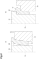
- FIGS. 3(a) and 3(b) When such an operation is not performed well and biting occurs, as shown in FIGS. 3(a) and 3(b) , the workpiece 10 is drawn into the inside of the die 30 in a state where the workpiece 10 is deformed into an unintended shape, which is a risk. Therefore, in the method for manufacturing a bearing ring member according to the embodiment, a first condition formula to be described below is satisfied, and the occurrence of biting is suppressed.
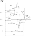
- FIG. 4 is a cross-sectional view taken along a plane parallel to the direction DR at the start of the first step.
- FIG. 5 is a cross-sectional view in a state where an inclination angle ⁇ of the workpiece 10 with respect to the direction DR is equal to the inclination angle ⁇ of the tapered surface 31.
- FIG. 6 is a cross-sectional view in a state where the inclination angle ⁇ of the workpiece 10 between FIGS. 4 and 5 is 30 degrees.
- FIGS. 7(a) and 7(b) are views for describing the position of a contact point B between the workpiece 10 and the first R surface R1. In FIGS. 4 to 6 , hatching indicating cross sections is omitted.
- the present inventors have found that if the following formula (5) (first condition formula) is satisfied when the inclination angle ⁇ of the workpiece 10 is 30 degrees, the occurrence of the biting of the punch 20 into the workpiece 10 can be suppressed.
- the inclination angle ⁇ of the workpiece 10 is 30 degrees in the first step.
- Z d is a distance between a radially inner edge 10ba of an end portion 10b on the second side S2 of the workpiece 10 and the contact point B between the workpiece 10 and the first R surface R1
- Ww is a width of the workpiece 10
- A is a constant of 0.2 or more and 0.6 or less.
- the first condition formula represents that when the inclination angle ⁇ shown in FIG. 6 is 30 degrees, the contact point B is located within the range of a length, which is obtained by multiplying the width Ww of the workpiece 10 by the constant A, from the edge 10ba of the workpiece 10.
- the constant A can be determined, for example, by experiment and/or simulation depending on the shapes, materials, and the like of the workpiece 10, the punch 20, and the die 30. In this example, the constant A is set to 2/5.
- An inclination angle ⁇ of 30 degrees is, for example, a boundary value at which the workpiece 10 starts sliding on the die 30 (second R surface R2). Namely, in this example, until the inclination angle decreases to 30 degrees, no sliding occurs between the workpiece 10 and the second R surface R2, and after the inclination angle becomes smaller than 30 degrees, sliding occurs between the workpiece 10 and the second R surface R2.
- An outer diameter of the workpiece 10 is D bo
- an inner diameter of the workpiece 10 is d bi
- a thickness of the workpiece 10 is t.
- a diameter of the main body portion 21 of the punch 20 is D p
- a radius of the first R surface R1 is r p
- a diameter of the protruding portion 22 of the punch 20 is D pL .
- An inner diameter of the die 30 (distance between the inner peripheral surfaces 32) is D d , a radius of the second R surface R2 is r d , and a diameter of the opening 30a is D h .
- the diameter D pL of the protruding portion 22 and the inner diameter D d of the die 30 are set to be substantially equal.
- the outer diameter D bo of the workpiece 10 is, for example, approximately 10 mm to 60 mm.
- a distance between the edge 10ba of the workpiece 10 and the point Bs is expressed as (D p /2-r p ) - d bi /2.
- a distance between the point Bs and the contact point B is expressed as 2 ⁇ r p ⁇ (90° - ⁇ )/360°.
- (90° - ⁇ ) is an angle at which the workpiece 10 is inclined from the start of the first step until the inclination angle ⁇ reaches 30 degrees
- 2 ⁇ r p ⁇ (90° - ⁇ )/360° is a length of a circular arc with the radius r p corresponding to the angle.
- Ww (D bo - d bi )/2
- the first condition formula can also be expressed as in the following formula (6). Namely, if the following formula (6) is satisfied when the inclination angle ⁇ of the workpiece 10 is 30 degrees, a state where the occurrence of the biting of the punch 20 into the workpiece 10 while the workpiece 10 is caught on the die 30 is suppressed is achieved.
- the constant A is set to 2/5.
- Examples of a second condition include that an end surface of the workpiece 10 can be pushed in by the protruding portion 22 of the punch 20 in the second step.
- the end surface of the workpiece 10 cannot be pushed in by the protruding portion 22 in the second step, as shown in FIGS. 8(a) and 8(b) , the workpiece 10 is crushed by the protruding portion 22, which is a risk. Therefore, in the method for manufacturing a bearing ring member according to the embodiment, a second condition formula described below as Formula (7) is satisfied, and the pushing of the workpiece 10 by the protruding portion 22 is ensured.
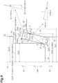
- FIG. 9 is a cross-sectional view in a state where the inclination angle ⁇ of the workpiece 10 is equal to the inclination angle ⁇ of the tapered surface 31.
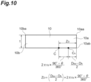
- FIG. 10 is a view for describing the position of a contact point C between the workpiece 10 and the second R surface R2. In FIG. 9 , hatching indicating cross sections is omitted.
- Z D is a distance between a radially outer edge 10ab of the end portion 10a on the first side S1 of the workpiece 10 and the contact point C between the workpiece 10 and the second R surface R2.
- the second condition formula represents that a radially inner edge 10aa of the end portion 10a of the workpiece 10 is located inside an outer edge of the protruding portion 22 in the radial direction at the start of the second step.
- Formula (7) will be further described.
- a first term of (D h /2 - r d cos ⁇ ) on the right side is a distance from the center line CL to the contact point C in the radial direction.
- a second term of ⁇ t/cos ⁇ - (Z D + t ⁇ tan ⁇ )sin ⁇ on the right side is a distance between the edge 10aa of the workpiece 10 and the contact point C in the radial direction. Therefore, the entire right side of Formula (7) represents a distance from the center line CL to the edge 10aa of the workpiece 10 in the radial direction.
- a first term of (D bo - D h )/2 on the right side is a distance in the radial direction between the edge 10ab and the contact point Cs between the workpiece 10 and the second R surface R2 at the start of the first step (refer to FIG. 4 ).
- a second term of 2 ⁇ r d ⁇ (90° - ⁇ )/360° on the right side is a distance between the point Cs and the contact point C.
- the punch 20 has the first R surface R1 formed in a circular arc shape in a cross section parallel to the direction DR
- the die 30 has the second R surface R2 formed in a circular arc shape in a cross section parallel to the direction DR
- the tapered surface 31 that is formed on the second side S2 of the second R surface R2 and that is inclined to approach the center side in the radial direction as the tapered surface 31 extends toward the second side S2.
- the second step of deforming the workpiece 10 using the punch 20 and the die 30 in a state where the first R surface R1 and the tapered surface 31 are in contact with the workpiece 10 is performed. Since the punch 20 and the die 30 have simple shapes or a combination shape thereof in such a manner, whether or not inversion working can be satisfactorily performed can be determined in advance based on geometric calculations. Therefore, according to the method for manufacturing the bearing ring member 1, the design and manufacture of the bearing ring member 1 can be facilitated.
- the design of the punch 20 and the die 30 can be facilitated, and the difference caused by designers can be reduced.
- the number of designers can be increased, and the load can be distributed therebetween.
- work efficiency can be improved, and trial production costs can be reduced.
- the radially inner edge 10aa of the end portion 10a on the first side S1 of the workpiece 10 is located inside the outer edge of the protruding portion 22 of the punch 20 in the radial direction. Accordingly, the workpiece 10 can be reliably pushed in by the protruding portion 22, and the inversion working of the workpiece 10 can be satisfactorily performed.
- the above formula (7) is satisfied at the start of the second step. Accordingly, the workpiece 10 can be reliably pushed in by the protruding portion 22 of the punch 20, and the inversion working of the workpiece 10 can be satisfactorily performed.
- sliding occurs between the workpiece 10 and the second R surface R2 within a range where the inclination angle of the workpiece 10 is decreased to less than 30 degrees in the first step; however, as a first modification example, sliding may not occur between the workpiece 10 and the second R surface R2 throughout the first step.
- the manufacture of the bearing ring member 1 can be facilitated. Whether or not sliding occurs can be determined using a predicted value M of a limiting bending moment of the workpiece 10 to be described below.
- Y is the yield stress of the workpiece 10.
- the yield stress is stress that determines whether or not plastic deformation occurs in the material, and as described above, Ww is the width of the workpiece 10, and t is the thickness of the workpiece 10.
- Ww is the width of the workpiece 10
- t is the thickness of the workpiece 10.
- Formula (4) is described, for example, in Hideaki Kudo's "Fundamental Mechanical Engineering Complete Book 3: Plasticity", published by Morikita Publishing Co., Ltd., First edition, first printing on May 15, 1968, and First edition, 18th printing on March 3, 1995 .
- a bending moment acting on the workpiece 10 can be theoretically calculated by calculating a strain generated in the workpiece 10 from the amount of change in the width of the workpiece 10 in the inversion step, calculating a stress from the strain, calculating an energy from the stress, and calculating a bending moment from the energy.
- FIG. 11 is a graph showing an example of the bending moment acting on the workpiece 10 in the inversion step.
- the horizontal axis in FIG. 11 represents the inclination angle ⁇ (°) of the workpiece 10 with respect to a horizontal direction (direction perpendicular to the axial direction), and the vertical axis represents the bending moment (N ⁇ m) acting on the workpiece 10.
- the bending moment is smaller than the predicted value M of the limiting bending moment within a range where the inclination angle ⁇ is 0 degrees or more and approximately 40 degrees or less. In this case, no sliding occurs between the workpiece 10 and the die 30 within this range.
- the workpiece 10 In order to satisfactorily perform inversion working of the workpiece 10, the workpiece 10 needs to start sliding with respect to the die 30 within a range where the bending moment acting on the workpiece 10 is smaller than the predicted value M of the limiting bending moment.
- the bending moment (maximum bending moment) acting on the workpiece member 10 in the first step is smaller than the predicted value M of the limiting bending moment of the workpiece 10.
- the shapes of the punch 20 and the die 30 are determined such that the bending moment acting on the workpiece 10 in the first step becomes smaller than the predicted value M. Accordingly, in the first step, no sliding occurs between the workpiece 10 and the second R surface R2 of the die 30, and the workpiece can be satisfactorily stood up.
- the workpiece 10 slides on the tapered surface 31 of the die 30, and the workpiece 10 can be reliably drawn into the inside of the die 30.
- FIG. 12 is a view showing a second modification example
- FIG. 12(a) is a cross-sectional view of the punch 20 and the workpiece 10 at the start of the second step
- FIG. 12(b) is a cross-sectional view of the die 30 and the workpiece 10 at the start of the second step.
- a first region 41 of the first R surface R1 which comes into contact with the workpiece 10 in the second step
- the range of the roughened first region 41 is indicated by arrow AR.
- a surface roughness of the first region 41 is larger than a surface roughness of a second region 42 of the first R surface R1 other than the first region 41.
- the surface roughness is an arithmetic average roughness Ra (JIS B 0601 4.2.1).
- the second region 42 and the outer peripheral surface 21a may be ground surfaces subjected to grinding or lapped surfaces subjected to lapping in order to improve sliding.
- the tapered surface 31 is roughened.
- the range of the roughened tapered surface 31 is indicated by arrow AR. Accordingly, a surface roughness of the tapered surface 31 is larger than a surface roughness of the second R surface R2.
- the second R surface R2 and the inner peripheral surface 32 may be ground surfaces subjected to grinding or lapped surfaces subjected to lapping in order to improve sliding.
- inversion working is performed in a state where the surface roughness of the first region 41 is larger than the surface roughness of the second region 42 and the surface roughness of the tapered surface 31 is larger than the surface roughness of the second R surface R2.
- the manufacture of the bearing ring member 1 can be facilitated.
- the punch 20 may be likely to bite into the workpiece 10; however, by performing inversion working in the above-described state, the occurrence of biting can be reliably suppressed, and inversion working can be satisfactorily performed.
- a method for manufacturing the bearing ring member 1 according to the second modification example may include a step of polishing at least one of the punch 20 and the die 30 to obtain the above-described state, before the inversion step.
- the second region 42 of the punch 20 may be polished.
- the second R surface R2 of the die 30 may be polished. Accordingly, it is possible to suppress a situation where the above-described state is no longer satisfied due to wear of at least one of the punch 20 and the die 30, thereby causing a biting defect.
- both the first condition that the surface roughness of the first region 41 is larger than the surface roughness of the second region 42 and the second condition that the surface roughness of the tapered surface 31 is larger than the surface roughness of the second R surface R2 are satisfied; however, inversion working may be performed in a state where only one of the first condition and the second condition is satisfied.
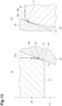
- FIG. 13 is a view showing a third modification example
- FIG. 13(a) is a cross-sectional view of the punch 20 and the workpiece 10 at the start of the second step
- FIG. 13(b) is a cross-sectional view of the die 30 and the workpiece 10 at the start of the second step.
- the punch 20 of the third modification example the second region 42 of the first R surface R1 and a part of the outer peripheral surface 21a, which is continuous with the second region 42, are roughened.
- the roughened range is indicated by arrow AR. Accordingly, a surface roughness of the second region 42 is larger than a surface roughness of the first region 41.
- the first region 41 and portions of the outer peripheral surface 21a other than the above-described part may be ground surfaces subjected to grinding or lapped surfaces subjected to lapping in order to improve sliding.
- a region including the second R surface R2 is roughened.
- the roughened range is indicated by arrow AR.
- a surface roughness of the second R surface R2 is larger than a surface roughness of the tapered surface 31.
- the tapered surface 31 and the inner peripheral surface 32 may be ground surfaces subjected to grinding or lapped surfaces subjected to lapping in order to improve sliding.
- inversion working is performed in a state where the surface roughness of the second region 42 is larger than the surface roughness of the first region 41 and the surface roughness of the second R surface R2 is larger than the surface roughness of the tapered surface 31.
- the manufacture of the bearing ring member 1 can be facilitated.
- a method for manufacturing the bearing ring member 1 according to the third modification example may include a step of polishing at least one of the punch 20 and the die 30 to obtain the above-described state, before the inversion step.
- the first region 41 of the punch 20 may be polished.
- the tapered surface 31 of the die 30 may be polished. Accordingly, it is possible to suppress a situation where the above-described state is no longer satisfied due to wear of at least one of the punch 20 and the die 30, thereby causing a defect.
- both the first condition that the surface roughness of the second region 42 is larger than the surface roughness of the first region 41 and the second condition that the surface roughness of the second R surface R2 is larger than the surface roughness of the tapered surface 31 are satisfied; however, inversion working may be performed in a state where only one of the first condition and the second condition is satisfied.
- the inversion step may further include a third step of applying ironing to the workpiece 10 by sandwiching the workpiece 10 between the outer peripheral surface 21a of the punch 20 and the inner peripheral surface 32 of the die 30 after second step.
- FIG. 14 is a cross-sectional view for describing ironing. In FIG. 14 , the first R surface R1, the second R surface R2, and the like are omitted.
- a gap (gap in the radial direction) between the outer peripheral surface 21a and the inner peripheral surface 32 in the third step may be set to be equal to the thickness of the workpiece 10.
- the thickness of the radially inner portion of the workpiece 10 decreases, and the thickness of the radially outer portion increases.
- the workpiece 10 can be squeezed (made thinner) on a radially outer side on which the thickness increases, and the thickness of the bearing ring member 1 obtained after processing can be matched to the thickness of the workpiece 10.
- the gap between the outer peripheral surface 21a and the inner peripheral surface 32 in the third step may be set to be smaller than the thickness of the workpiece 10.
- the gap may be set to be equal to the thickness of the radially inner portion of the workpiece 10 after normal inversion working.
- the thickness of the bearing ring member 1 obtained after processing can be matched to the thickness of the radially inner portion of the workpiece 10, of which the thickness decreases.
- the manufacture of the bearing ring member 1 can be facilitated.
- the roundness of the obtained bearing ring member 1 can be improved.
- both the first condition formula regarding biting and the second condition formula regarding push-in failure are satisfied; however, only one of the first condition formula and the second condition formula may be satisfied.
- the inversion step of the embodiment as the punch 20 descends and approaches the die 30, the workpiece 10 is sandwiched between the punch 20 and the die 30; however, the punch 20 and the die 30 may move relative to each other, and for example, the workpiece 10 may be sandwiched between the punch 20 and the die 30 by moving both members closer to each other.
- the punch 20 (main body portion 21) is formed in a substantially columnar shape, and the die 30 is formed in a substantially cylindrical shape; however, on the contrary, the punch 20 (main body portion 21) may be formed in a substantially cylindrical shape, and the die 30 may be formed in a substantially columnar shape.
- the first R surface R1 is formed at an inner edge portion of the surface on the second side S2 of the main body portion 21 of the punch 20.
- the second R surface R2 is formed at an outer edge portion of the surface on the first side S1 of the die 30.
- the tapered surface 31 is inclined to approach the center side in the radial direction as the tapered surface 31 extends toward the first side S1 (away from the center in the radial direction as the tapered surface 31 extends toward the second side S2). Namely, the tapered surface 31 may be inclined with respect to the direction DR (predetermined direction).
- bearing ring member 10: workpiece, 10a, 10b: end portion, 10aa, 10ab, 10ba: edge, 20: punch (mold for inversion working), 21: main body portion, 21a: outer peripheral surface, 22: protruding portion, 30: die (mold for inversion working), 30a: opening, 31: tapered surface, 32: inner peripheral surface, 41: first region, 42: second region, DR: direction (predetermined direction), R1: first R surface, R2: second R surface, S1: first side, S2: second side.
Landscapes
- Engineering & Computer Science (AREA)
- Mechanical Engineering (AREA)
- Rolling Contact Bearings (AREA)
Abstract
Description
- One aspect of the present disclosure relates to a method for manufacturing a bearing ring member and a mold for inversion working.
-
Patent Literature 1 describes a method for manufacturing a ring member used to manufacture an inner ring or an outer ring of a bearing. In this manufacturing method, the ring member is formed through a step of performing inversion working in which a workpiece having an annular shape is sandwiched between a punch and a die to change the direction of a cross section by 90 degrees. The punch has a tapered shape, and the die has a composite R shape in which a plurality of R surfaces having different radiuses are combined.Patent Literatures 2 to 5 also describe that a bearing ring member is formed by the same inversion working. -
- Patent Literature 1:
Japanese Unexamined Patent Publication No. 2006-341255 - Patent Literature 2:
Japanese Unexamined Patent Publication No. 2006-090407 - Patent Literature 3:
Japanese Unexamined Patent Publication No. 2006-097809 - Patent Literature 4:
Japanese Unexamined Patent Publication No. 2006-123003 - Patent Literature 5:
Japanese Unexamined Patent Publication No. 2020-022987 - In the manufacturing method described above, it is not easy to design the tapered shape of the punch and the composite R shape of the die such that inversion working can be satisfactorily performed, and since design relies on experience, the difference in design between designers is large, which is a problem. When the difference between designers is large, design work is concentrated on a specific designer, and it is concerned that work efficiency decreases.
- Therefore, an object of one aspect of the present disclosure is to provide a method for manufacturing a bearing ring member, which can facilitate the design and manufacture of the bearing ring member through inversion working, and a mold for inversion working.
- According to one aspect of the present disclosure, there is provided a method for manufacturing a bearing ring member (ring member for bearing) having a cylindrical shape, the method including: an inversion step of deforming a workpiece having an annular shape by sandwiching the workpiece between a punch disposed on a first side in a predetermined direction and a die disposed on a second side opposite to the first side. The punch includes a first R (Radius) surface formed in a circular arc shape in a cross section parallel to the predetermined direction. The die includes a second R (Radius) surface formed in a circular arc shape in a cross section parallel to the predetermined direction, and a tapered surface formed on the second side of the second R surface and inclined to approach a center side in a radial direction as the tapered surface extends toward the second side. The inversion step includes a first step of deforming the workpiece using the punch and the die in a state where the first R surface and the second R surface are in contact with the workpiece, and a second step of deforming the workpiece using the punch and the die in a state where the first R surface and the tapered surface are in contact with the workpiece, after the first step.
- In the method for manufacturing a bearing ring member, the punch includes the first R surface formed in a circular arc shape in a cross section parallel to the predetermined direction, and the die includes the second R surface formed in a circular arc shape in a cross section parallel to the predetermined direction, and the tapered surface formed on the second side of the second R surface and inclined to approach the center side in the radial direction as the tapered surface extends toward the second side. In the inversion step, after the first step of deforming the workpiece using the punch and the die in a state where the first R surface and the second R surface are in contact with the workpiece is performed, the second step of deforming the workpiece using the punch and the die in a state where the first R surface and the tapered surface are in contact with the workpiece is performed. Since the punch and the die have simple shapes or a combination shape thereof in such a manner, whether or not inversion working can be satisfactorily performed can be determined in advance based on geometric calculations. Therefore, according to the method for manufacturing a bearing ring member, the design and manufacture of the bearing ring member can be facilitated.
- In the first step, no sliding may occur between the workpiece and the second R surface, and in the second step, sliding may occur between the workpiece and the tapered surface. In this case, the inversion working of the workpiece can be satisfactorily performed.
- A bending moment acting on the workpiece in the first step may be smaller than a predicted value M of a limiting bending moment of the workpiece calculated using Formula (1). In this case, no sliding occurs between the workpiece and the die in the first step, and the workpiece can be satisfactorily stood up.

- In Formula (1), Ww is a width of the workpiece, t is a thickness of the workpiece, and Y is a yield stress of the workpiece.
- An inclination angle of the tapered surface with respect to the predetermined direction may be smaller than 30 degrees, and Formula (2) may be satisfied at a time that an inclination angle θ of the workpiece with respect to the predetermined direction is 30 degrees. In this case, the occurrence of the biting of the punch into the workpiece can be suppressed, and the inversion working of the workpiece can be satisfactorily performed. Details of biting will be described later.

- In Formula (2), Zd is a distance between a radially inner edge of an end portion on the second side of the workpiece and a contact point between the workpiece and the first R surface, Ww is a width of the workpiece, and A is a constant of 0.2 or more and 0.6 or less.
- The punch may include a main body portion having a columnar shape on which the first R surface is formed. An inclination angle of the tapered surface with respect to the predetermined direction may be smaller than 30 degrees. Formula (3) may be satisfied at a time that an inclination angle θ of the workpiece with respect to the predetermined direction is 30 degrees. In this case, the occurrence of the biting of the punch into the workpiece can be suppressed, and the inversion working of the workpiece can be satisfactorily performed.

- In Formula (3), Dp is a diameter of the main body portion, rp is a radius of the first R surface, dbi is an inner diameter of the workpiece, Dbo is an outer diameter of the workpiece, and A is 2/5.
- The punch may include a main body portion having a columnar shape on which the first R surface is formed, and a protruding portion formed on the first side of the main body portion and protruding outward in a radial direction with respect to the main body portion. At a start of the second step, a radially inner edge of an end portion on the first side of the workpiece may be located inside an outer edge of the protruding portion in the radial direction. In this case, the workpiece can be reliably pushed in by the protruding portion of the punch, and the inversion working of the workpiece can be satisfactorily performed.
- The punch may include a main body portion having a columnar shape on which the first R surface is formed, and a protruding portion formed on the first side of the main body portion and protruding outward in a radial direction with respect to the main body portion. Formula (4) may be satisfied at a start of the second step. In this case, the workpiece can be reliably pushed in by the protruding portion of the punch, and the inversion working of the workpiece can be satisfactorily performed.

- In Formula (4), DpL is a diameter of the protruding portion, Dh is a diameter of an opening of the die defined by the second R surface, rd is a radius of the second R surface, α is an inclination angle of the tapered surface with respect to the predetermined direction, t is a thickness of the workpiece, and ZD is a distance between a radially outer edge of an end portion on the first side of the workpiece and a contact point between the workpiece and the second R surface.
- The inversion step may be performed in a state where a surface roughness of a first region of the first R surface, which comes into contact with the workpiece in the second step, is larger than a surface roughness of a second region of the first R surface other than the first region. In this case, the occurrence of the biting of the punch into the workpiece can be further suppressed, and the inversion working of the workpiece can be satisfactorily performed.
- The inversion step may be performed in a state where a surface roughness of the tapered surface is larger than a surface roughness of the second R surface. In this case, the occurrence of the biting of the punch into the workpiece can be further suppressed, and the inversion working of the workpiece can be satisfactorily performed.
- The inversion step may be performed in a state where a surface roughness of a first region of the first R surface, which comes into contact with the workpiece in the second step, is larger than a surface roughness of a second region of the first R surface other than the first region and a surface roughness of the tapered surface is larger than a surface roughness of the second R surface. In this case, the occurrence of the biting of the punch into the workpiece can be further suppressed, and the inversion working of the workpiece can be satisfactorily performed.
- The inversion step may be performed in a state where a surface roughness of a second region of the first R surface other than a first region which comes into contact with the workpiece in the second step is larger than a surface roughness of the first region of the first R surface. In this case, the workpiece can be more reliably pushed in by the protruding portion of the punch, and the inversion working of the workpiece can be satisfactorily performed.
- The inversion step may be performed in a state where a surface roughness of the second R surface is larger than a surface roughness of the tapered surface. In this case, the workpiece can be more reliably pushed in by the protruding portion of the punch, and the inversion working of the workpiece can be satisfactorily performed.
- The inversion step may be performed in a state where a surface roughness of a second region of the first R surface other than a first region which comes into contact with the workpiece in the second step is larger than a surface roughness of the first region of the first R surface and a surface roughness of the second R surface is larger than a surface roughness of the tapered surface. In this case, the workpiece can be more reliably pushed in by the protruding portion of the punch, and the inversion working of the workpiece can be satisfactorily performed.
- The method for manufacturing a bearing ring member according to one aspect of the present disclosure may further include a step of polishing at least one of the punch and the die to obtain the above-described state, before the inversion step. In this case, it is possible to suppress a situation where the above-described state is no longer satisfied due to wear of at least one of the punch and the die, thereby causing a defect.
- The punch may further includes an outer peripheral surface formed on the first side of the first R surface. The die may further includes an inner peripheral surface formed on the second side of the tapered surface. The inversion step may further include a third step of applying ironing to the workpiece by sandwiching the workpiece between the outer peripheral surface and the inner peripheral surface after the second step. In standard inversion working, the thickness of the radially inner portion of the workpiece decreases, and the thickness of the radially outer portion increases. In this case, by performing ironing between the outer peripheral surface of the punch and the inner peripheral surface of the die, the roundness of the obtained bearing ring member can be improved.
- A gap between the outer peripheral surface and the inner peripheral surface in the third step may be set to be equal to a thickness of the workpiece. In this case, the thickness of the obtained bearing ring member can be matched to the thickness of the workpiece.
- A gap between the outer peripheral surface and the inner peripheral surface in the third step may be set to be smaller than a thickness of the workpiece. In this case, the thickness of the obtained bearing ring member can be matched to the thickness of the radially inner portion of the workpiece, of which the thickness decreases.
- According to one aspect of the present disclosure, there is provided a mold for inversion working for manufacturing a bearing ring member having a cylindrical shape, which is used in inversion working in which a workpiece having an annular shape is deformed by sandwiching the workpiece between a punch disposed on a first side in a predetermined direction and a die disposed on a second side opposite to the first side, the mold including: the punch including a first R surface formed in a circular arc shape in a cross section parallel to the predetermined direction; and the die including a second R surface formed in a circular arc shape in a cross section parallel to the predetermined direction, and a tapered surface formed on the second side of the second R surface and inclined to approach a center side in a radial direction as the tapered surface extends toward the second side.
- In the mold for inversion working, the punch includes the first R surface formed in a circular arc shape in a cross section parallel to the predetermined direction, and the die includes the second R surface formed in a circular arc shape in a cross section parallel to the predetermined direction, and the tapered surface formed on the second side of the second R surface and inclined to approach the center side in the radial direction as the tapered surface extends toward the second side. Accordingly, during inversion working, after a first step of deforming the workpiece using the punch and the die in a state where the first R surface and the second R surface are in contact with the workpiece is performed, a second step of deforming the workpiece using the punch and the die in a state where the first R surface and the tapered surface are in contact with the workpiece can be performed. Since the punch and the die have simple shapes or a combination shape thereof in such a manner, whether or not inversion working can be satisfactorily performed can be determined in advance based on geometric calculations. Therefore, according to the mold for inversion working, the design and manufacture of the bearing ring member can be facilitated.
- According to one aspect of the present disclosure, it is possible to provide the method for manufacturing a bearing ring member, which can facilitate the design and manufacture of the bearing ring member through inversion working, and the mold for inversion working.
-
-
FIG. 1(a) is a cross-sectional view of a bearing ring member, andFIG. 1(b) is a cross-sectional view of a workpiece. -
FIG. 2 is a cross-sectional view of a punch and a die. -
FIGS. 3(a) and 3(b) are views showing an example of a state where the punch bites into the workpiece. -
FIG. 4 is a cross-sectional view at the start of a first step. -
FIG. 5 is a cross-sectional view in a state where an inclination angle of the workpiece is equal to an inclination angle of a tapered surface. -
FIG. 6 is a cross-sectional view in a state where the inclination angle of the workpiece is 30 degrees. -
FIGS. 7(a) and 7(b) are views for describing the position of a contact point between the workpiece and a first R surface. -
FIGS. 8(a) and 8(b) are views showing an example of a state where the workpiece is not pushed in by a protruding portion of the punch. -
FIG. 9 is a cross-sectional view in a state where the inclination angle of the workpiece is equal to the inclination angle of the tapered surface. -
FIG. 10 is a view for describing the position of a contact point between the workpiece and a second R surface. -
FIG. 11 is a graph showing an example of a bending moment acting on the workpiece in an inversion step. -
FIG. 12 is a view showing a second modification example,FIG. 12(a) is a cross-sectional view of the punch and the workpiece at the start of a second step, andFIG. 12(b) is a cross-sectional view of the die and the workpiece at the start of the second step. -
FIG. 13 is a view showing a third modification example,FIG. 13(a) is a cross-sectional view of the punch and the workpiece at the start of the second step, andFIG. 13(b) is a cross-sectional view of the die and the workpiece at the start of the second step. -
FIGS. 14(a), 14(b), and 14(c) are cross-sectional views for describing ironing. - Hereinafter, an embodiment of the present disclosure will be described in detail with reference to the drawings. In the following description, the same reference signs are used for the same or equivalent elements, and duplicate descriptions will be omitted.
- In a method for manufacturing a bearing ring member according to the embodiment, a bearing ring member 1 (
ring member 1 for bearing) shown inFIG. 1(a) is manufactured from aworkpiece 10 shown inFIG. 1(b) . Thebearing ring member 1 can be used, for example, as an inner ring or an outer ring of a bearing. The manufacturedbearing ring member 1 itself may be used as an inner ring or an outer ring, or an inner ring or an outer ring may be manufactured by further processing thebearing ring member 1. Thebearing ring member 1 is formed in a cylindrical shape. The bearing to which thebearing ring member 1 is applied may be any bearing, and for example, may be a needle bearing, a cylindrical roller bearing, a tapered roller bearing, a ball bearing, or the like. Theworkpiece 10 is formed in a disk plate shape.FIGS. 1(a) and 1(b) show cross sections of thebearing ring member 1 and theworkpiece 10, which are parallel to an axial direction. -
FIG. 2 is a cross-sectional view of apunch 20 and a die 30 (mold for inversion working) used in the method for manufacturing a bearing ring member according to the embodiment. This manufacturing method includes an inversion step of deforming theworkpiece 10 by sandwiching theworkpiece 10 between thepunch 20 and thedie 30. The direction of the cross section of theworkpiece 10 is changed by 90 degrees by the inversion step, and thebearing ring member 1 is formed. Before the start of the inversion step, thepunch 20 is disposed on a first side S1 in a direction DR (predetermined direction) with respect to thedie 30, and thedie 30 is disposed on a second side (side opposite to the first side S1) S2 in the direction DR with respect to thepunch 20. Then, by moving (descending) thepunch 20 along the direction DR and bringing thepunch 20 closer to thedie 30, theworkpiece 10 is sandwiched between thepunch 20 and thedie 30, and theworkpiece 10 is subjected to inversion working. Thepunch 20 and the die 30 have a common center line CL, and each of thepunch 20 and thedie 30 has a uniform cross-sectional shape in a radial direction. - As shown in
FIG. 2 , thepunch 20 includes amain body portion 21 and a protrudingportion 22. Themain body portion 21 is formed in a substantially columnar shape having an axis parallel to the direction DR. A first R surface R1 is formed at an outer edge portion of a surface on the second side S2 of themain body portion 21. The first R surface R1 is a curved surface formed by rounding off a corner on the second side S2 of themain body portion 21, and is formed in a circular arc shape in a cross section (FIG. 2 ) parallel to the direction DR. The first R surface R1 extends over the entire circumference of the outer edge portion. A central angle of the first R surface R1 in a cross section parallel to the direction DR is, for example, 90 degrees. Themain body portion 21 has an outerperipheral surface 21a that is continuous with the first side S1 of the first R surface R1. - The protruding
portion 22 is formed on the first side S1 of themain body portion 21, and protrudes outward in the radial direction with respect to themain body portion 21. The protrudingportion 22 is formed, for example, in a columnar shape having a diameter larger than a diameter of themain body portion 21. The protrudingportion 22 has a steppedsurface 22a facing the second side S2. The steppedsurface 22a is continuous with the outerperipheral surface 21a of themain body portion 21. - The
die 30 is formed, for example, in a substantially cylindrical shape having an axis parallel to the direction DR. Thedie 30 has a second R surface R2, atapered surface 31, and an innerperipheral surface 32. The second R surface R2 is formed at an inner edge portion of a surface on the first side S1 of thedie 30. The second R surface R2 is a curved surface formed by rounding off a corner on the first side S1 of the die 30, and is formed in a circular arc shape in a cross section (FIG. 2 ) parallel to the direction DR. The second R surface R2 extends over the entire circumference of the inner edge portion. A central angle of the second R surface R2 in a cross section parallel to the direction DR is, for example, (90 - α) degrees when an inclination angle of the taperedsurface 31 with respect to the direction DR is α. The second R surface R2 defines anopening 30a of the die 30, which opens to the first side S1. - The tapered
surface 31 is continuous with the second side S2 of the second R surface R2, and is inclined to approach a center side in the radial direction as the taperedsurface 31 extends toward the second side S2. The inclination angle α of the taperedsurface 31 with respect to the direction DR is, for example, smaller than 30 degrees. The innerperipheral surface 32 is continuous with the second side S2 of the taperedsurface 31. - As described above, in the inversion step, the
workpiece 10 is sandwiched between thepunch 20 and thedie 30, and theworkpiece 10 is subjected to inversion working. More specifically, the inversion step includes a first step and a second step in order. In the first step, theworkpiece 10 is deformed by thepunch 20 and the die 30 in a state where the first R surface R1 and the second R surface R2 are in contact with the workpiece 10 (for example, as shown inFIG. 6 ). In the second step, theworkpiece 10 is deformed by thepunch 20 and the die 30 in a state where the first R surface R1 and the taperedsurface 31 are in contact with the workpiece 10 (for example, as shown inFIG. 9 ). - In the first step, the
workpiece 10 is deformed to stand up. In the second step, theworkpiece 10 slides on the taperedsurface 31, and theworkpiece 10 is drawn into the inside of the die 30, together with thepunch 20. After the start of the second step, when thepunch 20 further descends, the steppedsurface 22a of the protrudingportion 22 of thepunch 20 comes into contact with anend portion 10a on the first side S1 of theworkpiece 10, and theworkpiece 10 is pushed in by the protrudingportion 22. Thereafter, theworkpiece 10 is disposed between the outerperipheral surface 21a of themain body portion 21 of thepunch 20 and the innerperipheral surface 32 of thedie 30. Thebearing ring member 1 having a cylindrical shape is obtained through the above steps. Hereinafter, conditions for satisfactorily performing inversion working will be described. - Examples of a first condition include that the
punch 20 does not bite into theworkpiece 10 in the first step, and that theworkpiece 10 does not slide off due to being caught on thedie 30. In the first step, thepunch 20 needs to continue pushing a radially inner portion of theworkpiece 10 while a radially outer portion of theworkpiece 10 is caught on thedie 30. When such an operation is not performed well and biting occurs, as shown inFIGS. 3(a) and 3(b) , theworkpiece 10 is drawn into the inside of the die 30 in a state where theworkpiece 10 is deformed into an unintended shape, which is a risk. Therefore, in the method for manufacturing a bearing ring member according to the embodiment, a first condition formula to be described below is satisfied, and the occurrence of biting is suppressed. -
FIG. 4 is a cross-sectional view taken along a plane parallel to the direction DR at the start of the first step.FIG. 5 is a cross-sectional view in a state where an inclination angle θ of theworkpiece 10 with respect to the direction DR is equal to the inclination angle α of the taperedsurface 31.FIG. 6 is a cross-sectional view in a state where the inclination angle θ of theworkpiece 10 betweenFIGS. 4 and5 is 30 degrees.FIGS. 7(a) and 7(b) are views for describing the position of a contact point B between the workpiece 10 and the first R surface R1. InFIGS. 4 to 6 , hatching indicating cross sections is omitted. - The present inventors have found that if the following formula (5) (first condition formula) is satisfied when the inclination angle θ of the
workpiece 10 is 30 degrees, the occurrence of the biting of thepunch 20 into theworkpiece 10 can be suppressed. In the present embodiment, the inclination angle θ of theworkpiece 10 is 30 degrees in the first step.
- In the above formula (5), Zd is a distance between a radially inner edge 10ba of an
end portion 10b on the second side S2 of theworkpiece 10 and the contact point B between the workpiece 10 and the first R surface R1, Ww is a width of theworkpiece 10, and A is a constant of 0.2 or more and 0.6 or less. - The first condition formula represents that when the inclination angle θ shown in
FIG. 6 is 30 degrees, the contact point B is located within the range of a length, which is obtained by multiplying the width Ww of theworkpiece 10 by the constant A, from the edge 10ba of theworkpiece 10. The constant A can be determined, for example, by experiment and/or simulation depending on the shapes, materials, and the like of theworkpiece 10, thepunch 20, and thedie 30. In this example, the constant A is set to 2/5. An inclination angle θ of 30 degrees is, for example, a boundary value at which theworkpiece 10 starts sliding on the die 30 (second R surface R2). Namely, in this example, until the inclination angle decreases to 30 degrees, no sliding occurs between the workpiece 10 and the second R surface R2, and after the inclination angle becomes smaller than 30 degrees, sliding occurs between the workpiece 10 and the second R surface R2. - Formula (5) will be further described. Contact points between the workpiece 10 and both the first R surface R1 and the second R surface R2 at the start of the first step shown in
FIG. 4 are Bs and Cs, respectively. At the start of the first step, the inclination angle θ of theworkpiece 10 is 90 degrees, and theworkpiece 10 is sandwiched between thepunch 20 and the die 30 in a state where main surfaces of theworkpiece 10 are perpendicular to the direction DR. - An outer diameter of the
workpiece 10 is Dbo, an inner diameter of theworkpiece 10 is dbi, and a thickness of theworkpiece 10 is t. The width Ww of theworkpiece 10 is expressed as Ww = (Dbo - dbi)/2 using the outer diameter Dbo and the inner diameter dbi. A diameter of themain body portion 21 of thepunch 20 is Dp, a radius of the first R surface R1 is rp, and a diameter of the protrudingportion 22 of thepunch 20 is DpL. An inner diameter of the die 30 (distance between the inner peripheral surfaces 32) is Dd, a radius of the second R surface R2 is rd, and a diameter of theopening 30a is Dh. In this example, the diameter DpL of the protrudingportion 22 and the inner diameter Dd of the die 30 are set to be substantially equal. The outer diameter Dbo of theworkpiece 10 is, for example, approximately 10 mm to 60 mm. - As shown in
FIG. 4 , a distance between the edge 10ba of theworkpiece 10 and the point Bs is expressed as (Dp/2-rp) - dbi/2. Meanwhile, as shown inFIGS. 6 and7 , a distance between the point Bs and the contact point B is expressed as 2πrp × (90° - θ)/360°. (90° - θ) is an angle at which theworkpiece 10 is inclined from the start of the first step until the inclination angle θ reaches 30 degrees, and 2πrp × (90° - θ)/360° is a length of a circular arc with the radius rp corresponding to the angle. Therefore, the distance Zd between the edge 10ba and the contact point B is expressed as Zd = {(Dp/2 - rp) - dbi/2} + 2πrp × (90° - θ)/360°. As described above, since the width Ww of theworkpiece 10 is expressed as Ww = (Dbo - dbi)/2, the first condition formula can also be expressed as in the following formula (6). Namely, if the following formula (6) is satisfied when the inclination angle θ of theworkpiece 10 is 30 degrees, a state where the occurrence of the biting of thepunch 20 into theworkpiece 10 while theworkpiece 10 is caught on thedie 30 is suppressed is achieved. As described above, in this example, the constant A is set to 2/5.
- Examples of a second condition include that an end surface of the
workpiece 10 can be pushed in by the protrudingportion 22 of thepunch 20 in the second step. When the end surface of theworkpiece 10 cannot be pushed in by the protrudingportion 22 in the second step, as shown inFIGS. 8(a) and 8(b) , theworkpiece 10 is crushed by the protrudingportion 22, which is a risk. Therefore, in the method for manufacturing a bearing ring member according to the embodiment, a second condition formula described below as Formula (7) is satisfied, and the pushing of theworkpiece 10 by the protrudingportion 22 is ensured. -
FIG. 9 is a cross-sectional view in a state where the inclination angle θ of theworkpiece 10 is equal to the inclination angle α of the taperedsurface 31.FIG. 10 is a view for describing the position of a contact point C between the workpiece 10 and the second R surface R2. InFIG. 9 , hatching indicating cross sections is omitted. - The present inventors have found that if the following formula (7) (second condition formula) is satisfied at the start of the second step (the state shown in
FIG. 9 ), theworkpiece 10 can be reliably pushed in by the protrudingportion 22.
- In the above formula (7), ZD is a distance between a radially outer edge 10ab of the
end portion 10a on the first side S1 of theworkpiece 10 and the contact point C between the workpiece 10 and the second R surface R2. The second condition formula represents that a radially inner edge 10aa of theend portion 10a of theworkpiece 10 is located inside an outer edge of the protrudingportion 22 in the radial direction at the start of the second step. - Formula (7) will be further described. As shown in
FIG. 9 , a first term of (Dh/2 - rdcosα) on the right side is a distance from the center line CL to the contact point C in the radial direction. A second term of {t/cosα - (ZD + t × tanα)sinα} on the right side is a distance between the edge 10aa of theworkpiece 10 and the contact point C in the radial direction. Therefore, the entire right side of Formula (7) represents a distance from the center line CL to the edge 10aa of theworkpiece 10 in the radial direction. - As shown in
FIGS. 9 and10 , the distance ZD between the edge 10ab of theworkpiece 10 and the contact point C is expressed as ZD = (Dbo - Dh)/2 + 2πrd × (90° - α)/360°. A first term of (Dbo - Dh)/2 on the right side is a distance in the radial direction between the edge 10ab and the contact point Cs between the workpiece 10 and the second R surface R2 at the start of the first step (refer toFIG. 4 ). A second term of 2πrd × (90° - α)/360° on the right side is a distance between the point Cs and the contact point C. (90° - α) is an angle at which theworkpiece 10 is inclined from the start of the first step until the inclination angle θ reaches the angle α, and 2πrd × (90° - α)/360° is a length of a circular arc with the radius rd corresponding to the angle. In addition, as shown inFIG. 5 , regarding the diameter Dh, for example, a relationship of Dh/2 = Dd/2 + 3/4 × WWsinα + rdcosα is established. In this case, the diameter Dh is expressed as Dh = Dd + 3/2 × WWsinα + 2rdcosα. - In the method for manufacturing the
bearing ring member 1 according to the embodiment, thepunch 20 has the first R surface R1 formed in a circular arc shape in a cross section parallel to the direction DR, and thedie 30 has the second R surface R2 formed in a circular arc shape in a cross section parallel to the direction DR, and the taperedsurface 31 that is formed on the second side S2 of the second R surface R2 and that is inclined to approach the center side in the radial direction as the taperedsurface 31 extends toward the second side S2. In the inversion step, after the first step of deforming theworkpiece 10 using thepunch 20 and the die 30 in a state where the first R surface R1 and the second R surface R2 are in contact with theworkpiece 10 is performed, the second step of deforming theworkpiece 10 using thepunch 20 and the die 30 in a state where the first R surface R1 and the taperedsurface 31 are in contact with theworkpiece 10 is performed. Since thepunch 20 and the die 30 have simple shapes or a combination shape thereof in such a manner, whether or not inversion working can be satisfactorily performed can be determined in advance based on geometric calculations. Therefore, according to the method for manufacturing thebearing ring member 1, the design and manufacture of thebearing ring member 1 can be facilitated. In addition, the design of thepunch 20 and the die 30 can be facilitated, and the difference caused by designers can be reduced. In addition, the number of designers can be increased, and the load can be distributed therebetween. In addition, work efficiency can be improved, and trial production costs can be reduced. - The above formulas (5) and (6) are satisfied at the time that the inclination angle θ of the
workpiece 10 with respect to the direction DR is 30 degrees. Accordingly, the occurrence of the biting of thepunch 20 into theworkpiece 10 while theworkpiece 10 is caught on the die 30 can be suppressed, and the inversion working of theworkpiece 10 can be satisfactorily performed. - At the start of the second step, the radially inner edge 10aa of the
end portion 10a on the first side S1 of theworkpiece 10 is located inside the outer edge of the protrudingportion 22 of thepunch 20 in the radial direction. Accordingly, theworkpiece 10 can be reliably pushed in by the protrudingportion 22, and the inversion working of theworkpiece 10 can be satisfactorily performed. - The above formula (7) is satisfied at the start of the second step. Accordingly, the
workpiece 10 can be reliably pushed in by the protrudingportion 22 of thepunch 20, and the inversion working of theworkpiece 10 can be satisfactorily performed. - In the embodiment, sliding occurs between the workpiece 10 and the second R surface R2 within a range where the inclination angle of the
workpiece 10 is decreased to less than 30 degrees in the first step; however, as a first modification example, sliding may not occur between the workpiece 10 and the second R surface R2 throughout the first step. In the first modification example as well, similarly to the embodiment, the manufacture of thebearing ring member 1 can be facilitated. Whether or not sliding occurs can be determined using a predicted value M of a limiting bending moment of theworkpiece 10 to be described below. - When a bending moment (maximum bending moment) acting on the
workpiece 10 is smaller than the predicted value M of the limiting bending moment of theworkpiece 10 calculated by the following formula (8), no sliding occurs between the workpiece 10 and thedie 30, and theworkpiece 10 stands up without sliding on the die 30 in the first step.
- In the above formula (8), Y is the yield stress of the
workpiece 10. The yield stress is stress that determines whether or not plastic deformation occurs in the material, and as described above, Ww is the width of theworkpiece 10, and t is the thickness of theworkpiece 10. When stress larger than the yield stress acts, the material undergoes plastic deformation, and stress smaller than the yield stress acts, the material undergoes elastic deformation. Formula (4) is described, for example, in Hideaki Kudo's "Fundamental Mechanical Engineering Complete Book 3: Plasticity", published by Morikita Publishing Co., Ltd., First edition, first printing on May 15, 1968, and First edition, 18th printing on March 3, 1995. For example, a bending moment acting on theworkpiece 10 can be theoretically calculated by calculating a strain generated in theworkpiece 10 from the amount of change in the width of theworkpiece 10 in the inversion step, calculating a stress from the strain, calculating an energy from the stress, and calculating a bending moment from the energy. -
FIG. 11 is a graph showing an example of the bending moment acting on theworkpiece 10 in the inversion step. The horizontal axis inFIG. 11 represents the inclination angle θ (°) of theworkpiece 10 with respect to a horizontal direction (direction perpendicular to the axial direction), and the vertical axis represents the bending moment (N·m) acting on theworkpiece 10. As shown inFIG. 11 , in this example, the bending moment is smaller than the predicted value M of the limiting bending moment within a range where the inclination angle θ is 0 degrees or more and approximately 40 degrees or less. In this case, no sliding occurs between the workpiece 10 and thedie 30 within this range. - In order to satisfactorily perform inversion working of the
workpiece 10, theworkpiece 10 needs to start sliding with respect to the die 30 within a range where the bending moment acting on theworkpiece 10 is smaller than the predicted value M of the limiting bending moment. In the first modification example, the bending moment (maximum bending moment) acting on theworkpiece member 10 in the first step is smaller than the predicted value M of the limiting bending moment of theworkpiece 10. In other words, the shapes of thepunch 20 and the die 30 are determined such that the bending moment acting on theworkpiece 10 in the first step becomes smaller than the predicted value M. Accordingly, in the first step, no sliding occurs between the workpiece 10 and the second R surface R2 of the die 30, and the workpiece can be satisfactorily stood up. In the second step, theworkpiece 10 slides on the taperedsurface 31 of the die 30, and theworkpiece 10 can be reliably drawn into the inside of thedie 30. -
FIG. 12 is a view showing a second modification example,FIG. 12(a) is a cross-sectional view of thepunch 20 and theworkpiece 10 at the start of the second step, andFIG. 12(b) is a cross-sectional view of thedie 30 and theworkpiece 10 at the start of the second step. In thepunch 20 of the second modification example, afirst region 41 of the first R surface R1, which comes into contact with theworkpiece 10 in the second step, is roughened. InFIG. 12(a) , the range of the roughenedfirst region 41 is indicated by arrow AR. Accordingly, a surface roughness of thefirst region 41 is larger than a surface roughness of asecond region 42 of the first R surface R1 other than thefirst region 41. The surface roughness is an arithmetic average roughness Ra (JIS B 0601 4.2.1). Thesecond region 42 and the outerperipheral surface 21a may be ground surfaces subjected to grinding or lapped surfaces subjected to lapping in order to improve sliding. - In addition, in the
die 30 of the second modification example, the taperedsurface 31 is roughened. InFIG. 12(b) , the range of the roughened taperedsurface 31 is indicated by arrow AR. Accordingly, a surface roughness of the taperedsurface 31 is larger than a surface roughness of the second R surface R2. The second R surface R2 and the innerperipheral surface 32 may be ground surfaces subjected to grinding or lapped surfaces subjected to lapping in order to improve sliding. - In the second modification example, inversion working is performed in a state where the surface roughness of the
first region 41 is larger than the surface roughness of thesecond region 42 and the surface roughness of the taperedsurface 31 is larger than the surface roughness of the second R surface R2. In the second modification example as well, similarly to the embodiment, the manufacture of thebearing ring member 1 can be facilitated. In addition, depending on the size of theworkpiece 10, thepunch 20 may be likely to bite into theworkpiece 10; however, by performing inversion working in the above-described state, the occurrence of biting can be reliably suppressed, and inversion working can be satisfactorily performed. - A method for manufacturing the
bearing ring member 1 according to the second modification example may include a step of polishing at least one of thepunch 20 and the die 30 to obtain the above-described state, before the inversion step. For example, when thepunch 20 is worn due to inversion working being repeatedly performed, and biting is about to occur, thesecond region 42 of thepunch 20 may be polished. Alternatively, when thedie 30 is worn and biting is about to occur, the second R surface R2 of the die 30 may be polished. Accordingly, it is possible to suppress a situation where the above-described state is no longer satisfied due to wear of at least one of thepunch 20 and thedie 30, thereby causing a biting defect. In the second modification example, both the first condition that the surface roughness of thefirst region 41 is larger than the surface roughness of thesecond region 42 and the second condition that the surface roughness of the taperedsurface 31 is larger than the surface roughness of the second R surface R2 are satisfied; however, inversion working may be performed in a state where only one of the first condition and the second condition is satisfied. -
FIG. 13 is a view showing a third modification example,FIG. 13(a) is a cross-sectional view of thepunch 20 and theworkpiece 10 at the start of the second step, andFIG. 13(b) is a cross-sectional view of thedie 30 and theworkpiece 10 at the start of the second step. In thepunch 20 of the third modification example, thesecond region 42 of the first R surface R1 and a part of the outerperipheral surface 21a, which is continuous with thesecond region 42, are roughened. InFIG. 13(a) , the roughened range is indicated by arrow AR. Accordingly, a surface roughness of thesecond region 42 is larger than a surface roughness of thefirst region 41. In the third modification example, thefirst region 41 and portions of the outerperipheral surface 21a other than the above-described part may be ground surfaces subjected to grinding or lapped surfaces subjected to lapping in order to improve sliding. - In addition, in the
die 30 of the third modification example, a region including the second R surface R2 is roughened. InFIG. 13(b) , the roughened range is indicated by arrow AR. Accordingly, a surface roughness of the second R surface R2 is larger than a surface roughness of the taperedsurface 31. In the third modification example, the taperedsurface 31 and the innerperipheral surface 32 may be ground surfaces subjected to grinding or lapped surfaces subjected to lapping in order to improve sliding. - In the third modification example, inversion working is performed in a state where the surface roughness of the
second region 42 is larger than the surface roughness of thefirst region 41 and the surface roughness of the second R surface R2 is larger than the surface roughness of the taperedsurface 31. In the third modification example as well, similarly to the embodiment, the manufacture of thebearing ring member 1 can be facilitated. In addition, depending on the size of theworkpiece 10, it may be difficult to push theworkpiece 10 in by using the protrudingportion 22 of thepunch 20; however, by performing inversion working in the above-described state, the occurrence of a push-in failure can be reliably suppressed, and inversion working can be satisfactorily performed. - A method for manufacturing the
bearing ring member 1 according to the third modification example may include a step of polishing at least one of thepunch 20 and the die 30 to obtain the above-described state, before the inversion step. For example, when thepunch 20 is worn due to inversion working being repeatedly performed, and a push-in failure is about to occur, thefirst region 41 of thepunch 20 may be polished. Alternatively, when thedie 30 is worn and a push-in failure is about to occur, the taperedsurface 31 of the die 30 may be polished. Accordingly, it is possible to suppress a situation where the above-described state is no longer satisfied due to wear of at least one of thepunch 20 and thedie 30, thereby causing a defect. In the third modification example, both the first condition that the surface roughness of thesecond region 42 is larger than the surface roughness of thefirst region 41 and the second condition that the surface roughness of the second R surface R2 is larger than the surface roughness of the taperedsurface 31 are satisfied; however, inversion working may be performed in a state where only one of the first condition and the second condition is satisfied. - As a fourth modification example, the inversion step may further include a third step of applying ironing to the
workpiece 10 by sandwiching theworkpiece 10 between the outerperipheral surface 21a of thepunch 20 and the innerperipheral surface 32 of the die 30 after second step.FIG. 14 is a cross-sectional view for describing ironing. InFIG. 14 , the first R surface R1, the second R surface R2, and the like are omitted. - As one example, a gap (gap in the radial direction) between the outer
peripheral surface 21a and the innerperipheral surface 32 in the third step may be set to be equal to the thickness of theworkpiece 10. In normal inversion working, the thickness of the radially inner portion of theworkpiece 10 decreases, and the thickness of the radially outer portion increases. By setting the gap between the outerperipheral surface 21a and the innerperipheral surface 32 to be equal to the thickness of theworkpiece 10 as in this example, theworkpiece 10 can be squeezed (made thinner) on a radially outer side on which the thickness increases, and the thickness of thebearing ring member 1 obtained after processing can be matched to the thickness of theworkpiece 10. - As another example, the gap between the outer
peripheral surface 21a and the innerperipheral surface 32 in the third step may be set to be smaller than the thickness of theworkpiece 10. For example, the gap may be set to be equal to the thickness of the radially inner portion of theworkpiece 10 after normal inversion working. In this case, the thickness of thebearing ring member 1 obtained after processing can be matched to the thickness of the radially inner portion of theworkpiece 10, of which the thickness decreases. - In the fourth modification example as well, similarly to the embodiment, the manufacture of the
bearing ring member 1 can be facilitated. In addition, by performing ironing between the outerperipheral surface 21a of thepunch 20 and the innerperipheral surface 32 of the die 30, the roundness of the obtainedbearing ring member 1 can be improved. - The present disclosure is not limited to the embodiment and the modification examples. In the embodiment, both the first condition formula regarding biting and the second condition formula regarding push-in failure are satisfied; however, only one of the first condition formula and the second condition formula may be satisfied. In the inversion step of the embodiment, as the
punch 20 descends and approaches thedie 30, theworkpiece 10 is sandwiched between thepunch 20 and thedie 30; however, thepunch 20 and the die 30 may move relative to each other, and for example, theworkpiece 10 may be sandwiched between thepunch 20 and the die 30 by moving both members closer to each other. - In the embodiment, the punch 20 (main body portion 21) is formed in a substantially columnar shape, and the
die 30 is formed in a substantially cylindrical shape; however, on the contrary, the punch 20 (main body portion 21) may be formed in a substantially cylindrical shape, and the die 30 may be formed in a substantially columnar shape. In this case, the first R surface R1 is formed at an inner edge portion of the surface on the second side S2 of themain body portion 21 of thepunch 20. In thedie 30, the second R surface R2 is formed at an outer edge portion of the surface on the first side S1 of thedie 30. The taperedsurface 31 is inclined to approach the center side in the radial direction as the taperedsurface 31 extends toward the first side S1 (away from the center in the radial direction as the taperedsurface 31 extends toward the second side S2). Namely, the taperedsurface 31 may be inclined with respect to the direction DR (predetermined direction). - 1: bearing ring member, 10: workpiece, 10a, 10b: end portion, 10aa, 10ab, 10ba: edge, 20: punch (mold for inversion working), 21: main body portion, 21a: outer peripheral surface, 22: protruding portion, 30: die (mold for inversion working), 30a: opening, 31: tapered surface, 32: inner peripheral surface, 41: first region, 42: second region, DR: direction (predetermined direction), R1: first R surface, R2: second R surface, S1: first side, S2: second side.
Claims (19)
- A method for manufacturing a bearing ring member having a cylindrical shape, the method comprising:an inversion step of deforming a workpiece having an annular shape by sandwiching the workpiece between a punch disposed on a first side in a predetermined direction and a die disposed on a second side opposite to the first side,wherein the punch includes a first R surface formed in a circular arc shape in a cross section parallel to the predetermined direction,the die includes a second R surface formed in a circular arc shape in a cross section parallel to the predetermined direction, and a tapered surface formed on the second side of the second R surface and inclined with respect to the predetermined direction, andthe inversion step includes a first step of deforming the workpiece using the punch and the die in a state where the first R surface and the second R surface are in contact with the workpiece, and a second step of deforming the workpiece using the punch and the die in a state where the first R surface and the tapered surface are in contact with the workpiece, after the first step.
- The method for manufacturing a bearing ring member according to claim 1,wherein in the first step, no sliding occurs between the workpiece and the second R surface, andin the second step, sliding occurs between the workpiece and the tapered surface.
- The method for manufacturing a bearing ring member according to claim 1 or 2,wherein a bending moment acting on the workpiece in the first step is smaller than a predicted value M of a limiting bending moment of the workpiece calculated using Formula (1),
 in Formula (1), Ww is a width of the workpiece, t is a thickness of the workpiece, and Y is a yield stress of the workpiece.
 - The method for manufacturing a bearing ring member according to any one of claims 1 to 3,wherein an inclination angle of the tapered surface with respect to the predetermined direction is smaller than 30 degrees, andFormula (2) is satisfied at a time that an inclination angle θ of the workpiece with respect to the predetermined direction is 30 degrees,
 in Formula (2), Zd is a distance between a radially inner edge of an end portion on the second side of the workpiece and a contact point between the workpiece and the first R surface, Ww is a width of the workpiece, and A is a constant of 0.2 or more and 0.6 or less.
 - The method for manufacturing a bearing ring member according to any one of claims 1 to 4,wherein the punch includes a main body portion having a columnar shape on which the first R surface is formed,an inclination angle of the tapered surface with respect to the predetermined direction is smaller than 30 degrees, andFormula (3) is satisfied at a time that an inclination angle θ of the workpiece with respect to the predetermined direction is 30 degrees,
 in Formula (3), Dp is a diameter of the main body portion, rp is a radius of first R surface, dbi is an inner diameter of the workpiece, Dbo is an outer diameter of the workpiece, and A is 2/5.
 - The method for manufacturing a bearing ring member according to any one of claims 1 to 5,wherein the punch includes a main body portion having a columnar shape on which the first R surface is formed, and a protruding portion formed on the first side of the main body portion and protruding outward in a radial direction with respect to the main body portion, andat a start of the second step, a radially inner edge of an end portion on the first side of the workpiece is located inside an outer edge of the protruding portion in the radial direction.
- The method for manufacturing a bearing ring member according to any one of claims 1 to 6,wherein the punch includes a main body portion having a columnar shape on which the first R surface is formed, and a protruding portion formed on the first side of the main body portion and protruding outward in a radial direction with respect to the main body portion, andFormula (4) is satisfied at a start of the second step,
 in Formula (4), DpL is a diameter of the protruding portion, Dh is a diameter of an opening of the die defined by the second R surface, rd is a radius of the second R surface, α is an inclination angle of the tapered surface with respect to the predetermined direction, t is a thickness of the workpiece, and ZD is a distance between a radially outer edge of an end portion on the first side of the workpiece and a contact point between the workpiece and the second R surface.
 - The method for manufacturing a bearing ring member according to any one of claims 1 to 7,
wherein the inversion step is performed in a state where a surface roughness of a first region of the first R surface, which comes into contact with the workpiece in the second step, is larger than a surface roughness of a second region of the first R surface other than the first region. - The method for manufacturing a bearing ring member according to any one of claims 1 to 8,
wherein the inversion step is performed in a state where a surface roughness of the tapered surface is larger than a surface roughness of the second R surface. - The method for manufacturing a bearing ring member according to any one of claims 1 to 7,
wherein the inversion step is performed in a state where a surface roughness of a first region of the first R surface, which comes into contact with the workpiece in the second step, is larger than a surface roughness of a second region of the first R surface other than the first region and a surface roughness of the tapered surface is larger than a surface roughness of the second R surface. - The method for manufacturing a bearing ring member according to any one of claims 1 to 7,
wherein the inversion step is performed in a state where a surface roughness of a second region of the first R surface other than a first region which comes into contact with the workpiece in the second step is larger than a surface roughness of the first region of the first R surface. - The method for manufacturing a bearing ring member according to any one of claims 1 to 7 and 11,
wherein the inversion step is performed in a state where a surface roughness of the second R surface is larger than a surface roughness of the tapered surface. - The method for manufacturing a bearing ring member according to any one of claims 1 to 7,
wherein the inversion step is performed in a state where a surface roughness of a second region of the first R surface other than a first region which comes into contact with the workpiece in the second step is larger than a surface roughness of the first region of the first R surface and a surface roughness of the second R surface is larger than a surface roughness of the tapered surface. - The method for manufacturing a bearing ring member according to any one of claims 8 to 13, further comprising:
a step of polishing at least one of the punch and the die to obtain the above-described state, before the inversion step. - The method for manufacturing a bearing ring member according to any one of claims 1 to 14,wherein the punch further includes an outer peripheral surface formed on the first side of the first R surface,the die further includes an inner peripheral surface formed on the second side of the tapered surface, andthe inversion step further includes a third step of applying ironing to the workpiece by sandwiching the workpiece between the outer peripheral surface and the inner peripheral surface after the second step.
- The method for manufacturing a bearing ring member according to claim 15,
wherein a gap between the outer peripheral surface and the inner peripheral surface in the third step is set to be equal to a thickness of the workpiece. - The method for manufacturing a bearing ring member according to claim 15,
wherein a gap between the outer peripheral surface and the inner peripheral surface in the third step is set to be smaller than a thickness of the workpiece. - The method for manufacturing a bearing ring member according to any one of claims 1 to 17,
wherein the tapered surface is inclined to approach a center side in a radial direction as the tapered surface extends toward the second side. - A mold for inversion working for manufacturing a bearing ring member having a cylindrical shape, which is used in inversion working in which a workpiece having an annular shape is deformed by sandwiching the workpiece between a punch disposed on a first side in a predetermined direction and a die disposed on a second side opposite to the first side, the mold comprising:the punch including a first R surface formed in a circular arc shape in a cross section parallel to the predetermined direction; andthe die including a second R surface formed in a circular arc shape in a cross section parallel to the predetermined direction, and a tapered surface formed on the second side of the second R surface and inclined with respect to the predetermined direction.
Applications Claiming Priority (2)
| Application Number | Priority Date | Filing Date | Title |
|---|---|---|---|
| JP2021189961 | 2021-11-24 | ||
| PCT/JP2022/042608 WO2023095701A1 (en) | 2021-11-24 | 2022-11-16 | Method for manufacturing ring member for bearing, and mold for inversion working |
Publications (2)
| Publication Number | Publication Date |
|---|---|
| EP4420807A1 true EP4420807A1 (en) | 2024-08-28 |
| EP4420807A4 EP4420807A4 (en) | 2025-10-08 |
Family
ID=86539666
Family Applications (1)
| Application Number | Title | Priority Date | Filing Date |
|---|---|---|---|
| EP22898485.2A Pending EP4420807A4 (en) | 2021-11-24 | 2022-11-16 | Method for producing a ring element for a bearing and mold for reverse machining |
Country Status (5)
| Country | Link |
|---|---|
| US (1) | US12409487B2 (en) |
| EP (1) | EP4420807A4 (en) |
| JP (1) | JP7726293B2 (en) |
| CN (1) | CN118317842A (en) |
| WO (1) | WO2023095701A1 (en) |
Family Cites Families (11)
| Publication number | Priority date | Publication date | Assignee | Title |
|---|---|---|---|---|
| US2267229A (en) * | 1939-05-12 | 1941-12-23 | Bower Roller Bearing Co | Method of forming roller bearing cups |
| EP1792672A4 (en) | 2004-09-22 | 2008-10-29 | Nsk Ltd | Raceway ring for radial ball bearing, method of producing the raceway ring, and method and device for producing high precision ring |
| JP2006341255A (en) | 2005-06-07 | 2006-12-21 | Nsk Ltd | Manufacturing method of high precision ring |
| JP4572644B2 (en) | 2004-09-30 | 2010-11-04 | 日本精工株式会社 | Manufacturing method of high precision ring |
| JP2006123003A (en) | 2004-10-01 | 2006-05-18 | Nsk Ltd | High precision ring manufacturing method and manufacturing apparatus |
| JP2006090407A (en) | 2004-09-22 | 2006-04-06 | Nsk Ltd | Radial ball bearing raceway and method for manufacturing the same |
| DE102007027216A1 (en) * | 2007-06-13 | 2008-12-18 | Schaeffler Kg | Method for chipless production of a rolling bearing |
| JP2009226422A (en) * | 2008-03-21 | 2009-10-08 | Nisshin Steel Co Ltd | Method of working tubular member made of metal, with high accuracy |
| JP2010188355A (en) | 2009-02-16 | 2010-09-02 | Okita Tekkosho:Kk | Method for forging short cylindrical part with flange or the like |
| JP7155731B2 (en) | 2018-08-08 | 2022-10-19 | 日本精工株式会社 | Method for manufacturing flanged cylindrical member, method for manufacturing rolling bearing with flange, method for manufacturing rotating machine, and method for manufacturing vehicle |
| JP2020122569A (en) | 2019-09-11 | 2020-08-13 | 日鉄日新製鋼株式会社 | Cylindrical rotating parts |
-
2022
- 2022-11-16 JP JP2023563647A patent/JP7726293B2/en active Active
- 2022-11-16 EP EP22898485.2A patent/EP4420807A4/en active Pending
- 2022-11-16 US US18/712,251 patent/US12409487B2/en active Active
- 2022-11-16 CN CN202280077569.0A patent/CN118317842A/en active Pending
- 2022-11-16 WO PCT/JP2022/042608 patent/WO2023095701A1/en not_active Ceased
Also Published As
| Publication number | Publication date |
|---|---|
| CN118317842A (en) | 2024-07-09 |
| US12409487B2 (en) | 2025-09-09 |
| WO2023095701A1 (en) | 2023-06-01 |
| US20250010355A1 (en) | 2025-01-09 |
| EP4420807A4 (en) | 2025-10-08 |
| JPWO2023095701A1 (en) | 2023-06-01 |
| JP7726293B2 (en) | 2025-08-20 |
Similar Documents
| Publication | Publication Date | Title |
|---|---|---|
| EP2315958B1 (en) | Method of manufacturing a split bearing ring | |
| JPS62184220A (en) | Roller bearing | |
| US20110116734A1 (en) | Punched retainer, self-aligning roller bearing, and method of manufacturing punched retainer | |
| US20100101091A1 (en) | Manufacturing method for bearing outer ring | |
| EP3385552A1 (en) | Self-aligning roller bearing | |
| JPH05318013A (en) | Manufacture of bearing race | |
| EP2840268B1 (en) | Method for manufacturing a ribbon cage | |
| US11143235B2 (en) | Tapered roller bearing | |
| JP7155731B2 (en) | Method for manufacturing flanged cylindrical member, method for manufacturing rolling bearing with flange, method for manufacturing rotating machine, and method for manufacturing vehicle | |
| US10105799B2 (en) | Hub unit manufacturing apparatus | |
| US12409487B2 (en) | Method for manufacturing ring member for bearing, and mold for inversion working | |
| US20170114829A1 (en) | Bearing device and method for manufacturing bearing device | |
| JP2009041757A (en) | Method for manufacturing metal cage | |
| US6772615B2 (en) | Method of manufacturing hub unit for supporting wheel and die for manufacturing the same | |
| JP2006123003A (en) | High precision ring manufacturing method and manufacturing apparatus | |
| JP2007170418A (en) | Tapered roller bearing | |
| US9599160B2 (en) | Tapered roller bearing | |
| JP7004092B2 (en) | Caulking assembly and its manufacturing method, hub unit bearing and its manufacturing method, and automobile and its manufacturing method. | |
| US20250010356A1 (en) | Method for manufacturing bearing ring member | |
| JP2010025230A (en) | Pressed cage, self-aligning roller bearing, and manufacturing method for pressed cage | |
| CN217682864U (en) | Prevent peristaltic casing of bearing inner race | |
| JP2015206392A (en) | Roller bearing with cage cage | |
| JPWO2023095701A5 (en) | ||
| JPH0639477A (en) | Inner ring molding equipment for constant velocity ball joints | |
| JP2008309211A (en) | Roller bearing cage and its manufacturing method |
Legal Events
| Date | Code | Title | Description |
|---|---|---|---|
| STAA | Information on the status of an ep patent application or granted ep patent |
Free format text: STATUS: THE INTERNATIONAL PUBLICATION HAS BEEN MADE |
|
| PUAI | Public reference made under article 153(3) epc to a published international application that has entered the european phase |
Free format text: ORIGINAL CODE: 0009012 |
|
| STAA | Information on the status of an ep patent application or granted ep patent |
Free format text: STATUS: REQUEST FOR EXAMINATION WAS MADE |
|
| 17P | Request for examination filed |
Effective date: 20240523 |
|
| AK | Designated contracting states |
Kind code of ref document: A1 Designated state(s): AL AT BE BG CH CY CZ DE DK EE ES FI FR GB GR HR HU IE IS IT LI LT LU LV MC ME MK MT NL NO PL PT RO RS SE SI SK SM TR |
|
| DAV | Request for validation of the european patent (deleted) | ||
| DAX | Request for extension of the european patent (deleted) | ||
| A4 | Supplementary search report drawn up and despatched |
Effective date: 20250910 |
|
| RIC1 | Information provided on ipc code assigned before grant |
Ipc: B21D 22/26 20060101AFI20250904BHEP Ipc: B21D 22/28 20060101ALI20250904BHEP Ipc: B21D 53/16 20060101ALI20250904BHEP Ipc: B21K 21/06 20060101ALI20250904BHEP |