EP4420787A1 - Coal grinding method and grinding facility - Google Patents

Coal grinding method and grinding facility Download PDF

Info

Publication number
EP4420787A1
EP4420787A1 EP22904021.7A EP22904021A EP4420787A1 EP 4420787 A1 EP4420787 A1 EP 4420787A1 EP 22904021 A EP22904021 A EP 22904021A EP 4420787 A1 EP4420787 A1 EP 4420787A1
Authority
EP
European Patent Office
Prior art keywords
coal
crusher
particle size
variation
crushing
Prior art date
Legal status (The legal status is an assumption and is not a legal conclusion. Google has not performed a legal analysis and makes no representation as to the accuracy of the status listed.)
Pending
Application number
EP22904021.7A
Other languages
German (de)
French (fr)
Other versions
EP4420787A4 (en
Inventor
Takuyo MIZUNO
Naoshi Yamahira
Current Assignee (The listed assignees may be inaccurate. Google has not performed a legal analysis and makes no representation or warranty as to the accuracy of the list.)
JFE Steel Corp
Original Assignee
JFE Steel Corp
Priority date (The priority date is an assumption and is not a legal conclusion. Google has not performed a legal analysis and makes no representation as to the accuracy of the date listed.)
Filing date
Publication date
Application filed by JFE Steel Corp filed Critical JFE Steel Corp
Priority claimed from PCT/JP2022/043180 external-priority patent/WO2023106090A1/en
Publication of EP4420787A1 publication Critical patent/EP4420787A1/en
Publication of EP4420787A4 publication Critical patent/EP4420787A4/en
Pending legal-status Critical Current

Links

Images

Classifications

    • CCHEMISTRY; METALLURGY
    • C10PETROLEUM, GAS OR COKE INDUSTRIES; TECHNICAL GASES CONTAINING CARBON MONOXIDE; FUELS; LUBRICANTS; PEAT
    • C10BDESTRUCTIVE DISTILLATION OF CARBONACEOUS MATERIALS FOR PRODUCTION OF GAS, COKE, TAR, OR SIMILAR MATERIALS
    • C10B57/00Other carbonising or coking processes; Features of destructive distillation processes in general
    • C10B57/04Other carbonising or coking processes; Features of destructive distillation processes in general using charges of special composition
    • BPERFORMING OPERATIONS; TRANSPORTING
    • B02CRUSHING, PULVERISING, OR DISINTEGRATING; PREPARATORY TREATMENT OF GRAIN FOR MILLING
    • B02CCRUSHING, PULVERISING, OR DISINTEGRATING IN GENERAL; MILLING GRAIN
    • B02C25/00Control arrangements specially adapted for crushing or disintegrating
    • CCHEMISTRY; METALLURGY
    • C10PETROLEUM, GAS OR COKE INDUSTRIES; TECHNICAL GASES CONTAINING CARBON MONOXIDE; FUELS; LUBRICANTS; PEAT
    • C10BDESTRUCTIVE DISTILLATION OF CARBONACEOUS MATERIALS FOR PRODUCTION OF GAS, COKE, TAR, OR SIMILAR MATERIALS
    • C10B41/00Safety devices, e.g. signalling or controlling devices for use in the discharge of coke
    • CCHEMISTRY; METALLURGY
    • C10PETROLEUM, GAS OR COKE INDUSTRIES; TECHNICAL GASES CONTAINING CARBON MONOXIDE; FUELS; LUBRICANTS; PEAT
    • C10LFUELS NOT OTHERWISE PROVIDED FOR; NATURAL GAS; SYNTHETIC NATURAL GAS OBTAINED BY PROCESSES NOT COVERED BY SUBCLASSES C10G OR C10K; LIQUIFIED PETROLEUM GAS; USE OF ADDITIVES TO FUELS OR FIRES; FIRE-LIGHTERS
    • C10L5/00Solid fuels
    • C10L5/02Solid fuels such as briquettes consisting mainly of carbonaceous materials of mineral or non-mineral origin
    • C10L5/04Raw material of mineral origin to be used; Pretreatment thereof
    • BPERFORMING OPERATIONS; TRANSPORTING
    • B02CRUSHING, PULVERISING, OR DISINTEGRATING; PREPARATORY TREATMENT OF GRAIN FOR MILLING
    • B02CCRUSHING, PULVERISING, OR DISINTEGRATING IN GENERAL; MILLING GRAIN
    • B02C19/00Other disintegrating devices or methods
    • B02C19/0056Other disintegrating devices or methods specially adapted for specific materials not otherwise provided for

Definitions

  • the present invention relates to a coal crushing method and a coal crushing facility for reducing variation in the particle size of crushed coal, for example, in a coke production process.
  • Coke used in blast furnaces is required to have a high strength and uniform quality (particle size and strength) to ensure gas permeability in the furnace.
  • To produce coke having a high strength and uniform quality it is necessary to increase the bulk density of coal charged into a coke oven so that when coal is heated and carbonized in the coke oven, coal particles are brought into firm contact. For this, it is important to optimize the particle size of coal charged into the coke oven.
  • the particle size of coal crushed by a crusher varies depending on, for example, the gap between a repulsion plate (frictional crushing plate) and hammers of the crusher, the current value of a motor of the crusher, and the hammer rotation speed of the crusher. Therefore, regulating these values to adjust the particle size of crushed coal to a target particle size ratio is an approach that has been generally adopted.
  • Patent Literature 1 Examples of conventional techniques related to the coal crushing method include methods described in Patent Literature 1 to Patent Literature 3.
  • the method described in Patent Literature 1 involves measuring the particle size of crushed coal and regulating the gap between a repulsion plate and hammers of a crusher.
  • the method described in Patent Literature 2 involves regulating the hammer rotation speed of a crusher.
  • the method described in Patent Literature 3 involves using an equation representing a relation between coal crushing energy and particle size distributions before and after crushing, and regulating the current value of a crusher in accordance with the particle size and the water content of coal before crushing.
  • Patent Literature 1 and Patent Literature 2 when variation in the particle size of crushed coal is caused by an internal factor of the crusher, such as hammer wear, it is difficult to identify this fact and the corresponding crusher, and appropriate measures cannot be taken.
  • Patent Literature 3 even when it is difficult to crush coal under uniform crushing conditions due to such a factor as hammer wear in the crusher, adjusting the particle size of coal in response to, for example, hammer wear is difficult because the particle size of crushed coal cannot be obtained.
  • the present invention has been made to solve the problems of the conventional techniques described above. That is, the present invention aims to provide a coal crushing method and a coal crushing facility that can accurately and quickly identify the occurrence of variation in the particle size of coal crushed by a crusher, particularly the occurrence of variation in the particle size of coal caused by an internal factor of the crusher, such as hammer wear. The present invention also aims to take appropriate measures to reduce variation in the particle size of coal caused by an internal factor of the crusher, and thus to be able to reduce variation in the particle size of crushed coal.
  • the coal crushing method and the coal crushing facility according to the present invention can accurately and quickly identify the occurrence of variation in the particle size of coal crushed by the crusher, particularly the occurrence of variation in the particle size of coal caused by an internal factor of the crusher, such as hammer wear. Appropriate measures can thus be taken to reduce variation in the particle size of coal caused by an internal factor of the crusher. Therefore, variation in the particle size of coal crushed by the crusher can be reduced, and it is possible to produce coke having a high strength and uniform quality.
  • Fig. 1 is an explanatory diagram schematically illustrating a coal crushing facility for coke production to which a coal crushing method and a coal crushing facility according to the present embodiment are applied.
  • a coal crushing facility for coke production has one or more blending tank lines (coal crushing lines).
  • the coal crushing facility according to the present embodiment illustrated in Fig. 1 has three blending tank lines A1 to A3 where coal is divided by the level of the Hardgrove grindability index (HGI) into three groups (HGI: high, HGI: medium, and HGI: low) and crushed separately.
  • HGI Hardgrove grindability index
  • coal is subjected to a crushing process for each level of the HGI in the plurality of blending tank lines A.
  • the usage of the plurality of blending tank lines A1 to A3 in the coal crushing method and the coal crushing facility according to the present invention is not limited to this.
  • the blending tank lines A1 to A3 each include a plurality of blending tanks 1 configured to store coal, a corresponding one of crushers 2a to 2c configured to crush coal fed from the blending tanks 1, and a corresponding one of particle size analyzers 3a to 3c configured to measure the particle size of coal crushed by the corresponding one of the crushers 2a to 2c.
  • Coal is stored in a coal yard by brand. Of the coal stored, a portion to be used is conveyed by a conveyor (conveyor belt) by brand and stored in the blending tanks 1. Generally, the brand of coal stored in the plurality of blending tanks 1 in one of the blending tank lines A differs from the brand of coal stored in the plurality of blending tanks 1 in another of the blending tank lines A.
  • a predetermined brand of coal is fed from the plurality of blending tanks 1 in each of the blending tank lines A by a predetermined amount (i.e., a predetermined amount per unit time) in accordance with the blending plan.
  • the fed coal is conveyed by a conveyor 4 (conveyor belt) to each of the crushers 2a to 2c and crushed into a predetermined particle size.
  • the coal crushed by each of the crushers 2a to 2c is further conveyed by a conveyor 5 (conveyor belt) to the coke oven (or facility on the entry side of the coke oven).
  • the particle size of the coal is continuously measured by a corresponding one of the particle size analyzers 3a to 3c.
  • the coals are mixed, subjected to a necessary process (e.g., moisture controlling process), and charged into the coke oven.
  • the particle size of coal measured by each of the particle size analyzers 3a to 3c and the method of this measurement are not particularly limited.
  • the particle size of coal measured by each of the particle size analyzers 3a to 3c is not the distribution of all particle sizes, but may be the proportion of coarse particles in coal (e.g., the proportion of coarse particles having a particle diameter of greater than or equal to 6 mm). That is, the proportion of coarse particles can represent the particle size distributions of coal and, as described below, the proportion of coarse particles in coal has a high correlation with the crushing strength of each of the crushers 2a to 2c. As described above, the presence of coarse particles in coal decreases the coke strength. Therefore, measuring the proportion of coarse particles to control the particle size is also of significance in ensuring the coke strength.
  • the proportion of coarse particles in coal can be easily and highly precisely measured online by capturing, for example with a CCD camera, an image of the surface of a coal layer being conveyed by the conveyor 5, and processing the image to calculate the particle size.
  • This method for measuring the proportion of coarse particles in coal will be described in detail later on.
  • the lower limit of the particle diameter e.g., 6 mm
  • particles having a particle diameter of greater than or equal to the lower limit are defined as coarse particles, and the proportion of the coarse particles (i.e., the proportion to the total amount of coal) is determined.
  • the lower limit of the particle diameter of coarse particles is set within the range described above is that coarse particles of this diameter can be advantageously measured by a camera-type measuring means, and are less frequently stacked in layers among the coarse particles because of their small proportion.
  • the lower limit of the particle diameter of coarse particles is set to a value less than 6 mm, it is preferable to use, for example, a laser diffraction method for the measurement.
  • the type of the crushers 2a to 2c is not particularly limited, and hammer crushers, impact crushers, roll crushers, or others can be used. However, hammer crushers are often used as the crushers 2a to 2c. In the following description, an example where hammer crushers are mainly used will be described.
  • a basic form of crushing coal is as follows. First, a relation between the crushing strength for crushing coal with each of the crushers 2a to 2c and the particle size of crushed coal (preferably the proportion of coarse particles; the same applies hereinafter), that is, a relation such as that schematically illustrated in Fig. 2 , is determined in advance, on the basis of the result of a test or actual operation carried out beforehand.
  • coal is crushed while each of controllers 7 regulates (controls) the crushing strength of a corresponding one of the crushers 2a to 2c in such a way that the particle size of coal measured by a corresponding one of the particle size analyzers 3a to 3c becomes equal to a target particle size ratio (target particle size ratio of crushed coal; the same applies hereinafter).
  • the crushing strength for crushing coal with each of the crushers 2a to 2c is, for example, a hammer rotation speed when the crushers 2a to 2c are hammer crushers.
  • the crushing strength is a hammer rotation speed
  • the relation between the hammer rotation speed of each of the crushers 2a to 2c and the particle size of crushed coal is determined in advance, and each of the controllers 7 regulates (controls) the hammer rotation speed of a corresponding one of the crushers 2a to 2c, as described above, on the basis of this relation.
  • a computation and control device 6 compares the particle size of coal measured by each of the particle size analyzers 3a to 3c with a target particle size ratio, and determines the hammer rotation speed for achieving the target particle size ratio on the basis of the relation determined in advance.
  • the computation and control device 6 is, for example, a general-purpose computer, such as a workstation or a personal computer.
  • the computation and control device 6 causes each of the controllers 7 to rotate the hammers of a corresponding one of the crushers 2a to 2c at the hammer rotation speed to crush coal.
  • the crushing strength is as follows. For example, when the crushers 2a to 2c are roll crushers, the crushing strength is a roll rotation speed, whereas when the crushers 2a to 2c are impact crushers, the crushing strength is a rotor rotation speed.
  • 3(c) are graphs each illustrating an exemplary relation between the crushing strength (hammer rotation speed) of one of the crushers 2a to 2c that crush coals with high, medium, and low HGIs in the blending tank lines A1 to A3, and the particle size of crushed coal (proportion of coarse particles in coal).
  • the high HGI is greater than or equal to 80 and less than 100
  • the medium HGI is greater than or equal to 60 and less than 80
  • the low HGI is greater than or equal to 40 and less than 60.
  • the particle size of crushed coal (proportion of coarse particles in coal) illustrated in Fig. 3(a) to Fig. 3(c) is the proportion of coarse particles having a particle diameter of greater than or equal to 6 mm.
  • variation in the particle size of coal exceeds a threshold means that variation on the positive or negative side with respect to a target particle size ratio exceeds the threshold. For example, when the target particle size ratio (proportion of coarse particles) is 10 mass% and the threshold is 3 mass%, then variation with respect to the target particle size ratio exceeds the threshold when the particle size of crushed coal (proportion of coarse particles) is greater than 13 mass% or less than 7 mass%. Also, an internal factor of any of the crushers 2a to 2c where variation in the particle size of crushed coal occurs refers to, for example, wear or malfunction of crushing means of the crusher (e.g., a repulsion plate or hammers of a hammer crusher).
  • the "crushing method of the crusher” to be changed is a mechanical setting condition or an operating method for crushing coal.
  • the crushers 2a to 2c are hammer crushers
  • examples of the “crushing method of the crusher” include (i) hammer rotation direction and (ii) gap between a repulsion plate (frictional crushing plate) and hammers.
  • the crushers 2a to 2c are crushers of other types
  • the "crushing method of the crusher” is as follows. For example, when the crushers 2a to 2c are roll crushers, the “crushing method of the crusher” is a gap between rolls, whereas when the crushers 2a to 2c are impact crushers, the “crushing method of the crusher” is a gap between a striking plate and an impact plate.
  • the crushers 2a to 2c are hammer crushers, it is preferable to give priority to changing the crushing method (i). With variation in the particle size of coal cannot be corrected after changing the crushing method (i), then the crushing method (ii) is changed. This is because as a form of changing the crushing method of the crushers 2a to 2c, changing (i) is advantageous in that it is simpler and quicker than changing (ii). Giving priority to changing (i) is also preferable because when variation in the particle size of coal is caused, for example, by relatively minor wear of hammers of the crushers 2a to 2c, the variation is often corrected by changing (i).
  • Variation over time in the measured particle size of coal with respect to the target particle size ratio may be time-averaged variation over a certain period of time. For example, when the particle size is measured once per second by the particle size analyzers 3a to 3c to determine variation with respect to the target particle size ratio, the 10-minute average of variation may be determined every 10 minutes and compared with the threshold.
  • the computation and control device 6 calculates variation over time with respect to the target particle size ratio on the basis of the particle size of coal continuously measured by the particle size analyzers 3a to 3c, and compares the variation with the threshold.
  • the determination result is output, or an instruction to make the variation in the particle size of coal less than or equal to the threshold by changing the crushing method of the crushers 2a to 2c on the basis of the determination result is output, and the output is displayed, for example, on a monitor 8.
  • an operator changes the crushing method of the crushers 2a to 2c on the basis of this display.
  • the crushing method of the crushers 2a to 2c may be automatically changed by directly entering, into the crushers 2a to 2c, the output of the instruction to change the crushing method of the crushers 2a to 2c.
  • the threshold for variation in the particle size of coal with respect to the target particle size ratio may be set to any value depending on, for example, the precision of the particle size analyzer or the HGI of coal.
  • the threshold is preferably set, for example, within a range of about 1.0 mass% to 3.0 mass% depending on the HGI of coal.
  • the determination that variation in the particle size of coal exceeds the threshold is preferably made when, for example, (1) variation in the particle size of coal continues to exceed the threshold for longer than a time (tolerance time) set in advance.
  • the determination that variation in the particle size of coal exceeds the threshold is preferably made when (2) variation in the particle size of coal continues to exceed the threshold even after change of a coal blending plan.
  • the change of a coal blending plan refers to changing the type (brand) or quantity of coal to be fed from the blending tanks 1 in each blending tank line A from the perspective of, for example, the quality or the cost of raw materials of coke to be produced.
  • the coal blending plan may be changed up to multiple times a day.
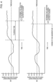
  • Fig. 4(a) and Fig. 4(b) each schematically illustrate a transition of variation in the proportion of coarse particles in coal (particle size of coal) crushed by the crushers 2a to 2c with respect to a target proportion of coarse particles (target particle size ratio), and also illustrate timing when it is determined that the variation exceeds a threshold (3.0 mass%).
  • Fig. 4(a) illustrates the case in which the determination is made by (1) described above
  • Fig. 4(b) illustrates the case in which the determination is made by (2) described above.
  • a time (tolerance time) is set and when variation in the particle size of coal continues to exceed the threshold for longer than the tolerance time, it can be determined that "variation in the particle size of coal exceeds the threshold due to an internal factor of the crushers 2a to 2c".
  • this tolerance time is set by taking into consideration, for example, a maximum length of time over which significant variation (variation exceeding the threshold) in the particle size of coal continues due to a factor on the supply side of raw materials. Since the tolerance time varies depending on the speed of feeding a pile of coal stored in the yard, the tolerance time is simply required to be appropriately set by taking this into consideration. It is preferable to set the maximum value of time required to feed a pile of coal among brands of coals blended.
  • the following situation is highly likely to have occurred when variation in the particle size of coal exceeds the threshold in all the blending tank lines A. That is, variation in the particle size of coal is highly likely to have exceeded the threshold due to a factor (disturbance factor) on the supply side of raw materials, that is, a factor (e.g., increase in water content caused by rainfall) that occurred when coal was stored, for example, in a yard.
  • a factor disurbance factor
  • the computation and control device 6 calculates variation over time with respect to the target particle size ratio on the basis of the particle size of coal continuously measured by the particle size analyzers 3a to 3c, and compares the variation with the threshold. Then, when variation in the particle size of coal in some (i.e., one or two) of the blending tank lines A1 to A3 exceeds the threshold, it is determined that the variation in the particle size of coal exceeds the threshold due to an internal factor of the one or two of the crushers 2a to 2c in the blending tank lines A.
  • the determination described above is made. Then, the determination result is output, or an instruction to make the variation in the particle size of coal less than or equal to the threshold by changing the crushing method of the crushers 2a to 2c on the basis of the determination result is output, and the output is displayed, for example, on the monitor 8. For example, an operator changes the crushing method of the crushers 2a to 2c on the basis of this display.
  • Table 1 shows an example of the target particle size ratio of coal (target proportion of coarse particles in coal) crushed by each of the crushers 2a to 2c in the blending tank lines A1 to A3, the threshold for variation with respect to the target particle size ratio, and variation in measured value (proportion of coarse particles) measured by each of the particle size analyzers 3a to 3c with respect to the target particle size ratio at a certain point, according to the present embodiment.
  • the particle size of coal (proportion of coarse particles) measured once per second by each of the particle size analyzers 3a to 3c is time-averaged every 10 minutes to determine the 10-minute average, which is then used as the measured value of the particle size of coal (proportion of coarse particles).
  • the coal crushing facility is one that is configured to perform the coal crushing method described above, and has three blending tank lines A1 to A3 as described above.
  • the blending tank lines A1 to A3 each include a plurality of blending tanks 1 configured to store coal, a corresponding one of the crushers 2a to 2c configured to crush coal fed from the blending tanks 1, and a corresponding one of the particle size analyzers 3a to 3c configured to measure the particle size of coal crushed by the corresponding one of the crushers 2a to 2c.
  • the blending tank lines A1 to A3 each include the controller 7 configured to regulate the crushing strength of a corresponding one of the crushers 2a to 2c.
  • the coal crushing facility includes the computation and control device 6 configured to cause the controller 7 to control the crushing strength of the corresponding one of the crushers 2a to 2c, and determine variation in the particle size of coal on the basis of the particle size of coal measured by the particle size analyzer 3.
  • the computation and control device 6 causes the controller 7 to control the crushing strength of the corresponding one of the crushers 2a to 2c, on the basis of a predetermined relation between the crushing strength for crushing coal with the corresponding one of the crushers 2a to 2c and the particle size of crushed coal, in such a way that the particle size of coal measured by the corresponding one of the particle size analyzers 3a to 3c becomes equal to the target particle size ratio.
  • Fig. 5 illustrates the particle size analyzers 3a to 3c and how they are used in the coal crushing facility according to the present embodiment.
  • the particle size analyzers 3a to 3c each include a CCD camera 30 configured to capture an image of coal, and a particle size calculating device 31 configured to process the image captured by the CCD camera 30 and calculate the particle size of coal (proportion of coarse particles) on the basis of the image.
  • the CCD camera 30 is installed above a coal layer (or near the surface of a coal layer) being conveyed by the conveyor 5, and captures an image of the surface of the coal layer being conveyed.
  • the height of installation of the CCD camera 30 is not particularly limited.
  • the CCD camera 30 may be installed at any position from which coal particles in the surface of the coal layer can be fully observed (e.g., at a height of about 500 mm from the surface of the coal layer) depending on the performance of the camera or lens.
  • the shutter speed of the camera may be selected appropriately in accordance with, for example, the speed of the conveyor belt and the range of field of view.
  • the surface of the coal layer conveyed by the conveyor 5 is not flat, but has unevenness and does not have a constant height. Accordingly, a camera lens with a large depth of focus is used with the CCD camera 30 (i.e., optical design is made to accommodate height displacement resulting from the unevenness). At the same time, the exposure time is reduced, and a stroboscopic light source (not shown) capable of instantaneously emitting light is used to provide light.
  • a clear image that is in focus throughout the image capturing range can be obtained, and the proportion of coarse particles can be accurately measured by image processing and particle size calculation based on the image processing, described below.
  • the particle size analyzers 3a to 3c are preferably installed downstream of the crushers 2a to 2c at a certain distance (e.g., at a distance of about 1 m to 2 m) therefrom.
  • the image of the surface of the coal layer captured by the CCD camera 30 is transmitted to the particle size calculating device 31.
  • the particle size calculating device 31 includes an image processing unit 310 and a computing unit 311.
  • the image transmitted from the CCD camera 30 is subjected to image processing by the image processing unit 310. This enables extraction of coarse particles, and the computing unit 311 calculates the proportion of coarse particles on the basis of the extraction of coarse particles.
  • the proportion of coarse particles is transmitted to the computation and control device 6 as a measured value of the particle size of coal, and used to control the crushers 2a to 2c and determine variation in the particle size of coal.
  • Fig. 6 illustrates an overview of a processing flow in which the proportion of coarse particles is calculated in the particle size calculating device 31 from an image captured by the CCD camera 30.
  • the particle size calculating device 31 first eliminates uneven brightness (or corrects uneven brightness). Elimination of uneven brightness is a process that eliminates uneven brightness over the entire image caused by the condition of illumination or the angle of image capturing. A technique commonly used as shading correction in image processing can be used to eliminate uneven brightness.
  • a process that emphasizes the particle boundaries to identify particles in the image is performed using the watershed method. That is, to identify adjacent particles in the binarized image, watershed processing that focuses on minute differences in brightness is performed to separate adjacent particles.
  • the areas of particle images obtained by this processing are individually calculated, and the particle diameters along the major and minor axes obtained by elliptically approximating these areas are calculated.
  • an image captured by the CCD camera 30 is subjected to image processing to calculate the proportion of coarse particles.
  • an optical device such as a three-dimensional camera, may be used to calculate the proportion of coarse particles.
  • coal crushing method and the coal crushing facility according to the present invention can be suitably used to crush coal for coke production, their application is not limited to this.
  • the coal crushing method and the coal crushing facility according to the present invention can also be used to crush coal for obtaining pulverized coal blown in through a tuyere in blast furnace operation.

Landscapes

  • Chemical & Material Sciences (AREA)
  • Organic Chemistry (AREA)
  • Oil, Petroleum & Natural Gas (AREA)
  • Engineering & Computer Science (AREA)
  • Environmental & Geological Engineering (AREA)
  • Geochemistry & Mineralogy (AREA)
  • Geology (AREA)
  • General Life Sciences & Earth Sciences (AREA)
  • Life Sciences & Earth Sciences (AREA)
  • Materials Engineering (AREA)
  • Food Science & Technology (AREA)
  • Disintegrating Or Milling (AREA)
  • Crushing And Pulverization Processes (AREA)

Abstract

An object is to provide a coal crushing method and a coal crushing facility that can accurately and quickly identify the occurrence of variation in the particle size of coal crushed by a crusher, particularly the occurrence of variation in the particle size of coal caused by an internal factor of the crusher, such as hammer wear, take appropriate measures against this, and thus can reduce variation in the particle size of crushed coal.When coal is crushed in blending tank lines A including particle size analyzers 3a to 3c configured to measure the particle size of coal crushed by crushers 2a to 2c, a relation between the crushing strength for crushing the coal with the crushers 2a to 2c and the particle size of crushed coal is determined in advance. Coal is crushed while the crushing strength of the crushers 2a to 2c is regulated, on the basis of this relation, in such a way that the particle size of coal measured by the particle size analyzers 3a to 3c becomes equal to a target particle size ratio, and variation over time in the particle size of coal measured by the particle size analyzers 3a to 3c with respect to the target particle size ratio is measured. When the variation in the particle size of coal exceeds a threshold, it is determined that the variation exceeds the threshold due to an internal factor of the crushers 2a to 2c, and the crushing method of the crushers 2a to 2c is changed.

Description

    Technical Field
  • The present invention relates to a coal crushing method and a coal crushing facility for reducing variation in the particle size of crushed coal, for example, in a coke production process.
  • Background Art
  • Coke used in blast furnaces is required to have a high strength and uniform quality (particle size and strength) to ensure gas permeability in the furnace. To produce coke having a high strength and uniform quality, it is necessary to increase the bulk density of coal charged into a coke oven so that when coal is heated and carbonized in the coke oven, coal particles are brought into firm contact. For this, it is important to optimize the particle size of coal charged into the coke oven.
  • When heated and carbonized in the coke oven, coarse coal particles having a large particle diameter are cracked at contact interfaces due to a difference in shrinkage ratio between adjacent coal particles, and this decreases the coke strength. On the other hand, fine coal particles having a small size fly up in the air when charged into the coke oven, and this decreases the bulk density. Therefore, to produce coke having a high strength and uniform quality, it is necessary, in the process of crushing coal with a crusher, to select a crushing condition in such a way that a target particle size ratio is achieved, and thus to reduce variation in particle size.
  • The particle size of coal crushed by a crusher varies depending on, for example, the gap between a repulsion plate (frictional crushing plate) and hammers of the crusher, the current value of a motor of the crusher, and the hammer rotation speed of the crusher. Therefore, regulating these values to adjust the particle size of crushed coal to a target particle size ratio is an approach that has been generally adopted.
  • Examples of conventional techniques related to the coal crushing method include methods described in Patent Literature 1 to Patent Literature 3. The method described in Patent Literature 1 involves measuring the particle size of crushed coal and regulating the gap between a repulsion plate and hammers of a crusher. The method described in Patent Literature 2 involves regulating the hammer rotation speed of a crusher. The method described in Patent Literature 3 involves using an equation representing a relation between coal crushing energy and particle size distributions before and after crushing, and regulating the current value of a crusher in accordance with the particle size and the water content of coal before crushing.
  • Citation List Patent Literature
    • PTL 1: Japanese Unexamined Patent Application Publication No. 2000-319663
    • PTL 2: Japanese Unexamined Patent Application Publication No. 2004-16983
    • PTL 3: Japanese Unexamined Patent Application Publication No. 2016-159196
    Summary of Invention Technical Problem
  • In the methods described in Patent Literature 1 and Patent Literature 2, when variation in the particle size of crushed coal is caused by an internal factor of the crusher, such as hammer wear, it is difficult to identify this fact and the corresponding crusher, and appropriate measures cannot be taken. In the method described in Patent Literature 3, even when it is difficult to crush coal under uniform crushing conditions due to such a factor as hammer wear in the crusher, adjusting the particle size of coal in response to, for example, hammer wear is difficult because the particle size of crushed coal cannot be obtained.
  • The present invention has been made to solve the problems of the conventional techniques described above. That is, the present invention aims to provide a coal crushing method and a coal crushing facility that can accurately and quickly identify the occurrence of variation in the particle size of coal crushed by a crusher, particularly the occurrence of variation in the particle size of coal caused by an internal factor of the crusher, such as hammer wear. The present invention also aims to take appropriate measures to reduce variation in the particle size of coal caused by an internal factor of the crusher, and thus to be able to reduce variation in the particle size of crushed coal.
  • Solution to Problem
    1. [1] A coal crushing method is for crushing coal in a coal crushing facility having a blending tank line including a blending tank configured to store coal, a crusher configured to crush coal fed from the blending tank, and a particle size analyzer configured to measure a particle size of coal crushed by the crusher. The coal crushing method includes determining, in advance, a relation between a crushing strength for crushing coal with the crusher and a particle size of crushed coal; crushing coal while regulating the crushing strength of the crusher, on the basis of the relation, in such a way that the particle size of coal measured by the particle size analyzer becomes equal to a target particle size ratio, and measuring variation over time in the particle size of coal measured by the particle size analyzer with respect to the target particle size ratio; and determining, when the variation exceeds a predetermined threshold, that the variation exceeds the threshold due to an internal factor of the crusher, and changing the crushing method of the crusher to make the variation less than or equal to the threshold.
    2. [2] In the coal crushing method according to [1], when the variation continues to exceed the threshold for longer than a preset time, it is determined that the variation exceeds the threshold due to an internal factor of the crusher, and the crushing method of the crusher is changed to make the variation less than or equal to the threshold.
    3. [3] In the coal crushing method according to [1], when the variation continues to exceed the threshold even after change of a coal blending plan, it is determined that the variation exceeds the threshold due to an internal factor of the crusher, and the crushing method of the crusher is changed to make the variation less than or equal to the threshold.
    4. [4] In the coal crushing method according to any one of [1] to [3], the coal crushing facility includes two or more blending tank lines; the variation is measured in each of the two or more blending tank lines; when the variation exceeds the threshold in only some of the two or more blending tank lines, it is determined that the variation exceeds the threshold due to an internal factor of the crusher in the corresponding blending tank line, and the crushing method of the crusher in the corresponding blending tank line is changed to make the variation less than or equal to the threshold; and when the variation exceeds the threshold in all the two or more blending tank lines, it is determined that the variation exceeds the threshold due to a factor in raw materials supplied to the crusher and not due to an internal factor of the crusher in the blending tank line, and no change is made to the crushing method of the crusher in the blending tank line.
    5. [5] In the coal crushing method according to any one of [1] to [4], the particle size analyzer is configured to capture and acquire an image of a surface of a coal layer conveyed by a conveyor after being crushed by the crusher, and measure a proportion of coarse particles in coal on the basis of the image.
    6. [6] In the coal crushing method according to any one of [1] to [5], the crusher is a hammer crusher, and the crushing strength of the crusher is a hammer rotation speed of the crusher.
    7. [7] In the coal crushing method according to any one of [1] to [6], the crusher is a hammer crusher, and the crushing method of the crusher is changed by changing at least one of a hammer rotation direction of the crusher and a gap between a repulsion plate and hammers of the crusher.
    8. [8] In the coal crushing method according to any one of [1] to [6], the crusher is a hammer crusher, and the crushing method of the crusher is changed by first changing a hammer rotation direction of the crusher, and when the variation exceeds the threshold even after changing the rotation direction, changing a gap between a repulsion plate and hammers of the crusher.
    9. [9] A coal crushing facility includes a blending tank line including a blending tank configured to store coal, a crusher configured to crush coal fed from the blending tank, a controller configured to regulate a crushing strength of the crusher, and a particle size analyzer configured to measure a particle size of coal crushed by the crusher; and a computation and control device configured to cause the controller to control a crushing strength of the crusher, and determine, on the basis of a particle size of coal measured by the particle size analyzer, variation in the particle size. The computation and control device is configured to cause the controller to control the crushing strength of the crusher, on the basis of a relation between a crushing strength of the crusher and a particle size of crushed coal determined in advance, in such a way that the particle size of coal measured by the particle size analyzer becomes equal to a target particle size ratio, measure variation over time in the particle size of coal measured by the particle size analyzer with respect to the target particle size ratio, determine, when the variation exceeds a predetermined threshold, that the variation exceeds the threshold due to an internal factor of the crusher, and output the determination result or an instruction to make the variation less than or equal to the threshold by changing a crushing method of the crusher on the basis of the determination result.
    10. [10] In the coal crushing facility according to [9], the computation and control device is configured to determine, when the variation continues to exceed the threshold for longer than a preset time, that the variation exceeds the threshold due to an internal factor of the crusher.
    11. [11] In the coal crushing facility according to [9], the computation and control device is configured to determine, when the variation continues to exceed the threshold even after change of a coal blending plan, that the variation exceeds the threshold due to an internal factor of the crusher.
    12. [12] In the coal crushing facility according to any one of [9] to [11], the coal crushing facility includes two or more blending tank lines; the computation and control device is configured to measure the variation in each of the two or more blending tank lines; the computation and control device is configured to determine, when the variation exceeds the threshold in only some of the two or more blending tank lines, that the variation exceeds the threshold due to an internal factor of the crusher in the corresponding blending tank line, and change the crushing method of the crusher in the corresponding blending tank line to make the variation less than or equal to the threshold; and the computation and control device is configured to determine, when the variation exceeds the threshold in all the two or more blending tank lines, that the variation exceeds the threshold due to a factor in raw materials supplied to the crusher and not due to an internal factor of the crusher in the blending tank line, and make no change to the crushing method of the crusher in the blending tank line.
    13. [13] In the coal crushing facility according to any one of [9] to [12], the particle size analyzer is configured to capture an image of a surface of a coal layer conveyed by a conveyor after being crushed by the crusher, and measure a proportion of coarse particles in coal on the basis of the image.
    14. [14] In the coal crushing facility according to any one of [9] to [13], the crusher is a hammer crusher, and the crushing strength of the crusher is a hammer rotation speed of the crusher.
    15. [15] In the coal crushing facility according to any one of [9] to [14], the crusher is a hammer crusher, and the crushing method of the crusher is changed by changing at least one of a hammer rotation direction of the crusher and a gap between a repulsion plate and hammers of the crusher. Advantageous Effects of Invention
  • The coal crushing method and the coal crushing facility according to the present invention can accurately and quickly identify the occurrence of variation in the particle size of coal crushed by the crusher, particularly the occurrence of variation in the particle size of coal caused by an internal factor of the crusher, such as hammer wear. Appropriate measures can thus be taken to reduce variation in the particle size of coal caused by an internal factor of the crusher. Therefore, variation in the particle size of coal crushed by the crusher can be reduced, and it is possible to produce coke having a high strength and uniform quality.
  • Brief Description of Drawings
    • [Fig. 1] Fig. 1 is an explanatory diagram schematically illustrating an example of a coal crushing facility for coke production to which a coal crushing method and a coal crushing facility according to the present invention are applied.
    • [Fig. 2] Fig. 2 is a graph schematically illustrating a relation between the coal crushing strength of a crusher and the particle size of crushed coal.
    • [Fig. 3] Fig. 3(a) to Fig. 3(c) are graphs each illustrating an exemplary relation between the hammer rotation speed (crushing strength) of a crusher in one of blending tank lines A1 to A3 illustrated in Fig. 1 and the proportion of coarse particles of crushed coal (particle size of crushed coal).
    • [Fig. 4] Fig. 4 presents graphs each schematically illustrating a transition of variation in the proportion of coarse particles in coal (particle size of coal) crushed by a crusher, with respect to a target proportion of coarse particles (target particle size ratio), and also illustrate timing when it is determined that the variation exceeds a threshold.
    • [Fig. 5] Fig. 5 is an explanatory diagram illustrating an exemplary particle size analyzer and how it is used in the coal crushing facility according to the present invention.
    • [Fig. 6] Fig. 6 is an explanatory diagram illustrating a processing flow in which the proportion of coarse particles in coal (particle size of coal) is measured by a particle size analyzer in the coal crushing method and the coal crushing facility according to the present invention. Description of Embodiments
  • Hereinafter, embodiments of a coal crushing method and a coal crushing facility according to the present invention will be described in detail with reference to the drawings.
  • Fig. 1 is an explanatory diagram schematically illustrating a coal crushing facility for coke production to which a coal crushing method and a coal crushing facility according to the present embodiment are applied. Generally, a coal crushing facility for coke production has one or more blending tank lines (coal crushing lines). The coal crushing facility according to the present embodiment illustrated in Fig. 1 has three blending tank lines A1 to A3 where coal is divided by the level of the Hardgrove grindability index (HGI) into three groups (HGI: high, HGI: medium, and HGI: low) and crushed separately. In the present embodiment, coal is subjected to a crushing process for each level of the HGI in the plurality of blending tank lines A. However, the usage of the plurality of blending tank lines A1 to A3 in the coal crushing method and the coal crushing facility according to the present invention is not limited to this.
  • The blending tank lines A1 to A3 each include a plurality of blending tanks 1 configured to store coal, a corresponding one of crushers 2a to 2c configured to crush coal fed from the blending tanks 1, and a corresponding one of particle size analyzers 3a to 3c configured to measure the particle size of coal crushed by the corresponding one of the crushers 2a to 2c.
  • Coal is stored in a coal yard by brand. Of the coal stored, a portion to be used is conveyed by a conveyor (conveyor belt) by brand and stored in the blending tanks 1. Generally, the brand of coal stored in the plurality of blending tanks 1 in one of the blending tank lines A differs from the brand of coal stored in the plurality of blending tanks 1 in another of the blending tank lines A.
  • When a blending plan (blending ratio plan) for coal to be charged into a coke oven is determined, a predetermined brand of coal is fed from the plurality of blending tanks 1 in each of the blending tank lines A by a predetermined amount (i.e., a predetermined amount per unit time) in accordance with the blending plan. The fed coal is conveyed by a conveyor 4 (conveyor belt) to each of the crushers 2a to 2c and crushed into a predetermined particle size. The coal crushed by each of the crushers 2a to 2c is further conveyed by a conveyor 5 (conveyor belt) to the coke oven (or facility on the entry side of the coke oven). While the coal is being conveyed by the conveyor 5, the particle size of the coal is continuously measured by a corresponding one of the particle size analyzers 3a to 3c. After being subjected to a crushing process in the blending tank lines A1 to A3, the coals are mixed, subjected to a necessary process (e.g., moisture controlling process), and charged into the coke oven.
  • The particle size of coal measured by each of the particle size analyzers 3a to 3c and the method of this measurement are not particularly limited. The particle size of coal measured by each of the particle size analyzers 3a to 3c is not the distribution of all particle sizes, but may be the proportion of coarse particles in coal (e.g., the proportion of coarse particles having a particle diameter of greater than or equal to 6 mm). That is, the proportion of coarse particles can represent the particle size distributions of coal and, as described below, the proportion of coarse particles in coal has a high correlation with the crushing strength of each of the crushers 2a to 2c. As described above, the presence of coarse particles in coal decreases the coke strength. Therefore, measuring the proportion of coarse particles to control the particle size is also of significance in ensuring the coke strength. As described below, the proportion of coarse particles in coal can be easily and highly precisely measured online by capturing, for example with a CCD camera, an image of the surface of a coal layer being conveyed by the conveyor 5, and processing the image to calculate the particle size. This method for measuring the proportion of coarse particles in coal will be described in detail later on. Generally, when the particle size analyzers 3a to 3c measure the proportion of coarse particles in coal, the lower limit of the particle diameter (e.g., 6 mm) is determined in a particle diameter range of 6 mm to 50 mm. Then, particles having a particle diameter of greater than or equal to the lower limit are defined as coarse particles, and the proportion of the coarse particles (i.e., the proportion to the total amount of coal) is determined. The reason for which the lower limit of the particle diameter of coarse particles is set within the range described above is that coarse particles of this diameter can be advantageously measured by a camera-type measuring means, and are less frequently stacked in layers among the coarse particles because of their small proportion. When the lower limit of the particle diameter of coarse particles is set to a value less than 6 mm, it is preferable to use, for example, a laser diffraction method for the measurement.
  • The type of the crushers 2a to 2c is not particularly limited, and hammer crushers, impact crushers, roll crushers, or others can be used. However, hammer crushers are often used as the crushers 2a to 2c. In the following description, an example where hammer crushers are mainly used will be described.
  • In the coal crushing method and the coal crushing facility according to the present embodiment, a basic form of crushing coal is as follows. First, a relation between the crushing strength for crushing coal with each of the crushers 2a to 2c and the particle size of crushed coal (preferably the proportion of coarse particles; the same applies hereinafter), that is, a relation such as that schematically illustrated in Fig. 2, is determined in advance, on the basis of the result of a test or actual operation carried out beforehand. Then, on the basis of this relation, coal is crushed while each of controllers 7 regulates (controls) the crushing strength of a corresponding one of the crushers 2a to 2c in such a way that the particle size of coal measured by a corresponding one of the particle size analyzers 3a to 3c becomes equal to a target particle size ratio (target particle size ratio of crushed coal; the same applies hereinafter). Here, the crushing strength for crushing coal with each of the crushers 2a to 2c is, for example, a hammer rotation speed when the crushers 2a to 2c are hammer crushers. Accordingly, when the crushing strength is a hammer rotation speed, the relation between the hammer rotation speed of each of the crushers 2a to 2c and the particle size of crushed coal is determined in advance, and each of the controllers 7 regulates (controls) the hammer rotation speed of a corresponding one of the crushers 2a to 2c, as described above, on the basis of this relation.
  • Specifically, a computation and control device 6 compares the particle size of coal measured by each of the particle size analyzers 3a to 3c with a target particle size ratio, and determines the hammer rotation speed for achieving the target particle size ratio on the basis of the relation determined in advance. The computation and control device 6 is, for example, a general-purpose computer, such as a workstation or a personal computer. The computation and control device 6 causes each of the controllers 7 to rotate the hammers of a corresponding one of the crushers 2a to 2c at the hammer rotation speed to crush coal.
  • When the crushers 2a to 2c are crushers of other types, the crushing strength is as follows. For example, when the crushers 2a to 2c are roll crushers, the crushing strength is a roll rotation speed, whereas when the crushers 2a to 2c are impact crushers, the crushing strength is a rotor rotation speed.
  • The relation between the crushing strength of each of the crushers 2a to 2c and the particle size of crushed coal varies depending on the HGI of coal. Therefore, when coals with different HGIs are separately crushed in the blending tank lines A1 to A3 as in the present embodiment illustrated in Fig. 1, it is preferable to determine, for each HGI, the relation between the crushing strength of a corresponding one of the crushers 2a to 2c and the particle size of crushed coal. Fig. 3(a) to Fig. 3(c) are graphs each illustrating an exemplary relation between the crushing strength (hammer rotation speed) of one of the crushers 2a to 2c that crush coals with high, medium, and low HGIs in the blending tank lines A1 to A3, and the particle size of crushed coal (proportion of coarse particles in coal). For example, the high HGI is greater than or equal to 80 and less than 100, the medium HGI is greater than or equal to 60 and less than 80, and the low HGI is greater than or equal to 40 and less than 60. Note that the particle size of crushed coal (proportion of coarse particles in coal) illustrated in Fig. 3(a) to Fig. 3(c) is the proportion of coarse particles having a particle diameter of greater than or equal to 6 mm.
  • In the coal crushing method and the coal crushing facility according to the present embodiment, in a coal crushing process performed as described above, variation over time in the particle size of coal measured by each of the particle size analyzers 3a to 3c, with respect to a target particle size ratio, is measured. Then, when the variation in the particle size of coal exceeds a threshold, it is determined that the variation in the particle size of coal exceeds the threshold due to an internal factor of a corresponding one of the crushers 2a to 2c, and the crushing method of the corresponding one of the crushers 2a to 2c is changed. That is, when variation in the particle size of coal exceeds a threshold, it is determined that an appropriate crushing condition is not satisfied in the crusher, and the crushing method of the corresponding one of the crushers 2a to 2c is changed accordingly.
  • Here, "variation in the particle size of coal exceeds a threshold" means that variation on the positive or negative side with respect to a target particle size ratio exceeds the threshold. For example, when the target particle size ratio (proportion of coarse particles) is 10 mass% and the threshold is 3 mass%, then variation with respect to the target particle size ratio exceeds the threshold when the particle size of crushed coal (proportion of coarse particles) is greater than 13 mass% or less than 7 mass%. Also, an internal factor of any of the crushers 2a to 2c where variation in the particle size of crushed coal occurs refers to, for example, wear or malfunction of crushing means of the crusher (e.g., a repulsion plate or hammers of a hammer crusher).
  • Also, the "crushing method of the crusher" to be changed is a mechanical setting condition or an operating method for crushing coal. When the crushers 2a to 2c are hammer crushers, examples of the "crushing method of the crusher" include (i) hammer rotation direction and (ii) gap between a repulsion plate (frictional crushing plate) and hammers. When the crushers 2a to 2c are crushers of other types, the "crushing method of the crusher" is as follows. For example, when the crushers 2a to 2c are roll crushers, the "crushing method of the crusher" is a gap between rolls, whereas when the crushers 2a to 2c are impact crushers, the "crushing method of the crusher" is a gap between a striking plate and an impact plate.
  • When the crushers 2a to 2c are hammer crushers, it is preferable to give priority to changing the crushing method (i). With variation in the particle size of coal cannot be corrected after changing the crushing method (i), then the crushing method (ii) is changed. This is because as a form of changing the crushing method of the crushers 2a to 2c, changing (i) is advantageous in that it is simpler and quicker than changing (ii). Giving priority to changing (i) is also preferable because when variation in the particle size of coal is caused, for example, by relatively minor wear of hammers of the crushers 2a to 2c, the variation is often corrected by changing (i).
  • Variation over time in the measured particle size of coal with respect to the target particle size ratio may be time-averaged variation over a certain period of time. For example, when the particle size is measured once per second by the particle size analyzers 3a to 3c to determine variation with respect to the target particle size ratio, the 10-minute average of variation may be determined every 10 minutes and compared with the threshold.
  • The computation and control device 6 calculates variation over time with respect to the target particle size ratio on the basis of the particle size of coal continuously measured by the particle size analyzers 3a to 3c, and compares the variation with the threshold. When the variation in the particle size of coal continues to exceed the threshold, it is determined that the variation in the particle size of coal exceeds the threshold due to an internal factor of the crushers 2a to 2c. Then, the determination result is output, or an instruction to make the variation in the particle size of coal less than or equal to the threshold by changing the crushing method of the crushers 2a to 2c on the basis of the determination result is output, and the output is displayed, for example, on a monitor 8. For example, an operator changes the crushing method of the crushers 2a to 2c on the basis of this display. Alternatively, the crushing method of the crushers 2a to 2c may be automatically changed by directly entering, into the crushers 2a to 2c, the output of the instruction to change the crushing method of the crushers 2a to 2c.
  • The threshold for variation in the particle size of coal with respect to the target particle size ratio may be set to any value depending on, for example, the precision of the particle size analyzer or the HGI of coal. For the proportion of coarse particles in coal, however, the threshold is preferably set, for example, within a range of about 1.0 mass% to 3.0 mass% depending on the HGI of coal.
  • The determination that variation in the particle size of coal exceeds the threshold is preferably made when, for example, (1) variation in the particle size of coal continues to exceed the threshold for longer than a time (tolerance time) set in advance. Alternatively, the determination that variation in the particle size of coal exceeds the threshold is preferably made when (2) variation in the particle size of coal continues to exceed the threshold even after change of a coal blending plan. Note that the change of a coal blending plan refers to changing the type (brand) or quantity of coal to be fed from the blending tanks 1 in each blending tank line A from the perspective of, for example, the quality or the cost of raw materials of coke to be produced. The coal blending plan may be changed up to multiple times a day.
  • Fig. 4(a) and Fig. 4(b) each schematically illustrate a transition of variation in the proportion of coarse particles in coal (particle size of coal) crushed by the crushers 2a to 2c with respect to a target proportion of coarse particles (target particle size ratio), and also illustrate timing when it is determined that the variation exceeds a threshold (3.0 mass%). Fig. 4(a) illustrates the case in which the determination is made by (1) described above, and Fig. 4(b) illustrates the case in which the determination is made by (2) described above.
  • When the determination is made by (1) described above, a time (tolerance time) is set and when variation in the particle size of coal continues to exceed the threshold for longer than the tolerance time, it can be determined that "variation in the particle size of coal exceeds the threshold due to an internal factor of the crushers 2a to 2c". Generally, this tolerance time is set by taking into consideration, for example, a maximum length of time over which significant variation (variation exceeding the threshold) in the particle size of coal continues due to a factor on the supply side of raw materials. Since the tolerance time varies depending on the speed of feeding a pile of coal stored in the yard, the tolerance time is simply required to be appropriately set by taking this into consideration. It is preferable to set the maximum value of time required to feed a pile of coal among brands of coals blended.
  • When the determination is made by (2) described above, it is determined, when variation in the particle size of coal continues to exceed the threshold even after change of a coal blending plan, that "variation in the particle size of coal exceeds the threshold due to an internal factor of the crushers 2a to 2c". This is because when significant variation (variation exceeding the threshold) in the particle size of coal continues due to a factor on the supply side of raw materials, the significant variation is often corrected by changing the coal blending plan.
  • When the coal crushing facility has two or more blending tank lines A as in the present embodiment illustrated in Fig. 1, the following situation is highly likely to have occurred when variation in the particle size of coal exceeds the threshold in all the blending tank lines A. That is, variation in the particle size of coal is highly likely to have exceeded the threshold due to a factor (disturbance factor) on the supply side of raw materials, that is, a factor (e.g., increase in water content caused by rainfall) that occurred when coal was stored, for example, in a yard. Therefore, it is preferable to determine that variation in the particle size of coal exceeds the threshold due to a factor (disturbance factor) on the supply side of raw materials, and is preferable not to determine that "variation in the particle size of coal is caused by an internal factor of the crushers 2a to 2c".
  • When a determination, such as that described above, is made, the computation and control device 6 calculates variation over time with respect to the target particle size ratio on the basis of the particle size of coal continuously measured by the particle size analyzers 3a to 3c, and compares the variation with the threshold. Then, when variation in the particle size of coal in some (i.e., one or two) of the blending tank lines A1 to A3 exceeds the threshold, it is determined that the variation in the particle size of coal exceeds the threshold due to an internal factor of the one or two of the crushers 2a to 2c in the blending tank lines A. For example, when variation in the particle size of coal continues to exceed the threshold for longer than the tolerance time set in advance, or variation in the particle size of coal continues to exceed the threshold even after change of a coal blending plan, the determination described above is made. Then, the determination result is output, or an instruction to make the variation in the particle size of coal less than or equal to the threshold by changing the crushing method of the crushers 2a to 2c on the basis of the determination result is output, and the output is displayed, for example, on the monitor 8. For example, an operator changes the crushing method of the crushers 2a to 2c on the basis of this display.
  • When variation in the particle size of coal in all the blending tank lines A1 to A3 exceeds the threshold, it is determined that the variation in the particle size of coal exceeds the threshold due to a factor (disturbance factor) on the supply side of raw materials, and the determination result is displayed, for example, on the monitor 8. There is no particular output from the computation and control device 6.
  • Table 1 shows an example of the target particle size ratio of coal (target proportion of coarse particles in coal) crushed by each of the crushers 2a to 2c in the blending tank lines A1 to A3, the threshold for variation with respect to the target particle size ratio, and variation in measured value (proportion of coarse particles) measured by each of the particle size analyzers 3a to 3c with respect to the target particle size ratio at a certain point, according to the present embodiment. In this example, the particle size of coal (proportion of coarse particles) measured once per second by each of the particle size analyzers 3a to 3c is time-averaged every 10 minutes to determine the 10-minute average, which is then used as the measured value of the particle size of coal (proportion of coarse particles). In the example shown in Table 1, variation in the particle size of crushed coal at a certain point is within the threshold in the crushers 2a and 2b of the blending tank lines A1 and A2, but exceeds the threshold (3.0 mass%) in the crusher 2c of the blending tank line A3.
  • For example, when the determination is made by (2) described above, when variation in the particle size of crushed coal in the blending tank line A3 continues to exceed the threshold, as shown in Table 1, even after the change of a coal blending plan, it is determined that "variation in the particle size of coal exceeds the threshold due to an internal factor of the crusher 2c" in the blending tank line A3, and the crushing method of the crusher 2c is changed.
  • When variation in the particle size of crushed coal in all the blending tank lines A1 to A3 continues to exceed the threshold shown in Table 1 even after change of the coal blending plan, it is determined, as described, that the variation in the particle size of coal exceeds the threshold due to a factor (disturbance factor) on the supply side of raw materials. That is, it is preferable not to determine that "variation in the particle size of coal exceeds the threshold due to an internal factor of the crushers 2a to 2c", and is preferable that there be no particular output from the computation and control device 6. However, when variation in the particle size of coal continues to exceed the threshold even after the coal blending plan is changed again thereafter, it may be determined that "variation in the particle size of coal exceeds the threshold due to an internal factor of the crushers 2a to 2c". Table 1]
    Blending Tank Line A1 A2 A3
    Crusher 2a
    2b
    2c
    Target Proportion of Coarse Particles (mass%) 2.0 14.0 10.0
    Variation from Target Proportion of Coarse Particles (mass%)*1 1.04 1.49 3.37
    Threshold for Variation from Target Proportion of Coarse Particles (mass%) 3.00 3.00 3.00
    *1) Variation in measured value (proportion of coarse particles) measured by the particle size analyzer from the target proportion of coarse particles at a certain point
  • The coal crushing facility according to the present embodiment is one that is configured to perform the coal crushing method described above, and has three blending tank lines A1 to A3 as described above. The blending tank lines A1 to A3 each include a plurality of blending tanks 1 configured to store coal, a corresponding one of the crushers 2a to 2c configured to crush coal fed from the blending tanks 1, and a corresponding one of the particle size analyzers 3a to 3c configured to measure the particle size of coal crushed by the corresponding one of the crushers 2a to 2c. The blending tank lines A1 to A3 each include the controller 7 configured to regulate the crushing strength of a corresponding one of the crushers 2a to 2c. The coal crushing facility includes the computation and control device 6 configured to cause the controller 7 to control the crushing strength of the corresponding one of the crushers 2a to 2c, and determine variation in the particle size of coal on the basis of the particle size of coal measured by the particle size analyzer 3.
  • The computation and control device 6 causes the controller 7 to control the crushing strength of the corresponding one of the crushers 2a to 2c, on the basis of a predetermined relation between the crushing strength for crushing coal with the corresponding one of the crushers 2a to 2c and the particle size of crushed coal, in such a way that the particle size of coal measured by the corresponding one of the particle size analyzers 3a to 3c becomes equal to the target particle size ratio. Then, variation over time in the particle size of coal measured by each of the particle size analyzers 3a to 3c with respect to the target particle size ratio is measured, and when the variation in the particle size of coal exceeds the threshold, it is determined that the variation in the particle size of coal exceeds the threshold due to an internal factor of the corresponding one of the crushers 2a to 2c. Then, the determination result, or an instruction based on the determination result to change the crushing method of the corresponding one of the crushers 2a to 2c, is output. The details of the configuration, function, and usage of the coal crushing facility are as described above.
  • Hereinafter, a method for measuring the particle size of coal (proportion of coarse particles) with the particle size analyzers 3a to 3c will be described.
  • Fig. 5 illustrates the particle size analyzers 3a to 3c and how they are used in the coal crushing facility according to the present embodiment. The particle size analyzers 3a to 3c each include a CCD camera 30 configured to capture an image of coal, and a particle size calculating device 31 configured to process the image captured by the CCD camera 30 and calculate the particle size of coal (proportion of coarse particles) on the basis of the image.
  • The CCD camera 30 is installed above a coal layer (or near the surface of a coal layer) being conveyed by the conveyor 5, and captures an image of the surface of the coal layer being conveyed. The height of installation of the CCD camera 30 is not particularly limited. The CCD camera 30 may be installed at any position from which coal particles in the surface of the coal layer can be fully observed (e.g., at a height of about 500 mm from the surface of the coal layer) depending on the performance of the camera or lens. The shutter speed of the camera may be selected appropriately in accordance with, for example, the speed of the conveyor belt and the range of field of view.
  • The surface of the coal layer conveyed by the conveyor 5 is not flat, but has unevenness and does not have a constant height. Accordingly, a camera lens with a large depth of focus is used with the CCD camera 30 (i.e., optical design is made to accommodate height displacement resulting from the unevenness). At the same time, the exposure time is reduced, and a stroboscopic light source (not shown) capable of instantaneously emitting light is used to provide light. Thus, a clear image that is in focus throughout the image capturing range can be obtained, and the proportion of coarse particles can be accurately measured by image processing and particle size calculation based on the image processing, described below.
  • It is known that when a layered, powder and granular material is subjected to vibration, coarse particles tend to collect on the surface layer side because of the Brazil nut effect. Coarse particles of coal conveyed on the conveyor 5 after being crushed are initially embedded in the layer. However, since the coal layer conveyed by the conveyor 5 is subjected to vibration, the coarse particles are moved to the surface layer side by the Brazil nut effect and exposed. Thus, the particle size distribution in the captured image of the surface of the coal layer becomes closer to the particle size distribution in the entire coal layer. To measure the particle size after the coarse particles in the coal layer are moved to the surface layer side by the Brazil nut effect, the particle size analyzers 3a to 3c are preferably installed downstream of the crushers 2a to 2c at a certain distance (e.g., at a distance of about 1 m to 2 m) therefrom.
  • The image of the surface of the coal layer captured by the CCD camera 30 is transmitted to the particle size calculating device 31. The particle size calculating device 31 includes an image processing unit 310 and a computing unit 311. The image transmitted from the CCD camera 30 is subjected to image processing by the image processing unit 310. This enables extraction of coarse particles, and the computing unit 311 calculates the proportion of coarse particles on the basis of the extraction of coarse particles. The proportion of coarse particles is transmitted to the computation and control device 6 as a measured value of the particle size of coal, and used to control the crushers 2a to 2c and determine variation in the particle size of coal.
  • Fig. 6 illustrates an overview of a processing flow in which the proportion of coarse particles is calculated in the particle size calculating device 31 from an image captured by the CCD camera 30.
  • When an image captured by the CCD camera 30 is received, the particle size calculating device 31 first eliminates uneven brightness (or corrects uneven brightness). Elimination of uneven brightness is a process that eliminates uneven brightness over the entire image caused by the condition of illumination or the angle of image capturing. A technique commonly used as shading correction in image processing can be used to eliminate uneven brightness. After the image is binarized, a process (particle separation) that emphasizes the particle boundaries to identify particles in the image is performed using the watershed method. That is, to identify adjacent particles in the binarized image, watershed processing that focuses on minute differences in brightness is performed to separate adjacent particles. The areas of particle images obtained by this processing are individually calculated, and the particle diameters along the major and minor axes obtained by elliptically approximating these areas are calculated. Then, by identifying only particles with minor axes that are greater than or equal to a threshold, only coarse particles with large particle sizes are extracted from coal particles. For the extracted (identified) coarse particles, the weight of each particle is calculated from the particle diameter. From the sum total of the weights, the mass of coarse particles in coal is calculated, and the proportion of coarse particles (particle size of coal) is calculated from the result of the calculation. The proportion of coarse particles (particle size of coal) calculated as described above is transmitted to the computation and control device 6 in real time.
  • In the embodiments described above, an image captured by the CCD camera 30 is subjected to image processing to calculate the proportion of coarse particles. Alternatively, an optical device, such as a three-dimensional camera, may be used to calculate the proportion of coarse particles.
  • Although the coal crushing method and the coal crushing facility according to the present invention can be suitably used to crush coal for coke production, their application is not limited to this. For example, the coal crushing method and the coal crushing facility according to the present invention can also be used to crush coal for obtaining pulverized coal blown in through a tuyere in blast furnace operation.
  • Reference Signs List
    • 1: blending tank
    • 2a, 2b, 2c: crusher
    • 3a, 3b, 3c: particle size analyzer
    • 4, 5: conveyor
    • 6: computation and control device
    • 7: controller
    • 8: monitor
    • 30: CCD camera
    • 31: particle size calculating device
    • 310: image processing unit
    • 311: computing unit
    • A1, A2, A3: blending tank line

Claims (15)

  1. A coal crushing method for crushing coal in a coal crushing facility having a blending tank line including a blending tank configured to store coal, a crusher configured to crush coal fed from the blending tank, and a particle size analyzer configured to measure a particle size of coal crushed by the crusher, the coal crushing method comprising:
    determining, in advance, a relation between a crushing strength for crushing coal with the crusher and a particle size of crushed coal;
    crushing coal while regulating the crushing strength of the crusher, on the basis of the relation, in such a way that the particle size of coal measured by the particle size analyzer becomes equal to a target particle size ratio, and measuring variation over time in the particle size of coal measured by the particle size analyzer with respect to the target particle size ratio; and
    determining, when the variation exceeds a predetermined threshold, that the variation exceeds the threshold due to an internal factor of the crusher, and changing the crushing method of the crusher to make the variation less than or equal to the threshold.
  2. The coal crushing method according to Claim 1, wherein when the variation continues to exceed the threshold for longer than a preset time, it is determined that the variation exceeds the threshold due to an internal factor of the crusher, and the crushing method of the crusher is changed to make the variation less than or equal to the threshold.
  3. The coal crushing method according to Claim 1, wherein when the variation continues to exceed the threshold even after change of a coal blending plan, it is determined that the variation exceeds the threshold due to an internal factor of the crusher, and the crushing method of the crusher is changed to make the variation less than or equal to the threshold.
  4. The coal crushing method according to any one of Claims 1 to 3, wherein the coal crushing facility includes two or more blending tank lines;
    the variation is measured in each of the two or more blending tank lines;
    when the variation exceeds the threshold in only some of the two or more blending tank lines, it is determined that the variation exceeds the threshold due to an internal factor of the corresponding crusher in the blending tank line, and the crushing method of the crusher in the corresponding blending tank line is changed to make the variation less than or equal to the threshold; and
    when the variation exceeds the threshold in all the two or more blending tank lines, it is determined that the variation exceeds the threshold due to a factor in raw materials supplied to the crusher and not due to an internal factor of the crusher in the blending tank line, and no change is made to the crushing method of the crusher in the blending tank line.
  5. The coal crushing method according to any one of Claims 1 to 4, wherein the particle size analyzer is configured to capture and acquire an image of a surface of a coal layer conveyed by a conveyor after being crushed by the crusher, and measure a proportion of coarse particles in coal on the basis of the image.
  6. The coal crushing method according to any one of Claims 1 to 5, wherein the crusher is a hammer crusher, and the crushing strength of the crusher is a hammer rotation speed of the crusher.
  7. The coal crushing method according to any one of Claims 1 to 6, wherein the crusher is a hammer crusher, and the crushing method of the crusher is changed by changing at least one of a hammer rotation direction of the crusher and a gap between a repulsion plate and hammers of the crusher.
  8. The coal crushing method according to any one of Claims 1 to 6, wherein the crusher is a hammer crusher, and the crushing method of the crusher is changed by first changing a hammer rotation direction of the crusher, and when the variation exceeds the threshold even after changing the rotation direction, changing a gap between a repulsion plate and hammers of the crusher.
  9. A coal crushing facility comprising:
    a blending tank line including a blending tank configured to store coal, a crusher configured to crush coal fed from the blending tank, a controller configured to regulate a crushing strength of the crusher, and a particle size analyzer configured to measure a particle size of coal crushed by the crusher; and
    a computation and control device configured to cause the controller to control a crushing strength of the crusher, and determine, on the basis of a particle size of coal measured by the particle size analyzer, variation in the particle size,
    wherein the computation and control device is configured to cause the controller to control the crushing strength of the crusher, on the basis of a relation between a crushing strength of the crusher and a particle size of crushed coal determined in advance, in such a way that the particle size of coal measured by the particle size analyzer becomes equal to a target particle size ratio, measure variation over time in the particle size of coal measured by the particle size analyzer with respect to the target particle size ratio, determine, when the variation exceeds a predetermined threshold, that the variation exceeds the threshold due to an internal factor of the crusher, and output the determination result or an instruction to make the variation less than or equal to the threshold by changing a crushing method of the crusher on the basis of the determination result.
  10. The coal crushing facility according to Claim 9, wherein the computation and control device is configured to determine, when the variation continues to exceed the threshold for longer than a preset time, that the variation exceeds the threshold due to an internal factor of the crusher.
  11. The coal crushing facility according to Claim 9, wherein the computation and control device is configured to determine, when the variation continues to exceed the threshold even after change of a coal blending plan, that the variation exceeds the threshold due to an internal factor of the crusher.
  12. The coal crushing facility according to any one of Claims 9 to 11, wherein the coal crushing facility includes two or more blending tank lines;
    the computation and control device is configured to measure the variation in each of the two or more blending tank lines;
    the computation and control device is configured to determine, when the variation exceeds the threshold in only some of the two or more blending tank lines, that the variation exceeds the threshold due to an internal factor of the crusher in the corresponding blending tank line, and change the crushing method of the crusher in the corresponding blending tank line to make the variation less than or equal to the threshold; and
    the computation and control device is configured to determine, when the variation exceeds the threshold in all the two or more blending tank lines, that the variation exceeds the threshold due to a factor in raw materials supplied to the crusher and not due to an internal factor of the crusher in the blending tank line, and make no change to the crushing method of the crusher in the blending tank line.
  13. The coal crushing facility according to any one of Claims 9 to 12, wherein the particle size analyzer is configured to capture an image of a surface of a coal layer conveyed by a conveyor after being crushed by the crusher, and measure a proportion of coarse particles in coal on the basis of the image.
  14. The coal crushing facility according to any one of Claims 9 to 13, wherein the crusher is a hammer crusher, and the crushing strength of the crusher is a hammer rotation speed of the crusher.
  15. The coal crushing facility according to any one of Claims 9 to 14, wherein the crusher is a hammer crusher, and the crushing method of the crusher is changed by changing at least one of a hammer rotation direction of the crusher and a gap between a repulsion plate and hammers of the crusher.
EP22904021.7A 2021-12-09 2022-11-22 COAL GRINDING PROCESS AND GRINDING PLANT Pending EP4420787A4 (en)

Applications Claiming Priority (2)

Application Number Priority Date Filing Date Title
JP2021200407 2021-12-09
PCT/JP2022/043180 WO2023106090A1 (en) 2021-12-09 2022-11-22 Coal grinding method and grinding facility

Publications (2)

Publication Number Publication Date
EP4420787A1 true EP4420787A1 (en) 2024-08-28
EP4420787A4 EP4420787A4 (en) 2025-01-22

Family

ID=85872888

Family Applications (1)

Application Number Title Priority Date Filing Date
EP22904021.7A Pending EP4420787A4 (en) 2021-12-09 2022-11-22 COAL GRINDING PROCESS AND GRINDING PLANT

Country Status (2)

Country Link
EP (1) EP4420787A4 (en)
JP (1) JP7255766B1 (en)

Cited By (2)

* Cited by examiner, † Cited by third party
Publication number Priority date Publication date Assignee Title
CN120754943A (en) * 2025-09-05 2025-10-10 浙江洛克新材料股份有限公司 Efficient crushing and blending device for raw materials for preparing polycarbonate
CN120861255A (en) * 2025-09-25 2025-10-31 南昌矿机集团股份有限公司 Monitoring method and system for multi-stage crushing station

Families Citing this family (1)

* Cited by examiner, † Cited by third party
Publication number Priority date Publication date Assignee Title
JP7831520B2 (en) * 2024-07-11 2026-03-17 Jfeスチール株式会社 Method for grinding raw materials, method for producing coke, and apparatus for grinding raw materials

Family Cites Families (14)

* Cited by examiner, † Cited by third party
Publication number Priority date Publication date Assignee Title
JPS53121004A (en) * 1977-03-18 1978-10-23 Nippon Steel Corp Production of charging coal for manufacture of metallurgical coke
JPH0723473B2 (en) * 1985-01-16 1995-03-15 三菱化学株式会社 Coke manufacturing method
JPH06212169A (en) * 1993-01-20 1994-08-02 Mitsubishi Kasei Corp Coking coal particle size control system for coke oven operation management
US5506782A (en) * 1993-01-20 1996-04-09 Mitsubishi Chemical Corporation Operation management system for coke oven
JPH06212167A (en) * 1993-01-20 1994-08-02 Mitsubishi Kasei Corp Accuracy control system of coking coke blending in operation control of coke oven
JP3810592B2 (en) * 1999-07-28 2006-08-16 関西熱化学株式会社 Method for producing metallurgical coke
JP4299693B2 (en) * 2004-02-20 2009-07-22 新日本製鐵株式会社 Coke shrinkage measurement method and coke particle size estimation method using the same
JP2007245035A (en) * 2006-03-16 2007-09-27 Earth Technica:Kk Crushing equipment and cleaning method for crushing equipment
JP5152378B2 (en) * 2010-09-01 2013-02-27 Jfeスチール株式会社 Method for producing metallurgical coke
JP6874502B2 (en) * 2016-09-14 2021-05-19 日本製鉄株式会社 Coke strength estimation method
JP6747213B2 (en) * 2016-09-26 2020-08-26 日本製鉄株式会社 Coal crushing method
JP6867225B2 (en) * 2017-04-28 2021-04-28 株式会社アーステクニカ Impact crusher
CN108940462B (en) * 2017-05-26 2021-01-12 宝山钢铁股份有限公司 Online control method for crushing fineness of coking matched coal
JP7028213B2 (en) * 2019-03-27 2022-03-02 Jfeスチール株式会社 Coke strength measuring method, coke strength estimation method, and coke manufacturing method

Cited By (3)

* Cited by examiner, † Cited by third party
Publication number Priority date Publication date Assignee Title
CN120754943A (en) * 2025-09-05 2025-10-10 浙江洛克新材料股份有限公司 Efficient crushing and blending device for raw materials for preparing polycarbonate
CN120861255A (en) * 2025-09-25 2025-10-31 南昌矿机集团股份有限公司 Monitoring method and system for multi-stage crushing station
CN120861255B (en) * 2025-09-25 2026-01-06 南昌矿机集团股份有限公司 A monitoring method and system for a multi-stage crushing plant

Also Published As

Publication number Publication date
EP4420787A4 (en) 2025-01-22
JPWO2023106090A1 (en) 2023-06-15
JP7255766B1 (en) 2023-04-11

Similar Documents

Publication Publication Date Title
EP4420787A1 (en) Coal grinding method and grinding facility
CN115461155B (en) Grinding method and installation with material input recognition
CN104602551B (en) The grammes per square metre measurement apparatus, its measuring method, the manufacture system of tobacco sheet of tobacco sheet and its manufacture method
WO2023106090A1 (en) Coal grinding method and grinding facility
CN111515009A (en) A fully variable frequency pulverizing system and debugging method without minimum coal quantity limit
KR101480873B1 (en) Apparatus and control method for crushing with uniform size coke using in sintering process
CN108940462B (en) Online control method for crushing fineness of coking matched coal
CN107297269A (en) The control method of Material Level In Ball Mills
JP6747213B2 (en) Coal crushing method
JP6776881B2 (en) Processing equipment, methods, and programs in the milling plant
JPWO2023106090A5 (en)
JPH02157053A (en) Vertical mill control apparatus
GB2159306A (en) Crusher gap setting
JP6384438B2 (en) Method for producing sintered ore
JP7786410B2 (en) Coal crushing method and crushing equipment
DE10100331A1 (en) Grinding arrangement derives flow of flue gas from temperatures of mixed tempering material, flue gas entering flue gas channel, mixture in channel and flow of tempering material
KR100530081B1 (en) A Method for Controlling the Supply of Sinter Cake for Furnace
SU1389847A1 (en) Method of controlling the process of grinding materials in the mill
JP6179726B2 (en) Method for producing sintered ore
JP2026066873A (en) Method for adjusting the moisture content of raw materials, method for producing coke, and apparatus for adjusting the moisture content of raw materials
Fedotov et al. Application of the information measuring system to improve the feeding mechanism of a roller machine
CN117244677B (en) Control method and system for granularity of sintered fuel
KR100896569B1 (en) Split Gate Controller of Sintering Machine
KR20250089993A (en) Apparatus for measuring grain-size distribution, control system and control method for grain-size distribution using the same
JP7831520B2 (en) Method for grinding raw materials, method for producing coke, and apparatus for grinding raw materials

Legal Events

Date Code Title Description
STAA Information on the status of an ep patent application or granted ep patent

Free format text: STATUS: THE INTERNATIONAL PUBLICATION HAS BEEN MADE

PUAI Public reference made under article 153(3) epc to a published international application that has entered the european phase

Free format text: ORIGINAL CODE: 0009012

STAA Information on the status of an ep patent application or granted ep patent

Free format text: STATUS: REQUEST FOR EXAMINATION WAS MADE

17P Request for examination filed

Effective date: 20240521

AK Designated contracting states

Kind code of ref document: A1

Designated state(s): AL AT BE BG CH CY CZ DE DK EE ES FI FR GB GR HR HU IE IS IT LI LT LU LV MC ME MK MT NL NO PL PT RO RS SE SI SK SM TR

A4 Supplementary search report drawn up and despatched

Effective date: 20241223

RIC1 Information provided on ipc code assigned before grant

Ipc: C10L 5/04 20060101ALI20241217BHEP

Ipc: C10B 57/04 20060101ALI20241217BHEP

Ipc: B02C 25/00 20060101AFI20241217BHEP

DAV Request for validation of the european patent (deleted)
DAX Request for extension of the european patent (deleted)