EP4420583A2 - Staubsaugermundstück - Google Patents
Staubsaugermundstück Download PDFInfo
- Publication number
- EP4420583A2 EP4420583A2 EP24188490.7A EP24188490A EP4420583A2 EP 4420583 A2 EP4420583 A2 EP 4420583A2 EP 24188490 A EP24188490 A EP 24188490A EP 4420583 A2 EP4420583 A2 EP 4420583A2
- Authority
- EP
- European Patent Office
- Prior art keywords
- vacuum cleaner
- suction
- cleaner nozzle
- nozzle according
- suction mouth
- Prior art date
- Legal status (The legal status is an assumption and is not a legal conclusion. Google has not performed a legal analysis and makes no representation as to the accuracy of the status listed.)
- Withdrawn
Links
Images


Classifications
-
- A—HUMAN NECESSITIES
- A47—FURNITURE; DOMESTIC ARTICLES OR APPLIANCES; COFFEE MILLS; SPICE MILLS; SUCTION CLEANERS IN GENERAL
- A47L—DOMESTIC WASHING OR CLEANING; SUCTION CLEANERS IN GENERAL
- A47L9/00—Details or accessories of suction cleaners, e.g. mechanical means for controlling the suction or for effecting pulsating action; Storing devices specially adapted to suction cleaners or parts thereof; Carrying-vehicles specially adapted for suction cleaners
- A47L9/02—Nozzles
-
- A—HUMAN NECESSITIES
- A47—FURNITURE; DOMESTIC ARTICLES OR APPLIANCES; COFFEE MILLS; SPICE MILLS; SUCTION CLEANERS IN GENERAL
- A47L—DOMESTIC WASHING OR CLEANING; SUCTION CLEANERS IN GENERAL
- A47L9/00—Details or accessories of suction cleaners, e.g. mechanical means for controlling the suction or for effecting pulsating action; Storing devices specially adapted to suction cleaners or parts thereof; Carrying-vehicles specially adapted for suction cleaners
- A47L9/0072—Mechanical means for controlling the suction or for effecting pulsating action
Definitions
- the present invention relates generally to a vacuum cleaner nozzle and to a vacuum cleaner equipped with such a vacuum cleaner nozzle.
- the present invention relates generally to a vacuum cleaner nozzle for a household vacuum cleaner, in particular a cylinder vacuum cleaner.
- the vacuum cleaner nozzle according to the present invention must allow efficient cleaning of floors, while having good ergonomics of use and maintenance.
- EP0783865A2 discloses a vacuum cleaner nozzle comprising a removable module consisting of a dust collection container carrying a filter.
- this system has the disadvantage of being complex to manufacture, the use is complex, with the nozzle filter and the vacuum cleaner filter to maintain, clean and replace.
- EP1021120A1 discloses a vacuum cleaner nozzle comprising a hatch for access to the suction channel.
- this system has the disadvantage of being ineffective in terms of cleaning floors.
- An aim of the present invention is to address the drawbacks of the prior art documents mentioned above and in particular, first of all, to propose a vacuum cleaner nozzle which offers effective cleaning of floors, while presenting good ergonomics of use and maintenance.
- the vacuum cleaner nozzle according to the present implementation comprises two suction inlets, which allows for efficient cleaning of floors.
- the inspection hatch according to the present implementation allows a user to access the internal duct of the vacuum cleaner nozzle, between the two suction inlets, where there is the greatest probability of finding debris or objects stuck or retained in the internal ducts of the vacuum cleaner nozzle. Indeed, between the two suction inlets, the geometry and the flows are complex, so much so that the waste can get stuck there or nearby.
- the vacuum cleaner nozzle comprises means for distributing a suction flow between the first suction mouth and the second suction mouth, and at least part of the distribution means are embedded on the inspection hatch. Access to the internal conduit is facilitated, because the removal of the inspection hatch results in the removal of part of the distribution means.
- the valve in the second position, the valve allows suction only through the second suction mouth.
- the valve is mounted on the inspection hatch. Access to the internal conduit is facilitated, because removing the inspection hatch causes the valve to be removed, and therefore its articulation (typically a pivot connection), and the user can easily view, handle and clean the valve or its articulation.
- articulation typically a pivot connection
- the suction nozzle or inspection hatch comprises sealing means, such as a peripheral seal.
- sealing means such as a peripheral seal.
- the seal can be separated from the suction nozzle or the hatch, and therefore removable.
- the vacuum cleaner nozzle comprises means for locking the inspection hatch on the nozzle.
- the locking means comprise means for gripping the inspection hatch.
- a grip handle, a control wheel, or at least a fin or a grip tab that the user can easily pinch between his index finger and his thumb may be provided.
- the locking means comprise a control handle or a control wheel, and comprise a quarter-turn type locking interface, or a bayonet type, or an elastic interlocking type such as a clip-on interlocking.
- the locking means comprise at least one cam track, so as to compress the sealing means when locking the inspection hatch on the vacuum cleaner nozzle.
- a locking hook or tab may be provided whose thickness is not constant, so that during locking, a sealing gasket will be progressively compressed.
- the first sole comprises at least one first suction channel
- the second sole comprises at least one second suction channel
- the inspection hatch is arranged on an upper face of the vacuum cleaner nozzle.
- the inspection hatch is arranged on a lower face of the vacuum cleaner nozzle.
- a final aspect of the invention relates to a vacuum cleaner, in particular a cylinder vacuum cleaner, comprising a vacuum cleaner nozzle according to the first aspect of the invention.
- FIG. 1 represents a perspective view of a vacuum cleaner nozzle according to the invention without its covering casings, with a first suction part 10 arranged in front of the vacuum cleaner nozzle and a second suction part 20 arranged behind the vacuum cleaner nozzle.
- the first suction portion 10 has a generally triangular shape, and comprises a first sole 11, with a first visible suction mouth 12. figure 2 , which opens onto a suction channel formed in the first sole 11.
- the second suction part 20 has a substantially rectangular shape and comprises a second sole 21 with a second visible suction mouth 22. figure 2 , which opens onto a suction channel provided in the second sole 21.
- the first suction part is air-connected with the second suction part by a flexible tube 41, at an inspection hatch 30.
- the vacuum cleaner nozzle comprises a brush control 42 for raising/lowering a scraping brush, casters 43 and an articulated connection tube 44, to allow connection of the vacuum cleaner nozzle to a vacuum cleaner tube.
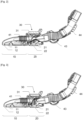
- FIG 2 represents a cross-sectional view of the vacuum cleaner nozzle of the figure 1 , with the inspection hatch 30 which comprises a valve 31 in a first position (or low position), to allow suction only through the first suction mouth 12.
- FIG 3 represents a cross-sectional view of the vacuum cleaner nozzle of the figure 1 , with the valve 31 in a second position (or high position), to allow suction only through the second suction mouth 22.
- the vacuum cleaner nozzle according to the present invention therefore comprises two suction inlets 12 and 22, and the valve 31 makes it possible to modulate and direct the suction flow from one suction inlet to the other, which provides effective cleaning of the floors.
- the valve 31 is typically rotatably mounted on the inspection hatch 30, and its position can vary according to the distribution setting desired by the user. However, due to the waste that passes through and the geometry of the area between the first suction inlet 12 and the second suction inlet 22, this waste can accumulate, become blocked or get caught on the mechanism of the valve 31 or nearby.
- the removal of the inspection hatch 30 leaves free access to the internal conduits of the vacuum cleaner nozzle, in particular at the level of the area between the first suction mouth 12 and the second suction mouth 22, so that the user can access them, all the more so since the valve 31 being embedded on the inspection hatch 30, it does not hinder access.
- the inspection hatch 30, located between the first suction mouth 12 and the second suction mouth 22, allows free access to this area, precisely where there may be accumulations or blockages of waste (due to the geometry and complex flows which take place there), so that maintenance and servicing are greatly facilitated.
- FIG. 5 shows an enlarged perspective view of the inspection hatch 30 removed from the vacuum cleaner nozzle.
- the inspection hatch 30 comprises a control wheel 32 with a thin wall to be pinched between the thumb and index finger of the user, who can then rotate the control wheel 32 about an axis of rotation 32A.
- Two lugs 34 are integral with the control wheel 32 and can engage with hooks 35 of the vacuum cleaner nozzle, visible figure 4 .
- FIG 4 also shows a peripheral seal 33 (an elastomer O-ring) which helps to eliminate air leaks when the inspection hatch 30 is mounted on the vacuum cleaner nozzle.
- a slope or chamfer may be provided on the hooks 35, or a variable thickness on the lugs 34, in order to compress the peripheral seal 33, when locking the inspection hatch 30.
- a cam track is provided on the locking means to compress the sealing means.
- the figure 5 also shows the axis of rotation 31A of the valve 31, not visible in this figure 5 .
- the inspection hatch also includes a mechanism for controlling the position of the valve 31, not shown.
- the nozzle comprises a first sole and a second separate sole, but there could be only one sole, with two suction mouths, or only a Y connection between two suction channels.
Landscapes
- Engineering & Computer Science (AREA)
- Mechanical Engineering (AREA)
- Nozzles For Electric Vacuum Cleaners (AREA)
Applications Claiming Priority (2)
| Application Number | Priority Date | Filing Date | Title |
|---|---|---|---|
| FR1873107A FR3089779B1 (fr) | 2018-12-17 | 2018-12-17 | Suceur d’aspirateur |
| EP19215804.6A EP3669730B1 (de) | 2018-12-17 | 2019-12-12 | Saugdüse eines saugers |
Related Parent Applications (2)
| Application Number | Title | Priority Date | Filing Date |
|---|---|---|---|
| EP19215804.6A Division EP3669730B1 (de) | 2018-12-17 | 2019-12-12 | Saugdüse eines saugers |
| EP19215804.6A Division-Into EP3669730B1 (de) | 2018-12-17 | 2019-12-12 | Saugdüse eines saugers |
Publications (2)
| Publication Number | Publication Date |
|---|---|
| EP4420583A2 true EP4420583A2 (de) | 2024-08-28 |
| EP4420583A3 EP4420583A3 (de) | 2025-04-30 |
Family
ID=66530234
Family Applications (2)
| Application Number | Title | Priority Date | Filing Date |
|---|---|---|---|
| EP24188490.7A Withdrawn EP4420583A3 (de) | 2018-12-17 | 2019-12-12 | Staubsaugermundstück |
| EP19215804.6A Active EP3669730B1 (de) | 2018-12-17 | 2019-12-12 | Saugdüse eines saugers |
Family Applications After (1)
| Application Number | Title | Priority Date | Filing Date |
|---|---|---|---|
| EP19215804.6A Active EP3669730B1 (de) | 2018-12-17 | 2019-12-12 | Saugdüse eines saugers |
Country Status (3)
| Country | Link |
|---|---|
| EP (2) | EP4420583A3 (de) |
| CN (1) | CN111317399A (de) |
| FR (1) | FR3089779B1 (de) |
Families Citing this family (1)
| Publication number | Priority date | Publication date | Assignee | Title |
|---|---|---|---|---|
| FR3113822B1 (fr) * | 2020-09-04 | 2022-09-16 | Seb Sa | Suceur d’aspirateur combinant une premiere tête d’aspiration et une deuxieme tête d’aspiration |
Citations (2)
| Publication number | Priority date | Publication date | Assignee | Title |
|---|---|---|---|---|
| EP0783865A2 (de) | 1996-01-11 | 1997-07-16 | Black & Decker Inc. | Staubsauger mit einer kombinierten Filter- und Sammelvorrichtung |
| EP1021120A1 (de) | 1997-01-30 | 2000-07-26 | Notetry Limited | Staubsauger |
Family Cites Families (7)
| Publication number | Priority date | Publication date | Assignee | Title |
|---|---|---|---|---|
| FR2856265B1 (fr) * | 2003-06-20 | 2005-09-16 | Seb Sa | Suceur d'aspirateur |
| CN101991386B (zh) * | 2009-08-24 | 2014-02-05 | 乐金电子(天津)电器有限公司 | 一种吸尘器用吹风式刷头 |
| GB2504676B (en) | 2012-08-03 | 2014-11-26 | Dyson Technology Ltd | A floor tool for a vacuum cleaning appliance |
| FR2999410B1 (fr) * | 2012-12-19 | 2015-11-06 | Seb Sa | Trappe pour suceur d'aspirateur |
| FR3011455B1 (fr) * | 2013-10-08 | 2015-12-18 | Seb Sa | Nettoyeur vapeur |
| US9173533B1 (en) * | 2014-06-25 | 2015-11-03 | Emerson Electric Co. | Upright vacuum cleaner |
| GB201706357D0 (en) * | 2017-04-21 | 2017-06-07 | Grey Tech Ltd | Bagged vacuum cleaner |
-
2018
- 2018-12-17 FR FR1873107A patent/FR3089779B1/fr active Active
-
2019
- 2019-12-12 EP EP24188490.7A patent/EP4420583A3/de not_active Withdrawn
- 2019-12-12 EP EP19215804.6A patent/EP3669730B1/de active Active
- 2019-12-16 CN CN201911291277.3A patent/CN111317399A/zh active Pending
Patent Citations (2)
| Publication number | Priority date | Publication date | Assignee | Title |
|---|---|---|---|---|
| EP0783865A2 (de) | 1996-01-11 | 1997-07-16 | Black & Decker Inc. | Staubsauger mit einer kombinierten Filter- und Sammelvorrichtung |
| EP1021120A1 (de) | 1997-01-30 | 2000-07-26 | Notetry Limited | Staubsauger |
Also Published As
| Publication number | Publication date |
|---|---|
| FR3089779B1 (fr) | 2020-11-20 |
| EP4420583A3 (de) | 2025-04-30 |
| CN111317399A (zh) | 2020-06-23 |
| EP3669730B1 (de) | 2024-08-21 |
| EP3669730A1 (de) | 2020-06-24 |
| FR3089779A1 (fr) | 2020-06-19 |
Similar Documents
| Publication | Publication Date | Title |
|---|---|---|
| EP2934267B1 (de) | Sauger-falltür eines staubsaugers | |
| EP2760325B1 (de) | Staubsaugerdüse | |
| EP1173085B1 (de) | Staubsaugermundstück mit abstreifleiste | |
| GB2530932A (en) | Vacuum cleaner head | |
| EP4241640B1 (de) | Tragbarer staubsauger, der mit einem abnehmbaren filter ausgestattet ist | |
| US8133052B1 (en) | Dental mirror with mirror-cleaning suction | |
| CN105228498B (zh) | 硬表面清洁装置 | |
| EP3669730B1 (de) | Saugdüse eines saugers | |
| EP3530168B1 (de) | Saugdüse eines saugers, bei der ein erster saugkopf mit einem zweiten kombiniert ist, die untereinander durch ein gelenksystem verbunden sind | |
| EP3556273B1 (de) | Saugdüse eines saugers, die mit einem hauptsaugkanal und einem sekundären saugkanal ausgestattet ist | |
| EP3202299B1 (de) | Dampfreiniger | |
| FR2968186A1 (fr) | Crosse pour aspirateur | |
| EP3530169B2 (de) | Saugdüse eines saugers, bei der ein erster saugkopf mit einem zweiten kombiniert ist | |
| EP3158908A1 (de) | Dampfreiniger | |
| EP3838093A1 (de) | Reinigungskopf, der mit einem feuchten reinigungselement ausgestattet ist | |
| WO2020070217A1 (fr) | Balai de nettoyage de sol a fonction electrique | |
| EP3838092A1 (de) | Reinigungskopf, der mit einem feuchten reinigungselement ausgestattet ist | |
| EP4039149B1 (de) | Ansaugeinheit mit einer vorrichtung zum trennen und sammeln von teilweise kugelförmigen abfällen | |
| EP4497361B1 (de) | Staubsaugerkanal mit gelenkvorrichtung | |
| EP4311464A1 (de) | Saugkopf mit einer sohle mit gekrümmter vordergleitfläche | |
| EP4039148A1 (de) | Schlittenartige ansaugeinheit, die mit einer zyklonabscheidevorrichtung ausgestattet ist | |
| WO2022269209A1 (fr) | Tête de nettoyage équipée d'un dispositif de nettoyage humide | |
| FR2948005A1 (fr) | Dispositif de fixation d'un tube d'aspiration pour appareil de recuperation des dechets | |
| EP0673635A1 (de) | Massagegerät für die Haut | |
| WO2018197340A1 (fr) | Embout d'extremite destine a un balai d'essuyage |
Legal Events
| Date | Code | Title | Description |
|---|---|---|---|
| PUAI | Public reference made under article 153(3) epc to a published international application that has entered the european phase |
Free format text: ORIGINAL CODE: 0009012 |
|
| STAA | Information on the status of an ep patent application or granted ep patent |
Free format text: STATUS: THE APPLICATION HAS BEEN PUBLISHED |
|
| AC | Divisional application: reference to earlier application |
Ref document number: 3669730 Country of ref document: EP Kind code of ref document: P |
|
| AK | Designated contracting states |
Kind code of ref document: A2 Designated state(s): AL AT BE BG CH CY CZ DE DK EE ES FI FR GB GR HR HU IE IS IT LI LT LU LV MC MK MT NL NO PL PT RO RS SE SI SK SM TR |
|
| REG | Reference to a national code |
Ref country code: DE Ref legal event code: R079 Free format text: PREVIOUS MAIN CLASS: A47L0009020000 Ipc: A47L0009000000 |
|
| PUAL | Search report despatched |
Free format text: ORIGINAL CODE: 0009013 |
|
| AK | Designated contracting states |
Kind code of ref document: A3 Designated state(s): AL AT BE BG CH CY CZ DE DK EE ES FI FR GB GR HR HU IE IS IT LI LT LU LV MC MK MT NL NO PL PT RO RS SE SI SK SM TR |
|
| RIC1 | Information provided on ipc code assigned before grant |
Ipc: A47L 9/02 20060101ALI20250325BHEP Ipc: A47L 9/00 20060101AFI20250325BHEP |
|
| STAA | Information on the status of an ep patent application or granted ep patent |
Free format text: STATUS: THE APPLICATION IS DEEMED TO BE WITHDRAWN |
|
| 18D | Application deemed to be withdrawn |
Effective date: 20251031 |