EP4419830B1 - Brennstoffzellensystem, gastankvorrichtung und absperreinrichtung für eine gastankvorrichtung - Google Patents
Brennstoffzellensystem, gastankvorrichtung und absperreinrichtung für eine gastankvorrichtung Download PDFInfo
- Publication number
- EP4419830B1 EP4419830B1 EP22797675.0A EP22797675A EP4419830B1 EP 4419830 B1 EP4419830 B1 EP 4419830B1 EP 22797675 A EP22797675 A EP 22797675A EP 4419830 B1 EP4419830 B1 EP 4419830B1
- Authority
- EP
- European Patent Office
- Prior art keywords
- main valve
- chamber
- opening
- shut
- servo
- Prior art date
- Legal status (The legal status is an assumption and is not a legal conclusion. Google has not performed a legal analysis and makes no representation as to the accuracy of the status listed.)
- Active
Links
Images

Classifications
-
- H—ELECTRICITY
- H01—ELECTRIC ELEMENTS
- H01M—PROCESSES OR MEANS, e.g. BATTERIES, FOR THE DIRECT CONVERSION OF CHEMICAL ENERGY INTO ELECTRICAL ENERGY
- H01M8/00—Fuel cells; Manufacture thereof
- H01M8/04—Auxiliary arrangements, e.g. for control of pressure or for circulation of fluids
- H01M8/04082—Arrangements for control of reactant parameters, e.g. pressure or concentration
- H01M8/04201—Reactant storage and supply, e.g. means for feeding, pipes
-
- F—MECHANICAL ENGINEERING; LIGHTING; HEATING; WEAPONS; BLASTING
- F16—ENGINEERING ELEMENTS AND UNITS; GENERAL MEASURES FOR PRODUCING AND MAINTAINING EFFECTIVE FUNCTIONING OF MACHINES OR INSTALLATIONS; THERMAL INSULATION IN GENERAL
- F16K—VALVES; TAPS; COCKS; ACTUATING-FLOATS; DEVICES FOR VENTING OR AERATING
- F16K1/00—Lift valves or globe valves, i.e. cut-off apparatus with closure members having at least a component of their opening and closing motion perpendicular to the closing faces
- F16K1/30—Lift valves or globe valves, i.e. cut-off apparatus with closure members having at least a component of their opening and closing motion perpendicular to the closing faces specially adapted for pressure containers
-
- F—MECHANICAL ENGINEERING; LIGHTING; HEATING; WEAPONS; BLASTING
- F16—ENGINEERING ELEMENTS AND UNITS; GENERAL MEASURES FOR PRODUCING AND MAINTAINING EFFECTIVE FUNCTIONING OF MACHINES OR INSTALLATIONS; THERMAL INSULATION IN GENERAL
- F16K—VALVES; TAPS; COCKS; ACTUATING-FLOATS; DEVICES FOR VENTING OR AERATING
- F16K31/00—Actuating devices; Operating means; Releasing devices
- F16K31/02—Actuating devices; Operating means; Releasing devices electric; magnetic
- F16K31/06—Actuating devices; Operating means; Releasing devices electric; magnetic using a magnet, e.g. diaphragm valves, cutting off by means of a liquid
- F16K31/0644—One-way valve
- F16K31/0655—Lift valves
-
- F—MECHANICAL ENGINEERING; LIGHTING; HEATING; WEAPONS; BLASTING
- F16—ENGINEERING ELEMENTS AND UNITS; GENERAL MEASURES FOR PRODUCING AND MAINTAINING EFFECTIVE FUNCTIONING OF MACHINES OR INSTALLATIONS; THERMAL INSULATION IN GENERAL
- F16K—VALVES; TAPS; COCKS; ACTUATING-FLOATS; DEVICES FOR VENTING OR AERATING
- F16K31/00—Actuating devices; Operating means; Releasing devices
- F16K31/12—Actuating devices; Operating means; Releasing devices actuated by fluid
- F16K31/122—Actuating devices; Operating means; Releasing devices actuated by fluid the fluid acting on a piston
- F16K31/124—Actuating devices; Operating means; Releasing devices actuated by fluid the fluid acting on a piston servo actuated
-
- F—MECHANICAL ENGINEERING; LIGHTING; HEATING; WEAPONS; BLASTING
- F16—ENGINEERING ELEMENTS AND UNITS; GENERAL MEASURES FOR PRODUCING AND MAINTAINING EFFECTIVE FUNCTIONING OF MACHINES OR INSTALLATIONS; THERMAL INSULATION IN GENERAL
- F16K—VALVES; TAPS; COCKS; ACTUATING-FLOATS; DEVICES FOR VENTING OR AERATING
- F16K31/00—Actuating devices; Operating means; Releasing devices
- F16K31/12—Actuating devices; Operating means; Releasing devices actuated by fluid
- F16K31/36—Actuating devices; Operating means; Releasing devices actuated by fluid in which fluid from the circuit is constantly supplied to the fluid motor
- F16K31/40—Actuating devices; Operating means; Releasing devices actuated by fluid in which fluid from the circuit is constantly supplied to the fluid motor with electrically-actuated member in the discharge of the motor
- F16K31/406—Actuating devices; Operating means; Releasing devices actuated by fluid in which fluid from the circuit is constantly supplied to the fluid motor with electrically-actuated member in the discharge of the motor acting on a piston
-
- F—MECHANICAL ENGINEERING; LIGHTING; HEATING; WEAPONS; BLASTING
- F17—STORING OR DISTRIBUTING GASES OR LIQUIDS
- F17C—VESSELS FOR CONTAINING OR STORING COMPRESSED, LIQUEFIED OR SOLIDIFIED GASES; FIXED-CAPACITY GAS-HOLDERS; FILLING VESSELS WITH, OR DISCHARGING FROM VESSELS, COMPRESSED, LIQUEFIED, OR SOLIDIFIED GASES
- F17C13/00—Details of vessels or of the filling or discharging of vessels
- F17C13/04—Arrangement or mounting of valves
-
- F—MECHANICAL ENGINEERING; LIGHTING; HEATING; WEAPONS; BLASTING
- F17—STORING OR DISTRIBUTING GASES OR LIQUIDS
- F17C—VESSELS FOR CONTAINING OR STORING COMPRESSED, LIQUEFIED OR SOLIDIFIED GASES; FIXED-CAPACITY GAS-HOLDERS; FILLING VESSELS WITH, OR DISCHARGING FROM VESSELS, COMPRESSED, LIQUEFIED, OR SOLIDIFIED GASES
- F17C2201/00—Vessel construction, in particular geometry, arrangement or size
- F17C2201/01—Shape
- F17C2201/0104—Shape cylindrical
- F17C2201/0109—Shape cylindrical with exteriorly curved end-piece
-
- F—MECHANICAL ENGINEERING; LIGHTING; HEATING; WEAPONS; BLASTING
- F17—STORING OR DISTRIBUTING GASES OR LIQUIDS
- F17C—VESSELS FOR CONTAINING OR STORING COMPRESSED, LIQUEFIED OR SOLIDIFIED GASES; FIXED-CAPACITY GAS-HOLDERS; FILLING VESSELS WITH, OR DISCHARGING FROM VESSELS, COMPRESSED, LIQUEFIED, OR SOLIDIFIED GASES
- F17C2201/00—Vessel construction, in particular geometry, arrangement or size
- F17C2201/05—Size
- F17C2201/056—Small (<1 m3)
-
- F—MECHANICAL ENGINEERING; LIGHTING; HEATING; WEAPONS; BLASTING
- F17—STORING OR DISTRIBUTING GASES OR LIQUIDS
- F17C—VESSELS FOR CONTAINING OR STORING COMPRESSED, LIQUEFIED OR SOLIDIFIED GASES; FIXED-CAPACITY GAS-HOLDERS; FILLING VESSELS WITH, OR DISCHARGING FROM VESSELS, COMPRESSED, LIQUEFIED, OR SOLIDIFIED GASES
- F17C2205/00—Vessel construction, in particular mounting arrangements, attachments or identifications means
- F17C2205/03—Fluid connections, filters, valves, closure means or other attachments
- F17C2205/0302—Fittings, valves, filters, or components in connection with the gas storage device
- F17C2205/0323—Valves
- F17C2205/0326—Valves electrically actuated
-
- F—MECHANICAL ENGINEERING; LIGHTING; HEATING; WEAPONS; BLASTING
- F17—STORING OR DISTRIBUTING GASES OR LIQUIDS
- F17C—VESSELS FOR CONTAINING OR STORING COMPRESSED, LIQUEFIED OR SOLIDIFIED GASES; FIXED-CAPACITY GAS-HOLDERS; FILLING VESSELS WITH, OR DISCHARGING FROM VESSELS, COMPRESSED, LIQUEFIED, OR SOLIDIFIED GASES
- F17C2205/00—Vessel construction, in particular mounting arrangements, attachments or identifications means
- F17C2205/03—Fluid connections, filters, valves, closure means or other attachments
- F17C2205/0302—Fittings, valves, filters, or components in connection with the gas storage device
- F17C2205/0338—Pressure regulators
-
- F—MECHANICAL ENGINEERING; LIGHTING; HEATING; WEAPONS; BLASTING
- F17—STORING OR DISTRIBUTING GASES OR LIQUIDS
- F17C—VESSELS FOR CONTAINING OR STORING COMPRESSED, LIQUEFIED OR SOLIDIFIED GASES; FIXED-CAPACITY GAS-HOLDERS; FILLING VESSELS WITH, OR DISCHARGING FROM VESSELS, COMPRESSED, LIQUEFIED, OR SOLIDIFIED GASES
- F17C2205/00—Vessel construction, in particular mounting arrangements, attachments or identifications means
- F17C2205/03—Fluid connections, filters, valves, closure means or other attachments
- F17C2205/0302—Fittings, valves, filters, or components in connection with the gas storage device
- F17C2205/0382—Constructional details of valves, regulators
-
- F—MECHANICAL ENGINEERING; LIGHTING; HEATING; WEAPONS; BLASTING
- F17—STORING OR DISTRIBUTING GASES OR LIQUIDS
- F17C—VESSELS FOR CONTAINING OR STORING COMPRESSED, LIQUEFIED OR SOLIDIFIED GASES; FIXED-CAPACITY GAS-HOLDERS; FILLING VESSELS WITH, OR DISCHARGING FROM VESSELS, COMPRESSED, LIQUEFIED, OR SOLIDIFIED GASES
- F17C2205/00—Vessel construction, in particular mounting arrangements, attachments or identifications means
- F17C2205/03—Fluid connections, filters, valves, closure means or other attachments
- F17C2205/0302—Fittings, valves, filters, or components in connection with the gas storage device
- F17C2205/0382—Constructional details of valves, regulators
- F17C2205/0385—Constructional details of valves, regulators in blocks or units
-
- F—MECHANICAL ENGINEERING; LIGHTING; HEATING; WEAPONS; BLASTING
- F17—STORING OR DISTRIBUTING GASES OR LIQUIDS
- F17C—VESSELS FOR CONTAINING OR STORING COMPRESSED, LIQUEFIED OR SOLIDIFIED GASES; FIXED-CAPACITY GAS-HOLDERS; FILLING VESSELS WITH, OR DISCHARGING FROM VESSELS, COMPRESSED, LIQUEFIED, OR SOLIDIFIED GASES
- F17C2221/00—Handled fluid, in particular type of fluid
- F17C2221/01—Pure fluids
- F17C2221/012—Hydrogen
-
- F—MECHANICAL ENGINEERING; LIGHTING; HEATING; WEAPONS; BLASTING
- F17—STORING OR DISTRIBUTING GASES OR LIQUIDS
- F17C—VESSELS FOR CONTAINING OR STORING COMPRESSED, LIQUEFIED OR SOLIDIFIED GASES; FIXED-CAPACITY GAS-HOLDERS; FILLING VESSELS WITH, OR DISCHARGING FROM VESSELS, COMPRESSED, LIQUEFIED, OR SOLIDIFIED GASES
- F17C2223/00—Handled fluid before transfer, i.e. state of fluid when stored in the vessel or before transfer from the vessel
- F17C2223/01—Handled fluid before transfer, i.e. state of fluid when stored in the vessel or before transfer from the vessel characterised by the phase
- F17C2223/0107—Single phase
- F17C2223/0123—Single phase gaseous, e.g. CNG, GNC
-
- F—MECHANICAL ENGINEERING; LIGHTING; HEATING; WEAPONS; BLASTING
- F17—STORING OR DISTRIBUTING GASES OR LIQUIDS
- F17C—VESSELS FOR CONTAINING OR STORING COMPRESSED, LIQUEFIED OR SOLIDIFIED GASES; FIXED-CAPACITY GAS-HOLDERS; FILLING VESSELS WITH, OR DISCHARGING FROM VESSELS, COMPRESSED, LIQUEFIED, OR SOLIDIFIED GASES
- F17C2223/00—Handled fluid before transfer, i.e. state of fluid when stored in the vessel or before transfer from the vessel
- F17C2223/03—Handled fluid before transfer, i.e. state of fluid when stored in the vessel or before transfer from the vessel characterised by the pressure level
- F17C2223/036—Very high pressure (>80 bar)
-
- F—MECHANICAL ENGINEERING; LIGHTING; HEATING; WEAPONS; BLASTING
- F17—STORING OR DISTRIBUTING GASES OR LIQUIDS
- F17C—VESSELS FOR CONTAINING OR STORING COMPRESSED, LIQUEFIED OR SOLIDIFIED GASES; FIXED-CAPACITY GAS-HOLDERS; FILLING VESSELS WITH, OR DISCHARGING FROM VESSELS, COMPRESSED, LIQUEFIED, OR SOLIDIFIED GASES
- F17C2260/00—Purposes of gas storage and gas handling
- F17C2260/02—Improving properties related to fluid or fluid transfer
-
- F—MECHANICAL ENGINEERING; LIGHTING; HEATING; WEAPONS; BLASTING
- F17—STORING OR DISTRIBUTING GASES OR LIQUIDS
- F17C—VESSELS FOR CONTAINING OR STORING COMPRESSED, LIQUEFIED OR SOLIDIFIED GASES; FIXED-CAPACITY GAS-HOLDERS; FILLING VESSELS WITH, OR DISCHARGING FROM VESSELS, COMPRESSED, LIQUEFIED, OR SOLIDIFIED GASES
- F17C2265/00—Effects achieved by gas storage or gas handling
- F17C2265/06—Fluid distribution
- F17C2265/066—Fluid distribution for feeding engines for propulsion
-
- F—MECHANICAL ENGINEERING; LIGHTING; HEATING; WEAPONS; BLASTING
- F17—STORING OR DISTRIBUTING GASES OR LIQUIDS
- F17C—VESSELS FOR CONTAINING OR STORING COMPRESSED, LIQUEFIED OR SOLIDIFIED GASES; FIXED-CAPACITY GAS-HOLDERS; FILLING VESSELS WITH, OR DISCHARGING FROM VESSELS, COMPRESSED, LIQUEFIED, OR SOLIDIFIED GASES
- F17C2270/00—Applications
- F17C2270/01—Applications for fluid transport or storage
- F17C2270/0165—Applications for fluid transport or storage on the road
- F17C2270/0168—Applications for fluid transport or storage on the road by vehicles
-
- Y—GENERAL TAGGING OF NEW TECHNOLOGICAL DEVELOPMENTS; GENERAL TAGGING OF CROSS-SECTIONAL TECHNOLOGIES SPANNING OVER SEVERAL SECTIONS OF THE IPC; TECHNICAL SUBJECTS COVERED BY FORMER USPC CROSS-REFERENCE ART COLLECTIONS [XRACs] AND DIGESTS
- Y02—TECHNOLOGIES OR APPLICATIONS FOR MITIGATION OR ADAPTATION AGAINST CLIMATE CHANGE
- Y02E—REDUCTION OF GREENHOUSE GAS [GHG] EMISSIONS, RELATED TO ENERGY GENERATION, TRANSMISSION OR DISTRIBUTION
- Y02E60/00—Enabling technologies; Technologies with a potential or indirect contribution to GHG emissions mitigation
- Y02E60/30—Hydrogen technology
- Y02E60/50—Fuel cells
Definitions
- the present invention relates to a fuel cell system, a gas tank device, in particular for a fuel cell system, and a shut-off device for a gas tank device.
- Fuel cell systems typically comprise a fuel cell arrangement, e.g. in the form of a stack with a plurality of fuel cells connected electrically in series, to which gaseous fuel, e.g. hydrogen, is supplied from a tank via a fuel supply line.
- gaseous fuel e.g. hydrogen
- the gaseous fuel in the tank is typically under high pressure, which can be up to 700 bar or more, for example.
- the tank thus forms a high-pressure reservoir.
- the fuel is normally supplied to the fuel cell arrangement at a lower pressure, e.g. with a pressure in the range between 2 bar and 20 bar.
- the fuel supply line can be connected to the tank, for example, via a pressure regulating device in which the pressure of the fuel is reduced.
- the line between the tank and the pressure regulating device is typically designed as a high-pressure line and is referred to below as the supply line, since it is via this that the fuel cell system is supplied with fuel.
- the tank is typically provided with a shut-off valve to prevent fuel from escaping from the tank, e.g. when the fuel cell arrangement is taken out of service or in the event of a defect.
- Shut-off valves for high-pressure gas tanks are usually designed as normally closed solenoid valves.
- a valve needle is spring-loaded against a sealing seat and can be lifted from the sealing seat by a magnetic force generated by a coil, counteracting the spring's preload. Due to the high pressure in the tank, high opening forces may be required, depending on the valve design. This requires powerful coils and complicates valve miniaturization.
- the DE 10 2006 027 712 A1 discloses a shut-off valve for a hydrogen pressure tank, comprising a housing having a first valve seat and a second valve seat, and a valve stem movable by an electric coil, which valve stem carries spaced-apart first and second sealing elements on its outer circumference.
- the sealing elements are biased against the valve seats by a spring to seal an inlet from an outlet formed between the valve seats in the housing.
- the valve stem has a first opening, which forms a fluid connection between the inlet and a high-pressure side of the first sealing element. As a result, a closing force is exerted on the first sealing element due to the pressure applied at the inlet.
- valve stem has a through-bore, which connects a secondary chamber located on a low-pressure side of the second sealing element to the inlet.
- an opening force is exerted on the second sealing element, which acts oppositely to the closing force acting on the first sealing body.
- the aim of this design is to reduce the force acting on the valve stem or the sealing elements due to the pressure difference in order to reduce the opening force generated by the electrical coil to open the valve.
- the JP 2016 156485 A discloses a valve device comprising: a housing having a primary passage, a secondary passage, and a valve element space between the primary passage and the secondary passage, the primary passage and the secondary passage forming a main passage.
- a vehicle-mounted ultra-high-pressure hydrogen storage cylinder combination valve is shown, which includes a valve body.
- the DE 10 2018 221 600 A1 discloses a method for operating a tank device for storing compressed fluids with a tank, a valve device, a supply line, a flow element arranged in the supply line and a control unit.
- DE 10 2018 215 380 A1 shows a valve device for a gaseous medium, in particular hydrogen, with a valve housing and a first magnet armature arranged therein, which can be moved along a longitudinal axis.
- shut-off device for a gas tank device having the features of claim 1, a gas tank device having the features of claim 8 and a fuel cell system having the features of claim 10 are provided.
- a shut-off device for a gas tank device comprises a first connection for connection to a high-pressure tank, a second connection for connection to a supply line, a main valve chamber having a first opening fluidically connected to the first connection, a second opening fluidically connected to the second connection, and a first control opening, a main valve designed as a switchable solenoid valve with a main valve needle arranged in the main valve chamber, which is movable between a closed position, in which it rests against a main valve seat surrounding the second opening in order to seal the second opening from the first opening, and an open position, in which it is lifted from the main valve seat.
- the main valve needle divides the main valve chamber into an outlet chamber, into which the first and second openings open, and a control chamber into which the first control opening opens and which is fluidically connected to the outlet chamber.
- the shut-off device further comprises a servo valve chamber spatially separated from the main valve chamber, which has a second control opening fluidically connected to the first control opening and a servo opening fluidically connected to the second connection, and a servo valve designed as a switchable solenoid valve with a servo valve needle arranged in the servo valve chamber, which servo valve needle can be moved between a closed position in which it rests against a servo valve seat surrounding the servo opening in order to seal the servo opening from the second control opening, and an open position in which it is lifted off the servo valve seat.
- a gas tank device in particular for a fuel cell system, is provided.
- the gas tank device according to the invention comprises a high-pressure gas tank for holding gas, such as hydrogen, and a shut-off device according to the first aspect of the invention, wherein the first connection of the shut-off device is connected to an outlet opening of the high-pressure gas tank.
- a fuel cell system comprises a fuel cell arrangement having at least one fuel cell, a fuel inlet for supplying gaseous fuel, an oxidizing gas inlet for supplying oxidizing gas and a product outlet for discharging reaction products, a fuel supply line connected to the fuel inlet and a gas tank device according to the second aspect of the invention, wherein the second connection of the shut-off device is connected to the fuel supply line.
- One idea underlying the invention is to realize a shut-off device in which a main valve and a servo valve are each arranged spatially separated from one another.
- a main valve needle is arranged in a first chamber or main valve chamber and is movable between an open and a closed position by means of a first coil
- a servo valve needle is arranged in a second chamber or servo valve chamber spatially arranged from the main valve chamber and fluidically connected to it and is movable between an open and a closed position by means of its own second coil.
- the main valve needle is displaceably guided in the first chamber and divides it into a control chamber, which is fluidically connected to the second chamber, and a Outlet chamber having a first opening connected to a high-pressure port or first port and a second opening connected to a supply port or second port, which is covered or closed by the main valve needle in the closed position.
- the second chamber is also fluidically connected to the supply port via a servo opening, which is covered or closed by the servo valve needle in its closed position.
- One advantage of the invention is that the servo valve and main valve, or rather their valve needles, are housed in spatially separate chambers and are movable by their own coils. This facilitates a space-optimized arrangement of the servo valve and main valve.
- a fluidic connection can be established between the second connection or the supply connection, which is provided for connection to a low-pressure reservoir such as the fuel supply line, and the control chamber of the main valve chamber with a relatively low opening force. Since the control chamber is fluidically connected via the outlet chamber to the first connection or the high-pressure connection, which is provided for connection to a high-pressure reservoir such as the gas tank, pressure equalization takes place between the second connection and the control chamber.
- the main valve chamber and the servo valve chamber can be formed in a common housing. Due to the spatially separate arrangement of the main and servo valve chambers in the housing, the valve needles can be oriented in any desired manner relative to one another, which further facilitates a space-optimized arrangement or design.
- first control opening and the second control opening are connected by a connecting bore.
- the fluidic connection between the outlet chamber and the control chamber of the main valve chamber can be dimensioned such that, when the servo valve is open and the main valve is closed, it acts as a throttle for fluid flow from the outlet chamber into the control chamber. This slows down the pressure equalization between the outlet chamber and the control chamber, thereby further increasing the opening force acting on the main valve needle.
- the outlet chamber and the control chamber of the main valve chamber are fluidically connected to one another through a bore in the main valve needle.
- the outlet chamber and the control chamber of the main valve chamber are fluidically connected to one another through a gap formed between an outer circumference of the main valve needle and a wall surrounding the main valve chamber.
- the width of the gap can be defined, for example, by the fit provided between the wall and the main valve needle, e.g., a clearance fit.
- the gap can also be formed only locally, e.g., by forming a groove in the wall and/or outer circumference of the valve needle. This creates structurally simple and cost-effectively manufactured connecting lines between the control chamber and the outlet chamber.
- the main valve is designed as a normally closed solenoid valve and has a spring which biases the main valve needle into the closed position.
- the servo valve is designed as a normally closed solenoid valve and has a spring which biases the servo valve needle into the closed position.
- the shut-off device is accommodated in the outlet opening of the high-pressure gas tank.
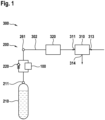
- FIG. 1 A fuel cell system 300 is shown schematically by way of example. As in Fig. 1 Shown schematically, the fuel cell system 300 includes a fuel cell assembly 310, a fuel supply line 302, an optional pressure control device 320, and a gas tank device 200.
- the fuel cell assembly 310 is in Fig. 1 shown only as a block and has at least one fuel cell (not shown), a fuel inlet 311, an oxidizing gas inlet 313 and a product outlet 314.
- the fuel cell arrangement can, for example, have a plurality of fuel cells connected electrically in series, e.g. in the form of a so-called stack.
- Each fuel cell has an anode, a cathode and an electrolyte layer arranged between the anode and cathode, e.g. in the form of a membrane.
- Gaseous fuel e.g. hydrogen
- oxidizing gas e.g.
- oxygen-containing ambient air can be supplied to the cathodes of the fuel cell(s) via the oxidizing gas inlet 213.
- the reaction products can be removed from the cathode via the product outlet 314.
- the at least one fuel cell is thus designed to convert the chemical energy stored in the fuel together with oxidizing gas directly into electrical energy.
- the gas tank device 200 has a high-pressure gas tank 210 and a shut-off device 100.
- the high-pressure gas tank 210 hereinafter referred to simply as the tank for reasons of clarity, is designed to accommodate
- the tank 210 can be designed, for example, as a substantially cylindrical tank.
- An outlet opening 211 of the tank 210 can be arranged, for example, at an axial end of the tank 210.
- the shut-off device 100 is in Fig. 1 shown only symbolically and will be explained in more detail below.
- the shut-off device 100 is connected to the outlet opening 211 of the tank 210 and a low-pressure connection 261 of the gas tank device 200.
- a check valve 220 can be connected in parallel to the shut-off device 100, as shown in Fig. 1 shown by way of example.
- the fuel supply line 302 connects the low-pressure port 261 of the gas tank device 200 to the fuel inlet 311 of the fuel cell assembly 310.
- the optional pressure control device 320 is arranged between the low-pressure port 261 and the fuel inlet 311 in the fuel supply line 302 and is configured to reduce the pressure of the gas flowing out of the tank 210 and/or to vary the flow rate.
- the pressure control device 320 can comprise a flow-controllable throttle valve.
- Fig. 2 shows schematically and by way of example a shut-off device 100 as used in the gas tank device 200 in Fig. 1 can be installed.
- the shut-off device 100 has a first connection 11, a second connection 12, a main valve chamber 2, a main valve 3, a servo valve chamber 4 and a servo valve 5.
- the main valve chamber 2 and the servo valve chamber 4 are arranged spatially separated from each other.
- the chambers 2, 4 each define a cavity, which is delimited, for example, by walls 20, 40.
- the main valve chamber 2 and the servo valve chamber 4 can be formed in a common housing 1.
- the first connection 11 is provided for connection to the high-pressure tank 210 and can be designed, for example, as an opening or as a connection piece on the housing 1.
- the second connection 12 is provided for connection to the supply line or the fuel supply line 302 and can also be designed as an opening or as a connection piece on the housing 1.
- the main valve chamber 2 has a first opening 21, a second opening 22 and a first control opening 23.
- the first and second openings 21, 22 can each be formed in a first end region of the main valve chamber 2.
- the first opening 21 can be formed on a peripheral wall and the second opening 22 in a first end wall extending transversely to the peripheral wall, as shown in Fig. 2 is shown by way of example.
- the first control opening 23 can be formed in particular in a second end region of the main valve chamber 2, e.g. in a second end wall opposite the first end wall, as in Fig. 2 shown.
- the first opening 21 is fluidically connected to the first connection 11, e.g. via a bore or line 14.
- the second opening 22 is fluidically connected to the second connection 12, e.g. via a bore or line 15, as shown in Fig. 2 is shown as an example.
- the servo valve chamber 4 has a second control opening 41 and a servo opening 42.
- the servo opening 42 can be formed, for example, in an end wall of the servo valve chamber 4, and the second control opening 41 can be formed, for example, in a peripheral wall 40 extending transversely to the end wall, as shown in Fig. 2 is shown as an example.
- the first control opening 23 of the main valve chamber 2 and the second control opening of the servo valve chamber 4 are fluidically connected to each other, e.g. via a bore or line 13, as shown in Fig. 2 is shown schematically.
- the servo opening 42 is fluidically connected to the second connection 12, e.g. via a bore or line 16.
- the main valve 3 is designed as a normally closed solenoid valve 3 and has a main valve needle 30, a spring 31, and a coil 32.
- the main valve needle 30 is arranged in the main valve chamber 2 and is guided axially displaceably on its outer circumference 30a by the wall 20, in particular the peripheral wall.
- the main valve needle 30 may, for example, have a columnar or cylindrical main section 35 and a guide section 36 which projects radially from the main section 35 at a first axial end thereof.
- the end of the main section 35 has a sealing surface 35a, which can be conical, for example.
- the guide section 36 can, for example, have a cylindrical outer peripheral surface, which is guided along the wall 20.
- the main valve needle 30 divides the main valve chamber 2 into an outlet chamber 2A and a control chamber 2B.
- the guide section 36 can form a partition, as in Fig. 2 shown schematically.
- the first and second openings 21, 22 each open into the outlet chamber 2A.
- the first control opening 23 opens into the control chamber 2B.
- the control chamber 2B and the outlet chamber 2A are fluidically connected, e.g. by a bore 33 formed in the main valve needle 30, in particular the guide section 36, or by a gap 34 formed between the outer circumference 30a of the main valve needle 30, in particular the outer circumference of the guide section 36, and the wall 20.
- the gap 34 is in Fig. 2 Enlarged for clarity.
- the width of the gap 34 may be determined by the fit between the valve needle 30 and the bore diameter defined by the peripheral wall 20.
- the main valve needle 30 is movable between a closed position and an open position by means of the coil 32, which is arranged enclosing the main valve needle 30, e.g., outside the main valve chamber 2.
- the spring 31 biases the main valve needle 30 into the closed position and can be arranged, e.g., in the control chamber 2B, as shown in Fig. 2 is shown schematically.
- Fig. 2 shows the closed position of the main valve needle 30.
- the main valve needle 30, in particular its sealing surface 35a lies on a second Main valve seat surrounding opening 22 in order to seal the second opening 22 from the first opening 21.
- the main valve needle 30, in particular its sealing surface 35a is lifted from the main valve seat so that fluid can flow from the first connection 11 into the outlet chamber 2A and through the second opening 22 to the second connection 12.
- the servo valve 5 is also designed as a normally closed solenoid valve and has a servo valve needle 50, a spring 51 and a coil 352.
- the servo valve needle 50 is arranged in the servo valve chamber 4 and is axially
- the servo valve needle 50 can, for example, have a columnar or cylindrical main section 55 and a guide section 56, which protrudes radially from the main section 55 at a first axial end thereof.
- a second axial end of the main section 55 has a sealing surface 55a, which can, for example, be conical in shape.
- the guide section 56 can, for example, have a cylindrical outer peripheral surface, which is guided on the wall 40.
- the servo valve needle 50 is movable between a closed position and an open position by means of the coil 52, which is arranged enclosing the servo valve needle 50, e.g., outside the servo valve chamber 4.
- the spring 51 biases the servo valve needle 50 into the closed position and can be arranged, e.g., inside the servo valve chamber 4, as shown in Fig. 2 is shown schematically.
- Fig. 2 shows the closed position of the servo valve needle 50.
- the servo valve needle 50 In the closed position, the servo valve needle 50, in particular its sealing surface 55a, rests against a servo valve seat surrounding the servo opening 42 in order to seal the servo opening 42 from the second control opening 41. In the open position, the servo valve needle 50, in particular its sealing surface 55a, is lifted from the servo valve seat, so that a fluid exchange can take place through the servo valve chamber 4 via the second control opening 41 and the servo opening 42.
- the pressure applied to the first connection 11 is located in the outlet chamber 2A, the control chamber 2B and the servo valve chamber 4. Pressure.
- the main valve needle 3 has a first cross-sectional area A35 in a first end region facing the control chamber 2B.
- a second cross-sectional area A22 is defined by an area that is bounded by the main valve seat. As shown in Fig. 2 As shown schematically, the first cross-sectional area A35 is larger than the second cross-sectional area A22.
- the servo valve 5 is first opened, i.e., the coil 52 of the servo valve 5 is energized to lift the servo valve needle 50 from the servo valve seat.
- the control chamber 2B is thus fluidically connected to the pressure level of the second port 12 via the first and second control openings 23, 42 and the servo opening 42, which typically leads to a pressure reduction in the control chamber 2B.
- pressure equalization takes place between the control chamber 2B and the second port 12, which is why pressure equalization also occurs between the first control opening 23 and the second opening 22.
- the pressure force acting as a result of the different cross-sectional areas A35, A22 is increasingly reduced as a result of the pressure equalization.
- the fluidic connection between the outlet chamber 2A and the control chamber 2B of the main valve chamber 2, e.g. the gap 34 or the bore 33, can in particular be dimensioned such that when the servo valve 5 is open and the main valve 3 is closed, it acts as
- Throttle for fluid flow from the outlet chamber 2A into the control chamber 2B This further reduces the magnetic force generated by energizing the coil 32 to move the main valve needle 35 into the open position.
- the spatially separated arrangement of the main valve chamber 2 and the servo valve chamber 4 allows for the main and servo valves 3 and 5 to be accommodated in a space-optimized manner.
- the main valve needle 30 and the servo valve needle 50 can extend relative to each other in any desired manner, which significantly increases the flexibility of the arrangement.
- shut-off device 100 was described in connection with a gas tank device 200 for a fuel cell system 300, but is not limited thereto. In principle, the shut-off device 100 can be used in any gas line system.
Landscapes
- Engineering & Computer Science (AREA)
- General Engineering & Computer Science (AREA)
- Mechanical Engineering (AREA)
- Sustainable Energy (AREA)
- Manufacturing & Machinery (AREA)
- Sustainable Development (AREA)
- Life Sciences & Earth Sciences (AREA)
- Chemical & Material Sciences (AREA)
- Chemical Kinetics & Catalysis (AREA)
- Electrochemistry (AREA)
- General Chemical & Material Sciences (AREA)
- Magnetically Actuated Valves (AREA)
- Fuel Cell (AREA)
- Lift Valve (AREA)
- Safety Valves (AREA)
Description
- Die vorliegende Erfindung betrifft ein Brennstoffzellensystem, eine Gastankvorrichtung, insbesondere für ein Brennstoffzellensystem, und eine Absperreinrichtung für eine Gastankvorrichtung.
- Brennstoffzellensysteme umfassen üblicherweise eine Brennstoffzellenanordnung, z.B. in Form eines Stacks mit einer Vielzahl elektrisch in Reihe geschalteter Brennstoffzellen, welcher über eine Brennstoffzufuhrleitung gasförmiger Brennstoff, z.B. Wasserstoff, aus einem Tank zugeführt wird. Sowohl in stationären als auch in mobilen Anwendungen, wie z.B. in einem Fahrzeug, steht der gasförmige Brennstoff in dem Tank üblicherweise unter hohem Druck, welcher beispielsweise bis zu 700 bar oder mehr betragen kann. Der Tank bildet somit ein Hochdruckreservoir. Der Brennstoffzellenanordnung wird der Brennstoff normalerweise mit geringerem Druck zugeführt, z.B. mit einem Druck im Bereich zwischen 2 bar und 20 bar. Die Brennstoffzufuhrleitung kann beispielsweise durch eine Druckregelungsvorrichtung, in welcher der Druck des Brennstoffs reduziert wird, mit dem Tank verbunden sein. Die Leitung zwischen Tank und Druckregelungsvorrichtung ist üblicherweise als Hochdruckleitung ausgeführt und wird im Folgenden als Versorgungsleitung bezeichnet, da über diese das Brennstoffzellensystem mit Brennstoff versorgt wird. Der Tank ist üblicherweise mit einem Absperrventil versehen, um einen Brennstoffaustritt aus dem Tank abzusperren, z.B. wenn die Brennstoffzellenanordnung außer Betrieb genommen wird oder im Fall eines Defekts.
- Absperrventile für Hochdruckgastanks sind in der Regel als stromlos geschlossene Magnetventile konzipiert. Typischerweise wird eine Ventilnadel durch eine Feder gegen einen Dichtsitz vorgespannt und ist durch eine mittels einer Spule erzeugbare magnetische Kraft gegen die Vorspannkraft der Feder von dem Dichtsitz abhebbar. Aufgrund des hohen Drucks im Tank können je nach Bauart des Ventils hohe Öffnungskräfte erforderlich sein. Dies erfordert leistungsstarke Spulen und erschwert die Miniaturisierung des Ventils.
- Die
DE 10 2006 027 712 A1 offenbart ein Absperrventil für einen Wasserstoffdrucktank mit einem Gehäuse, welches einen ersten Ventilsitz und einen zweiten Ventilsitz aufweist, und einem durch eine elektrische Spule bewegbaren Ventilschaft, welcher an seinem Außenumfang beabstandete erste und zweite Dichtelemente trägt. In einer geschlossenen Stellung des Ventils sind die Dichtelemente durch eine Feder gegen die Ventilsitze vorgespannt, um einen Einlass gegenüber einem zwischen den Ventilsitzen im Gehäuse ausgebildeten Auslass abzudichten. Der Ventilschaft weist eine erste Öffnung auf, welche eine Fluidverbindung zwischen dem Einlass und einer Hochdruckseite des ersten Dichtelements ausbildet. Dadurch wird auf das erste Dichtelement eine Schließkraft infolge des am Einlass anliegenden Drucks ausgeübt. Ferner weist der Ventilschaft eine Durchgangsbohrung auf, die eine auf einer Niederdruckseite des zweiten Dichtelements gelegene Nebenkammer mit dem Einlass verbindet. Dadurch wird eine Öffnungskraft auf das zweite Dichtelement ausgeübt, die entgegengesetzt zu der auf den ersten Dichtkörper wirkenden Schließkraft wirkt. Ziel dieses Aufbaus ist es, eine durch die Druckdifferenz auf den Ventilschaft bzw. die Dichtelemente wirkende Kraft zu senken, um die durch die elektrische Spule zu erzeugende Öffnungskraft zum Öffnen des Ventils zu verringern. - Die
JP 2016 156485 A
ein Gehäuse mit einem Primärdurchgang, einem Sekundärdurchgang und einem Ventilelementraum zwischen dem Primärdurchgang und dem Sekundärdurchgang, wobei der Primärdurchgang und der Sekundärdurchgang einen Hauptdurchgang bilden. - In der
CN 113 137 570 wird ein fahrzeugmontiertes Ultra-Hochdruck- Wasserstoff-Speicherflaschen-Kombinationsventil gezeigt, das einen Ventilkörper umfasst. - Die
DE 10 2018 221 600 A1 offenbart ein Verfahren zum Betreiben einer Tankvorrichtung zur Speicherung von verdichteten Fluiden mit einem Tank, einer Ventilvorrichtung, einer Zuführleitung, einem in der Zuführleitung angeordneten Durchflusselement und einer Steuereinheit. -
DE 10 2018 215 380 A1 zeigt eine Ventilvorrichtung für ein gasförmiges Medium, insbesondere Wasserstoff, mit einem Ventilgehäuse und einem darin angeordneten entlang einer Längsachse bewegbaren ersten Magnetanker. - Erfindungsgemäß ist eine Absperreinrichtung für eine Gastankvorrichtung mit den Merkmalen des Anspruchs 1, eine Gastankvorrichtung mit den Merkmalen des Anspruchs 8 und ein Brennstoffzellensystem mit den Merkmalen des Anspruchs 10 vorgesehen.
- Nach einem ersten Aspekt der Erfindung umfasst eine Absperreinrichtung für eine Gastankvorrichtung einen ersten Anschluss zur Verbindung mit einem Hochdrucktank, einen zweiten Anschluss zu Verbindung mit einer Versorgungsleitung, eine Hauptventilkammer, welche eine mit dem ersten Anschluss fluidisch leitend verbundene erste Öffnung, eine mit dem zweiten Anschluss fluidisch leitend verbundene zweite Öffnung, und eine erste Steueröffnung aufweist, ein als schaltbares Magnetventil ausgebildetes Hauptventil mit einer in der Hauptventilkammer angeordneten Hauptventilnadel, welche zwischen einer Schließstellung, in der sie an einem die zweite Öffnung umgebenden Hauptventilsitz anliegt, um die zweite Öffnung gegenüber der ersten Öffnung abzudichten, und einer Öffnungsstellung bewegbar ist, in der sie von dem Hauptventilsitz abgehoben ist. Die Hauptventilnadel teilt die Hauptventilkammer in einen Auslassraum,
in welchen die erste und die zweite Öffnung münden, und einen Steuerraum, in welchen die erste Steueröffnung mündet und welcher mit dem Auslassraum fluidisch leitend verbunden ist. - Die Absperreinrichtung umfasst ferner eine von der Hauptventilkammer räumlich getrennte Servoventilkammer, welche eine fluidisch leitend mit der ersten Steueröffnung verbundene zweite Steueröffnung und eine mit dem zweiten Anschluss fluidisch leitend verbundene Servoöffnung aufweist, und ein als schaltbares Magnetventil ausgebildetes Servoventil mit einer in der Servoventilkammer angeordneten Servoventilnadel, welche zwischen einer Schließstellung, in der sie an einem die Servoöffnung umgebenden Servoventilsitz anliegt, um die Servoöffnung gegenüber der zweiten Steueröffnung abzudichten, und einer Öffnungsstellung bewegbar ist, in der sie von dem Servoventilsitz abgehoben ist.
- Nach einem zweiten Aspekt der Erfindung ist eine Gastankvorrichtung, insbesondere für ein Brennstoffzellensystem, vorgesehen. Die erfindungsgemäße Gastankvorrichtung umfasst einen Hochdruckgastank zur Aufnahme von Gas, wie z.B. Wasserstoff, und eine Absperreinrichtung nach dem ersten Aspekt der Erfindung, wobei der erste Anschluss der Absperreinrichtung mit einer Auslassöffnung des Hochdruckgastanks verbunden ist.
- Nach einem dritten Aspekt der Erfindung umfasst ein Brennstoffzellensystem eine Brennstoffzellenanordnung mit zumindest einer Brennstoffzelle, einem Brennstoffeinlass zum Zuführen von gasförmigem Brennstoff, einem Oxidationsgaseinlass zum Zuführen von Oxidationsgas und einem Produktauslass zum Abführen von Reaktionsprodukten, eine mit dem Brennstoffeinlass verbundene Brennstoffzufuhrleitung und eine Gastankvorrichtung dem zweiten Aspekt der Erfindung, wobei die der zweite Anschluss der Absperreinrichtung mit der Brennstoffzufuhrleitung verbunden ist.
- Eine der Erfindung zugrundeliegende Idee besteht darin, eine Absperreinrichtung zu realisieren, bei der ein Hauptventil und ein Servoventil jeweils räumlich getrennt voneinander angeordnet sind. Insbesondere ist eine Hauptventilnadel in einer ersten Kammer oder Hauptventilkammer angeordnet und mittels einer ersten Spule zwischen einer Öffnungs- und einer Schließstellung bewegbar, während eine Servoventilnadel in einer räumlich von der Hauptventilkammer angeordneten und mit dieser fluidisch leitend verbundenen zweiten Kammer oder Servoventilkammer angeordnet und mittels einer eigenen, zweiten Spule zwischen einer Öffnungs- und einer Schließstellung bewegbar ist. Hierbei ist die Hauptventilnadel in der ersten Kammer verschiebbar geführt und teilt diese in einen Steuerraum, der fluidisch leitend mit der zweiten Kammer verbunden ist, und einen Auslassraum, welcher eine mit einem Hochdruckanschluss oder ersten Anschluss verbundene erste Öffnung und eine mit einem Versorgungsanschluss oder zweiten Anschluss verbundene zweite Öffnung aufweist, welche in der Schließstellung der Hauptventilnadel durch diese abgedeckt bzw. verschlossen ist. Die zweite Kammer ist über eine Servoöffnung, welche durch die Servoventilnadel in deren Schließstellung abgedeckt bzw. verschlossen ist, ebenfalls mit dem Versorgungsanschluss fluidisch leitend verbunden.
- Ein Vorteil der Erfindung liegt darin, dass Servoventil und Hauptventil bzw. deren Ventilnadeln in räumlich getrennten Kammern untergebracht sind und durch eigene Spulen bewegbar sind. Dies erleichtert eine bauraumoptimierte Anordnung von Servoventil und Hauptventil. Durch das Öffnen des Servoventils kann mit relativ geringer Öffnungskraft eine fluidisch leitende Verbindung zwischen dem zweiten Anschluss bzw. dem Versorgungsanschluss, der zur Verbindung mit einem Niederdruckreservoir wie der Brennstoffzufuhrleitung vorgesehen ist, und dem Steuerraum der Hauptventilkammer hergestellt werden. Da der Steuerraum über den Auslassraum fluidisch leitend mit dem ersten Anschluss bzw. dem Hochdruckanschluss, der zur Verbindung mit einem Hochdruckreservoir wie dem Gastank vorgesehen ist, fluidisch verbunden ist, erfolgt ein Druckausgleich zwischen dem zweiten Anschluss und dem Steuerraum. Hierbei wird einerseits der Druck im Steuerraum verringert und gleichzeitig steigt der Druck im zweiten Anschluss. Dadurch wird in der Schließstellung der Hauptventilnadel eine Kraft erzeugt, welche von dem Hauptventilsitz weg gerichtet ist und dadurch die Spule des Hauptventils beim Abheben der Hauptventilnadel vom Hauptventilsitz unterstützt. Dadurch kann die Spule des Hauptventils kleiner dimensioniert werden, was eine Miniaturisierung der Absperreinrichtung weiter erleichtert.
- Vorteilhafte Ausgestaltungen und Weiterbildungen ergeben sich aus den weiteren Unteransprüchen sowie aus der Beschreibung unter Bezugnahme auf die Figuren der Zeichnung.
- Gemäß manchen Ausführungsformen kann vorgesehen sein, dass die Hauptventilkammer und die Servoventilkammer in einem gemeinsamen Gehäuse ausgebildet sind. Durch die räumlich getrennte Anordnung der Haupt- und der Servoventilkammer in dem Gehäuse können die Ventilnadeln relativ zueinander beliebig orientiert sein, was eine bauraumoptimierte Anordnung bzw. Gestaltung weiter erleichtert.
- Gemäß manchen Ausführungsformen kann vorgesehen sein, dass die erste Steueröffnung und die zweite Steueröffnung durch eine Verbindungsbohrung verbunden sind.
- Gemäß manchen Ausführungsformen kann vorgesehen sein, dass die fluidisch leitende Verbindung zwischen dem Auslassraum und dem Steuerraum der Hauptventilkammer derart dimensioniert ist, dass sie bei geöffnetem Servoventil und geschlossenem Hauptventil als Drossel für eine Fluidströmung von dem Auslassraum in den Steuerraum wirkt. Dadurch wird der Druckausgleich zwischen Auslassraum und Steuerraum verlangsamt und dadurch die auf die Hauptventilnadel wirkende Öffnungskraft weiter vergrößert.
- Gemäß manchen Ausführungsformen kann vorgesehen sein, dass der Auslassraum und der Steuerraum der Hauptventilkammer durch eine Bohrung in der Hauptventilnadel fluidisch leitend miteinander verbunden sind. Gemäß alternativen Ausführungsformen kann vorgesehen sein, dass der Auslassraum und der Steuerraum der Hauptventilkammer durch einen Spalt, der zwischen einem Außenumfang der Hauptventilnadel und einer die Hauptventilkammer umgrenzenden Wandung gebildet ist, fluidisch leitend miteinander verbunden sind. Die Weite des Spalts kann beispielsweise durch die zwischen der Wandung und der Hauptventilnadel vorgesehene Passung, z.B. eine Spielpassung, definiert sein. Der Spalt kann jedoch auch lediglich lokal ausgebildet sein, z.B. indem in der Wandung und/oder im Außenumfang der Ventilnadel eine Nut ausgebildet ist. Somit werden konstruktiv einfache und kostengünstig herstellbare Verbindungsleitungen zwischen Steuerraum und Auslassraum realisiert.
- Gemäß manchen Ausführungsformen kann vorgesehen sein, dass das Hauptventil als stromlos geschlossenes Magnetventil ausgebildet ist und eine Feder aufweist, welche die Hauptventilnadel in die Schließstellung vorspannt.
- Gemäß manchen Ausführungsformen kann vorgesehen sein, dass das Servoventil als stromlos geschlossenes Magnetventil ausgebildet ist und eine Feder aufweist, welche die Servoventilnadel in die Schließstellung vorspannt.
- Gemäß manchen Ausführungsformen kann vorgesehen sein, dass die Absperreinrichtung in der Auslassöffnung des Hochdruckgastanks aufgenommen ist.
- Im Folgenden wird die Erfindung unter Bezugnahme auf die Figuren der Zeichnungen erläutert. Von den Figuren zeigen:
- Fig. 1
- eine schematische Darstellung eines hydraulischen Schaltbildes eines Brennstoffzellensystems gemäß einem Ausführungsbeispiel der Erfindung; und
- Fig. 2
- eine schematische Schnittansicht einer Absperreinrichtung gemäß einem Ausführungsbeispiel der Erfindung.
- In den Figuren bezeichnen dieselben Bezugszeichen gleiche oder funktionsgleiche Komponenten, soweit nichts Gegenteiliges angegeben ist.
- In
Fig. 1 ist beispielhaft und schematisch ein Brennstoffzellensystem 300 dargestellt. Wie inFig. 1 schematisch gezeigt, umfasst das Brennstoffzellensystem 300 eine Brennstoffzellenanordnung 310, eine Brennstoffzufuhrleitung 302, eine optionale Druckregelungsvorrichtung 320 und eine Gastankvorrichtung 200. - Die Brennstoffzellenanordnung 310 ist in
Fig. 1 lediglich als Block dargestellt und weist zumindest eine Brennstoffzelle (nicht gezeigt), einen Brennstoffeinlass 311, einen Oxidationsgaseinlass 313 und einen Produktauslass 314 auf. Die Brennstoffzellenanordnung kann beispielsweise eine Vielzahl elektrisch in Reihe geschalteter Brennstoffzellen aufweisen, z.B. in Form eines sogenannten Stacks. Jede Brennstoffzelle weist eine Anode, eine Kathode und eine zwischen Anode und Kathode angeordnete Elektrolytschicht, z.B. in Form einer Membrane auf. Über den Brennstoffeinlass 311 kann der oder den Brennstoffzellen gasförmiger Brennstoff, z.B. Wasserstoff, an die Anoden zugeführt werden. In gleicher Weise kann über den Oxidationsgaseinlass 213 der oder den Brennstoffzellen Oxidationsgas, z.B. sauerstoffhaltige Umgebungsluft, an die Kathoden zugeführt werden kann. Über den Produktauslass 314 können die Reaktionsprodukte von der Kathode abgeführt werden. Die zumindest eine Brennstoffzelle ist somit dazu eingerichtet, die im Brennstoff gespeicherte chemische Energie zusammen mit Oxidationsgas direkt in elektrische Energie umzuwandeln. - Die Gastankvorrichtung 200 weist einen Hochdruckgastank 210 und eine Absperreinrichtung 100 auf. Der Hochdruckgastank 210, im Folgenden aus Gründen der Übersichtlichkeit auch lediglich als Tank bezeichnet, ist zur Aufnahme
- von Gas, wie z.B. Wasserstoff ausgebildet und kann z.B. Gas bei einem Druck von bis zu 700 bar speichern. Wie in
Fig. 1 schematisch dargestellt, kann der Tank 210 z.B. als im Wesentlichen zylindrischer Tank ausgebildet sein. Eine Auslassöffnung 211 des Tanks 210 kann z.B. an einem axialen Ende des Tanks 210 angeordnet sein. Die Absperreinrichtung 100 ist inFig. 1 lediglich symbolisch dargestellt und wird nachfolgend noch im Detail erläutert. Wie inFig. 1 schematisch gezeigt, ist die Absperreinrichtung 100 mit der Auslassöffnung 211 des Tanks 210 und einem Niederdruckanschluss 261 der Gastankvorrichtung 200 verbunden. Optional kann ein Rückschlagventil 220 parallel zu der Absperreinrichtung 100 geschalten sein, wie dies inFig. 1 beispielhaft gezeigt ist. Die Brennstoffzufuhrleitung 302 verbindet den Niederdruckanschluss 261 der Gastankvorrichtung 200 mit dem Brennstoffeinlass 311 der Brennstoffzellenanordnung 310. Die optionale Druckregelvorrichtung 320 ist zwischen dem Niederdruckanschluss 261 und dem Brennstoffeinlass 311 in der Brennstoffzufuhrleitung 302 angeordnet und dazu eingerichtet, den Druck des aus dem Tank 210 ausströmenden Gases zu reduzieren und/oder die Durchflussmenge zu variieren. Beispielsweise kann die Druckregelvorrichtung 320 ein durchflussregelbares Drosselventil aufweisen. -
Fig. 2 zeigt schematisch und beispielhaft eine Absperreinrichtung 100, wie sie in der Gastankvorrichtung 200 inFig. 1 eingebaut sein kann. Wie inFig. 2 schematisch dargestellt, weist die Absperreinrichtung 100 einen ersten Anschluss 11, einen zweiten Anschluss 12, eine Hauptventilkammer 2, ein Hauptventil 3, eine Servoventilkammer 4 und ein Servoventil 5 auf. - Wie in
Fig. 2 gezeigt, sind die Hauptventilkammer 2 und die Servoventilkammer 4 räumlich voneinander getrennt angeordnet. Allgemein definieren die Kammern 2, 4 jeweils einen Hohlraum, welcher z.B. durch Wandungen 20, 40 umgrenzt ist. Wie inFig. 2 rein schematisch dargestellt, können die Hauptventilkammer 2 und die Servoventilkammer 4 einem gemeinsamen Gehäuse 1 ausgebildet sein. - Der erste Anschluss 11 ist zur Verbindung mit dem Hochdrucktank 210 vorgesehen und kann z.B. als eine Öffnung bzw. als ein Anschlussstutzen an dem Gehäuse 1 ausgebildet sein. Der zweite Anschluss 12 zur Verbindung mit der Versorgungsleitung bzw. der Brennstoffzufuhrleitung 302 vorgesehen und kann ebenfalls als eine Öffnung bzw. als ein Anschlussstutzen an dem Gehäuse 1 ausgebildet sein.
- Die Hauptventilkammer 2 weist eine erste Öffnung 21, eine zweite Öffnung 22 und eine erste Steueröffnung 23 auf. Wie in
Fig. 2 beispielhaft gezeigt, können die erste und die zweite Öffnung 21, 22 jeweils in einem ersten Endbereich der Hauptventilkammer 2 ausgebildet sein. Z.B. kann die erste Öffnung 21 an einer Umfangswandung und die zweite Öffnung 22 in einer sich quer zur Umfangswandung erstreckenden ersten Stirnwandung ausgebildet sein, wie dies inFig. 2 beispielhaft gezeigt ist. Die erste Steueröffnung 23 kann insbesondere in einem zweiten Endbereich der Hauptventilkammer 2 ausgebildet sein, z.B. in einer der ersten Stirnwandung gegenüberliegenden zweiten Stirnwandung, wie inFig. 2 gezeigt. - Die erste Öffnung 21 ist fluidisch leitend mit dem ersten Anschluss 11 verbunden, z.B. über eine Bohrung oder Leitung 14. Die zweite Öffnung 22 ist fluidisch leitend mit dem zweiten Anschluss 12 verbunden, z.B. über eine Bohrung oder Leitung 15, wie dies in
Fig. 2 beispielhaft gezeigt ist. - Wie in
Fig. 2 weiterhin gezeigt ist, weist die Servoventilkammer 4 eine zweite Steueröffnung 41 und eine Servoöffnung 42 auf. Die Servoöffnung 42 kann beispielsweise in einer Stirnwandung der Servoventilkammer 4 ausgebildet sein, und die zweite Steueröffnung 41 kann beispielsweise in einer sich quer zur Stirnwandung erstreckenden Umfangswandung 40 ausgebildet sein, wie dies inFig. 2 beispielhaft gezeigt ist. - Die erste Steueröffnung 23 der Hauptventilkammer 2 und die zweite Steueröffnung der Servoventilkammer 4 sind fluidisch leitend miteinander verbunden, z.B. über eine Bohrung oder Leitung 13, wie dies in
Fig. 2 schematisch gezeigt ist. Die Servoöffnung 42 ist fluidisch leitend mit dem zweiten Anschluss 12 verbunden, z.B. über eine Bohrung oder Leitung 16. - Das Hauptventil 3 ist als stromlos geschlossenes Magnetventil 3 ausgeführt und weist ein Hauptventilnadel 30, eine Feder 31 und eine Spule 32 auf. Die Hauptventilnadel 30 ist in der Hauptventilkammer 2 angeordnet und an ihrem Außenumfang 30a durch die Wandung 20, insbesondere die Umfangswandung, axial verschiebbar geführt. Wie in
Fig. 2 schematisch dargestellt, kann die Hauptventilnadel 30 beispielsweise einen säulen- oder zylinderförmigen Hauptabschnitt 35 und einen Führungsabschnitt 36 aufweisen, welcher an einem ersten axialen Ende des Hauptabschnitts 35 radial von diesem vorsteht. Ein zweites axiales - Ende des Hauptabschnitts 35 weist eine Dichtfläche 35a auf, welche z.B. konisch gestaltet sein kann. Der Führungsabschnitt 36 kann z.B. eine zylinderförmige Außenumfangsfläche aufweisen, welche an der Wandung 20 geführt ist.
- Wie in
Fig. 2 schematisch dargestellt, unterteilt die Hauptventilnadel 30 die Hauptventilkammer 2 in einen Auslassraum 2A und einen Steuerraum 2B. Beispielsweise kann der Führungsabschnitt 36 eine Trennwand bilden, wie inFig. 2 schematisch gezeigt. Die die erste und die zweite Öffnung 21, 22 münden jeweils in den Auslassraum 2A. Die erste Steueröffnung 23 mündet in den Steuerraum 2B. Der Steuerraum 2B und der Auslassraum 2A sind fluidisch leitend verbunden, z.B. durch eine in der Hauptventilnadel 30, insbesondere dem Führungsabschnitt 36 ausgebildete Bohrung 33, oder durch einen Spalt 34, der zwischen dem Außenumfang 30a der Hauptventilnadel 30, insbesondere dem Außenumfang des Führungsabschnitts 36, und der Wandung 20 gebildet ist. - Der Spalt 34 ist in
Fig. 2 aus Gründen der Deutlichkeit vergrößert dargestellt. Beispielsweise kann eine Weite des Spalts 34 durch die Passung zwischen Ventilnadel 30 und dem durch die Umfangswandung 20 definierten Bohrungsdurchmesser gegeben sein. - Die Hauptventilnadel 30 ist mittels der Spule 32, welche die Hauptventilnadel 30 umschließend angeordnet ist, z.B. außerhalb der Hauptventilkammer 2, zwischen einer Schließstellung und einer Öffnungsstellung bewegbar. Die Feder 31 spannt die Hauptventilnadel 30 in die Schließstellung vor und kann z.B. in dem Steuerraum 2B angeordnet sein, wie dies in
Fig. 2 schematisch gezeigt ist.Fig. 2 zeigt die Schließstellung der Hauptventilnadel 30. In der Schließstellung liegt die Hauptventilnadel 30, insbesondere deren Dichtfläche 35a, an einem die zweite Öffnung 22 umgebenden Hauptventilsitz an, um die zweite Öffnung 22 gegenüber der ersten Öffnung 21 abzudichten. In der Öffnungsstellung ist die Hauptventilnadle 30, insbesondere deren Dichtfläche 35a, von dem Hauptventilsitz abgehoben, so dass Fluid von dem ersten Anschluss 11 in den Auslassraum 2A und durch die zweite Öffnung 22 zum zweiten Anschluss 12 strömen kann. - Das Servoventil 5 ist ebenfalls als stromlos geschlossenes Magnetventil ausgeführt und weist ein Servoventilnadel 50, eine Feder 51 und eine Spule 352 auf. Die Servoventilnadel 50 ist in der Servoventilkammer 4 angeordnet und an ihrem Außenumfang durch die Wandung 40, insbesondere die Umfangswandung, axial
- verschiebbar geführt. Wie in
Fig. 2 schematisch dargestellt, kann die Servoventilnadel 50 beispielsweise einen säulen- oder zylinderförmigen Hauptabschnitt 55 und einen Führungsabschnitt 56 aufweisen, welcher an einem ersten axialen Ende des Hauptabschnitts 55 radial von diesem vorsteht. Ein zweites axiales Ende des Hauptabschnitts 55 weist eine Dichtfläche 55a auf, welche z.B. konisch gestaltet sein kann. Der Führungsabschnitt 56 kann z.B. eine zylinderförmige Außenumfangsfläche aufweisen, welche an der Wandung 40 geführt ist. - Die Servoventilnadel 50 ist mittels der Spule 52, welche die Servoventilnadel 50 umschließend angeordnet ist, z.B. außerhalb der Servoventilkammer 4, zwischen einer Schließstellung und einer Öffnungsstellung bewegbar. Die Feder 51 spannt die Servoventilnadel 50 in die Schließstellung vor und kann z.B. der Servoventilkammer 4 angeordnet sein, wie dies in
Fig. 2 schematisch gezeigt ist.Fig. 2 zeigt die Schließstellung der Servoventilnadel 50. - In der Schließstellung liegt die Servoventilnadel 50, insbesondere deren Dichtfläche 55a, an einem die Servoöffnung 42 umgebenden Servoventilsitz an, um die Servoöffnung 42 gegenüber der zweiten Steueröffnung 41 abzudichten. In der Öffnungsstellung ist die Servoventilnadel 50, insbesondere deren Dichtfläche 55a, von dem Servoventilsitz abgehoben, so dass über die zweite Steueröffnung 41 und die Servoöffnung 42 ein Fluidaustausch durch die Servoventilkammer 4 hindurch stattfinden kann.
- In der in
Fig. 2 gezeigten Situation, in der sowohl das Hauptventil 3 als auch das Servoventil 5 geschlossen sind, liegt im Auslassraum 2A, im Steuerraum 2B und in der Servoventilkammer 4 jeweils der am ersten Anschluss 11 anliegende Druck vor. Die Hauptventilnadel 3 weist in einem dem Steuerraum 2B zugewandten ersten Endbereich eine erste Querschnittsfläche A35 auf. Eine zweite Querschnittsfläche A22 ist durch eine Fläche definiert, die durch den Hauptventilsitz umgrenzt wird. Wie inFig. 2 schematisch dargestellt, ist die erste Querschnittsfläche A35 größer als die zweite Querschnittsfläche A22. Wenn der Druck am ersten Anschluss 11 größer als der Druck am zweiten Anschluss 12 ist, wirkt somit neben der von der Feder 31 auf die Hauptventilnadel 30 aufgebrachte Kraft zusätzlich eine Druckkraft, welche die Hauptventilnadel 30 in ihre Schließstellung drängt. - Um das Hauptventil 3 zu öffnen, wird zunächst das Servoventil 5 geöffnet, das heißt, die Spule 52 des Servoventil 5 wird bestromt, um die Servoventilnadel 50 vom Servoventilsitz abzuheben. Der Steuerraum 2B wird somit über die erste und die zweite Steueröffnung 23, 42 sowie die Servoöffnung 42 fluidisch leitend mit dem Druckniveau des zweiten Anschlusses 12 verbunden, was typischerweise zu einer Druckabsenkung im Steuerraum 2B führt. Allgemein findet ein Druckausgleich zwischen dem Steuerraum 2B und dem zweiten Anschluss 12 statt, weshalb es auch zu einem Druckausgleich zwischen der ersten Steueröffnung 23 und der zweiten Öffnung 22 kommt. Somit wird die infolge der unterschiedlichen Querschnittsflächen A35, A22 wirkende Druckkraft infolge des Druckausgleichs zunehmend reduziert. Dadurch wird die durch Bestromung der Spule 32 zu erzeugende magnetische Kraft zum Bewegen der Hauptventilnadel 35 in die Öffnungsstellung verringert. Die fluidisch leitende Verbindung zwischen dem Auslassraum 2A und dem Steuerraum 2B der Hauptventilkammer 2, also z.B. der Spalt 34 oder die Bohrung 33, kann insbesondere derart dimensioniert sein, dass sie bei geöffnetem Servoventil 5 und geschlossenem Hauptventil 3 als
- Drossel für eine Fluidströmung von dem Auslassraum 2A in den Steuerraum 2B wirkt. Dies verringert die durch Bestromung der Spule 32 zu erzeugende magnetische Kraft zum Bewegen der Hauptventilnadel 35 in die Öffnungsstellung weiter.
- Durch die räumlich getrennte Anordnung der Hauptventilkammer 2 und der Servoventilkammer 4 können Haupt- und Servoventil 3, 5 bauraumoptimiert untergebracht werden. Insbesondere können die Hauptventilnadel 30 und die Servoventilnadel 50 sich in beliebiger Weise relativ zueinander erstrecken, was die Flexibilität der Anordnung erheblich vergrößert.
- Obwohl die vorliegende Erfindung vorstehend anhand von Ausführungsbeispielen exemplarisch erläutert wurde, ist sie darauf nicht beschränkt, sondern auf vielfältige Weise modifizierbar, ohne vom Umfang der Ansprüche abzuweichen. Insbesondere sind auch Kombinationen der voranstehenden Ausführungsbeispiele denkbar. Beispielsweise wurde die Absperreinrichtung 100 in Zusammenhang mit einer Gastankvorrichtung 200 für ein Brennstoffzellensystem 300 beschrieben, ist jedoch nicht hierauf beschränkt. Grundsätzlich kann die Absperreinrichtung 100 in beliebigen Gasleitungssystemen eingesetzt werden.
Claims (10)
- Absperreinrichtung (100) für eine Gastankvorrichtung (200), aufweisend einen ersten Anschluss (11) zur Verbindung mit einem Hochdrucktank (210) und einen zweiten Anschluss (12) zur Verbindung mit einer Versorgungsleitung (302), wobei eine Hauptventilkammer (2), welche eine mit dem ersten Anschluss (11) fluidisch leitend verbundene erste Öffnung (21)und eine mit dem zweiten Anschluss (12) fluidisch leitend verbundene zweite Öffnung (22), und eine erste Steueröffnung (23) aufweist,und wobei ein als schaltbares Magnetventil ausgebildetes Hauptventil (3) mit einer in der Hauptventilkammer (2) angeordneten Hauptventilnadel (30), welche zwischen einer Schließstellung, in der sie an einem die zweite Öffnung (22) umgebenden Hauptventilsitz anliegt, um die zweite Öffnung (22) gegenüber der ersten Öffnung (21) abzudichten, und einer Öffnungsstellung bewegbar ist, in der sie von dem Hauptventilsitz abgehoben ist, wobei die Hauptventilnadel (30) die Hauptventilkammer (2) in einen Auslassraum (2A), in welchen die erste und die zweite Öffnung (21, 22) münden, und einen Steuerraum (2B) teilt, in welchen die erste Steueröffnung (23) mündet und welcher mit dem Auslassraum (2A) fluidisch leitend verbundenist, wobei die Absperrvorrichtung (100) eine von der Hauptventilkammer (2) räumlich getrennte Servoventilkammer (4) aufweist, welche eine fluidisch leitend mit der ersten Steueröffnung (23) verbundene zweite Steueröffnung (41) und eine mit dem zweiten Anschluss (12) fluidisch leitend verbundene Servoöffnung (42) aufweist,dadurch gekennzeichnet, dassdie Absperrvorrichtung (100) ein als schaltbares Magnetventil ausgebildetes Servoventil (5) aufweist, mit einer in der Servoventilkammer (5) angeordneten Servoventilnadel (50), welche zwischen einer Schließstellung, in der sie an einem die Servoöffnung (42) umgebenden Servoventilsitz anliegt, um die Servoöffnung (42) gegenüber der zweiten Steueröffnung (41) abzudichten, und einer Öffnungsstellung bewegbar ist, in der sie von dem Servoventilsitz abgehoben ist.
- Absperreinrichtung (100) nach Anspruch 1, wobei die Hauptventilkammer (2) und die Servoventilkammer (4) in einem gemeinsamen Gehäuse (1) ausgebildet sind.
- Absperreinrichtung (100) nach Anspruch 2, wobei die erste Steueröffnung (23) und die zweite Steueröffnung (41) durch eine Verbindungsbohrung (13) verbunden sind.
- Absperreinrichtung (100) nach einem der voranstehenden Ansprüche, wobei die fluidisch leitende Verbindung zwischen dem Auslassraum (2A) und dem Steuerraum (2B) der Hauptventilkammer (2) derart dimensioniert ist, dass sie bei geöffnetem Servoventil (5) und geschlossenem Hauptventil (3) als Drossel für eine Fluidströmung von dem Auslassraum (2A) in den Steuerraum (2B) wirkt.
- Absperreinrichtung (100) nach einem der voranstehenden Ansprüche, wobei der Auslassraum (2A) und der Steuerraum (2B) der Hauptventilkammer (2) durch eine Bohrung (33) in der Hauptventilnadel (30) oder durch einen Spalt (34), der zwischen einem Außenumfang (30a) der Hauptventilnadel (30) und einer die Hauptventilkammer (2) umgrenzenden Wandung (20) gebildet ist, fluidisch leitend miteinander verbunden sind.
- Absperreinrichtung (100) nach einem der voranstehenden Ansprüche, wobei das Hauptventil (3) als stromlos geschlossenes Magnetventil ausgebildet ist und eine Feder (31) aufweist, welche die Hauptventilnadel (30) in die Schließstellung vorspannt.
- Absperreinrichtung (100) nach einem der voranstehenden Ansprüche, wobei das Servoventil (5) als stromlos geschlossenes Magnetventil ausgebildet ist und eine Feder (51) aufweist, welche die Servoventilnadel (50) in die Schließstellung vorspannt.
- Gastankvorrichtung (200), insbesondere für ein Brennstoffzellensystem (300), aufweisend:einen Hochdruckgastank (210) zur Aufnahme von Gas; undeine Absperreinrichtung (100) nach einem der voranstehenden Ansprüche;wobei der erste Anschluss (11) der Absperreinrichtung (100) mit einer Auslassöffnung (211) des Hochdruckgastanks (210) verbunden ist.
- Gastankvorrichtung (200) nach Anspruch 8, wobei die Absperreinrichtung (100) in der Auslassöffnung (211) des Hochdruckgastanks (210) aufgenommen ist.
- Brennstoffzellensystem (300), aufweisend:eine Brennstoffzellenanordnung (310) mit zumindest einer Brennstoffzelle, einem Brennstoffeinlass (311) zum Zuführen von gasförmigem Brennstoff, einem Oxidationsgaseinlass (313) zum Zuführen von Oxidationsgas und einem Produktauslass (314) zum Abführen von Reaktionsprodukten;eine mit dem Brennstoffeinlass (311) verbundene Brennstoffzufuhrleitung (302); undeine Gastankvorrichtung (200) nach Anspruch 8 oder 9;wobei die der zweite Anschluss (12) der Absperreinrichtung (100) mit der Brennstoffzufuhrleitung (302) verbunden ist.
Applications Claiming Priority (2)
| Application Number | Priority Date | Filing Date | Title |
|---|---|---|---|
| DE102021211815.1A DE102021211815A1 (de) | 2021-10-20 | 2021-10-20 | Brennstoffzellensystem, Gastankvorrichtung und Absperreinrichtung für eine Gastankvorrichtung |
| PCT/EP2022/076678 WO2023066609A1 (de) | 2021-10-20 | 2022-09-26 | Brennstoffzellensystem, gastankvorrichtung und absperreinrichtung für eine gastankvorrichtung |
Publications (2)
| Publication Number | Publication Date |
|---|---|
| EP4419830A1 EP4419830A1 (de) | 2024-08-28 |
| EP4419830B1 true EP4419830B1 (de) | 2025-05-07 |
Family
ID=84044865
Family Applications (1)
| Application Number | Title | Priority Date | Filing Date |
|---|---|---|---|
| EP22797675.0A Active EP4419830B1 (de) | 2021-10-20 | 2022-09-26 | Brennstoffzellensystem, gastankvorrichtung und absperreinrichtung für eine gastankvorrichtung |
Country Status (7)
| Country | Link |
|---|---|
| US (1) | US20240413362A1 (de) |
| EP (1) | EP4419830B1 (de) |
| JP (1) | JP7667375B2 (de) |
| KR (1) | KR20240090467A (de) |
| CN (1) | CN118119788A (de) |
| DE (1) | DE102021211815A1 (de) |
| WO (1) | WO2023066609A1 (de) |
Family Cites Families (8)
| Publication number | Priority date | Publication date | Assignee | Title |
|---|---|---|---|---|
| US7219695B2 (en) | 2005-06-17 | 2007-05-22 | General Motors Corporation | Hydrogen valve with pressure equalization |
| JP4480709B2 (ja) | 2006-11-13 | 2010-06-16 | リンナイ株式会社 | 給水装置 |
| JP2008196599A (ja) | 2007-02-13 | 2008-08-28 | Toyota Motor Corp | 電磁弁 |
| JP6463647B2 (ja) * | 2015-02-26 | 2019-02-06 | 川崎重工業株式会社 | 弁装置 |
| DE102018215380A1 (de) * | 2018-09-11 | 2020-03-12 | Robert Bosch Gmbh | Ventilvorrichtung für ein gasförmiges Medium und Tankvorrichtung zur Speicherung eines gasförmigen Mediums |
| DE102018215384A1 (de) | 2018-09-11 | 2020-03-12 | Robert Bosch Gmbh | Tankvorrichtung zur Speicherung eines gasförmigen Mediums |
| DE102018221600A1 (de) * | 2018-12-13 | 2020-06-18 | Robert Bosch Gmbh | Verfahren zum Betreiben einer Tankvorrichtung zur Speicherung von verdichteten Fluiden |
| CN113137570A (zh) * | 2021-04-25 | 2021-07-20 | 杭州春江阀门有限公司 | 超高压车载储氢瓶组合阀 |
-
2021
- 2021-10-20 DE DE102021211815.1A patent/DE102021211815A1/de active Pending
-
2022
- 2022-09-26 US US18/699,658 patent/US20240413362A1/en active Pending
- 2022-09-26 EP EP22797675.0A patent/EP4419830B1/de active Active
- 2022-09-26 WO PCT/EP2022/076678 patent/WO2023066609A1/de not_active Ceased
- 2022-09-26 CN CN202280070484.XA patent/CN118119788A/zh active Pending
- 2022-09-26 JP JP2024521175A patent/JP7667375B2/ja active Active
- 2022-09-26 KR KR1020247016425A patent/KR20240090467A/ko active Pending
Also Published As
| Publication number | Publication date |
|---|---|
| US20240413362A1 (en) | 2024-12-12 |
| DE102021211815A1 (de) | 2023-04-20 |
| KR20240090467A (ko) | 2024-06-21 |
| CN118119788A (zh) | 2024-05-31 |
| JP7667375B2 (ja) | 2025-04-22 |
| EP4419830A1 (de) | 2024-08-28 |
| JP2024535545A (ja) | 2024-09-30 |
| WO2023066609A1 (de) | 2023-04-27 |
Similar Documents
| Publication | Publication Date | Title |
|---|---|---|
| DE102006027712B4 (de) | Wasserstoffventil mit Druckausgleich | |
| EP4352403B1 (de) | Brennstoffzellensystem, gastankvorrichtung und absperrventil für eine gastankvorrichtung | |
| DE102018221600A1 (de) | Verfahren zum Betreiben einer Tankvorrichtung zur Speicherung von verdichteten Fluiden | |
| DE102018215380A1 (de) | Ventilvorrichtung für ein gasförmiges Medium und Tankvorrichtung zur Speicherung eines gasförmigen Mediums | |
| EP3850267B1 (de) | Tankvorrichtung zur speicherung eines gasförmigen mediums | |
| WO2023280471A1 (de) | Verfahren zum ansteuern einer tankvorrichtung und tankvorrichtung zur speicherung eines gasförmigen mediums | |
| DE102017212725A1 (de) | Proportionalventil zum Steuern eines gasförmigen Mediums | |
| EP3478957B1 (de) | Ventil zum eindüsen von gasförmigem kraftstoff | |
| DE102018221111A1 (de) | Druckregler für Brennstoffzellensystem | |
| WO2022063485A1 (de) | Tankvorrichtung zur speicherung eines gasförmigen mediums mit einer ventilvorrichtung | |
| EP4217640B1 (de) | Tankvorrichtung zur speicherung eines gasförmigen mediums mit einer ventilvorrichtung | |
| DE10016242B4 (de) | Druckregelventil mit integrierter Sicherheitsfunktion | |
| EP4419830B1 (de) | Brennstoffzellensystem, gastankvorrichtung und absperreinrichtung für eine gastankvorrichtung | |
| DE102020213577A1 (de) | Tankvorrichtung zur Speicherung eines gasförmigen Mediums | |
| DE102020214214A1 (de) | Tankvorrichtung zur Speicherung eines gasförmigen Mediums | |
| EP4469719A1 (de) | Absperrventil sowie wasserstofftanksystem mit absperrventil | |
| DE102020212068A1 (de) | Absperrventil für einen Druckgasbehälter, Druckgasbehälter | |
| DE102021207906A1 (de) | Ventilvorrichtung zum Steuern eines gasförmigen Mediums | |
| DE102015006999B4 (de) | Brenngasinjektor | |
| EP4217630B1 (de) | Tankvorrichtung mit einer ventilvorrichtung | |
| DE102020214212A1 (de) | Vorrichtung zur Speicherung eines gasförmigen Mediums | |
| DE102024206207A1 (de) | Rückschlagventilvorrichtung für einen Entnahmepfad einer Tankventileinheit sowie Tankventileinheit für ein Gastanksystem | |
| DE102024206206A1 (de) | Rückschlagventilvorrichtung für eine Tankventileinheit sowie Tankventileinheit | |
| DE102022207249A1 (de) | Brenngastanksystem | |
| DE102022213272A1 (de) | Anordnung zum Einblasen eines gasförmigen Mediums |
Legal Events
| Date | Code | Title | Description |
|---|---|---|---|
| STAA | Information on the status of an ep patent application or granted ep patent |
Free format text: STATUS: UNKNOWN |
|
| STAA | Information on the status of an ep patent application or granted ep patent |
Free format text: STATUS: THE INTERNATIONAL PUBLICATION HAS BEEN MADE |
|
| PUAI | Public reference made under article 153(3) epc to a published international application that has entered the european phase |
Free format text: ORIGINAL CODE: 0009012 |
|
| STAA | Information on the status of an ep patent application or granted ep patent |
Free format text: STATUS: REQUEST FOR EXAMINATION WAS MADE |
|
| 17P | Request for examination filed |
Effective date: 20240521 |
|
| AK | Designated contracting states |
Kind code of ref document: A1 Designated state(s): AL AT BE BG CH CY CZ DE DK EE ES FI FR GB GR HR HU IE IS IT LI LT LU LV MC MK MT NL NO PL PT RO RS SE SI SK SM TR |
|
| DAV | Request for validation of the european patent (deleted) | ||
| DAX | Request for extension of the european patent (deleted) | ||
| GRAP | Despatch of communication of intention to grant a patent |
Free format text: ORIGINAL CODE: EPIDOSNIGR1 |
|
| STAA | Information on the status of an ep patent application or granted ep patent |
Free format text: STATUS: GRANT OF PATENT IS INTENDED |
|
| INTG | Intention to grant announced |
Effective date: 20250220 |
|
| GRAS | Grant fee paid |
Free format text: ORIGINAL CODE: EPIDOSNIGR3 |
|
| GRAA | (expected) grant |
Free format text: ORIGINAL CODE: 0009210 |
|
| STAA | Information on the status of an ep patent application or granted ep patent |
Free format text: STATUS: THE PATENT HAS BEEN GRANTED |
|
| AK | Designated contracting states |
Kind code of ref document: B1 Designated state(s): AL AT BE BG CH CY CZ DE DK EE ES FI FR GB GR HR HU IE IS IT LI LT LU LV MC MK MT NL NO PL PT RO RS SE SI SK SM TR |
|
| REG | Reference to a national code |
Ref country code: GB Ref legal event code: FG4D Free format text: NOT ENGLISH |
|
| REG | Reference to a national code |
Ref country code: CH Ref legal event code: EP |
|
| REG | Reference to a national code |
Ref country code: DE Ref legal event code: R096 Ref document number: 502022003907 Country of ref document: DE |
|
| REG | Reference to a national code |
Ref country code: IE Ref legal event code: FG4D Free format text: LANGUAGE OF EP DOCUMENT: GERMAN |
|
| REG | Reference to a national code |
Ref country code: NL Ref legal event code: MP Effective date: 20250507 |
|
| PG25 | Lapsed in a contracting state [announced via postgrant information from national office to epo] |
Ref country code: PT Free format text: LAPSE BECAUSE OF FAILURE TO SUBMIT A TRANSLATION OF THE DESCRIPTION OR TO PAY THE FEE WITHIN THE PRESCRIBED TIME-LIMIT Effective date: 20250908 Ref country code: ES Free format text: LAPSE BECAUSE OF FAILURE TO SUBMIT A TRANSLATION OF THE DESCRIPTION OR TO PAY THE FEE WITHIN THE PRESCRIBED TIME-LIMIT Effective date: 20250507 Ref country code: FI Free format text: LAPSE BECAUSE OF FAILURE TO SUBMIT A TRANSLATION OF THE DESCRIPTION OR TO PAY THE FEE WITHIN THE PRESCRIBED TIME-LIMIT Effective date: 20250507 |
|
| REG | Reference to a national code |
Ref country code: LT Ref legal event code: MG9D |
|
| PG25 | Lapsed in a contracting state [announced via postgrant information from national office to epo] |
Ref country code: NO Free format text: LAPSE BECAUSE OF FAILURE TO SUBMIT A TRANSLATION OF THE DESCRIPTION OR TO PAY THE FEE WITHIN THE PRESCRIBED TIME-LIMIT Effective date: 20250807 Ref country code: GR Free format text: LAPSE BECAUSE OF FAILURE TO SUBMIT A TRANSLATION OF THE DESCRIPTION OR TO PAY THE FEE WITHIN THE PRESCRIBED TIME-LIMIT Effective date: 20250808 |
|
| PG25 | Lapsed in a contracting state [announced via postgrant information from national office to epo] |
Ref country code: NL Free format text: LAPSE BECAUSE OF FAILURE TO SUBMIT A TRANSLATION OF THE DESCRIPTION OR TO PAY THE FEE WITHIN THE PRESCRIBED TIME-LIMIT Effective date: 20250507 Ref country code: PL Free format text: LAPSE BECAUSE OF FAILURE TO SUBMIT A TRANSLATION OF THE DESCRIPTION OR TO PAY THE FEE WITHIN THE PRESCRIBED TIME-LIMIT Effective date: 20250507 |
|
| PG25 | Lapsed in a contracting state [announced via postgrant information from national office to epo] |
Ref country code: BG Free format text: LAPSE BECAUSE OF FAILURE TO SUBMIT A TRANSLATION OF THE DESCRIPTION OR TO PAY THE FEE WITHIN THE PRESCRIBED TIME-LIMIT Effective date: 20250507 |
|
| PG25 | Lapsed in a contracting state [announced via postgrant information from national office to epo] |
Ref country code: HR Free format text: LAPSE BECAUSE OF FAILURE TO SUBMIT A TRANSLATION OF THE DESCRIPTION OR TO PAY THE FEE WITHIN THE PRESCRIBED TIME-LIMIT Effective date: 20250507 |
|
| PGFP | Annual fee paid to national office [announced via postgrant information from national office to epo] |
Ref country code: FR Payment date: 20250922 Year of fee payment: 4 Ref country code: AT Payment date: 20251020 Year of fee payment: 4 |
|
| PG25 | Lapsed in a contracting state [announced via postgrant information from national office to epo] |
Ref country code: RS Free format text: LAPSE BECAUSE OF FAILURE TO SUBMIT A TRANSLATION OF THE DESCRIPTION OR TO PAY THE FEE WITHIN THE PRESCRIBED TIME-LIMIT Effective date: 20250807 |
|
| PG25 | Lapsed in a contracting state [announced via postgrant information from national office to epo] |
Ref country code: IS Free format text: LAPSE BECAUSE OF FAILURE TO SUBMIT A TRANSLATION OF THE DESCRIPTION OR TO PAY THE FEE WITHIN THE PRESCRIBED TIME-LIMIT Effective date: 20250907 |
|
| PG25 | Lapsed in a contracting state [announced via postgrant information from national office to epo] |
Ref country code: LV Free format text: LAPSE BECAUSE OF FAILURE TO SUBMIT A TRANSLATION OF THE DESCRIPTION OR TO PAY THE FEE WITHIN THE PRESCRIBED TIME-LIMIT Effective date: 20250507 |
|
| PGFP | Annual fee paid to national office [announced via postgrant information from national office to epo] |
Ref country code: DE Payment date: 20251121 Year of fee payment: 4 |
|
| PG25 | Lapsed in a contracting state [announced via postgrant information from national office to epo] |
Ref country code: DK Free format text: LAPSE BECAUSE OF FAILURE TO SUBMIT A TRANSLATION OF THE DESCRIPTION OR TO PAY THE FEE WITHIN THE PRESCRIBED TIME-LIMIT Effective date: 20250507 Ref country code: SM Free format text: LAPSE BECAUSE OF FAILURE TO SUBMIT A TRANSLATION OF THE DESCRIPTION OR TO PAY THE FEE WITHIN THE PRESCRIBED TIME-LIMIT Effective date: 20250507 |
|
| PGFP | Annual fee paid to national office [announced via postgrant information from national office to epo] |
Ref country code: IT Payment date: 20250930 Year of fee payment: 4 |
|
| PG25 | Lapsed in a contracting state [announced via postgrant information from national office to epo] |
Ref country code: CZ Free format text: LAPSE BECAUSE OF FAILURE TO SUBMIT A TRANSLATION OF THE DESCRIPTION OR TO PAY THE FEE WITHIN THE PRESCRIBED TIME-LIMIT Effective date: 20250507 |
|
| PG25 | Lapsed in a contracting state [announced via postgrant information from national office to epo] |
Ref country code: EE Free format text: LAPSE BECAUSE OF FAILURE TO SUBMIT A TRANSLATION OF THE DESCRIPTION OR TO PAY THE FEE WITHIN THE PRESCRIBED TIME-LIMIT Effective date: 20250507 |
|
| PG25 | Lapsed in a contracting state [announced via postgrant information from national office to epo] |
Ref country code: SK Free format text: LAPSE BECAUSE OF FAILURE TO SUBMIT A TRANSLATION OF THE DESCRIPTION OR TO PAY THE FEE WITHIN THE PRESCRIBED TIME-LIMIT Effective date: 20250507 |
|
| REG | Reference to a national code |
Ref country code: DE Ref legal event code: R097 Ref document number: 502022003907 Country of ref document: DE |
|
| PG25 | Lapsed in a contracting state [announced via postgrant information from national office to epo] |
Ref country code: RO Free format text: LAPSE BECAUSE OF FAILURE TO SUBMIT A TRANSLATION OF THE DESCRIPTION OR TO PAY THE FEE WITHIN THE PRESCRIBED TIME-LIMIT Effective date: 20250507 |
|
| PLBE | No opposition filed within time limit |
Free format text: ORIGINAL CODE: 0009261 |
|
| STAA | Information on the status of an ep patent application or granted ep patent |
Free format text: STATUS: NO OPPOSITION FILED WITHIN TIME LIMIT |
|
| REG | Reference to a national code |
Ref country code: CH Ref legal event code: L10 Free format text: ST27 STATUS EVENT CODE: U-0-0-L10-L00 (AS PROVIDED BY THE NATIONAL OFFICE) Effective date: 20260318 |
|
| 26N | No opposition filed |
Effective date: 20260210 |