EP4419799B1 - Verteilerverteiler - Google Patents
Verteilerverteiler Download PDFInfo
- Publication number
- EP4419799B1 EP4419799B1 EP23705072.9A EP23705072A EP4419799B1 EP 4419799 B1 EP4419799 B1 EP 4419799B1 EP 23705072 A EP23705072 A EP 23705072A EP 4419799 B1 EP4419799 B1 EP 4419799B1
- Authority
- EP
- European Patent Office
- Prior art keywords
- medium
- inlet valve
- pipe
- medium inlet
- manifold
- Prior art date
- Legal status (The legal status is an assumption and is not a legal conclusion. Google has not performed a legal analysis and makes no representation as to the accuracy of the status listed.)
- Active
Links
Images


Classifications
-
- B—PERFORMING OPERATIONS; TRANSPORTING
- B65—CONVEYING; PACKING; STORING; HANDLING THIN OR FILAMENTARY MATERIAL
- B65G—TRANSPORT OR STORAGE DEVICES, e.g. CONVEYORS FOR LOADING OR TIPPING, SHOP CONVEYOR SYSTEMS OR PNEUMATIC TUBE CONVEYORS
- B65G53/00—Conveying materials in bulk through troughs, pipes or tubes by floating the materials or by flow of gas, liquid or foam
- B65G53/34—Details
- B65G53/52—Adaptations of pipes or tubes
- B65G53/521—Adaptations of pipes or tubes means for preventing the accumulation or for removal of deposits
-
- B—PERFORMING OPERATIONS; TRANSPORTING
- B65—CONVEYING; PACKING; STORING; HANDLING THIN OR FILAMENTARY MATERIAL
- B65G—TRANSPORT OR STORAGE DEVICES, e.g. CONVEYORS FOR LOADING OR TIPPING, SHOP CONVEYOR SYSTEMS OR PNEUMATIC TUBE CONVEYORS
- B65G53/00—Conveying materials in bulk through troughs, pipes or tubes by floating the materials or by flow of gas, liquid or foam
- B65G53/34—Details
- B65G53/52—Adaptations of pipes or tubes
-
- F—MECHANICAL ENGINEERING; LIGHTING; HEATING; WEAPONS; BLASTING
- F04—POSITIVE - DISPLACEMENT MACHINES FOR LIQUIDS; PUMPS FOR LIQUIDS OR ELASTIC FLUIDS
- F04B—POSITIVE-DISPLACEMENT MACHINES FOR LIQUIDS; PUMPS
- F04B53/00—Component parts, details or accessories not provided for in, or of interest apart from, groups F04B1/00 - F04B23/00 or F04B39/00 - F04B47/00
- F04B53/16—Casings; Cylinders; Cylinder liners or heads; Fluid connections
-
- F—MECHANICAL ENGINEERING; LIGHTING; HEATING; WEAPONS; BLASTING
- F04—POSITIVE - DISPLACEMENT MACHINES FOR LIQUIDS; PUMPS FOR LIQUIDS OR ELASTIC FLUIDS
- F04F—PUMPING OF FLUID BY DIRECT CONTACT OF ANOTHER FLUID OR BY USING INERTIA OF FLUID TO BE PUMPED; SIPHONS
- F04F13/00—Pressure exchangers
-
- F—MECHANICAL ENGINEERING; LIGHTING; HEATING; WEAPONS; BLASTING
- F04—POSITIVE - DISPLACEMENT MACHINES FOR LIQUIDS; PUMPS FOR LIQUIDS OR ELASTIC FLUIDS
- F04F—PUMPING OF FLUID BY DIRECT CONTACT OF ANOTHER FLUID OR BY USING INERTIA OF FLUID TO BE PUMPED; SIPHONS
- F04F99/00—Subject matter not provided for in other groups of this subclass
Definitions
- This invention relates to a distribution manifold for use in a pressure exchange chamber (“PEC") pumping systems. More particularly, it relates to a method of operating a PEC pumping system for use in the mining and minerals processing industry, and particularly for use in a hydraulic ore hoisting system (HOHS), particularly for seabed mining activities or underground mining activities.
- PEC pressure exchange chamber
- One arrangement for pumping medium includes making use of one or more PECs.
- a PEC pumping system typically includes an elongate pipe having a medium or pumped fluid valve arrangement at one end and a driving fluid valve arrangement at the other end.
- the medium valve arrangement includes a medium inlet valve whereby medium to be pumped can be admitted into the PEC and a medium outlet valve whereby pumped medium can be discharged from the PEC along a discharge pipe, riser, or the like.
- the driving fluid valve arrangement includes a driving fluid inlet valve through which a high-pressure driving fluid can be admitted into the PEC and a driving fluid outlet valve whereby driving fluid can be discharged from the PEC.
- Different configurations and layouts of elongate pipes are possible.
- medium to be pumped is typically fed to the medium inlet valve at a relatively low pressure by means of a medium delivery pump, usually a centrifugal pump.
- a medium delivery pump usually a centrifugal pump.
- medium inlet valve open and the driving fluid outlet valve open medium enters the PEC and displaces driving fluid out of the PEC through the driving fluid outlet valve.
- the medium inlet valve and driving fluid outlet valve are closed.
- the medium outlet valve and the driving fluid inlet valve are opened such that high pressure driving fluid enters the PEC and displaces the medium out of the chamber through the medium outlet valve.
- the exact sequence and timing associated with the opening and closing of the valves may vary to optimise operation of the PEC pumping system.
- the medium outlet valve and driving fluid inlet valve close and the medium inlet valve and the driving fluid outlet valve open to charge the PEC with medium in the manner described above.
- the medium to be pumped is typically fed to the PEC by means of a centrifugal pump since this type of pump is able to handle a medium containing relatively large particles at a flowrate suitable for filling the PEC within a typical cycle time used by the PEC system.
- the timing of the filling or charging of the PECs with medium and the discharge of the medium therefrom can be staggered to provide a substantially continuous flow of pumped medium.
- the flow velocity should be maintained, i.e., by ensuring that the switch-over time from one PEC to the next is as short as possible.
- the medium inlet valves are typically cone valves which have a downwardly open inlet.
- the medium inlet valves are connected in flow communication with the centrifugal pump by means of feed lines. More particularly, each feed line has a downstream end which is connected to the inlet of the associated medium inlet valve and an upstream end which is connected in flow communication with the centrifugal pump.
- a manifold is known from US2005/276708 . However this manifold is not provided with angular pipes around a central axis, but intended to be arranged in a horizontal direction.
- ordinal numbers are assigned arbitrarily herein, and are used to differentiate between parts, and do not indicate a particular order, sequence, or importance.
- a distribution manifold for a pressure exchange chamber (PEC) pumping system having a plurality of PEGs arranged in parallel, which includes: a hollow manifold body defining a distribution chamber and positioned in an upright orientation; an inlet leading into the body for receiving medium to be pumped, comprising solid particles transported in a liquid; a plurality of spaced apart outlets opening operatively upwardly out of the manifold body; and a plurality of pipes, each pipe extending upwards from a respective outlet to an associated medium inlet valve of one of the pressure exchange chambers, the medium inlet valves being in an upright orientation, whereby on closure of a medium inlet valve, solid particles settle down the associated pipe under gravity and away from the medium inlet valve to prevent blockage thereof.
- PEC pressure exchange chamber
- the pipes may have any cross-sectional shape.
- the outlets may be vertically offset (spaced apart vertically) from each other; alternatively, the hollow manifold body may comprise a plurality of outlets circumferentially spaced at approximately the same altitude (for example, in the same generally horizonal plane).
- the body optionally includes a base and a top which is secured to the base to define the distribution chamber, the inlet extending through the base and the outlets extending through the top.
- Each of the pipes may comprise an upstream end which is connected to one of the outlets and a downstream end which is connected to an associated medium inlet valve, each pipe being inclined operatively upwardly away from the body such that, in use, the upstream end is positioned at a level which is lower than the downstream end.
- Each pipe may have a coupling formation at its downstream end whereby it is connectable to an associated medium inlet valve.
- the pipes preferably are equiangularly spaced around a central axis of the manifold and each pipe is preferably inclined at an angle of inclination of approximately 75 degrees or less relative to the central axis of the manifold.
- the angle of inclination is between 30 degrees and 60 degrees, advantageously between 40 degrees and 50 degrees, such as approximately 45 degrees.
- the distribution manifold may include an inlet pipe having a downstream end which is connected to the base and an upstream end which is connectable to the medium supply to connect the inlet of the distribution manifold in flow communication with the medium supply.
- a connecting formation may be provided at the upstream end of the inlet pipe for connection with a feed line in flow communication with a discharge side of a feeder or delivery pump.
- the hollow manifold body may further define a sump into which solid particles from each pipe may flow under gravity, whereby these solid particles may be entrained with new medium being pumped through the hollow manifold body and through another pipe connected to an open medium inlet valve.
- the sump may comprise one or more sloping sides.
- the distribution manifold may form part of a common slurry input device.
- the common slurry input device may further comprise a plurality of medium inlet valves, each medium inlet valve being associated with a respective pressure exchange chamber.
- a method of operating a PEC pumping system having at least one PEC which method includes feeding medium comprising solid particles transported in a liquid to an upright medium inlet valve of the PEC along a flow path through a manifold body and a pipe having an upstream end connected to the manifold body and a downstream end which is connected to the medium inlet valve and positioned higher than the upstream end, such that on closure of a medium inlet valve, solid particles settle down the associated pipe under gravity and away from the medium inlet valve to prevent blockage thereof.
- the method may include feeding medium to be pumped from a distribution chamber to a medium inlet valve of the or each PEC along an inclined flow path such that solids settling in a flow path are fed under gravity towards the distribution chamber.
- the method may include using a delivery pump to feed medium to be pumped into the distribution chamber and from the distribution chamber along the associated flow path to the or each medium inlet valve which is open.
- the method may also include feeding back into the distribution chamber at least some of the solids which settle in a flow path connected to a medium inlet valve which is closed, thereby ensuring that the settled solids are entrained in medium flowing through the distribution chamber and along a flow path to an open medium inlet valve.
- medium will be pumped to the distribution chamber from a medium delivery pump on a continuous basis.
- at any given time at least one medium inlet valve will be open to permit charging of the associated PEC with medium to be pumped.
- This arrangement permits continuous flow of medium through the distribution chamber. Solids which settle in a feed line for a PEC that has been filled flow downwardly along the feed line from the associated medium inlet valve that is, or will be, closed, and at least some of the solids (typically the heavier or larger solids) flow back into the distribution chamber where they are entrained in the medium flowing through the distribution chamber and are fed along the feed line connected to the open medium inlet valve.
- a PEC pumping system which comprises: (i) at least one PEC comprising a pipe and a medium valve arrangement in flow communication with the pipe; (ii) a feed arrangement for feeding medium comprising solid particles transported in a liquid to the PEC; and (iii) a common medium input device according to the second aspect coupled to both the at least one PEC and the feed arrangement.
- the PEC pumping system includes a plurality of PECs arranged in parallel, a distribution manifold defining a distribution chamber which has an inlet connected in flow communication with a source of medium to be pumped, and a plurality of spaced apart outlets, each connected by a feed line to a respective medium inlet valve, each of the feed lines being inclined such that solids settling in a feed line are fed under gravity towards the distribution chamber.
- solids which settle in a feed line will not be deposited in the feed line but will move downwardly away from the medium inlet valve to which the feed line is connected and into the distribution chamber, thereby reducing the risk of a blockage in the feed line or that the solids may interfere with the operation of the valve.
- each feed line may have an angle of inclination relative to the vertical of approximately 75 degrees or less, or approximately 70 degrees or less. In a preferred embodiment of the invention, the angle of inclination is between 30 and 60 degrees.
- the distribution manifold may be a distribution manifold of the type described above.
- the PEC pumping system may further comprise a driving fluid valve arrangement in flow communication with the pipe at a position longitudinally spaced from the medium valve arrangement.
- the components of the PEC pumping system may be transported in a disassembled or knocked-down kit form for assembly at site.
- a PEC pumping system kit which includes: a plurality of PECs, each comprising a pipe and an associated medium valve arrangement, each medium valve arrangement including a medium inlet valve whereby medium to be pumped can be admitted into the pipe and a medium outlet valve whereby pumped medium can be discharged from the pipe; and a distribution manifold as described above whereby the medium inlet valves are connectable in flow communication with a medium supply.
- the PEC pumping system kit may further comprise a plurality of driving fluid valve arrangements which are connected or connectable to the pipes at a position longitudinally spaced from the medium valve arrangements, each driving fluid valve arrangement including a driving fluid inlet valve through which a high-pressure driving fluid can be admitted into the pipe and a driving fluid outlet valve whereby driving fluid can be discharged from the pipe.
- a method of modifying a PEC pumping system which includes a plurality of PECs arranged in parallel, each PEC including a medium inlet valve, and a feed arrangement for feeding medium to be pumped to the medium inlet valves, the feed arrangement including a feeder pump having a suction side and a discharge side, which method includes providing a distribution manifold of the type described above and connecting the manifold in-line between the feeder pump and the medium inlet valves.
- a method of reducing clogging in a PEC pumping system comprising: receiving pumped medium through a common medium entry inlet; upwardly directing pumped medium from the common medium entry inlet to an open medium inlet valve; downwardly directing stationary medium from beneath a closed medium inlet valve; and mixing the downwardly directed medium with the upwardly directed medium in a distribution chamber to reduce clogging caused by the stationary medium.
- the method may comprise the further step of upwardly directing mixed downwardly and upwardly directed medium to the open medium inlet valve.
- a distribution manifold for a pressure exchange chamber pumping system having a plurality of pressure exchange chambers arranged in parallel, which includes: a hollow manifold body defining a distribution chamber; an inlet leading into the body and connectable in flow communication with a medium supply providing a slurry comprising solid particles transported in a liquid; a plurality of spaced apart outlets opening operatively upwardly out of the manifold body, each outlet being connectable in flow communication with a medium inlet valve of one of the pressure exchange chambers; and a plurality of lengths of pipe, each of which has an upstream end which is connected to the manifold body in flow communication with one of the outlets and a downstream end which is connectable to an associated medium inlet valve of one of the pressure exchange chambers, the medium inlet valve being in an upright orientation, and each length of pipe being inclined operatively upwardly away from the manifold body such that, in use, the upstream end is positioned at a level which is lower than the downstream end,
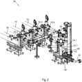
- reference numeral 10 refers generally to part of a pressure exchange chamber (PEC) pumping system in accordance with the prior art.
- the PEC pumping system 10 includes three PEGs 11.1, 11.2, and 11.3 defined by lengths of pipe 12, 14, 16 (which act as pump chambers) and associated valves.
- the associated valves include three medium or pumped fluid valve arrangements 18, 20, 22, which are connected respectively to the pipes 12, 14, 16 at a medium entry ends thereof.
- the associated valves also include three driving fluid valve arrangements 19, 21, 23, which are connected, respectively, to the lengths of pipe 12, 14, 16 at the driving fluid entry ends thereof, i.e., longitudinally spaced from the medium valve arrangements 18, 20, 22.
- Each medium valve arrangement 18, 20, 22 includes a medium inlet valve 18.1, 20.1, 22.1 whereby medium to be pumped can be admitted into the associated PEC 11.1, 11.2, 11.3 and a medium outlet valve 18.2, 20.2, 22.2 whereby pumped medium can be discharged from the PEC 11.1, 11.2, 11.3 along a discharge pipe 24 (which may be a riser).
- each driving fluid valve arrangement 19, 21, 23 includes an inlet valve 19.1, 21.1, 23.1 through which a high-pressure driving fluid can be admitted into the associated PEC 11.1, 11.2, 11.3 and an outlet valve 19.2, 21.2, 23.2 whereby driving fluid can be discharged from the associated PEC 11.1, 11.2, 11.3.
- the PEC pumping system 10 further includes a feed arrangement, part of which is generally indicated by reference numeral 26, configured to feed medium to be pumped to the medium inlet valves 18.1, 20.1, 22.1 as described in more detail herebelow.
- the feed arrangement 26 includes a feeder or delivery pump (not shown) having a suction side and a discharge side, although other pump arrangements are possible.
- the feeder pump is typically a centrifugal pump which can pump a medium which includes fairly large solid particles, e.g., particle sizes between 2mm and 60mm. with some particles up to approximately 100mm.
- the feed arrangement 26 further includes a common feed pipe 32 which is connected to a discharge side of the feeder pump and three feed lines 35, 36, 37 each of which has an upstream end connected to the common feed pipe 32 and a downstream end.
- the downstream ends of the feed lines 35, 36, 37 are connected , respectively, to the medium inlet valves 18.1, 20.1, 22.1.
- medium to be pumped is pumped from the centrifugal pump through the pipe 32 and the feed lines 35, 36, 37 to the medium inlet valves 18.1, 20.1, 22.1.
- the medium inlet valve 18.1, 20.1, 22,1 is opened and the corresponding driving fluid outlet valve 19.2, 21.2, 23.2 is opened, so that medium enters the associated pipe 12, 14, 16 and displaces the driving fluid out of that pipe 12, 14, 16 through the associated driving fluid outlet valve 19.2, 21.2, 23.2.
- the associated medium inlet valve 18.1, 20.1, or 22,1 and the associated driving fluid outlet valve 19.2, 21.2, or 23.2 are closed.
- the volume in the relevant pipe 12, 14, 16 is pressurised (by a compression step) and then the medium outlet valve 18.2, 20.2, or 22.2 and the associated driving fluid inlet valve 19.1, 21.1, or 23.1 are opened such that high-pressure driving fluid enters that PEC pipe 12, 14, or 16 and displaces the medium out of the pipe 12, 14, or 16 through the medium outlet valve 18.2, 20.2, or 22.2 and into the discharge pipe 24.
- the associated medium outlet valve and driving fluid inlet valve close, the pipe 12, 14, or 16 is decompressed, and the medium inlet valve and driving fluid outlet valve open, once again, to charge the pipe 12, 14, or 16 with medium in the manner described above.
- valves of the different PEGs 11.1, 11.2, 11.3 is staggered such that the filling of the PECs 11.1, 11.2, 11.3 with medium and the discharge of medium occurs in a more or less continuous basis.
- reference numeral 50 refers generally to an embodiment of a PEC pumping system in accordance with the invention. Unless otherwise indicated, like reference numerals used above are used to designate similar parts.
- the PEC pumping system 50 of the present invention makes use of a distribution manifold generally indicated by reference numeral 52.
- the distribution manifold 52 replaces the feed lines 35, 36, 37 in the prior art PEC system 10 and provides an interface between the common feed pipe 32 and the medium inlet valves 18.1, 20.1, 22.1.
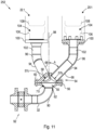
- the distribution manifold 52 includes a hollow body 54 defining a distribution chamber 55.
- the body 54 includes a domed or frusto-conical base 56 and a domed or frusto-conical top 58 which is secured to the base by circumferentially spaced bolts 60 extending through complementary annular flanges.
- the distribution manifold 52 includes an inlet 62 which extends through the base 56 and an inlet pipe 90 having a downstream end which is connected, e.g., by welding, to the base 56 and an upstream end which is connected to the pipe 32 by means of a coupling 92 thereby connecting the inlet 62 in flow communication with the discharge side of the feeder pump.
- the medium inlet valves 18.1, 20.1, 22.1 are in the form of cone valves which have a downwardly facing inlet and are positioned in a spaced apart configuration above the distribution manifold 52.
- Three equiangularly spaced apart upwardly open outlets 57a, 57b, 57c extend through the top 58 and are connected to the inlets of the medium inlet valves 18.1, 20.1, 22.1 by feed lines 64, 66, 68, respectively.
- Each feed line 64, 66, 68 comprises a length of pipe having a straight lower section 94 and a curved upper section 96.
- the lower ends of the lower sections 94 are secured to the top 58, e.g., by welding, such that they extend upwardly outwardly away from the top 58 at an angle of inclination A relative to a vertical center line 98 through a centre of the distribution manifold 52.
- the upper sections 96 curve upwardly and a flange 100 is connected to the upper end of the upper section whereby the feed line 64, 66, 68 is connected to the associated medium inlet valve 18.1, 20.1, 22.1.
- each of the feed lines 64, 66, 68 is inclined downwardly for its entire length from its downstream end which is in flow communication with the inlet of the associated medium inlet valve 18.1, 20.1, 22.1 to its upstream end connected in flow communication with the distribution chamber 55 defined in the body 54 of the distribution manifold 52.
- the PEC pumping system 50 functions in substantially the identical manner to the PEC pumping system 10 described above.
- solids contained in the feed line will settle and flow downwardly, under the influence of gravity, along the feed line towards the distribution chamber 55 of the distribution manifold 52.
- the lower part of the distribution chamber 55 defines a sump 70 (best seen in Figure 7 ) having sloping sides and into which the solids settle from each of the feed lines 64, 66, 68 when their respective medium inlet valves are closed. Solids which flow back into the distribution chamber 55, and which collect in the sump 70, will be entrained in the medium passing through the distribution chamber 55 and be fed along the feed line connected to whichever medium inlet valve which is open.
- the flow of medium through the distribution manifold 52 is illustrated in a first operative condition of the PEC pumping system 50 in which the medium inlet valve 22.1 is open and the medium inlet valve 20.1 is closed.
- medium is fed along the pipe 32 in the direction of arrow 80.
- the medium passes through the inlet pipe 90 and enters the distribution chamber 55 through the inlet 62.
- the medium exits the chamber 55 through the outlet 57c and flows along the feed line 68 connected to the medium inlet valve 22.1 as indicated by arrow 82 (which indicates the slurry feed flow direction in both Figures 8 and 9 ). Since the medium inlet valve 20.1 is closed the medium in the feed line 66 is stationary.
- the flow of medium through the distribution manifold 52 is illustrated in a second operative condition in which the medium inlet valve 22.1 is closed and the medium inlet valve 20.1 is open.
- medium is fed along the pipe 32 in the direction of arrow 80.
- the medium passes through the inlet pipe 90 and enters the distribution chamber 55 through the inlet 62.
- the medium exits the chamber 55 through the outlet 57b and flows along the feed line 66 connected to the medium inlet valve 20.1 as indicated by arrow 82. Since the medium inlet valve 22.1 is closed the medium in the feed line 68 is stationary.
- Solid particles which settle in the feed line 68 flow downwardly under the influence of gravity, as illustrated by arrow 84, back through the outlet 57c into the distribution chamber 55 where they are entrained in the medium flowing through the chamber and fed to the open medium inlet valve 20.1.
- the angle of inclination A of the feed lines 64, 66, 68 is selected to ensure that solids settling in the feed line do in fact flow back towards the distribution chamber 55.
- the angle of inclination A is between 0°, i.e., vertical, and approximately 75° for some types of slurry (e.g., where the particles are spherical and roll), although for many embodiments the angle will be between approximately 25° and 60°, such as approximately 40° to 50°.
- An additional advantage of the invention is that the concentration of solids in the medium can be increased substantially from the current level, for example, up to approximately 25%. This in turn allows more solids to be pumped for a given power input or alternatively for a smaller system to be used to pump the same volume of solids as may be pumped with the prior art.
- the outlets 57a,b,c may not be equally (or equiangularly) spaced around a central axis 98 of the manifold 52.
- an alternative distribution manifold 152 is shown in Figure 10 .
- This distribution manifold 152 may be used in embodiments where the PECs 11.1, 11.2, 11.3 are located at different heights or altitudes).
- the distribution manifold 152 comprises four outlet 157a,b,c,d each being coupled to a respective feed line 164, 166, 168 and 169; and each of the outlets 157a,b,c,d being vertically spaced (or offset) from its adjacent outlet.
- the distribution manifold 152 comprises an elongate body 154 extending generally vertically and defining a circular or cylindrical distribution chamber 155 therein.
- a distribution manifold 252 may include a vertical spacing pipe 102 between the upper section 96 and the flange 100 associated with each outlet 57a,b,c.
- the medium inlet valves 18.1, 20.1, 22.1 each define a chamber 104 in which a valve seat 106 is mounted.
- a valve body 108 moves within the chamber 104 towards and away from the valve seat 106 to close and open the valve, respectively.
- the vertical spacing pipe 102 is provided to assist with flow of solid particles downwardly under the influence of gravity, away from that part of the chamber 104 beneath the valve body 108 and down the vertical spacing pipe 102.
- the volume of the upper section 96 and the vertical spacing pipe 102 combined equals or is greater than the volume of the chamber 104 of the medium input valve 18.1.
- vertical spacing pipe 102 may be incorporated into the upper section 96 to provided an upper section having an extended vertical portion immediately below the flange 100.
- an input vertical spacing pipe may be provided between the inlet pipe 90 and the base 56.
- a PEC pumping system could be constructed in the first instance accordance with the invention.
- the components of the PEC pumping system could be transported in knocked-down or kit form for assembly on site.
- a PEC pumping system in accordance with the prior art (such as shown in Fig. 1 ) could be modified by installing a distribution manifold and inclined feed lines as described above.
Landscapes
- Engineering & Computer Science (AREA)
- Mechanical Engineering (AREA)
- General Engineering & Computer Science (AREA)
- Jet Pumps And Other Pumps (AREA)
- Structures Of Non-Positive Displacement Pumps (AREA)
- Details Of Reciprocating Pumps (AREA)
- Feeding, Discharge, Calcimining, Fusing, And Gas-Generation Devices (AREA)
Claims (13)
- Verteiler (52, 152, 252) für ein Druckaustauschkammer-Pumpsystem (10, 50) mit einer Vielzahl von parallel angeordneten Druckaustauschkammern (11.1, 11.2, 11.3), umfassend:einen hohlen Verteilerkörper (54, 154), der eine Verteilerkammer (55, 155) definiert und in einer aufrechten Ausrichtung positioniert ist und eine zentrale, aufrechte Achse (98) definiert;einen in den Körper (54, 154) führenden Einlass (62) zur Aufnahme des zu pumpenden Mediums, das in einer Flüssigkeit transportierte Feststoffteilchen umfasst;eine Vielzahl von beabstandeten Auslässen (57, 157), die sich betriebsmäßig nach oben aus dem Verteilerkörper (54, 154) heraus öffnen; undeine Vielzahl von Rohren (64, 66, 68, 164, 166, 168, 169), wobei sich jedes Rohr von einem jeweiligen Auslass (57, 157) nach oben zu einem zugehörigen Mediumeinlassventil (18.1, 20.1, 22.1) einer der Druckaustauschkammern erstreckt und die Rohre (64, 66, 68, 164, 166, 168, 169) um die Mittelachse (98) des Verteilers (52, 152, 252) herum beabstandet sind und jedes Rohr (64, 66, 68, 164, 166, 168, 169) in einem Winkel im Bereich von etwa 20 Grad bis 80 Grad relativ dazu geneigt ist, wobei die Mediumeinlassventile (18.1, 20.1, 22.1) aufrecht ausgerichtet sind, sodass sich beim Schließen eines Mediumeinlassventils (18.1, 20.1, 22.1) Feststoffteilchen aufgrund der Schwerkraft in der zugehörigen Leitung (64, 66, 68, 164, 166, 168, 169) absetzen und von dem Mediumeinlassventil (18.1, 20.1, 22.1) wegbewegen, um dessen Verstopfung zu verhindern.
- Verteiler nach Anspruch 1, wobei der Körper (54, 154) eine Basis (56) und eine Oberseite (58) beinhaltet, die an der Basis (56) befestigt ist, um die Verteilerkammer (55, 155) zu definieren, wobei sich der Einlass (62) durch die Basis (56) und die Auslässe (57, 157) durch die Oberseite (58) erstreckt.
- Verteiler nach Anspruch 1 oder 2, wobei jedes Rohr (64, 66, 68, 164, 166, 168, 169) an seinem stromaufwärts gelegenen Ende eine Kopplungsausbildung (92) aufweist, über die es mit einem zugehörigen Mediumeinlassventil (18.1, 20.1, 22.1) verbunden werden kann.
- Verteiler nach Anspruch 1 oder 2, wobei die Rohre (64, 66, 68, 164, 166, 168, 169) in gleichem Winkelabstand um die Mittelachse (98) des Verteilers (52, 152, 252) beabstandet sind.
- Verteiler nach Anspruch 4, wobei der Neigungswinkel im Bereich von etwa 40 Grad bis 50 Grad liegt.
- Verteiler nach einem der Ansprüche 2 bis 5, der ein Einlassrohr (90) beinhaltet, dessen stromabwärts gelegenes Ende mit der Basis (56) verbunden ist und dessen stromaufwärts gelegenes Ende an die Medienversorgung angeschlossen werden kann, um den Einlass (62) des Verteilers (52, 152, 252) mit der Medienversorgung in Strömungsverbindung zu bringen.
- Verteiler nach Anspruch 6, wobei am stromaufwärts gelegenen Ende des Einlassrohrs (90) eine Verbindungsausbildung vorgesehen ist, um mit einer Zuleitung (35, 36, 37) verbunden zu werden, die in Strömungsverbindung mit einer Auslassseite einer Zufuhrpumpe steht.
- Gemeinsame Medieneingabevorrichtung, umfassend einen Verteiler (52, 152, 252) nach einem der vorhergehenden Ansprüche und eine Vielzahl von Mediumeingabeventilen (18.1, 20.1, 22.1); wobei jedes der Rohre (64, 66, 68, 164, 166, 168, 169) ein stromaufwärts gelegenes Ende aufweist, das mit einem der Auslässe (57, 157) verbunden ist, und ein stromabwärts gelegenes Ende, das mit einem zugehörigen Mediumeinlassventil (18.1, 20.1, 22.1) verbunden werden kann, wobei jedes Rohr (64, 66, 68, 164, 166, 168, 169) betriebsmäßig von dem Körper (54, 154) weg nach oben geneigt ist, sodass das stromaufwärts gelegene Ende im Gebrauch auf einem niedrigeren Niveau positioniert ist als das stromabwärts gelegene Ende.
- Verfahren zum Betreiben eines Druckaustauschkammer-Pumpsystems (10, 50) mit zumindest einer Druckaustauschkammer (11.1, 11.2, 11.3), das die Zufuhr eines Mediums beinhaltet, das Feststoffteilchen umfasst, die in einer Flüssigkeit zu einem aufrechten Mediumeinlassventil (18.1, 20.1, 22.1) der Druckaustauschkammer (11.1, 11.2, 11.3) entlang eines Strömungswegs durch einen Verteilerkörper (54, 154) transportiert werden und einem Rohr (64, 66, 68, 164, 166, 168, 169), dessen stromaufwärts gelegenes Ende mit dem Verteilerkörper (54, 154) verbunden ist und dessen stromabwärts gelegenes Ende mit dem Mediumeinlassventil (18.1, 20.1, 22.1) verbunden und höher als das stromaufwärts gelegene Ende positioniert ist, sodass sich beim Schließen eines Mediumeinlassventils (18.1, 20.1, 22.1) Feststoffteilchen durch die Schwerkraft in dem zugehörigen Rohr (64, 66, 68, 164, 166, 168, 169) absetzen, und zwar weg von dem Mediumeinlassventil (18.1, 20.1, 22.1), um dessen Verstopfung zu verhindern.
- Verfahren nach Anspruch 9, das, wenn das Druckaustauschkammer-Pumpsystem (10, 50) eine Vielzahl von Druckaustauschkammern (11.1, 11.2, 11.3) umfasst, das Zuführen von Medium von einer Verteilerkammer (55, 155) zu einem Mediumeinlassventil (18.1, 20.1, 22.1) der oder jeder Druckaustauschkammer (11.1, 11.2, 11.3) entlang eines geneigten Strömungswegs beinhaltet, sodass sich in einem Strömungsweg absetzende Feststoffe unter Schwerkraft zur Verteilerkammer (55, 155) zugeführt werden.
- Verfahren nach Anspruch 10, das das Zuführen von zu pumpendem Medium von einer Förderpumpe in die Verteilerkammer (55, 155) und von der Verteilerkammer (55, 155) entlang des zugehörigen Strömungswegs zu dem oder jedem Mediumeinlassventil (18.1, 20.1, 22.1) beinhaltet, das offen ist und zumindest einen Teil der Feststoffe, die sich in einem mit einem geschlossenen Mediumeinlassventil (18.1, 20.1, 22.1) verbundenen Strömungsweg absetzen, zurück in die Verteilerkammer (55, 155) zuführt, um in dem durch die Verteilerkammer (55, 155) und entlang eines Strömungswegs zu einem offenen Mediumeinlassventil (18.1, 20.1, 22.1) strömenden Medium mitgerissen zu werden.
- Druckaustauschkammer-Pumpsystem (10, 50), umfassend:(i) zumindest eine Druckaustauschkammer (11.1, 11.2, 11.3);(ii) eine Zuführanordnung (26) zum Zuführen eines Mediums, das in einer Flüssigkeit transportierte Feststoffteilchen umfasst, in die Druckaustauschkammer (11.1, 11.2, 11.3); und(iii)eine gemeinsame Medieneingabevorrichtung nach Anspruch 8, die sowohl mit der zumindest einen Druckaustauschkammer (11.1, 11.2, 11.3) als auch mit der Zufuhranordnung (26) gekoppelt ist.
- Druckaustauschkammer-Pumpsystem nach Anspruch 12, das eine Vielzahl von parallel angeordneten Druckaustauschkammern (11.1, 11.2, 11.3) beinhaltet.
Applications Claiming Priority (2)
| Application Number | Priority Date | Filing Date | Title |
|---|---|---|---|
| GB2202050.7A GB2615761B (en) | 2022-02-16 | 2022-02-16 | Distribution manifold |
| PCT/IB2023/050989 WO2023156873A1 (en) | 2022-02-16 | 2023-02-03 | Distribution manifold |
Publications (3)
| Publication Number | Publication Date |
|---|---|
| EP4419799A1 EP4419799A1 (de) | 2024-08-28 |
| EP4419799C0 EP4419799C0 (de) | 2024-12-11 |
| EP4419799B1 true EP4419799B1 (de) | 2024-12-11 |
Family
ID=80820829
Family Applications (1)
| Application Number | Title | Priority Date | Filing Date |
|---|---|---|---|
| EP23705072.9A Active EP4419799B1 (de) | 2022-02-16 | 2023-02-03 | Verteilerverteiler |
Country Status (8)
| Country | Link |
|---|---|
| US (1) | US20250066143A1 (de) |
| EP (1) | EP4419799B1 (de) |
| JP (1) | JP7769796B2 (de) |
| CN (1) | CN118434976A (de) |
| AU (1) | AU2023222266B2 (de) |
| GB (1) | GB2615761B (de) |
| WO (1) | WO2023156873A1 (de) |
| ZA (1) | ZA202405701B (de) |
Families Citing this family (1)
| Publication number | Priority date | Publication date | Assignee | Title |
|---|---|---|---|---|
| GB2630140A (en) * | 2023-05-19 | 2024-11-20 | Weir Minerals Netherlands Bv | Dump valve arrangement |
Family Cites Families (10)
| Publication number | Priority date | Publication date | Assignee | Title |
|---|---|---|---|---|
| JPH0673144U (ja) * | 1993-03-26 | 1994-10-11 | 石川島播磨重工業株式会社 | スラリ供給装置 |
| US7063276B2 (en) * | 2004-03-23 | 2006-06-20 | Agri-Inject, Inc. | System for uniform dispersal of agricultural chemicals |
| US7621728B2 (en) * | 2004-06-10 | 2009-11-24 | Miller J Davis | Pump inlet manifold |
| US7264423B2 (en) * | 2005-02-02 | 2007-09-04 | Cnh Canada, Ltd. | Hose restraint apparatus |
| PL216367B1 (pl) * | 2009-05-14 | 2014-03-31 | Int Tobacco Machinery Poland | Sposób i urządzenie do dystrybucji krajanki tytoniowej do zasilania maszyn produkujących papierosy |
| US9441776B2 (en) * | 2012-01-25 | 2016-09-13 | S.P.M. Flow Control, Inc. | Manifold and methods of manufacturing same |
| US9585304B2 (en) * | 2014-10-17 | 2017-03-07 | Cnh Industrial America Llc | 3-way seed flow splitter for planters |
| WO2016178956A1 (en) * | 2015-05-01 | 2016-11-10 | Schlumberger Technology Corporation | Dynamic solids concentration variation via pressure exchange device |
| US20170227002A1 (en) * | 2016-02-08 | 2017-08-10 | Trican Well Service Ltd. | Cryogenic pump and inlet header |
| GB2575638A (en) * | 2018-07-16 | 2020-01-22 | Weir Minerals Netherlands Bv | Pumping system |
-
2022
- 2022-02-16 GB GB2202050.7A patent/GB2615761B/en active Active
-
2023
- 2023-02-03 AU AU2023222266A patent/AU2023222266B2/en active Active
- 2023-02-03 EP EP23705072.9A patent/EP4419799B1/de active Active
- 2023-02-03 US US18/724,161 patent/US20250066143A1/en active Pending
- 2023-02-03 WO PCT/IB2023/050989 patent/WO2023156873A1/en not_active Ceased
- 2023-02-03 JP JP2024529211A patent/JP7769796B2/ja active Active
- 2023-02-03 CN CN202380014842.XA patent/CN118434976A/zh active Pending
-
2024
- 2024-07-23 ZA ZA2024/05701A patent/ZA202405701B/en unknown
Also Published As
| Publication number | Publication date |
|---|---|
| AU2023222266B2 (en) | 2025-04-10 |
| EP4419799C0 (de) | 2024-12-11 |
| JP2024544575A (ja) | 2024-12-03 |
| ZA202405701B (en) | 2025-11-26 |
| GB2615761B (en) | 2024-06-19 |
| CN118434976A (zh) | 2024-08-02 |
| AU2023222266A1 (en) | 2024-05-16 |
| EP4419799A1 (de) | 2024-08-28 |
| US20250066143A1 (en) | 2025-02-27 |
| WO2023156873A1 (en) | 2023-08-24 |
| GB2615761A (en) | 2023-08-23 |
| GB202202050D0 (en) | 2022-03-30 |
| JP7769796B2 (ja) | 2025-11-13 |
Similar Documents
| Publication | Publication Date | Title |
|---|---|---|
| US8110024B2 (en) | Separator tank for separation of fluid comprising water, oil and gas,use of such a tank, and method for separating a fluid including water, oil, and gas | |
| US10717026B1 (en) | Well production separation systems and methods | |
| EP4419799B1 (de) | Verteilerverteiler | |
| CN111852552A (zh) | 充填料浆制备系统及其制备方法 | |
| AU2012247204B2 (en) | Method and apparatus for particle separation | |
| US11845085B2 (en) | Feed system for grinding bodies in vertical mills | |
| NL2030358B1 (en) | Intelligent modular pneumatic conveying device | |
| US11913320B1 (en) | Mobile fracturing sand plant and systems and methods of operating same | |
| CN110360165A (zh) | 一种双级射流泵设计方法及装置 | |
| EP1532064B1 (de) | Fluidisiervorrichtung | |
| CN204549457U (zh) | 流态化并联仓泵输送系统 | |
| CN110642016B (zh) | 一种粗颗粒煤浆管道喂料系统及其喂料方法 | |
| CN210097935U (zh) | 一种低能耗高效分矿器 | |
| CN202325664U (zh) | 地上组装式矿井充填装置 | |
| CN109158221A (zh) | 一种改进泡沫泵安装方式的铜硫矿选矿系统 | |
| CN214637389U (zh) | 一种旋流器和深锥浓缩仓联合浓缩造浆一体机 | |
| CN209034565U (zh) | 一种改进泡沫泵安装方式的铜硫矿选矿系统 | |
| WO2007017737A1 (en) | Transportation of particulate material | |
| CN222196021U (zh) | 可拆卸式仓储浓密机 | |
| CN120736266A (zh) | 一种流态仓放浆装置及其操作方法 | |
| CN214811545U (zh) | 一种基于石灰石浆液品质监控的湿式球磨机制浆系统 | |
| US8062519B2 (en) | Gasket distributor | |
| CN210068027U (zh) | 一种油田智能化钻井一级固控环保系统 | |
| CN102099446A (zh) | 连续排出固体材料的气化装置 | |
| RU2632081C1 (ru) | Узел подготовки пульпы из золошлаковых отходов |
Legal Events
| Date | Code | Title | Description |
|---|---|---|---|
| STAA | Information on the status of an ep patent application or granted ep patent |
Free format text: STATUS: UNKNOWN |
|
| STAA | Information on the status of an ep patent application or granted ep patent |
Free format text: STATUS: THE INTERNATIONAL PUBLICATION HAS BEEN MADE |
|
| PUAI | Public reference made under article 153(3) epc to a published international application that has entered the european phase |
Free format text: ORIGINAL CODE: 0009012 |
|
| STAA | Information on the status of an ep patent application or granted ep patent |
Free format text: STATUS: REQUEST FOR EXAMINATION WAS MADE |
|
| 17P | Request for examination filed |
Effective date: 20240522 |
|
| AK | Designated contracting states |
Kind code of ref document: A1 Designated state(s): AL AT BE BG CH CY CZ DE DK EE ES FI FR GB GR HR HU IE IS IT LI LT LU LV MC ME MK MT NL NO PL PT RO RS SE SI SK SM TR |
|
| GRAP | Despatch of communication of intention to grant a patent |
Free format text: ORIGINAL CODE: EPIDOSNIGR1 |
|
| STAA | Information on the status of an ep patent application or granted ep patent |
Free format text: STATUS: GRANT OF PATENT IS INTENDED |
|
| GRAS | Grant fee paid |
Free format text: ORIGINAL CODE: EPIDOSNIGR3 |
|
| GRAA | (expected) grant |
Free format text: ORIGINAL CODE: 0009210 |
|
| STAA | Information on the status of an ep patent application or granted ep patent |
Free format text: STATUS: THE PATENT HAS BEEN GRANTED |
|
| INTG | Intention to grant announced |
Effective date: 20241014 |
|
| AK | Designated contracting states |
Kind code of ref document: B1 Designated state(s): AL AT BE BG CH CY CZ DE DK EE ES FI FR GB GR HR HU IE IS IT LI LT LU LV MC ME MK MT NL NO PL PT RO RS SE SI SK SM TR |
|
| DAV | Request for validation of the european patent (deleted) | ||
| DAX | Request for extension of the european patent (deleted) | ||
| REG | Reference to a national code |
Ref country code: GB Ref legal event code: FG4D |
|
| REG | Reference to a national code |
Ref country code: CH Ref legal event code: EP |
|
| REG | Reference to a national code |
Ref country code: IE Ref legal event code: FG4D |
|
| REG | Reference to a national code |
Ref country code: DE Ref legal event code: R096 Ref document number: 602023001337 Country of ref document: DE |
|
| U01 | Request for unitary effect filed |
Effective date: 20241211 |
|
| U07 | Unitary effect registered |
Designated state(s): AT BE BG DE DK EE FI FR IT LT LU LV MT NL PT RO SE SI Effective date: 20241223 |
|
| U20 | Renewal fee for the european patent with unitary effect paid |
Year of fee payment: 3 Effective date: 20250227 |
|
| PG25 | Lapsed in a contracting state [announced via postgrant information from national office to epo] |
Ref country code: HR Free format text: LAPSE BECAUSE OF FAILURE TO SUBMIT A TRANSLATION OF THE DESCRIPTION OR TO PAY THE FEE WITHIN THE PRESCRIBED TIME-LIMIT Effective date: 20241211 |
|
| PG25 | Lapsed in a contracting state [announced via postgrant information from national office to epo] |
Ref country code: ES Free format text: LAPSE BECAUSE OF FAILURE TO SUBMIT A TRANSLATION OF THE DESCRIPTION OR TO PAY THE FEE WITHIN THE PRESCRIBED TIME-LIMIT Effective date: 20241211 |
|
| PG25 | Lapsed in a contracting state [announced via postgrant information from national office to epo] |
Ref country code: NO Free format text: LAPSE BECAUSE OF FAILURE TO SUBMIT A TRANSLATION OF THE DESCRIPTION OR TO PAY THE FEE WITHIN THE PRESCRIBED TIME-LIMIT Effective date: 20250311 |
|
| PG25 | Lapsed in a contracting state [announced via postgrant information from national office to epo] |
Ref country code: GR Free format text: LAPSE BECAUSE OF FAILURE TO SUBMIT A TRANSLATION OF THE DESCRIPTION OR TO PAY THE FEE WITHIN THE PRESCRIBED TIME-LIMIT Effective date: 20250312 |
|
| PG25 | Lapsed in a contracting state [announced via postgrant information from national office to epo] |
Ref country code: RS Free format text: LAPSE BECAUSE OF FAILURE TO SUBMIT A TRANSLATION OF THE DESCRIPTION OR TO PAY THE FEE WITHIN THE PRESCRIBED TIME-LIMIT Effective date: 20250311 |
|
| PG25 | Lapsed in a contracting state [announced via postgrant information from national office to epo] |
Ref country code: SM Free format text: LAPSE BECAUSE OF FAILURE TO SUBMIT A TRANSLATION OF THE DESCRIPTION OR TO PAY THE FEE WITHIN THE PRESCRIBED TIME-LIMIT Effective date: 20241211 |
|
| PG25 | Lapsed in a contracting state [announced via postgrant information from national office to epo] |
Ref country code: PL Free format text: LAPSE BECAUSE OF FAILURE TO SUBMIT A TRANSLATION OF THE DESCRIPTION OR TO PAY THE FEE WITHIN THE PRESCRIBED TIME-LIMIT Effective date: 20241211 |
|
| PG25 | Lapsed in a contracting state [announced via postgrant information from national office to epo] |
Ref country code: IS Free format text: LAPSE BECAUSE OF FAILURE TO SUBMIT A TRANSLATION OF THE DESCRIPTION OR TO PAY THE FEE WITHIN THE PRESCRIBED TIME-LIMIT Effective date: 20250411 |
|
| PG25 | Lapsed in a contracting state [announced via postgrant information from national office to epo] |
Ref country code: SK Free format text: LAPSE BECAUSE OF FAILURE TO SUBMIT A TRANSLATION OF THE DESCRIPTION OR TO PAY THE FEE WITHIN THE PRESCRIBED TIME-LIMIT Effective date: 20241211 |
|
| PG25 | Lapsed in a contracting state [announced via postgrant information from national office to epo] |
Ref country code: CZ Free format text: LAPSE BECAUSE OF FAILURE TO SUBMIT A TRANSLATION OF THE DESCRIPTION OR TO PAY THE FEE WITHIN THE PRESCRIBED TIME-LIMIT Effective date: 20241211 |
|
| PG25 | Lapsed in a contracting state [announced via postgrant information from national office to epo] |
Ref country code: MC Free format text: LAPSE BECAUSE OF FAILURE TO SUBMIT A TRANSLATION OF THE DESCRIPTION OR TO PAY THE FEE WITHIN THE PRESCRIBED TIME-LIMIT Effective date: 20241211 |
|
| PLBE | No opposition filed within time limit |
Free format text: ORIGINAL CODE: 0009261 |
|
| STAA | Information on the status of an ep patent application or granted ep patent |
Free format text: STATUS: NO OPPOSITION FILED WITHIN TIME LIMIT |
|
| 26N | No opposition filed |
Effective date: 20250912 |
|
| PG25 | Lapsed in a contracting state [announced via postgrant information from national office to epo] |
Ref country code: IE Free format text: LAPSE BECAUSE OF NON-PAYMENT OF DUE FEES Effective date: 20250203 |