EP4418758A2 - Verfahren zur leistungsregelung für drahtlose kommunikation und kommunikationsvorrichtung und netzwerkelement damit - Google Patents
Verfahren zur leistungsregelung für drahtlose kommunikation und kommunikationsvorrichtung und netzwerkelement damit Download PDFInfo
- Publication number
- EP4418758A2 EP4418758A2 EP24154076.4A EP24154076A EP4418758A2 EP 4418758 A2 EP4418758 A2 EP 4418758A2 EP 24154076 A EP24154076 A EP 24154076A EP 4418758 A2 EP4418758 A2 EP 4418758A2
- Authority
- EP
- European Patent Office
- Prior art keywords
- power
- mode
- reference signal
- transmission
- rsrp
- Prior art date
- Legal status (The legal status is an assumption and is not a legal conclusion. Google has not performed a legal analysis and makes no representation as to the accuracy of the status listed.)
- Pending
Links
- 238000000034 method Methods 0.000 title claims abstract description 46
- 238000004891 communication Methods 0.000 title claims abstract description 37
- 230000005540 biological transmission Effects 0.000 claims abstract description 146
- 238000005259 measurement Methods 0.000 claims description 44
- 230000011664 signaling Effects 0.000 claims description 44
- 238000004364 calculation method Methods 0.000 claims description 28
- 230000004044 response Effects 0.000 claims description 12
- 238000010586 diagram Methods 0.000 description 68
- 238000009825 accumulation Methods 0.000 description 17
- 230000008859 change Effects 0.000 description 14
- 238000006243 chemical reaction Methods 0.000 description 6
- 230000006978 adaptation Effects 0.000 description 5
- 238000009795 derivation Methods 0.000 description 5
- 230000006870 function Effects 0.000 description 5
- 238000001228 spectrum Methods 0.000 description 4
- 238000012545 processing Methods 0.000 description 3
- 230000000694 effects Effects 0.000 description 2
- 238000001914 filtration Methods 0.000 description 2
- 101710192523 30S ribosomal protein S9 Proteins 0.000 description 1
- CIWBSHSKHKDKBQ-JLAZNSOCSA-N Ascorbic acid Chemical compound OC[C@H](O)[C@H]1OC(=O)C(O)=C1O CIWBSHSKHKDKBQ-JLAZNSOCSA-N 0.000 description 1
- 230000004913 activation Effects 0.000 description 1
- 230000003139 buffering effect Effects 0.000 description 1
- 238000012790 confirmation Methods 0.000 description 1
- 230000007246 mechanism Effects 0.000 description 1
- 230000009467 reduction Effects 0.000 description 1
- 239000007787 solid Substances 0.000 description 1
Images


















Classifications
-
- H—ELECTRICITY
- H04—ELECTRIC COMMUNICATION TECHNIQUE
- H04W—WIRELESS COMMUNICATION NETWORKS
- H04W72/00—Local resource management
- H04W72/04—Wireless resource allocation
- H04W72/044—Wireless resource allocation based on the type of the allocated resource
- H04W72/0473—Wireless resource allocation based on the type of the allocated resource the resource being transmission power
-
- H—ELECTRICITY
- H04—ELECTRIC COMMUNICATION TECHNIQUE
- H04W—WIRELESS COMMUNICATION NETWORKS
- H04W52/00—Power management, e.g. Transmission Power Control [TPC] or power classes
- H04W52/04—Transmission power control [TPC]
- H04W52/18—TPC being performed according to specific parameters
- H04W52/24—TPC being performed according to specific parameters using SIR [Signal to Interference Ratio] or other wireless path parameters
- H04W52/242—TPC being performed according to specific parameters using SIR [Signal to Interference Ratio] or other wireless path parameters taking into account path loss
-
- H—ELECTRICITY
- H04—ELECTRIC COMMUNICATION TECHNIQUE
- H04W—WIRELESS COMMUNICATION NETWORKS
- H04W52/00—Power management, e.g. Transmission Power Control [TPC] or power classes
- H04W52/04—Transmission power control [TPC]
- H04W52/06—TPC algorithms
- H04W52/14—Separate analysis of uplink or downlink
- H04W52/143—Downlink power control
-
- H—ELECTRICITY
- H04—ELECTRIC COMMUNICATION TECHNIQUE
- H04W—WIRELESS COMMUNICATION NETWORKS
- H04W52/00—Power management, e.g. Transmission Power Control [TPC] or power classes
- H04W52/04—Transmission power control [TPC]
- H04W52/30—Transmission power control [TPC] using constraints in the total amount of available transmission power
- H04W52/32—TPC of broadcast or control channels
-
- H—ELECTRICITY
- H04—ELECTRIC COMMUNICATION TECHNIQUE
- H04W—WIRELESS COMMUNICATION NETWORKS
- H04W52/00—Power management, e.g. Transmission Power Control [TPC] or power classes
- H04W52/04—Transmission power control [TPC]
- H04W52/30—Transmission power control [TPC] using constraints in the total amount of available transmission power
- H04W52/36—Transmission power control [TPC] using constraints in the total amount of available transmission power with a discrete range or set of values, e.g. step size, ramping or offsets
-
- H—ELECTRICITY
- H04—ELECTRIC COMMUNICATION TECHNIQUE
- H04W—WIRELESS COMMUNICATION NETWORKS
- H04W72/00—Local resource management
- H04W72/12—Wireless traffic scheduling
- H04W72/1263—Mapping of traffic onto schedule, e.g. scheduled allocation or multiplexing of flows
- H04W72/1268—Mapping of traffic onto schedule, e.g. scheduled allocation or multiplexing of flows of uplink data flows
-
- H—ELECTRICITY
- H04—ELECTRIC COMMUNICATION TECHNIQUE
- H04W—WIRELESS COMMUNICATION NETWORKS
- H04W72/00—Local resource management
- H04W72/12—Wireless traffic scheduling
- H04W72/1263—Mapping of traffic onto schedule, e.g. scheduled allocation or multiplexing of flows
- H04W72/1273—Mapping of traffic onto schedule, e.g. scheduled allocation or multiplexing of flows of downlink data flows
-
- H—ELECTRICITY
- H04—ELECTRIC COMMUNICATION TECHNIQUE
- H04W—WIRELESS COMMUNICATION NETWORKS
- H04W72/00—Local resource management
- H04W72/20—Control channels or signalling for resource management
- H04W72/21—Control channels or signalling for resource management in the uplink direction of a wireless link, i.e. towards the network
-
- H—ELECTRICITY
- H04—ELECTRIC COMMUNICATION TECHNIQUE
- H04W—WIRELESS COMMUNICATION NETWORKS
- H04W72/00—Local resource management
- H04W72/20—Control channels or signalling for resource management
- H04W72/23—Control channels or signalling for resource management in the downlink direction of a wireless link, i.e. towards a terminal
-
- H—ELECTRICITY
- H04—ELECTRIC COMMUNICATION TECHNIQUE
- H04W—WIRELESS COMMUNICATION NETWORKS
- H04W52/00—Power management, e.g. Transmission Power Control [TPC] or power classes
- H04W52/02—Power saving arrangements
- H04W52/0203—Power saving arrangements in the radio access network or backbone network of wireless communication networks
- H04W52/0206—Power saving arrangements in the radio access network or backbone network of wireless communication networks in access points, e.g. base stations
-
- H—ELECTRICITY
- H04—ELECTRIC COMMUNICATION TECHNIQUE
- H04W—WIRELESS COMMUNICATION NETWORKS
- H04W52/00—Power management, e.g. Transmission Power Control [TPC] or power classes
- H04W52/04—Transmission power control [TPC]
- H04W52/06—TPC algorithms
- H04W52/08—Closed loop power control
-
- H—ELECTRICITY
- H04—ELECTRIC COMMUNICATION TECHNIQUE
- H04W—WIRELESS COMMUNICATION NETWORKS
- H04W52/00—Power management, e.g. Transmission Power Control [TPC] or power classes
- H04W52/04—Transmission power control [TPC]
- H04W52/06—TPC algorithms
- H04W52/10—Open loop power control
-
- H—ELECTRICITY
- H04—ELECTRIC COMMUNICATION TECHNIQUE
- H04W—WIRELESS COMMUNICATION NETWORKS
- H04W52/00—Power management, e.g. Transmission Power Control [TPC] or power classes
- H04W52/04—Transmission power control [TPC]
- H04W52/06—TPC algorithms
- H04W52/14—Separate analysis of uplink or downlink
- H04W52/146—Uplink power control
Definitions
- the disclosure is related to a method of power control for wireless communication, and a communication device and a network element using the same.
- a network element may switch between an energy saving mode and a normal power mode based on, for example, the traffic load of the network.
- FIG. 1 illustrates a schematic diagram of incorrect transmission power derivation. If a base station (BS) 10 switches from the normal power mode to the energy saving (ES) mode, the adaptation of antenna number and/or transmission power of the BS 10 may be changed, and the beam coverage and/or transmission (Tx)/receiving (Rx) beam pattern of the BS 10 may be changed (e.g., beam coverage may be reduced) accordingly. Since power control (PC) parameters related to the uplink (UL) transmission may not be adapted correspondingly, it may lead to issues such as poor communication quality or wastage of power in user equipment (UE) 20. Therefore, mechanisms to handle incorrect transmission power derivation issues for various ES schemes are required.
- PC power control
- the disclosure is directed to a method of power control for wireless communication, and a communication device and a network element using the same.
- a method of power control for wireless communication adapted to a communication device, comprising: determining an uplink transmission power for a cell in a first transmission occasion according to a parameter set, wherein the parameter set comprises a first nominal power, a downlink pathloss estimate, and a first power control adjustment.
- a method of power control for wireless communication adapted to a network element, comprising: transmitting a first configuration of a parameter set for a cell, wherein the parameter set comprises a first nominal power and a downlink pathloss estimate.
- a communication device comprising a processor and a transceiver.
- the processor is coupled to the transceiver, wherein the processor is configured to: determine an uplink transmission for a cell in a first transmission occasion according to a parameter set, wherein the parameter set comprises a first nominal power, a downlink pathloss estimate, and a first power control adjustment.
- a network element comprising a processor and a transceiver.
- the processor is coupled to the transceiver, wherein the processor is configured to: transmit a first configuration of a parameter set for a cell, wherein the parameter set comprises a first nominal power.
- the following embodiments provide a power control method for UL transmission between a network element and a communication device.
- the method of the present disclosure may also be applied in a downlink (DL) transmission.
- DL transmission the functions or steps executed by the network element in the following embodiments may be executed by the communication device, and vice versa - the functions or steps executed by the communication device in the following embodiments may be executed by the network element.
- the PDCCH/PDSCH transmission for UL transmission in the following embodiments may be replaced by the PUCCH/PUSCH transmission for DL transmission.
- the communication device may be represented by UE and the network element may be represented by BS, but not limited herein.
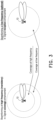
- FIG. 2 illustrates a schematic diagram of coverages of BS 10.
- the 5G new radio may extend operation frequency to above 6GHz for better transmission efficiency.
- path loss may be believed to be much more severe in propagation at mmWave frequencies due to insufficient coverage.
- the coverage of BS 10 in the above-6GHz spectrum may be smaller than the coverage of BS 10 in the sub-6GHz spectrum.
- the number of deployed BS 10 needs to be increased, and the cost for base station deployment will also increase.
- FIG. 3 illustrates a schematic diagram of beamforming in 3GPP 5G NR.
- the BS 10 may generate beamformed signal by multiple antennas.
- the BS 10 may perform beamforming at high operation frequency for signal coverage enhancement, and the BS may perform beamforming at low operation frequency for signal reception enhancement.
- FIG. 4 illustrates a schematic diagram of the power consumption of a transceiver unit (TXRU) of a BS.
- a BS may activate one or more TXRU 40 (i.e., active antenna unit (AAU)) for operations such as analog-to-digital conversion (ADC), digital-to-analog conversion (DAC), up frequency conversion, or down frequency conversion, but the present disclosure is not limited herein.
- AAU active antenna unit
- FIG. 5 illustrates a schematic diagram of a network element for energy saving according to an embodiment of the present disclosure.
- the network element in the present disclosure may refer to the BS 10, a network (NW), a transmission reception point (TRP), a smart repeater, a remote radio head (RRH), a reconfigurable intelligent surface (RIS), wherein RRH/RIS/Repeater may assist BS/TRP for robust coverage.
- the network element may perform energy saving based on, for example, low traffic load.
- a UL transmission power P(q PL , i,j) with index j (e.g., index of transmission occasion) and i (index of cell) may be derived by equation (1), wherein P CMAX,C is a configured maximum allowed transmission power for cell C, P 0 ( j ) is a target received power at BS (e.g., gNB) side, ⁇ is a fractional power control factor, PL ( q PL ) is a DL pathloss estimate calculated by the UE using PL-RS resource index (e.g., q PL ) , f(i) is a transmission power control (TPC) command, M RB ( i ) is the number of allocated resource blocks, and ⁇ TF ( i ) is a MCS related power adjustment (the more bits per resource element, the higher value of ⁇ TF ( i )) .
- P CMAX,C is a configured maximum allowed transmission power for cell C
- P 0 ( j ) + ⁇ ⁇ PL ( q PL )) may be regarded as parameter for open-loop power control, and (10 log 10 ⁇ 2 ⁇ M RB ( i ) ⁇ + ⁇ TF ( i ) + f ( i )) may be regarded as parameter for closed-loop power control.
- P q PL i j min ⁇ P CMAX , C P 0 j + ⁇ ⁇ PL q PL + 10 log 10 2 ⁇ M RB i + ⁇ TF i + f i dBm
- FIG. 7 illustrates a schematic diagram 70 of DL path loss estimation according to an embodiment of the present disclosure.
- DL pathloss estimate PL ( q PL ) calculated by the UE using PL-RS resource index (e.g., q PL ) may be derived by equation (3), wherein P Tx ( q PL ) is an average EPRE of the resource elements that the network used for PL-RS transmission (i.e., P Tx ( q PL ) is the transmission power of the PL-RS q PL ) and RSRP L3 ( q PL ) is a L3-RSRP for PL-RS at UE side.
- PL q PL P Tx q PL ⁇ RSRP L 3 q PL
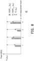
- the first measurement result of L3-RSRP may be represented as equation (4-1), wherein RSRP L3 , 1 ( q PL ) is the first measurement result of L3-RSRP of PL-RS q PL and RSRP L 1,1 ( q PL ) is the first measurement result of L1-RSRP of PL-RS q PL .
- the nth (n> 1) measurement result of L3-RSRP may be represented as equation (4-2), wherein "a” is a filter coefficient (0 ⁇ a ⁇ 1), RSRP L 3 ,n -1 ( q PL ) is the (n-1)th measurement result of L3-RSRP of PL-RS q PL , and RSRP L 1 ,n ( q PL ) is the nth measurement result of L1-RSRP of PL-RS q PL .
- FIG. 8 shows a schematic diagram 80 of calculation of L3-RSRP (and L1-RSRP) for the first four measurement result.
- An accumulated TPC f(i) (i.e., power control adjustment) at transmission occasion i may be represented as equation (5), wherein f(i-1) is the accumulated TPC at transmission occasion (i-1), M is the number of received TPC command value during a time period between the UL transmission occasion (i-1) and UL transmission occasion i, and ⁇ ( m ) is the mth TPC command value.
- FIG. 9 illustrates a schematic diagram 90 of accumulated TPC f(i) according to an embodiment of the present disclosure, wherein M is assumed to be 3.
- FIG. 10 illustrates a schematic diagram 100 of accumulated TPC f(i) and time windows according to an embodiment of the present disclosure.
- M in the equation (5) may be defined as the number of received TPC command value during a window, wherein the window for calculating f(i) may be K(i-1) symbols of occasion (i-1) (i.e., time period between DCI#1 and PUSCH#1 of occasion (i-1)), and the window for calculating f(i+1) may be K(i) symbols of occasion i (i.e., time period between DCI#2 and PUSCH#2 of occasion i).
- Each of TPC command value may be indicated by a DCI (e.g., DCI for UL transmission).
- ⁇ (0), ⁇ (1), or ⁇ (2) may be indicated by the DCI#1.
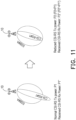
- FIG. 11 illustrates a schematic diagram of power domain energy saving (e.g., adaptation of transmission power) according an embodiment of the present disclosure.
- the BS 10 may reduce power for transmission of, for example, CSI-RS or PDSCH for energy saving purposes.
- the pattern of CSI-RS#1 for DL transmission may change after the BS 10 reduces the normal CSI-RS Tx power from P1 to P2.
- the pattern of CSI-RS#1 for LTL transmission may change after the BS reduces the received CSI-RS Rx power from P1" to P2".
- the UE may receive a configuration of a list of sub configurations (also referred to as second configuration), wherein each of sub configuration of the list of sub configurations may be associated with a power offset for receiving a reference signal (e.g., SSB#A or CSI-RS#1 in the NP mode, or SSB#A' or CSI-RS#1' in the ES mode).
- a reference signal e.g., SSB#A or CSI-RS#1 in the NP mode, or SSB#A' or CSI-RS#1' in the ES mode.
- FIG. 12 illustrates a schematic diagram of spatial domain energy saving (e.g., adaptation of TXRU number) according to an embodiment of the present disclosure.
- the BS 10 may have a plurality of TXRUs such as TXRU1 ⁇ TXRU4 and TXRU1 ⁇ TXRU4 are turned on for transmission of SSB#A (or CSI-RS#1) if the BS 10 is in the normal power mode (also referred to as second mode). If the BS 10 switch from the normal power mode to the spatial domain ES mode, the BS 10 may turn off some of the TXRUs such as TXRU2 and TXRU3.
- the beam pattern of SSB#A' (or CSI-RS#1') of BS 10 in the ES mode may be different from the beam pattern of SSB#A (or CSI-RS#1) of BS 10 in the normal power mode, even if the configuration of SSB#A' (or CSI-RS#1') may be the same as the configuration of SSB#A (or CSI-RS#1).
- the UE may receive a configuration of a list of sub configurations, wherein each of sub configuration of the list of sub configurations may be associated with an antenna port subset for receiving a reference signal (e.g., SSB#A or CSI-RS#1 in the NP mode, or SSB#A' or CSI-RS#1' in the ES mode).
- a reference signal e.g., SSB#A or CSI-RS#1 in the NP mode, or SSB#A' or CSI-RS#1' in the ES mode.
- FIG. 13 illustrates a schematic diagram of combination of power domain energy saving and spatial domain energy saving according to an embodiment of the present disclosure.
- the BS 10 may turn off one or more TXRUs, antenna elements, and/or CSI-RS resources for energy saving purposes.
- the BS 10 may turn off CSI-RS#A1, CSI-RS#A2, CSI-RS#A3, CSI-RS#A4, and CSI-RS#A5 after the BS 10 switching from the normal power mode to the ES mode.
- FIG. 14-15 illustrate schematic diagrams of issues of DL pathloss estimation according to an embodiment of the present disclosure.
- the UE may derive an incorrect pathloss power estimation based on the PL-RS measurement results before and after the mode changing.
- PL-RS measurement results may be impacted by, for example, the effect of path loss or low mobility. For example, assume the UE measures a L3-RSRP RSRP L 3, n 0 in occasion n 0 when the BS 10 is in NP mode.
- the UE may measure a L1-RSRP in occasion n 1 RSRP L 1, n 1 when the BS 10 is in ES mode.
- PL-RS measurement results may be impacted by, for example, the effect of path loss or low mobility.
- the UE measures a L3-RSRP RSRP L 3, n 0 in occasion n 0 when the BS 10 is in NP mode. If the BS 10 switches from the NP mode to the ES mode by performing power reduction, the UE may measure a L1-RSRP in occasion n 1 RSRP L 1, n 1 when the BS 10 is in ES mode.
- the UE should derive the DL path loss estimate PL ( q PL ) based on average EPRE P Tx,ES ( q PL ) of the REs that the BS10 used for PL-RS transmission in ES mode.
- FIG. 16 illustrates a schematic diagram of issue of insufficient target received power P 0 at BS 10 side according to an embodiment of the present disclosure.
- the measurement object of the UE may be changed from a reference signal (e.g., PL-RS) to another reference signal (e.g., reference signal with different transmission power or different ID), and the result of UL transmission power derivation may be incorrect.
- a reference signal e.g., PL-RS
- another reference signal e.g., reference signal with different transmission power or different ID
- the target received power P 0 at BS 10 side may be insufficient due to insufficient UL transmission power P 0 _UE (i.e., offset adjustment according to CSI-RS QCLed with the SSB) of LTE 20.
- FIG. 17 illustrates a schematic diagram of issue of TPC command accumulation according to an embodiment of the present disclosure.
- Different modes may introduce different channel properties.
- the UE may derivate an incorrect UL transmission power.
- the BS switches from the normal power mode to the energy saving mode (also referred to as first mode) at time point T 1 , wherein the LTE receive a TPC command value ⁇ (0) in occasion (i-1) before T 1 and receive another TPC command value ⁇ (1) in occasion i after T 1 .
- the UE accumulate the TPC command f(i) based on the equation 17, the UE may derivate an incorrect UL transmission power since f(i - 1) + ⁇ (0) and ⁇ (1) belong to different power modes respectively.
- FIG. 18 illustrates a schematic diagram of beam patterns of BS 10 in different power modes according to an embodiment of the present disclosure.
- the UL transmission related PC parameters under different power modes are shown in Table 1.
- UL PC parameters may need to be adjusted if
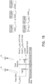
- the UL power control may not be associated with network energy saving methods. If a BS 10 switches to the ES mode (e.g., adaptation of TXRU number and/or transmission power), the UL transmission related PC parameters may not be adapted correspondingly. Thus, the UE may derivate an incorrect UL Tx power. For example, when the BS 100 switches from the normal power mode to an energy saving mode, the beam coverage of the BS 10 may be reduced and/or the Tx/Rx beam pattern of the BS 10 may be changed. Since L3-RSRP filter and UL Tx power transmission derivation of the UE 20 may not be adapted correspondingly, improper UL power which may reduce the communication quality or increase the power consumption may be applied by the UE 20, as shown in FIG. 19 .
- a UE may determine an UL transmission power for a cell in a transmission occasion according to a parameter set, wherein the parameter set may include a nominal power P 0 ( j ), a DL pathloss estimate PL ( q PL ) , and a power control adjustment f(i).
- the UE may receive a configuration of a parameter set for a cell and may obtain the nominal power P 0 ( j ) and confirmation of RS for calculating the DL pathloss estimate PL ( q PL ) from the BS.
- the UE may calculate the DL pathloss estimate PL ( q PL ) according to an explicit ES-mode specific Tx power of a PL-RS.
- FIG. 20 illustrates a schematic diagram of transmission power of power mode according to an embodiment of the present disclosure.
- the UE may be configured with a RS power for the normal power mode and one or more RS powers for the energy saving mode.
- the UE may be configured with RS power #0 for the NP mode and may be configured with RS power #1 (or RS power_ES) for the ES mode, wherein RS power #1 (or RS power_ES) may be less than RS power #0.
- the UE may reset L3-RSRP filter if the UE receives an indicator for power mode changing.
- a UE may be configured with a PL-RS (e.g., with a first PL-RS ID) included in a configuration of pathloss estimate by receiving the configuration of pathloss estimate, wherein the PL-RS may be configured with one or more transmission powers such as a first transmission power corresponding to the PL-RS of the NP mode and/or a second transmission power corresponding to the PL-RS of the ES mode.
- the UE may apply the corresponding transmission power (e.g., first transmission power or second transmission power) for the PL-RS.
- the UE may calculate the DL pathloss estimate PL ( q PL ) according to the transmission power of the PL-RS according to the configuration of pathloss estimate. For example, if the UE receives a signaling for changing to NP mode, the UE may calculate the DL pathloss estimate PL ( q PL ) according to the first transmission power. If the UE receives signaling for changing to ES mode, the LTE may calculate the DL pathloss estimate PL ( q PL ) according to the second transmission power.
- the UE may derive PL ( q PL ) according to the measurement object such as q PL corresponding to the new power mode.
- the UE may derive the DL pathloss estimate PL ( q PL ) by resetting a calculation of the RSRP.
- FIG. 21 and FIG. 22 illustrate schematic diagrams of calculation of DL pathloss estimate according to an embodiment of the present disclosure.
- the UE may reset L3-RSRP filter.
- the UE may reset L3-RSRP filter.
- the UE may calculate the DL pathloss estimate PL ( q PL ) according to a power offset.
- FIG. 23 illustrates a schematic diagram of transmission power of power mode according to an embodiment of the present disclosure.
- the UE may be configured with a RS power for the NP mode and one or more power offsets (e.g., P offset ) for the ES mode.
- the UE may configured with RS power #0 for the NP mode and may be configured with (RS power #0- P offset ) for the ES mode.
- the UE in response to a measurement object (e.g., PL-RS) for DL pathloss estimate changing from a reference signal to another reference signal (e.g., reference signal with different transmission power), i.e., the LTE changes from a power mode (e.g., NP mode) to a different power mode (e.g., ES mode), the UE may update a calculation of the RSRP by the power offset.
- FIG. 24 illustrates a schematic diagram of compensate power offset in L1-RSRP in ES mode according to an embodiment of the present disclosure.
- the UE in response to a measurement object (e.g., PL-RS) for DL path estimate changing from a reference signal to another reference signal (e.g., reference signal with different PL-RS ID), the UE may reset a calculation of the RSRP by, for example, resetting the L3-RSRP filter.
- the UE may apply the corresponding PL-RS (e.g., PL-RS corresponding to the NP mode or PL-RS corresponding to the ES mode) for the channel or the RS to estimate the DL pathloss.
- FIG. 25 illustrates a schematic diagram of beam pattern of power mode according to an embodiment of the present disclosure.
- the UE may be configured with a PL-RS ID for the normal power mode and one or more PL-RS IDs for the energy saving mode.
- the measurement object e.g., PL-RS
- the transmission powers of PL-RS ID#0 and PL-RS ID_ES may be the same.
- the UE may calculate the DL pathloss estimate PL ( q PL ) according to an implicit ES-mode specific PL-RS.
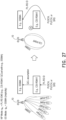
- FIG. 26 and FIG. 27 illustrate schematic diagrams of transmission power for ES mode according to an embodiment of the present disclosure.
- a CSI-RS transmitted by the BS 10 may be quasi co-located with a reference signal such as SSB#A.
- the BS 100 may reduce CSI-RS transmission power for energy saving mode.
- the UE may be configured with a PL-RS ID for NP mode but may not be configured with a PL-RS ID for ES mode.
- a PL-RS (e.g., CSI-RS) is quasi co-located with a RS (e.g., SSB)
- the UE may apply the PL-RS (e.g., CSI-RS) corresponding to the PL-RS ID for calculating the DL pathloss estimate if the signaling indicates the LTE to change to the NP mode
- the LTE may apply the RS (e.g., SSB) for calculating the DL pathloss estimate if the signaling indicates the UE to change to the ES mode.
- the UE may reset L3-RSRP filter.
- CSI-RS#A1 transmitted by the BS 10 is quasi co-located with SSB#A.
- FIG. 28 illustrates a flowchart of determining a measurement object for the LTE according to an embodiment of the present disclosure, wherein the measurement object may be used for calculating the DL pathloss estimate.
- the UE may determine the power mode currently being applied. If the BS or the UE is in the NP mode, the UE may execute step S282. If the BS or the US is in the ES mode, the UE may execute step S283.
- the LTE may determine a first PL-RS as the measurement object according to a first configuration (e.g., configuration of PL - RS NP , wherein PL - RS NP represents PL-RS for NP mode).
- a first configuration e.g., configuration of PL - RS NP , wherein PL - RS NP represents PL-RS for NP mode.
- step S283 the UE may determine whether a PL - RS ES (i.e., PL-RS for ES mode) corresponding to the ES mode is configured. If the UE is configured with PL - RS ES , the UE may execute step S285. If the UE is not configured with PL - RS ES , the UE may execute step S284.
- a PL - RS ES i.e., PL-RS for ES mode
- the UE may determine a second PL-RS as the measurement object according to a spatial relation of the first PL-RS. For example, the UE may determine an SSB quasi co-located with the first PL-RS as the measurement object.
- the UE may determine a second PL-RS as the measurement object, wherein the second PL-RS may be the configured PL - RS ES .
- the UE may determine whether the reset the calculation of the RSRP according to a time period between two power mode changings.
- FIG. 29 illustrates a schematic diagram of power mode changing according to an embodiment of the present disclosure. Assume the UE 20 change from the normal power mode to the energy saving mode at time point T 0 , and the UE 20 change from the energy saving mode back to the normal power mode at tie point T 1 . The UE 20 may determine whether to reset L3-RSRP filter (i.e., reset a calculation of RSRP) based on the time period T 1 - T 0 .
- L3-RSRP filter i.e., reset a calculation of RSRP
- L3-RSRP before mode changing e.g., L3-RSRP of transmission occasion n 0
- L3-RSRP of transmission occasion n 0 may still valid even after the mode changing back. That is, L3-RSRP of transmission occasion n 0 may be used for calculation of L3-RSRP of transmission occasion n 1 .
- the LTE may start a timer. If the LTE receives another signaling for changing from the second power mode back to the first power mode at time point T 1 before the timer expires (or if time period T 1 - T 0 is less than or equal to a threshold), the UE may not reset the L3-RSRP filter.
- the first power mode e.g., normal power mode
- the second power mode e.g., energy saving mode
- the triggering condition for resetting L3-RSRP filter may be met and the LTE may reset the L3-RSRP filter when the UE is back to the first power mode.
- the timer of the first power mode may be stopped by the UE after the UE changes back to the first power mode.
- the UE may be configured with one or more L3-RSRP filter, wherein each L3-RSRP filter may be associated with a power mode (e.g., normal power mode or energy saving mode).
- a L3-RSRP filter may be associated with mode 0 (i.e., normal power mode) and another L3-RSRP filter may be associated with mode 1 (i.e., energy saving mode).
- FIG. 30 illustrates a schematic diagram of resetting of L3-RSRP filter according to an embodiment of the present disclosure.
- the LTE 20 may be configured with one or more timer of mode (e.g., T max,Mode ) for resetting the L3-RSRP filter of the power mode.
- T max,Mode timer of mode
- the UE 20 in the normal power mode receives a signaling for changing from the normal power mode to the energy saving mode at time point T 0
- the UE 20 receives a signaling for changing from the energy saving mode back to the normal power mode at time point T 2 .
- FIG. 31 illustrates a schematic diagram of resetting of L3-RSRP filter according to an embodiment of the present disclosure.
- the LTE 20 may be configured with one or more timer of mode (e.g., T max,Mode ) for resetting the L3-RSRP filter of the power mode.
- T max,Mode timer of mode
- the UE 20 in the normal power mode receives a signaling for changing from the normal power mode to the energy saving mode at time point T 0
- the UE 20 receives a signaling for changing from the energy saving mode back to the normal power mode at time point T 2 .
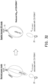
- FIG. 32 illustrates a schematic diagram of explicit ES-mode specific offset power according to an embodiment of the present disclosure.
- the UE 20 may be configured with one or more offset powers, wherein each offset power P 0_ UE,Mode may be associated with a power mode.
- the UE 20 may determine the P 0_ UE,mode according to a signaling for power mode changing.
- the UE 20 may calculate the nominal power P 0 ( j ) according to the target received power P 0_ Nominal , j (or a second nominal power) at BS 10 and the offset power P 0_ UE,mode based on equation (2).
- FIG. 33 illustrates a schematic diagram of explicit ES-mode specific parameter ⁇ according to an embodiment of the present disclosure, wherein ⁇ may be a fractional power control factor.
- the UE may be configured with one or more parameters ⁇ , wherein each parameter ⁇ may be associated with a power mode.
- FIG. 34 illustrates a schematic diagram of implicit ES-mode specific offset power according to an embodiment of the present disclosure.
- a CSI-RS transmitted by the BS 10 may be quasi co-located with a reference signal such as SSB#A.
- the BS 10 may reduce CSI-RS transmission power for energy saving mode.
- the UE may be configured with a one or more parameters ⁇ for various transmission occasions, wherein ⁇ may be a fractional power control factor.
- the window may be between a first symbol (or a first set of symbols or a first symbol set) before an UL transmission at a first transmission occasion (e.g., transmission occasion i) and a second symbol (or a second set of symbols or a second symbol set) before an UL transmission at a second transmission occasion (e.g., transmission occasion (i-1)).
- f i mode f i ⁇ 1
- mode + ⁇ m 0 M ⁇ 1 ⁇ m mode
- FIG. 35 illustrates a schematic diagram 350 of ES-mode specific TPC command accumulation according to an embodiment of the present disclosure.
- the UE receives a signaling for changing from a first power mode (e.g., the normal power mode) to second power mode (e.g., the energy saving mode) at time point T 1 .
- the UE may reset a calculation of power control adjustment at time point T 1 (i.e., reset TPC command accumulation at time point T 1 ).
- the UE may be configured with one or more timers of mode (e.g., T max,mode ) for resetting TPC command accumulation (i.e., calculation of power control adjustment), wherein the timer may be timeAlimentTimer.
- T max,mode timers of mode
- the LTE may start or restart the timer T max,mode .
- the UE may not reset TPC command accumulation.
- the UE may not reset TPC command accumulation if the UE receives another signaling for changing from the second power mode back to the first power mode at a second time point after the timer T max,mode expires (or if time period between the second time point and the first time point is greater than the threshold).
- the triggering condition for resetting the TPC command accumulation may be met and the UE may reset the TPC command accumulation when the UE is back to the first power mode. That is, the UE may reset the calculation of the power control adjustment for first power mode.
- the timer T max,mode of the first power mode may be stopped by the UE after the UE changes back to the first power mode.
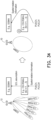
- FIG. 36 illustrates a schematic diagram of resetting of TPC command accumulation based on a timer according to an embodiment of the present disclosure.
- the UE 20 in the normal power mode receives a signaling for changing from the normal power mode to the energy saving mode at time point T 0 and the UE 20 receives a signaling for changing from the energy saving mode back to the normal power mode at time point T 2 .
- FIG. 37 illustrates a schematic diagram of resetting of TPC command accumulation based on a timer according to an embodiment of the present disclosure.
- the UE 20 in the normal power mode receives a signaling for changing from the normal power mode to the energy saving mode at time point T 0 and the UE 20 receives a signaling for changing from the energy saving mode back to the normal power mode at time point T 1 .
- LTE not supporting the ES mode may receive a reconfiguration for updating DL power control related parameters (e.g., PL-RS ID, transmission power of PL-RS ID, P 0 , or TPC command value).
- DL power control related parameters e.g., PL-RS ID, transmission power of PL-RS ID, P 0 , or TPC command value.
- the UE not supporting the ES mode may receive an indication for Scell (e.g., Cell#a) de-activation, and the LTE may receive another indication for Scell (e.g., Cell#b) activation.
- an indication for Scell e.g., Cell#a
- the LTE may receive another indication for Scell (e.g., Cell#b) activation.
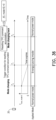
- FIG. 38 illustrates a schematic diagram of communication device 380 according to an embodiment of the present disclosure, wherein the communication device 380 may execute the functions or steps implemented by the LTE (e.g., LTE 20) in the embodiments corresponding to FIG. 1 to FIG. 37 .
- the communication device 380 may include a processor 381, a storage medium 382, and a transceiver 383.
- the processor 381 is, for example, a graphics processing unit (GPU), an image signal processor (ISP), an image processing unit (IPU), a central processing unit (CPU), another programmable general purpose or special purpose micro control unit (MCU), a microprocessor, a digital signal processor (DSP), a programmable controller, a special application specific integrated circuit (ASIC), an arithmetic logic unit (ALU), a complex programmable logic device (CPLD), a field programmable gate array (FPGA) or other similar components or a combination of the foregoing components.
- the processor 381 may be coupled to the storage medium 382 and the transceiver 383, and may access and excrete a plurality of modules and various application programs stored in the storage medium 382.
- the storage medium 382 is, for example, any type of fixed or removable random access memory (RAM), a read-only memory (ROM), a flash memory, a hard disk drive (HDD), a solid state drive (SSD), or similar components or a combination of the foregoing components, and is configured to store the plurality of modules or various application programs that can be executed by the processor 381.
- RAM random access memory
- ROM read-only memory
- HDD hard disk drive
- SSD solid state drive
- the transceiver 383 may be configured to transmit or receive wireless signals.
- the transceiver 383 may also perform operations such as low noise amplifying, impedance matching, frequency mixing, up or down frequency conversion, filtering, amplifying, and so forth.
- the transceiver 383 may include one or more digital-to-analog (D/A) converters or analog-to-digital (A/D) converters.
- D/A digital-to-analog
- A/D analog-to-digital
- FIG. 39 illustrates a schematic diagram of network element 390 according to an embodiment of the present disclosure, wherein the network element 390 may execute the functions or steps implemented by the BS (e.g., BS 10) in the embodiments corresponding to FIG. 1 to FIG. 37 .
- the network element 390 may include a processor 391, a storage medium 392, and a transceiver 393.
- the processor 391 is, for example, a GPU, an ISP, an IPU, a CPU, another programmable general purpose or special purpose MCU, a microprocessor, a DSP, a programmable controller, a special ASIC, an ALU, a CPLD, a FPGA or other similar components or a combination of the foregoing components.
- the processor 391 may be coupled to the storage medium 392 and the transceiver 393, and may access and excrete a plurality of modules and various application programs stored in the storage medium 392.
- the storage medium 392 is, for example, any type of fixed or removable RAM, a ROM, a flash memory, a HDD, a SSD, or similar components or a combination of the foregoing components, and is configured to store the plurality of modules or various application programs that can be executed by the processor 391.
- the transceiver 393 may be configured to transmit or receive wireless signals.
- the transceiver 393 may also perform operations such as low noise amplifying, impedance matching, frequency mixing, up or down frequency conversion, filtering, amplifying, and so forth.
- the transceiver 393 may include one or more D/A converters or A/D converters.
- FIG. 40 illustrates a flowchart of a method of power control for wireless communication according to an embodiment of the present disclosure, wherein the method may be implemented by the communication device 380 as shown in FIG. 38 .
- step S401 determining an uplink transmission power for a cell in a first transmission occasion according to a parameter set, wherein the parameter set comprises a first nominal power, a downlink pathloss estimate, and a first power control adjustment.
- FIG. 41 illustrates a flowchart of a method of power control for wireless communication according to an embodiment of the present disclosure, wherein the method may be implemented by the network element 390 as shown in FIG. 39 .
- step S411 transmitting a first configuration of a parameter set for a cell, wherein the parameter set comprises a first nominal power.
- the present disclosure provides a method of transmission power control for the communication device and/or the network element.
- the communication device may automatically adjust UL transmission power to adapt the beam coverage or the beam pattern of the network element after the network element turning into energy saving mode or back to normal power mode. Accordingly, the robustness of wireless communication may be improved and the power consumption of the communication device (or network element) may be reduced.
- a cell in the present disclosure may include a serving cell, a carrier or a CC (component carrier), a serving cell, MCG (master cell group), or SCG (second cell group), but not limited herein.
- RRC in the present disclosure may be replaced by MAC CE or DCI, but not limited herein.
- Power in the present disclosure may be maximum output power, EIRP (effective isotropic radiated power), total radiated power, radiated power, minimum peak EIRP, maximum EIRP, max total radiated power, spherical coverage, configured transmitted power, P-max, maximum total transmit power, or power class, but not limited herein.
- EIRP effective isotropic radiated power
- total radiated power radiated power
- radiated power minimum peak EIRP
- maximum EIRP maximum total radiated power
- spherical coverage configured transmitted power, P-max, maximum total transmit power, or power class, but not limited herein.
- LTL transmission in the present disclosure may be PUSCH, PUCCH, PRACH, SRS, or RS, but not limited herein.
- a RS in the present disclosure may include a DL RS and/or a LTL RS.
- a DL RS configuration in the present disclosure may be associated with a DM-RS group, a DM-RS group index, a DM-RS resource, a DM-RS resource index, a DM-RS port index, a DM-RS port, a CSI-RS resource set index, a CSI-RS resource set, a CSI-RS resource index, a CSI-RS resource, a CSI-RS port index, a CSI-RS port, a SSB resource set index, a SSB resource set, a SSB resource index, a SSB resource, a SSB resource, a SSB port index, or a SSB port, but not limited herein.
- a LTL RS configuration in the present disclosure may be associated with a DM-RS group, a DM-RS group index, a DM-RS resource, a DM-RS resource index, a DM-RS port index, a DM-RS port, a RACH group, a RACH group index, A RACH resource, a RACH resource index, a SRS resource set index, a SRS resource set, a SRS resource index, a SRS resource, a SRS port index, or a SRS port, but not limited herein.
- a beam in the present disclosure may be represented by an antenna, an antenna port, an antenna element, a group of antenna, a group of antenna port, a group of antenna element, a spatial domain filter, a reference signal resource, or a QCL assumption, but not limited herein.
- a first beam may be represented as a first antenna port, a first group of antenna port or a first spatial domain filter.
- a first beam direction may be represented as a QCL assumption or a spatial domain filter.
- a Rx beam configuration in the present disclosure may include a spatial Rx parameter, a spatial domain receive filter, or a panel, but not limited herein.
- a Tx beam configuration in the present disclosure may include a spatial Tx parameter, a spatial domain transmission filter, or a panel, but not limited herein.
- An index or an identity of the present disclosure may include CORESETPoolIndex, TRP ID, or Panel ID, but not limited here.
- a cell TRP in the present disclosure may be a TRP, a serving cell, a gNodeB (gNB), a panel, an unlicensed cell, an unlicensed serving cell, an unlicensed TRP, an eNodeB (evolved NodeB), or an eNB, but not limited herein.
- gNB gNodeB
- eNodeB evolved NodeB
- a configured grant in the present disclosure may be a configured grant configuration or configuredGrantConfigIndex, but not limited herein.
- a communication device in the present disclosure may be represented by UE, or gNodeB, but not limited herein.
- Embodiments disclosed in the present disclosure may apply for unlicensed band, licensed band, non-DRX mode, DRX mode, energy saving, or power saving, but not limited herein.
Landscapes
- Engineering & Computer Science (AREA)
- Computer Networks & Wireless Communication (AREA)
- Signal Processing (AREA)
- Mobile Radio Communication Systems (AREA)
Priority Applications (2)
| Application Number | Priority Date | Filing Date | Title |
|---|---|---|---|
| US18/424,844 US20240284344A1 (en) | 2023-02-17 | 2024-01-28 | Method of power control for wireless communication, and communication device and network element using the same |
| TW113104384A TWI921732B (zh) | 2023-02-17 | 2024-02-05 | 無線通訊的功率控制方法及使用其的通訊裝置和網路元件 |
Applications Claiming Priority (1)
| Application Number | Priority Date | Filing Date | Title |
|---|---|---|---|
| US202363446358P | 2023-02-17 | 2023-02-17 |
Publications (2)
| Publication Number | Publication Date |
|---|---|
| EP4418758A2 true EP4418758A2 (de) | 2024-08-21 |
| EP4418758A3 EP4418758A3 (de) | 2024-10-16 |
Family
ID=89767439
Family Applications (1)
| Application Number | Title | Priority Date | Filing Date |
|---|---|---|---|
| EP24154076.4A Pending EP4418758A3 (de) | 2023-02-17 | 2024-01-26 | Verfahren zur leistungsregelung für drahtlose kommunikation und kommunikationsvorrichtung und netzwerkelement damit |
Country Status (3)
| Country | Link |
|---|---|
| US (1) | US20240284344A1 (de) |
| EP (1) | EP4418758A3 (de) |
| CN (1) | CN118524526A (de) |
Families Citing this family (1)
| Publication number | Priority date | Publication date | Assignee | Title |
|---|---|---|---|---|
| US12507179B2 (en) * | 2022-12-29 | 2025-12-23 | Dish Wireless L.L.C. | Wireless communication systems for dynamically scaling power of synchronization signal block and channel state information reference signal |
Family Cites Families (13)
| Publication number | Priority date | Publication date | Assignee | Title |
|---|---|---|---|---|
| KR101677787B1 (ko) * | 2009-10-02 | 2016-11-18 | 인터디지탈 패튼 홀딩스, 인크 | 다수의 안테나들을 갖는 디바이스들에 대한 전력 제어 |
| WO2018204887A1 (en) * | 2017-05-04 | 2018-11-08 | Ofinno Technologies, Llc | Rach power offset |
| EP4075884A1 (de) * | 2017-06-16 | 2022-10-19 | Huawei Technologies Co., Ltd. | Verfahren und systeme zur leistungsregelung für uplink-übertragung |
| US10945172B2 (en) * | 2017-11-16 | 2021-03-09 | Comcast Cable Communications, Llc | Power control for bandwidth part switching |
| US10887843B2 (en) * | 2018-05-11 | 2021-01-05 | Lenovo (Singapore) Pte. Ltd. | Method and apparatus for transmitting an uplink transmission based on a pathloss estimate |
| WO2020144540A1 (en) * | 2019-01-10 | 2020-07-16 | Lenovo (Singapore) Pte. Ltd. | Uplink power control |
| EP4005297A1 (de) * | 2019-08-14 | 2022-06-01 | Ofinno, LLC | Leistungsregelung in der trägeraggregation mit mehreren sendeempfangspunkten |
| US11191031B2 (en) * | 2019-09-15 | 2021-11-30 | Qualcomm Incorporated | Path-loss estimation using path-loss reference signal activation and deactivation |
| US11729723B2 (en) * | 2019-11-21 | 2023-08-15 | Qualcomm Incorporated | Power control indication for multiple services |
| WO2022208490A1 (en) * | 2021-04-03 | 2022-10-06 | Telefonaktiebolaget Lm Ericsson (Publ) | Ul power control for transport block transmission over multiple slots |
| CA3191602A1 (en) * | 2022-03-01 | 2023-09-01 | Comcast Cable Communications, Llc | Measurement reporting for energy saving state |
| CN119213826A (zh) * | 2022-05-17 | 2024-12-27 | 高通股份有限公司 | 发送配置指示特定的虚拟功率净空报告 |
| US20240107461A1 (en) * | 2022-09-22 | 2024-03-28 | Qualcomm Incorporated | Csi enhancement for sbfd configuration |
-
2024
- 2024-01-26 EP EP24154076.4A patent/EP4418758A3/de active Pending
- 2024-01-28 US US18/424,844 patent/US20240284344A1/en active Pending
- 2024-02-05 CN CN202410164706.5A patent/CN118524526A/zh active Pending
Also Published As
| Publication number | Publication date |
|---|---|
| TW202435638A (zh) | 2024-09-01 |
| CN118524526A (zh) | 2024-08-20 |
| EP4418758A3 (de) | 2024-10-16 |
| US20240284344A1 (en) | 2024-08-22 |
Similar Documents
| Publication | Publication Date | Title |
|---|---|---|
| US11463953B2 (en) | Method for managing antenna panel, network device, and terminal device | |
| US12150069B2 (en) | Method and apparatus for transmitting power headroom information in a communication system | |
| KR102353168B1 (ko) | 통신 시스템에서 단말 파워 헤드룸 정보의 전송 방법 및 장치 | |
| US20240276388A1 (en) | System and method for wireless power control | |
| EP3515130B1 (de) | Uplink-leistungssteuerungsverfahren und vorrichtung | |
| EP4192105A1 (de) | Wellenformanzeigeverfahren, chip und system | |
| EP2992714B1 (de) | Verfahren und vorrichtung zur steuerung der aufwärtsübertragungsleistung in einem drahtloskommunikationssystem | |
| EP3651508B1 (de) | Verfahren und vorrichtung zur steuerung der uplink-leistung | |
| US10849076B2 (en) | Physical random access channel preamble retransmission for NR | |
| US10440658B2 (en) | Uplink transmission power control method and apparatus | |
| WO2020013872A1 (en) | System and method for power savings in discontinuous transmission operation | |
| EP3539252B1 (de) | Ableitung von konfigurierter ausgangsleistung für aufeinanderfolgende übertragungszeitintervalle (ttis) in gekürzten tti-mustern | |
| US20240284344A1 (en) | Method of power control for wireless communication, and communication device and network element using the same | |
| WO2014070093A1 (en) | Network node, user equipment, methods therein, computer program product, and a computer storage medium | |
| EP2915380B1 (de) | Drahtloses funknetzwerk und verfahren zur dpcch-leistungsverstärkung | |
| US20250184925A1 (en) | Information transmission method and apparatus | |
| CN105379368A (zh) | 自适应tdd系统中ue发送功率调整状态累积 | |
| TWI921732B (zh) | 無線通訊的功率控制方法及使用其的通訊裝置和網路元件 | |
| US9820284B2 (en) | Mobile communication system | |
| WO2023008324A1 (ja) | 通信装置、基地局、及び通信方法 | |
| WO2023008326A1 (ja) | 通信装置及び通信方法 | |
| WO2026102737A1 (en) | Applying power management for physical random access channel (prach) | |
| WO2025202680A1 (en) | Estimating power headroom report in a secondary cell | |
| CN105594264A (zh) | 自适应tdd系统中tpc命令和ue传送功率调整之间的时序关系 | |
| CN105393581A (zh) | 自适应tdd系统中ph上报 |
Legal Events
| Date | Code | Title | Description |
|---|---|---|---|
| PUAI | Public reference made under article 153(3) epc to a published international application that has entered the european phase |
Free format text: ORIGINAL CODE: 0009012 |
|
| STAA | Information on the status of an ep patent application or granted ep patent |
Free format text: STATUS: REQUEST FOR EXAMINATION WAS MADE |
|
| 17P | Request for examination filed |
Effective date: 20240126 |
|
| AK | Designated contracting states |
Kind code of ref document: A2 Designated state(s): AL AT BE BG CH CY CZ DE DK EE ES FI FR GB GR HR HU IE IS IT LI LT LU LV MC ME MK MT NL NO PL PT RO RS SE SI SK SM TR |
|
| PUAL | Search report despatched |
Free format text: ORIGINAL CODE: 0009013 |
|
| AK | Designated contracting states |
Kind code of ref document: A3 Designated state(s): AL AT BE BG CH CY CZ DE DK EE ES FI FR GB GR HR HU IE IS IT LI LT LU LV MC ME MK MT NL NO PL PT RO RS SE SI SK SM TR |
|
| RIC1 | Information provided on ipc code assigned before grant |
Ipc: H04W 52/02 20090101ALN20240912BHEP Ipc: H04W 52/14 20090101ALN20240912BHEP Ipc: H04W 52/10 20090101ALN20240912BHEP Ipc: H04W 52/08 20090101ALN20240912BHEP Ipc: H04W 52/24 20090101AFI20240912BHEP |