EP4417809A2 - Exhaust gas recirculation valve assembly - Google Patents
Exhaust gas recirculation valve assembly Download PDFInfo
- Publication number
- EP4417809A2 EP4417809A2 EP24155111.8A EP24155111A EP4417809A2 EP 4417809 A2 EP4417809 A2 EP 4417809A2 EP 24155111 A EP24155111 A EP 24155111A EP 4417809 A2 EP4417809 A2 EP 4417809A2
- Authority
- EP
- European Patent Office
- Prior art keywords
- bore
- flap
- flow passage
- shaft
- sealing
- Prior art date
- Legal status (The legal status is an assumption and is not a legal conclusion. Google has not performed a legal analysis and makes no representation as to the accuracy of the status listed.)
- Pending
Links
Images










Classifications
-
- F—MECHANICAL ENGINEERING; LIGHTING; HEATING; WEAPONS; BLASTING
- F02—COMBUSTION ENGINES; HOT-GAS OR COMBUSTION-PRODUCT ENGINE PLANTS
- F02M—SUPPLYING COMBUSTION ENGINES IN GENERAL WITH COMBUSTIBLE MIXTURES OR CONSTITUENTS THEREOF
- F02M26/00—Engine-pertinent apparatus for adding exhaust gases to combustion-air, main fuel or fuel-air mixture, e.g. by exhaust gas recirculation [EGR] systems
- F02M26/65—Constructional details of EGR valves
- F02M26/70—Flap valves; Rotary valves; Sliding valves; Resilient valves
-
- F—MECHANICAL ENGINEERING; LIGHTING; HEATING; WEAPONS; BLASTING
- F02—COMBUSTION ENGINES; HOT-GAS OR COMBUSTION-PRODUCT ENGINE PLANTS
- F02M—SUPPLYING COMBUSTION ENGINES IN GENERAL WITH COMBUSTIBLE MIXTURES OR CONSTITUENTS THEREOF
- F02M26/00—Engine-pertinent apparatus for adding exhaust gases to combustion-air, main fuel or fuel-air mixture, e.g. by exhaust gas recirculation [EGR] systems
- F02M26/65—Constructional details of EGR valves
- F02M26/66—Lift valves, e.g. poppet valves
-
- F—MECHANICAL ENGINEERING; LIGHTING; HEATING; WEAPONS; BLASTING
- F02—COMBUSTION ENGINES; HOT-GAS OR COMBUSTION-PRODUCT ENGINE PLANTS
- F02M—SUPPLYING COMBUSTION ENGINES IN GENERAL WITH COMBUSTIBLE MIXTURES OR CONSTITUENTS THEREOF
- F02M26/00—Engine-pertinent apparatus for adding exhaust gases to combustion-air, main fuel or fuel-air mixture, e.g. by exhaust gas recirculation [EGR] systems
- F02M26/11—Manufacture or assembly of EGR systems; Materials or coatings specially adapted for EGR systems
-
- F—MECHANICAL ENGINEERING; LIGHTING; HEATING; WEAPONS; BLASTING
- F02—COMBUSTION ENGINES; HOT-GAS OR COMBUSTION-PRODUCT ENGINE PLANTS
- F02M—SUPPLYING COMBUSTION ENGINES IN GENERAL WITH COMBUSTIBLE MIXTURES OR CONSTITUENTS THEREOF
- F02M26/00—Engine-pertinent apparatus for adding exhaust gases to combustion-air, main fuel or fuel-air mixture, e.g. by exhaust gas recirculation [EGR] systems
- F02M26/52—Systems for actuating EGR valves
- F02M26/53—Systems for actuating EGR valves using electric actuators, e.g. solenoids
- F02M26/54—Rotary actuators, e.g. step motors
-
- F—MECHANICAL ENGINEERING; LIGHTING; HEATING; WEAPONS; BLASTING
- F02—COMBUSTION ENGINES; HOT-GAS OR COMBUSTION-PRODUCT ENGINE PLANTS
- F02M—SUPPLYING COMBUSTION ENGINES IN GENERAL WITH COMBUSTIBLE MIXTURES OR CONSTITUENTS THEREOF
- F02M26/00—Engine-pertinent apparatus for adding exhaust gases to combustion-air, main fuel or fuel-air mixture, e.g. by exhaust gas recirculation [EGR] systems
- F02M26/65—Constructional details of EGR valves
- F02M26/66—Lift valves, e.g. poppet valves
- F02M26/67—Pintles; Spindles; Springs; Bearings; Sealings; Connections to actuators
-
- F—MECHANICAL ENGINEERING; LIGHTING; HEATING; WEAPONS; BLASTING
- F02—COMBUSTION ENGINES; HOT-GAS OR COMBUSTION-PRODUCT ENGINE PLANTS
- F02M—SUPPLYING COMBUSTION ENGINES IN GENERAL WITH COMBUSTIBLE MIXTURES OR CONSTITUENTS THEREOF
- F02M26/00—Engine-pertinent apparatus for adding exhaust gases to combustion-air, main fuel or fuel-air mixture, e.g. by exhaust gas recirculation [EGR] systems
- F02M26/65—Constructional details of EGR valves
- F02M26/66—Lift valves, e.g. poppet valves
- F02M26/68—Closing members; Valve seats; Flow passages
-
- F—MECHANICAL ENGINEERING; LIGHTING; HEATING; WEAPONS; BLASTING
- F02—COMBUSTION ENGINES; HOT-GAS OR COMBUSTION-PRODUCT ENGINE PLANTS
- F02M—SUPPLYING COMBUSTION ENGINES IN GENERAL WITH COMBUSTIBLE MIXTURES OR CONSTITUENTS THEREOF
- F02M26/00—Engine-pertinent apparatus for adding exhaust gases to combustion-air, main fuel or fuel-air mixture, e.g. by exhaust gas recirculation [EGR] systems
- F02M26/65—Constructional details of EGR valves
- F02M26/72—Housings
-
- F—MECHANICAL ENGINEERING; LIGHTING; HEATING; WEAPONS; BLASTING
- F02—COMBUSTION ENGINES; HOT-GAS OR COMBUSTION-PRODUCT ENGINE PLANTS
- F02M—SUPPLYING COMBUSTION ENGINES IN GENERAL WITH COMBUSTIBLE MIXTURES OR CONSTITUENTS THEREOF
- F02M26/00—Engine-pertinent apparatus for adding exhaust gases to combustion-air, main fuel or fuel-air mixture, e.g. by exhaust gas recirculation [EGR] systems
- F02M26/13—Arrangement or layout of EGR passages, e.g. in relation to specific engine parts or for incorporation of accessories
- F02M26/17—Arrangement or layout of EGR passages, e.g. in relation to specific engine parts or for incorporation of accessories in relation to the intake system
- F02M26/21—Arrangement or layout of EGR passages, e.g. in relation to specific engine parts or for incorporation of accessories in relation to the intake system with EGR valves located at or near the connection to the intake system
Definitions
- the present disclosure generally relates to valve assemblies and, more particularly, to exhaust gas recirculation (EGR) valve assemblies.
- EGR exhaust gas recirculation
- EGR valve assemblies are used to control the recirculation of exhaust gases through combustion chambers within internal combustion engines. Exhaust gas recirculation that is improperly controlled may result in air/fuel mixtures that are too rich or too lean for efficient combustion.
- a valve assembly such as an EGR valve assembly, may generally include a valve housing including a body with a wall defining a flow passage along a flow path between an inlet and an outlet, the valve housing further defining a bore communicating with the flow passage and extending transverse to the flow path; a shaft supported in the bore and extending into the flow passage; a flap supported on the shaft in the flow passage, the flap being movable relative to the flow passage between a closed position and an open position; and a sealing member projecting from the wall into the flow path, the sealing member having a sealing surface configured to interact with the flap in the closed position to inhibit gas flow through the flow passage, an opposite surface facing away from the sealing surface and tapering toward the wall, and a circumferential end surface proximate the bore, the end surface being tapered away from the bore.
- a method of manufacturing a valve assembly such as an EGR valve assembly, may be provided.
- the valve assembly may include a valve housing with a body having a wall defining a flow passage along a flow path between an inlet and an outlet, a flap supported in the flow passage for movement between a closed position and an open position, a first sealing member projecting from the wall into the flow path, the first sealing member having a first sealing surface configured to interact with a first portion of the flap in the closed position to inhibit gas flow through the flow passage, and a second sealing member projecting from the wall into the flow path, the second sealing member having a second sealing surface configured to interact with a second portion of the flap in the closed position to inhibit gas flow through the flow passage.
- the method may generally include supporting the flap in the flow passage with the first portion of the flap engaging the first sealing surface and the second portion of the flap engaging the second sealing surface; engaging, through the inlet, a first ram against a side of the first portion of the flap opposite the first sealing surface; engaging, through the outlet, a second ram against a side of the second portion of the flap opposite the second sealing surface; and simultaneously applying, with the first ram and the second ram, force to the flap to coin the first portion of the flap against the first sealing surface and to coin the second portion of the flap against the second sealing surface.
- a valve assembly such as an EGR valve assembly, may generally include a valve housing including a body with a wall defining a flow passage along a flow path between an inlet and an outlet; a shaft supported by the valve housing and extending into the flow passage, the shaft extending along and being pivotable about a shaft axis; a flap supported on the shaft in the flow passage, the flap being movable relative to the flow passage between a closed position, in which flow of gas through the flow passage is inhibited, and an open position; an actuator assembly including a drive shaft extending along and pivotable about a drive axis; and a spider assembly configured to drivingly connect the drive shaft and the shaft.
- the spider assembly may include a spider member defining a first slot facing toward the drive shaft and extending along a first slot axis and a second slot facing toward the shaft and extending along second slot axis, the second slot axis being transverse to the first slot axis, a first sliding member connectable to the drive shaft and positionable in the first slot, the first sliding member being configured to slide in the first slot and along the first slot axis, and a second sliding member connectable to the shaft and positionable in the second slot, the second sliding member being configured to slide in the second slot and along the second slot axis.
- functionality described herein as being performed by one component may be performed by multiple components in a distributed manner. Likewise, functionality performed by multiple components may be consolidated and performed by a single component. Similarly, a component described as performing particular functionality may also perform additional functionality not described herein. For example, a device or structure that is "configured" in a certain way is configured in at least that way but may also be configured in ways that are not listed.
- FIGS. 1-7 illustrate a valve assembly 10, such as an exhaust gas recirculation (EGR) valve assembly and, specifically, a cold-side EGR valve assembly, operable to control exhaust flow to the engine intake (not shown), thereby controlling the air-to-fuel ratio and reducing engine emissions.
- EGR exhaust gas recirculation
- the valve assembly 10 may be another type of valve assembly, for example, an exhaust brake valve assembly.
- the valve assembly 10 includes a valve housing portion 14 defining a flow passage 18 through which gas flows along a flow path.
- a butterfly flap 22 is supported on a driven shaft 26 (at a flap end 27) for pivoting movement therewith between an open position, a closed position, in which gas flow is inhibited, and a plurality of intermediate flow positions.
- An opposite transmission end 28 of the driven shaft 26 extends towards an actuator housing portion 30 in which a drive or actuator assembly 34 is housed.
- the valve housing portion 14 includes a body 38 having a wall 42.
- the wall 42 defines the flow passage 18 which extends along a passage axis A1.
- a plurality of bosses 46 (three shown), each having an opening 50, are circumferentially spaced apart on the body 38.
- the illustrated openings 50 are provided on a common circle and receive respective fasteners (not shown) for mounting the Valve assembly 10 to an engine component such as an intake or exhaust manifold (not shown).
- a bore 62 is defined in the valve housing portion 14 in a direction transverse to the wall 42.
- FIGS. 9-10 illustrate an inner surface 66 of the wall 42 shaped to direct the flow of exhaust gases between opposite ports (e.g., an inlet 70 and an outlet 74).
- An entrance surface 78 slopes inwardly from the inlet 70 toward the flap 22 and the driven shaft 26, and an exit surface 82 slopes outwardly from the flap 22 and the driven shaft 26 to the outlet 74.
- the inner surface 66 may be at least partially cylindrical along the passage axis A1.
- the inner surface 66 provides a surface against which the flap 22 is able to seal.
- the inner surface 66 includes an annular first sealing ridge 86 closer to the inlet 70 and an annular second sealing ridge 90 closer to the outlet 74.
- the first sealing ridge 86 has a sealing surface 94 shaped to sealingly mate with a first portion of the flap 22, a radially-inner flat surface 98 and an opposite surface 102 sloped away from the flap 22 and the driven shaft 26.
- the first sealing surface 94 has an annular seal face area.
- the second sealing ridge 90 includes a sealing surface 106 shaped to sealingly mate with a second portion of the flap 22, a radially-inner flat surface 110 and an opposite surface 114 sloped away from the flap 22 and the driven shaft 26.
- the sealing surface 106 has an annular seal face area.
- the sealing ridges 86, 90, along with the sealing surfaces 94, 106, the flat surfaces 98, 110, and the opposite surfaces 102, 114, curve about the passage axis A1.
- each sealing ridge 86, 90 terminates in opposite tapered ends 115, 116, respectively.
- the tapered ends 115, 116 are identical.
- Each tapered end 115, 116 includes a sloped end 118, 122, a pointed end 120, 124, and a terminal end 121, 125, each being angled away from the bore 62.
- a first chamfered surface 126 transitions the surface 102 into the inlet surface 78
- a second chamfered surface 130 transitions the surface 114 into the outlet surface 82.
- a radially-outer flat surface 134 is positioned adjacent to the first sealing ridge 86 and surrounds a portion of the flap 22 when the flap 22 is in the closed position
- a radially-outer flat surface 138 is positioned adjacent to the second sealing ridge 90 and surrounds an opposite portion of the flap 22 when the flap 22 is in the closed position.
- a third chamfered surface 142 transitions the flat surface 134 to the outlet surface 82
- a fourth chamfered surface 146 transitions the flat surface 138 to the inlet surface 78.
- exhaust gases flow through the inlet 70, along the flow passage 18, and through the outlet 74.
- the flap 22 When the flap 22 is in the open position and, more particularly, in a fully open position, the flow is at a maximum.
- the exhaust gases flow over the sealing ridges 86, 90, and flow around the flap 22 and around the driven shaft 26.
- the flap 22 When the flap 22 is in the closed position, the flap 22 engages the sealing surfaces 94, 106 to at least substantially block and prevent the flow of exhaust gases through the flow passage 18.
- the exhaust gases may contain water vapor, particles, and other impurities.
- deposits such as condensate, "coke”, “gunk”, soot, and other matter may form on the inner surface 66. If deposits form on the sealing ridges 86, 90, the flap 22, the driven shaft 26, the bore 62, etc., sealing efficiency and movement of the flap 22 and the shaft 26 may be inhibited. Sloped surfaces within the flow passage 18 (e.g., the opposite surfaces 102, 114, the tapered ends 115, 116, etc.) cause deposits to flow away from locations (e.g., the sealing surfaces 94, 106, the bore 62) where deposits may inhibit sealing efficiency.
- FIG. 13 schematically illustrates a process for coining the flap 22 and the sealing surfaces 94, 106 of the valve assembly 10.
- Coining may provide a valve assembly 10 with a flap 22 having a precise, "custom” fit with the sealing surfaces 94, 106 as they have been formed in the valve housing portion 14 and vice versa.
- the flap 22 is supported on the shaft 26 in the flow passage 18 and engaged with the sealing surfaces 94, 106.
- a first ram 147 is inserted into the inlet 70 and pressed against a first side 150 of the flap 22 opposite the sealing surface 94, while a second ram 148 is inserted into the outlet 74 and pressed against a second side 154 of the flap 22 opposite the sealing surface 106.
- the rams 147, 148 apply force 155, 156 to the opposite sides 150, 154 of the flap 22 (e.g., on opposite sides of a driven shaft 26) to coin or cold forge the flap 22 against the first sealing surface 94 and against the second sealing surface 106.
- the flap 22 conforms to contours of the sealing surfaces 94, 106, and vice versa.
- the first ram 147 has a first ram area, and the first sealing surface 94 defines a first seal face area.
- the second ram 148 has a second ram area, and the second sealing surface 106 defines a second seal face area.
- the first ram area is greater than the first seal face area
- the second ram area is greater than the second seal face area.
- Each force 155, 156 is greater than about 4,000 pound-force (lbf) and up to about 12,000 lbf. More particularly, each force is greater than about 7,000 lbf and up to about 9,000 lbf (e.g., about 8,000 lbf). In the illustrated process, the forces 155, 156 are substantially equal and are applied simultaneously. The forces 155, 156 are applied for at least one second (s) and up to about 20 s (e.g., in the illustrated embodiment, about 5 s).
- the actuator housing portion 30 is mounted to the valve housing portion 14 by screws 158.
- the actuator assembly 34 includes an electric motor 162 (schematically illustrated; e.g., a brushless DC motor) positioned within the actuator housing portion 30.
- An electrical connector 166 provides electrical power and communication signals to the motor 162.
- Electrical and control components such as, for example, a controller (including an electronic processor), a motor controller, a printed circuit board, one or more sensors, etc., are also housed in the actuator housing portion 30.
- the electric motor 162 includes a pivoting drive shaft 170 defining a drive shaft axis A3.
- the drive shaft axis A3 not be collinear with the driven shaft axis A2.
- a spider assembly 174 (see FIGS. 8 and 14-15 ) drivingly connects the drive shaft 170 to the driven shaft 26 and may accommodate misalignment between the axes A2, A3.
- the spider assembly 174 generally includes (see FIGS. 14-15 ) a drive bowtie 178, a driven bowtie 182, a plate 186, a spider member 190, a torsion spring 194, and a spring holder 196.
- the drive bowtie 178 defines an opening 198 proximate its center for coupling to the drive shaft 170.
- the driven bowtie 182 defines an opening 202 proximate its center for coupling to the driven shaft 26.
- the bowties 178, 182 may be integrally formed with or coupled to the shafts 170, 26 via other methods.
- the spider member 190 defines a first slot 206 configured to receive and allow sliding movement of the drive bowtie 178 along the slot 206 while restraining transverse movement of the bowtie 178.
- the spider member 190 defines a second slot 210 configured and allow sliding movement of the driven bowtie 182 along the slot 210 while restraining transverse movement of the bowtie 182.
- the slots 206, 210 are oriented transverse (e.g., substantially perpendicular) to each other such that the bowtie 178, 182 are slidable transverse (e.g., substantially perpendicular) to each other.
- the misalignment of the axes A2, A3 is accommodated by sliding movement of the bowties 178, 182 and the respective shafts 170, 26.
- opposed slots 214a, 214b, defined on opposite sides of the second slot 210, are configured to receive the plate 186 and retain the driven bowtie 182 in the slot 210.
- the plate 186 defines an opening receiving the driven shaft 26.
- the spider member 190 defines an axial opening 218 at least roughly aligned with shafts 170, 26.
- the spider member 190 includes circumferentially-spaced protrusions 222, 226, 230 on a side of the spider member 190 near the first slot 206.
- the protrusion 222 defines a notch 234 facing toward the driven shaft 26.
- a spring bearing surface 246 is defined on an interior side of the second recess 242 (e.g., on a clockwise side of the second recess 242 when viewed in FIGS. 26-27 ).
- a ledge 250 circumferentially surrounds the bore 62 and faces towards the actuator housing portion 30.
- the spring 194 interfaces between the spider member 190 and the valve housing portion 14 in order to pivotably bias the spider assembly 174 and, more specifically, the spider member 190, the driven bowtie 182, and the driven shaft 26, in a direction corresponding to the closed position of the flap 22.
- a first end 254 of the spring 194 engages the spider member 190 (e.g., engaging within the notch 234 in the first protrusion 222), and a second end 258 engages the valve housing portion 14 (e.g., within the second recess 242, bearing against the spring bearing surface 246).
- the spring 194 biases the spider member 190 and, therefore, the spider assembly 174, in a counterclockwise direction (when viewed in FIG. 27 ).
- the spring 194 is configured to bias the flap 22 into the closed position (as mentioned above) and to take up (that is, inhibit or eliminate) lash in the spider assembly 174.
- the spring holder 196 is positioned between the ledge 250 and the spring 194.
- the illustrated spring holder 196 is formed of austenitic steel, which may provide, for example, friction reduction, reduced debris creation, compatibility with material of the spring 194, etc.
- a spring positioning projection 274 protrudes from the flange 266 in a direction opposite to the centering projections 270a, 270b, 270c.
- the spring positioning projection 274 is oriented at approximately 90° relative to the flange 266 and engages an inner surface of the spring 194 when the spring holder 196 is in position in the spider assembly 174 to position the spring 194 relative to the spring holder 196 and relative to the valve housing portion 14.
- An orienting projection 278 extends radially from the flange 266 and, as illustrated, is configured (e.g., sized, shaped, etc.) to fit within the second recess 242 of the valve housing portion 14 to orient the spring holder 196 relative to the valve housing portion 14.
- a seal 282 is positioned between the valve housing portion 14 and the actuator housing portion 30.
- the illustrated seal 282 is an O-ring and fits within respective grooves 286a, 286b defined in the valve housing portion 14 and in the actuator housing portion 30.
- the seal 282 is configured to inhibit the ingress of dust, dirt, debris, gas, and other material.
- control signals are provided (e.g., to the controller) to control the actuator assembly 34 to position the flap 22 in a desired position in the flow passage 18 for a desired flow of gas through the flow passage 18.
- the motor 162 pivots the drive shaft 170, causing pivoting movement of the drive bowtie 178 and the spider member 190 against the biasing force of the spring 194. Pivoting movement of the spider member 190 causes pivoting movement of the driven bowtie 182, the driven shaft 26, and the flap 22.
- the range of motion of the flap 22 is limited by the extent of the angle ⁇ 1 and a width of the first protrusion 222.
- the driven shaft axis A2 and the drive shaft axis A3 may be misaligned.
- the spider assembly 174 is configured to transmit torque from the drive shaft 170 to the flap 22 despite a misalignment between the axes A2, A3. If the axes, A2, A3 are misaligned, as the drive bowtie 178 pivots, the drive bowtie 178 may simultaneously slide along the first slot 206. Similarly, as the spider member 190 pivots with the drive bowtie 178, the driven bowtie 182 pivots and may also simultaneously slide along the second slot 210. The sliding movement of the bowties 178, 182 may accommodate axial misalignment of the shafts 170, 26.
- the spider assembly 174 may be used in other shaft arrangements (e.g., between a different type of drive shaft and driven shaft) to, for example, accommodate misalignment of the shafts, take up lash, etc.
Landscapes
- Engineering & Computer Science (AREA)
- Chemical & Material Sciences (AREA)
- Combustion & Propulsion (AREA)
- Mechanical Engineering (AREA)
- General Engineering & Computer Science (AREA)
- Manufacturing & Machinery (AREA)
- Exhaust-Gas Circulating Devices (AREA)
- Lift Valve (AREA)
Abstract
Description
- This application claims priority to pending
U.S. Provisional Patent Application No. 63/485,725 filed on February 17, 2023 - The present disclosure generally relates to valve assemblies and, more particularly, to exhaust gas recirculation (EGR) valve assemblies.
- In general, EGR valve assemblies are used to control the recirculation of exhaust gases through combustion chambers within internal combustion engines. Exhaust gas recirculation that is improperly controlled may result in air/fuel mixtures that are too rich or too lean for efficient combustion.
- In one independent aspect, a valve assembly, such as an EGR valve assembly, may generally include a valve housing including a body with a wall defining a flow passage along a flow path between an inlet and an outlet, the valve housing further defining a bore communicating with the flow passage and extending transverse to the flow path; a shaft supported in the bore and extending into the flow passage; a flap supported on the shaft in the flow passage, the flap being movable relative to the flow passage between a closed position and an open position; and a sealing member projecting from the wall into the flow path, the sealing member having a sealing surface configured to interact with the flap in the closed position to inhibit gas flow through the flow passage, an opposite surface facing away from the sealing surface and tapering toward the wall, and a circumferential end surface proximate the bore, the end surface being tapered away from the bore.
- In another independent aspect, a method of manufacturing a valve assembly, such as an EGR valve assembly, may be provided. The valve assembly may include a valve housing with a body having a wall defining a flow passage along a flow path between an inlet and an outlet, a flap supported in the flow passage for movement between a closed position and an open position, a first sealing member projecting from the wall into the flow path, the first sealing member having a first sealing surface configured to interact with a first portion of the flap in the closed position to inhibit gas flow through the flow passage, and a second sealing member projecting from the wall into the flow path, the second sealing member having a second sealing surface configured to interact with a second portion of the flap in the closed position to inhibit gas flow through the flow passage. The method may generally include supporting the flap in the flow passage with the first portion of the flap engaging the first sealing surface and the second portion of the flap engaging the second sealing surface; engaging, through the inlet, a first ram against a side of the first portion of the flap opposite the first sealing surface; engaging, through the outlet, a second ram against a side of the second portion of the flap opposite the second sealing surface; and simultaneously applying, with the first ram and the second ram, force to the flap to coin the first portion of the flap against the first sealing surface and to coin the second portion of the flap against the second sealing surface.
- In yet another independent aspect, a valve assembly, such as an EGR valve assembly, may generally include a valve housing including a body with a wall defining a flow passage along a flow path between an inlet and an outlet; a shaft supported by the valve housing and extending into the flow passage, the shaft extending along and being pivotable about a shaft axis; a flap supported on the shaft in the flow passage, the flap being movable relative to the flow passage between a closed position, in which flow of gas through the flow passage is inhibited, and an open position; an actuator assembly including a drive shaft extending along and pivotable about a drive axis; and a spider assembly configured to drivingly connect the drive shaft and the shaft. The spider assembly may include a spider member defining a first slot facing toward the drive shaft and extending along a first slot axis and a second slot facing toward the shaft and extending along second slot axis, the second slot axis being transverse to the first slot axis, a first sliding member connectable to the drive shaft and positionable in the first slot, the first sliding member being configured to slide in the first slot and along the first slot axis, and a second sliding member connectable to the shaft and positionable in the second slot, the second sliding member being configured to slide in the second slot and along the second slot axis.
- Other independent aspects of the disclosure may become apparent by consideration of the detailed description, claims and accompanying drawings.
-
-
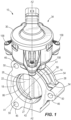
FIG. 1 is a perspective view of a valve assembly, such as an EGR valve assembly. -
FIG. 2 is a front elevation view of the valve assembly ofFIG. 1 . -
FIG. 3 is a rear elevation view of the valve assembly ofFIG. 1 , opposite the view ofFIG. 2 . -
FIG. 4 is a side view of the valve assembly ofFIG. 1 . -
FIG. 5 is an opposite side view of the valve assembly ofFIG. 1 . -
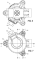
FIG. 6 is a bottom view of the valve assembly ofFIG. 1 . -
FIG. 7 is a top view of the valve assembly ofFIG. 1 . -
FIG. 8 is a front cross-sectional view of the valve assembly ofFIG. 1 , taken generally along the line A-A inFIG. 7 . -
FIG. 9 is a side cross-sectional view of the valve assembly ofFIG. 1 , taken generally along the line B-B inFIG. 7 . -
FIG. 10 is a top cross-sectional view of the valve assembly ofFIG. 1 , taken generally along the line C-C inFIG. 2 . -
FIG. 11A is an enlarged perspective view of a portion of the valve assembly ofFIG. 1 , illustrating a tapered end of a sealing member. -
FIG. 11B is an enlarged perspective view of another portion of the valve assembly ofFIG. 1 , illustrating an opposite tapered end of a sealing member shown inFIG. 11A . -
FIG. 12A is an enlarged perspective view of another portion of the valve assembly ofFIG. 1 , illustrating a tapered end of a sealing member. -
FIG. 12B is an enlarged perspective view of another portion of the valve assembly ofFIG. 1 , illustrating an opposite tapered end of a sealing member shown inFIG. 12A . -
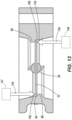
FIG. 13 is a schematic diagram of a method of manufacturing a valve assembly, such as the valve assembly ofFIG. 1 , illustrating a coining process. -
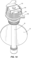
FIG. 14 is a perspective view of a portion of the valve assembly ofFIG. 1 , illustrating a spider assembly, a driven shaft, and a flap. -
FIG. 15 is an exploded view of the portion of the valve assembly shown inFIG. 14 . -
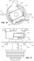
FIG. 16 is a top view of the spider assembly shown inFIG. 14 . -
FIG. 17 is a side view of the spider assembly and the driven shaft shown inFIG. 14 , with a torsion spring removed. -
FIG. 18 is a side view of the spider assembly and the driven shaft shown inFIG. 14 , with the spring and the spider member removed. -
FIG. 19 is another side view of the portion of the spider assembly and the driven shaft as shown inFIG. 18 . -
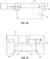
FIG. 20 is a side view of the spider member and a drive bowtie shown inFIG. 15 . -
FIG. 21 is a side view of the spider member, a driven bowtie, and a plate shown inFIG. 15 . -
FIG. 22 is a bottom view of the spider member shown inFIG. 15 . -
FIG. 23 is a top view of the spider member shown inFIG. 15 . -
FIG. 24 is a bottom view of the spider, the drive bowtie, and the plate shown inFIG. 21 . -
FIG. 25 is a perspective view of a valve housing portion of the valve assembly ofFIG. 1 . -
FIG. 26 is a top cross-sectional view of the valve assembly ofFIG. 1 , taken generally along the line D-D inFIG. 9 . -
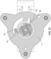
FIG. 27 is a top cross-sectional view of the valve assembly ofFIG. 1 , taken generally along the line E-E inFIG. 9 . -
FIG. 28 is a partial cross-sectional view of the valve assembly ofFIG. 1 , taken generally along the line F-F inFIG. 7 . -
FIG. 29 is a perspective view of a spring holder shown inFIG. 15 . -
FIG. 30 is a bottom perspective view of the valve assembly ofFIG. 1 , illustrated with the valve housing portion removed. - Before any independent embodiments are explained in detail, it is to be understood that the disclosure is not limited in its application to the details of construction and the arrangement of components set forth in the following description or illustrated in the following drawings. The disclosure is capable of other independent embodiments and of being practiced or of being carried out in various ways. Also, it is to be understood that the phraseology and terminology used herein is for the purpose of description and should not be regarded as limiting.
- Use of "including" and "comprising" and variations thereof as used herein is meant to encompass the items listed thereafter and equivalents thereof as well as additional items. Use of "consisting of" and variations thereof as used herein is meant to encompass only the items listed thereafter and equivalents thereof. Unless specified or limited otherwise, the terms "mounted," "connected," "supported," and "coupled" and variations thereof are used broadly and encompass both direct and indirect mountings, connections, supports, and couplings.
- Relative terminology, such as, for example, "about", "approximately", "substantially", etc., used in connection with a quantity or condition would be understood by those of ordinary skill to be inclusive of the stated value and has the meaning dictated by the context (for example, the term includes at least the degree of error associated with the measurement of, tolerances (e.g., manufacturing, assembly, use, etc.) associated with the particular value, etc.). Such terminology should also be considered as disclosing the range defined by the absolute values of the two endpoints. For example, the expression "from about 2 to about 4" also discloses the range "from 2 to 4". The relative terminology may refer to plus or minus a percentage (e.g., 1%, 5%, 10% or more) of an indicated value.
- Also, the functionality described herein as being performed by one component may be performed by multiple components in a distributed manner. Likewise, functionality performed by multiple components may be consolidated and performed by a single component. Similarly, a component described as performing particular functionality may also perform additional functionality not described herein. For example, a device or structure that is "configured" in a certain way is configured in at least that way but may also be configured in ways that are not listed.
- The embodiment(s) described below and illustrated in the figures are presented by way of example only and are not intended as a limitation upon the concepts and principles of the present disclosure. As such, it will be appreciated that variations and modifications to the elements and their configuration and/or arrangement exist within the spirit and scope of one or more independent aspects as described.
-
FIGS. 1-7 illustrate avalve assembly 10, such as an exhaust gas recirculation (EGR) valve assembly and, specifically, a cold-side EGR valve assembly, operable to control exhaust flow to the engine intake (not shown), thereby controlling the air-to-fuel ratio and reducing engine emissions. In other constructions (not shown), thevalve assembly 10 may be another type of valve assembly, for example, an exhaust brake valve assembly. - The
valve assembly 10 includes avalve housing portion 14 defining aflow passage 18 through which gas flows along a flow path. Abutterfly flap 22 is supported on a driven shaft 26 (at a flap end 27) for pivoting movement therewith between an open position, a closed position, in which gas flow is inhibited, and a plurality of intermediate flow positions. Anopposite transmission end 28 of the driven shaft 26 (seeFIG. 8 ) extends towards anactuator housing portion 30 in which a drive oractuator assembly 34 is housed. - With continued reference to
FIGS. 1-7 , thevalve housing portion 14 includes abody 38 having awall 42. Thewall 42 defines theflow passage 18 which extends along a passage axis A1. A plurality of bosses 46 (three shown), each having anopening 50, are circumferentially spaced apart on thebody 38. The illustratedopenings 50 are provided on a common circle and receive respective fasteners (not shown) for mounting theValve assembly 10 to an engine component such as an intake or exhaust manifold (not shown). - As shown in
FIG. 8 , abore 62, withportions flow passage 18, is defined in thevalve housing portion 14 in a direction transverse to thewall 42. The drivenshaft 26, extending along a driven shaft axis A2, is pivotably supported in thebore 62. -
FIGS. 9-10 illustrate aninner surface 66 of thewall 42 shaped to direct the flow of exhaust gases between opposite ports (e.g., aninlet 70 and an outlet 74). Anentrance surface 78 slopes inwardly from theinlet 70 toward theflap 22 and the drivenshaft 26, and anexit surface 82 slopes outwardly from theflap 22 and the drivenshaft 26 to theoutlet 74. In other constructions (not shown), theinner surface 66 may be at least partially cylindrical along the passage axis A1. - Additionally, the
inner surface 66 provides a surface against which theflap 22 is able to seal. With continued reference toFIGS. 9-10 , theinner surface 66 includes an annular first sealingridge 86 closer to theinlet 70 and an annularsecond sealing ridge 90 closer to theoutlet 74. Thefirst sealing ridge 86 has a sealingsurface 94 shaped to sealingly mate with a first portion of theflap 22, a radially-innerflat surface 98 and anopposite surface 102 sloped away from theflap 22 and the drivenshaft 26. Thefirst sealing surface 94 has an annular seal face area. - With continued reference to
FIGS. 9-10 , thesecond sealing ridge 90 includes a sealingsurface 106 shaped to sealingly mate with a second portion of theflap 22, a radially-innerflat surface 110 and anopposite surface 114 sloped away from theflap 22 and the drivenshaft 26. The sealingsurface 106 has an annular seal face area. The sealingridges flat surfaces opposite surfaces - With reference to
FIGS. 11A-12B , each sealingridge tapered end sloped end pointed end terminal end bore 62. - With continued reference to
FIG. 10 , a firstchamfered surface 126 transitions thesurface 102 into theinlet surface 78, and a secondchamfered surface 130 transitions thesurface 114 into theoutlet surface 82. A radially-outerflat surface 134 is positioned adjacent to thefirst sealing ridge 86 and surrounds a portion of theflap 22 when theflap 22 is in the closed position, and a radially-outerflat surface 138 is positioned adjacent to thesecond sealing ridge 90 and surrounds an opposite portion of theflap 22 when theflap 22 is in the closed position. A thirdchamfered surface 142 transitions theflat surface 134 to theoutlet surface 82, and a fourthchamfered surface 146 transitions theflat surface 138 to theinlet surface 78. - In operation, exhaust gases flow through the
inlet 70, along theflow passage 18, and through theoutlet 74. When theflap 22 is in the open position and, more particularly, in a fully open position, the flow is at a maximum. The exhaust gases flow over the sealingridges flap 22 and around the drivenshaft 26. When theflap 22 is in the closed position, theflap 22 engages the sealing surfaces 94, 106 to at least substantially block and prevent the flow of exhaust gases through theflow passage 18. - The exhaust gases may contain water vapor, particles, and other impurities. As exhaust gases flow through the
flow passage 18, deposits, such as condensate, "coke", "gunk", soot, and other matter may form on theinner surface 66. If deposits form on the sealingridges flap 22, the drivenshaft 26, thebore 62, etc., sealing efficiency and movement of theflap 22 and theshaft 26 may be inhibited. Sloped surfaces within the flow passage 18 (e.g., theopposite surfaces -
FIG. 13 schematically illustrates a process for coining theflap 22 and the sealing surfaces 94, 106 of thevalve assembly 10. Coining may provide avalve assembly 10 with aflap 22 having a precise, "custom" fit with the sealing surfaces 94, 106 as they have been formed in thevalve housing portion 14 and vice versa. - In the manufacturing process, the
flap 22 is supported on theshaft 26 in theflow passage 18 and engaged with the sealing surfaces 94, 106. Afirst ram 147 is inserted into theinlet 70 and pressed against afirst side 150 of theflap 22 opposite the sealingsurface 94, while asecond ram 148 is inserted into theoutlet 74 and pressed against asecond side 154 of theflap 22 opposite the sealingsurface 106. Therams force opposite sides flap 22 against thefirst sealing surface 94 and against thesecond sealing surface 106. As a result, theflap 22 conforms to contours of the sealing surfaces 94, 106, and vice versa. - With continued reference to
FIG. 13 , thefirst ram 147 has a first ram area, and thefirst sealing surface 94 defines a first seal face area. Thesecond ram 148 has a second ram area, and thesecond sealing surface 106 defines a second seal face area. In the illustrated construction, the first ram area is greater than the first seal face area, and the second ram area is greater than the second seal face area. - Each
force forces forces - With reference to
FIGS. 1 and8-9 , theactuator housing portion 30 is mounted to thevalve housing portion 14 byscrews 158. Theactuator assembly 34 includes an electric motor 162 (schematically illustrated; e.g., a brushless DC motor) positioned within theactuator housing portion 30. Anelectrical connector 166 provides electrical power and communication signals to themotor 162. Electrical and control components (not shown), such as, for example, a controller (including an electronic processor), a motor controller, a printed circuit board, one or more sensors, etc., are also housed in theactuator housing portion 30. - The
electric motor 162 includes a pivotingdrive shaft 170 defining a drive shaft axis A3. In some embodiments, the drive shaft axis A3 not be collinear with the driven shaft axis A2. A spider assembly 174 (seeFIGS. 8 and14-15 ) drivingly connects thedrive shaft 170 to the drivenshaft 26 and may accommodate misalignment between the axes A2, A3. Thespider assembly 174 generally includes (seeFIGS. 14-15 ) adrive bowtie 178, a drivenbowtie 182, aplate 186, aspider member 190, atorsion spring 194, and aspring holder 196. - As shown in
FIGS. 14-19 , thedrive bowtie 178 defines anopening 198 proximate its center for coupling to thedrive shaft 170. The drivenbowtie 182 defines anopening 202 proximate its center for coupling to the drivenshaft 26. In other constructions (not shown), thebowties shafts - With reference to
FIGS. 14-24 , thespider member 190 defines afirst slot 206 configured to receive and allow sliding movement of thedrive bowtie 178 along theslot 206 while restraining transverse movement of thebowtie 178. Similarly, thespider member 190 defines asecond slot 210 configured and allow sliding movement of the drivenbowtie 182 along theslot 210 while restraining transverse movement of thebowtie 182. In the illustrated construction, theslots bowtie bowties respective shafts - As shown in
FIG. 21 , opposedslots second slot 210, are configured to receive theplate 186 and retain the drivenbowtie 182 in theslot 210. Theplate 186 defines an opening receiving the drivenshaft 26. Thespider member 190 defines anaxial opening 218 at least roughly aligned withshafts - As shown in
FIG. 22 , thespider member 190 includes circumferentially-spacedprotrusions spider member 190 near thefirst slot 206. Theprotrusion 222 defines anotch 234 facing toward the drivenshaft 26. - With reference to
FIGS. 25-28 , thevalve housing portion 14 defines afirst recess 238 and asecond recess 242 spaced circumferentially with respect to the driven shaft axis A2. Thefirst recess 238 has a depth D1 (FIG. 28 ) and a width W1 (FIG. 26 ) and subtends an angle α1 (FIG. 27 ). The angle α1 may be greater than about 45° and less than about 135° and, more particularly, approximately equal to a quarter-turn (e.g., about 70°, as shown). Thesecond recess 242 is a notch having a depth D2 (FIG. 28 ) and a width W2 (FIG. 26 ; e.g., about 6 millimeters (mm)) sufficient to constrain theend 258 of thespring 194, as discussed below. - A
spring bearing surface 246 is defined on an interior side of the second recess 242 (e.g., on a clockwise side of thesecond recess 242 when viewed inFIGS. 26-27 ). Aledge 250 circumferentially surrounds thebore 62 and faces towards theactuator housing portion 30. - The
spring 194 interfaces between thespider member 190 and thevalve housing portion 14 in order to pivotably bias thespider assembly 174 and, more specifically, thespider member 190, the drivenbowtie 182, and the drivenshaft 26, in a direction corresponding to the closed position of theflap 22. As shown inFIG. 27 , afirst end 254 of thespring 194 engages the spider member 190 (e.g., engaging within thenotch 234 in the first protrusion 222), and asecond end 258 engages the valve housing portion 14 (e.g., within thesecond recess 242, bearing against the spring bearing surface 246). Thespring 194 biases thespider member 190 and, therefore, thespider assembly 174, in a counterclockwise direction (when viewed inFIG. 27 ). Thespring 194 is configured to bias theflap 22 into the closed position (as mentioned above) and to take up (that is, inhibit or eliminate) lash in thespider assembly 174. - With reference to
FIGS. 8 and26 , thespring holder 196 is positioned between theledge 250 and thespring 194. The illustratedspring holder 196 is formed of austenitic steel, which may provide, for example, friction reduction, reduced debris creation, compatibility with material of thespring 194, etc. - The
spring holder 196 includes (seeFIG. 29 ) a generally flat andcircumferential flange 266 from which centeringprojections projections flange 266 and extend into thebore 62 when thespring holder 196 is positioned in thevalve housing portion 14. - A
spring positioning projection 274 protrudes from theflange 266 in a direction opposite to the centeringprojections spring positioning projection 274 is oriented at approximately 90° relative to theflange 266 and engages an inner surface of thespring 194 when thespring holder 196 is in position in thespider assembly 174 to position thespring 194 relative to thespring holder 196 and relative to thevalve housing portion 14. An orientingprojection 278 extends radially from theflange 266 and, as illustrated, is configured (e.g., sized, shaped, etc.) to fit within thesecond recess 242 of thevalve housing portion 14 to orient thespring holder 196 relative to thevalve housing portion 14. - With reference to
FIGS. 8-9 and30 , aseal 282 is positioned between thevalve housing portion 14 and theactuator housing portion 30. The illustratedseal 282 is an O-ring and fits withinrespective grooves valve housing portion 14 and in theactuator housing portion 30. Theseal 282 is configured to inhibit the ingress of dust, dirt, debris, gas, and other material. - In operation of the
valve assembly 10, control signals are provided (e.g., to the controller) to control theactuator assembly 34 to position theflap 22 in a desired position in theflow passage 18 for a desired flow of gas through theflow passage 18. Themotor 162 pivots thedrive shaft 170, causing pivoting movement of thedrive bowtie 178 and thespider member 190 against the biasing force of thespring 194. Pivoting movement of thespider member 190 causes pivoting movement of the drivenbowtie 182, the drivenshaft 26, and theflap 22. The range of motion of theflap 22 is limited by the extent of the angle α1 and a width of thefirst protrusion 222. - As mentioned above, the driven shaft axis A2 and the drive shaft axis A3 may be misaligned. The
spider assembly 174 is configured to transmit torque from thedrive shaft 170 to theflap 22 despite a misalignment between the axes A2, A3. If the axes, A2, A3 are misaligned, as thedrive bowtie 178 pivots, thedrive bowtie 178 may simultaneously slide along thefirst slot 206. Similarly, as thespider member 190 pivots with thedrive bowtie 178, the drivenbowtie 182 pivots and may also simultaneously slide along thesecond slot 210. The sliding movement of thebowties shafts - Manufacturing tolerances may exist between the drive and driven components. As a result, a certain amount of lash could exist within the
spider assembly 174, which could inhibitshafts spring 194 biases the components (e.g., to a position corresponding to the closed position of the flap 22) to compensate for the lash. In other constructions (not shown), thespider assembly 174 may be used in other shaft arrangements (e.g., between a different type of drive shaft and driven shaft) to, for example, accommodate misalignment of the shafts, take up lash, etc. - Although the invention has been described in detail with reference to certain preferred embodiments, variations and modifications exist within the scope and spirit of one or more independent aspects of the invention as described above. The embodiment(s) described above and illustrated in the figures are presented by way of example only and are not intended as a limitation upon the concepts and principles of the present disclosure. As such, it will be appreciated that variations and modifications to the elements and their configuration and/or arrangement exist within the spirit and scope of one or more independent aspects as described.
- One or more independent features and/or independent advantages of the invention may be set forth in the claims.
Claims (15)
- An exhaust gas recirculation (EGR) valve assembly comprising:a valve housing including a body with a wall defining a flow passage along a flow path between an inlet and an outlet, the valve housing further defining a bore communicating with the flow passage and extending transverse to the flow path;a shaft supported in the bore and extending into the flow passage;a flap supported on the shaft in the flow passage, the flap being movable relative to the flow passage between a closed position and an open position; anda sealing member projecting from the wall into the flow path, the sealing member having a sealing surface configured to interact with the flap in the closed position to inhibit gas flow through the flow passage, an opposite surface facing away from the sealing surface and tapering toward the wall, and a circumferential end surface proximate the bore, the end surface being tapered away from the bore.
- The exhaust gas recirculation (EGR) valve assembly of claim 1, wherein the sealing member is a first sealing member, the sealing surface is a first sealing surface configured to interact with a first portion of the flap, the opposite surface is a first opposite surface, and the end surface is a first sealing member end surface, and wherein the exhaust gas recirculation (EGR) valve assembly further comprises a second sealing member positioned between the inlet and the outlet, the second sealing member having a second sealing surface configured to interact with a second portion of the flap in the closed position to inhibit gas flow through the flow passage, a second opposite surface facing away from the second sealing surface and tapering toward the wall, and a circumferential second sealing member end surface proximate the bore, the second sealing member end surface being tapered away from the bore.
- The exhaust gas recirculation (EGR) valve assembly of claim 2, wherein the bore is a first bore, wherein the valve housing defines a second bore spaced from the first bore, the shaft being supported in the first bore and the second bore, wherein the first sealing member has opposite first sealing member end surfaces, one opposite first sealing member end surface being proximate and tapering away from the first bore, and another opposite first sealing member end surface being proximate and tapering away from the second bore, and wherein the second sealing member has opposite second sealing member end surfaces, one opposite second sealing member end surface being proximate and tapering away from the first bore, and another opposite second sealing member end surface being proximate and tapering away from the second bore.
- The exhaust gas recirculation (EGR) valve assembly of claim 3, including one or more of the following features:(i) wherein the first opposite surface extends between the opposite first sealing member end surfaces, and wherein the second opposite surface extends between the opposite second sealing member end surfaces; or(ii) wherein the first portion of the flap is coined against the first sealing surface, and wherein the second portion of the flap is coined against the second sealing surface.
- The exhaust gas recirculation (EGR) valve assembly of claim 1, wherein the bore is a first bore, wherein the valve housing defines a second bore spaced from the first bore, the shaft being supported in the first bore and the second bore, wherein the sealing member has opposite end surfaces, one opposite end surface being proximate and tapering away from the first bore, and another opposite end surface being proximate and tapering away from the second bore, optionally
wherein the opposite surface extends between the opposite end surfaces. - The exhaust gas recirculation (EGR) valve assembly of claim 1, including one or more of the following features:(i) wherein the flap is coined against the sealing surface with a force greater than about 4,000 pound-force (Ibf); or(ii) further comprising an actuator assembly including a drive shaft extending along and pivotable about a drive axis, wherein a spider assembly is configured to drivingly connect the drive shaft to the shaft, the spider assembly including:a spider member defining a first slot facing toward the drive shaft and extending along a first slot axis and a second slot facing toward the shaft and extending along second slot axis, the second slot axis being transverse to the first slot axis,a first sliding member connectable to the drive shaft and positionable in the first slot, the first sliding member being configured to slide in the first slot and along the first slot axis, anda second sliding member connectable to the shaft and positionable in the second slot, the second sliding member being configured to slide in the second slot and along the second slot axis.
- A method of manufacturing an exhaust gas recirculation (EGR) valve assembly, the valve assembly including a valve housing with a body having a wall defining a flow passage along a flow path between an inlet and an outlet, a flap supported in the flow passage for movement between a closed position and an open position, a first sealing member projecting from the wall into the flow path, the first sealing member having a first sealing surface configured to interact with a first portion of the flap in the closed position to inhibit gas flow through the flow passage, and a second sealing member projecting from the wall into the flow path, the second sealing member having a second sealing surface configured to interact with a second portion of the flap in the closed position to inhibit gas flow through the flow passage, the method comprising:supporting the flap in the flow passage with the first portion of the flap engaging the first sealing surface and the second portion of the flap engaging the second sealing surface;engaging, through the inlet, a first ram against a side of the first portion of the flap opposite the first sealing surface;engaging, through the outlet, a second ram against a side of the second portion of the flap opposite the second sealing surface; andsimultaneously applying, with the first ram and the second ram, force to the flap to coin the first portion of the flap against the first sealing surface and to coin the second portion of the flap against the second sealing surface.
- The method of claim 7, wherein applying includes applying, with the first ram and the second ram, a force greater than about 4,000 lbf, optionally
wherein applying includes applying, with the first ram and the second ram, a force up to about 12,000 lbf. - The method of claim 7, including one or more of the following features:(i) wherein applying includes applying, with the first ram and the second ram, a force greater than about 7,000 lbf and up to about 9,000 lbf; or(ii) wherein applying includes applying, with each the first ram and the second ram, a substantially equal force.
- The method of claim 7, wherein the first ram has a first ram area, wherein the first sealing surface defines a first seal face area, and wherein the first ram area is greater than the first seal face area, optionallywherein the second ram has a second ram area, wherein the second sealing surface defines a second seal face area, and wherein the second ram area is greater than the second seal face area, optionallywherein the first seal face area is annular, and wherein the second seal face area is annular.
- An exhaust gas recirculation (EGR) valve assembly comprising:a valve housing including a body with a wall defining a flow passage along a flow path between an inlet and an outlet;a shaft supported by the valve housing and extending into the flow passage, the shaft extending along and being pivotable about a shaft axis;a flap supported on the shaft in the flow passage, the flap being movable relative to the flow passage between a closed position, in which flow of gas through the flow passage is inhibited, and an open position;an actuator assembly including a drive shaft extending along and pivotable about a drive axis; anda spider assembly configured to drivingly connect the drive shaft and the shaft, the spider assembly including:a spider member defining a first slot facing toward the drive shaft and extending along a first slot axis and a second slot facing toward the shaft and extending along second slot axis, the second slot axis being transverse to the first slot axis,a first sliding member connectable to the drive shaft and positionable in the first slot, the first sliding member being configured to slide in the first slot and along the first slot axis, anda second sliding member connectable to the shaft and positionable in the second slot, the second sliding member being configured to slide in the second slot and along the second slot axis.
- The exhaust gas recirculation (EGR) valve assembly of claim 11, further comprising a torsion spring engageable between the valve housing and the spider member and configured to bias the flap toward the closed position.
- The exhaust gas recirculation (EGR) valve assembly of claim 12, wherein the spider member includes a protrusion defining a notch, the torsion spring having an end engaging the notch, optionally
wherein the valve housing defines a first recess and a second recess, wherein the protrusion extends into the first recess, and wherein the end of the torsion spring is a first end, and the torsion spring has a second end extending into the second recess. - The exhaust gas recirculation (EGR) valve assembly of claim 12, wherein the valve housing defines a bore and has an annular ledge extending about at least a portion of the bore and facing towards the spider member, wherein the shaft is positioned in the bore, and wherein the exhaust gas recirculation (EGR) valve assembly further comprises a spring holder positioned between the ledge and the torsion spring, optionally including one or more of the following features:(i) wherein the spring holder defines an opening, the shaft extending through the opening; or(ii) wherein the spring holder has a flange positioned between the ledge and the torsion spring, the spring holder also having, extending from the flange, a radially-extending orienting projection engaging a recess defined by the valve housing, an axially-extending centering projection positioned in the bore, and an axially-extending spring positioning projection engaging the torsion spring.
- The exhaust gas recirculation (EGR) valve assembly of claim 11, further comprising:a bore, wherein the shaft is positioned in the bore; anda sealing member projecting from the wall into the flow path, the sealing member having a sealing surface configured to interact with the flap in the closed position to inhibit gas flow through the flow passage, an opposite surface facing away from the sealing surface and tapering toward the wall, and a circumferential end surface proximate the bore, the end surface being tapered away from the bore, optionallywherein the flap is coined against the sealing surface with a force greater than about 4,000 lbf.
Priority Applications (1)
| Application Number | Priority Date | Filing Date | Title |
|---|---|---|---|
| EP25156687.3A EP4528095A3 (en) | 2023-02-17 | 2024-01-31 | Exhaust gas recirculation valve assembly |
Applications Claiming Priority (1)
| Application Number | Priority Date | Filing Date | Title |
|---|---|---|---|
| US202363485725P | 2023-02-17 | 2023-02-17 |
Related Child Applications (1)
| Application Number | Title | Priority Date | Filing Date |
|---|---|---|---|
| EP25156687.3A Division EP4528095A3 (en) | 2023-02-17 | 2024-01-31 | Exhaust gas recirculation valve assembly |
Publications (2)
| Publication Number | Publication Date |
|---|---|
| EP4417809A2 true EP4417809A2 (en) | 2024-08-21 |
| EP4417809A3 EP4417809A3 (en) | 2024-12-04 |
Family
ID=89771996
Family Applications (2)
| Application Number | Title | Priority Date | Filing Date |
|---|---|---|---|
| EP24155111.8A Pending EP4417809A3 (en) | 2023-02-17 | 2024-01-31 | Exhaust gas recirculation valve assembly |
| EP25156687.3A Pending EP4528095A3 (en) | 2023-02-17 | 2024-01-31 | Exhaust gas recirculation valve assembly |
Family Applications After (1)
| Application Number | Title | Priority Date | Filing Date |
|---|---|---|---|
| EP25156687.3A Pending EP4528095A3 (en) | 2023-02-17 | 2024-01-31 | Exhaust gas recirculation valve assembly |
Country Status (3)
| Country | Link |
|---|---|
| US (1) | US12392309B2 (en) |
| EP (2) | EP4417809A3 (en) |
| CN (1) | CN118517357A (en) |
Family Cites Families (60)
| Publication number | Priority date | Publication date | Assignee | Title |
|---|---|---|---|---|
| US5531205A (en) | 1995-03-31 | 1996-07-02 | Siemens Electric Limited | Rotary diesel electric EGR valve |
| US6178956B1 (en) | 1996-05-20 | 2001-01-30 | Borgwarner Inc. | Automotive fluid control system with pressure balanced solenoid valve |
| US6681799B2 (en) | 2001-09-21 | 2004-01-27 | Siemens Vdo Automotive, Inc. | Exhaust gas regulator including an overmolded housing |
| US6598619B2 (en) | 2001-09-21 | 2003-07-29 | Siemens Vdo Automotive, Inc. | Exhaust gas regulator including a resilient coupling |
| US6698717B1 (en) * | 2002-10-24 | 2004-03-02 | Honeywell International Inc. | Modified butterfly valve and assembly |
| JP4285267B2 (en) * | 2004-02-19 | 2009-06-24 | 株式会社デンソー | Exhaust gas recirculation device |
| JP4383933B2 (en) | 2004-03-15 | 2009-12-16 | 三菱電機株式会社 | Method for manufacturing output shaft connection structure of electric control valve |
| DE102005033997A1 (en) | 2005-07-21 | 2007-01-25 | Gustav Wahler Gmbh U. Co. Kg | Control valve used as exhaust gas re-circulating valve comprises valve part formed from tubular body which is arranged at axial height of outlet openings and across longitudinal progression of cylindrical valve chamber |
| DE102006048678B4 (en) | 2006-10-14 | 2011-11-17 | Pierburg Gmbh | coupling device |
| US7536990B2 (en) | 2006-11-21 | 2009-05-26 | Emcon Technologies Llc | Hybrid exhaust valve assembly |
| KR101057066B1 (en) | 2008-02-04 | 2011-08-16 | 캄텍주식회사 | Automotive Easy Valve |
| US20110031425A1 (en) | 2008-04-07 | 2011-02-10 | G. W. Lisk Company, Inc. | Motor operated butterfly valve |
| DE102008050466B4 (en) | 2008-10-04 | 2021-01-28 | BorgWarner Esslingen GmbH | Valve device for controlling an exhaust gas flow |
| DE102009013815B4 (en) | 2009-03-18 | 2016-09-22 | Friedrich Boysen Gmbh & Co. Kg | Valve device |
| DE102009016597C5 (en) | 2009-04-08 | 2023-03-23 | Küster Holding GmbH | Exhaust flap drive for a motor vehicle |
| US8434736B2 (en) | 2010-09-28 | 2013-05-07 | Keihin Corporation | Fluid passage valve |
| DE102011107088C5 (en) | 2011-07-11 | 2019-10-02 | Friedrich Boysen Gmbh & Co. Kg | Valve device |
| DE102013103105B4 (en) | 2013-03-26 | 2015-06-25 | Smk Systeme Metall Kunststoff Gmbh & Co. Kg. | Exhaust flap for an automobile |
| DE102014017523A1 (en) | 2013-11-30 | 2015-06-03 | Kohlhage Automotive GmbH & Co. KG | Valve unit, such as exhaust flap unit for motor vehicles |
| DE102014113332B3 (en) | 2014-09-16 | 2015-11-05 | Smk Systeme Metall Kunststoff Gmbh & Co. Kg. | Valve device |
| DE102014118492B4 (en) | 2014-12-12 | 2020-05-14 | Tenneco Gmbh | Exhaust valve actuator |
| FR3032253B1 (en) | 2015-02-04 | 2017-01-20 | Mmt Sa | ELECTRO-CONTROLLED VALVE FOR HOT FLUID |
| DE102015202211B4 (en) | 2015-02-09 | 2017-06-01 | smk systeme metall kunststoff gmbh & co. kg | Flap device for a motor vehicle |
| DE102015104287B4 (en) | 2015-03-23 | 2018-02-01 | BorgWarner Esslingen GmbH | Valve for an exhaust system of an internal combustion engine |
| ES2686738T3 (en) | 2015-09-14 | 2018-10-19 | Bosal Emission Control Systems Nv | Valve unit that includes a mechanical coupler |
| DE102015222609B4 (en) | 2015-11-17 | 2022-05-25 | Purem GmbH | Electric exhaust flap device, silencer and exhaust system |
| DE102016104102A1 (en) | 2016-03-07 | 2017-09-07 | Faurecia Emissions Control Technologies, Germany Gmbh | Drive for an exhaust flap |
| DE102016203794B4 (en) | 2016-03-09 | 2019-03-14 | smk systeme metall kunststoff gmbh & co. kg | Flap valve with axial projection bearing |
| FR3049673B1 (en) * | 2016-03-30 | 2018-11-23 | Faurecia Systemes D'echappement | EXHAUST LINE VALVE AND CORRESPONDING MOUNTING METHOD |
| JP6753694B2 (en) | 2016-05-17 | 2020-09-09 | 株式会社ミクニ | Valve device |
| DE102016114703A1 (en) | 2016-06-28 | 2017-12-28 | Eberspächer Exhaust Technology GmbH & Co. KG | Coupling arrangement for rotational coupling of a pivot shaft of a valve cover of an exhaust valve with a drive member |
| DE102016114704A1 (en) | 2016-07-05 | 2018-01-11 | Eberspächer Exhaust Technology GmbH & Co. KG | Coupling arrangement for rotational coupling of a pivot shaft of a valve cover of an exhaust valve with a drive member |
| DE102016112694A1 (en) | 2016-07-11 | 2018-01-11 | Faurecia Emissions Control Technologies, Germany Gmbh | Valve actuator |
| US10060311B2 (en) | 2016-08-17 | 2018-08-28 | Hyundai Motor Company | Electric valve |
| DE102016223444B3 (en) | 2016-11-25 | 2018-05-24 | smk systeme metall kunststoff gmbh & co. kg | Optimized flap valve for an exhaust flap system and manufacturing method therefor |
| EP3366904B1 (en) | 2017-02-22 | 2019-10-16 | Bosal Emission Control Systems NV | Valve unit including an interface |
| CN210769043U (en) | 2017-04-11 | 2020-06-16 | 富尔西亚排气系统公司 | Valve and exhaust gas line having such valve |
| DE102017127740A1 (en) | 2017-11-23 | 2019-05-23 | Eberspächer Exhaust Technology GmbH & Co. KG | adjustable flap |
| FR3074536B1 (en) | 2017-12-06 | 2020-11-20 | Faurecia Systemes Dechappement | EXHAUST LINE VALVE WITH EASY COUPLING BETWEEN THE ACTUATOR AND THE SHUTTER, AND ASSEMBLY METHOD OF SUCH A VALVE |
| DE102017222465B4 (en) | 2017-12-12 | 2021-05-06 | smk systeme metall kunststoff gmbh & co. kg | Flap device for the exhaust system of an internal combustion engine |
| FR3080426B1 (en) | 2018-04-24 | 2020-04-03 | Faurecia Systemes D'echappement | METHOD OF ASSEMBLING A VALVE FOR AN EXHAUST LINE AND CORRESPONDING VALVE |
| FR3080427B1 (en) | 2018-04-24 | 2020-04-03 | Faurecia Systemes D'echappement | VALVE FOR AN EXHAUST LINE |
| FR3084415B1 (en) | 2018-07-30 | 2021-11-26 | Faurecia Systemes Dechappement | MECHANICAL COUPLING ASSEMBLY, ESPECIALLY FOR BUTTERFLY VALVE OF EXHAUST SYSTEM |
| FR3084709B1 (en) | 2018-08-02 | 2021-09-03 | Faurecia Systemes Dechappement | ROTATIONAL COUPLING |
| KR102634448B1 (en) | 2018-08-13 | 2024-02-07 | 현대자동차주식회사 | Variable exhaust valve for vehicle |
| DE102018123400A1 (en) | 2018-09-24 | 2020-03-26 | Eberspächer Exhaust Technology GmbH & Co. KG | Exhaust flap |
| DE102018123403A1 (en) | 2018-09-24 | 2020-03-26 | Eberspächer Exhaust Technology GmbH & Co. KG | Exhaust flap |
| DE102019103556A1 (en) | 2019-02-13 | 2020-08-13 | Eberspächer Exhaust Technology GmbH & Co. KG | Exhaust flap |
| DE102019104018A1 (en) | 2019-02-18 | 2020-08-20 | Friedrich Boysen Gmbh & Co. Kg | FLAP DEVICE |
| DE202019102211U1 (en) | 2019-04-17 | 2019-07-22 | Faurecia Systemes D'echappement | Controlled valve for an exhaust pipe |
| FR3097290B1 (en) | 2019-06-17 | 2021-09-17 | Faurecia Systemes Dechappement | Anti-knock exhaust valve |
| DE102020103420A1 (en) | 2020-02-11 | 2021-08-12 | Friedrich Boysen GmbH & Co KG. | Flap device |
| JP2021127739A (en) | 2020-02-14 | 2021-09-02 | 株式会社ミクニ | Vehicle exhaust valve device |
| JP7393239B2 (en) | 2020-02-14 | 2023-12-06 | 株式会社ミクニ | vehicle exhaust valve device |
| DE102020118355A1 (en) | 2020-07-13 | 2022-01-13 | Purem GmbH | exhaust flap |
| DE102020118356A1 (en) | 2020-07-13 | 2022-01-13 | Purem GmbH | exhaust flap |
| EP4008892A1 (en) | 2020-12-02 | 2022-06-08 | Akrapovic d.d. | Coupling device, valve system and method for assembling a coupling device or a valve system |
| DE102021101134A1 (en) | 2021-01-20 | 2022-07-21 | Purem GmbH | coupling arrangement |
| DE102021101135A1 (en) | 2021-01-20 | 2022-07-21 | Purem GmbH | coupling arrangement |
| IT202100004703A1 (en) | 2021-03-01 | 2022-09-01 | Marelli Europe Spa | MOTORIZED BUTTERFLY VALVE FOR AN EXHAUST LINE |
-
2024
- 2024-01-18 US US18/416,117 patent/US12392309B2/en active Active
- 2024-01-31 EP EP24155111.8A patent/EP4417809A3/en active Pending
- 2024-01-31 EP EP25156687.3A patent/EP4528095A3/en active Pending
- 2024-02-06 CN CN202410169621.6A patent/CN118517357A/en active Pending
Also Published As
| Publication number | Publication date |
|---|---|
| US12392309B2 (en) | 2025-08-19 |
| CN118517357A (en) | 2024-08-20 |
| US20240280071A1 (en) | 2024-08-22 |
| EP4528095A2 (en) | 2025-03-26 |
| EP4417809A3 (en) | 2024-12-04 |
| EP4528095A3 (en) | 2025-06-04 |
Similar Documents
| Publication | Publication Date | Title |
|---|---|---|
| CN100387814C (en) | Exhaust gas recirculation device with butterfly valve | |
| EP1529952B1 (en) | Electronic EGR gas control system | |
| EP2156023B1 (en) | Valve module for a combustion engine breathing system | |
| KR20190073485A (en) | Valve device | |
| EP1869308B1 (en) | Egr valve having rest position | |
| US7472886B2 (en) | Fluid control valve | |
| US20070144483A1 (en) | Valve assembly having a sealing member | |
| CN101568711A (en) | Air valve and method of use | |
| US6997163B2 (en) | Throttle control apparatus having internally supporting structure | |
| JP2011058536A (en) | Fluid control valve and manufacturing method thereof | |
| EP1544438A2 (en) | Supporting device for actuator received in housing | |
| EP2085601B1 (en) | Exhaust gas recirculation valve for vehicle | |
| US10473232B2 (en) | Split linkage mechanism for valve assembly | |
| EP4417809A2 (en) | Exhaust gas recirculation valve assembly | |
| EP2042708A1 (en) | Butterfly valve for an internal combustion engine | |
| US7204240B2 (en) | Integrated valve | |
| US8342148B2 (en) | Throttle valve for internal combustion engine | |
| US8434736B2 (en) | Fluid passage valve | |
| WO2018100872A1 (en) | Valve device | |
| US6196178B1 (en) | Air intake apparatus for internal combustion engine | |
| JP4793290B2 (en) | Fluid control valve | |
| US20210172370A1 (en) | Wastegate assembly and turbocharger including the same | |
| JP2008095924A (en) | Sealing device | |
| US20240280177A1 (en) | Valve assembly and method | |
| CN114402123A (en) | Valve timing control device for internal combustion engine |
Legal Events
| Date | Code | Title | Description |
|---|---|---|---|
| PUAI | Public reference made under article 153(3) epc to a published international application that has entered the european phase |
Free format text: ORIGINAL CODE: 0009012 |
|
| STAA | Information on the status of an ep patent application or granted ep patent |
Free format text: STATUS: THE APPLICATION HAS BEEN PUBLISHED |
|
| AK | Designated contracting states |
Kind code of ref document: A2 Designated state(s): AL AT BE BG CH CY CZ DE DK EE ES FI FR GB GR HR HU IE IS IT LI LT LU LV MC ME MK MT NL NO PL PT RO RS SE SI SK SM TR |
|
| PUAL | Search report despatched |
Free format text: ORIGINAL CODE: 0009013 |
|
| AK | Designated contracting states |
Kind code of ref document: A3 Designated state(s): AL AT BE BG CH CY CZ DE DK EE ES FI FR GB GR HR HU IE IS IT LI LT LU LV MC ME MK MT NL NO PL PT RO RS SE SI SK SM TR |
|
| RIC1 | Information provided on ipc code assigned before grant |
Ipc: F02M 26/70 20160101AFI20241025BHEP |
|
| STAA | Information on the status of an ep patent application or granted ep patent |
Free format text: STATUS: REQUEST FOR EXAMINATION WAS MADE |
|
| 17P | Request for examination filed |
Effective date: 20250206 |
|
| STAA | Information on the status of an ep patent application or granted ep patent |
Free format text: STATUS: EXAMINATION IS IN PROGRESS |
|
| 17Q | First examination report despatched |
Effective date: 20251112 |