EP4415328A2 - Commutation dynamique entre des noeuds périphériques dans un système de réseau autonome - Google Patents
Commutation dynamique entre des noeuds périphériques dans un système de réseau autonome Download PDFInfo
- Publication number
- EP4415328A2 EP4415328A2 EP24185908.1A EP24185908A EP4415328A2 EP 4415328 A2 EP4415328 A2 EP 4415328A2 EP 24185908 A EP24185908 A EP 24185908A EP 4415328 A2 EP4415328 A2 EP 4415328A2
- Authority
- EP
- European Patent Office
- Prior art keywords
- node
- edge node
- autonomous system
- edge
- address
- Prior art date
- Legal status (The legal status is an assumption and is not a legal conclusion. Google has not performed a legal analysis and makes no representation as to the accuracy of the status listed.)
- Pending
Links
Images


Classifications
-
- H—ELECTRICITY
- H04—ELECTRIC COMMUNICATION TECHNIQUE
- H04L—TRANSMISSION OF DIGITAL INFORMATION, e.g. TELEGRAPHIC COMMUNICATION
- H04L45/00—Routing or path finding of packets in data switching networks
- H04L45/302—Route determination based on requested QoS
-
- H—ELECTRICITY
- H04—ELECTRIC COMMUNICATION TECHNIQUE
- H04L—TRANSMISSION OF DIGITAL INFORMATION, e.g. TELEGRAPHIC COMMUNICATION
- H04L45/00—Routing or path finding of packets in data switching networks
- H04L45/02—Topology update or discovery
- H04L45/04—Interdomain routing, e.g. hierarchical routing
-
- H—ELECTRICITY
- H04—ELECTRIC COMMUNICATION TECHNIQUE
- H04L—TRANSMISSION OF DIGITAL INFORMATION, e.g. TELEGRAPHIC COMMUNICATION
- H04L41/00—Arrangements for maintenance, administration or management of data switching networks, e.g. of packet switching networks
- H04L41/12—Discovery or management of network topologies
-
- H—ELECTRICITY
- H04—ELECTRIC COMMUNICATION TECHNIQUE
- H04L—TRANSMISSION OF DIGITAL INFORMATION, e.g. TELEGRAPHIC COMMUNICATION
- H04L43/00—Arrangements for monitoring or testing data switching networks
- H04L43/16—Threshold monitoring
-
- H—ELECTRICITY
- H04—ELECTRIC COMMUNICATION TECHNIQUE
- H04L—TRANSMISSION OF DIGITAL INFORMATION, e.g. TELEGRAPHIC COMMUNICATION
- H04L45/00—Routing or path finding of packets in data switching networks
- H04L45/42—Centralised routing
-
- H—ELECTRICITY
- H04—ELECTRIC COMMUNICATION TECHNIQUE
- H04L—TRANSMISSION OF DIGITAL INFORMATION, e.g. TELEGRAPHIC COMMUNICATION
- H04L45/00—Routing or path finding of packets in data switching networks
- H04L45/74—Address processing for routing
-
- H—ELECTRICITY
- H04—ELECTRIC COMMUNICATION TECHNIQUE
- H04W—WIRELESS COMMUNICATION NETWORKS
- H04W76/00—Connection management
- H04W76/10—Connection setup
-
- H—ELECTRICITY
- H04—ELECTRIC COMMUNICATION TECHNIQUE
- H04L—TRANSMISSION OF DIGITAL INFORMATION, e.g. TELEGRAPHIC COMMUNICATION
- H04L43/00—Arrangements for monitoring or testing data switching networks
- H04L43/10—Active monitoring, e.g. heartbeat, ping or trace-route
-
- H—ELECTRICITY
- H04—ELECTRIC COMMUNICATION TECHNIQUE
- H04L—TRANSMISSION OF DIGITAL INFORMATION, e.g. TELEGRAPHIC COMMUNICATION
- H04L61/00—Network arrangements, protocols or services for addressing or naming
- H04L61/09—Mapping addresses
- H04L61/25—Mapping addresses of the same type
- H04L61/2503—Translation of Internet protocol [IP] addresses
Definitions
- the present disclosure relates generally to the field of network traffic routing, and, more specifically, to the field of routing across multiple autonomous systems.
- An autonomous system refers to a network or a collection of networks that are administrated by a single entity or organization, e.g., an Internet service provider (ISP).
- ISP Internet service provider
- an autonomous system is a heterogeneous network having many subnetworks with combined routing logic and common routing policies.
- An autonomous system usually uses multiple ingress and egress edge nodes to interface with other autonomous system. Outbound data traffic of the autonomous system goes through a designated egress edge node to reach the destination node in another autonomous system.
- Border Gateway Protocol is a standardized exterior gateway protocol designed to exchange routing and reachability information among autonomous systems on the Internet.
- the BGP is used to make routing decisions based on paths, network policies or rule-sets configured by a network administrator, and is involved in making core routing decisions.
- the BGP may also be used for routing within an autonomous system or across multiple autonomous systems.
- an autonomous typically assigns a subnetwork or a set of associated network addresses to a specific edge node and broadcasts the assignment to all the coupled external autonomous systems according to the BGP.
- the assignment may result from a routing optimization process.
- the data transmission is routed through an assigned edge node.
- the information of one autonomous system that is needed for routing determination is not readily available to another autonomous system, including a reassignment of the egress edge nodes. If the autonomous system switches to using another egress edge node for a particular subnetwork to improve network performance, the change has to be communicated to another autonomous system through broadcast again. Otherwise, inbound data traffic from another autonomous system still goes through the originally assigned edge node to reach the particular subnetwork. This makes the change of edge node ineffective in terms of network performance improvement.
- Broadcasting an edge node selection in an autonomous system is usually directed to all the external autonomous systems. Frequent broadcasting is undesirable as it contributes to network traffic congestion.
- network performance is usually specific to a particular external autonomous system or a particular link.
- broadcasting the reassignment of the involved subnetwork to another edge node causes a substantial amount traffic that is unrelated to the particular external antonymous system or link to migrate to the selected edge node as well. Inevitably, this further counteracts the overall effect in network performance improvement.
- a first edge node may be used for routing based on a default assignment which appoints a group of IP addresses to a respective edge node in the first autonomous system. The assignment may have been broadcast to the external autonomous systems coupled to the first autonomous system.
- a plurality of edge nodes of the first autonomous system operate to detect network performance information related to traffic between respective edge nodes and the destination node. The detected information is supplied from each edge node to a control center of the first autonomous system for evaluation. Accordingly, the control center may select another edge node (a second edge node) based on quality of service (QoS) and/or other constraints for routing data to the destination node.
- QoS quality of service
- the second edge node performs network address translation on the data packets sent from the source node.
- IP Internet Protocol
- the destination node perceives the second address as the IP address of the source node, and therefore sends data packets back to the source node through the second edge node and according to the default assignment that it has previously received through broadcast.
- an edge node can be dynamically selected based on real-time network performance, which can advantageously and consistently ensure quality of service by taking into account the current conditions and statuses of the related network elements and links. Because the network performance is evaluated with respect to specific selected destination nodes, an autonomous system has the flexibility to improve the network performance with intended granularity. Through real-time detection at the edge nodes, even in the scenarios that the topology information of the second autonomous system remains inaccessible to the first autonomous system, an edge node and a data route offering superior performance for one or more particular destination nodes can be effectively determined.
- the edge node switching is enabled by network address translation which can be advantageously performed transparent to the external autonomous systems. This effectively ensures the two-way data traffic between the source and the destination nodes to be routed through the second edge node while without broadcasting. This advantageously avoids the potential adverse effect from the conventional broadcasting, such as traffic congestion. Also, as the edge node switching is specific to the data traffic related to the destination node in the second autonomous system, it does not affect traffic between the first autonomous system and other external autonomous systems.
- a computer implemented method of data routing across different autonomous systems includes routing data between a source node in a first autonomous system and a destination node in a second autonomous system via a first edge node in the first autonomous system.
- network performance of a plurality of edge nodes in the first autonomous system is evaluated with respect to the destination node.
- a second edge node is selected from the plurality of edge nodes based on the evaluating. Based on the selecting, an indication is generated for switching from the first edge node to the second edge node for routing the data.
- Embodiments of the present disclosure provide a mechanism for dynamically selecting an edge node in an autonomous system based on real-time route performance detection.
- a destination node located in a second autonomous system a plurality of edge nodes in a first autonomous system each operate to detect route performance in real-time and send the detected information to a control center for evaluation.
- the evaluation results are compared and used to select an optimal edge node and an associated link for transporting data between the source node and the destination node.
- Network address translation is used for switching from a first edge node to a second one. More specifically, the IP address of the source node contained in a data packet is converted from an address assigned to the first edge node to an address assigned to the second edge node.
- Fig. 1 illustrates an exemplary communication system 100 in which data traffic can be routed across two autonomous systems 110 and 120 in accordance with an embodiment of the present disclosure.
- Each autonomous system includes network elements within a defined domain that a particular entity owns, operates or manages, such as an Internet service provider (ISP) or a so-called "carrier.”
- ISP Internet service provider
- the autonomous systems 110 and 120 correspond to networks of Carrier A and Carrier B and are coupled with a core network 130.
- the core network 130 may be a public access network such as the Internet (as shown), a physically separate intranet, or other interconnection.
- the core network 130 may include other autonomous systems, e.g., Carrier X 140 and Y 150 as illustrated.
- Carrier A 110 includes edge nodes G1-G3 113-115 coupled to and an edge node control center 111 responsible to control switching among the edge nodes 113-115.
- a source node 112 having the IP address of "IP A1" is located in the first autonomous system.
- a destination node 123 having the IP address of "IP B1" is located in the second autonomous system 120 which includes the edge nodes K1 121 and K2 122.
- the source node 112 and the destination node 123 can be resident on any type of device in a network, e.g., a user device, a server device, and etc.
- Carrier A 110 can pre-allocate a group of IP addresses with its domain to a respective edge node and communicates the allocation to the external carriers 120, 140 and 150 by virtue of broadcasting in accordance with the Border Gateway Protocol (BPG).
- Border Gateway Protocol BPG
- IP A1 is pre-allocated to the edge node G1 113
- the data transmission between the source node 112 and the destination node 123 is initially routed through the edge node G1 113 by default.
- each of a plurality of edge nodes G1-G3 113-115 is equipped with detecting/switching logic 133-135 to collect real-time performance data with regards to one or more routes linking the edge node 113 to the destination node 123.
- the detected performance data is submitted to the control center 111 for evaluation and comparison based on a routing optimization mechanism.
- the evaluation includes computing a set of evaluation metrics according to predetermined quality of service policies.
- the evaluation is triggered by a determination that the current network performance has deteriorated.
- the control center 111 may maintain a database including the information related to a set of destination nodes in the external carriers including the destination node 123, the edge nodes in Carrier A and relevant network performance data.
- the information is dynamically updated with performance data collected from the edge nodes G1-G3 113-115.
- the control center 111 makes a routing decision which identifies an optimal edge node and an associated route for routing subsequent data traffic between the selected egress node and the destination node 126.
- the control center 111 determines that the edge node G2 114 would outperform the current edge node G1 113 for data transmission to the destination node 126.
- the control center 111 then generates a switching instruction for Carrier A 110 to switch to using G2 114 for routing the data.
- a link within Carrier A 110 between the source node 112 and the selected egress edge node may also be determined according to a route optimization process to accomplish optimized end-to-end data transmission.
- a data transmission route can be established between the source node and the destination node by way of the selected egress edge node in Carrier A 110, the Internet 130, and the destination node 126 in Carrier B 120.
- more than one egress edge node of the Carrier A 110 may be selected for transmitting data in the fashion of load sharing and balancing.
- an edge node can be dynamically selected based on real-time network performance, which can advantageously and consistently ensure quality of service by taking into account the current conditions and statuses of the related network elements and links.
- This also offers flexibility of an autonomous system to control the quality of service with intended granularity as the network performance is evaluated with respect to one or more specific destination nodes.
- an edge node and a data route offering superior performance for one or more particular destination nodes can be effectively determined.
- re-allocating an edge node is enabled by virtue of network address translation performed by the switching logic in an edge node. More specifically, Responsive to a switching instruction from the control center 111 or the original edge node G1 113, the edge node G2 114 modifies the IP address of the source node 116 contained in the data packets from IP A1 to IP A2. As IP A2 has been pre-allocated to the edge node G2 114 and the pre-allocation has been broadcast to the Carrier B 120, the destination node receiving the data packets perceives that the source node 112 has the IP address of IP A2. Accordingly, the data packets sent from the destination node is no longer routed through G1 113, but through G2 114, to reach the source node 112.
- edge node switching is enabled by network address translation, it can be performed transparent to the external autonomous systems and does not involve broadcasting as used in the conventional art. This effectively ensures the two-way data traffic between the source and the destination nodes to be routed through the second edge node without broadcasting. Thus, the potential adverse effect from conventional broadcasting can be advantageously avoided, such as traffic congestion.
- edge node switching is specific to the data traffic related to the destination node in Carrier B 120, it does not affect the traffic between the Carrier A and other external carriers Carrier X 140 and Y 150 and etc.
- the internal route between the source node 112 and a selected egress edge node can be determined in any suitable manner that is well known in the art, e.g., based on real-time performance data and evaluating the collected performance data with regards to one or more routes directing to the sleeted edge node. It will be appreciated that the evaluation process with regard to the internal route may use the same or different criteria or metrics as used by an edge node as described above. Based on the collected data and evaluation results, a routing decision regarding data transmission within Carrier A 110 can be made by the control center 111, the edge node 114, or any other suitable network element. In this manner, the entire source-to-destination transmission route can be advantageously determined based on the real-time network performance.
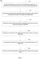
- Fig. 2 is a flow chart depicting an exemplary computer implemented process 200 of routing data through a dynamically selected edge node for data transmission between autonomous systems according to an embodiment of the present disclosure.
- Process 200 may be implemented by the edge nodes in Carrier A in Fig. 1 for example, where data is to be routed between a source node in a first autonomous system to a destination node in a second autonomous system.
- the first and second autonomous system may communicate with each other using BPG.
- the first autonomous system includes a control center and a plurality of edge nodes each pre-allocated to a subnetwork or a group of IP addresses of the first autonomous system.
- the IP address IP A1 is pre-allocated with the first edge node and the IP address IP A2 is pre-allocated with the second edge node.
- the pre-allocation can be informed to the external autonomous systems by way of broadcasting.
- a request is generated at the source node for visiting the destination node.
- the IP address of the source node is extracted from the request. Based on the IP address IP A1, the first edge node is identified. Data is routed between the source node and the destination node through the first edge node.
- a route detection request may be broadcast to a plurality of edge nodes that are eligible as egress nodes for the first autonomous system.
- each of the plurality of edge nodes detects performance data with respect to the candidate links between the edge node and the destination node.
- each edge nodes sends the detected performance data to the control center for performance evaluation according to predetermined evaluation criteria.
- the evaluation is triggered by a determination that the network performance of the first edge node with respect to the destination node has becomes satisfactory.
- the present disclosure is not limited to any specific event that triggers the evaluation.
- performance detection, evaluation and dynamic switching are limited to preselected destination nodes and/or source nodes, for example that have higher demands in quality of service.
- the present disclosure is not limited to such applications.
- an edge node is configured to generate test packets (e.g., in compliance with the Border Gateway Protocol (BGP)) and send them to the candidate routes directing to the destination node. Based on the route behaviors responsive to the test packets, the edge node derives performance information regarding the links between the edge node and the destination along the routes.
- the performance information may be related to quality of service policies regarding availability, throughput, bandwidth utilization, speed, stability, packet loss, round trip time (RTT), reliability, unreachable time, latency, error rates, CPU and/or memory utilization and associated latency, etc.
- an instruction generated from the control center is received at the second edge node to take over the data transmission from the first edge node.
- the second edge node modifies the packets by converting the source node's IP address from IP A1 to IP A2 (as illustrated in Fig. 1 ). The conversion may be performed in accordance with network address translation (NAT) as defined in the BGP or any other suitable manner that is well known in the art.
- NAT network address translation
- the returned data is delivered to the source node based on its original IP address, namely IP A1.
- IP A1 IP address
- Fig. 3 is a flow chart depicting an exemplary process of dynamically selecting an edge node for data transmission between autonomous systems according to an embodiment of the present disclosure.
- Process 300 may be implemented by a control center in Carrier A as shown in Fig. 1 for example, where data is routed between a source node in a first autonomous system to a destination node in a second autonomous system.
- the network performance data is collected from a plurality of edge nodes of the first autonomous system, the performance data related to a destination node in a second autonomous system
- the control center applies policy or other constraints to the network performance data to evaluate current route performance.
- the control center selects a second edge node and the associated link directing to the destination based on the evaluation.
- the control center generates a switching instruction to the first edge node and the second edge node for switching to using the second edge node.
- the present disclosure is not limited to any specific type or architecture of the network which includes the mechanism for discovering a route across different autonomous systems.
- the involved autonomous systems may be deployed on a wireless local area network (WLAN), a local area network (LAN), a wide area network (WAN), and etc.
- the autonomous systems according to the present disclosure may include a virtual network, a software-defined network (overlaying on physical network or natively as the primary network), a physical network only, or a combination thereof.
- the edge nodes may correspond to gateway nodes, virtual routers or any other suitable network elements.
- the edge nodes may correspond to SDN points-of-presence (POPs) or any other suitable network elements.
- POPs points-of-presence
- the edge nodes may correspond to proxy servers or any other suitable network element.
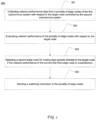
- Fig. 4 is a block diagram illustrating the configuration of an exemplary edge node device 400 in an autonomous system configured to route data across multiple autonomous systems according to an embodiment of the present disclosure.
- the edge node device 400 may be a gateway in a first autonomous system implemented on a general-purpose server computer with software and/or hardware logic configured to perform the functions as described in greater detail with reference to Figs. 1 and 2 .
- the edge node device 400 includes a main processor 401, system memory 402, a graphics processing unit (GPU) 403, I/O interfaces 404 and network circuits 405, an operating system 406 and application software 410.
- the application software 410 includes an edge node switching program 420 stored in the memory 402. When executed by the main processor 401, the edge node switching program 420 can communicate with a control center and the other edge nodes in first autonomous system and control the data flow from the first autonomous system to a second autonomous system.
- the edge node switching program 420 program includes a communication module 421, a detection module 422, and an NAT module 425.
- the communication module 421 is configured to receive instructions from the control center, generate and receive instructions from another edge node device with respect to selection and switching of edge node. It also serves to send the network performance data to the control center.
- the detection module 422 is configured to detect real-time performance data with respect to one or more selected target IP addresses. The detection may be performed on-demand or periodically in different embodiments.
- the detection module 422 includes BGP logic for collecting path information as defined in the BGP. For example, the BGP logic is used to detect the hop count of a path between the present edge node and a destination node.
- the detection module 422 can generate test packets (e.g., in compliance with the BGP) and send them to the candidate routes directing to a destination node. Based on the route behavior responsive to the test packets, the detection module 422 can derive performance information regarding the routes between the edge node and the destination node. In some embodiments, the performance information may be related to one or more attributes selected from availability, throughput, bandwidth utilization, speed, stability, packet loss, RTT, reliability, unreachable time, latency, error rates, CPU and memory utilization and associated latency. The present disclosure is not limited by the mechanism of detecting network performance. Nor is it limited by the performance information that can be detected by an edge node and used for edge node switching determinations.
- the NAT module 423 performs network address translation based on pre-allocation of a set of IP-addresses versus the plurality of edge nodes in the first autonomous system.
- the control center decides to switch from a first edge node to the present edge node 400
- the NAT module 423 modifies the data packets sent from the source node to translate its IP address from one that is pre-allocated to the first edge node to another that is pre-allocated to the second edge node, as described in greater detail above.
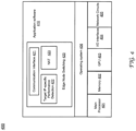
- Fig. 5 is a block diagram illustrating the configuration of an exemplary control center device 500 in a first autonomous system capable of dynamically selecting an optimal edge node for routing data across a second autonomous system based on real-time link performance data according to an embodiment of the present disclosure.
- the device 500 may be a general-purpose server computer.
- the control center 500 includes a main processor 501, system memory 502, a GPU 503, I/O interfaces 504 and network circuits 505, an operating system 506 and application software 510.
- the application software 510 includes a switching control center program 520 stored in the memory 502. When executed by the main processor 501, the switching control center program 520 can communicate with a plurality of edge nodes and coordinate them to control the data flow from a first autonomous system to a second autonomous system.
- the switching control center program 520 program includes a central routing database 521 of the first autonomous system, a detection request generation 522 module, an edge node selection module 523, a policy bank 524, and communication module 525.
- the central routing database 521 maintains the information regarding the arrangement and statuses of various components and the physical and logical structure of the first autonomous system as well as the dynamic link performance information provided from the plurality of edge nodes.
- the detection request generation module 522 generates a route detection request, e.g., each time a data packet is to be routed to a selected destination node.
- the edge node selection module 523 applies the set of policy constraints on the detected performance data according to a route optimization process to make an edge node selection decision. For example, the edge node selection module 523 can compare the evaluation results that are provided from the plurality of edge nodes to make the selection.
- the decision identifies a selected egress edge node and the selected link directing to the destination node in another autonomous system.
- the decision may also identify a link within the first autonomous system between an ingress node and the select egress edge node.
- the communication module 525 generates a switching instruction and sends it to the selected edge node.
- the switching control center program 520 may perform other various functions and processes as discussed in detail with reference to Figs. 1-3 .
- edge node switching program 400 and the switching control center program 500 may include a wide range of other modules and functions that are well known in the art. Techniques for implementing these programmed modules are well known in the art.
- control center program 420 can be implemented in any one or more suitable programming languages that are known to those skilled in the art, such as C, C++, Java, Python, Perl, C#, SQL, etc.
Landscapes
- Engineering & Computer Science (AREA)
- Computer Networks & Wireless Communication (AREA)
- Signal Processing (AREA)
- Data Exchanges In Wide-Area Networks (AREA)
- Environmental & Geological Engineering (AREA)
Applications Claiming Priority (4)
| Application Number | Priority Date | Filing Date | Title |
|---|---|---|---|
| CN201610423492.4A CN107517160B (zh) | 2016-06-15 | 2016-06-15 | 一种用于跨不同自治系统进行数据路由的方法、装置及系统 |
| US15/230,806 US10333809B2 (en) | 2016-06-15 | 2016-08-08 | Dynamic switching between edge nodes in autonomous network system |
| PCT/CN2017/084927 WO2017215400A1 (fr) | 2016-06-15 | 2017-05-18 | Commutation dynamique entre des noeuds périphériques dans un système de réseau autonome |
| EP17812511.8A EP3472983B1 (fr) | 2016-06-15 | 2017-05-18 | Commutation dynamique entre des noeuds périphériques dans un système de réseau autonome |
Related Parent Applications (1)
| Application Number | Title | Priority Date | Filing Date |
|---|---|---|---|
| EP17812511.8A Division EP3472983B1 (fr) | 2016-06-15 | 2017-05-18 | Commutation dynamique entre des noeuds périphériques dans un système de réseau autonome |
Publications (2)
| Publication Number | Publication Date |
|---|---|
| EP4415328A2 true EP4415328A2 (fr) | 2024-08-14 |
| EP4415328A3 EP4415328A3 (fr) | 2024-11-13 |
Family
ID=60660942
Family Applications (2)
| Application Number | Title | Priority Date | Filing Date |
|---|---|---|---|
| EP24185908.1A Pending EP4415328A3 (fr) | 2016-06-15 | 2017-05-18 | Commutation dynamique entre des noeuds périphériques dans un système de réseau autonome |
| EP17812511.8A Active EP3472983B1 (fr) | 2016-06-15 | 2017-05-18 | Commutation dynamique entre des noeuds périphériques dans un système de réseau autonome |
Family Applications After (1)
| Application Number | Title | Priority Date | Filing Date |
|---|---|---|---|
| EP17812511.8A Active EP3472983B1 (fr) | 2016-06-15 | 2017-05-18 | Commutation dynamique entre des noeuds périphériques dans un système de réseau autonome |
Country Status (4)
| Country | Link |
|---|---|
| US (2) | US10333809B2 (fr) |
| EP (2) | EP4415328A3 (fr) |
| CN (1) | CN107517160B (fr) |
| WO (1) | WO2017215400A1 (fr) |
Families Citing this family (15)
| Publication number | Priority date | Publication date | Assignee | Title |
|---|---|---|---|---|
| US10506037B2 (en) * | 2016-12-13 | 2019-12-10 | Alcatel Lucent | Discovery of ingress provider edge devices in egress peering networks |
| US10511507B2 (en) * | 2017-05-09 | 2019-12-17 | Cisco Technology, Inc. | Routing network traffic based on whether an application associated with traffic is a rerouting application as defined by a policy and whether a second path ranking exceeds a first path ranking |
| CN114095422A (zh) * | 2018-03-29 | 2022-02-25 | 华为技术有限公司 | 一种报文发送的方法、网络节点和系统 |
| CN108737544B (zh) * | 2018-05-22 | 2021-11-26 | 中国联合网络通信集团有限公司 | Cdn节点调度方法和装置 |
| CN110740287B (zh) * | 2018-07-20 | 2021-07-20 | 视联动力信息技术股份有限公司 | 一种自治网络的数据处理方法和装置 |
| US10798005B2 (en) * | 2018-09-13 | 2020-10-06 | International Business Machines Corporation | Optimizing application throughput |
| US10938946B2 (en) | 2019-01-14 | 2021-03-02 | Amdocs Development Limited | Handshake of application execution between edge nodes |
| CN110602180B (zh) * | 2019-08-26 | 2021-03-19 | 中国生态城市研究院有限公司 | 一种基于边缘计算的大数据用户行为分析方法及电子设备 |
| US11637710B2 (en) * | 2019-12-10 | 2023-04-25 | Jpmorgan Chase Bank, N.A. | Systems and methods for federated privacy management |
| CN113132228A (zh) * | 2019-12-31 | 2021-07-16 | 华为技术有限公司 | 一种路径校验方法及相关设备 |
| US11082336B1 (en) * | 2020-01-15 | 2021-08-03 | Cisco Technology, Inc. | Automatic configuration and connection of heterogeneous bandwidth managed multicast fabrics |
| CN113315645B (zh) * | 2020-02-27 | 2024-06-04 | 华为技术有限公司 | 配置性能探测指示信息的方法及相关设备 |
| CN111985181B (zh) * | 2020-08-25 | 2023-09-22 | 北京灵汐科技有限公司 | 一种节点布局方法、装置、计算机设备及存储介质 |
| CN114466008B (zh) * | 2021-12-22 | 2023-10-13 | 天翼云科技有限公司 | 一种云边通信系统、方法、装置、电子设备及存储介质 |
| US12395515B2 (en) * | 2023-03-06 | 2025-08-19 | International Business Machines Corporation | Dynamically placing tasks into edge nodes based on reputation scores |
Family Cites Families (39)
| Publication number | Priority date | Publication date | Assignee | Title |
|---|---|---|---|---|
| DE60223451T2 (de) * | 2001-06-14 | 2008-11-27 | Hitachi, Ltd. | System zur Quittierung von Datenpaketen |
| US7139278B2 (en) * | 2001-12-21 | 2006-11-21 | Nortel Networks Limited | Routing traffic in a communications network |
| US7529257B1 (en) * | 2003-04-30 | 2009-05-05 | Cisco Technology, Inc. | Method for supporting a GMPLS hierarchy through multiple routing instances |
| US7573826B1 (en) * | 2004-06-22 | 2009-08-11 | Nortel Networks Limited | Darwinian network |
| US7551551B2 (en) * | 2004-12-10 | 2009-06-23 | Cisco Technology, Inc. | Fast reroute (FRR) protection at the edge of a RFC 2547 network |
| US7535828B2 (en) * | 2005-03-18 | 2009-05-19 | Cisco Technology, Inc. | Algorithm for backup PE selection |
| US7697439B2 (en) * | 2005-05-10 | 2010-04-13 | Cisco Technology, Inc. | Method of determining transit costs across autonomous systems |
| JP4542045B2 (ja) * | 2006-01-24 | 2010-09-08 | アラクサラネットワークス株式会社 | データ通信装置およびその方法 |
| DE602006018533D1 (de) | 2006-03-31 | 2011-01-05 | Ericsson Telefon Ab L M | Zustandsaktualisierung in edge-routern |
| US20080002588A1 (en) * | 2006-06-30 | 2008-01-03 | Mccaughan Sherry L | Method and apparatus for routing data packets in a global IP network |
| US8081563B2 (en) * | 2006-10-11 | 2011-12-20 | Cisco Technology, Inc. | Protecting multi-segment pseudowires |
| US8355316B1 (en) * | 2009-12-16 | 2013-01-15 | Sprint Communications Company L.P. | End-to-end network monitoring |
| US8289845B1 (en) * | 2007-05-15 | 2012-10-16 | Avaya Inc. | Assured path optimization |
| WO2009054032A1 (fr) * | 2007-10-25 | 2009-04-30 | Fujitsu Limited | Dispositif de communication dans un réseau à commutation d'étiquettes |
| EP3419224B1 (fr) | 2008-01-23 | 2022-01-19 | Telefonaktiebolaget LM Ericsson (publ) | Sélection d'un noeud de bordure dans un réseau de communication à accès fixe |
| US8880724B2 (en) * | 2008-01-31 | 2014-11-04 | Cisco Technology, Inc. | Event triggered traceroute for optimized routing in a computer network |
| EP2329395A2 (fr) * | 2008-09-19 | 2011-06-08 | Limelight Networks, Inc. | Distribution de vignettes de serveur de flux de réseau de fourniture de contenus |
| US9762537B1 (en) * | 2008-10-14 | 2017-09-12 | Juniper Networks, Inc. | Secure path selection within computer networks |
| EP2209267B1 (fr) * | 2009-01-15 | 2017-05-03 | Teliasonera AB | Système et procédé pour acheminer le trafic de données |
| US8612622B2 (en) * | 2009-10-02 | 2013-12-17 | Limelight Networks, Inc. | Real-time message queuing for a processing ring |
| US8773978B2 (en) * | 2010-02-15 | 2014-07-08 | Futurewei Technologies, Inc. | System and method for protecting ingress and egress of a point-to-multipoint label switched path |
| RU2551814C2 (ru) * | 2010-06-29 | 2015-05-27 | Хуавей Текнолоджиз Ко., Лтд. | Инкапсуляция адреса асимметричной сети |
| US8588233B1 (en) * | 2010-12-31 | 2013-11-19 | Akamai Technologies, Inc. | Peer-to-peer connection establishment using TURN |
| US8908501B2 (en) * | 2011-07-15 | 2014-12-09 | Futurewei Technologies, Inc. | Procedures for finding a backup ingress of a point-to-multipoint label switched path |
| EP2754273A4 (fr) * | 2011-09-09 | 2015-03-11 | Ericsson Telefon Ab L M | Commutation de groupe de protection pour émulation de circuit |
| US9143429B2 (en) * | 2012-02-28 | 2015-09-22 | Google Inc. | Identifying an egress point to a network location |
| EP2829020A1 (fr) * | 2012-03-23 | 2015-01-28 | Telefonaktiebolaget L M Ericsson (Publ) | Sélection de pseudowire dans un réseau à redondance de pseudowires |
| US8831019B2 (en) * | 2012-05-18 | 2014-09-09 | Renesys | Path reconstruction and interconnection modeling (PRIM) |
| US8626910B1 (en) * | 2012-06-19 | 2014-01-07 | Edgecast Networks, Inc. | Systems and methods for performing localized server-side monitoring in a content delivery network |
| US9923897B2 (en) * | 2013-03-06 | 2018-03-20 | Surfeasy, Inc. | Edge server selection for enhanced services network |
| US9282026B2 (en) * | 2013-03-11 | 2016-03-08 | Dell Products L.P. | System and method for improved routing in autonomous systems |
| US9036463B2 (en) * | 2013-07-05 | 2015-05-19 | Cisco Technology, Inc. | Scalable BGP protection from edge node failure using dynamically assigned labels in data packets |
| US9444677B2 (en) * | 2013-10-18 | 2016-09-13 | Cisco Technology, Inc. | Scalable edge node protection using IPv6 segment routing extension header |
| US10079694B2 (en) * | 2014-08-29 | 2018-09-18 | Nokia Of America Corporation | Scalable virtual networks in SDN-based ethernet networks using VLANs |
| CN107005437B (zh) * | 2014-12-11 | 2020-01-17 | 瑞典爱立信有限公司 | 网络断层扫描的方法和装置 |
| US9800507B2 (en) * | 2015-02-10 | 2017-10-24 | Verizon Patent And Licensing Inc. | Application-based path computation |
| US11121967B2 (en) | 2015-03-05 | 2021-09-14 | Algoblu Holdings Limited | Data routing across multiple autonomous network systems |
| US9929941B2 (en) * | 2015-05-26 | 2018-03-27 | Cisco Technology, Inc. | Fast convergence for redundant edge devices |
| US11252199B2 (en) * | 2015-07-15 | 2022-02-15 | Oracle International Corporation | Redirecting packets in an autonomous system |
-
2016
- 2016-06-15 CN CN201610423492.4A patent/CN107517160B/zh active Active
- 2016-08-08 US US15/230,806 patent/US10333809B2/en active Active
-
2017
- 2017-05-18 EP EP24185908.1A patent/EP4415328A3/fr active Pending
- 2017-05-18 WO PCT/CN2017/084927 patent/WO2017215400A1/fr not_active Ceased
- 2017-05-18 EP EP17812511.8A patent/EP3472983B1/fr active Active
-
2019
- 2019-03-21 US US16/360,890 patent/US11108662B2/en active Active
Also Published As
| Publication number | Publication date |
|---|---|
| US10333809B2 (en) | 2019-06-25 |
| US20170366426A1 (en) | 2017-12-21 |
| CN107517160B (zh) | 2020-08-18 |
| WO2017215400A1 (fr) | 2017-12-21 |
| EP3472983A1 (fr) | 2019-04-24 |
| EP3472983B1 (fr) | 2024-07-03 |
| CN107517160A (zh) | 2017-12-26 |
| US11108662B2 (en) | 2021-08-31 |
| EP4415328A3 (fr) | 2024-11-13 |
| US20190238434A1 (en) | 2019-08-01 |
| EP3472983A4 (fr) | 2020-01-15 |
Similar Documents
| Publication | Publication Date | Title |
|---|---|---|
| US11108662B2 (en) | Dynamic switching between edge nodes in autonomous network system | |
| US11121967B2 (en) | Data routing across multiple autonomous network systems | |
| TWI803687B (zh) | 用於路由最佳化的系統及其方法 | |
| US9461923B2 (en) | Performance-based routing in software-defined network (SDN) | |
| EP3624408B1 (fr) | Procédé de génération d'entrée de table de transfert, dispositif de commande et dispositif de réseau | |
| US7751331B1 (en) | Technique for policy conflict resolution using priority with variance | |
| US7619982B2 (en) | Active probe path management | |
| JP2022532729A (ja) | スライスベースルーティング | |
| US12131185B2 (en) | Sharing and oversubscription of general-purpose graphical processing units in data centers | |
| US11294730B2 (en) | Process placement in a cloud environment based on automatically optimized placement policies and process execution profiles | |
| US20200371846A1 (en) | Adaptive application assignment to distributed cloud resources | |
| US20150100625A1 (en) | Data Transmission System | |
| HK1246528A1 (zh) | 一种用於跨不同自治系统进行数据路由的方法、装置及系统 | |
| Kushwaha et al. | IPv6 flow-label based application aware routing in SDNs | |
| US20250175514A1 (en) | Quality of experience directed network resource handling | |
| HK1246528B (zh) | 一种用於跨不同自治系统进行数据路由的方法、装置及系统 | |
| HK1229970A (en) | Data routing across multiple autonomous network systems | |
| HK1229970A1 (en) | Data routing across multiple autonomous network systems | |
| WO2025077998A1 (fr) | Explicabilité d'interfaces de gestion d'intention | |
| HK1229970B (zh) | 跨多个自治网络系统的数据路由 |
Legal Events
| Date | Code | Title | Description |
|---|---|---|---|
| PUAI | Public reference made under article 153(3) epc to a published international application that has entered the european phase |
Free format text: ORIGINAL CODE: 0009012 |
|
| STAA | Information on the status of an ep patent application or granted ep patent |
Free format text: STATUS: THE APPLICATION HAS BEEN PUBLISHED |
|
| AC | Divisional application: reference to earlier application |
Ref document number: 3472983 Country of ref document: EP Kind code of ref document: P |
|
| AK | Designated contracting states |
Kind code of ref document: A2 Designated state(s): AL AT BE BG CH CY CZ DE DK EE ES FI FR GB GR HR HU IE IS IT LI LT LU LV MC MK MT NL NO PL PT RO RS SE SI SK SM TR |
|
| REG | Reference to a national code |
Ref country code: DE Ref legal event code: R079 Free format text: PREVIOUS MAIN CLASS: H04L0045020000 Ipc: H04L0041120000 |
|
| PUAL | Search report despatched |
Free format text: ORIGINAL CODE: 0009013 |
|
| AK | Designated contracting states |
Kind code of ref document: A3 Designated state(s): AL AT BE BG CH CY CZ DE DK EE ES FI FR GB GR HR HU IE IS IT LI LT LU LV MC MK MT NL NO PL PT RO RS SE SI SK SM TR |
|
| RIC1 | Information provided on ipc code assigned before grant |
Ipc: H04L 43/10 20220101ALN20241008BHEP Ipc: H04L 45/02 20220101ALI20241008BHEP Ipc: H04L 45/42 20220101ALI20241008BHEP Ipc: H04L 41/12 20220101AFI20241008BHEP |
|
| STAA | Information on the status of an ep patent application or granted ep patent |
Free format text: STATUS: REQUEST FOR EXAMINATION WAS MADE |
|
| 17P | Request for examination filed |
Effective date: 20250512 |