EP4415249A1 - Marine propulsion device - Google Patents
Marine propulsion device Download PDFInfo
- Publication number
- EP4415249A1 EP4415249A1 EP24150064.4A EP24150064A EP4415249A1 EP 4415249 A1 EP4415249 A1 EP 4415249A1 EP 24150064 A EP24150064 A EP 24150064A EP 4415249 A1 EP4415249 A1 EP 4415249A1
- Authority
- EP
- European Patent Office
- Prior art keywords
- rotor
- detector
- calculated
- propulsion device
- detectors
- Prior art date
- Legal status (The legal status is an assumption and is not a legal conclusion. Google has not performed a legal analysis and makes no representation as to the accuracy of the status listed.)
- Granted
Links
Images

Classifications
-
- H—ELECTRICITY
- H02—GENERATION; CONVERSION OR DISTRIBUTION OF ELECTRIC POWER
- H02P—CONTROL OR REGULATION OF ELECTRIC MOTORS, ELECTRIC GENERATORS OR DYNAMO-ELECTRIC CONVERTERS; CONTROLLING TRANSFORMERS, REACTORS OR CHOKE COILS
- H02P6/00—Arrangements for controlling synchronous motors or other dynamo-electric motors using electronic commutation dependent on the rotor position; Electronic commutators therefor
- H02P6/14—Electronic commutators
- H02P6/15—Controlling commutation time
- H02P6/153—Controlling commutation time wherein the commutation is advanced from position signals phase in function of the speed
-
- B—PERFORMING OPERATIONS; TRANSPORTING
- B63—SHIPS OR OTHER WATERBORNE VESSELS; RELATED EQUIPMENT
- B63H—MARINE PROPULSION OR STEERING
- B63H1/00—Propulsive elements directly acting on water
- B63H1/02—Propulsive elements directly acting on water of rotary type
- B63H1/12—Propulsive elements directly acting on water of rotary type with rotation axis substantially in propulsive direction
- B63H1/14—Propellers
- B63H1/16—Propellers having a shrouding ring attached to blades
-
- B—PERFORMING OPERATIONS; TRANSPORTING
- B63—SHIPS OR OTHER WATERBORNE VESSELS; RELATED EQUIPMENT
- B63H—MARINE PROPULSION OR STEERING
- B63H23/00—Transmitting power from propulsion power plant to propulsive elements
- B63H23/22—Transmitting power from propulsion power plant to propulsive elements with non-mechanical gearing
- B63H23/24—Transmitting power from propulsion power plant to propulsive elements with non-mechanical gearing electric
-
- B—PERFORMING OPERATIONS; TRANSPORTING
- B63—SHIPS OR OTHER WATERBORNE VESSELS; RELATED EQUIPMENT
- B63H—MARINE PROPULSION OR STEERING
- B63H5/00—Arrangements on vessels of propulsion elements directly acting on water
- B63H5/07—Arrangements on vessels of propulsion elements directly acting on water of propellers
- B63H5/14—Arrangements on vessels of propulsion elements directly acting on water of propellers characterised by being mounted in non-rotating ducts or rings, e.g. adjustable for steering purpose
-
- H—ELECTRICITY
- H02—GENERATION; CONVERSION OR DISTRIBUTION OF ELECTRIC POWER
- H02P—CONTROL OR REGULATION OF ELECTRIC MOTORS, ELECTRIC GENERATORS OR DYNAMO-ELECTRIC CONVERTERS; CONTROLLING TRANSFORMERS, REACTORS OR CHOKE COILS
- H02P6/00—Arrangements for controlling synchronous motors or other dynamo-electric motors using electronic commutation dependent on the rotor position; Electronic commutators therefor
- H02P6/14—Electronic commutators
- H02P6/16—Circuit arrangements for detecting position
- H02P6/17—Circuit arrangements for detecting position and for generating speed information
-
- B—PERFORMING OPERATIONS; TRANSPORTING
- B63—SHIPS OR OTHER WATERBORNE VESSELS; RELATED EQUIPMENT
- B63H—MARINE PROPULSION OR STEERING
- B63H23/00—Transmitting power from propulsion power plant to propulsive elements
- B63H2023/005—Transmitting power from propulsion power plant to propulsive elements using a drive acting on the periphery of a rotating propulsive element, e.g. on a dented circumferential ring on a propeller, or a propeller acting as rotor of an electric motor
Definitions
- the present invention relates to a marine propulsion device.
- a marine propulsion device including a duct including a stator, and a propeller including a rim that includes a rotor facing the stator is known in general.
- Such a marine propulsion device is disclosed in JP 2022-018646 A , for example.
- JP 2022-018646 A discloses an outboard motor (marine propulsion device) including a duct including a stator, and a propeller including a rim that includes a rotor located radially inwardly of the stator so as to face the stator, and blades provided radially inwardly of the rim.
- a conventional outboard motor (marine propulsion device) as disclosed in JP 2022-018646 A includes a detector that detects a magnetic flux density generated by a magnet of a rotor. Furthermore, the conventional outboard motor includes a controller that calculates a magnet position of the rotor based on the magnetic flux density detected by the detector and performs a control to apply a current to a stator at the timing at which the rotor is able to obtain a maximum torque based on the calculated magnet position of the rotor. Moreover, the detector faces the rotor.
- a marine propulsion device having the features of independent claim 1. Preferred embodiments are laid down in the dependent claims.
- a marine propulsion device includes a duct including a stator, a propeller including a rim including a rotor provided radially inward of the stator and facing the stator, and blades provided radially inward of the rim, a detector facing the rotor via a metal member and configured to detect a magnetic flux density generated by a magnet of the rotor, and a controller configured or programmed to calculate a magnet position of the rotor based on the magnetic flux density detected by the detector, and perform a control to apply a current to the stator at a timing at which the rotor is able to obtain a maximum torque based on a calculated magnet position of the rotor.
- the controller is configured or programmed to calculate a rotation speed of the rotor based on the magnetic flux density detected by the detector, and correct a deviation in the calculated magnet position of the rotor due to an eddy current generated in the metal member based on a calculated rotation speed of the rotor.
- the controller is configured or programmed to calculate the rotation speed of the rotor based on the magnetic flux density detected by the detector, and correct the deviation in the calculated magnet position of the rotor due to the eddy current generated in the metal member based on the calculated rotation speed of the rotor. Accordingly, even when a deviation occurs in the calculated magnet position of the rotor due to the eddy current generated in the metal member, the deviation in the calculated magnet position of the rotor due to the eddy current generated in the metal member is corrected based on the rotation speed of the rotor.
- the rotation speed of the rotor is calculated based on a length of time for one cycle of the magnetic flux density corresponding to an electrical angle of 360 degrees, and thus the rotation speed of the rotor is accurately detected even when a deviation occurs in the calculated magnet position of the rotor. Therefore, a current is applied to the stator at the timing at which the rotor is able to obtain a maximum torque based on the calculated magnet position of the rotor with the deviation corrected. That is, the rotor obtains the maximum torque. Consequently, in a structure including the duct including the stator, and the propeller including the rim that includes the rotor facing the stator, an output of a motor including the stator and the rotor is improved.
- the detector is preferably adjacent to the stator in an axial direction of the rotor and preferably faces the rotor. Accordingly, even when the rotor faces the stator, the detector faces the rotor.
- the detector is preferably accommodated in a space inside a storage made of the metal member and located in an upper portion of the duct. Accordingly, the detector is located on the relatively upper side of the duct. Therefore, as compared with a case in which the detector is accommodated in a portion of the duct other than the storage located in the upper portion, the detector is located relatively close to the controller generally located above the duct. Consequently, complex routing of a signal line connecting the detector to the controller is reduced or prevented.
- a marine propulsion device preferably further includes a housing provided above the duct, the controller is preferably accommodated in a space inside the housing, and the space inside the storage in which the detector is accommodated is preferably connected to the space inside the housing in which the controller is accommodated. Accordingly, the space in which the detector is accommodated is connected to the space in which the controller is accommodated, and thus the signal line connecting the detector to the controller is easily routed.
- three-phase AC power is preferably supplied to the stator
- the detector preferably includes three detectors configured to detect three-phase magnetic flux densities generated by the magnet of the rotor, respectively
- the controller is preferably configured or programmed to calculate the rotation speed of the rotor based on one of the three-phase magnetic flux densities detected by the three detectors, respectively, and correct deviations in magnet positions of the rotor calculated based on the three-phase magnetic flux densities, respectively, based on a calculated rotation speed of the rotor. Accordingly, in a structure in which three-phase AC power is supplied, the rotor obtains the maximum torque.
- the three detectors are preferably aligned along an alignment direction perpendicular to an axial direction of the rotor in a horizontal plane, and a thickness of the metal member between the rotor and a detector located at a center in the alignment direction among the three detectors is preferably different from a thickness of the metal member between the rotor and a detector located on a first side in the alignment direction among the three detectors and a thickness of the metal member between the rotor and a detector located on a second side in the alignment direction among the three detectors.
- the width of a gap between a surface of the metal member on the rotor side and the outer peripheral surface of the rim including the rotor at a position corresponding to the detector located at the center in the assignment direction is smaller than the width of a gap between the surface of the metal member on the rotor side and the outer peripheral surface of the rim including the rotor at a position corresponding to the detector located on the first side in the alignment direction and the width of a gap between the surface of the metal member on the rotor side and the outer peripheral surface of the rim including the rotor at a position corresponding to the detector located on the second side in the alignment direction.
- a marine propulsion device preferably further includes a storage configured to store correction information indicating a relationship between the rotation speed of the rotor and a correction value to correct the deviation in the calculated magnet position of the rotor, and the controller is preferably configured or programmed to correct the deviation in the calculated magnet position of the rotor based on the calculated rotation speed of the rotor and the correction information. Accordingly, the deviation in the calculated magnet position of the rotor is easily corrected based on the calculated rotation speed of the rotor and the correction information stored in the storage.
- the storage is preferably configured to store the correction information for an entire range of the rotation speed of the rotor. Accordingly, the deviation in the calculated magnet position of the rotor is easily corrected over the entire range of the rotation speed of the rotor.
- the storage is preferably configured to store the correction information represented by a mathematical formula, a map, or a table. Accordingly, the correction information is easily stored in the storage using the mathematical formula, the map, or the table.
- the storage is preferably configured to store the correction information represented by the mathematical formula
- the controller is preferably configured or programmed to calculate the correction value based on the calculated rotation speed of the rotor and the correction information represented by the mathematical formula, and correct the deviation in the calculated magnet position of the rotor based on the calculated correction value. Accordingly, when the correction information is stored in the storage using the mathematical formula, the deviation in the calculated magnet position of the rotor is easily corrected based on the calculated rotation speed of the rotor and the correction information stored in the storage.
- a marine propulsion device 100 and a marine vessel 110 according to preferred embodiments are now described with reference to FIGS. 1 to 8 .
- the marine vessel 110 includes a hull 101, a bracket 102, and the marine propulsion device 100.
- the marine propulsion device 100 is attached to a stern 101a of the hull 101 via the bracket 102. That is, the marine propulsion device 100 is an outboard motor to propel the marine vessel 110.
- the marine vessel 110 may be a relatively small marine vessel used for sightseeing or fishing, for example.
- the marine propulsion device 100 includes a cowling 10, an upper case 20, a lower case 30, a duct 40, and a propeller 50.
- the cowling 10, the upper case 20, the lower case 30, the duct 40, and the propeller 50 are aligned in this order from the top (Z1 side) to the bottom (Z2 side) of the marine propulsion device 100. That is, the lower case 30 is located above the duct 40.
- the lower case 30 is an example of a "housing".
- the upward-downward direction of the marine propulsion device 100 is defined as a Z direction (first direction).
- the upper side and the lower side of the marine propulsion device 100 are defined as the Z1 side and the Z2 side, respectively.
- the axial direction, radial direction, and circumferential direction of a rotor 54 (see FIG. 3 ) described below are defined as an A direction, an R direction, and a C direction, respectively.
- a first side (hull 101 side) and a second side (a side opposite to the hull 101 side) in the axial direction (A direction) of the rotor 54 are defined as an A1 side and an A2 side, respectively.
- the radially inner side and the radially outer side of the rotor 54 are defined as an R1 side and an R2 side, respectively.
- the central axis 90 (see FIG. 2 ) of the propeller 50 extends along the A direction.
- the cowling 10 is attached to the stern 101a of the hull 101 via the bracket 102.
- the cowling 10 and the upper case 20 are fixed to each other.
- the lower case 30 and the duct 40 are fixed to each other.
- the lower case 30 and the duct 40 are rotatable in the right-left direction of the marine propulsion device 100 with respect to the cowling 10 and the upper case 20.
- the lower case 30 and the duct 40 are rotated with respect to the cowling 10 and the upper case 20 such that the orientation of the propeller 50 with respect to the hull 101 is changed.
- the duct 40 includes a cylindrical duct ring 41, a duct hub 42 provided on the R1 side of the duct ring 41 and extending along the A direction, and a plurality of fins 43 extending in the R direction to connect the duct hub 42 to the duct ring 41.
- the propeller 50 includes an annular rim 51, a propeller hub 52 provided on the R1 side of the rim 51 and extending along the A direction, and a plurality of blades 53 extending in the R direction to connect the propeller hub 52 to the rim 51. That is, the plurality of blades 53 are provided on the R1 side of the rim 51.
- the propeller hub 52 is supported by the duct hub 42 so as to be rotatable in the C direction with respect to the duct hub 42. That is, the propeller 50 including the propeller hub 52 is rotatable in the C direction with respect to the duct 40 including the duct hub 42. Rotation of the propeller 50 generates a thrust to propel the marine vessel 110.
- An annular recess 41a is provided on a surface of the duct ring 41 on the R1 side.
- the rim 51 of the propeller 50 is located in the annular recess 41a.
- the duct ring 41 includes a stator 44.
- the stator 44 includes an annular stator core (not shown) including a plurality of slots, and coils (not shown) in the plurality of slots of the stator core. Three-phase AC power is supplied to the coils of the stator 44.
- the rim 51 (propeller 50) includes the rotor 54.
- the rotor 54 includes an annular rotor core (not shown) and a magnet (not shown) embedded in the rotor core.
- the rotor 54 is located on the R1 side of the stator 44 so as to face the stator 44.
- a motor that rotates the propeller 50 includes the stator 44 and the rotor 54. That is, the marine propulsion device 100 is an electric outboard motor.
- a gap G is provided between the outer peripheral surface 51a of the rim 51 and the inner peripheral surface 40a of the duct 40 in the R direction.
- the gap G extends along the A direction.
- An end 54a of the rotor 54 on the A2 side and an end 44a of the stator 44 on the A2 side are deviated from each other in the A direction.
- the gap G extends along the C direction.
- each of the rotor 54 and the stator 44 is covered with a resin.
- the gap G is defined by the outer peripheral surface 51a of the rim 51 made of the resin covering the rotor 54 and the inner peripheral surface 40a of the duct 40 made of the resin covering the stator 44.
- the marine propulsion device 100 includes detectors 60, a controller 70, and a storage 80.
- Each of the detectors 60 includes a magnetic sensor.
- the detectors 60 detect magnetic flux densities MD generated by the magnet of the rotor 54.
- the detectors 60 output detection signals DS to the controller 70 based on the timing (detection points in FIG. 7 ) at which the magnetic flux densities MD exceed a predetermined threshold TH (see FIG. 7 ).
- the detectors 60 are adjacent to the stator 44 on the A2 side of the stator 44 in the A direction and face the rotor 54.
- three detectors 60 are provided to detect three-phase magnetic flux densities MD (see FIG. 7 ) generated by the magnet of the rotor 54, respectively.
- the three detectors 60 are aligned along an alignment direction (W direction) perpendicular to the A direction in a horizontal plane.
- the W direction is along the right-left direction of the marine propulsion device 100.
- the controller 70 includes a processor such as a central processing unit (CPU).
- the controller 70 calculates magnet position MP of the rotor 54 based on the detection signals DS input from the detectors 60. That is, the controller 70 calculates the magnet position MP of the rotor 54 based on the magnetic flux densities MD detected by the detectors 60. Then, the controller 70 performs a control to apply three-phase alternating currents to the coils of the stator 44 at the timing at which the rotor 54 is able to obtain a maximum torque based on the calculated magnet position MP of the rotor 54. As shown in FIG. 1 , the controller 70 is accommodated in a space S2 inside the lower case 30.
- CPU central processing unit
- the storage 80 includes a nonvolatile memory.
- the storage 80 stores programs etc. used for control by the controller 70.
- the detectors 60 face the rotor 54 via a metal (aluminum, for example) member MM. Specifically, the detectors 60 are accommodated in a space S1 inside a storage 45 made of the metal member MM and located in an upper portion of the duct 40. As shown in FIG. 1 , the space S1 inside the storage 45 in which the detectors 60 are accommodated is connected to the space S2 inside the lower case 30 in which the controller 70 is accommodated.
- FIG. 7 a change over time of the magnetic flux when one of the detectors 60 faces the rotor 54 via the metal member MM, and a change over time of the magnetic flux when the detector 60 faces the rotor 54 via air are shown by solid and dotted lines, respectively.
- the controller 70 calculates the rotation speed TN of the rotor 54 based on the magnetic flux densities MD detected by the detectors 60. Then, the controller 70 corrects a deviation in the calculated magnet position MP of the rotor 54 due to the eddy currents generated in the metal member MM, based on the calculated rotation speed TN of the rotor 54.
- the controller 70 calculates the rotation speed TN of the rotor 54 based on a length of time for one cycle of the magnetic flux densities MD detected by the detectors 60, which corresponds to an electrical angle of 360 degrees (see FIG. 7 ).
- the storage 80 stores correction information Cl indicating the relationship between the rotation speed TN of the rotor 54 and a correction value CV (see FIG. 8 ) to correct the deviation in the calculated magnet position MP of the rotor 54.
- the controller 70 corrects the deviation in the calculated magnet position MP of the rotor 54 due to the eddy currents generated in the metal member MM (see FIG. 4 ), based on the calculated rotation speed TN of the rotor 54 and the correction information Cl stored in the storage 80.
- the storage 80 stores the correction information CI for the entire range of the rotation speed TN of the rotor 54.
- the storage 80 stores the correction information Cl represented by a mathematical formula.
- the rotation speed TN of the rotor 54 and the correction value CV are represented by a linear function.
- the controller 70 calculates the correction value CV (see FIG. 8 ) based on the calculated rotation speed TN of the rotor 54 and the correction information Cl represented by the mathematical formula. Then, the controller 70 corrects the deviation in the calculated magnet position MP of the rotor 54 based on the calculated correction value CV.
- the thickness t1 of the metal member MM between the rotor 54 and a detector 61 located at the center in the W direction among the three detectors 60 is different from the thickness t2 of the metal member MM between the rotor 54 and a detector 62 located on the W1 side (a first side in the W direction) among the three detectors 60 and the thickness t3 of the metal member MM between the rotor 54 and a detector 63 located on the W2 side (a second side in the W direction) among the three detectors 60. Therefore, a deviation in the magnet position MP (see FIG. 6 ) of the rotor 54 calculated based on a magnetic flux density MD (see FIG.
- the controller 70 calculates the rotation speed TN of the rotor 54 based on one of the three-phase magnetic flux densities MD (see FIG. 7 ) detected by the three detectors 60 (see FIG. 5 ). Then, the controller 70 corrects the deviations in the magnet positions MP of the rotor 54 calculated based on the three-phase magnetic flux densities MD, respectively, based on the calculated rotation speed TN of the rotor 54.
- the thickness t2 (see FIG. 5 ) is substantially the same as the thickness t3 (see FIG. 5 ), and thus the correction value CV for the deviation in the magnet position MP of the rotor 54 calculated based on the magnetic flux density MD detected by the detector 62 (see FIG.
- the correction information Cl to correct the deviation in the magnet position MP of the rotor 54 calculated based on the magnetic flux density MD detected by the detector 61 is shown by a solid line
- the correction information Cl to correct the deviation in the magnet position MP of the rotor 54 calculated based on the magnetic flux density MD detected by the detector 62 and the correction information Cl to correct the deviation in the magnet position MP of the rotor 54 calculated based on the magnetic flux density MD detected by the detector 63 are shown by a dotted line.
- a control flow by the controller 70 of the marine propulsion device 100 is now described with reference to FIG. 9 .
- step S101 the controller 70 calculates the magnet position MP of the rotor 54 based on the magnetic flux densities MD detected by the detectors 60. Specifically, the detectors 60 output the detection signals DS to the controller 70 based on the timing at which the magnetic flux densities MD exceed the predetermined threshold TH. Then, the controller 70 calculates the magnet position MP of the rotor 54 based on the detection signals DS input from the detectors 60.
- step S102 the controller 70 calculates the rotation speed TN of the rotor 54 based on the magnetic flux densities MD detected by the detectors 60. Specifically, the controller 70 calculates the rotation speed TN of the rotor 54 based on a length of time for one cycle of the magnetic flux densities MD detected by the detectors 60, which corresponds to an electrical angle of 360 degrees.
- the process operation in step S102 may be performed before step S101.
- step S103 the controller 70 corrects the deviation in the calculated magnet position MP of the rotor 54 due to the eddy currents generated in the metal member MM, based on the calculated rotation speed TN of the rotor 54.
- the storage 80 stores the correction information Cl indicating the relationship between the rotation speed TN of the rotor 54 and the correction value CV to correct the deviation in the calculated magnet position MP of the rotor 54.
- the controller 70 corrects the deviation in the calculated magnet position MP of the rotor 54 due to the eddy currents generated in the metal member MM based on the calculated rotation speed TN of the rotor 54 and the correction information Cl stored in the storage 80.
- step S104 the controller 70 performs a control to apply three-phase alternating currents to the coils of the stator 44 at the timing at which the rotor 54 is able to obtain a maximum torque, based on the calculated magnet position MP of the rotor 54 with the deviation corrected.
- step S101 to step S104 are repeated until the controller 70 finishes a control to apply three-phase alternating currents to the coils of the stator 44.
- the controller 70 is configured or programmed to calculate the rotation speed TN of the rotor 54 based on the magnetic flux densities MD detected by the detectors 60, and correct the deviation in the calculated magnet position MP of the rotor 54 due to the eddy currents generated in the metal member MM based on the calculated rotation speed TN of the rotor 54. Accordingly, even when a deviation occurs in the calculated magnet position MP of the rotor 54 due to the eddy currents generated in the metal member MM, the deviation in the calculated magnet position of the rotor 54 due to the eddy currents generated in the metal member MM is corrected based on the rotation speed TN of the rotor 54.
- the rotation speed TN of the rotor 54 is calculated based on a length of time for one cycle of the magnetic flux densities MD corresponding to an electrical angle of 360 degrees, and thus the rotation speed TN of the rotor 54 is accurately detected even when a deviation occurs in the calculated magnet position of the rotor. Therefore, currents are applied to the stator 44 at the timing at which the rotor 54 is able to obtain a maximum torque based on the calculated magnet position MP of the rotor 54 with the deviation corrected. That is, the rotor 54 obtains the maximum torque. Consequently, in a structure including the duct 40 including the stator 44, and the propeller 50 including the rim 51 that includes the rotor 54 facing the stator 44, an output of the motor including the stator 44 and the rotor 54 is improved.
- the detectors 60 are adjacent to the stator 44 in the A direction (the axial direction of the rotor 54) and face the rotor 54. Accordingly, even when the rotor 54 faces the stator 44, the detectors 60 face the rotor 54.
- the detectors 60 are accommodated in the space S1 inside the storage 45 made of the metal member MM and located in the upper portion of the duct 40. Accordingly, the detectors 60 are located on the relatively upper side of the duct 40. Therefore, as compared with a case in which the detectors 60 are accommodated in a portion of the duct 40 other than the storage 45 located in the upper portion, the detectors 60 are located relatively close to the controller 70 generally located above the duct 40. Consequently, complex routing of signal lines connecting the detectors 60 to the controller 70 is reduced or prevented.
- the marine propulsion device 100 includes the lower case 30 (housing) above the duct 40.
- the controller 70 is accommodated in the space S2 inside the lower case 30.
- the space S1 inside the storage 45 in which the detectors 60 are accommodated is connected to the space S2 inside the lower case 30 in which the controller 70 is accommodated. Accordingly, the space S1 in which the detectors 60 are accommodated is connected to the space S2 in which the controller 70 is accommodated, and thus the signal lines connecting the detectors 60 to the controller 70 are easily routed.
- three-phase AC power is supplied to the stator 44.
- the three detectors 60 are provided to detect the three-phase magnetic flux densities MD generated by the magnet of the rotor 54, respectively.
- the controller 70 is configured or programmed to calculate the rotation speed TN of the rotor 54 based on one of the three-phase magnetic flux densities MD detected by the three detectors 60, respectively, and correct the deviations in the magnet positions MP of the rotor 54 calculated based on the three-phase magnetic flux densities MD, respectively, based on the calculated rotation speed TN of the rotor 54. Accordingly, in a structure in which three-phase AC power is supplied, the rotor 54 obtains the maximum torque.
- the three detectors 60 are aligned along the W direction (alignment direction) perpendicular to the A direction (the axial direction of the rotor 54) in the horizontal plane.
- the thickness t1 of the metal member MM between the rotor 54 and the detector 61 located at the center in the W direction among the three detectors 60 is different from the thickness t2 of the metal member MM between the rotor 54 and the detector 62 located on the W1 side (the first side in the W direction) among the three detectors 60 and the thickness t3 of the metal member MM between the rotor 54 and the detector 63 located on the W2 side (the second side in the W direction) among the three detectors 60.
- the width of the gap G between a surface of the metal member MM on the rotor 54 side and the outer peripheral surface 51a of the rim 51 including the rotor 54 at a position corresponding to the detector 61 located at the center in the W direction is smaller than the width of the gap G between the surface of the metal member MM on the rotor 54 side and the outer peripheral surface 51a of the rim 51 including the rotor 54 at a position corresponding to the detector 62 located on the W1 side in the W direction and the width of the gap G between the surface of the metal member MM on the rotor 54 side and the outer peripheral surface 51a of the rim 51 including the rotor 54 at a position corresponding to the detector 63 located on the W2 side in the W direction.
- the marine propulsion device 100 includes the storage 80 to store the correction information Cl indicating the relationship between the rotation speed TN of the rotor 54 and the correction value CV to correct the deviation in the calculated magnet position MP of the rotor 54.
- the controller 70 is configured or programmed to correct the deviation in the calculated magnet position MP of the rotor 54 based on the calculated rotation speed TN of the rotor 54 and the correction information Cl. Accordingly, the deviation in the calculated magnet position MP of the rotor 54 is easily corrected based on the calculated rotation speed TN of the rotor 54 and the correction information Cl stored in the storage 80.
- the storage 80 is operable to store the correction information CI for the entire range of the rotation speed TN of the rotor 54. Accordingly, the deviation in the calculated magnet position MP of the rotor 54 is easily corrected over the entire range of the rotation speed TN of the rotor 54.
- the storage 80 is operable to store the correction information Cl represented by the mathematical formula. Accordingly, the correction information is easily stored in the storage 80 using the mathematical formula.
- the controller 70 is configured or programmed to calculate the correction value CV based on the calculated rotation speed TN of the rotor 54 and the correction information Cl represented by the mathematical formula, and correct the deviation in the calculated magnet position MP of the rotor 54 based on the calculated correction value CV. Accordingly, when the correction information Cl is stored in the storage 80 using the mathematical formula, the deviation in the calculated magnet position MP of the rotor 54 is easily corrected based on the calculated rotation speed TN of the rotor 54 and the correction information Cl stored in the storage 80.
- the storage 80 preferably stores the correction information Cl represented by the mathematical formula in preferred embodiments described above, the present teaching is not restricted to this.
- the storage may alternatively store correction information represented by a map or a table, for example.
- the storage 80 preferably stores the correction information CI for the entire range of the rotation speed TN of the rotor 54 in preferred embodiments described above, the present teaching is not restricted to this. In the present teaching, the storage may alternatively store correction information only for a partial range of the rotation speed of the rotor.
- the present teaching is not restricted to this.
- three detectors may alternatively be aligned along the circumferential direction of the rotor, and the thickness of the metal member between the rotor and a detector located at the center in the circumferential direction of the rotor among the three detectors may alternatively be equal to or substantially equal to the thickness of the metal member between the rotor and a detector located on a first side in the circumferential direction of the rotor among the three detectors and the thickness of the metal member between the rotor and a detector located on a second side in the circumferential direction of the rotor among the three detectors.
- the thickness t2 of the metal member MM between the rotor 54 and the detector 62 located on the W1 side (the first side in the W direction (the alignment direction perpendicular to the axial direction of the rotor 54 in the horizontal plane)) among the three detectors 60 is preferably substantially the same as the thickness t3 of the metal member MM between the rotor 54 and the detector 63 located on the W2 side (the second side in the W direction) among the three detectors 60 in preferred embodiments described above, the present teaching is not restricted to this.
- the thickness of the metal member between the rotor and the detector located on the first side in the alignment direction among the three detectors may alternatively be different from the thickness of the metal member between the rotor and the detector located on the second side in the alignment direction among the three detectors.
- two-phase AC power may alternatively be supplied to the stator
- two detectors may alternatively be provided to detect two-phase magnetic flux densities generated by the magnet of the rotor, respectively
- the controller may alternatively calculate the rotation speed of the rotor based on one of the two-phase magnetic flux densities detected by the two detectors, respectively, and correct deviations in magnet positions of the rotor calculated based on the two-phase magnetic flux densities, respectively, based on the calculated rotation speed of the rotor.
- single-phase AC power may be supplied to the stator, only one detector may alternatively be provided to detect a single-phase magnetic flux density generated by the magnet of the rotor, and the controller may calculate the rotation speed of the rotor based on the single-phase magnetic flux density detected by one detector, and correct a deviation in a magnet position of the rotor calculated based on the single-phase magnetic flux density, based on the calculated rotation speed of the rotor.
- the present teaching is not restricted to this.
- the space inside the storage in which the detectors are accommodated may not be connected to the space inside the housing in which the controller is accommodated.
- the present teaching is not restricted to this.
- the detectors may alternatively be accommodated in a portion other than the storage made of the metal member and located in the upper portion of the duct.
- the present teaching is not restricted to this.
- the detectors may alternatively face the rotor without being adjacent to the stator in the axial direction of the rotor.
- the marine propulsion device 100 is preferably an outboard motor attached to the hull 101 in preferred embodiments described above, the present teaching is not restricted to this.
- the marine propulsion device may alternatively be an inboard motor provided inside the hull, or an inboard-outboard motor attached to the hull such that a portion of the inboard-outboard motor is provided inside the hull.
Landscapes
- Engineering & Computer Science (AREA)
- Chemical & Material Sciences (AREA)
- Combustion & Propulsion (AREA)
- Mechanical Engineering (AREA)
- Ocean & Marine Engineering (AREA)
- Power Engineering (AREA)
- Permanent Field Magnets Of Synchronous Machinery (AREA)
Abstract
Description
- The present invention relates to a marine propulsion device.
- A marine propulsion device including a duct including a stator, and a propeller including a rim that includes a rotor facing the stator is known in general. Such a marine propulsion device is disclosed in
JP 2022-018646 A -
JP 2022-018646 A - Although not disclosed in
JP 2022-018646 A JP 2022-018646 A - In the conventional outboard motor (marine propulsion device) as disclosed in
JP 2022-018646 A JP 2022-018646 A - It is an object of the present invention to provide a marine propulsion device including a duct including a stator, and a propeller including a rim that includes a rotor facing the stator and in which an output of a motor including the stator and the rotor is improved. According to the present invention, said object is solved by a marine propulsion device having the features of
independent claim 1. Preferred embodiments are laid down in the dependent claims. - A marine propulsion device according to a preferred embodiment includes a duct including a stator, a propeller including a rim including a rotor provided radially inward of the stator and facing the stator, and blades provided radially inward of the rim, a detector facing the rotor via a metal member and configured to detect a magnetic flux density generated by a magnet of the rotor, and a controller configured or programmed to calculate a magnet position of the rotor based on the magnetic flux density detected by the detector, and perform a control to apply a current to the stator at a timing at which the rotor is able to obtain a maximum torque based on a calculated magnet position of the rotor. The controller is configured or programmed to calculate a rotation speed of the rotor based on the magnetic flux density detected by the detector, and correct a deviation in the calculated magnet position of the rotor due to an eddy current generated in the metal member based on a calculated rotation speed of the rotor.
- In a marine propulsion device according to a preferred embodiment, the controller is configured or programmed to calculate the rotation speed of the rotor based on the magnetic flux density detected by the detector, and correct the deviation in the calculated magnet position of the rotor due to the eddy current generated in the metal member based on the calculated rotation speed of the rotor. Accordingly, even when a deviation occurs in the calculated magnet position of the rotor due to the eddy current generated in the metal member, the deviation in the calculated magnet position of the rotor due to the eddy current generated in the metal member is corrected based on the rotation speed of the rotor. The rotation speed of the rotor is calculated based on a length of time for one cycle of the magnetic flux density corresponding to an electrical angle of 360 degrees, and thus the rotation speed of the rotor is accurately detected even when a deviation occurs in the calculated magnet position of the rotor. Therefore, a current is applied to the stator at the timing at which the rotor is able to obtain a maximum torque based on the calculated magnet position of the rotor with the deviation corrected. That is, the rotor obtains the maximum torque. Consequently, in a structure including the duct including the stator, and the propeller including the rim that includes the rotor facing the stator, an output of a motor including the stator and the rotor is improved.
- In a marine propulsion device according to a preferred embodiment, the detector is preferably adjacent to the stator in an axial direction of the rotor and preferably faces the rotor. Accordingly, even when the rotor faces the stator, the detector faces the rotor.
- In a marine propulsion device according to a preferred embodiment, the detector is preferably accommodated in a space inside a storage made of the metal member and located in an upper portion of the duct. Accordingly, the detector is located on the relatively upper side of the duct. Therefore, as compared with a case in which the detector is accommodated in a portion of the duct other than the storage located in the upper portion, the detector is located relatively close to the controller generally located above the duct. Consequently, complex routing of a signal line connecting the detector to the controller is reduced or prevented.
- In such a case, a marine propulsion device preferably further includes a housing provided above the duct, the controller is preferably accommodated in a space inside the housing, and the space inside the storage in which the detector is accommodated is preferably connected to the space inside the housing in which the controller is accommodated. Accordingly, the space in which the detector is accommodated is connected to the space in which the controller is accommodated, and thus the signal line connecting the detector to the controller is easily routed.
- In a marine propulsion device according to a preferred embodiment, three-phase AC power is preferably supplied to the stator, the detector preferably includes three detectors configured to detect three-phase magnetic flux densities generated by the magnet of the rotor, respectively, and the controller is preferably configured or programmed to calculate the rotation speed of the rotor based on one of the three-phase magnetic flux densities detected by the three detectors, respectively, and correct deviations in magnet positions of the rotor calculated based on the three-phase magnetic flux densities, respectively, based on a calculated rotation speed of the rotor. Accordingly, in a structure in which three-phase AC power is supplied, the rotor obtains the maximum torque.
- In such a case, the three detectors are preferably aligned along an alignment direction perpendicular to an axial direction of the rotor in a horizontal plane, and a thickness of the metal member between the rotor and a detector located at a center in the alignment direction among the three detectors is preferably different from a thickness of the metal member between the rotor and a detector located on a first side in the alignment direction among the three detectors and a thickness of the metal member between the rotor and a detector located on a second side in the alignment direction among the three detectors. Accordingly, the width of a gap between a surface of the metal member on the rotor side and the outer peripheral surface of the rim including the rotor at a position corresponding to the detector located at the center in the assignment direction is smaller than the width of a gap between the surface of the metal member on the rotor side and the outer peripheral surface of the rim including the rotor at a position corresponding to the detector located on the first side in the alignment direction and the width of a gap between the surface of the metal member on the rotor side and the outer peripheral surface of the rim including the rotor at a position corresponding to the detector located on the second side in the alignment direction. Consequently, even when the three detectors are aligned along the alignment direction perpendicular to the axial direction of the rotor in the horizontal plane, an excessively uneven width of the gap between the inner peripheral surface of the duct and the outer peripheral surface of the rim is reduced or prevented.
- A marine propulsion device according to a preferred embodiment preferably further includes a storage configured to store correction information indicating a relationship between the rotation speed of the rotor and a correction value to correct the deviation in the calculated magnet position of the rotor, and the controller is preferably configured or programmed to correct the deviation in the calculated magnet position of the rotor based on the calculated rotation speed of the rotor and the correction information. Accordingly, the deviation in the calculated magnet position of the rotor is easily corrected based on the calculated rotation speed of the rotor and the correction information stored in the storage.
- In such a case, the storage is preferably configured to store the correction information for an entire range of the rotation speed of the rotor. Accordingly, the deviation in the calculated magnet position of the rotor is easily corrected over the entire range of the rotation speed of the rotor.
- In a marine propulsion device further including the storage to store the correction information, the storage is preferably configured to store the correction information represented by a mathematical formula, a map, or a table. Accordingly, the correction information is easily stored in the storage using the mathematical formula, the map, or the table.
- In such a case, the storage is preferably configured to store the correction information represented by the mathematical formula, and the controller is preferably configured or programmed to calculate the correction value based on the calculated rotation speed of the rotor and the correction information represented by the mathematical formula, and correct the deviation in the calculated magnet position of the rotor based on the calculated correction value. Accordingly, when the correction information is stored in the storage using the mathematical formula, the deviation in the calculated magnet position of the rotor is easily corrected based on the calculated rotation speed of the rotor and the correction information stored in the storage.
- The above and other elements, features, steps, characteristics and advantages of preferred embodiments will become more apparent from the following detailed description of the preferred embodiments with reference to the attached drawings.
-
-
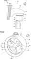
FIG. 1 is a side view of a marine propulsion device according to a preferred embodiment. -
FIG. 2 is a perspective view of a duct and a rim of a marine propulsion device according to a preferred embodiment. -
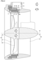
FIG. 3 is a sectional view illustrating the structure of a duct and a rim of a marine propulsion device according to a preferred embodiment. -
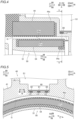
FIG. 4 is an enlarged view of a portion IV inFIG. 3 . -
FIG. 5 is sectional view taken along the line V-V inFIG. 4 . -
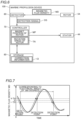
FIG. 6 is a block diagram of a control system of a marine propulsion device according to a preferred embodiment. -
FIG. 7 is a diagram illustrating a deviation in a calculated magnet position of a rotor caused by eddy currents generated in a metal member in a marine propulsion device according to a preferred embodiment. -
FIG. 8 is a diagram illustrating correction information stored in a storage of a marine propulsion device according to a preferred embodiment. -
FIG. 9 is a diagram showing a control flow by a controller of a marine propulsion device according to a preferred embodiment. - Preferred embodiments are hereinafter described with reference to the drawings.
- A
marine propulsion device 100 and amarine vessel 110 according to preferred embodiments are now described with reference toFIGS. 1 to 8 . - As shown in
FIG. 1 , themarine vessel 110 includes ahull 101, abracket 102, and themarine propulsion device 100. Themarine propulsion device 100 is attached to astern 101a of thehull 101 via thebracket 102. That is, themarine propulsion device 100 is an outboard motor to propel themarine vessel 110. Themarine vessel 110 may be a relatively small marine vessel used for sightseeing or fishing, for example. - The
marine propulsion device 100 includes a cowling 10, anupper case 20, alower case 30, aduct 40, and apropeller 50. Thecowling 10, theupper case 20, thelower case 30, theduct 40, and thepropeller 50 are aligned in this order from the top (Z1 side) to the bottom (Z2 side) of themarine propulsion device 100. That is, thelower case 30 is located above theduct 40. Thelower case 30 is an example of a "housing". - In the following description, the upward-downward direction of the
marine propulsion device 100 is defined as a Z direction (first direction). The upper side and the lower side of themarine propulsion device 100 are defined as the Z1 side and the Z2 side, respectively. Furthermore, the axial direction, radial direction, and circumferential direction of a rotor 54 (seeFIG. 3 ) described below are defined as an A direction, an R direction, and a C direction, respectively. A first side (hull 101 side) and a second side (a side opposite to thehull 101 side) in the axial direction (A direction) of therotor 54 are defined as an A1 side and an A2 side, respectively. The radially inner side and the radially outer side of therotor 54 are defined as an R1 side and an R2 side, respectively. The central axis 90 (seeFIG. 2 ) of thepropeller 50 extends along the A direction. - The
cowling 10 is attached to the stern 101a of thehull 101 via thebracket 102. Thecowling 10 and theupper case 20 are fixed to each other. Thelower case 30 and theduct 40 are fixed to each other. Thelower case 30 and theduct 40 are rotatable in the right-left direction of themarine propulsion device 100 with respect to thecowling 10 and theupper case 20. Thelower case 30 and theduct 40 are rotated with respect to thecowling 10 and theupper case 20 such that the orientation of thepropeller 50 with respect to thehull 101 is changed. - As shown in
FIG. 2 , theduct 40 includes acylindrical duct ring 41, aduct hub 42 provided on the R1 side of theduct ring 41 and extending along the A direction, and a plurality offins 43 extending in the R direction to connect theduct hub 42 to theduct ring 41. - The
propeller 50 includes anannular rim 51, apropeller hub 52 provided on the R1 side of therim 51 and extending along the A direction, and a plurality ofblades 53 extending in the R direction to connect thepropeller hub 52 to therim 51. That is, the plurality ofblades 53 are provided on the R1 side of therim 51. - The
propeller hub 52 is supported by theduct hub 42 so as to be rotatable in the C direction with respect to theduct hub 42. That is, thepropeller 50 including thepropeller hub 52 is rotatable in the C direction with respect to theduct 40 including theduct hub 42. Rotation of thepropeller 50 generates a thrust to propel themarine vessel 110. - An
annular recess 41a is provided on a surface of theduct ring 41 on the R1 side. Therim 51 of thepropeller 50 is located in theannular recess 41a. - As shown in
FIG. 3 , the duct ring 41 (duct 40) includes astator 44. Thestator 44 includes an annular stator core (not shown) including a plurality of slots, and coils (not shown) in the plurality of slots of the stator core. Three-phase AC power is supplied to the coils of thestator 44. The rim 51 (propeller 50) includes therotor 54. Therotor 54 includes an annular rotor core (not shown) and a magnet (not shown) embedded in the rotor core. Therotor 54 is located on the R1 side of thestator 44 so as to face thestator 44. A motor that rotates thepropeller 50 includes thestator 44 and therotor 54. That is, themarine propulsion device 100 is an electric outboard motor. - As shown in
FIG. 4 , a gap G is provided between the outerperipheral surface 51a of therim 51 and the innerperipheral surface 40a of theduct 40 in the R direction. The gap G extends along the A direction. Anend 54a of therotor 54 on the A2 side and anend 44a of thestator 44 on the A2 side are deviated from each other in the A direction. As shown inFIG. 5 , the gap G extends along the C direction. - As shown in
FIG. 4 , each of therotor 54 and thestator 44 is covered with a resin. Thus, the gap G is defined by the outerperipheral surface 51a of therim 51 made of the resin covering therotor 54 and the innerperipheral surface 40a of theduct 40 made of the resin covering thestator 44. - As shown in
FIG. 6 , themarine propulsion device 100 includesdetectors 60, acontroller 70, and astorage 80. - Each of the
detectors 60 includes a magnetic sensor. Thedetectors 60 detect magnetic flux densities MD generated by the magnet of therotor 54. Thedetectors 60 output detection signals DS to thecontroller 70 based on the timing (detection points inFIG. 7 ) at which the magnetic flux densities MD exceed a predetermined threshold TH (seeFIG. 7 ). As shown inFIG. 4 , thedetectors 60 are adjacent to thestator 44 on the A2 side of thestator 44 in the A direction and face therotor 54. - As shown in
FIG. 5 , threedetectors 60 are provided to detect three-phase magnetic flux densities MD (seeFIG. 7 ) generated by the magnet of therotor 54, respectively. The threedetectors 60 are aligned along an alignment direction (W direction) perpendicular to the A direction in a horizontal plane. The W direction is along the right-left direction of themarine propulsion device 100. - As shown in
FIG. 6 , thecontroller 70 includes a processor such as a central processing unit (CPU). Thecontroller 70 calculates magnet position MP of therotor 54 based on the detection signals DS input from thedetectors 60. That is, thecontroller 70 calculates the magnet position MP of therotor 54 based on the magnetic flux densities MD detected by thedetectors 60. Then, thecontroller 70 performs a control to apply three-phase alternating currents to the coils of thestator 44 at the timing at which therotor 54 is able to obtain a maximum torque based on the calculated magnet position MP of therotor 54. As shown inFIG. 1 , thecontroller 70 is accommodated in a space S2 inside thelower case 30. - As shown in
FIG. 6 , thestorage 80 includes a nonvolatile memory. Thestorage 80 stores programs etc. used for control by thecontroller 70. - As shown in
FIG. 4 , thedetectors 60 face therotor 54 via a metal (aluminum, for example) member MM. Specifically, thedetectors 60 are accommodated in a space S1 inside astorage 45 made of the metal member MM and located in an upper portion of theduct 40. As shown inFIG. 1 , the space S1 inside thestorage 45 in which thedetectors 60 are accommodated is connected to the space S2 inside thelower case 30 in which thecontroller 70 is accommodated. - Therefore, as shown in
FIG. 7 , the phases of the magnetic flux densities MD detected by the detectors 60 (seeFIG. 6 ) are shifted due to eddy currents generated in the metal member MM. Accordingly, the magnet position MP (seeFIG. 6 ) of the rotor 54 (seeFIG. 4 ) calculated by the controller 70 (seeFIG. 6 ) based on the detection signals DS (seeFIG. 6 ) input from thedetectors 60 is deviated. InFIG. 7 , a change over time of the magnetic flux when one of thedetectors 60 faces therotor 54 via the metal member MM, and a change over time of the magnetic flux when thedetector 60 faces therotor 54 via air are shown by solid and dotted lines, respectively. - As shown in
FIG. 6 , thecontroller 70 calculates the rotation speed TN of therotor 54 based on the magnetic flux densities MD detected by thedetectors 60. Then, thecontroller 70 corrects a deviation in the calculated magnet position MP of therotor 54 due to the eddy currents generated in the metal member MM, based on the calculated rotation speed TN of therotor 54. - Specifically, the
controller 70 calculates the rotation speed TN of therotor 54 based on a length of time for one cycle of the magnetic flux densities MD detected by thedetectors 60, which corresponds to an electrical angle of 360 degrees (seeFIG. 7 ). Thestorage 80 stores correction information Cl indicating the relationship between the rotation speed TN of therotor 54 and a correction value CV (seeFIG. 8 ) to correct the deviation in the calculated magnet position MP of therotor 54. Then, thecontroller 70 corrects the deviation in the calculated magnet position MP of therotor 54 due to the eddy currents generated in the metal member MM (seeFIG. 4 ), based on the calculated rotation speed TN of therotor 54 and the correction information Cl stored in thestorage 80. - As shown in
FIG. 8 , the storage 80 (seeFIG. 6 ) stores the correction information CI for the entire range of the rotation speed TN of therotor 54. Thestorage 80 stores the correction information Cl represented by a mathematical formula. In the correction information Cl, the rotation speed TN of therotor 54 and the correction value CV are represented by a linear function. - As shown in
FIG. 6 , thecontroller 70 calculates the correction value CV (seeFIG. 8 ) based on the calculated rotation speed TN of therotor 54 and the correction information Cl represented by the mathematical formula. Then, thecontroller 70 corrects the deviation in the calculated magnet position MP of therotor 54 based on the calculated correction value CV. - As shown in
FIG. 5 , the thickness t1 of the metal member MM between therotor 54 and adetector 61 located at the center in the W direction among the threedetectors 60 is different from the thickness t2 of the metal member MM between therotor 54 and adetector 62 located on the W1 side (a first side in the W direction) among the threedetectors 60 and the thickness t3 of the metal member MM between therotor 54 and adetector 63 located on the W2 side (a second side in the W direction) among the threedetectors 60. Therefore, a deviation in the magnet position MP (seeFIG. 6 ) of therotor 54 calculated based on a magnetic flux density MD (seeFIG. 6 ) detected by thedetector 61 is different from a deviation in the magnet position MP of therotor 54 calculated based on a magnetic flux density MD detected by thedetector 62 and a deviation in the magnet position MP of therotor 54 calculated based on a magnetic flux density MD detected by thedetector 63. - Therefore, as shown in
FIG. 8 , the controller 70 (seeFIG. 6 ) calculates the rotation speed TN of therotor 54 based on one of the three-phase magnetic flux densities MD (seeFIG. 7 ) detected by the three detectors 60 (seeFIG. 5 ). Then, thecontroller 70 corrects the deviations in the magnet positions MP of therotor 54 calculated based on the three-phase magnetic flux densities MD, respectively, based on the calculated rotation speed TN of therotor 54. The thickness t2 (seeFIG. 5 ) is substantially the same as the thickness t3 (seeFIG. 5 ), and thus the correction value CV for the deviation in the magnet position MP of therotor 54 calculated based on the magnetic flux density MD detected by the detector 62 (seeFIG. 5 ) is substantially the same as the correction value CV for the deviation in the magnet position MP of therotor 54 calculated based on the magnetic flux density MD detected by the detector 63 (seeFIG. 5 ). InFIG. 8 , the correction information Cl to correct the deviation in the magnet position MP of therotor 54 calculated based on the magnetic flux density MD detected by thedetector 61 is shown by a solid line, and the correction information Cl to correct the deviation in the magnet position MP of therotor 54 calculated based on the magnetic flux density MD detected by thedetector 62 and the correction information Cl to correct the deviation in the magnet position MP of therotor 54 calculated based on the magnetic flux density MD detected by thedetector 63 are shown by a dotted line. - A control flow by the
controller 70 of themarine propulsion device 100 is now described with reference toFIG. 9 . - As shown in
FIG. 9 , in step S101, thecontroller 70 calculates the magnet position MP of therotor 54 based on the magnetic flux densities MD detected by thedetectors 60. Specifically, thedetectors 60 output the detection signals DS to thecontroller 70 based on the timing at which the magnetic flux densities MD exceed the predetermined threshold TH. Then, thecontroller 70 calculates the magnet position MP of therotor 54 based on the detection signals DS input from thedetectors 60. - Then, in step S102, the
controller 70 calculates the rotation speed TN of therotor 54 based on the magnetic flux densities MD detected by thedetectors 60. Specifically, thecontroller 70 calculates the rotation speed TN of therotor 54 based on a length of time for one cycle of the magnetic flux densities MD detected by thedetectors 60, which corresponds to an electrical angle of 360 degrees. The process operation in step S102 may be performed before step S101. - Then, in step S103, the
controller 70 corrects the deviation in the calculated magnet position MP of therotor 54 due to the eddy currents generated in the metal member MM, based on the calculated rotation speed TN of therotor 54. Specifically, thestorage 80 stores the correction information Cl indicating the relationship between the rotation speed TN of therotor 54 and the correction value CV to correct the deviation in the calculated magnet position MP of therotor 54. Then, thecontroller 70 corrects the deviation in the calculated magnet position MP of therotor 54 due to the eddy currents generated in the metal member MM based on the calculated rotation speed TN of therotor 54 and the correction information Cl stored in thestorage 80. - Then, in step S104, the
controller 70 performs a control to apply three-phase alternating currents to the coils of thestator 44 at the timing at which therotor 54 is able to obtain a maximum torque, based on the calculated magnet position MP of therotor 54 with the deviation corrected. - The process operations in step S101 to step S104 are repeated until the
controller 70 finishes a control to apply three-phase alternating currents to the coils of thestator 44. - According to the various preferred embodiments described above, the following advantageous effects are achieved.
- According to a preferred embodiment, the
controller 70 is configured or programmed to calculate the rotation speed TN of therotor 54 based on the magnetic flux densities MD detected by thedetectors 60, and correct the deviation in the calculated magnet position MP of therotor 54 due to the eddy currents generated in the metal member MM based on the calculated rotation speed TN of therotor 54. Accordingly, even when a deviation occurs in the calculated magnet position MP of therotor 54 due to the eddy currents generated in the metal member MM, the deviation in the calculated magnet position of therotor 54 due to the eddy currents generated in the metal member MM is corrected based on the rotation speed TN of therotor 54. The rotation speed TN of therotor 54 is calculated based on a length of time for one cycle of the magnetic flux densities MD corresponding to an electrical angle of 360 degrees, and thus the rotation speed TN of therotor 54 is accurately detected even when a deviation occurs in the calculated magnet position of the rotor. Therefore, currents are applied to thestator 44 at the timing at which therotor 54 is able to obtain a maximum torque based on the calculated magnet position MP of therotor 54 with the deviation corrected. That is, therotor 54 obtains the maximum torque. Consequently, in a structure including theduct 40 including thestator 44, and thepropeller 50 including therim 51 that includes therotor 54 facing thestator 44, an output of the motor including thestator 44 and therotor 54 is improved. - According to a preferred embodiment, the
detectors 60 are adjacent to thestator 44 in the A direction (the axial direction of the rotor 54) and face therotor 54. Accordingly, even when therotor 54 faces thestator 44, thedetectors 60 face therotor 54. - According to a preferred embodiment, the
detectors 60 are accommodated in the space S1 inside thestorage 45 made of the metal member MM and located in the upper portion of theduct 40. Accordingly, thedetectors 60 are located on the relatively upper side of theduct 40. Therefore, as compared with a case in which thedetectors 60 are accommodated in a portion of theduct 40 other than thestorage 45 located in the upper portion, thedetectors 60 are located relatively close to thecontroller 70 generally located above theduct 40. Consequently, complex routing of signal lines connecting thedetectors 60 to thecontroller 70 is reduced or prevented. - According to a preferred embodiment, the
marine propulsion device 100 includes the lower case 30 (housing) above theduct 40. Thecontroller 70 is accommodated in the space S2 inside thelower case 30. The space S1 inside thestorage 45 in which thedetectors 60 are accommodated is connected to the space S2 inside thelower case 30 in which thecontroller 70 is accommodated. Accordingly, the space S1 in which thedetectors 60 are accommodated is connected to the space S2 in which thecontroller 70 is accommodated, and thus the signal lines connecting thedetectors 60 to thecontroller 70 are easily routed. - According to a preferred embodiment, three-phase AC power is supplied to the
stator 44. The threedetectors 60 are provided to detect the three-phase magnetic flux densities MD generated by the magnet of therotor 54, respectively. Thecontroller 70 is configured or programmed to calculate the rotation speed TN of therotor 54 based on one of the three-phase magnetic flux densities MD detected by the threedetectors 60, respectively, and correct the deviations in the magnet positions MP of therotor 54 calculated based on the three-phase magnetic flux densities MD, respectively, based on the calculated rotation speed TN of therotor 54. Accordingly, in a structure in which three-phase AC power is supplied, therotor 54 obtains the maximum torque. - According to a preferred embodiment, the three
detectors 60 are aligned along the W direction (alignment direction) perpendicular to the A direction (the axial direction of the rotor 54) in the horizontal plane. The thickness t1 of the metal member MM between therotor 54 and thedetector 61 located at the center in the W direction among the threedetectors 60 is different from the thickness t2 of the metal member MM between therotor 54 and thedetector 62 located on the W1 side (the first side in the W direction) among the threedetectors 60 and the thickness t3 of the metal member MM between therotor 54 and thedetector 63 located on the W2 side (the second side in the W direction) among the threedetectors 60. Accordingly, the width of the gap G between a surface of the metal member MM on therotor 54 side and the outerperipheral surface 51a of therim 51 including therotor 54 at a position corresponding to thedetector 61 located at the center in the W direction is smaller than the width of the gap G between the surface of the metal member MM on therotor 54 side and the outerperipheral surface 51a of therim 51 including therotor 54 at a position corresponding to thedetector 62 located on the W1 side in the W direction and the width of the gap G between the surface of the metal member MM on therotor 54 side and the outerperipheral surface 51a of therim 51 including therotor 54 at a position corresponding to thedetector 63 located on the W2 side in the W direction. Consequently, even when the threedetectors 60 are aligned along the W direction perpendicular to the A direction in the horizontal plane, an excessively uneven width of the gap G between the innerperipheral surface 40a of theduct 40 and the outerperipheral surface 51a of therim 51 is reduced or prevented. - According to a preferred embodiment, the
marine propulsion device 100 includes thestorage 80 to store the correction information Cl indicating the relationship between the rotation speed TN of therotor 54 and the correction value CV to correct the deviation in the calculated magnet position MP of therotor 54. Thecontroller 70 is configured or programmed to correct the deviation in the calculated magnet position MP of therotor 54 based on the calculated rotation speed TN of therotor 54 and the correction information Cl. Accordingly, the deviation in the calculated magnet position MP of therotor 54 is easily corrected based on the calculated rotation speed TN of therotor 54 and the correction information Cl stored in thestorage 80. - According to a preferred embodiment, the
storage 80 is operable to store the correction information CI for the entire range of the rotation speed TN of therotor 54. Accordingly, the deviation in the calculated magnet position MP of therotor 54 is easily corrected over the entire range of the rotation speed TN of therotor 54. - According to a preferred embodiment, the
storage 80 is operable to store the correction information Cl represented by the mathematical formula. Accordingly, the correction information is easily stored in thestorage 80 using the mathematical formula. - According to a preferred embodiment, the
controller 70 is configured or programmed to calculate the correction value CV based on the calculated rotation speed TN of therotor 54 and the correction information Cl represented by the mathematical formula, and correct the deviation in the calculated magnet position MP of therotor 54 based on the calculated correction value CV. Accordingly, when the correction information Cl is stored in thestorage 80 using the mathematical formula, the deviation in the calculated magnet position MP of therotor 54 is easily corrected based on the calculated rotation speed TN of therotor 54 and the correction information Cl stored in thestorage 80. - The preferred embodiments described above are illustrative for present teaching but the present teaching also relates to modifications of the preferred embodiments.
- For example, while the
storage 80 preferably stores the correction information Cl represented by the mathematical formula in preferred embodiments described above, the present teaching is not restricted to this. In the present teaching, the storage may alternatively store correction information represented by a map or a table, for example. - While the
storage 80 preferably stores the correction information CI for the entire range of the rotation speed TN of therotor 54 in preferred embodiments described above, the present teaching is not restricted to this. In the present teaching, the storage may alternatively store correction information only for a partial range of the rotation speed of the rotor. - While the three
detectors 60 are preferably aligned along the W direction (alignment direction) perpendicular to the A direction (the axial direction of the rotor 54) in the horizontal plane, and the thickness t1 of the metal member MM between therotor 54 and thedetector 61 located at the center in the W direction among the threedetectors 60 is preferably different from the thickness t2 of the metal member MM between therotor 54 and thedetector 62 located on the W1 side (the first side in the W direction) among the threedetectors 60 and the thickness t3 of the metal member MM between therotor 54 and thedetector 63 located on the W2 side (the second side in the W direction) among the threedetectors 60 in preferred embodiments described above, the present teaching is not restricted to this. In the present teaching, three detectors may alternatively be aligned along the circumferential direction of the rotor, and the thickness of the metal member between the rotor and a detector located at the center in the circumferential direction of the rotor among the three detectors may alternatively be equal to or substantially equal to the thickness of the metal member between the rotor and a detector located on a first side in the circumferential direction of the rotor among the three detectors and the thickness of the metal member between the rotor and a detector located on a second side in the circumferential direction of the rotor among the three detectors. - While the thickness t2 of the metal member MM between the
rotor 54 and thedetector 62 located on the W1 side (the first side in the W direction (the alignment direction perpendicular to the axial direction of therotor 54 in the horizontal plane)) among the threedetectors 60 is preferably substantially the same as the thickness t3 of the metal member MM between therotor 54 and thedetector 63 located on the W2 side (the second side in the W direction) among the threedetectors 60 in preferred embodiments described above, the present teaching is not restricted to this. In the present teaching, the thickness of the metal member between the rotor and the detector located on the first side in the alignment direction among the three detectors may alternatively be different from the thickness of the metal member between the rotor and the detector located on the second side in the alignment direction among the three detectors. - While three-phase AC power is preferably supplied to the
stator 44, three detectors are preferably provided to detect the three-phase magnetic flux densities MD generated by the magnet of therotor 54, respectively, and thecontroller 70 preferably calculates the rotation speed TN of therotor 54 based on one of the three-phase magnetic flux densities MD detected by the threedetectors 60, respectively, and performs a control to correct the deviations in the magnet positions MP of therotor 54 calculated based on the three-phase magnetic flux densities MD, respectively, based on the calculated rotation speed TN of therotor 54 in preferred embodiments described above, the present teaching is not restricted to this. In the present teaching, two-phase AC power may alternatively be supplied to the stator, two detectors may alternatively be provided to detect two-phase magnetic flux densities generated by the magnet of the rotor, respectively, and the controller may alternatively calculate the rotation speed of the rotor based on one of the two-phase magnetic flux densities detected by the two detectors, respectively, and correct deviations in magnet positions of the rotor calculated based on the two-phase magnetic flux densities, respectively, based on the calculated rotation speed of the rotor. Alternatively, single-phase AC power may be supplied to the stator, only one detector may alternatively be provided to detect a single-phase magnetic flux density generated by the magnet of the rotor, and the controller may calculate the rotation speed of the rotor based on the single-phase magnetic flux density detected by one detector, and correct a deviation in a magnet position of the rotor calculated based on the single-phase magnetic flux density, based on the calculated rotation speed of the rotor. - While the space S1 inside the
storage 45 in which thedetectors 60 are accommodated is preferably connected to the space S2 inside the lower case 30 (housing) in which thecontroller 70 is accommodated in preferred embodiments described above, the present teaching is not restricted to this. In the present teaching, the space inside the storage in which the detectors are accommodated may not be connected to the space inside the housing in which the controller is accommodated. - While the
detectors 60 are preferably accommodated in the space S1 inside thestorage 45 made of the metal member MM and located in the upper portion of theduct 40 in preferred embodiments described above, the present teaching is not restricted to this. In the present teaching, the detectors may alternatively be accommodated in a portion other than the storage made of the metal member and located in the upper portion of the duct. - While the
detectors 60 are preferably adjacent to thestator 44 in the A direction (the axial direction of the rotor 54) and preferably face therotor 54 in preferred embodiments described above, the present teaching is not restricted to this. In the present teaching, the detectors may alternatively face the rotor without being adjacent to the stator in the axial direction of the rotor. - While the
marine propulsion device 100 is preferably an outboard motor attached to thehull 101 in preferred embodiments described above, the present teaching is not restricted to this. In the present teaching, the marine propulsion device may alternatively be an inboard motor provided inside the hull, or an inboard-outboard motor attached to the hull such that a portion of the inboard-outboard motor is provided inside the hull.
Claims (11)
- A marine propulsion device (100) comprising:a duct (40) including a stator (44);a propeller (50) including a rim (51) including a rotor (54) being rotatable around a central axis (90) of the propeller (50), the rotor (54) having an axial direction (A) that extends parallel to the central axis (90) of the propeller (50), the rotor (54) being provided radially inward of the stator (44), the rotor (54) facing the stator (44), and blades (53) provided radially inward of the rim (51);a detector (60) facing the rotor (54) in a first direction (Z) via a metal member (MM) and configured to detect a magnetic flux density (MD) generated by a magnet of the rotor (54); anda controller (70) configured or programmed to calculate a magnet position (MP) of the rotor (54) based on the magnetic flux density (MD) detected by the detector (60), and perform a control to apply a current to the stator (44) at a timing at which the rotor (54) is able to obtain a maximum torque based on a calculated magnet position (MP) of the rotor (54); whereinthe controller (70) is configured or programmed to calculate a rotation speed (TN) of the rotor (54) based on the magnetic flux density (MD) detected by the detector (60), and correct a deviation in the calculated magnet position (MP) of the rotor (54) due to an eddy current generated in the metal member (MM) based on a calculated rotation speed (TN) of the rotor (54).
- The marine propulsion device (100) according to claim 1, wherein the detector (60) is adjacent to the stator (44) in the axial direction (A) of the rotor (54) and faces the rotor (54).
- The marine propulsion device (100) according to claim 1 or 2, wherein the detector (60) is accommodated in a space (S1) inside a storage (45) made of the metal member (MM) and located in an upper portion of the duct (40).
- The marine propulsion device (100) according to claim 3, further comprising:a housing (30) provided above the duct (40); whereinthe controller (70) is accommodated in a space (S2) inside the housing (30); andthe space (S1) inside the storage (45) in which the detector (60) is accommodated is connected to the space (S2) inside the housing (30) in which the controller (70) is accommodated.
- The marine propulsion device (100) according to at least one of the claims 1 to 4, wherein three-phase AC power is supplied to the stator (44);the detector (60) includes three detectors (60, 61, 62, 63) configured to detect three-phase magnetic flux densities (MD) generated by the magnet of the rotor (54), respectively; andthe controller (70) is configured or programmed to calculate the rotation speed (TN) of the rotor (54) based on one of the three-phase magnetic flux densities (MD) detected by the three detectors (60, 61, 62, 63), respectively, and correct deviations in magnet positions (MP) of the rotor (54) calculated based on the three-phase magnetic flux densities (MD), respectively, based on a calculated rotation speed (TN) of the rotor (54).
- The marine propulsion device (100) according to claim 5, wherein the three detectors (60, 61, 62, 63) are aligned along an alignment direction (W) perpendicular to the first direction (Z) and the axial direction (A) of the rotor (54); and
a thickness (t1) of the metal member (MM) between the rotor (54) and a detector (61) located at a center in the alignment direction (W) among the three detectors (60, 61, 62, 63) is different from a thickness (t2) of the metal member (MM) between the rotor (54) and a detector (62) located on a first side in the alignment direction (W) among the three detectors (60, 61, 62, 63) and a thickness (t3) of the metal member (MM) between the rotor (54) and a detector (63) located on a second side in the alignment direction (W) among the three detectors (60, 61, 62, 63). - The marine propulsion device (100) according to at least one of the claims 1 to 6, further comprising:a storage (80) configured to store correction information (CI) indicating a relationship between the rotation speed (TN) of the rotor (54) and a correction value (CV) to correct the deviation in the calculated magnet position (MP) of the rotor (54); whereinthe controller (70) is configured or programmed to correct the deviation in the calculated magnet position (MP) of the rotor (54) based on the calculated rotation speed (TN) of the rotor (54) and the correction information (CI).
- The marine propulsion device (100) according to claim 7, wherein the storage (80) is configured to store the correction information (CI) for an entire range of the rotation speed (TN) of the rotor (54).
- The marine propulsion device (100) according to claim 7, wherein the storage (80) is configured to store the correction information (CI) represented by a mathematical formula, a map, or a table.
- The marine propulsion device (100) according to claim 9, wherein the storage (80) is configured to store the correction information (CI) represented by the mathematical formula; and
the controller (70) is configured or programmed to calculate the correction value (CV) based on the calculated rotation speed (TN) of the rotor (54) and the correction information (CI) represented by the mathematical formula, and correct the deviation in the calculated magnet position (MP) of the rotor (54) based on the calculated correction value (CV). - A marine vessel (110) including a hull (101) with a marine propulsion device (100) according to at least one of the claims 1 to 10 attached to a stern (101a) of the hull (101), wherein the first direction (Z) in which the detector (60) is facing the rotor (54) is an upward-downward direction of the marine vessel (110).
Applications Claiming Priority (1)
| Application Number | Priority Date | Filing Date | Title |
|---|---|---|---|
| JP2023017120A JP2024112203A (en) | 2023-02-07 | 2023-02-07 | Marine propulsion unit and vessel |
Publications (2)
| Publication Number | Publication Date |
|---|---|
| EP4415249A1 true EP4415249A1 (en) | 2024-08-14 |
| EP4415249B1 EP4415249B1 (en) | 2025-09-10 |
Family
ID=89430476
Family Applications (1)
| Application Number | Title | Priority Date | Filing Date |
|---|---|---|---|
| EP24150064.4A Active EP4415249B1 (en) | 2023-02-07 | 2024-01-02 | Marine propulsion device |
Country Status (3)
| Country | Link |
|---|---|
| US (1) | US12668341B2 (en) |
| EP (1) | EP4415249B1 (en) |
| JP (1) | JP2024112203A (en) |
Families Citing this family (2)
| Publication number | Priority date | Publication date | Assignee | Title |
|---|---|---|---|---|
| JP2024082913A (en) * | 2022-12-09 | 2024-06-20 | ヤマハ発動機株式会社 | Marine propulsion unit and vessel |
| JP2026122511A (en) * | 2025-01-16 | 2026-07-29 | ヤマハ発動機株式会社 | Ship propulsion systems and ships |
Citations (3)
| Publication number | Priority date | Publication date | Assignee | Title |
|---|---|---|---|---|
| EP2591993A1 (en) * | 2011-11-08 | 2013-05-15 | Yamaha Hatsudoki Kabushiki Kaisha | Marine vessel propulsion device |
| US9074866B2 (en) * | 2011-06-30 | 2015-07-07 | Hitachi Automotive Systems, Ltd. | Rotational angle measurement apparatus, control apparatus, and rotation-machine system |
| JP2022018646A (en) | 2020-07-16 | 2022-01-27 | ヤマハ発動機株式会社 | Outboard motor |
Family Cites Families (15)
| Publication number | Priority date | Publication date | Assignee | Title |
|---|---|---|---|---|
| CN101939623B (en) * | 2008-02-07 | 2013-10-09 | 日立金属株式会社 | Rotation angle detection device, rotating machine and rotation angle detection method |
| JP5551408B2 (en) * | 2009-10-22 | 2014-07-16 | 株式会社東海理化電機製作所 | Rotation angle detector |
| JP2012080652A (en) * | 2010-09-30 | 2012-04-19 | Aisin Aw Co Ltd | Controller of driving device |
| JP2013132200A (en) | 2011-11-24 | 2013-07-04 | Panasonic Corp | Motor controller |
| JP2013207980A (en) * | 2012-03-29 | 2013-10-07 | Panasonic Corp | Motor driving system and motor driving method |
| CN204721259U (en) | 2012-09-10 | 2015-10-21 | 三菱电机株式会社 | Drive circuits, electric motors, pump motors, air conditioners, ventilation fans and water heaters |
| JP6135248B2 (en) * | 2013-03-29 | 2017-05-31 | 株式会社富士通ゼネラル | Advance angle simulation method and advance angle simulation program |
| JP6206093B2 (en) | 2013-10-30 | 2017-10-04 | サンケン電気株式会社 | Motor drive device and motor device |
| JP2018079743A (en) * | 2016-11-14 | 2018-05-24 | ヤマハ発動機株式会社 | Ship propulsion unit and ship with the same |
| JP7205104B2 (en) * | 2018-08-08 | 2023-01-17 | 株式会社デンソー | Control device and vehicle drive system |
| GB201813335D0 (en) * | 2018-08-15 | 2018-09-26 | Technelec Ltd | Flux linkage to current observer for synchronous machines |
| US10763772B1 (en) * | 2019-04-25 | 2020-09-01 | GM Global Technology Operations LLC | Excitation of cycloidal electric machine |
| JP6861867B1 (en) * | 2020-02-26 | 2021-04-21 | 三菱電機株式会社 | Angle detection device and control device for rotary electric machine |
| JP6991297B1 (en) * | 2020-10-21 | 2022-01-12 | 三菱電機株式会社 | Current detector and AC rotary machine control device |
| CN115411978B (en) * | 2022-08-12 | 2025-05-13 | 浙江吉利控股集团有限公司 | Motor position signal fault judgment method, device, system and vehicle |
-
2023
- 2023-02-07 JP JP2023017120A patent/JP2024112203A/en active Pending
-
2024
- 2024-01-02 EP EP24150064.4A patent/EP4415249B1/en active Active
- 2024-02-01 US US18/429,511 patent/US12668341B2/en active Active
Patent Citations (3)
| Publication number | Priority date | Publication date | Assignee | Title |
|---|---|---|---|---|
| US9074866B2 (en) * | 2011-06-30 | 2015-07-07 | Hitachi Automotive Systems, Ltd. | Rotational angle measurement apparatus, control apparatus, and rotation-machine system |
| EP2591993A1 (en) * | 2011-11-08 | 2013-05-15 | Yamaha Hatsudoki Kabushiki Kaisha | Marine vessel propulsion device |
| JP2022018646A (en) | 2020-07-16 | 2022-01-27 | ヤマハ発動機株式会社 | Outboard motor |
Also Published As
| Publication number | Publication date |
|---|---|
| JP2024112203A (en) | 2024-08-20 |
| US12668341B2 (en) | 2026-06-30 |
| US20240262475A1 (en) | 2024-08-08 |
| EP4415249B1 (en) | 2025-09-10 |
Similar Documents
| Publication | Publication Date | Title |
|---|---|---|
| EP4415249B1 (en) | Marine propulsion device | |
| US20200031446A1 (en) | Rotating electrical machine apparatus | |
| US20100201213A1 (en) | Motor | |
| US20170363444A1 (en) | Rotation angle detection apparatus | |
| US9929686B2 (en) | Controller for permanent magnet synchronous motor, image forming apparatus, and control method | |
| JP2008082996A (en) | Resolver, motor, and power steering device | |
| JP2007101480A (en) | Resolver | |
| US20050046296A1 (en) | Electric motor and steering system using the same | |
| US7427858B2 (en) | Resolver reference position adjustment method | |
| US10432067B2 (en) | Electric motor | |
| US20050273295A1 (en) | Angle detection apparatus and torque detection apparatus | |
| US7944168B2 (en) | Device for controlling a rotating electrical machine | |
| JP4816919B2 (en) | Control device for brushless motor | |
| US11063503B2 (en) | Brushless motor | |
| CN107040096A (en) | Motor and its decomposer | |
| JP2011217584A (en) | Motor drive unit and method of controlling the same | |
| JPWO2022224381A5 (en) | ||
| EP4382409A1 (en) | Marine propulsion device | |
| JP6841189B2 (en) | Brushless motor | |
| JP2001190099A (en) | Vector control method of permanent magnet synchronous motor | |
| KR910003919Y1 (en) | Brushless motor | |
| US10931215B2 (en) | Motor control apparatus and motor control method | |
| US10985678B2 (en) | Motor control apparatus and motor control method | |
| JPS61280753A (en) | Variable speed permanent magnet motor | |
| JPH07318368A (en) | Rotation angle detector |
Legal Events
| Date | Code | Title | Description |
|---|---|---|---|
| PUAI | Public reference made under article 153(3) epc to a published international application that has entered the european phase |
Free format text: ORIGINAL CODE: 0009012 |
|
| STAA | Information on the status of an ep patent application or granted ep patent |
Free format text: STATUS: THE APPLICATION HAS BEEN PUBLISHED |
|
| AK | Designated contracting states |
Kind code of ref document: A1 Designated state(s): AL AT BE BG CH CY CZ DE DK EE ES FI FR GB GR HR HU IE IS IT LI LT LU LV MC ME MK MT NL NO PL PT RO RS SE SI SK SM TR |
|
| P01 | Opt-out of the competence of the unified patent court (upc) registered |
Free format text: CASE NUMBER: APP_64540/2024 Effective date: 20241205 |
|
| STAA | Information on the status of an ep patent application or granted ep patent |
Free format text: STATUS: REQUEST FOR EXAMINATION WAS MADE |
|
| 17P | Request for examination filed |
Effective date: 20250120 |
|
| REG | Reference to a national code |
Ref country code: DE Ref legal event code: R079 Free format text: PREVIOUS MAIN CLASS: H02P0006150000 Ipc: B63H0001160000 Ref country code: DE Ref legal event code: R079 Ref document number: 602024000601 Country of ref document: DE Free format text: PREVIOUS MAIN CLASS: H02P0006150000 Ipc: B63H0001160000 |
|
| GRAP | Despatch of communication of intention to grant a patent |
Free format text: ORIGINAL CODE: EPIDOSNIGR1 |
|
| STAA | Information on the status of an ep patent application or granted ep patent |
Free format text: STATUS: GRANT OF PATENT IS INTENDED |
|
| RIC1 | Information provided on ipc code assigned before grant |
Ipc: H02P 6/17 20160101ALI20250528BHEP Ipc: B63H 5/14 20060101ALI20250528BHEP Ipc: H02P 6/15 20160101ALI20250528BHEP Ipc: B63H 1/16 20060101AFI20250528BHEP |
|
| INTG | Intention to grant announced |
Effective date: 20250612 |
|
| GRAS | Grant fee paid |
Free format text: ORIGINAL CODE: EPIDOSNIGR3 |
|
| GRAA | (expected) grant |
Free format text: ORIGINAL CODE: 0009210 |
|
| STAA | Information on the status of an ep patent application or granted ep patent |
Free format text: STATUS: THE PATENT HAS BEEN GRANTED |
|
| AK | Designated contracting states |
Kind code of ref document: B1 Designated state(s): AL AT BE BG CH CY CZ DE DK EE ES FI FR GB GR HR HU IE IS IT LI LT LU LV MC ME MK MT NL NO PL PT RO RS SE SI SK SM TR |
|
| REG | Reference to a national code |
Ref country code: GB Ref legal event code: FG4D |
|
| REG | Reference to a national code |
Ref country code: CH Ref legal event code: EP |
|
| REG | Reference to a national code |
Ref country code: DE Ref legal event code: R096 Ref document number: 602024000601 Country of ref document: DE |
|
| REG | Reference to a national code |
Ref country code: IE Ref legal event code: FG4D |
|
| REG | Reference to a national code |
Ref country code: NL Ref legal event code: FP |
|
| PG25 | Lapsed in a contracting state [announced via postgrant information from national office to epo] |
Ref country code: NO Free format text: LAPSE BECAUSE OF FAILURE TO SUBMIT A TRANSLATION OF THE DESCRIPTION OR TO PAY THE FEE WITHIN THE PRESCRIBED TIME-LIMIT Effective date: 20251210 |
|
| REG | Reference to a national code |
Ref country code: LT Ref legal event code: MG9D |
|
| PG25 | Lapsed in a contracting state [announced via postgrant information from national office to epo] |
Ref country code: FI Free format text: LAPSE BECAUSE OF FAILURE TO SUBMIT A TRANSLATION OF THE DESCRIPTION OR TO PAY THE FEE WITHIN THE PRESCRIBED TIME-LIMIT Effective date: 20250910 |
|
| PG25 | Lapsed in a contracting state [announced via postgrant information from national office to epo] |
Ref country code: HR Free format text: LAPSE BECAUSE OF FAILURE TO SUBMIT A TRANSLATION OF THE DESCRIPTION OR TO PAY THE FEE WITHIN THE PRESCRIBED TIME-LIMIT Effective date: 20250910 |
|
| PG25 | Lapsed in a contracting state [announced via postgrant information from national office to epo] |
Ref country code: GR Free format text: LAPSE BECAUSE OF FAILURE TO SUBMIT A TRANSLATION OF THE DESCRIPTION OR TO PAY THE FEE WITHIN THE PRESCRIBED TIME-LIMIT Effective date: 20251211 |
|
| PG25 | Lapsed in a contracting state [announced via postgrant information from national office to epo] |
Ref country code: SE Free format text: LAPSE BECAUSE OF FAILURE TO SUBMIT A TRANSLATION OF THE DESCRIPTION OR TO PAY THE FEE WITHIN THE PRESCRIBED TIME-LIMIT Effective date: 20250910 |
|
| PG25 | Lapsed in a contracting state [announced via postgrant information from national office to epo] |
Ref country code: LV Free format text: LAPSE BECAUSE OF FAILURE TO SUBMIT A TRANSLATION OF THE DESCRIPTION OR TO PAY THE FEE WITHIN THE PRESCRIBED TIME-LIMIT Effective date: 20250910 |
|
| PG25 | Lapsed in a contracting state [announced via postgrant information from national office to epo] |
Ref country code: BG Free format text: LAPSE BECAUSE OF FAILURE TO SUBMIT A TRANSLATION OF THE DESCRIPTION OR TO PAY THE FEE WITHIN THE PRESCRIBED TIME-LIMIT Effective date: 20250910 Ref country code: PL Free format text: LAPSE BECAUSE OF FAILURE TO SUBMIT A TRANSLATION OF THE DESCRIPTION OR TO PAY THE FEE WITHIN THE PRESCRIBED TIME-LIMIT Effective date: 20250910 |
|
| PG25 | Lapsed in a contracting state [announced via postgrant information from national office to epo] |
Ref country code: RS Free format text: LAPSE BECAUSE OF FAILURE TO SUBMIT A TRANSLATION OF THE DESCRIPTION OR TO PAY THE FEE WITHIN THE PRESCRIBED TIME-LIMIT Effective date: 20251210 |
|
| PG25 | Lapsed in a contracting state [announced via postgrant information from national office to epo] |
Ref country code: ES Free format text: LAPSE BECAUSE OF FAILURE TO SUBMIT A TRANSLATION OF THE DESCRIPTION OR TO PAY THE FEE WITHIN THE PRESCRIBED TIME-LIMIT Effective date: 20250910 |
|
| REG | Reference to a national code |
Ref country code: AT Ref legal event code: MK05 Ref document number: 1835652 Country of ref document: AT Kind code of ref document: T Effective date: 20250910 |
|
| PG25 | Lapsed in a contracting state [announced via postgrant information from national office to epo] |
Ref country code: SM Free format text: LAPSE BECAUSE OF FAILURE TO SUBMIT A TRANSLATION OF THE DESCRIPTION OR TO PAY THE FEE WITHIN THE PRESCRIBED TIME-LIMIT Effective date: 20250910 |
|
| PGFP | Annual fee paid to national office [announced via postgrant information from national office to epo] |
Ref country code: DE Payment date: 20260121 Year of fee payment: 3 |
|
| PG25 | Lapsed in a contracting state [announced via postgrant information from national office to epo] |
Ref country code: AT Free format text: LAPSE BECAUSE OF FAILURE TO SUBMIT A TRANSLATION OF THE DESCRIPTION OR TO PAY THE FEE WITHIN THE PRESCRIBED TIME-LIMIT Effective date: 20250910 |
|
| PGFP | Annual fee paid to national office [announced via postgrant information from national office to epo] |
Ref country code: IT Payment date: 20260131 Year of fee payment: 3 |
|
| PG25 | Lapsed in a contracting state [announced via postgrant information from national office to epo] |
Ref country code: IS Free format text: LAPSE BECAUSE OF FAILURE TO SUBMIT A TRANSLATION OF THE DESCRIPTION OR TO PAY THE FEE WITHIN THE PRESCRIBED TIME-LIMIT Effective date: 20260110 |
|
| PGFP | Annual fee paid to national office [announced via postgrant information from national office to epo] |
Ref country code: FR Payment date: 20260123 Year of fee payment: 3 |
|
| PG25 | Lapsed in a contracting state [announced via postgrant information from national office to epo] |
Ref country code: CZ Free format text: LAPSE BECAUSE OF FAILURE TO SUBMIT A TRANSLATION OF THE DESCRIPTION OR TO PAY THE FEE WITHIN THE PRESCRIBED TIME-LIMIT Effective date: 20250910 Ref country code: PT Free format text: LAPSE BECAUSE OF FAILURE TO SUBMIT A TRANSLATION OF THE DESCRIPTION OR TO PAY THE FEE WITHIN THE PRESCRIBED TIME-LIMIT Effective date: 20260112 |
|
| PG25 | Lapsed in a contracting state [announced via postgrant information from national office to epo] |
Ref country code: EE Free format text: LAPSE BECAUSE OF FAILURE TO SUBMIT A TRANSLATION OF THE DESCRIPTION OR TO PAY THE FEE WITHIN THE PRESCRIBED TIME-LIMIT Effective date: 20250910 Ref country code: SK Free format text: LAPSE BECAUSE OF FAILURE TO SUBMIT A TRANSLATION OF THE DESCRIPTION OR TO PAY THE FEE WITHIN THE PRESCRIBED TIME-LIMIT Effective date: 20250910 |
|
| REG | Reference to a national code |
Ref country code: DE Ref legal event code: R097 Ref document number: 602024000601 Country of ref document: DE |
|
| PG25 | Lapsed in a contracting state [announced via postgrant information from national office to epo] |
Ref country code: LT Free format text: LAPSE BECAUSE OF FAILURE TO SUBMIT A TRANSLATION OF THE DESCRIPTION OR TO PAY THE FEE WITHIN THE PRESCRIBED TIME-LIMIT Effective date: 20250910 |
|
| PG25 | Lapsed in a contracting state [announced via postgrant information from national office to epo] |
Ref country code: DK Free format text: LAPSE BECAUSE OF FAILURE TO SUBMIT A TRANSLATION OF THE DESCRIPTION OR TO PAY THE FEE WITHIN THE PRESCRIBED TIME-LIMIT Effective date: 20250910 |
|
| PLBE | No opposition filed within time limit |
Free format text: ORIGINAL CODE: 0009261 |
|
| STAA | Information on the status of an ep patent application or granted ep patent |
Free format text: STATUS: NO OPPOSITION FILED WITHIN TIME LIMIT |
|
| REG | Reference to a national code |
Ref country code: CH Ref legal event code: L10 Free format text: ST27 STATUS EVENT CODE: U-0-0-L10-L00 (AS PROVIDED BY THE NATIONAL OFFICE) Effective date: 20260722 |